Andrew Wireless System M191919P Optical Remote Unit ION-M User Manual User s Manual for
Andrew Wireless System Optical Remote Unit ION-M User s Manual for
UserManual.wiki
>
Andrew Wireless System
>
M191919P User Manual
>
user manual
Contents
1.
installation instruction
2.
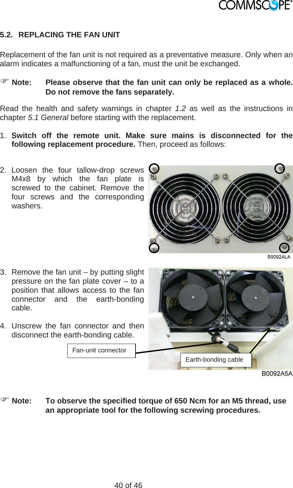
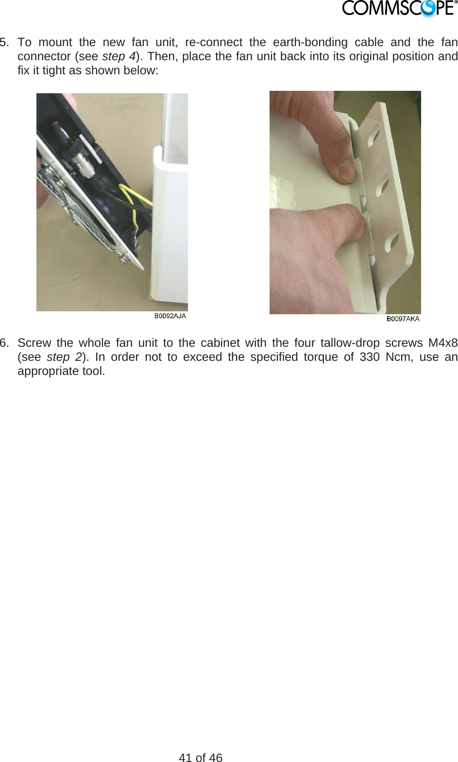
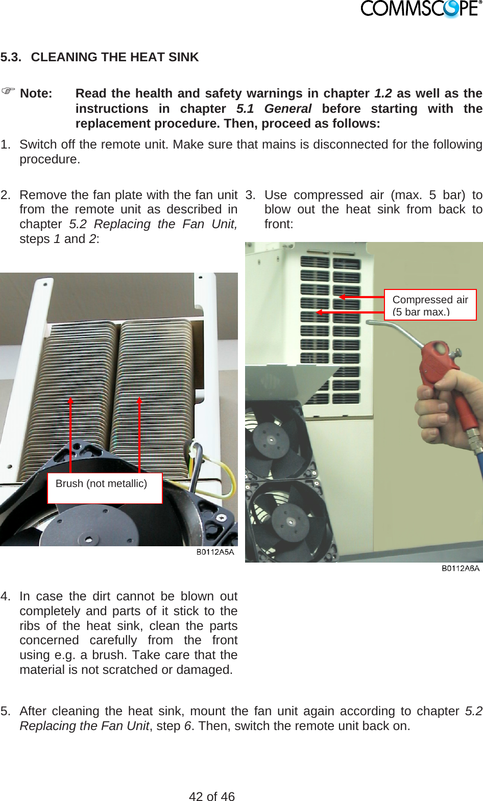
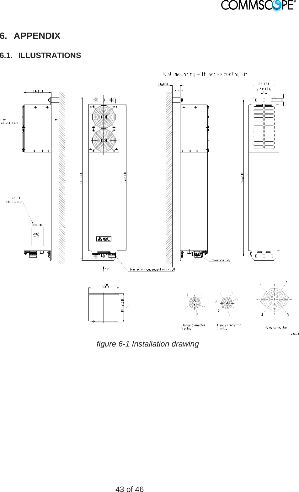
user manual
user manual
Navigation menu
Upload a User Manual
Namespaces
Wiki Guide
HTML
PDF
Info
Views
User Manual
Discussion / Help
Navigation
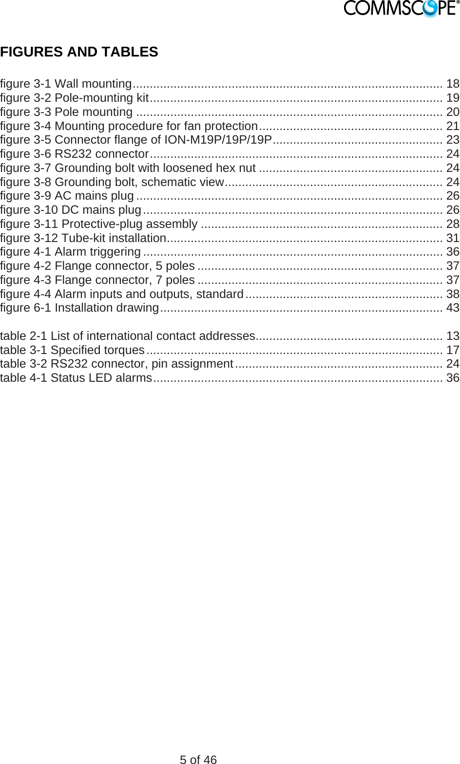
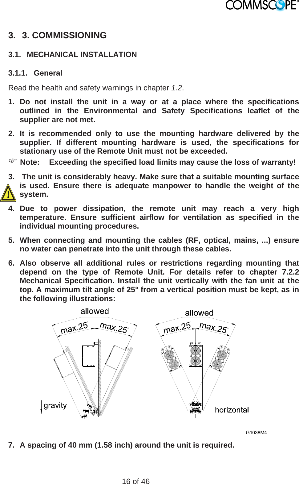
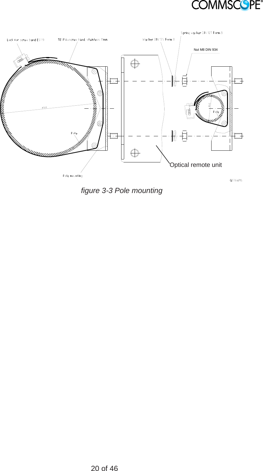
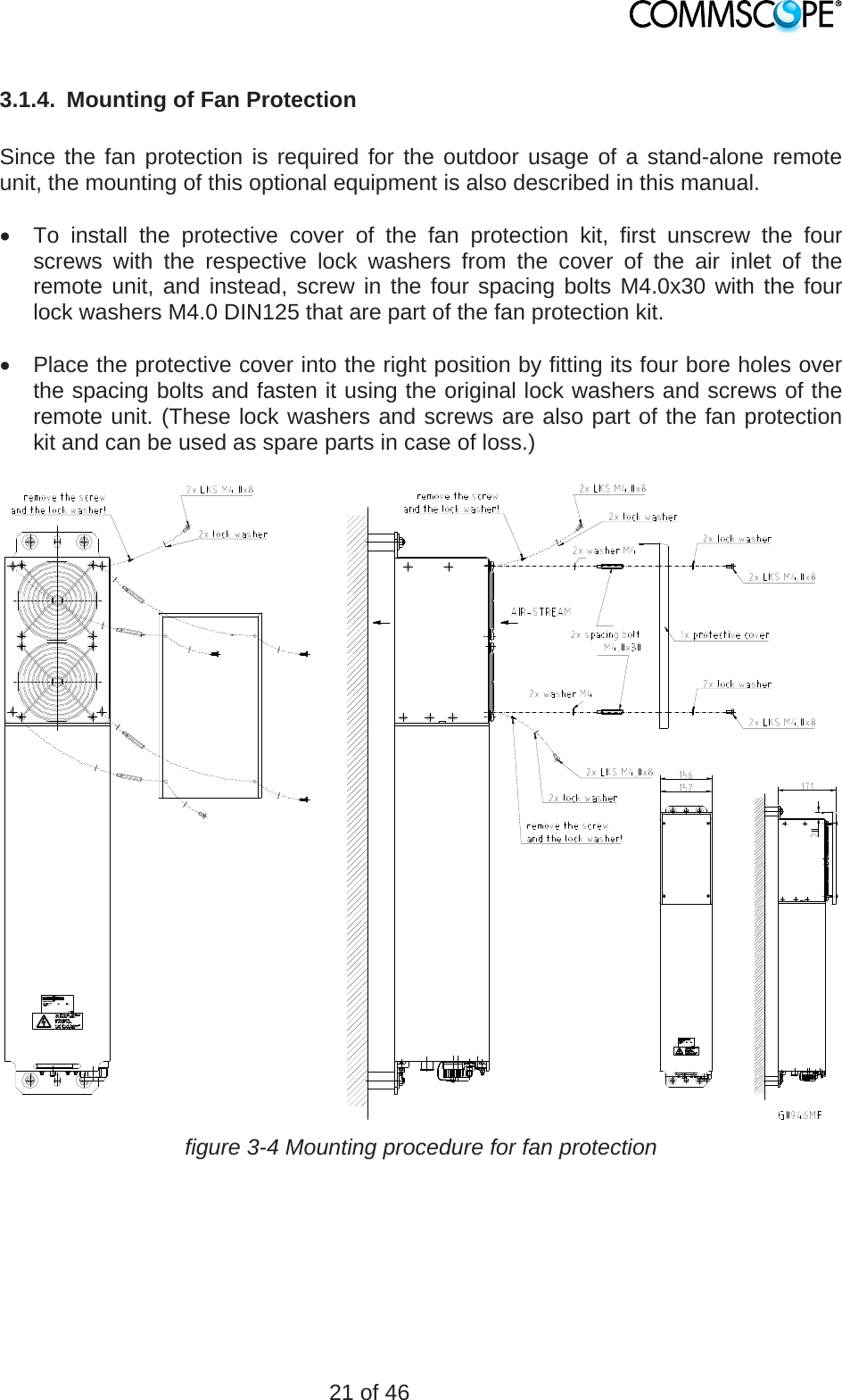
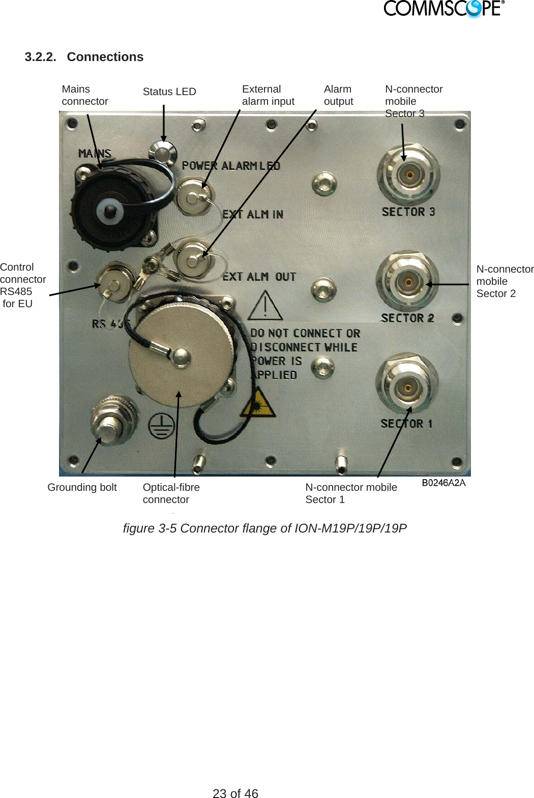
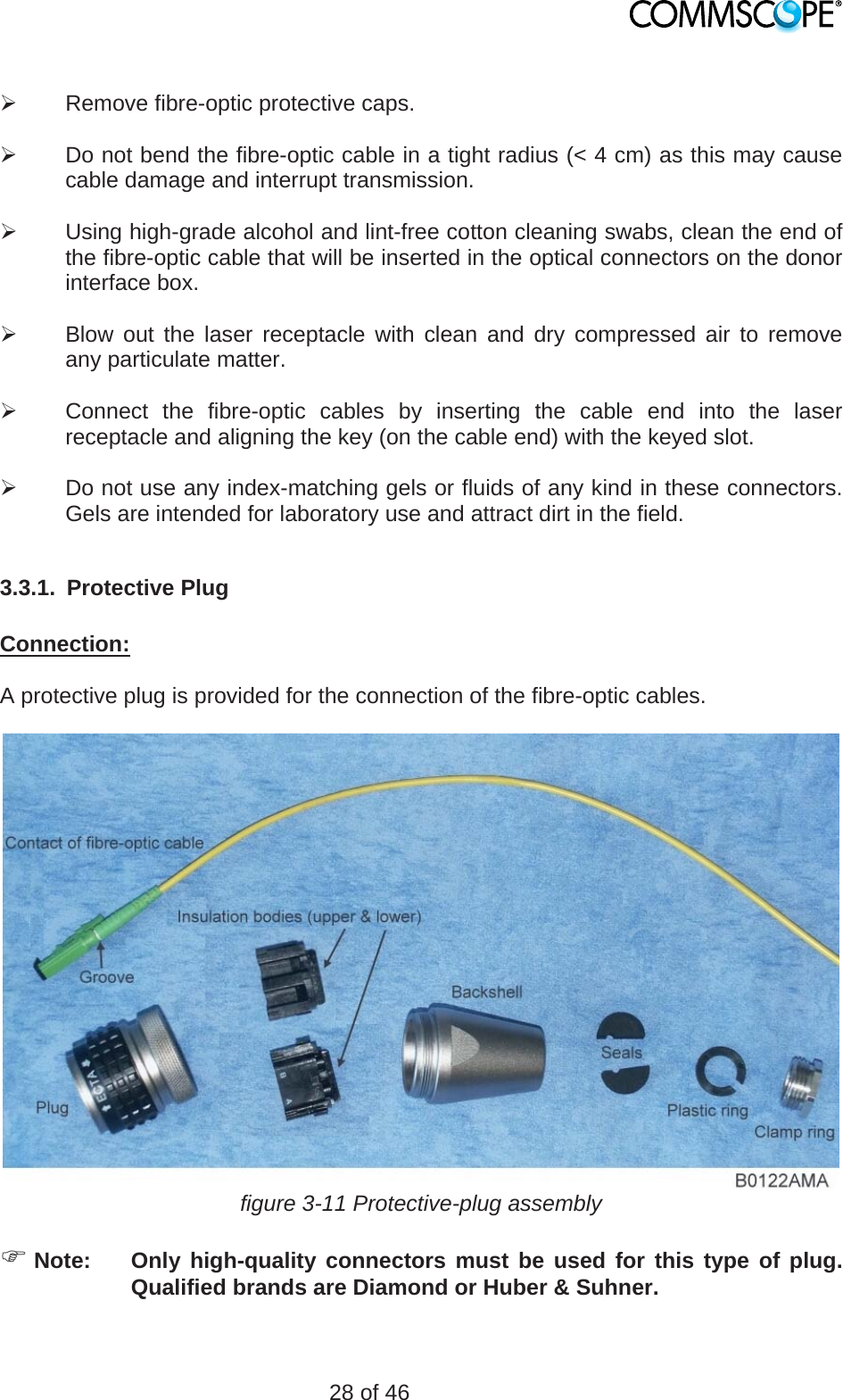
![7 of 46 1.2. HEALTH AND SAFETY WARNINGS 1. Only suitably qualified personnel are allowed to work on this unit and only after becoming familiar with all safety notices, installation, operation and maintenance procedures contained in this manual. 2. Read and obey all the warning labels attached to the unit. Make sure that the warning labels are kept in a legible condition and replace any missing or damaged labels. 3. Obey all general and regional installation and safety regulations relating to work on high voltage installations, as well as regulations covering correct use of tools and personal protective equipment. 4. Keep operating instructions within easy reach and make them available to all users. 5. It is the responsibility of the network provider to implement prevention measures to avoid health hazards which may be associated to radiation from the antenna(s) connected to the unit.\ 6. Laser radiation! Do not stare into the beam; do not view it directly or with optical instruments. 7. For installations which have to comply with FCC RF exposure requirements, the antenna selection and installation must be completed in a way to ensure compliance with those FCC requirements. Depending on the RF frequency, rated output power, antenna gain, and the loss between the repeater and antenna, the minimum distance D to be maintained between the antenna location and human beings is calculated according to this formula: ]/[][][24cmmWmWcm PDPD where P (mW) is the radiated power at the antenna, i.e. the max. rated repeater output power in addition to the antenna gain minus the loss between the repeater and the antenna. PD (mW/cm²) is the allowed Power Density limit acc. to 47 CFR 1.1310 (B) for general population / uncontrolled exposures which is o F (MHz) / 1500 for frequencies from 300MHz to 1500MHz o 1 for frequencies from 1500MHz to 100.000MHz RF exposure compliance may need to be addressed at the time of licensing, as required by the responsible FCC Bureau(s), including antenna co-location requirements of 1.1307(b)(3).](https://usermanual.wiki/Andrew-Wireless-System/M191919P.user-manual/User-Guide-1814358-Page-7.png)