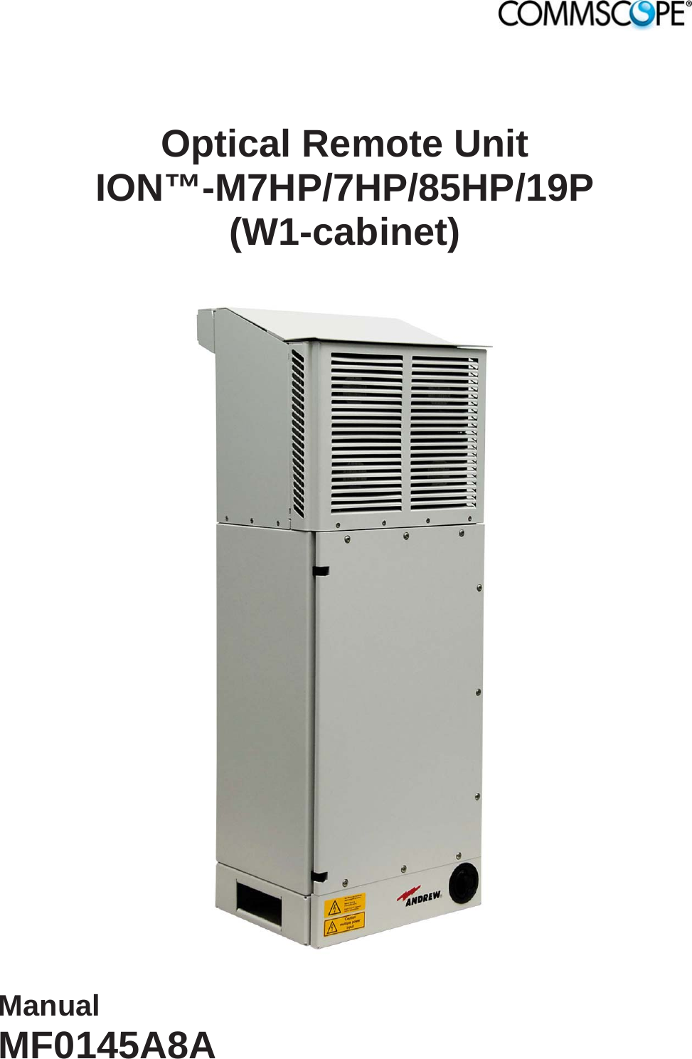
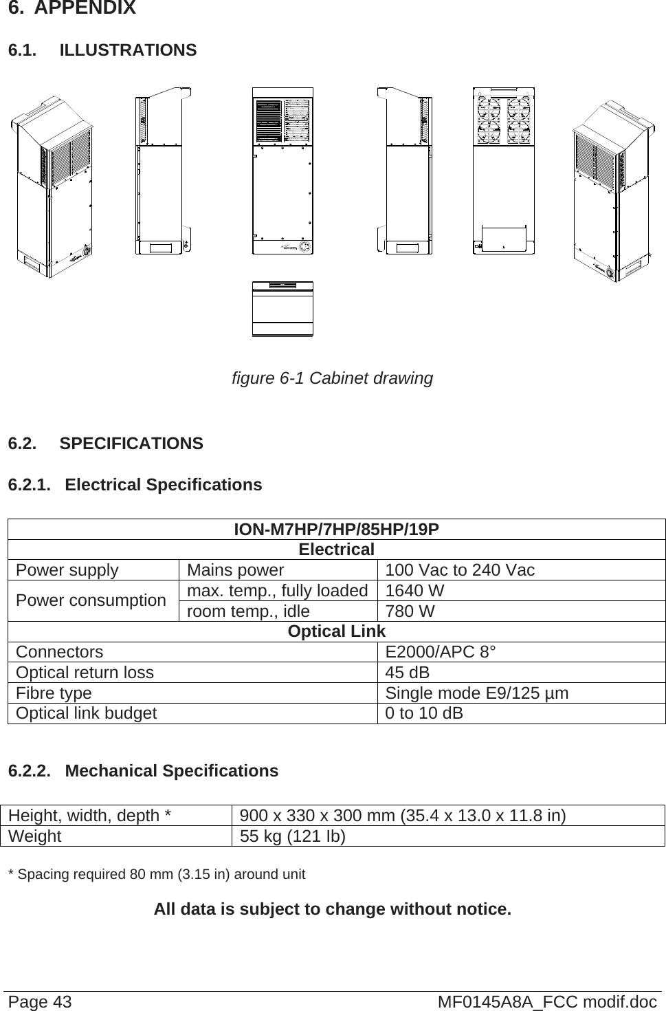
Andrew Wireless System M7785HP19P ION-M Remote Unit for cellular systems User Manual Additional information on SM2009

Andrew Wireless System ION-M Remote Unit for cellular systems Additional information on SM2009

Contents

user manual

  Optical Remote Unit ION™-M7HP/7HP/85HP/19P (W1-cabinet)    Manual MF0145A8A
 Manual for ION-M7HP/7HP/85HP/19P (W1-Cabinet) Page 2  MF0145A8A_FCC modif.doc                            © Copyright 2012 CommScope, Inc.  All rights reserved. CommScope Solutions is a trademark of CommScope, Inc.  All information contained in this manual has been revised thoroughly. Yet CommScope Solutions accepts no liability for any omissions or faults. CommScope Solutions reserves the right to change all hardware and software characteristics without notice. Names of products mentioned herein are used for identification purposes only and may be trademarks and / or registered trademarks of their respective companies. No parts of this publication may be reproduced, stored in a retrieval system, transmitted in any form or by any means, electronical, mechanical photocopying, recording or otherwise, without prior written permission of the publisher.  Andrew Wireless Systems GmbH, 03-May-2012
   Page 3 TABLE OF CONTENTS 1. GENERAL 5 1.1. USED ABBREVIATIONS 5 1.2. HEALTH AND SAFETY WARNINGS 6 1.3. ABOUT COMMSCOPE SOLUTIONS 8 1.4. INTERNATIONAL CONTACT ADDRESSES FOR CUSTOMER SUPPORT 9 2. INTRODUCTION 12 2.1. PURPOSE 12 2.2. THE ION-M7HP/7HP/85HP/19P (INTELLIGENT OPTICAL NETWORK; MMR) 12 2.3. VSWR ALARMING OPTION 13 3. COMMISSIONING 15 3.1. MECHANICAL INSTALLATION 15 3.1.1. General 15 3.1.2. Wall-Mounting Procedure 17 3.2. ELECTRICAL INSTALLATION 18 3.2.1. General 18 3.2.2. Connections 19 3.2.3. Grounding 20 3.2.4. Connection of the Antenna Cables 20 3.2.5. Connection of AC Mains Power 21 3.2.6. Connection of Optical-Fibre-Cable - Rules 22 3.2.7. Protective Plug 24 3.2.8. Protective-Tube Kit 26 3.2.9. Connection of External-Alarms Cable 28 3.3. COMMISSIONING 29 4. ALARMS 33 4.1. BITE AND ALARMS 33 4.2. HANDLING OF ALARMS 33 4.3. ALARM STATUS 33 4.4. STATUS LED ALARMS 33 4.5. APPLICATION BOARD 35 4.5.1. External-Alarm Inputs and Outputs 35 4.5.2. Layout and Connector Description 36 4.6. TROUBLESHOOTING 38 5. MAINTENANCE 39 5.1. GENERAL 39 5.2. REPLACING THE FAN UNIT 40
Manual for ION-M7HP/7HP/85HP/19P (W1-cab) Page 4  MF0145A8A_FCC modif.doc 5.3. CLEANING THE HEAT SINK 42 6. APPENDIX 43 6.1. ILLUSTRATIONS 43 6.2. SPECIFICATIONS 43 6.2.1. Electrical Specifications 43 6.2.2. Mechanical Specifications 43 6.2.3. Environmental and Safety Specifications 44 6.3. SPARE PARTS 44 7. INDEX 45  FIGURES AND TABLES  figure 3-1 Wall mounting........................................................................................... 17 figure 3-2 Connector flange of ION-M7HP/7HP/85HP/19P....................................... 19 figure 3-3 Caution labels........................................................................................... 19 figure 3-4 Grounding bolt with loosened hex nut, exemplary.................................... 20 figure 3-5 Grounding bolt, schematic view................................................................ 20 figure 3-6 Position of AC mains connectors at connector flange .............................. 21 figure 3-7 AC mains plug, front view......................................................................... 21 figure 3-8 Protective-plug assembly ......................................................................... 24 figure 3-9 Tube-kit installation................................................................................... 27 figure 4-1 External-alarm inputs and outputs, location.............................................. 36 figure 4-2 Application board, connectors .................................................................. 36 figure 4-3 External-alarm outputs, relay contacts in alarm condition ........................ 37 figure 4-4 28 V DC connector, location on distribution board ................................... 38 figure 6-1 Cabinet drawing........................................................................................ 43  table 1-1 List of international contact addresses....................................................... 11 table 3-1 Specified torques....................................................................................... 16 table 4-1 Status LED alarms..................................................................................... 34
 Page 5  MF0145A8A_FCC modif.doc 1.  GENERAL 1.1.  USED ABBREVIATIONS  3GPP   3rd Generation Partnership Project AC/DC    Alternating current / Direct Current AIMOS   Andrew Integrated Management and Operating System ALC    Automatic Level Control BITE   Built-In Test Equipment BTS    Base Transceiver Station CE    "Conformité Européenne" ("European Conformity") CD   Compact Disk CPD    Channel Power Detection DL   Downlink DoC    Declaration of Conformity EDGE    Enhanced Data Rates for GSM Evolution EN   European Norm EP   Extension Port ESD   Electrostatic Discharge ETS    European Telecommunication Standard EU   Extension Unit GSM    Global System for Mobile Communication GND   Ground GUI    Graphical User Interface ICP3    Intercept Point 3rd order ID No    Identification Number ION    Intelligent Optical Network IP   Ingress Protection ISO    International Organization for Standardization LED    Light Emitting Diode LMT    Local Maintenance Terminal LTE    Long Term Evolution MIMO    Multiple Input Multiple Output MS   Mobile Station MU   Main Unit NF   Noise Figure OTRx    Optical Transceiver = SRMU (Subrack Master Unit) PDU    Power Distribution Unit PG   Packing Gland PIM   Passive Intermodulation Pin   Input power Pout    Output power R&TTE   Radio & Telecommunications Terminal Equipment Rev   Revision RF   Radio Frequency RU   Remote Unit RX   Receiver SNMP    Simple Network Management Protocol TS   Technical Specification TX   Transmitter UL   Uplink UMTS    Universal Mobile Telecommunication System UPS    Uninterruptible Power Supply VSWR    Voltage Standing Wave Ratio WCDMA  Wideband Code Division Multiple Access WDM   Wavelength Division Multiplex
 1.2.  HEALTH AND SAFETY WARNINGS  1.  Only suitably qualified personnel is allowed to work on this unit and only after becoming familiar with all safety notices, installation, operation and maintenance procedures contained in this manual. 2.  Read and obey all the warning labels attached to the unit. Make sure that the warning labels are kept in a legible condition and replace any missing or damaged labels. 3.  Obey all general and regional installation and safety regulations relating to work on high voltage installations, as well as regulations covering correct use of tools and personal protective equipment. 4.  Keep operating instructions within easy reach and make them available to all users. 5.  It is the responsibility of the network provider to implement prevention measures to avoid health hazards which may be associated to radiation from the antenna(s) connected to the unit. 6.  Note for a Class A digital device or peripheral: This equipment has been tested and found to comply with the limits for a Class A digital device, pursuant to part 15 of the FCC Rules. These limits are designed to provide reasonable protection against harmful interference when the equipment is operated in a commercial environment. This equipment generates, uses, and can radiate radio frequency energy and, if not installed and used in accordance with the instruction manual, may cause harmful interference to radio communications. Operation of this equipment in a residential area is likely to cause harmful interference in which case the user will be required to correct the interference at his own expense. 7.  Make sure, access is restricted to qualified personnel. 8.  Only licence holders for the respective frequency range are allowed to operate this unit. 9.  Corresponding local particularities and regulations must be observed. For national deviations please refer to the respective documents included in the manual CD delivered. 10. Use this equipment only for the purpose specified by the manufacturer. Do not carry out any modifications or fit any spare parts which are not sold or recommended by the manufacturer. This could cause fires, electric shock or other injuries. 11. Due to power dissipation, the repeater may reach a very high temperature. Do not operate this equipment on or close to flammable materials. Page 6  MF0145A8A_FCC modif.doc
 12. Before opening the unit, disconnect mains. 13. ESD precautions must be observed! Before commencing maintenance work, use the available grounding system to connect ESD protection measures. 14. This unit complies with European standard EN60950. 15. Make sure the repeater settings are according to the intended use (see also product information of manufacturer) and regulatory requirements are met. 16. Although the repeater is internally protected against overvoltage, it is strongly recommended to earth the antenna cables close to the repeater’s antenna connectors for protection against atmospheric discharge. 17. Laser radiation! Do not stare into the beam; do not view it directly or with optical instruments.  Page 7  MF0145A8A_FCC modif.doc
 Page 8  MF0145A8A_FCC modif.doc 1.3.  ABOUT COMMSCOPE SOLUTIONS  CommScope Solutions is the foremost supplier of one-stop, end-to-end radio frequency (RF) solutions. Our products are complete solutions for wireless infrastructure from top-of-the-tower base station antennas to cable systems and cabinets, RF site solutions, signal distribution, and network optimization.  CommScope Solutions has global engineering and manufacturing facilities. In addition, it maintains field engineering offices throughout the world.  Andrew Wireless Systems GmbH based in Buchdorf/ Germany, which is part of CommScope Solutions, is a leading manufacturer of coverage equipment for mobile radio networks, specializing in high performance, RF and optical repeaters. Our optical distributed networks and RF repeater systems provide coverage and capacity solution for wireless networks in both indoor installations and outdoor environments, e.g. tunnels, subways, in-trains, airport buildings, stadiums, skyscrapers, shopping malls, hotels and conference rooms.   Andrew Wireless Systems GmbH operates a quality management system in compliance with the requirements of ISO 9001 and TL 9000. All equipment is manufactured using highly reliable material. To maintain highest quality of the products, comprehensive quality monitoring is conducted at all fabrication stages. Finished products leave the factory only after a thorough final acceptance test, accompanied by a test certificate guaranteeing optimal operation.   Note:  Exceptions of and national deviations from this intended use may be possible. To observe corresponding local particularities and regulations, please refer to the respective documents (also in national language) which are included in the manual CD delivered.  To make the most of this product, we recommend you carefully read the instructions in this manual and commission the system only according to these instructions.   For technical assistance and support, please also contact the local office or CommScope Solutions directly at one of the addresses listed in the following chapter.
 Page 9  MF0145A8A_FCC modif.doc 1.4.  INTERNATIONAL CONTACT ADDRESSES FOR CUSTOMER SUPPORT  Americas:  Canada United States CommScope Solutions Canada  Andrew LLC, A CommScope Company Mail  505 Consumers Road, Suite 803  Toronto M2J 4V8  Canada  Mail  620 North Greenfield Parkway Garner, NC 27529 U.S.A. Phone  +1-905-878-3457 (Office) +1-416-721-5058 (Cell) Phone +1-888-297-6433 Fax +1-905-878-3297  Fax  +1-919-329-8950 E-mail  Peter.Masih@commScope.com, wisupport.us@commScope.com  E-mail wisupport.us@commScope.com  Caribbean & South American Region (CALA)  Caribbean (CALA) & Central American Region  CommScope Cabos do Brasil Ltda.  CommScope Mexico S.A. de C.V. Mail CALA Tech Support for Distributed Coverage & Capacity Solutions (DCCS) products:  Rua Guaporanga, 49 Praça Seca – Rio de Janeiro – RJ ZIP: 21320-180 Brazil Mail CALA Tech Support for Distributed Coverage & Capacity Solutions (DCCS) products:  Av. Insurgentes Sur 688, Piso 6 Col. Del Valle, CP: 03100 Mexico City Mexico Phone  +1-815-546-7154 (Cell) +55-15-9104-7722 (Office)  Phone  +52-1-55-5419-5260 (Cell) +52-55-1346-1900 (Office) Fax + 55-15-2102-4001  Fax +52-55-1346-1901  E-mail wisupport@commScope.com  E-mail wisupport@commScope.com  APAC Countries:  China, India and Rest of Asia  Australia & New Zealand Andrew International Corporation  Andrew Corporation (Australia) Pty Ltd. Mail Room 915, 9/F  Chevalier Commercial Centre 8 Wang Hoi Rd Kowloon Bay  Hong Kong Mail Unit 1 153 Barry Road Campbellfield  VIC  3061 Australia Phone +852-3106-6100  Phone +613-9300-7969 Fax +852-2751-7800  Fax +613-9357-9110 E-mail wisupport.China@commScope.com  E-mail wisupport.Australia@commScope.com
 Page 10  MF0145A8A_FCC modif.doc  Europe:  United Kingdom  Scandinavia Andrew Wireless Systems UK Ltd  Andrew Norway (AMNW) Mail Unit 15, Ilex Building Mulberry Business Park Fishponds Road  Wokingham Berkshire RG41 2GY England Mail P.O. Box 3066  Osloveien 10  Hoenefoss 3501  Norway Phone  +44-1189-366-792  Phone  + 47 32-12-3530 Fax  +44-1189-366-773  Fax  + 47 32-12-3531 E-mail wisupport.uk@commScope.com E-mail wisupport@commScope.com  Germany France Andrew Wireless Systems GmbH  CommScope France Mail  Industriering 10 86675 Buchdorf Germany  Mail Immeuble Le Lavoisier 4, Place des Vosges 92052 Courbevoie France Phone  +49-9099-69-0  Phone  +33-1 82 97 04 00 Fax  +49-9099-69-930  Fax  +33-1 47 89 45 25 E-mail wisupport@commScope.com  E-mail wisupport@commScope.com  Austria Switzerland Andrew Wireless Systems (Austria) GmbH  Andrew Wireless Systems AG Mail  Weglgasse 10 2320 Wien-Schwechat Austria  Mail  Tiergartenweg 1 CH-4710 Balsthal Switzerland Phone +43-1706-39-99-10  Phone  +41-62-386-1260 Fax +43-1706-39-99-9  Fax  +41-62-386-1261 E-mail wisupport.austria@commScope.com  E-mail wisupport.ch@commScope.com  Italy  Iberia Region - Spain & Portugal CommScope Italy S.r.l., Faenza, Italy  Andrew España S.A. A CommScope Company Mail  Via Mengolina, 20 48018 Faenza (RA) Italy  Mail Avda. de Europa, 4 - 2ª pta. Parque Empresarial de la Moraleja Alcobendas, Madrid 28108 Spain Phone +39-0546-697111  Phone +34-91-745-20 40 Fax +39-0546-682768  Fax +34-91-661-87 02 E-mail wisupport.italia@commScope.com  E-mail wisupport.iberia@commScope.com
 Page 11  MF0145A8A_FCC modif.doc  Czech Republic   CommScope Solutions Czech Republic C-Com, spol. s r.o   Mail  U Moruší 888 53006 Pardubice Czech Republic    Phone  +49 871 9659171 (Office) +49 171 4001166 (Mobile)   Fax  +49 871 9659172     E-mail wisupport@commScope.com     Africa & Middle East:  Middle East & North Africa  South Africa CommScope Solutions International Inc. (Branch)  Andrew Wireless Solutions Africa (PTY) LTD Mail PO Box 48 78 22 Unit 3206, Floor 32, Jumeirah Business Center 5,  Jumeirah Lakes Towers, Dubai United Arab Emirates Mail 11 Commerce Crescent West Eastgate, Sandton  PO Box 786117 Sandton 2146 South Africa Phone  +971 4 390 09 80  Phone  + 27 11-719-6000 Fax  +971 4 390 86 23  Fax  + 27 11-444-5393  E-mail wisupport@commScope.com  E-mail wisupport@commScope.com  table 1-1 List of international contact addresses
 Page 12  MF0145A8A_FCC modif.doc 2.  INTRODUCTION 2.1.  PURPOSE  Cellular telephone systems transmit signals in two directions between a base transceiver station (BTS) and mobile stations (MS) within the signal coverage area.  If weak signal transmissions occur within the coverage area because of indoor applications, topological conditions or distance from the transmitter, extension of the transmission range can be achieved by means of an optical distribution system.  Such a system contains an optical Master Unit and several Remote Units. The number of the Remote Units depends on the hardware and software configuration. The Remote Units are connected to the Master Unit with optical links. The optical loss must be less than 10 dB inclusive optical couplers or splitters.  The Master Unit is the connection to the base transceiver stations. The configuration of a Master Unit depends on the number of the Remote Units and the frequency range.   WDM (Wave Division Multiplex) filters are integrated in the optical modules. For the UL, a wavelength within 1540 nm - 1562 nm is used. For the DL, a wavelength of 1310 ±20 nm is used. The maximum output power for the UL and DL is 5.7 mW.  2.2.  THE ION-M7HP/7HP/85HP/19P (INTELLIGENT OPTICAL NETWORK; MMR)  The ION-M7HP/7HP/85HP/19P is an LTE MIMO, 850 MHz, and 1900 MHz CDMA/WCDMA multi-operator Remote Unit. It is used in conjunction with a Master Unit in the ION optical distribution system. This system transports LTE channels, and CDMA 850 MHz; and 1900 MHz signals simultaneously, providing a cost-effective solution for distributing capacity from one or more base stations.  The ION-M7HP/7HP/85HP/19P transports signals on the RF layer in a very inexpensive manner. This means that multiple operators and multiple technologies are moved simultaneously from a cluster of base stations to a remote location over the same fiber.  The ION optical distribution system is a cost-effective coverage solution for dense urban areas, tunnels, subway, airports, convention centers, high-rise buildings and other locations where physical structures increase path loss. It has been specifically designed to reduce zoning problems and to provide homogeneous coverage. The compact, mechanical design is specifically architected to mount along side structures in such a way that it has a minimal visual impact.
 Page 13  MF0145A8A_FCC modif.doc The ION is easily set-up and supervised via a graphical user interface (GUI). Remote units can be commissioned through the use of built-in test equipment. An auto-leveling function compensates for the optical link loss making installation easy and quick. The entire system may be monitored remotely via an Andrew OMC. This platform uses SNMP protocol and is compliant to X.733 standard.  Should a sophisticated interface not be required, the master unit can be directly connected to the alarm interface of a base station via its contact relay.   Features:    Multi-channel, multi-operator support   Reduced visual impact form factor   Efficient, high power amplifiers   Single fiber for MIMO and multiple remotes   Comprehensive operations and management system for configuration and alarming   OMC with SNMP according to X.733 standard  3GPP TS25.143/TS25.106/ TS36.143/TS36.106 and 3GPP2C.S0051-0 compliant   Easy installation and commissioning  2.3.  VSWR ALARMING OPTION  The VSWR Alarming Option is a remote-controlled data acquisition system for monitoring the VSWR of the 700 MHz LTE antenna interfaces. The differential power detector compares the power levels corresponding with the forward and reverse waves at the antenna interfaces. A VSWR alarm is always initiated in case of return loss lower than 2 dB. Return loss higher than 10 dB corresponds always with normal operation without defect. The return loss range between 2 and 10 dB is the ambiguity range, depending on the specific phase conditions at the antenna interfaces.
 Page 14  MF0145A8A_FCC modif.doc For your notes:
 3.  COMMISSIONING 3.1.  MECHANICAL INSTALLATION 3.1.1.  General  Read the health and safety warnings in chapter 1.2 Health and Safety Warnings .  1. Do not install the unit in a way or at a place where the specifications outlined in the Environmental and Safety Specifications leaflet of the supplier are not met.  2. It is recommended only to use the mounting hardware delivered by the supplier. If different mounting hardware is used, the specifications for stationary use of the Remote Unit must not be exceeded.   Note:  Exceeding the specified load limits may cause the loss of warranty!  3.   The unit is considerably heavy. Make sure that a suitable mounting surface is used. Ensure there is adequate manpower to handle the weight of the system.  4. Due to power dissipation, the Remote Unit may reach a very high temperature. Ensure sufficient airflow for ventilation as specified in the individual mounting procedures.  5.  When connecting and mounting the cables (RF, optical, mains, ...) ensure no water can penetrate into the unit through these cables.  6. Also observe all additional rules or restrictions regarding mounting that depend on the type of Remote Unit. For details refer to chapter 7.2.2 Mechanical Specification. Install the unit vertically with the fan unit at the top. A maximum tilt angle of 25° from a vertical position must be kept, as in the following illustrations:   Page 15  MF0145A8A_FCC modif.doc
 Page 16  MF0145A8A_FCC modif.doc  7.  A spacing of 40 mm (1.58 inch) around the unit is required.  8.  To ensure sufficient airflow when mounting the unit in enclosed spaces, two lid openings (one for the air inlet and the other for the air outlet) have to be provided. Do not block these air inlets and outlets when mounting the Remote Unit. The size of each opening must equal at least 17 x 17 cm (290 cm2). Make sure, too, there is no thermal short circuit between the air inlet and air outlet.   If any different or additional mounting material is used, ensure that the mounting remains as safe as the mounting designed by the manufacturer. Ensure that the static and dynamic strengths are adequate for the environmental conditions of the site. The mounting itself must not vibrate, swing or move in any way that might cause damage to the Remote Unit.  Specified torques have to be observed for certain mounting procedures according to the following table:  Type  Tallow-drop screws  Hex nuts  Spacing bolts  PG (plastic)  PG (aluminium)Thread M 4  M 8  M 4  M 8  PG 13.5  PG 29 Specified torques 3.3 Nm  27 Nm 2.3 Nm  27 Nm 3.75 Nm  10 Nm table 3-1 Specified torques   Note:  To avoid damage when mounting the unit, always make sure that the M8 washers (DIN9021 or DIN125 depending on the mounting kit) are placed behind and in front of the mounting drillings of the unit.  The mounting procedures for a stand-alone Remote Unit without optional accessories are described and illustrated in the following sections. For further information regarding special mounting procedures including mounting of accessory equipment, please see separate manual.
 3.1.2.  Wall-Mounting Procedure    Check the suitability of the wall-mounting kit and the wall.   Remove the protective cover from the top of the Remote Unit by pulling it strongly to the front.  Page 17  MF0145A8A_FCC modif.doc    Mark the position of the drilling holes (for exact measurements refer to the wall mounting plan that is part of the delivery). Drill three holes at the marked positions and insert dowels*.   Choose the screw type you want to use: two possible sets are provided in the kit; for details see mounting plan.  Screw two screws with the according washers / nuts into the two upper dowels but do not fasten them.   Hang the Remote Unit with the two upper holes into the upper screws and, then, fasten them tight using an appropriate tool.    figure 3-1 Wall mounting * The dowels are not part of the delivery since the suitable type depends on the on-site conditions (material of wall). Therefore, use dowels that are appropriate for the mounting surface.   Then, put the third screw with the according washers / nuts through the bottom hole of the Remote Unit and screw it into the third dowel using an appropriate tool.   Put the protective cover back on top of the Remote Unit.   Ensure that there is free access to the electrical connections as well as to the cabinet. The approved bending radius of the connected cables must not be exceeded. Bottom hole Upper holes Protective cover Pull strongly!
 3.2.  ELECTRICAL INSTALLATION 3.2.1.  General  Read the health and safety warnings in chapter 1.2. 1. This unit contains dangerous voltages. Loss of life, severe personal injury or property damage can be the result if the instructions contained in this manual are not followed. 2.  It is compulsory to ground the unit before connecting power supply. A grounding bolt is provided on the cabinet to connect the ground-bonding cable. 3.  Although the Remote Unit is internally protected against overvoltage, it is strongly recommended to earth the antenna cables close to the antenna connectors of the Remote Unit for protection against atmospheric discharge. In areas with strong lightning it is strongly recommended to insert additional lightning protection. 4.  If the mains connector of the Remote Unit is not easily accessible, a disconnect device in the mains circuit must be provided within easy reach. 5. Before connecting or disconnecting the mains connector at the Remote Unit, ensure that mains supply is disconnected. 6.  Make sure that an appropriate branch circuit breaker and an overcurrent limiting device are connected between mains and Remote Unit. 7.  An external circuit breaker is mandatory as disconnect device. This circuit breaker should be readily available for the operator.   For the U.S. and Canada, installation has to be done in accordance with the NEC (National Electronic Code). The external circuit breaker has to be a branch circuit breaker rated 20 A for 110 Vac mains.  8. A field wiring box with conduit must be used for the installation. Use a wire harness rated for AC mains with at least AWG14 size. 9.  A connection of mains supply to a power socket requires the power socket to be nearby the Remote Unit. 10. Incorrectly  wired  connections can destroy electrical and electronic components. 11. To avoid corrosion at the connectors caused by electrochemical processes, the material of the cable connectors must not cause a higher potential difference than 0.6 V (see electrochemical contact series). 12. Use an appropriate torque wrench for the coupling torque (25 N-m / 19 ft lb) of 7/16-DIN connectors with 1 ¼-inch opening to tighten the 7/16-type antenna connectors. For example, use torque wrench of item no. 244377 available from the Andrew e-catalog. Do NOT use your hands or any other tool (e.g. a pair of pliers)! This might cause damage to the connector and lead to a malfunction of the Remote Unit. 13. For unstabilized electric networks which frequently generate spikes, it is advised to use a voltage limiting device.  Page 18  MF0145A8A_FCC modif.doc
 14. The unit complies with the surge requirement according to EN 61000-4-5 (fine protection); however, it is recommended to install an additional medium (via local supply connection) and/or coarse protection (external surge protection) depending on the individual application in order to avoid damage caused by overcurrent. 15. Observe the labels on the front panels before connecting or disconnecting any cables!   3.2.2.  Connections Page 19  MF0145A8A_FCC modif.doc    figure 3-2 Connector flange of ION-M7HP/7HP/85HP/19P  Please observe the following two caution labels attached to the unit cabinet:      figure 3-3 Caution labels Cable glands for connection of external alarms inputs/ outputs Optical-fibre connector Status LED 7/16-connector Mobile 1 700 MHz Grounding bolt Mains  connectors 7/16-connector Mobile 2 1900 MHz
 3.2.3.  Grounding  Grounding must be carried out. Connect an earth-bonding cable to the grounding connection provided at the outside of the Remote Unit (see chapter 3.2.2 Connections). Do not use the grounding connection to connect external devices.      figure 3-4 Grounding bolt with loosened hex nut, exemplary  figure 3-5 Grounding bolt, schematic view  After loosening the hex nut, connect the earth-bonding cable between the two washers as illustrated in the figures above. Then, fasten all parts again with the hex nut.  3.2.4.  Connection of the Antenna Cables  The Remote Unit has 7/16-type antenna connectors. For its location please refer to chapter 3.2.2 Connections. For mounting the cable connectors, it is recommended to refer to the corresponding documentation of the connector manufacturer. The bending radius of the antenna cables must remain within the given specifications.  For the selection of cable and antenna it should be considered that, on the one hand, a cable with higher loss is less expensive but, on the other hand, it impairs performance.   It is sufficient to tighten the 7/16-type antenna connectors hand-tight. The use of a tool (like pliers) may cause damage to the connector and, therefore, lead to a malfunctioning of the Remote Unit.   Page 20  MF0145A8A_FCC modif.doc
 3.2.5.  Connection of AC Mains Power   Before connecting electrical power to the units, the system must be grounded as described in the previous chapter.  Mains power must be connected at the mains connectors of the unit (see chapter 3.2.2 Connections).  The power supply plug is part of the delivery. The correct wiring of the power supply plug is as follows:  2 AC mains cable connector   Cover of mains connectors fastened => Remove cover(s) to access PINs!  figure 3-6 Position of AC mains connectors at connector flange  Mains 1 + 2 Power Connectors- AC PIN Assignment:    Cover of  mains connectors removed figure 3-7 AC mains plug, front view Page 21  MF0145A8A_FCC modif.doc
  Parameter  Value Label / Name  MAINS 1 MAINS 2 Connector type  CONINVERS M 17 series P20 4(3+PE) PINs male PIN 1 2 3 4  L – Line conductor / Phase 1 (brown cable) N – Neutral conductor (blue cable) not connected (n.c.) PE – Protection Earth (green / yellow cable)    For the AC power supply connection, a minimum cross section of 1.5 mm2 is required. Each wire must observe the applicable national regulations regarding loop impedance, voltage drop, and methods of installation. Make sure to connect the correct voltage to the unit.   Note:  Do not connect or disconnect the power cord at the mains connector while power is on. Turn off mains power* before connecting the power cord at the remote unit, then, engage mains again. *   Mains power must be interruptible with an external mains breaker. For the mains breaker, observe the following recommendation:  120 Volt / 20 Amp max. or 240 Volt / 16 Amp, single-phase, 50 / 60 Hz AC service is needed, i.e. the external AC breaker should be 20 Amps max. for 120-Volt service or 16 Amps for 240-Volt service.  3.2.6.  Connection of Optical-Fibre-Cable - Rules  Optical signals are transmitted by use of optical fibres. When connecting these fibres observe the following instructions.    Note:  Care should be taken when connecting and disconnecting fibre-optic cables. Scratches and dust significantly affect system performance and may permanently damage the connector. Always use protective caps on fibre-optic connectors not in use.  In general, optical fibres do not need special protective measures. However, protection against environmental influences e.g. rodents and humidity must be considered.  The optical fibre is a single mode fibre. Type is E9/125 µm with the following minimum requirements: Page 22  MF0145A8A_FCC modif.doc
  Attenuation:   <0.36 dB / km @ 1310 nm  /  <0.26 dB / km @ 1550 nm Dispersion:  <3.5 ps / nm km @ 1310 nm  /  <18.0 ps / nm km @ 1550 nm  The specified bending radius of the optical fibres must not be exceeded. The pigtails for the connection between Master Unit and Remote Unit must have a sufficient length. A protection for the feeding into units must be given. The system attenuation of the optical fibres, including the connectors, must not exceed 10 dB.  System attenuation and attenuation of optical components must be determined. This can be achieved by measuring attenuation and reflection with an appropriate measuring instrument. For pigtails, a total value of < 0.4 dB (measured to a reference plug) can be assumed due to the dead zone of the reflectometer. These measurements must be made with a sufficient length of optical fibre, at the input and output of the device which has to be measured.  Fibre-cable connectors have to be of the same type (E2000APC8°) as the connectors used for the unit. The fibre-optic cables are connected to the optical transceiver.    Angled connectors are not compatible with straight optical connectors; non-compatibility of connectors will result in permanent damage to both connectors.  Before connecting the fibre cables, follow the procedure below to ensure optimized performance. It is important for these procedures to be carried out with care:    Remove fibre-optic protective caps.    Do not bend the fibre-optic cable in a tight radius (< 4 cm) as this may cause cable damage and interrupt transmission.    Using high-grade alcohol and lint-free cotton cleaning swabs, clean the end of the fibre-optic cable that will be inserted in the optical connectors on the donor interface box.    Blow out the laser receptacle with clean and dry compressed air to remove any particulate matter.    Connect the fibre-optic cables by inserting the cable end into the laser receptacle and aligning the key (on the cable end) with the keyed slot.    Do not use any index-matching gels or fluids of any kind in these connectors. Gels are intended for laboratory use and attract dirt in the field.  Page 23  MF0145A8A_FCC modif.doc
 3.2.7.  Protective Plug  Connection:  A protective plug is provided for the connection of the fibre-optic cables.   figure 3-8 Protective-plug assembly   Note:  Only high-quality connectors must be used for this type of plug. Qualified brands are Diamond or Huber & Suhner.  Page 24  MF0145A8A_FCC modif.doc
 For plug assembly, observe the following instruction:  1.  Pass one or two contacts through the backshell and the clamp ring. 2.  Place the contact(s) on the lower insulation body by pushing the groove of the contact into the cavity. If there is only one contact, cavity A must be used. * 3.  Then, mount the upper insulation body on the lower insulation body. **  4.  Bring the insulator into the plug. The narrow groove of the insulator must be fitted into the stamp of the plug.    Page 25  MF0145A8A_FCC modif.doc *  To release the contact for disassembling, push the inner snap to the side and pull the contact out. **  To release upper and lower insulation bodies for disassembling, use a small screwdriver and carefully open the snap-connections at the left and the right side of the insulator without damaging them.  5.  Fasten the insulator by screwing the backshell tight onto it. Use a spanner with opening 32 to screw the backshell tight (no gap). 6.  Place the appropriate seal parts (with one groove for one contact or two grooves for two contacts) over the cable(s) and push them into the backshell. Seals with one groove No gap Cavity B Upper insulation body Cavity A
  7.  Bring the plastic ring over the cable(s), push it into the backshell and compress the seals and plastic ring by screwing the clamp ring tight (no gap) using a spanner with opening 20. ***   8. Connect the plug to the optical-fibre connector of the remote unit, again by fitting a stamp on the plug into the groove of the connector.  9.  To lock the connector, push the black locking ring forward.****  Screw tight until gap is closed Page 26  MF0145A8A_FCC modif.doc ***  For disassembling, release the clamping ring and remove the seals and the plastic ring first. ****  Locking mechanism: The system of locking the plug is based on a “push-pull” mechanism. The locking ring has to be pushed forward to lock the connector and pulled back to free the connection.  3.2.8.  Protective-Tube Kit  As additional protection for the optical fibers, this connector type can be supplemented by a special tube kit. To fasten the tube correctly, first unscrew the clamp ring (if already installed) of the original plug kit.   Then, proceed according to the following instruction:  Groove  Push forward to lock, pull back to free connection
   Page 27  MF0145A8A_FCC modif.doc  Screw the reducer to the protective plug backshell without any gap!Place the appropriate seal parts (with) one groove for one contact or two grooves for two contacts) over the cable(s) and push them into the backshell! Protective tubeReducerCouplingProtective plugFiber cableRing 3/4G1055M0   figure 3-9 Tube-kit installation   Push the fiber-optic cable carefully through the tube until it comes out at the other end.
 3.2.9.  Connection of External-Alarms Cable  To connect the external alarms cable inside the RU to the inputs and/ or outputs of the external alarm connector, proceed as follows: Page 28  MF0145A8A_FCC modif.doc  1. Loosen the sleeve nut provided for the external alarm inputs/ outputs connector from the cable gland on the connector flange with the help of an open-end wrench (of size 20 mm).   2. Remove the seal insert (black) and plastic rod cut (white) from the clamp seal (grey).       3. Outside the RU first fit the sleeve nut and second the clamp seal of the cable gland onto the external alarms cable.  4. Insert the external alarms cable together with the corresponding seal insert into the cable-gland feedthrough.  5. Fasten the sleeve nut on top of the cable gland again with the help of the open-end wrench (of size 20). Note: Ensure tightness of the screw! Sleeve nut removed Nut removed Rod cut  Clamp seal Seal insert 2 cable glands for connection of  Alarm output External  alarm input
  6. Connect the mains cable to the clamps (part of the delivery) provided at the external alarm input/ output connector block located at the application board in the interior of the RU.    For more detailed information on the external alarm inputs and outputs please refer to chapters 4.5.1 External-Alarm Inputs and Outputs and 4.5.2 Layout and Connector Description. Application board Page 29  MF0145A8A_FCC modif.doc  3.3.  COMMISSIONING  Read the health and safety warnings in chapter 1.2 as well as the description carefully to avoid mistakes and proceed step by step as described!    Do not operate the Remote Unit without terminating the antenna connectors. The antenna connectors may be terminated by connecting them to their respective antennas or to a dummy load.   Only qualified personnel should carry out the electrical, mechanical, commissioning and maintenance activities that require the unit to be powered on when open.   When opening the Remote Unit do not damage the warranty labels on the internal devices. The warranty is void if the seals are broken.   Ensure that all connections have been performed according to chapter 3.2.2 Connections.  Connecting clamps of external alarms
 Commissioning an ION-M Remote UnitStartMechanical installationFasten wall or pole mounting kit to wall or pole.Manual  for Remote UnitElectrical connectionsConnect grounding cable and ground the RU.MainsSwitch mains power on.Philips screwdriverScrew driverSpanner, size 13 mmElectrical connectionsConnect AC power to the power cable. Ensure there is a circuit breaker between mains and RU.RF connectionConnect antenna cable to antenna port.Optical connectionsMount the optical fibre with E2000 APC8° connector into the connector. Plug the connector into the RU.Mechanical installationMount RU to mounting kit, ensure suffient air flow and avoid thermal short circuits.PreperationUnpack RU, RU accessories and mounting kit.External devicesConnect external devices to the external in or alarm out connectors, or to the connecting board inside the RU.Mounting kitSpanner, size 13 mmDrilling machineDowelsScrew driverGrounding cableSpanner 13 mmMains cableConnecting kitAlarm kit (M-cabinet)E2000 APC8° connectorSpanner with opening 32  PIN 1 - L   PIN 2 - NPIN 3 - n.c.PIN 4 - PEPage 30  MF0145A8A_FCC modif.doc
 Output:All RUs okay.Go to MUExternal errorClose the door (RUs with a door).  Check externally connected devices.Check fibre loss of optical link.Check optical connectors.Clean optical connectors.Check optical output power of corresponding OTRx at master unit.ALC alarm: Decrease DL input power of affected band.VSWR alarm: Check antenna and cable.LED statusProceed to MU to set up the SWOrangeYesInternal ErrorChange power supply (RUs with a door).Reduce environmental temperature. Eliminate thermal short circuit.Disconnect and connect mains. Fans should run. If not, replace the fans at RU. MU: Change amplifier setting at MU controllerRedLED statusYellowGreenRedFinished setting up all RUs?GreenSpare RU available?YesContact customer serviceNoYesLED on?Check power switch inside RU (RUs with door).Check mains cabling.Check mains power.NoNo  Page 31  MF0145A8A_FCC modif.doc
 Page 32  MF0145A8A_FCC modif.doc For your notes:
 Page 33  MF0145A8A_FCC modif.doc 4.  ALARMS 4.1.  BITE AND ALARMS  The Built-In Test concept comprises the monitoring of the power supplies, the power amplifiers and the optical interface.  All occurring alarms can be checked via software at the Master Unit.  4.2.  HANDLING OF ALARMS  As soon as the software acknowledges a valid alarm, a message is transmitted to the Master Unit.  If the reason for the alarm has been cleared or if the alarm should continue, a new alarm message will not be repeated. If there was an interruption of at least five seconds after acknowledgement, a new alarm message will be generated.  4.3.  ALARM STATUS  For details refer to the corresponding software documentation of the Master Unit.  4.4.  STATUS LED ALARMS  For local supervision, a status LED on the connector flange of the remote unit gives an indication of possible reasons for alarms. This table shows possible on-site measures that could be checked before referring to the master unit alarm list.  Status LED Indication  Alarms  Possible on-site measures Green  No alarm  Status ok   Door alarm  Close the door (RUs with door). Alarms not directly related to RU:  External alarms  Check externally connected devices. Optical alarm Rx Check fibre loss of optical link. Check optical connectors. Clean optical connectors. (MU: Check optical output power of corresponding OTRx at master unit). Orange ALC alarm  (MU: Decrease DL input power of affected band). Alarms directly related to RU: Red Power 28 V  Change power supply (RUs with door). Replace the affected remote unit.
 Page 34  MF0145A8A_FCC modif.doc Temperature  Reduce environmental temperature.  Eliminate thermal short circuit. Fan  Disconnect and connect mains. Fans should run. If not, replace the fans at RU. I²C  Disconnect and connect mains. Optical alarm Tx  Exchange RU. Amplifier “Power Down”  (MU: Change amplifier setting at MU controller). Status LED off  Mains Check power switch inside of RU (RUs with door). Check mains cabling. Check mains power. table 4-1 Status LED alarms  For the position of the status LED see chapter 3.2.2 Connections.  Explicit troubleshooting is available in the MU software (software manual or WEB Interface).
 4.5.  APPLICATION BOARD  4.5.1.  External-Alarm Inputs and Outputs  There are four alarm inputs and four alarm outputs. The alarm outputs are potential-free relay contacts. They can be used to monitor alarms with an external-alarm indicator. Each alarm output can be set individually to any alarm at the Remote Unit. For details please refer to the according chapter in the software manual of the master unit.   Note:  The manufacturer / supplier of this system accepts no liability for damage caused by equipment connected to external outputs or by effects from such equipment.  With the external-alarm inputs, it is possible to monitor the status of connected devices, e.g. a UPS, via software. All alarm inputs are normally high (5 V) without connection.   The device to be monitored must be connected so that the alarm contacts will be closed in case of an alarm (0-5 V, max. 7 mA each input)  The location of the external-alarm inputs and outputs is illustrated in the following chapter 4.5.2 Layout and Connector Description. Settings have to be done via the ION-M Master Controller and are described in the according software documentation.   Please note that at the Remote Unit (RU), the external-alarm inputs (outputs-optocoupler version) are optically decoupled.  Designation of External-Alarm Connectors for the ION-M7HP/7HP/85HP/19P (in the W-cabinet):  X13 & X19 => alarm inputs and outputs with optocoupler  X13 & X14 => alarm inputs with optocoupler, alarm outputs with relays   Standard version: Optocoupler outputs => relays not equipped  Page 35  MF0145A8A_FCC modif.doc    The connecting clamps for the external alarm inputs and alarm outputs are located at the lower left-hand side (when standing in front of the opened RU base) of the application board For the layout of the application bard please refer to the illustration in chapter 4.5.2 Layout and Connector Description and/ or to that in chapter  3.2.9 Connection of External-Alarms Cable, bullet point 7) For the exact designation of the connectors, please see picture to the left-hand side. X13 Position  of X14 X19
 Page 36  MF0145A8A_FCC modif.doc      figure 4-1 External-alarm inputs and outputs, location   4.5.2.  Layout and Connector Description    * in standard version X14 is not equipped  G3194X006 figure 4-2 Application board, connectors  Ext. alarm  inputs  X13  Application board X19 Ext. alarm outputs  X14  P3348B0X13  I2C BBUFANOTRx 2 OTRx 1 Ext. Alarm INPUT Ext.  Alarm OUT X14 * Core module 1  Core module 2 X19 LED DOOR only for maintenance RS232 LOCAL 1 I2C external not equipped RS232 LOCAL 2
  External-Alarm Inputs  with Optocouplers  Variant A) External-Alarm Outputs with Optocouplers Connector Pin  Description  Connector Pin  Description 1 IN1_EXTERNAL  1 OUT1_EXTERNAL 2 IN2_EXTERNAL  2 OUT2_EXTERNAL 3 IN3_EXTERNAL  3 OUT3_EXTERNAL 4 IN4_EXTERNAL  4 OUT4_EXTERNAL 5  5 6 6 7  7 X13 1)  = INPUTS 8 GND_ISOLATED         X19 2) =  OUTPUTS 8 GND_ISOLATED  1) Voltage: 0 - 5 V;  Current: max. 7 mA (on each input)  2)  Pull up tied to +5 V (on each output)     Voltage: 0 V or +5 V; I sink max. = 2 mA;     Alarm active high  Variant B: External-Alarm Outputs with Relays Connector Pin  Description 1 OUT1_NC 2 OUT2_NC 3 OUT3_NC 4 OUT4_NC 5 OUT1_NO 6 OUT2_NO 7 OUT3_NO 8 OUT4_NO 9 OUT1_CO 10 OUT2_CO 11 OUT3_CO X14 3) =  OUTPUTS 12 OUT4_CO    3) Voltage: +28 V, current: max. 0.4 A  table 5 3 External-alarm inputs and outputs, PIN assignment  Relay Contacts on the External-Alarm Output   Page 37  MF0145A8A_FCC modif.doc        figure 4-3 External-alarm outputs, relay contacts in alarm condition 1) NC = abbrev. of "Normally Closed (contact)" (a.ka. break contact) In non-energized position of the relay, this contact is closed and opens after coil energization  2) NO = abbrev. of "Normally Open contact (a.k.a. make contact),  In non-energized position of the relay, this contact is open, and will be closed after coil energization. 3) CO = abbrev. of "Change Over (contact (a.ka. double throw) This contact is the common contact configuration comprising both NC and NO contacts electrically connected. With switching, the CO contact changes between NC and NO. External-Alarm Output  Output voltage:  28 Vdc Output current:  0.5 A NO = Normally Open2)  CO = Change Over 3) ("common") NC = Normally Closed1) In non-energized position /  alarm condition
 28 V DC Connector   Page 38  MF0145A8A_FCC modif.doc     figure 4-4 28 V DC connector, location on distribution board  The 28 V DC connector denomminated connector "X7" is located on top of the distribution board.  The 28V DC connector serves for connection of external devices (e.g. VSWR module).  4.6.  TROUBLESHOOTING  The status of the Remote Unit can be checked via the Master Unit (for details please refer to the software manual of the Master Controller). Locally, the status can be checked at the LED, see chapter 4.4 Status LED Alarms.   Connector X7 28 V DC Pin Description 1 +28 V 2 GND 28 V DC  connector X7Distribution board – top side (uninstalled)
 Page 39  MF0145A8A_FCC modif.doc 5.  MAINTENANCE 5.1.  GENERAL  Read the health and safety warnings in chapter 1.2.  Note:  The Remote Unit does not require preventative maintenance measures.  Note:  To prevent malfunctions of the cooling system due to dirt or pollution, it is recommended to clean the heat sink at regular intervals. These cleaning intervals depend mainly on the location of the Remote Unit and the corresponding degree of pollution.  Maintenance of the ION-M7HP/7HP/85HP/19P should be performed by replacing only components that are contained in this chapter. In order to maintain warranty, take care not to damage unintentionally the seals on the modules.  The spare parts list, consequently, contains only units which can be replaced without tuning or soldering work.   Note:  When sending back the unit, use an appropriate packaging, see chapter 6.2.2 Mechanical Specifications. We strongly recommend using the original packaging!  Note:  Defect parts should only be replaced by original parts from the supplier. All interventions inside the housing are at one’s own risk.  Note:  During maintenance ensure the Remote Unit has been disconnected from mains.  Note:  Before disconnecting any cables, label any unlabelled cables to ensure correct connection.  For most maintenance procedures appropriate tools are required to ensure correct handling. All these tools can be ordered from the supplier. For screwing procedures observe that all our screws have a right-hand thread, i.e. for fastening the screws turn the tool clockwise and for unscrewing them turn it counter-clockwise.  Due to the design of the Remote Unit the only component recommended to be replaced is the fan unit. For replacing any other component, please contact the supplier.
 5.2.  REPLACING THE FAN UNIT  Replacement of the fan unit is not required as a preventative measure. Only if an alarm indicates a malfunctioning of a fan must the unit be exchanged.  Note:  Please observe that the fan unit can only be replaced as a whole. Do not remove the fans separately. Read the health and safety warnings in chapter 1.2 as well as the instructions in chapter 5.1 General before starting with the replacement.   1.  Switch off the Remote Unit. Make sure mains power is disconnected for the following replacement procedure. Then, proceed as follows: 2. Take the protective cover off the cabinet by pulling it strongly to the front (see also chapter 3.1.2 ). 3. Loosen the four tallow-drop screws M4x8 of the fan guard by which the fan plate is screwed to the cabinet. Remove the four screws and the corresponding washers.   Take out the entire fan plate together with all four fans.    L_G3194X010 Protective cover Fan guard Page 40  MF0145A8A_FCC modif.doc
 4.  Remove the fan unit – by putting slight pressure on the fan plate cover – to a position that allows access to the fan connector and the earth-bonding cable.   5.  Unscrew the fan connector and then disconnect the earth-bonding cable.    Fan-unit connector Earth-bonding cable  Note:  To observe the specified torque of 650 Ncm for an M5 thread, use an appropriate tool for the following screwing procedures. 6. To mount the new fan unit, re-connect the earth-bonding cable and the fan connector (see step 5). Then, place the fan unit back into its original position and fix it tight.  7.  Screw the whole fan unit to the cabinet with the four tallow-drop screws M4x8 (see  step  2). In order not to exceed the specified torque of 330 Ncm, use an appropriate tool.  8.  Put the protective cover back on the top of the cabinet (see step 2).  Page 41  MF0145A8A_FCC modif.doc
 5.3.  CLEANING THE HEAT SINK   Note:  Read the health and safety warnings in chapter 1.2 as well as the instructions in chapter 5.1 General before starting with the replacement procedure. Then, proceed as follows: 1.  Switch off the Remote Unit. For the following procedure ensure to have mains disconnected before! 3. Use compressed air (max. 5 bar) to blow out the heat sink from back to front as illustrated in the figure below: 2.  Remove the protective cover and thefan plate with the fan unit from the Remote Unit as described in chapter5.2 Replacing the Fan Unit,  steps  1and 2:     4.  In case the dirt cannot be blown out completely and parts of it stick to the ribs of the heat sink, clean the parts concerned carefully from the front using e.g. a brush. Take care that the material is not scratched or damaged.  Page 42  MF0145A8A_FCC modif.doc 5. After cleaning the heat sink, mount the fan unit and protective cover again according to chapter 5.2 Replacing the Fan Unit, steps 7 and 8. Then, switch the Remote Unit back on. Use  compressed air  (5 bar max.) Brush (not metallic)
 6.  APPENDIX 6.1.  ILLUSTRATIONS    figure 6-1 Cabinet drawing  6.2.  SPECIFICATIONS 6.2.1.  Electrical Specifications  ION-M7HP/7HP/85HP/19P Electrical Power supply  Mains power  100 Vac to 240 Vac max. temp., fully loaded 1640 W Power consumption   room temp., idle  780 W Optical Link Connectors E2000/APC 8° Optical return loss  45 dB Fibre type  Single mode E9/125 µm Optical link budget  0 to 10 dB  6.2.2.  Mechanical Specifications  Height, width, depth *  900 x 330 x 300 mm (35.4 x 13.0 x 11.8 in) Weight  55 kg (121 Ib)  * Spacing required 80 mm (3.15 in) around unit  All data is subject to change without notice.  Page 43  MF0145A8A_FCC modif.doc
 Page 44  MF0145A8A_FCC modif.doc 6.2.3.  Environmental and Safety Specifications    Note:  For detailed information, please refer to the Environmental and Safety Specifications leaflet of the supplier, related to ETS 300 019 (European Telecommunication Standard). Environmental Operating temperature range  -33 °C to +45°C RF part  IP66 Ingress protection  Fan part  IP55  All data is subject to change without notice.  6.3.  SPARE PARTS  The following list contains all parts available for the Remote Unit. The configuration of the delivered unit meets the requirements of the customer and can differ depending on the state of the delivery.  Maintenance of the ION-M7HP/7HP/85HP/19P should be performed on an FRU (Field Replaceable Unit) basis only. Do not damage the warranty labels on the components, as this voids the warranty.   If any FRU not contained in the following list needs to be replaced, please contact customer service for additional instructions.  Spare Parts List of the Remote Unit ION-M7HP/7HP/85HP/19P  Designation ID No ION-M7HP/7HP/85HP/19P  7643936 Fan Unit W-Cabinet   7619978 Wall Mounting Kit  7635354 Manual for ION-M7HP/7HP/85HP/19P  7653445-00  The manufacturer reserves the right to replace the spare parts listed above by equivalent substitutes.   Note: Only the spare parts listed above are FRUs (= Field Replaceable Units) and can be replaced by the user. For replacement of any other parts, please send the entire Remote Unit back to the manufacturer.
 Page 45  MF0145A8A_FCC modif.doc 7.  INDEX A Abbreviations.......................................................... 5 Alarms Alarm Status .................................................... 33 Bite and Alarms ............................................... 33 External............................................................ 35 External Inputs................................................. 35 Handling of Alarms .......................................... 33 List ................................................................... 38 Outputs ............................................................ 35 RU ................................................................... 38 Status LED....................................................... 33 Application Board ........................................... 35, 36 Alarm Input Connectors ................................... 36 Alarm Inputs & Outputs.................................... 36 Alarm-Output Connectors ................................ 37 External-Alarm Inputs and Outputs.................. 35 Relays.............................................................. 35 C Cleaning the Heat Sink......................................... 42 Commissioning General............................................................ 29 CommScope Solutions ........................................... 8 Connection External-Alarms Cable..................................... 28 Connection Rules Optical-Fibre Cables ........................................ 22 Connections Antenna ........................................................... 20 Connector Flange ............................................ 19 Mains Power AC.............................................. 21 Optical-Fibre Cable.......................................... 22 Power .............................................................. 21 Contact Addresses Customer Support.................................. 9, 10, 11 Customer Support Addresses..................... 9, 10, 11 D Declaration of Conformity ....................................... 8 Distribution Board 28 V DC Connector.......................................... 38 E External-Alarms Cable.......................................... 28 F Fibre-Sealing Kit................................................... 28 G Grounding............................................................. 20 H Health and Safety Warnings................................... 6 I Illustrations ........................................................... 43 Installation Electrical.......................................................... 18 Mechanical ...................................................... 15 M Maintenance......................................................... 39 Mounting Wall.................................................................. 17 O Optical-Fibre Connection...................................... 28 Protective Plug ................................................ 24 Protective-Tube Kit .......................................... 26 R Relay Contacts - External-Alarm Output............... 37 Replacement of Fan Unit...................................... 40 S Spare Parts .......................................................... 44 Specifications Electrical.......................................................... 43 Environmental and Safety................................ 44 Mechanical ...................................................... 43 T Troubleshooting.................................................... 38 V VSWR Alarming Option........................................ 13

Navigation menu