Andrew Wireless System M77P19P19HP ION-M7P/7P/19P/19HP 1900er path Block C User Manual Additional information on SM2009
Andrew Wireless System ION-M7P/7P/19P/19HP 1900er path Block C Additional information on SM2009
UserManual.wiki
>
Andrew Wireless System
>
M77P19P19HP User Manual
Users Manual
Navigation menu
Upload a User Manual
Namespaces
Wiki Guide
HTML
PDF
Info
Views
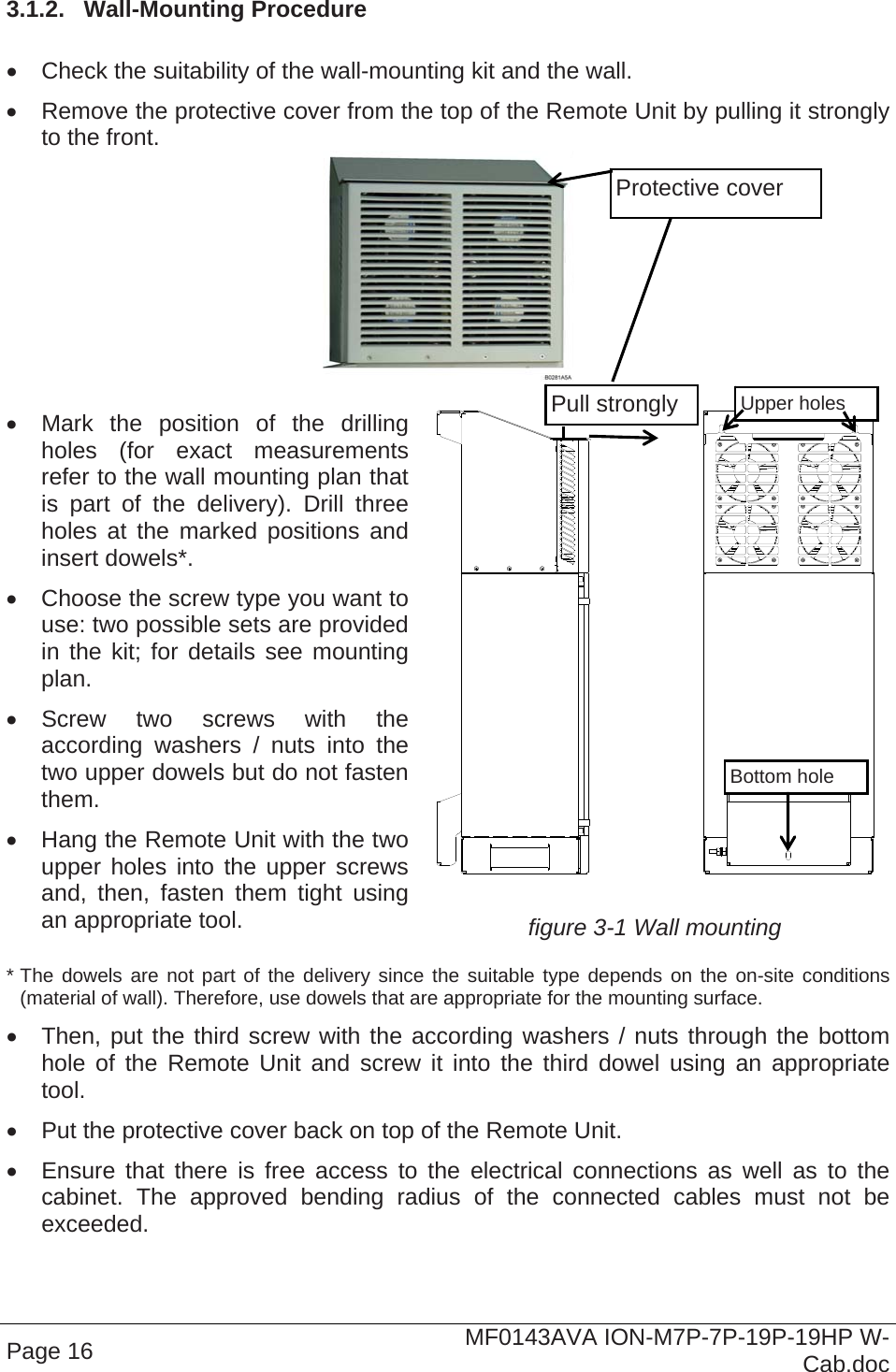
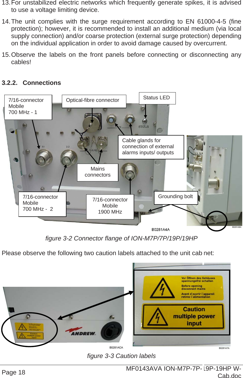
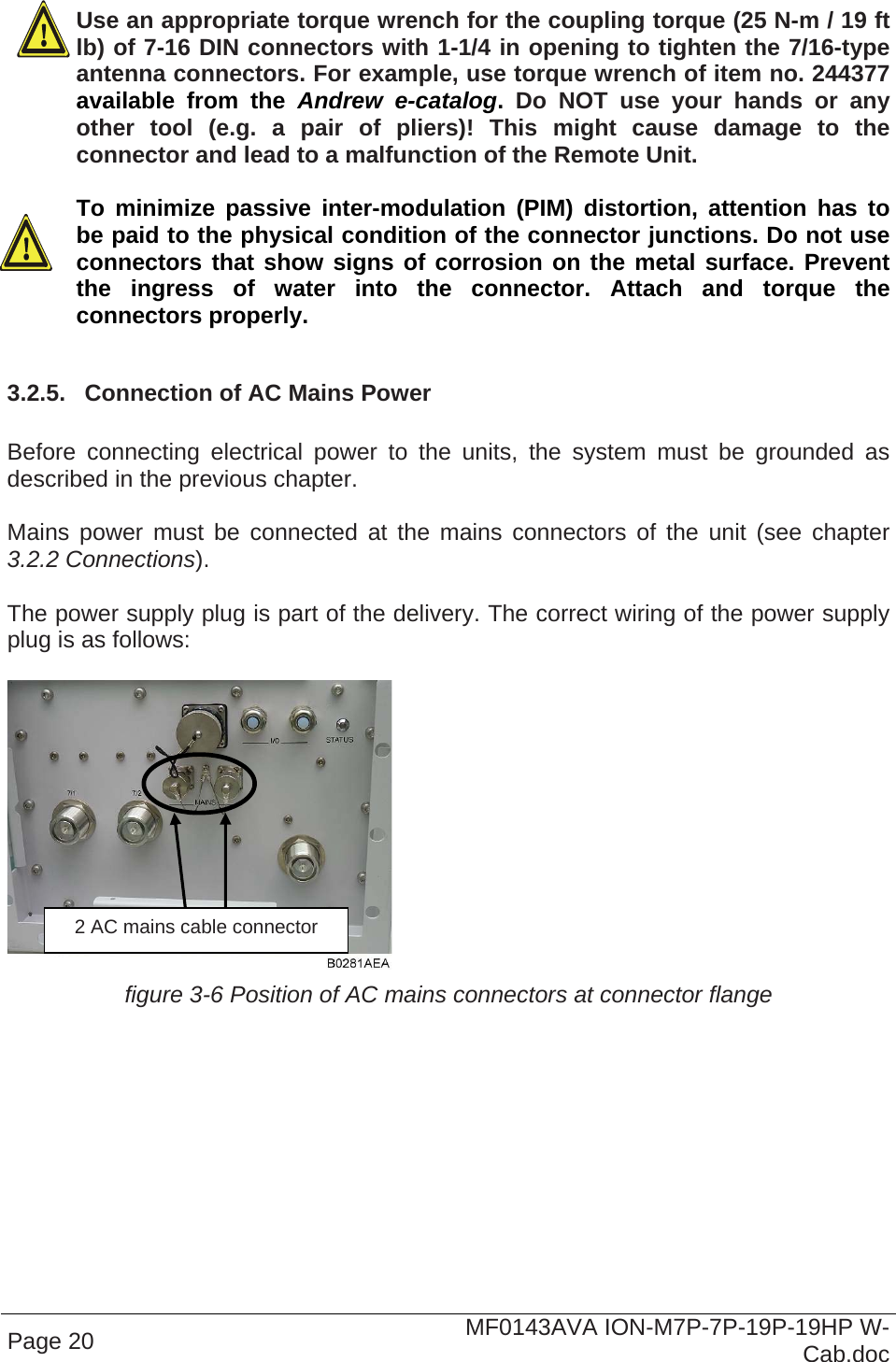
User Manual
Discussion / Help
Navigation