Andrew Wireless System M78517E19P ION-M Remote Unit for cellular systems User Manual MF0150A2A
Andrew Wireless System ION-M Remote Unit for cellular systems MF0150A2A
Contents
- 1. Installation Instruction
- 2. user manual
user manual
ION®-M7P/85P/17EP/19P
Optical Remote Unit
(M2-Cabinet)
Manual
MF0150A2A

Page 2 MF0150A2A.doc Manual for ION-M7P/85P/17EP/19P
DISCLAIMER:
This document has been developed by CommScope, and is intended for the use of its
customers and customer support personnel. The information in this document is subject to
change without notice. While every effort has been made to eliminate errors, CommScope
disclaims liability for any difficulties arising from the interpretation of the information
contained herein. The information contained herein does not claim to cover all details or
variations in equipment, nor to provide for every possible incident to be met in connection
with installation, operation, or maintenance. This document describes the performance of the
product under the defined operational conditions and does not cover the performance under
adverse or disturbed conditions. Should further information be desired, or should particular
problems arise which are not covered sufficiently for the purchaser’s purposes, contact
CommScope.
CommScope reserves the right to change all hardware and software characteristics without
notice.
COPYRIGHT:
© Copyright 2016 CommScope Inc. All Rights Reserved.
This document is protected by copyright. No part of this document may be reproduced,
stored in a retrieval system, or transmitted, in any form or by any means, electronic,
mechanical photocopying, recording, or otherwise without the prior written permission of
CommScope.
TRADEMARKS
All trademarks identified by ® or ™ are registered trademarks or trademarks, respectively, of
CommScope. Names of products mentioned herein are used for identification purposes only
and may be trademarks and / or registered trademarks of their respective companies.
Andrew Wireless Systems GmbH, 01-April-2016

Table of Contents
MF0150A2A.doc Manual for ION-
M7P/85P/
17EP
/19P
Page 3
TABLE OF CONTENTS
1.GENERAL 5
1.1.USED ABBREVIATIONS 5
1.2.HEALTH AND SAFETY 6
1.3.PROPERTY DAMAGE WARNINGS 6
1.4.COMPLIANCE 7
1.5.ABOUT COMMSCOPE 11
1.6.INTERNATIONAL CONTACT ADDRESSES FOR CUSTOMER SUPPORT 12
2.INTRODUCTION 14
2.1.PURPOSE 14
2.2.THE ION-M7P/85P/17EP/19P 14
3.FUNCTIONAL DESCRIPTION 16
4.COMMISSIONING 18
4.1.MECHANICAL INSTALLATION 19
4.1.1.Health and Safety for Mechanical Installation 19
4.1.2.Property Damage Warnings for Mechanical Installation 19
4.1.3.Wall-Mounting Procedure 21
4.1.4.Pole Mounting with screw bands 22
4.1.5.Pole mounting procedure with brackets 23
4.2.ELECTRICAL INSTALLATION 25
4.2.1.Health and Safety for Electrical Installation 25
4.2.2.Property Damage Warnings for Electrical Installation 25
4.2.3.Connections 26
4.2.4.Grounding (Earthing) 28
4.2.5.Connection of the Antenna Cables 28
4.2.6.Cleaning Procedure for RF Cable Connectors 29
4.2.7.Antenna Cable Connector Assembly 32
4.2.8.Optical-Fiber-Cable Connection - Rules 33
4.2.9.Protective Plug 35
4.2.10.Protective-Tube Kit 37
4.2.11.Mains Power Connection 38
4.2.11.1.Mains power connection AC 38
4.2.11.2.Mains power connection DC 39
4.2.12.External Alarm Inputs and Outputs 42
4.2.13.Commisioning Flowchart 45
5.ALARMS AND TROUBLESHOOTING 47
6.MAINTENANCE 48
6.1.GENERAL 48
6.2.REPLACING THE FAN UNIT 49
6.3.CLEANING THE HEAT SINK 50

Figures and Tables
Page 4 MF0150A2A.doc Manual for ION-M7P/85P/17EP/19P
7.APPENDIX 51
7.1.ILLUSTRATIONS 51
7.2.SPECIFICATIONS 52
7.2.1.SW Requirements 52
7.2.2.Electrical Specifications 52
7.2.3.Environmental and Safety Specifications 52
7.2.4.Mechanical Specifications 52
7.3.SPARE PARTS 53
8.INDEX 54
FIGURES AND TABLES
figure 3-1 Configuration of an ION-M7P/85P/17EP/19P, combined antenna port ..... 16
figure 3-2 Configuration of an ION-M7P/85P/17EP/19P with separate antenna ports
high low band ........................................................................................... 16
figure 3-3 System overview for an ION-M7P/85P/17EP/19P Remote Unit ................ 17
figure 4-1 Wall mounting - pitches .............................................................................. 21
figure 4-2 Pole mounting - pitches .............................................................................. 22
figure 4-3 Pole mounting - screw bands ..................................................................... 22
figure 4-4 Pole mounting - fasten RU ......................................................................... 22
figure 4-5 Pole mounting – max. diameter ................................................................. 23
figure 4-6 Pole mounting – with brackets ................................................................... 23
figure 4-7 Pole mounting - pitches .............................................................................. 24
figure 4-8 Pole mounting - brackets ........................................................................... 24
figure 4-9 Pole mounting - fasten RU ......................................................................... 24
figure 4-10 Connector flange of ION-M7P/85P/17EP/19P, AC version with 2 antenna
ports ......................................................................................................... 26
figure 4-11 Connector flange of ION-M7P/85P/17EP/19P, DC version with 2 antenna
ports ......................................................................................................... 27
figure 4-12 DC Connector of ION-M7P/85P/17EP/19P ............................................. 27
figure 4-13 Grounding bolt .......................................................................................... 28
figure 4-14 Grounding bolt, schematic view ............................................................... 28
figure 4-15 Protective-plug assembly ......................................................................... 35
figure 4-16 Tube-kit installation .................................................................................. 37
figure 4-17 Mains power connector ............................................................................ 38
figure 4-18 Mains power cable - AC ........................................................................... 38
figure 4-19 Flange connector, 5 poles ........................................................................ 43
figure 4-20 Alarm inputs (optocoupler) ....................................................................... 43
figure 4-21 Alarm outputs (optocoupler) ..................................................................... 44
figure 4-22 Flange connector, 7 poles ........................................................................ 44
figure 7-1 Cabinet drawing ......................................................................................... 51
table 1-1 List of international contact addresses ........................................................ 13
table 4-1 Specified torques ......................................................................................... 20
table 4-2 AC power cable pinning .............................................................................. 39
table 5-1 Status LED alarms ....................................................................................... 47

1. General
MF0150A2A.doc Manual for ION-
M7P/85P/
17EP
/19P
Page 5
1. General
1.1. Used Abbreviations
3GPP 3rd Generation Partnership Project
AC/DC Alternating current / Direct Current
AIMOS Andrew Integrated Management and Operating System
ALC Automatic Level Control
BITE Built-In Test Equipment
BTS Base Transceiver Station
CE "Conformité Européenne" ("European Conformity")
CD Compact Disk
CFR Code of Federal Regulations
DL Downlink
DoC Declaration of Conformity
EDGE Enhanced Data Rates for GSM Evolution
EN European Norm
ESD Electrostatic Discharge
ETS European Telecommunication Standard
GSM Global System for Mobile Communication
GND Ground
GUI Graphical User Interface
ICP3 Intercept Point 3rd order
ID No Identification Number
ION Intelligent Optical Network
IP Ingress Protection
ISO International Organization for Standardization
LED Light Emitting Diode
LMT Local Maintenance Terminal
LTE Long Term Evolution
MIMO Multiple Input Multiple Output
MS Mobile Station
MU Main Unit
NF Noise Figure
OTRx Optical Transceiver = SRMU (Subrack Master Unit)
PG Packing Gland
PIM Passive Intermodulation
R&TTE Radio & Telecommunications Terminal Equipment
RF Radio Frequency
RU Remote Unit
RX Receiver
SNMP Simple Network Management Protocol
TX Transmitter
UL Uplink
UMTS Universal Mobile Telecommunication System
UPS Uninterruptible Power Supply
WCDMA Wideband Code Division Multiple Access
WDM Wavelength Division Multiplex
1. General
Page 6 MF0150A2A.doc Manual for ION-M7P/85P/17EP/19P
1.2. Health and Safety
1. Danger: Electrical hazard. Danger of death or fatal injury from electrical
current. Obey all general and regional installation and safety regulations
relating to work on high voltage installations, as well as regulations
covering correct use of tools and personal protective equipment.
2. Danger: Electrical hazard. Danger of death or fatal injury from electrical
current inside the unit in operation. Before opening the unit, disconnect
mains power.
3. Caution: Laser radiation. Risk of eye injury in operation. Do not stare into the
beam; do not view it directly or with optical instruments.
4. Caution: High frequency radiation in operation. Risk of health hazards associated
with radiation from the unit’s inner conductor of the antenna port(s). Disconnect
mains before connecting or replacing antenna cables.
5. Caution: High frequency radiation in operation. Risk of health hazards associated
with radiation from the antenna(s) connected to the unit. Implement prevention
measures to avoid the possibility of close proximity to the antenna(s) while in
operation.
1.3. Property Damage Warnings
1. Attention: Due to power dissipation, the remote unit may reach a very high
temperature. Do not operate this equipment on or close to flammable materials.
Use caution when servicing the unit.
2. Attention: Only authorized and trained personnel are allowed to open the unit
and get access to the inside.
3. Notice: Although the Remote Unit is internally protected against overvoltage, it is
strongly recommended to ground (earth) the antenna cables close to the antenna
connectors of the Remote Unit for protection against atmospheric discharge. In
areas with strong lightning, it is strongly recommended to install additional
lightning protection.
4. Notice: ESD precautions must be observed. Before commencing maintenance
work, use the available grounding (earthing) system to connect ESD protection
measures.
5. Notice: Only suitably qualified personnel are allowed to work on this unit and only
after becoming familiar with all safety notices, installation, operation and
maintenance procedures contained in this manual.
6. Notice: Keep operating instructions within easy reach and make them available
to all users.
1. General
MF0150A2A.doc Manual for ION-
M7P/85P/
17EP
/19P
Page 7
7. Notice: Read and obey all the warning labels attached to the unit. Make sure that
all warning labels are kept in a legible condition. Replace any missing or
damaged labels.
8. Notice: Only license holders for the respective frequency range are allowed to
operate this unit.
9. Notice: Make sure the repeater settings are correct for the intended use (refer to
the manufacturer product information) and regulatory requirements are met. Do
not carry out any modifications or fit any spare parts, which are not sold or
recommended by the manufacturer.
1.4. Compliance
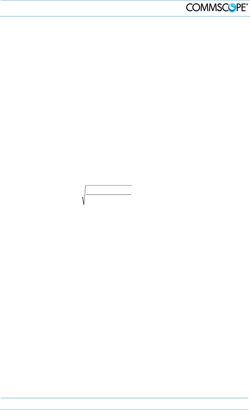
1. Notice: For installations, which have to comply with FCC RF exposure
requirements, the antenna selection and installation must be completed in a way
to ensure compliance with those FCC requirements. Depending on the RF
frequency, rated output power, antenna gain, and the loss between the repeater
and antenna, the minimum distance D to be maintained between the antenna
location and human beings is calculated according to this formula:
]/[
][
][
2
4cmmW
mW
cm PD
P
D
where
P (mW) is the radiated power at the antenna, i.e. the max. rated repeater
output power in addition to the antenna gain minus the loss between the
repeater and the antenna.
PD (mW/cm²) is the allowed Power Density limit acc. to 47 CFR 1.1310 (B)
for general population / uncontrolled exposures which is
o F (MHz) / 1500 for frequencies from 300MHz to 1500MHz
o 1 for frequencies from 1500MHz to 100,000MHz
RF exposure compliance may need to be addressed at the time of licensing, as
required by the responsible FCC Bureau(s), including antenna co-location
requirements of 1.1307(b)(3).
2. Notice: For installations which have to comply with European EN50385 exposure
compliance requirements, the following Power Density limits/guidelines (mW/cm²)
according to ICNIRP are valid:
o 0.2 for frequencies from 10 MHz to 400 MHz
o F (MHz) / 2000 for frequencies from 400 MHz to 2 GHz
o 1 for frequencies from 2 GHz to 300 GHz

1. General
Page 8 MF0150A2A.doc Manual for ION-M7P/85P/17EP/19P
3. Notice: For installations which have to comply with FCC/Industry Canada
requirements:
English:
This device complies with FCC Part 15. Operation is subject to the following two
conditions: (1) this device may not cause interference, and (2) this device must accept
any interference, including interference that may cause undesired operation of the
device.
This device complies with Health Canada’s Safety Code. The installer of this device
should ensure that RF radiation is not emitted in excess of the Health Canada’s
requirement. Information can be obtained at http://www.hc-sc.gc.ca/ewh-
semt/pubs/radiation/radio_guide-lignes_direct-eng.php.
Changes or modifications not expressly approved by the party responsible for
compliance could void the user’s authority to operate the equipment.
Antenna Stmt for Industry Canada:
This device has been designated to operate with the antennas having a maximum gain
of 9 dBi. Antennas having a gain greater than 9 dBi are prohibited for use with this
device without consent by Industry Canada regulators. The required antenna impedance
is 50 ohms.
The antenna(s) used for this transmitter must be installed to provide a separation
distance of at least 100 cm from all persons and must not be co-located or operating in
conjunction with any other antenna or transmitter. Users and installers must be provided
with antenna installation instructions and transmitter operating conditions for satisfying
RF exposure compliance.
French:
Cet appareil est conforme à FCC Partie15. Son utilisation est soumise à Les deux
conditions suivantes: (1) cet appareil ne peut pas provoquer d’interférences et (2) cet
appareil doit accepter Toute interférence, y compris les interférences qui peuvent causer
un mauvais fonctionnement du dispositif.
Cet appareil est conforme avec Santé Canada Code de sécurité 6. Le programme
d’installation de cet appareil doit s’assurer que les rayonnements RF n’est pas émis au-
delà de I’exigence de Santé Canada. Les informations peuvent être obtenues:
http://www.hc-sc.gc.ca/ewh-semt/pubs/radiation/radio_guide-lignes_direct-fra.php
Les changements ou modifications non expressément approuvés par la partie
responsable de la conformité pourraient annuler l’autorité de l’utilisateur à utiliser cet
équipement.
Antenne Stmt pour Industrie Canada:
Ce dispositif a été désigné pour fonctionner avec les antennes ayant un gain maximal de
9 dBi. Antennes ayant un gain plus grand que 9 dBi sont interdites pour une utilisation
avec cet appareil sans le consentement des organismes de réglementation d’Industrie
Canada. L’impédance d’antenne requise est 50 ohms.
L’antenne (s) utilisé pour cet émetteur doit être installé pour fournir une distance de
séparation d’au moins 100 cm de toutes les personnes et ne doit pas être co-localisées
ou opérant en conjonction avec une autre antenne ou émetteur. Les utilisateurs et les
installateurs doivent être fournis avec des instructions d’installation de l’antenne et des
conditions de fonctionnement de l’émetteur pour satisfaire la conformité aux expositions
RF.

1. General
MF0150A2A.doc Manual for ION-
M7P/85P/
17EP
/19P
Page 9
4. Notice: Installation of this equipment is in full responsibility of the installer, who
has also the responsibility, that cables and couplers are calculated into the
maximum gain of the antennas, so that this value, which is filed in the FCC Grant
and can be requested from the FCC data base, is not exceeded. The industrial
boosters are shipped only as a naked booster without any installation devices or
antennas as it needs for professional installation.
5. Notice: The unit complies with Overvoltage Category II. It also complies with the
surge requirement according to EN 61000-4-5 (fine protection); however,
installation of an additional medium (via local supply connection) and/or coarse
protection (external surge protection) is recommended depending on the
individual application in order to avoid damage caused by overcurrent.
For Canada and US, components used to reduce the Overvoltage Category shall
comply with the requirements of IEC 61643-series. As an alternative, components
used to reduce the Overvoltage Category may comply with ANSI/IEEE C62.11,
CSA Certification Notice No. 516, CSA C22.2 No. 1, or UL 1449. Suitability of the
component for the application shall be determined for the intended installation.
6. Notice: Corresponding local particularities and regulations must be observed. For
national deviations, please refer to the respective documents included in the
manual CD that is delivered with the unit.
7. Note: For a Class A digital device or peripheral:
This equipment has been tested and found to comply with the limits for a Class A
digital device, pursuant to part 15 of the FCC Rules. These limits are designed to
provide reasonable protection against harmful interference when the equipment is
operated in a commercial environment. This equipment generates, uses, and can
radiate radio frequency energy and, if not installed and used in accordance with
the instruction manual, may cause harmful interference to radio communications.
Operation of this equipment in a residential area is likely to cause harmful
interference in which case the user will be required to correct the interference at
his own expense.
8. Note: For a Class B digital device or peripheral:
This equipment has been tested and found to comply with the limits for a Class B
digital device, pursuant to part 15 of the FCC Rules. These limits are designed to
provide reasonable protection against harmful interference in a residential
installation. This equipment generates, uses and can radiate radio frequency
energy and, if not installed and used in accordance with the instructions, may
cause harmful interference to radio communications. However, there is no
guarantee that interference will not occur in a particular installation. If this
equipment does cause harmful interference to radio or television reception, which
can be determined by turning the equipment off and on, the user is encouraged to
try to correct the interference.
9. Note: This unit complies with European standard EN60950.
1. General
Page 10 MF0150A2A.doc Manual for ION-M7P/85P/17EP/19P
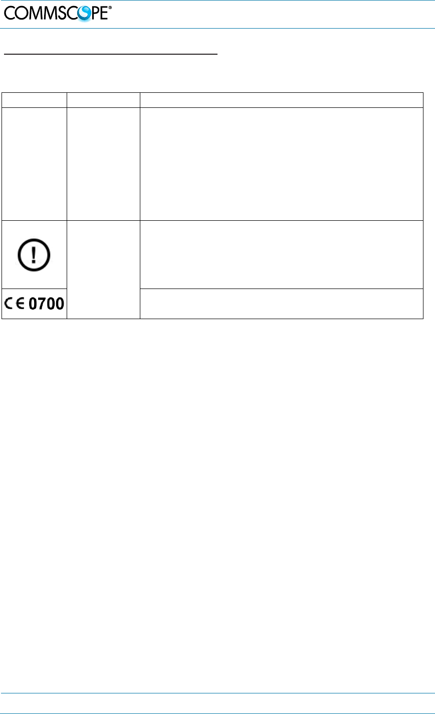
Equipment Symbols Used / Compliance
Please observe the meanings of the following symbols used in our equipment and
the compliance warnings:
Symbol Compliance Meaning / Warning
--- FCC
For industrial (Part 20) signal booster:
WARNING: This is NOT a CONSUMER device. It is
designed for installation by FCC LICENSEES and
QUALIFIED INSTALLERS. You MUST have an FCC
LICENSE or express consent of an FCC Licensee to
operate this device. Unauthorized use may result in
significant forfeiture penalties, including penalties in
excess of $100,000 for each continuing violation.
CE
Alert sign to R&TTE
To be sold exclusively to mobile operators or
authorized installers – no harmonized frequency
bands, operation requires license. Intended use: EU
and EFTA countries.
Indicates conformity with the R&TTE directive
1999/5/EC certified by the notified body no. 0700.

1. General
MF0150A2A.doc Manual for ION-
M7P/85P/
17EP
/19P
Page 11
1.5. About CommScope
CommScope is the foremost supplier of one-stop, end-to-end radio frequency (RF)
solutions. Part of the CommScope portfolio are complete solutions for wireless
infrastructure from top-of-the-tower base station antennas to cable systems and
cabinets, RF site solutions, signal distribution, and network optimization. For patents
see www.cs-pat.com.
CommScope has global engineering and manufacturing facilities. In addition, it
maintains field engineering offices throughout the world.
Andrew Wireless Systems GmbH based in Buchdorf/Germany, which is part of
CommScope, is a leading manufacturer of coverage equipment for mobile radio
networks, specializing in high performance, RF and optical repeaters. Our optical
distributed networks and RF repeater systems provide coverage and capacity
solution for wireless networks in both indoor installations and outdoor environments,
e.g. tunnels, subways, in-trains, airport buildings, stadiums, skyscrapers, shopping
malls, hotels and conference rooms.
Andrew Wireless Systems GmbH operates a quality management system in
compliance with the requirements of ISO 9001 and TL 9000. All equipment is
manufactured using highly reliable material. To maintain highest quality of the
products, comprehensive quality monitoring is conducted at all fabrication stages.
Finished products leave the factory only after a thorough final acceptance test,
accompanied by a test certificate guaranteeing optimal operation.
This product meets the requirements of the R&TTE directive and the Declaration of
Conformity (DoC) itself. A current version of the CE DoC is included in this manual
CD delivered *. Any updated version of the DoC is available upon request from the
local sales offices or directly from CommScope via the local Customer Support at
one of the addresses listed in the following chapter.
According to the DoC, our "CE"-marked equipment can be used in all member
states of the European Union.
Note: Exceptions of and national deviations from this intended use may be
possible. To observe corresponding local particularities and
regulations, please refer to the respective documents (also in
national language) which are included in the manual CD delivered.
* In case the Declaration of Conformity (DoC) for the product was not included in the manual CD
delivered, it is available upon request from the local sales offices or directly from CommScope at
one of the addresses listed in the following chapter.
To make the most of this product, we recommend you carefully read the instructions
in this manual and commission the system only according to these instructions.
For technical assistance and support, please also contact the local office or
CommScope directly at one of the addresses listed in the following chapter.

1. General
Page 12 MF0150A2A.doc Manual for ION-M7P/85P/17EP/19P
1.6. International Contact Addresses for Customer Support
Canada
A
M
E
R
I
C
A
S
United States
CommScope Canada
A
ndrew LLC, A CommScope Company
Mail 505 Consumers Road, Suite 803
Toronto M2J 4V8, Canada Mail 620 North Greenfield Parkway
Garner, NC 27529, U.S.A.
Phone +1-905-878-3457 (Office)
+1-416-721-5058
(
Cell
)
Phone +1-888-297-6433
Fax +1-905-878-3297 Fax +1-919-329-8950
E-mail wisupport@commscope.com E-mail wisupport@commscope.com
Caribbean & South American Region Caribbean & Central American Region
CommScope Cabos do Brasil Ltda. CommScope Mexico S.A. de C.V.
Mail
CALA Tech Support for Distributed
Coverage & Capacity Solutions (DCCS)
products:
Rua Guaporanga, 49
Praça Seca – Rio de Janeiro – RJ
ZIP: 21320-180, Brazil
Mail
CALA Tech Support for Distributed
Coverage & Capacity Solutions
(DCCS) products:
Av. Insurgentes Sur 688, Piso 6
Col. Del Valle, CP: 03100
Mexico City, Mexico
Phone +1-815-546-7154 (Cell)
+55-15-9104-7722 (Office) Phone +52-55-1346-1900 (Office)
Fax + 55-15-2102-4001 Fax +52-55-1346-1901
E-mail wisupport@commscope.com E-mail wisupport@commscope.com
China, India and Rest of Asia
A
P
A
C
Australia & New Zealand
Andrew International Corporation
A
ndrew Corporation (Australia) Pty Ltd.
Mail
Room 915, 9/F
Chevalier Commercial Centre
8 Wang Hoi Rd
Kowloon Bay, Hong Kong
Mail
Unit 1
153 Barry Road
Campbellfield
VIC 3061, Australia
Phone +852-3106-6100 Phone +613-9300-7969
Fax +852-2751-7800 Fax +613-9357-9110
E-mail wisupport.China@commscope.com E-mail wisupport.Australia@commscope.com
Middle East & North Africa
Africa
&
Middle
East
South Africa
CommScope Solutions International Inc.
(Branch)
A
ndrew Wireless Solutions Africa
(PTY) LTD
Mail
PO Box 48 78 22
Unit 3206, Floor 32,
Jumeirah Business Center 5,
Jumeirah Lakes Towers,
Dubai, United Arab Emirates
Mail
11 Commerce Crescent West
Eastgate, Sandton
PO Box 786117
Sandton 2146
South Africa
Phone +971 4 390 09 80 Phone + 27 11-719-6000
Fax +971 4 390 86 23 Fax + 27 11-444-5393
E-mail wisupport@commscope.com E-mail wisupport@commscope.com
1. General
MF0150A2A.doc Manual for ION-
M7P/85P/
17EP
/19P
Page 13
United Kingdom
E
U
R
O
P
E
Scandinavia
Andrew Wireless Systems UK Ltd
A
ndrew Norway (AMNW)
Mail
Unit 15, Ilex Building
Mulberry Business Park
Fishponds Road
Wokingham Berkshire
RG41 2GY, England
Mail
P.O. Box 3066
Osloveien 10
Hoenefoss 3501
Norway
Phone +44-1189-366-792 Phone + 47 32-12-3530
Fax +44-1189-366-773 Fax + 47 32-12-3531
E-mail wisupport.uk@commscope.com E-mail wisupport@commscope.com
Germany France
Andrew Wireless Systems GmbH CommScope France
Mail
Industriering 10
86675 Buchdorf
Germany
Mail
Immeuble Le Lavoisier
4, Place des Vosges
92052 Courbevoie, France
Phone +49-9099-69-0 Phone +33-1 82 97 04 00
Fax +49-9099-69-930 Fax +33-1 47 89 45 25
E-mail wisupport
@
commscope.com E-mail wisupport
@
commscope.com
Austria Switzerland
Andrew Wireless Systems (Austria) GmbH CommScope Wireless Systems AG
Mail
Weglgasse 10
2320 Wien-Schwechat
Austria
Mail
Tiergartenweg 1
CH-4710 Balsthal
Switzerland
Phone +43-1706-39-99-10 Phone +41-62-386-1260
Fax +43-1706-39-99-9 Fax +41-62-386-1261
E-mail wisupport.austria@commscope.com E-mail wisupport.ch@commscope.com
Italy Iberia Region - Spain & Portugal
CommScope Italy S.r.l., Faenza, Italy
A
ndrew España S.A.
A
CommScope Company
Mail
Via Mengolina, 20
48018 Faenza (RA)
Italy
Mail
Avda. de Europa, 4 - 2ª pta.
Parque Empresarial de la Moraleja
Alcobendas, Madrid 28108, Spain
Phone +39-0546-697111 Phone +34-91-745-20 40
Fax +39-0546-682768 Fax +34-91-661-87 02
E-mail wisupport.italia@commscope.com E-mail wisupport.iberia@commscope.com
Czech Republic
CommScope Solutions Czech Republic
C-Com, spol. s r.o
Mail U Moruší 888
53006 Pardubice, Czech Republic
Phone +49 871 9659171 (Office)
+49 171 4001166 (Mobile)
Fax +49 871 9659172
E-mail wisupport@commscope.com
table 1-1 List of international contact addresses

2. Introduction
Page 14 MF0150A2A.doc Manual for ION-M7P/85P/17EP/19P
2. Introduction
2.1. Purpose
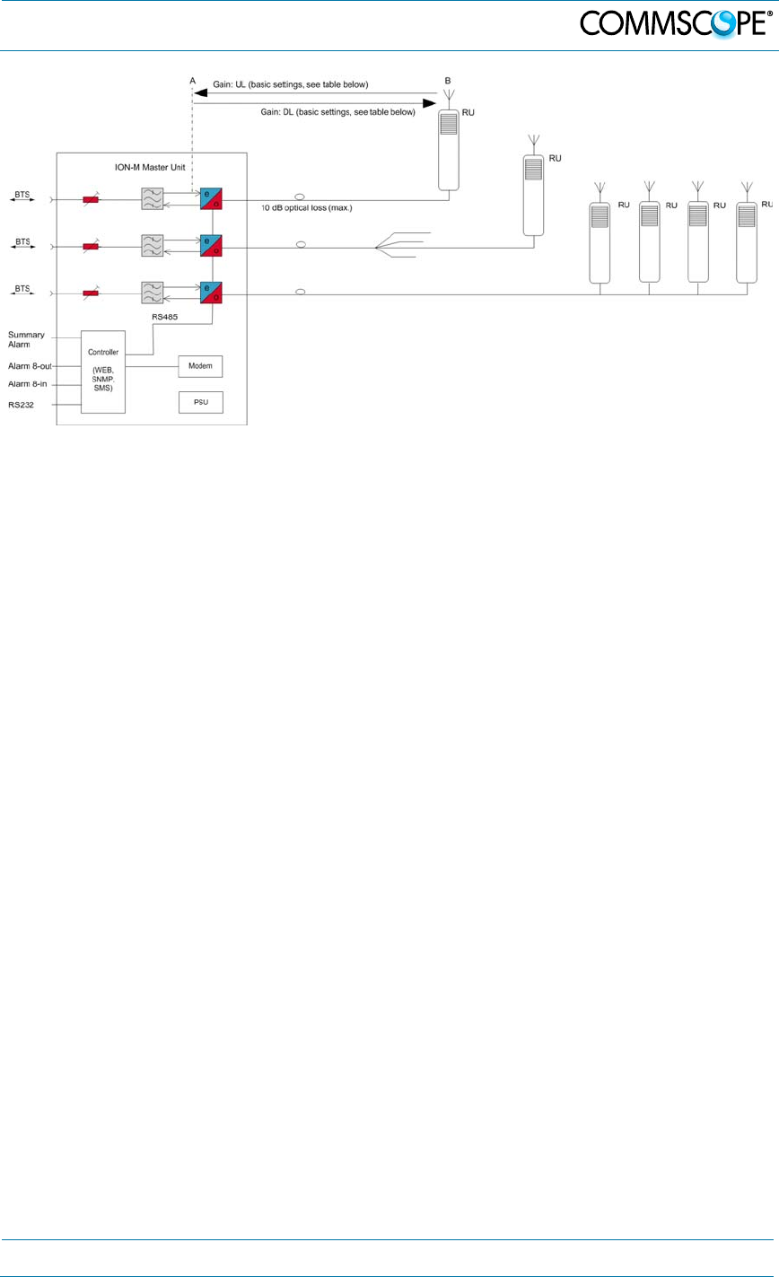
Cellular telephone systems transmit signals in two directions between base
transceiver station (BTS) and mobile stations (MS) within the signal coverage area.
If weak signal transmissions occur within the coverage area because of indoor
applications, topological conditions or distance from the transmitter, extension of the
transmission range can be achieved by means of an optical distribution system.
Such a system contains an optical Master Unit and several Remote Units. The
number of the Remote Units depends on the hardware and software configuration.
The Remote Units are connected to the Master Unit with optical links. The optical
loss must be less than 10 dB inclusive optical couplers or splitters.
The Master Unit is the connection to the base transceiver stations. The configuration
of a Master Unit depends on the number of the Remote Units and the frequency
range.
WDM (Wave Division Multiplex) filters are integrated in the optical modules. For the
UL, a wavelength within 1546 nm – 1550 nm is used. For the DL, a wavelength of
1310 ± 10 nm is used. The maximum output power for the UL and DL is 6.7 mW.
2.2. The ION-M7P/85P/17EP/19P
The ION-M7P/85P/17EP/19P is a multi-band, multi-operator Remote Unit
configuration used in conjunction with a Master Unit in the ION optical distribution
system. By supporting the entire AWS-3 spectrum, faster and more reliable wireless
service is ensured and network quality can be improved.
This system transports up to four frequency bands simultaneously (700 MHz, 850
MHz, 1700/2100 MHz, 1900 MHz), providing a cost-effective solution for distributing
capacity from one or more base stations.
The ION system transports signals on the RF layer in a very cost-effective manner
enabling multiple operators to use multiple technologies and move their signals
simultaneously from a cluster of base station to a number of remote locations over
the same fiber.
The ION-M optical distribution system is a cost-effective coverage solution for dense
urban areas, tunnels, subways, airports, convention centers, high-rise buildings and
other locations where physical structures increase path loss.
The combination of these units gives maximum flexibility while providing a scalable
solution. The system is optimized for GSM, LTE, CDMA and WCDMA signals in the
700 MHz, 850 MHz, 1900 MHz and 1700/2100 MHz bands. Furthermore it is
provisioned for future modulation schemes and frequency bands.

2. Introduction
MF0150A2A.doc Manual for ION-
M7P/85P/
17EP
/19P
Page 15
The ION can be easily set-up and supervised from a graphical user interface (GUI).
Remote units are commissioned through the use of built-in test equipment. An auto
leveling function compensates for the optical link loss making installation easy and
quick.
The entire system as well as complete network of systems can be managed remotely
most efficiently by Commscope`s A.I.M.O.S, which includes alarm monitoring, task
automation, statistics, inventory management and ION-M7P/85P/17EP/19P many
more features. Should a sophisticated interface not be required, the Master Unit can
be directly connected to the alarm interface of a base station via its contact relay.
Reduced visual impact form factor
Optimized power consumption
Efficient, high power amplifier
Multi-operator support
Complete operations and management system for configuration and alarming
OMC with SNMP according to X.733 standard
With reference to 3GPP TS25.143/ TS25.106/36.143/TS36.106 and
3GPP2C.S0051-0
Single fiber for multiple bands and multiple remotes
Easy installation and commissioning
3. Functional Description
Page 16 MF0150A2A.doc Manual for ION-M7P/85P/17EP/19P
3. Functional Description
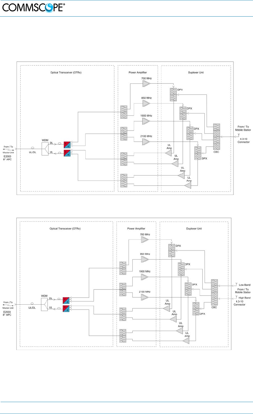
The following figure shows the general configuration of an ION-M7P/85P/17EP/19P
Remote Unit:
figure 3-1 Configuration of an ION-M7P/85P/17EP/19P, combined antenna port
figure 3-2 Configuration of an ION-M7P/85P/17EP/19P with separate antenna ports
high low band
3. Functional Description
MF0150A2A.doc Manual for ION-
M7P/85P/
17EP
/19P
Page 17
figure 3-3 System overview for an ION-M7P/85P/17EP/19P Remote Unit

4. Commissioning
Page 18 MF0150A2A.doc Manual for ION-M7P/85P/17EP/19P
4. Commissioning
Read and observe the health, safety, and property damage warnings as well as the
description carefully to avoid mistakes and proceed step-by-step as described.
Attention: Do not operate the Remote Unit without terminating the antenna
connectors. The antenna connectors may be terminated by connecting them
to their respective antennas or to a dummy load.
Notice: Only qualified personnel should carry out the electrical, mechanical,
commissioning, and maintenance activities that require the unit to be powered
on when open.
When opening the Remote Unit do not damage the warranty labels on the
internal devices. The warranty is void if the seals are broken.
One of the three mounting kits has to be ordered separately. They are not
contained within the standard equipment. See chapter 7.3
4. Commissioning
MF0150A2A.doc Manual for ION-
M7P/85P/
17EP
/19P
Page 19
Spare Parts.
Unless otherwise agreed to in writing by CommScope, CommScope’s general limited
product warranty (http://www.commscope.com/Resources/Warranties/) shall be the
warranty governing the Remote Units, including the installation, maintenance, usage
and operation of the Remote Units.
4.1. Mechanical Installation
4.1.1. Health and Safety for Mechanical Installation
1. Caution: Risk of injury by the considerable weight of the unit falling. Ensure there
is adequate manpower to handle the weight of the system.
2. Caution: Risk of serious personal injury by equipment falling due to improper
installation. The installer must verify that the supporting surface will safely
support the combined load of the electronic equipment and all attached hardware
and components. The screws and dowels (wall anchors) used should also be
appropriate for the structure of the supporting wall.
4.1.2. Property Damage Warnings for Mechanical Installation
1. Attention: Do not install the unit in a way or at a place where the specifications
outlined in the Environmental and Safety Specifications leaflet of the supplier are
not met.
2. Attention: Due to power dissipation, the Remote Unit may reach a very high
temperature. Ensure sufficient airflow for ventilation.
3. Notice: Exceeding the specified load limits may cause the loss of warranty.
4. Notice: When connecting and mounting the cables (RF, optical, mains, ...)
ensure that no water can penetrate into the unit through these cables.
5. Ensure that there is free access to the electrical connections as well as to the
cabinet. The approved bending radius of the connected cables must not be
exceeded. See chapter 7.1 for more details
4. Commissioning
Page 20 MF0150A2A.doc Manual for ION-M7P/85P/17EP/19P
6. Notice: If any different or additional mounting material is used, ensure that the
mounting remains as safe as the mounting designed by the manufacturer. The
specifications for stationary use of the Remote Unit must not be exceeded.
Ensure that the static and dynamic strengths are adequate for the environmental
conditions of the site. The mounting itself must not vibrate, swing or move in any
way that might cause damage to the Remote Unit.
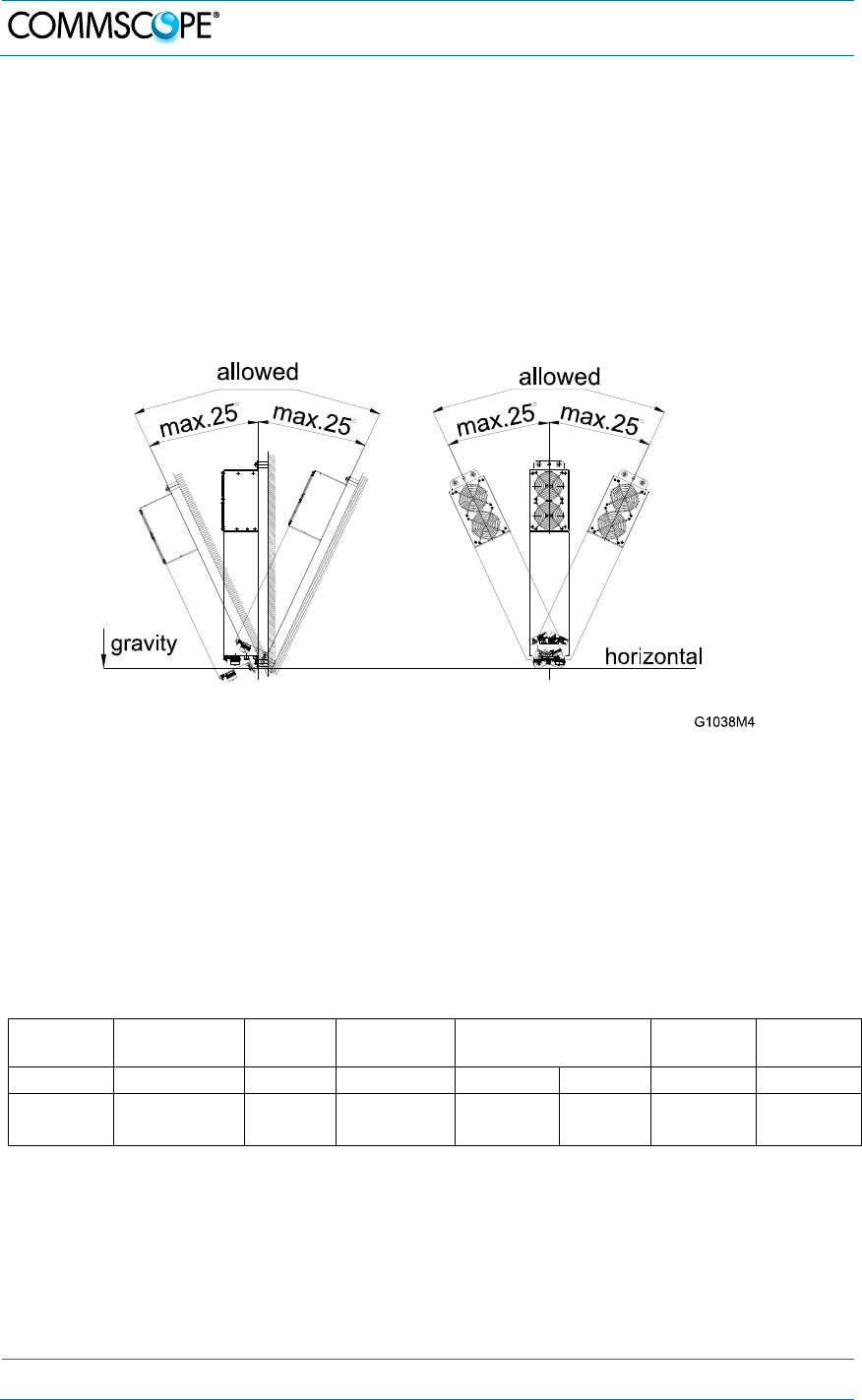
7. Notice: Observe all additional rules or restrictions regarding mounting that
depend on the type of Remote Unit. For details refer to section 7.2.2 Mechanical
Specification. Install the unit vertically with the fan unit at the top. A maximum tilt
angle of 25° from a vertical position must be kept, as in the following illustrations:
8. Notice: A spacing of 50 mm (1.97 inch) around the unit is required.
9. Notice: To ensure sufficient airflow when mounting the unit in enclosed spaces,
two lid openings (one for the air inlet and the other for the air outlet) must be
provided. Do not block these air inlets and outlets when mounting the Remote
Unit. The size of each opening must equal at least 18 x 18 cm (> 300 cm2).
Ensure that there is no thermal short circuit between the air inlet and air outlet.
Make sure free airflow is not deflected or otherwise obstructed.
Specified torques have to be observed for certain mounting procedures according to
the following table:
Type Tallow-drop
screws Hex
nuts Screw
band lock Spacing
bolts PG
(plastic) PG
(alum.)
Thread M 4 M 8 M 4 M 8 PG 13.5 PG 29
Specified
torques
3.3 N-m 27 N-m 6 N-m 2.3 N-m 27 N-m 3.75 N-m 10 N-m
table 4-1 Specified torques
4. Commissioning
MF0150A2A.doc Manual for ION-
M7P/85P/
17EP
/19P
Page 21
4.1.3. Wall-Mounting Procedure
Notice: It is the responsibility of the installer to verify that the supporting surface will
safely support the combined load of the electronic equipment and all attached
hardware and components and to ensure that the RU is safely and securely
mounted.
1. Mark the position of the drilling
holes (for pitches refer to figure
4-1 Wall mounting). Drill four
holes at the marked positions and
insert dowels*.
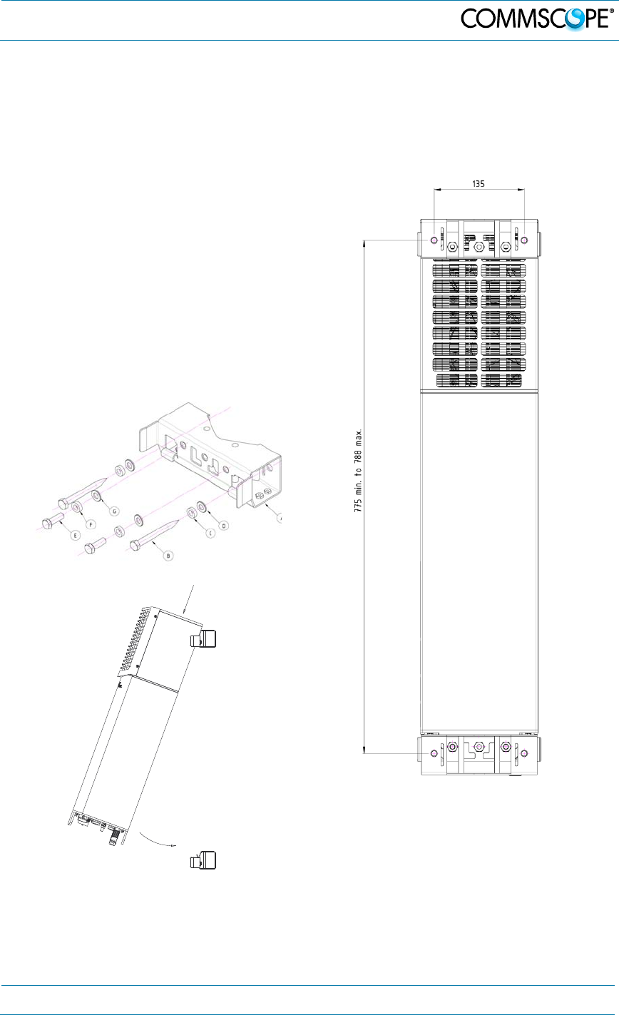
2. Mount the brackets (A) to the wall
using the M8x80 screws (B), split
lock washers (C), and washers
(D).
figure 4-1 Wall mounting - pitches
3. Hang the Remote Unit into the upper
bracket, insert it to the lower bracket, and
fasten it to the lower bracket with the
M8x25 screws (E), split lock washers (F),
and washers (G).
* The dowels are not included with the delivery because the suitable type depends on the on-site
conditions (material of wall).
4. Commissioning
Page 22 MF0150A2A.doc Manual for ION-M7P/85P/17EP/19P
4.1.4. Pole Mounting with screw bands
Standard mounting hardware cannot be used to mount the Remote Unit to a pole, a
column, or other similar structures. Additional hardware must be used for this type of
installation. The pole-mounting kit includes
two mounting brackets with screw bands, (worm gear) clamps to mount the
brackets to the pole
and two M8x25 screws, flat washers, and split lock washers per bracket to
attach the Remote Unit to the bracket.
775 min.
788 max.
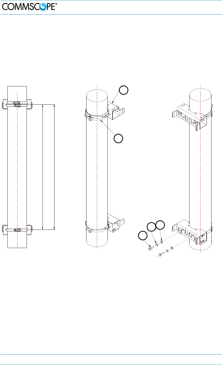
figure 4-2 Pole mounting
- pitches figure 4-3 Pole mounting
- screw bands figure 4-4 Pole mounting -
fasten RU
1. Use two screw bands (B) for the upper and one for the lower bracket to fasten the
two brackets (A) to the pole.
2. Place the bands around the pole or post and feed the loose end into the lock and
tighten the slotted screw securely. When the screw is turned clockwise, it acts as
a worm drive pulling the threads of the band causing the band to tighten around
the pole.
Note: When fastening the brackets make sure that they are installed congruently and
not at an angle to each other. To determine the distance between the clamps refer to
figure 4-2 Pole mounting - pitches.
A
B
C
DE
4. Commissioning
MF0150A2A.doc Manual for ION-
M7P/85P/
17EP
/19P
Page 23
3. Hang the Remote Unit into the upper bracket, insert it into the lower bracket, and
fasten it to the lower bracket with the M8x25 screws (C), split lock washers (D)
and washers (E), see chapter 4.1.3.
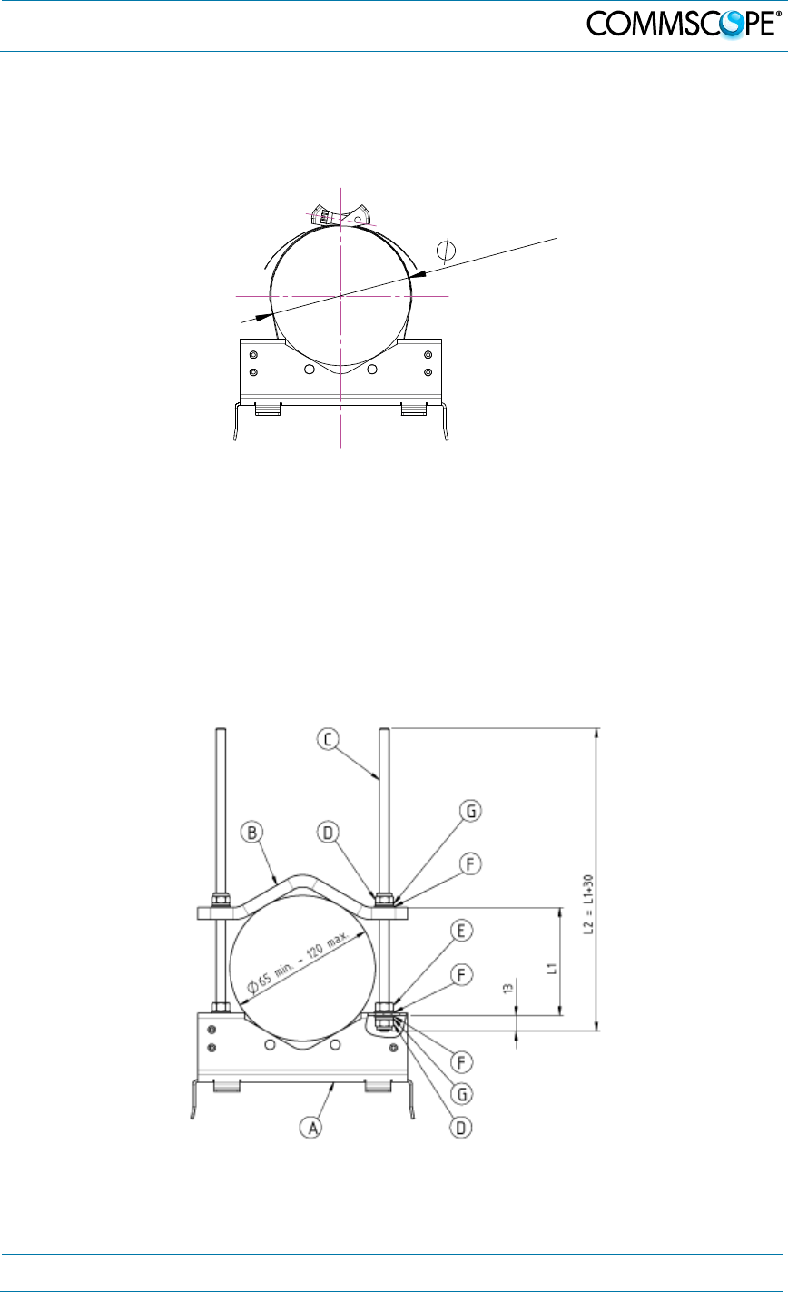
The maximum diameter of the pole or column must not exceed 120 mm (4.7 inch).
1
20m
ax.
figure 4-5 Pole mounting – max. diameter
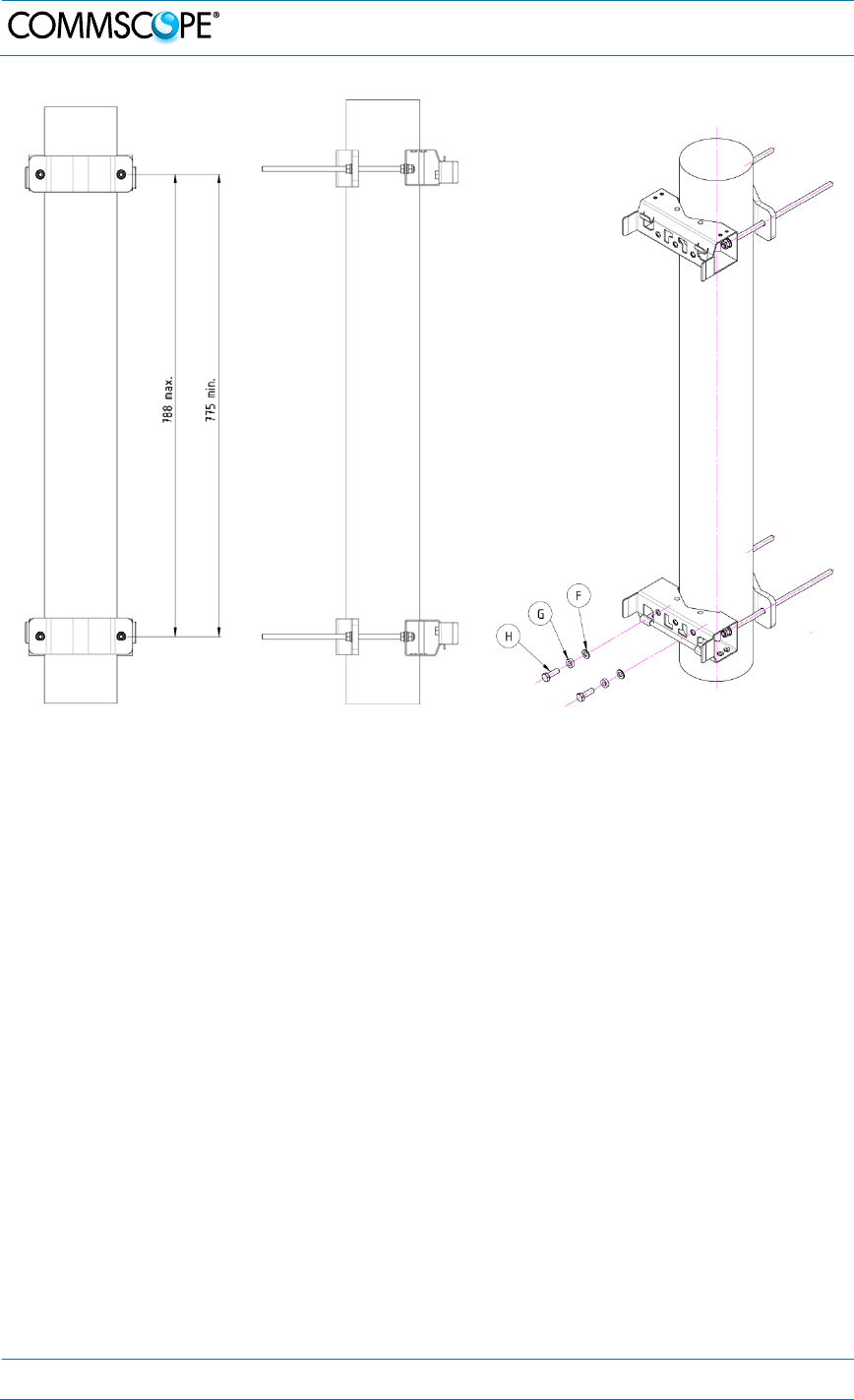
4.1.5. Pole mounting procedure with brackets
The pole-mounting kit with brackets includes
two mounting brackets (A), two counter brackets (B), four threaded bolts (C),
flat (F) and split lock (G) washers, hexagon (E) and locking (D) nuts to mount
the brackets to the pole
and two M8x25 screws (H), flat (F) and split lock (G) washers to attach the
Remote Unit to the bracket.
figure 4-6 Pole mounting – with brackets
4. Commissioning
Page 24 MF0150A2A.doc Manual for ION-M7P/85P/17EP/19P
figure 4-7 Pole
mounting - pitches figure 4-8 Pole
mounting - brackets figure 4-9 Pole mounting - fasten RU
1. Apply this procedure to both mounting brackets on both sides:
Screw a hexagon nut (E) to the threaded bolt and place a flat washer (F)) on it.
Insert this side of the bolt into the mounting bracket (A). Then, fasten the
mounting bracket with a flat washer (F), split lock washer (G), and the locking nut
(D). See figure 4-6 Pole mounting – with brackets.
2. Place the pre-mounted brackets with threaded bolts to the pole or post, slide the
counter bracket (B) on the threaded bolts and fasten the kit with a flat washer (F),
split lock washer (G), and the locking nut (D).
Note: When fastening the brackets make sure that they are installed
congruently and not at an angle to each other. To determine the distance
between the clamps refer to figure 4-7 Pole mounting - pitches.
3. Hang the Remote Unit into the upper bracket, insert it into the lower bracket (see
chapter 4.1.3), and fasten it to the lower bracket with the M8x25 screws (H), split
lock washers (G), and flat washers (F).
The diameter of the pole or column must be in the range from 65 to 120 mm (2.6 to
4.7 inch).

4. Commissioning
MF0150A2A.doc Manual for ION-
M7P/85P/
17EP
/19P
Page 25
4.2. Electrical Installation
4.2.1. Health and Safety for Electrical Installation
Read and observe chapter 1.2 Health and Safety.
Danger: Electrical hazard. Danger of death or fatal injury from electrical
current. Obey all general and regional installation and safety regulations
relating to work on high voltage installations, as well as regulations
covering correct use of tools and personal protective equipment.
4.2.2. Property Damage Warnings for Electrical Installation
1. Attention: It is compulsory to ground (earth) the unit before connecting the
power supply. Grounding bolts are provided on the cabinet to connect the
ground-bonding cable.
2. Attention: If the mains connector of the Remote Unit is not easily accessible, a
disconnect device in the mains power circuit must be provided within easy reach.
3. Attention: A connection of the mains supply to a power socket requires the
power socket to be nearby the Remote Unit.
4. Attention: Before connecting or disconnecting the mains connector at the
Remote Unit, ensure that mains power supply is disconnected.
5. Attention: Make sure that an appropriate circuit breaker acting as a disconnect
device (as required by IEC/EN60950-1) and an overcurrent limiting device are
connected between mains power and the Remote Unit.
6. Attention: Incorrectly wired connections can destroy electrical and electronic
components.
7. Notice: To avoid corrosion at the connectors caused by electrochemical
processes, the material of the cable connectors must not cause a higher potential
difference than 0.6 V (see electrochemical contact series).
8. Notice: Use an appropriate torque wrench for the coupling torques:
- for 7/16 DIN-type (25 N-m / 19 ft lb) with 1 ¼ in opening,
e. g. item no. 244377 available from the CommScope e-catalog
- for 4.3-10 type connectors (5 N-m, 44 in lb) with 22mm (7/8) in opening,
e.g. item no. TW-4310
9. Notice: : For unstabilized electric networks, which frequently generate spikes,
the use of a voltage limiting device is advised
10. Notice: Observe the labels on the front panels before connecting or
disconnecting any cables.
11. Notice: Unused connectors must be closed with their protective covers to ensure
watertightness.
4. Commissioning
Page 26 MF0150A2A.doc Manual for ION-M7P/85P/17EP/19P
4.2.3. Connections
The figures in this chapter show a connector flange with two antenna ports.
Optionally, a setup with only one antenna port is also available.
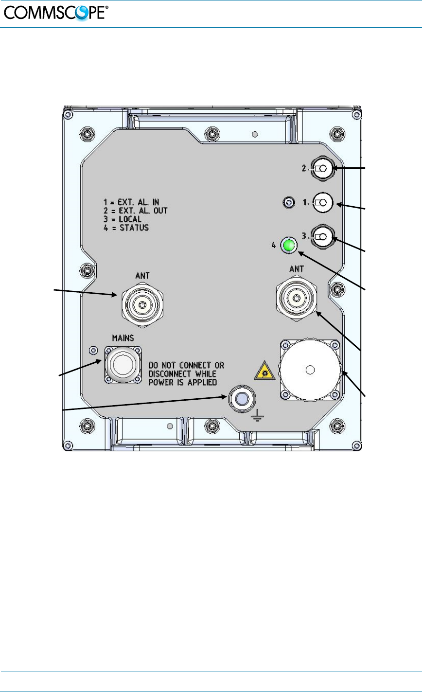
figure 4-10 Connector flange of ION-M7P/85P/17EP/19P, AC version with 2 antenna
ports
AC Mains
connector
Grounding
bolt
Optical-
fiber
connector
Status
LED
A
ntenna
connector
Alarm
input
connector
Alarm
output
connector
not required
for operation
A
ntenna
connector
4. Commissioning
MF0150A2A.doc Manual for ION-
M7P/85P/
17EP
/19P
Page 27
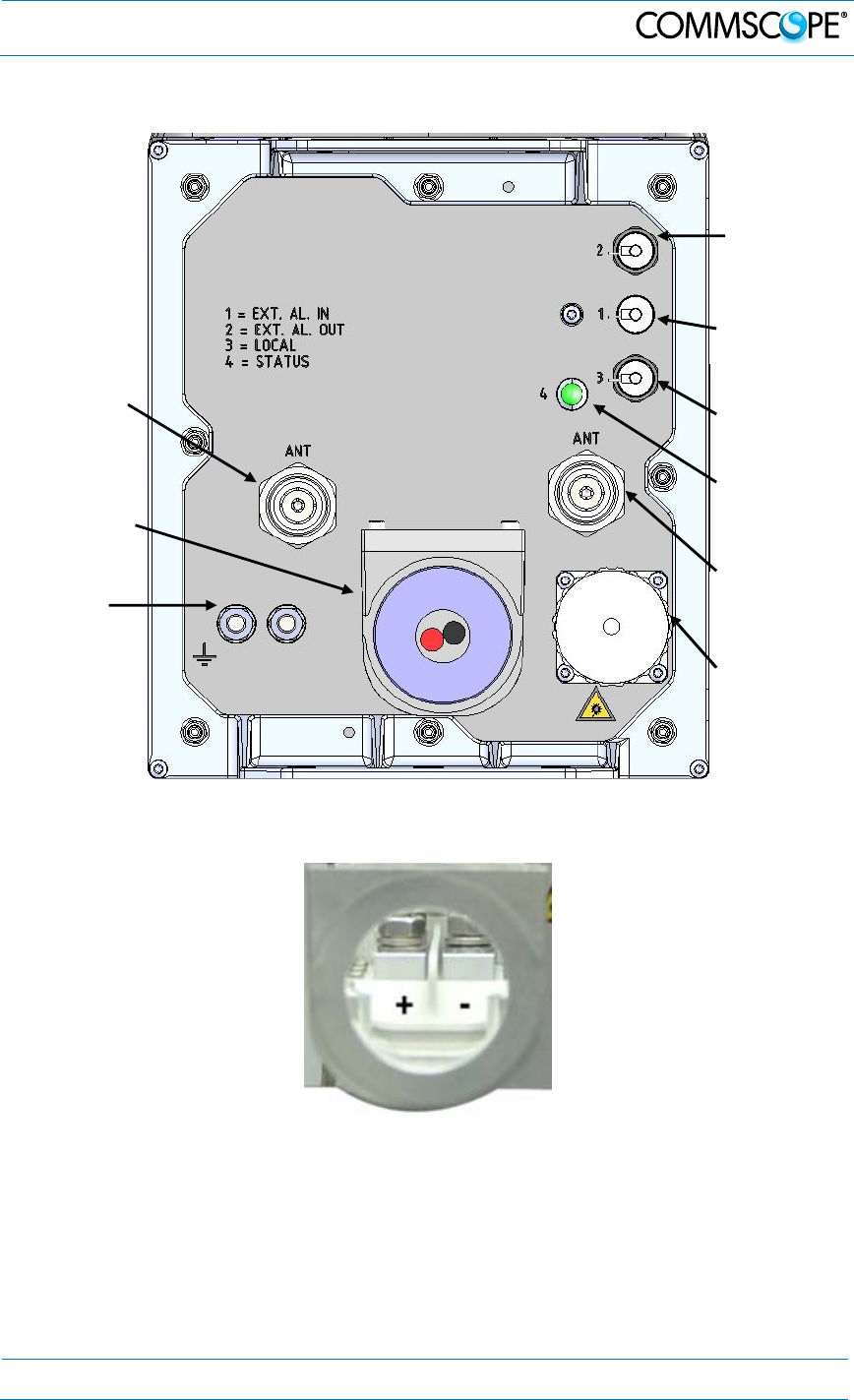
figure 4-11 Connector flange of ION-M7P/85P/17EP/19P, DC version with 2 antenna
ports
figure 4-12 DC Connector of ION-M7P/85P/17EP/19P
DC Mains
connector
Grounding
bolts
Optical-
fiber
connector
Status
LED
A
ntenna
connector
Alarm
input
connector
Alarm
output
connector
not required
for operation
A
ntenna
connector
4. Commissioning
Page 28 MF0150A2A.doc Manual for ION-M7P/85P/17EP/19P
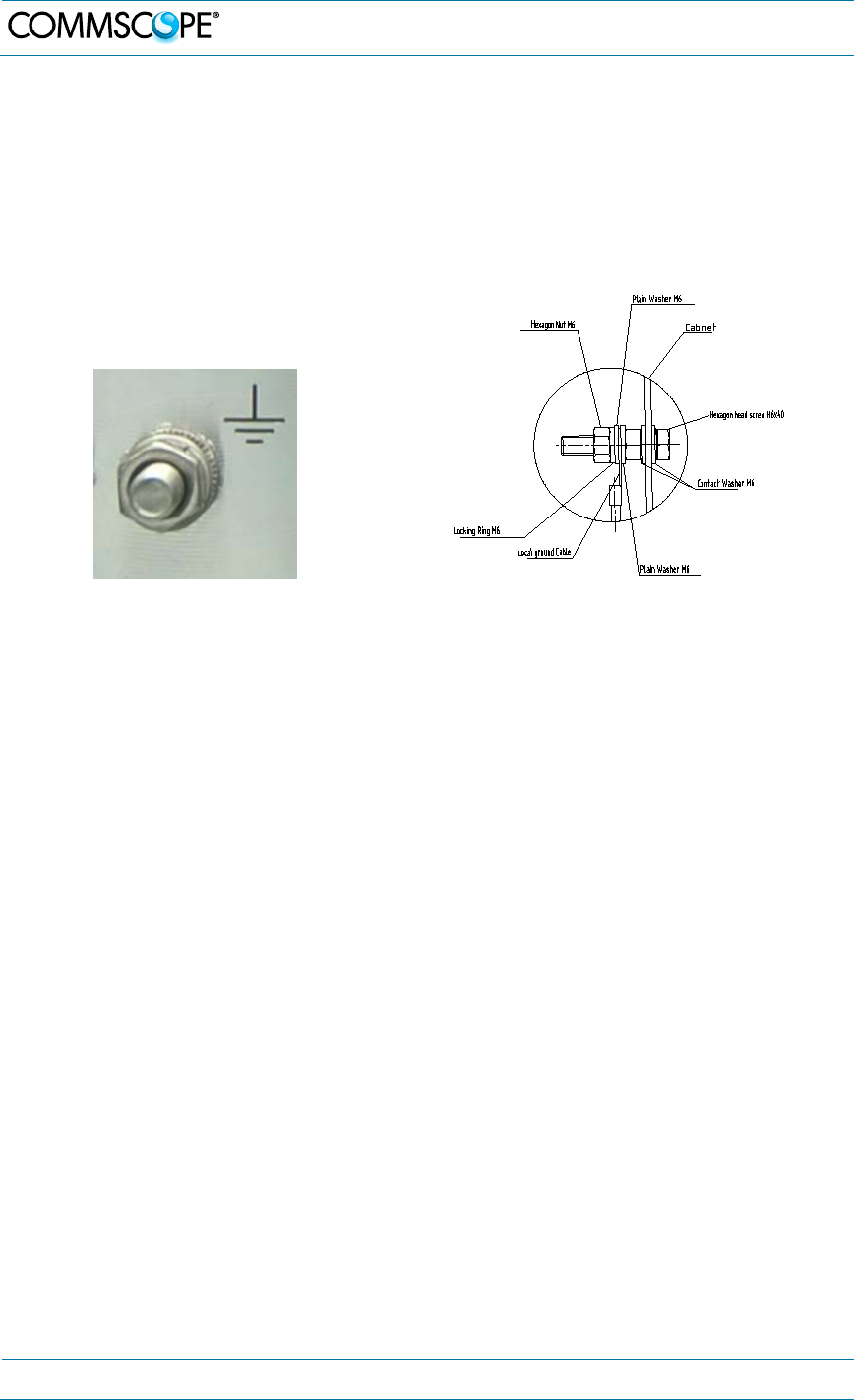
4.2.4. Grounding (Earthing)
The RU must be grounded (earthed).
When double grounding lugs are used (usually in DC applications) they must support
M6 studs with a stud hole spacing of 15.88 mm (5/8”).
1. Connect an earth-bonding cable to one or both of the grounding bolt connections
provided on the connector flange of the Remote Unit. Do not use the grounding
connection to connect external devices.
figure 4-13 Grounding bolt figure 4-14 Grounding bolt, schematic view
2. After loosening the hex nut(s), connect the earth-bonding cable between the two
washers as illustrated in the figures above.
3. Then, fasten all parts again by tightening the hex nut(s).
4. Connect the other end of the ground wire to a suitable permanent ground.
Note: Ground of a second unit (for example RU + EU) has to be connected to the
same equipotential bonding terminal as the Remote Unit. Use bonding cables
of the same length, as short as possible, and with a large wire cross section.
Follow local electrical code practices.
4.2.5. Connection of the Antenna Cables
The Remote Unit has one 4.3-10 type antenna connector labeled “ANT”.
When attaching the antenna cable connector, it is recommended to refer to the
corresponding documentation of the connector manufacturer. The bending radius of
the antenna cable must remain within the given specifications.
The selection of cable and antenna is an important consideration. On the one hand, a
cable with higher loss is less expensive but, on the other hand, it impairs
performance.
Notice: Use an appropriate torque wrench for the coupling torques:
- for 7/16 DIN-type (25 N-m / 19 ft lb) with 1 ¼ in opening,
e. g. item no. 244377 available from the CommScope e-catalog
- for 4.3-10 type connectors (5 N-m, 44 in lb) with 22 mm (7/8) in
opening, e.g. item no. TW-4310
Do NOT use your hands or any other tool (e.g. a pair of pliers). This might
cause damage to the connector and lead to a malfunction of the Remote
Unit.
4. Commissioning
MF0150A2A.doc Manual for ION-
M7P/85P/
17EP
/19P
Page 29
Attention: To minimize passive inter-modulation (PIM) distortion, attention has to be
paid to the physical condition of the connector junctions:
Do not use connectors that show signs of corrosion on the metal surface.
Prevent the ingress of water or dirt into the connector.
Use protective caps for the connectors when not mounted.
Before mounting clean the connectors with dry compressed air.
Before mounting clean the mating surfaces of the connector with a lint-free
alcohol-drenched cloth on a wooden or non-metallic item.
Attach and torque the connectors properly.
Avoid metallic abrasion when mounting the connectors by only screwing the
connecting nut, but not turning the whole connector.
Use a torque wrench to fasten the connector, see above.
Clean the protective caps before mounting for antenna cable replacement.
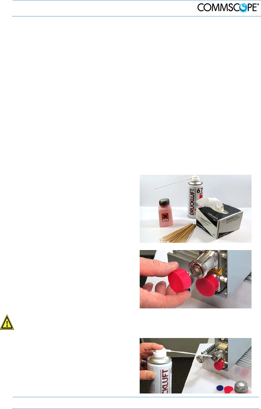
4.2.6. Cleaning Procedure for RF Cable Connectors
The figures in this chapter illustrate the cleaning procedure and do not show the
actual RU.
1. What is needed for the cleaning?
a. Isopropyl alcohol
b. Compressed air
c. Lint-free wipe
d. Cotton buds
2. Remove protective cap from the RF
connector.
Caution: Risk of injury by flying particles when compressed air is used. Wear
protective clothing, especially protective glasses.
3. Remove metal chips and small
particles from the mating and inner
surfaces of the connector using
compressed air.
4. Commissioning
Page 30 MF0150A2A.doc Manual for ION-M7P/85P/17EP/19P
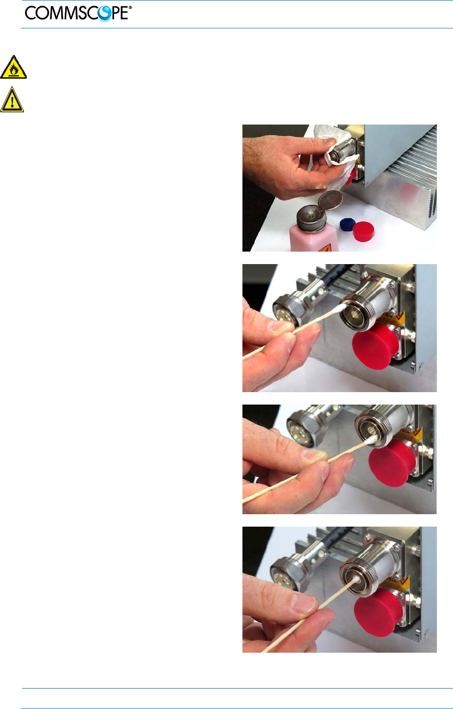
Warning: Flammable material. Risk of fire. Keep away from sources of ignition.
Caution: Eye irritant product. Risk of eye irritation. Avoid contact with eyes and skin.
Wear protective clothing, especially protective glasses.
4. Clean the connector winding with lint-
free wipe drenched with isopropyl
alcohol.
5. Clean the lip of the inner ring with a
cotton bud drenched with isopropyl
alcohol.
6. Clean the inside surface of the inner
ring with a cotton bud drenched with
isopropyl alcohol.
7. Clean the inside of the center
conductor spring tines with a cotton
bud drenched with isopropyl alcohol.
4. Commissioning
MF0150A2A.doc Manual for ION-
M7P/85P/
17EP
/19P
Page 31
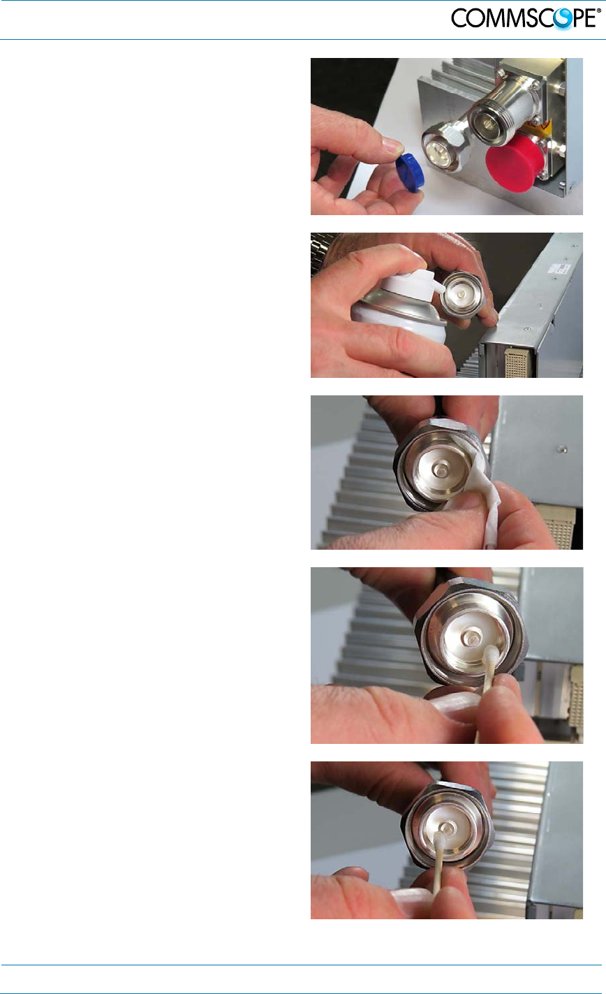
8. Clean in the similar way the
connector of the connected cable.
Remove protective caps from the unit
connector first.
9. Remove metal chips and small
particles from the mating and inner
surfaces of the connector using
compressed air.
10. Continue with the winding area using
lint-free wipe drenched with isopropyl
alcohol.
11. Continue with the inside mating
surface of the inner ring.
12. Clean the outside surface of the
center pin.
4. Commissioning
Page 32 MF0150A2A.doc Manual for ION-M7P/85P/17EP/19P
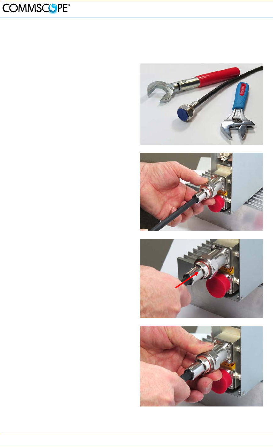
4.2.7. Antenna Cable Connector Assembly
The figures in this chapter illustrate the connection procedure and do not show the
actual RU.
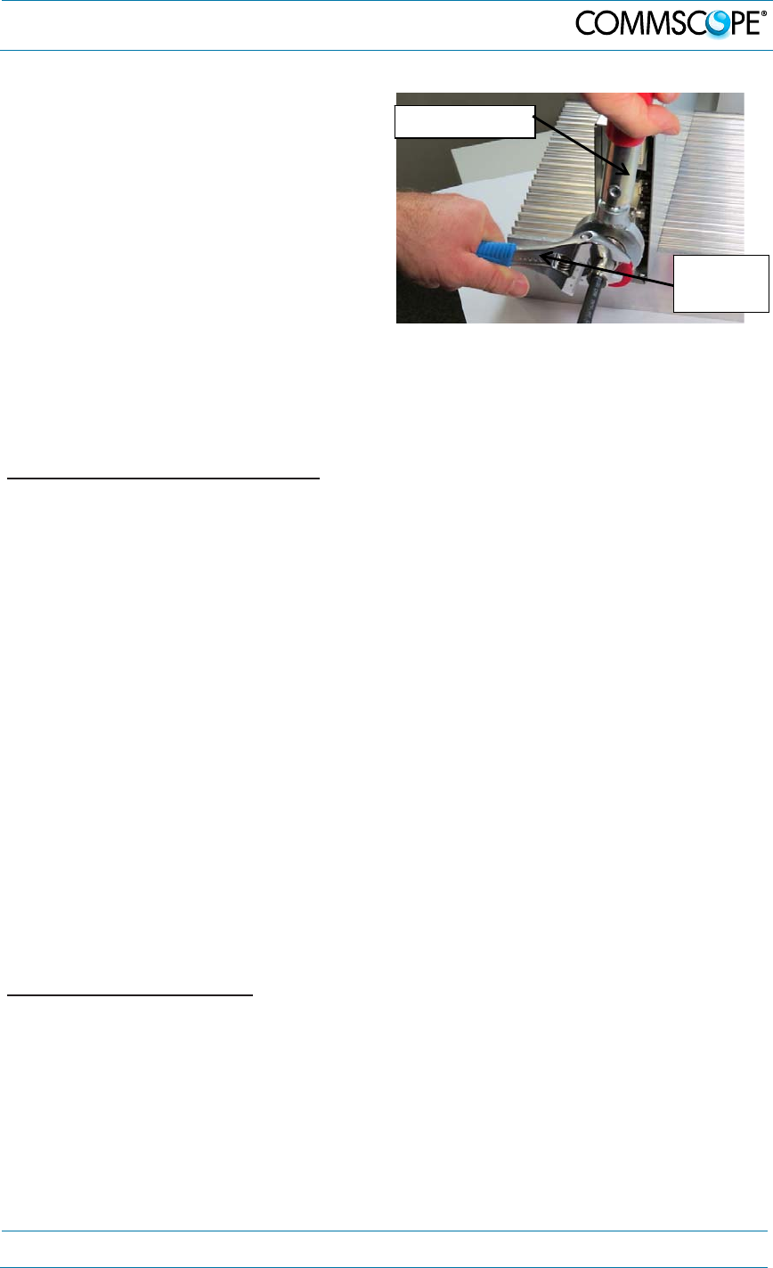
1. What is needed for the connector
assembly?
a. Torque wrench.
b. (Adjustable) counter wrench
2. Join the connectors and turn the
coupling nut until the thread grips.
3. Push in the connector until it clicks.
4. Fasten the coupling nut hand-tight. Do
not turn the connector but the coupling
nut only.
4. Commissioning
MF0150A2A.doc Manual for ION-
M7P/85P/
17EP
/19P
Page 33
5. Retain the cable connector with the
counter wrench and fasten the
coupling nut with the torque wrench
until the torque is applied (torque
wrench clicks).
For angled antenna connectors use your
hand to retain the cable connector and
fasten the coupling nut with the torque
wrench. Make sure only the coupling nut
is turned, not the cable connector.
4.2.8. Optical-Fiber-Cable Connection - Rules
Main optical system parameters:
Fiber:
Single mode fiber, type is E9/125 µm
Attenuation: <0.36 dB / km @ 1310 nm / <0.26 dB / km @ 1550 nm
Dispersion: <3.5 ps / nm km @ 1310 nm / <18.0 ps / nm km @ 1550 nm
Fibre-cable connectors E2000 APC 8°
ION-M system:
The pigtails for the connection between Master Unit and Remote Unit must
have a sufficient length. Protection for the optical fibers must be provided
where the fibers feed into the units.
The system attenuation of the optical fibers, including the connectors, must
not exceed 10 dB.
System attenuation and attenuation of optical components must be determined. This
can be achieved by measuring attenuation with an appropriate measuring instrument.
For pigtails, a total value of <0.4 dB (measured to a reference plug) can be assumed
due to the dead zone of the reflectometer. These measurements must be made with
a sufficient length of optical fiber, at the input and output of the device which has to
be measured.
Fiber-System Installation:
Fiber-cable connectors have to be of the same type (E2000 APC 8°) as the
connectors used for the unit. The fiber-optic cables are connected to the optical
transceiver.
Note: Angled connectors are not compatible with straight optical
connectors; non-compatibility of connectors will result in
permanent damage to both connectors.
Torque wrench
Counter
wrench
4. Commissioning
Page 34 MF0150A2A.doc Manual for ION-M7P/85P/17EP/19P
Before connecting the fiber cables, follow the procedure below to ensure optimized
performance. It is important for these procedures to be carried out with care:
Remove fiber-optic protective caps.
Do not bend the fiber-optic cable in a tight radius (<4 cm) as this may cause
cable damage and interrupt transmission.
Using high-grade alcohol and lint-free cotton cleaning swabs, clean the end of
the fiber-optic cable that will be inserted in the optical connectors on the donor
interface box. Use a fiber end-face inspection tool to scan both, the class fiber
and its surrounding area.
Check for dirt on the cladding, chips/pits, dirt on the ferrule, and scratches.
Connect the fiber-optic cables by inserting the cable end into the laser
receptacle and aligning the key (on the cable end) with the keyed slot.
Do not use any index-matching gels or fluids of any kind in these connectors.
Gels are intended for laboratory use and attract dirt in the field.
Note: Care should be taken when connecting and disconnecting fiber-
optic cables - use the connector housing to plug or unplug a fiber.
Scratches and dust significantly affect system performance and
may permanently damage the connector. Always use protective
caps on fiber-optic connectors not in use.
Cleaning Procedure for Fiber-Optical Components:
Caution: Laser radiation. Risk of eye injury in operation. Do not stare into the
beam; do not view it directly or with optical instruments.
Any impurity in the fiber connection results in additional optical transmission loss
which could cause whole system failure. It is thus recommended that every fiber
connector be inspected and cleaned prior to mating.
When you clean fiber components, always complete the following steps carefully:
1. Turn off the ION system (laser sources) before you inspect fiber connectors.
2. Check the connectors or adapters with a fiberscope before cleaning.
3. If the connector is dirty, clean it with a lint-free wipe (dry cleaning).
4. Inspect the connector.
5. If the connector is still dirty, repeat the dry cleaning technique.
6. Inspect the connector.
7. If the connector is still dirty, clean it with 99% isopropyl alcohol (wet cleaning)
followed immediately with a dry clean in order to ensure no residue is left on
the end face.
8. Repeat steps 5 through 7 until end face is clean.
Note: For a more detailed description, please refer to:
http://www.cisco.com/en/US/tech/tk482/tk876/technologies_white_paper09186
a0080254eba.shtml
4. Commissioning
MF0150A2A.doc Manual for ION-
M7P/85P/
17EP
/19P
Page 35
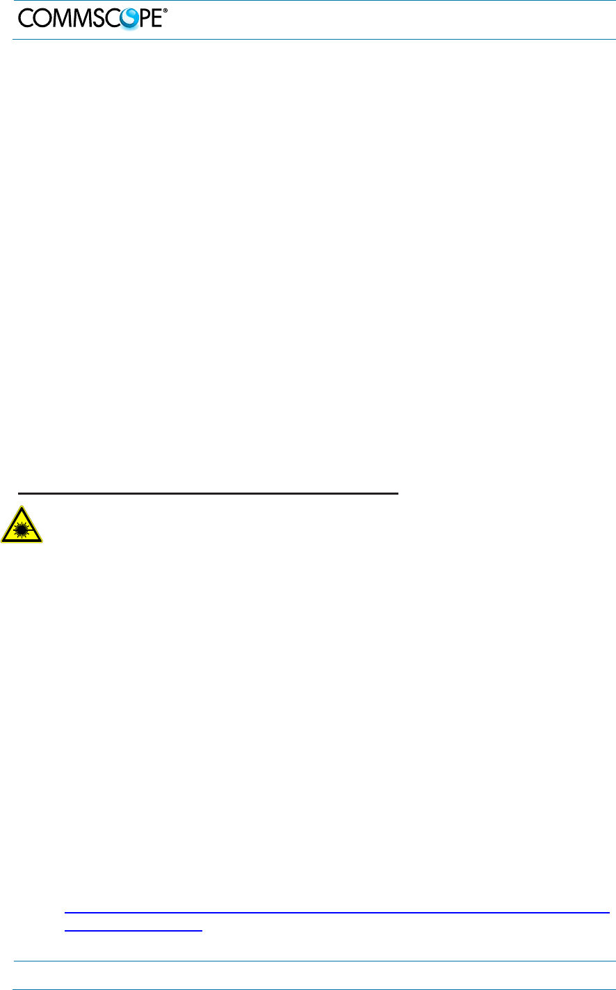
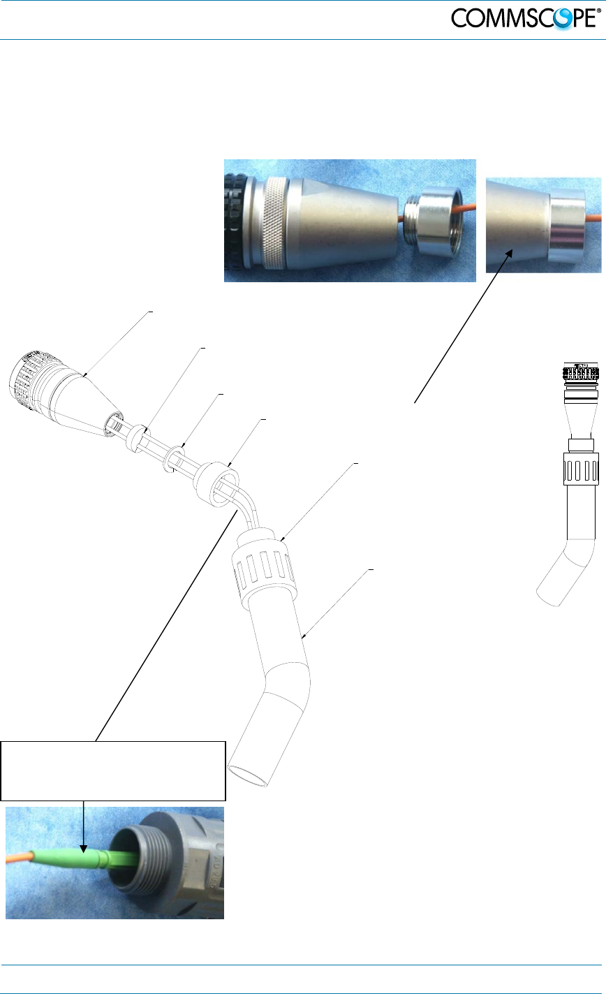
4.2.9. Protective Plug
A protective plug is provided for the connection of the fibre-optic cables.
figure 4-15 Protective-plug assembly
Note: Only high-quality connectors must be used for this type of plug.
Qualified brands are Diamond or Huber & Suhner.
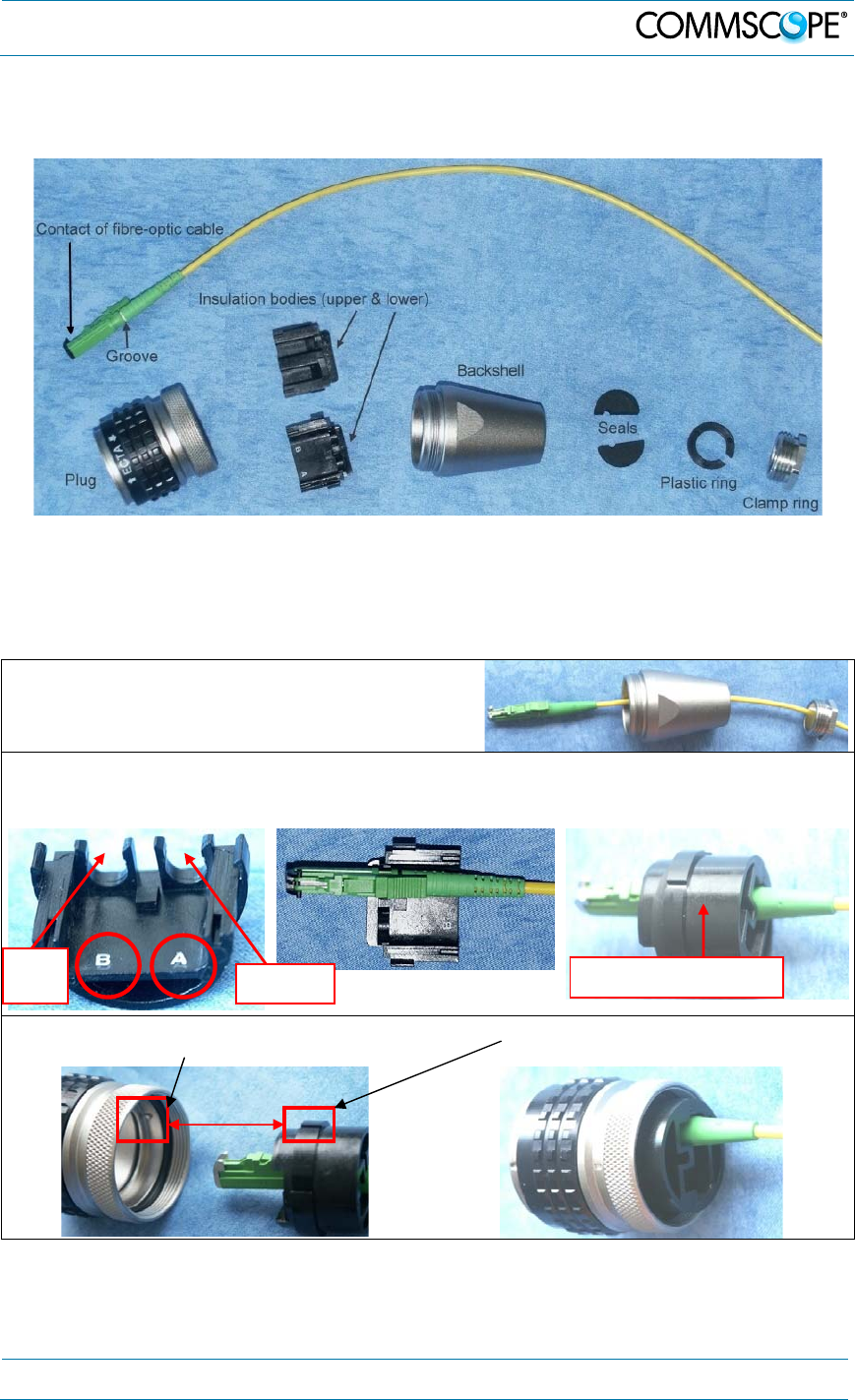
For plug assembly, observe the following instruction:
1. Pass one or two contacts through the
backshell and the clamp ring.
2. Place the contact(s) on the lower insulation body by pushing the groove of the
contact into the cavity. If there is only one contact, cavity A must be used. *
3. Then, mount the upper insulation body on the lower insulation body. **
4. Bring the insulator into the plug. The narrow groove of the insulator must be fitted
into the stamp of the plug.
* To release the contact for disassembling, push the inner snap to the side and pull the contact out.
** To release upper and lower insulation bodies for disassembling, use a small screwdriver and
carefully open the snap-connections at the left and the right side of the insulator without
damaging them.
Upper insulation body
Cavity A
Cavity
B
4. Commissioning
Page 36 MF0150A2A.doc Manual for ION-M7P/85P/17EP/19P
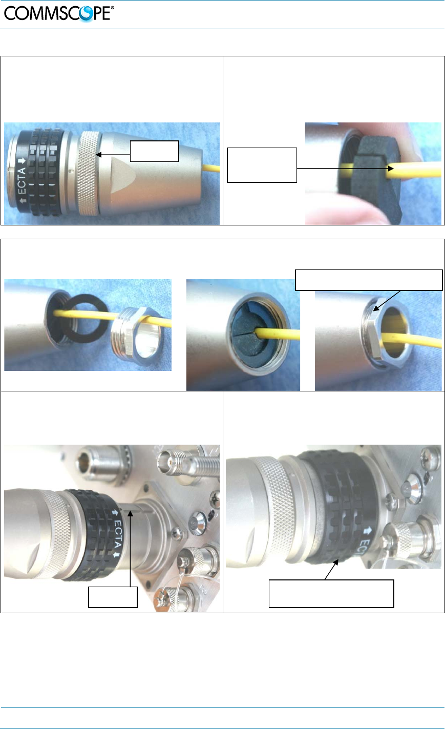
5. Fasten the insulator by screwing the
backshell tight onto it. Use a spanner
with opening 32 to screw the
backshell tight (no gap).
6. Place the appropriate seal parts (with
one groove for one contact or two
grooves for two contacts) over the
cable(s) and push them into the
backshell.
7. Bring the plastic ring over the cable(s), push it into the backshell and compress
the seals and plastic ring by screwing the clamp ring tight (no gap) using a
spanner with opening 20. ***
8. Connect the plug to the optical-fibre
connector of the Remote Unit, again
by fitting a stamp on the plug into the
groove of the connector.
9. To lock the connector, push the black
locking ring forward.****
*** For disassembling, release the clamping ring and remove the seals and the plastic ring first.
**** Locking mechanism: The system of locking the plug is based on a “push-pull” mechanism. The
locking ring has to be pushed forward to lock the connector and pulled back to free the
connection.
Seals with
one groove
Groove Push forward to lock, pull
bac
k
to
fr
ee
co
nn
ect
i
o
n
No gap
Screw tight until gap is closed
4. Commissioning
MF0150A2A.doc Manual for ION-
M7P/85P/
17EP
/19P
Page 37
4.2.10. Protective-Tube Kit
As additional protection for the optical fibres, this connector type can be
supplemented by a special tube kit. To fasten the tube correctly, first unscrew the
clamp ring (if already installed) of the original plug kit. Then, proceed according to the
following instruction:
Screw the reducer to
the protective plug
backshell without any
gap!
Place the appropriate seal
parts (with) one groove for
one contact or two grooves
for two contacts) over the
cable(s) and push them into
the backshell! Protective tube
Reducer
Coupling
Protective plug
Fiber cable
Ring 3/4
G1055M0
figure 4-16 Tube-kit installation
Push the fiber-optic cable carefully
through the tube until it comes out
at the other end.
4. Commissioning
Page 38 MF0150A2A.doc Manual for ION-M7P/85P/17EP/19P
4.2.11. Mains Power Connection
Before connecting electrical power to the unit, the system must be grounded as
described in chapter 4.2.4.
Mains power must be connected at the mains connector of the unit.
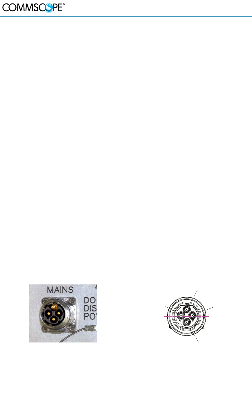
4.2.11.1. Mains power connection AC
1. Take the Mains power cable that was delivered with the RU.
2. Locate or install a suitable power junction box or receptacle near the RU and
route the power cable from the power source to the RU. Do not connect the
cable to the RU’s Mains connector at this time. The power source must be
interruptible.
3. The Mains cable must be properly secured observing local regulations and
electrical codes. Be sure to allow enough slack in the cable at the RU to plug
or unplug the cable into the Mains connector of the RU.
4. Wire the power cable to the junction box or receptacle. Refer to the color code
and pin numbers shown in figure 4-18 (AC cable), and table 4-2.
5. With the cable’s Mains plug disconnected from the RU, turn the circuit breaker
on, unscrew the plug’s protective cover, and carefully test the plug with a
voltmeter to ensure that the voltage and polarity are correct.
6. Once the testing has been completed, turn off the circuit breaker.
7. Unscrew the protective cover from the Mains connector of the RU (figure
4-17).
8. Insert the plug into the Mains connector and tighten the clamping ring until it is
hand tight. Do not over-tighten the clamping ring.
P
i
n
PE
P
in1
Pin2
Pin
3
figure 4-17 Mains power connector figure 4-18 Mains power cable - AC
4. Commissioning
MF0150A2A.doc Manual for ION-
M7P/85P/
17EP
/19P
Page 39
The Mains cable is part of the delivery. It’s available in two wiring configurations:
Pr ot ect ive Cap
Wiring 1
Pin Name Color
1 Phase Black
2 Neutral White
3 n.c. n.c
PE Ground Green
Wiring 2
Pin Name Color
1 Phase Brown
2 Neutral Blue
3 n.c. n.c
PE Ground Green/Yellow
table 4-2 AC power cable pinning
For the AC power supply connection, a minimum cross section of 1.5
mm2 is required. Each wire must observe the applicable national
regulations regarding loop impedance, voltage drop, and methods of
installation. Make sure to connect the correct voltage to the unit.
Note: Do not connect or disconnect the power cord at the mains connector while
power is on. Turn off mains* power before connecting the power cord at
the Remote Unit, then, engage mains again.
* Mains power must be interrupted with an external mains breaker. For the mains breaker, observe
the following recommendation:
120 Volt / 20 Amp max. or 240 Volt / 16 Amp, single-phase, 50 / 60 Hz AC service is needed, i.e. the
external AC breaker should be 20 Amps max. for 120-Volt service or 13 - 16 Amps for 240-Volt
service.
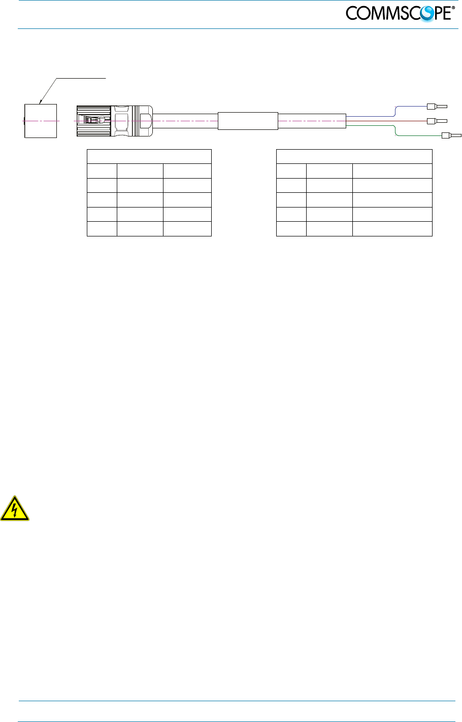
4.2.11.2. Mains power connection DC
Caution: Danger of electrical hazard by high current. Disconnect mains
power before opening the DC connector housing.
Note: The Mains cable must be properly secured observing local regulations and
electrical codes. Be sure to allow enough slack in the cable at the RU to mount or
dismount the cable into the DC Mains connector of the RU.
4. Commissioning
Page 40 MF0150A2A.doc Manual for ION-M7P/85P/17EP/19P
Unscrew the two M3 x 12 captive screws
and take off the cover from the DC Mains
connector housing. At the RU housing
the cover is inserted into a recess, so first
lift the cover at the front and carefully pull
it out from the recess.
Then remove the rubber plug.
Double lug DC cable connectors need to
be M6 with a stud hold spacing of 15.88
mm (5/8”).
Rubber
plug
4. Commissioning
MF0150A2A.doc Manual for ION-
M7P/85P/
17EP
/19P
Page 41
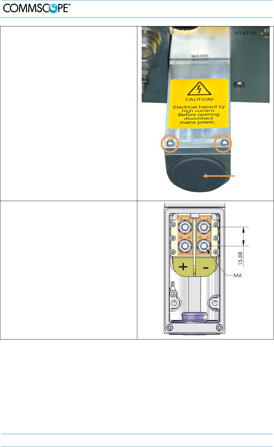
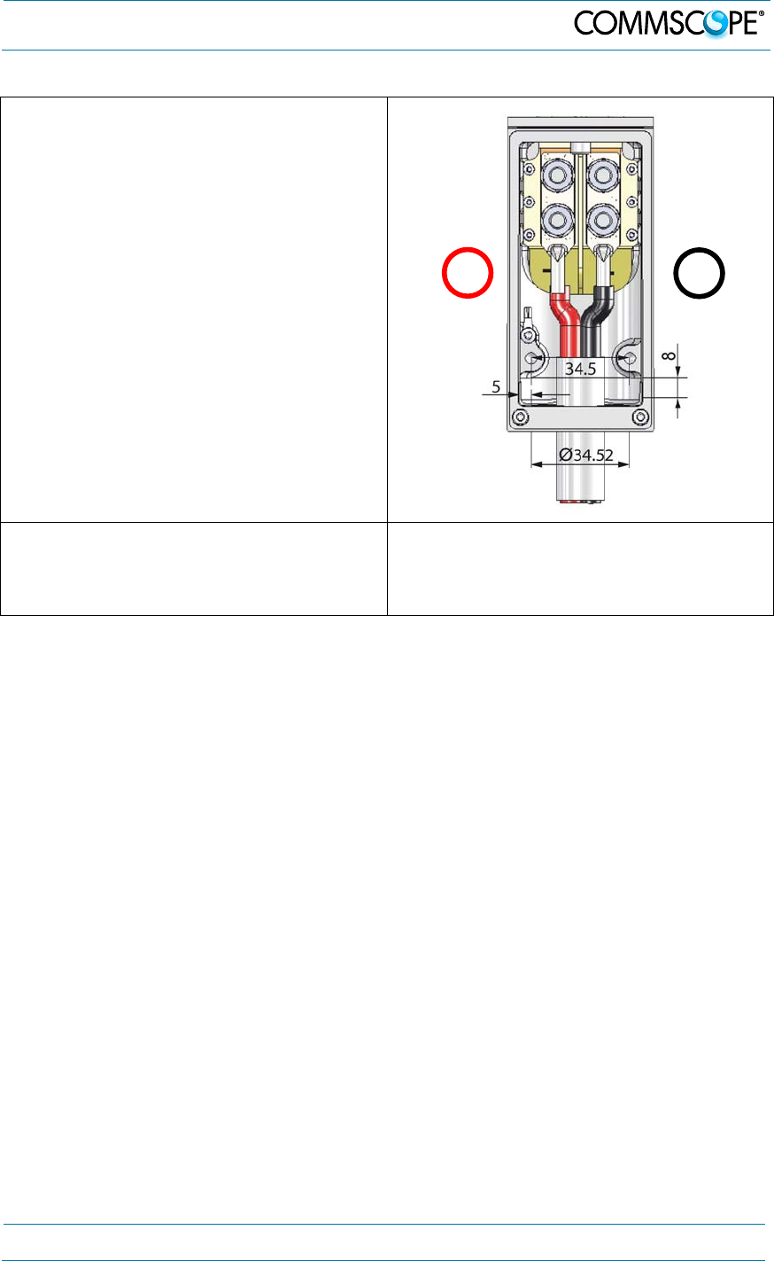
First, install a conduit fitting (not
contained in scope of delivery) to the
34.52 mm hole. This must be a suitable
fitting for a 1 Inch conduit with lock nut.
Inside, the clearance around the hole is
5 mm, the maximum space for the nut is
8 mm. Then, insert your wiring through
the opening and mount it to the M6 mains
terminals. Observe the correct polarity.
Close the conduit fitting to ensure water
tightness. For strain release, two M5
threaded holes are provided; the distance
between the threaded holes is 34.5 mm.
Mount the housing cover by inserting it
into the recess at the repeater cabinet
and fastening the two M3 x 12 captive
screws.
Attention: For the DC power supply connection, a minimum cross section of
6.6 mm2 (≤ AWG 9) per potential is required. Each wire must
observe the applicable national regulations regarding loop
impedance, voltage drop, and methods of installation. Make sure
to connect the correct voltage to the unit. To ensure water-
tightness of the unit, use the correct size of cable gland.
Note: Do not connect or disconnect the power cord at the mains connector while
power is on. Turn off mains* power before connecting the power cord at
the Remote Unit, then, engage mains again.
* Mains power must be interruptible with an external mains breaker (40 A). For the mains breaker,
observe the local regulations of the DC provider.
+-

4. Commissioning
Page 42 MF0150A2A.doc Manual for ION-M7P/85P/17EP/19P
4.2.12. External Alarm Inputs and Outputs
There are four alarm inputs and four alarm outputs. Each alarm output can be
assigned individually to any alarm at the Remote Unit. Settings need to be made via
the ION-M Master Controller. For details please refer to the corresponding chapter in
the User’s Manual of the ION-M Master Controller.
Note: The manufacturer / supplier of this system assumes no liability for
damage caused by equipment connected to external outputs or by
effects from such equipment.
As accessory equipment the alarm kit is available to connect external devices to the
external alarm inputs and outputs. For the exact ID No., please refer to section 7.3
4. Commissioning
MF0150A2A.doc Manual for ION-
M7P/85P/
17EP
/19P
Page 43
Spare Parts. Subminiature circular connectors series 712 with five and seven
contacts, which are contained in the alarm kit, can be ordered directly from the
Binder Connector Group, the manufacturer, or indirectly from CommScope.
For the location of the external-alarm inputs and outputs see figure “Connector
Flange”.
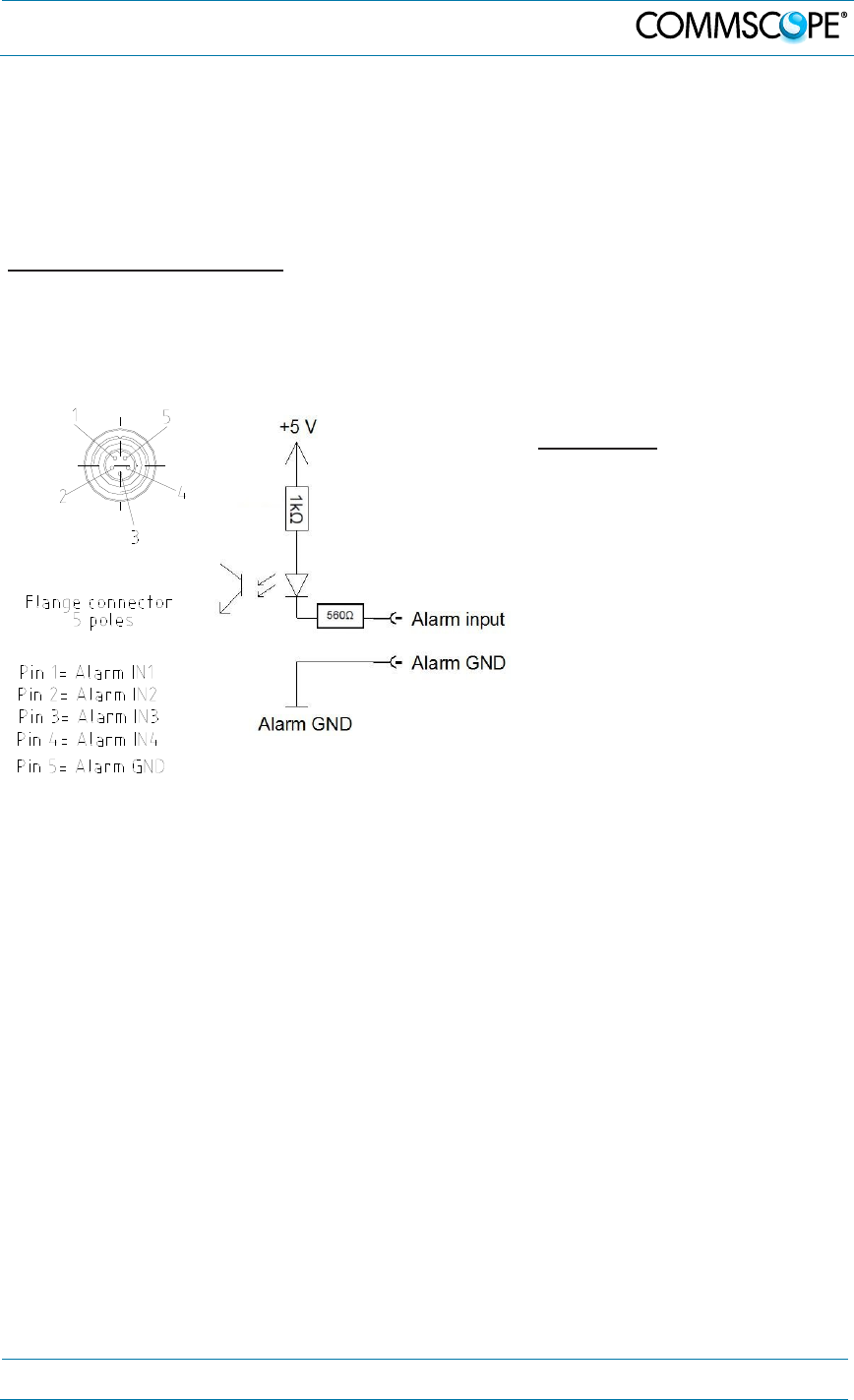
Optocoupler-Alarm Inputs
With the external alarm inputs it is possible to monitor the status of connected
devices, e.g. a UPS, via software. All alarm inputs are normally high (5 V) without
connection. The polarity (high/ low) can be set via the software at the Master Unit (for
details please see corresponding software manual).
Alarm Inputs:
(decoupled via optocoupler)
Input control/alarm signal/switch
contact dimensioning:
UMAX = 5 VDC
(from Alarm Card input out)
IMAX = 5 mA
(from Alarm Card input out)
R(ON)MAX = 1kΩ
(of the external switch)
│φGND- φIN GND│≤ 60 V
figure 4-19 Flange
connector, 5 poles figure 4-20 Alarm inputs (optocoupler)
4. Commissioning
Page 44 MF0150A2A.doc Manual for ION-M7P/85P/17EP/19P
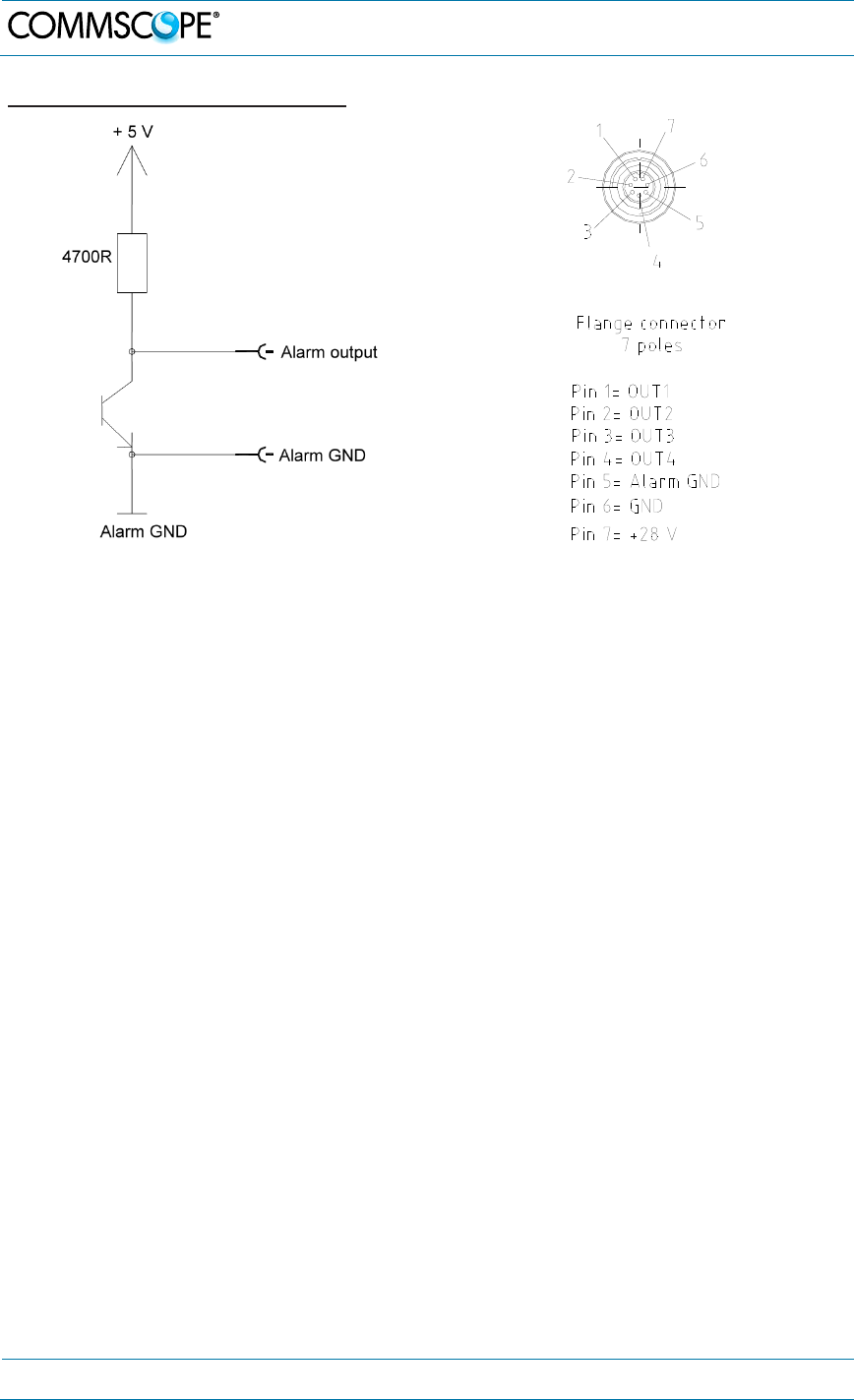
Alarm Outputs and +28V Output
figure 4-21 Alarm outputs (optocoupler) figure 4-22 Flange connector, 7 poles
The alarm outputs (pins 1 to 4: open collector output 5 V / 1 mA; see figure 4-22) are
normally low. In case of an alarm they are high active (5 V). They can be used to
monitor alarms with an external alarm indicator.
The +28 V pin (pin 6&7) is specified to 28 VDC / 1 A and is protected by a
thermoswitch. In case of exceeding this current between pin 7 and GND, the
thermoswitch turns into a high-resistive status. In this case no fuse needs to be
replaced. Just wait a few minutes until the thermoswitch reaches the normal
operating temperature again.
Note: The manufacturer / supplier of this system assumes no liability for
damage caused by equipment connected to external outputs or by
effects from such equipment.
4. Commissioning
MF0150A2A.doc Manual for ION-
M7P/85P/
17EP
/19P
Page 45
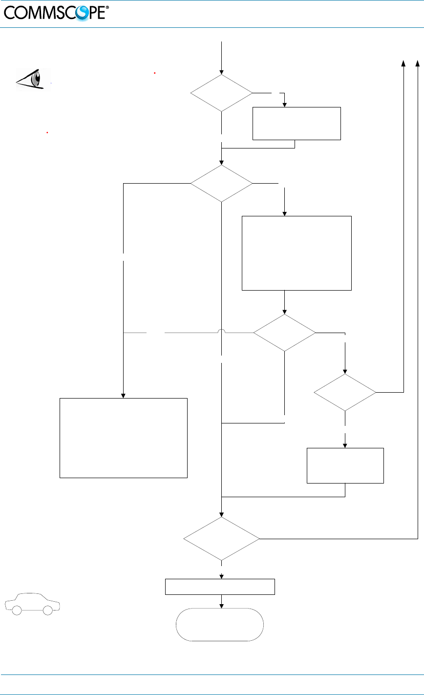
4.2.13. Commisioning Flowchart
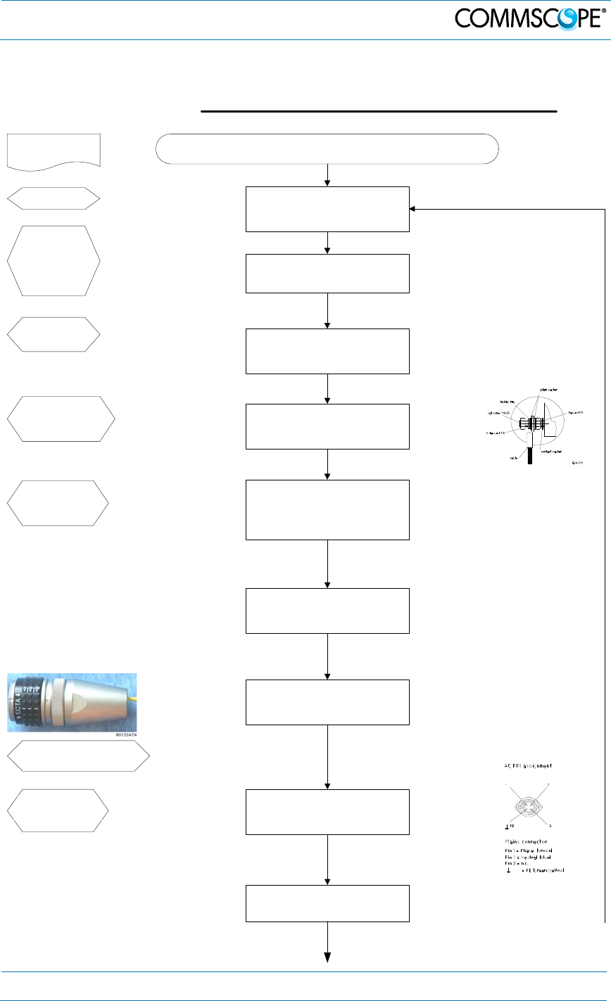
Commissioning an ION-M Remote Unit
Start
Mechanical installation
Fasten wall or pole mounting kit to wall or
pole.
Manual for Remote
Unit
Electrical connections
Connect grounding cable and
ground the RU.
Mains
Switch mains power on.
Philips
screwdriver
Screw driver
Spanner, size
13 mm
Electrical connections
Connect AC power to the power cable.
Ensure there is a circuit breaker between
mains and RU.
RF connection
Connect antenna cable to antenna port.
Optical connections
Mount the optical fibre with E2000 APC8°
connector into the connector. Plug the
connector into the RU.
Mechanical installation
Mount RU to mounting kit, ensure suffient
air flow and avoid thermal short circuits.
Preperation
Unpack RU, RU accessories and
mounting kit.
External devices
Connect external devices to the external
in or alarm out connectors, or to the
connecting board inside the RU.
G1055Z0
Mounting kit
Spanner, size
13 mm
Drilling
machine
Dowels
Screw driver
Grounding cable
Spanner 13 mm
Mains cable
Connecting kit
Alarm kit
(M-cabinet)
E2000 APC8° connector
Spanner with opening 32
4. Commissioning
Page 46 MF0150A2A.doc Manual for ION-M7P/85P/17EP/19P
Output:
All RUs okay.
Go to MU
External error
Close the door (RUs with a door).
Check externally connected devices.
Check fibre loss of optical link.
Check optical connectors.
Clean optical connectors.
Check optical output power of corresponding
OTRx at master unit.
ALC alarm: Decrease DL input power of
affected band.
VSWR alarm: Check antenna and cable.
LED status
Proceed to MU to set up the SW
Orange
Yes
Internal Error
Change power supply (RUs with a
door).
Reduce environmental temperature.
Eliminate thermal short circuit.
Disconnect and connect mains. Fans
should run. If not, replace the fans at
RU.
MU: Change amplifier setting at MU
controller
Red
LED statusYellow
Green
Red
Finished setting up
all RUs?
Green
Spare RU
available?
Yes
Contact customer
service
No
Yes
LED on?
Check power switch inside RU
(RUs with door).
Check mains cabling.
Check mains power.
No
No
5. Alarms and Troubleshooting
MF0150A2A.doc Manual for ION-
M7P/85P/
17EP
/19P
Page 47
5. Alarms and Troubleshooting
All alarms occurring can be checked via software at the Master Unit to where a
message is transmitted when the software acknowledges a valid alarm. A new alarm
message will not be repeated if the reason for the alarm is cleared or if the alarm
continues.
A new alarm message will be generated if the alarm is interrupted for at least five
seconds after acknowledgement. Refer to the corresponding software documentation
of the Master Unit for details.
For local supervision, a status LED on the connector flange of the unit (position see
section 4.2.3) gives an indication of possible reasons for alarms. This table shows
possible on-site measures that could be checked before referring to the Master Unit
alarm list.
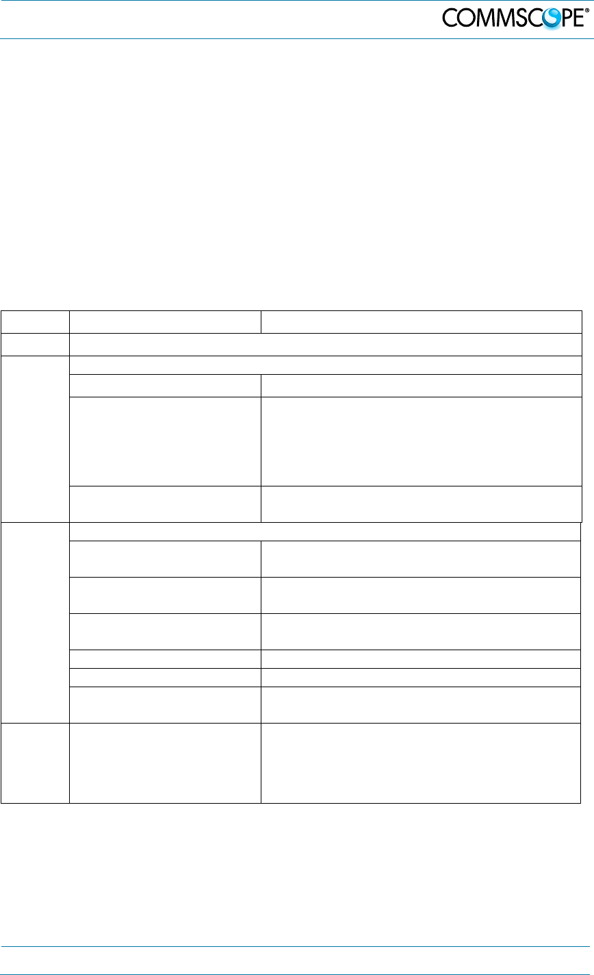
LED Alarms Possible on-site measures
Green No alarm Status ok
Orange
Alarms not directly related to RU/EU:
External alarms (RU only) Check externally connected devices.
Optical alarm Rx
(RU only)
Check fibre loss of optical link.
Check optical connectors.
Clean optical connectors.
(MU: Check optical output power of
corresponding OTRx at Master Unit).
ALC alarm (MU: Decrease DL input power of affected
band).
Red
Alarms directly related to RU/EU:
Power 28 V Change power supply (RUs with door).
Replace the affected Remote Unit.
Temperature Reduce environmental temperature.
Eliminate thermal short circuit.
Fan (RUs/EUs with fan) Disconnect and connect mains. Fans should
run. If not, replace the fans at RU.
I²C Disconnect and connect mains.
Optical alarm Tx Exchange RU/EU.
Amplifier “Power Down” (MU: Change amplifier setting at MU
controller).
Status
LED off Mains
Check power switch inside of RU/EU
(RUs/EUs with door).
Check mains cabling.
Check mains power.
table 5-1 Status LED alarms
The status of the RU/EU can be checked via the Master Unit (for details please refer
to the software manual of the Master Controller).Explicit troubleshooting is also
available in the MU software (software manual or WEB Interface).
The connection of the external alarms inputs and outputs provided is described in
chapter 4.2.12.

6. Maintenance
Page 48 MF0150A2A.doc Manual for ION-M7P/85P/17EP/19P
6. Maintenance
6.1. General
Read and observe chapter 1.2 Health and Safety.
Caution: Rotating fans. Risk of injury in operation. Wear tight-fitting clothes and
disconnect mains before connecting or replacing or cleaning the fan unit.
Caution: The unit reaches high temperature in operation. Risk of burns by hot
surface. Do not touch the unit before it has sufficiently cooled down.
Note: The Remote Unit does not require preventative maintenance measures.
Note: We recommend checking the cleanliness of the unit and in particular of
the heat sink / fan(s) at appropriate intervals depending on the degree of
dust and dirt at the installation site. If necessary, any dusty or dirty areas /
parts should be cleaned at regular intervals, which also depend on the
degree of dust and dirt at the installation site.
Maintenance of the ION-M RUs should be performed by replacing only components
that are described in this chapter. In order to maintain the warranty, avoid
unintentional damage to the seals on the modules.
Note: When sending back the unit, use appropriate packaging. Use of the
original packaging for shipping the unit is strongly recommended.
Note: Defective parts should only be replaced by original parts from the
supplier. All service work performed inside the housing is performed at
the users own risk.
Note: Ensure the Remote Unit has been disconnected from mains power
during maintenance.
Note: Label any unlabelled cables before disconnecting them to ensure
correct reconnection.
Unless otherwise agreed to in writing by CommScope, CommScope’s general limited
product warranty (http://www.commscope.com/Resources/Warranties/) shall be the
warranty governing the Remote Units, including the installation, maintenance, usage
and operation of the Remote Units.
For most maintenance procedures, appropriate tools are required to ensure correct
handling. All of these tools can be ordered from the supplier.
Note: All Remote Unit screws have a right-hand thread, and are tightened by
turning the screws clockwise and loosened by turning them counter-
clockwise with an appropriate tool.
Due to the design of the Remote Unit, the fan unit is the only component that should
be replaced in the field. Please contact the supplier for replacement of any other
components.
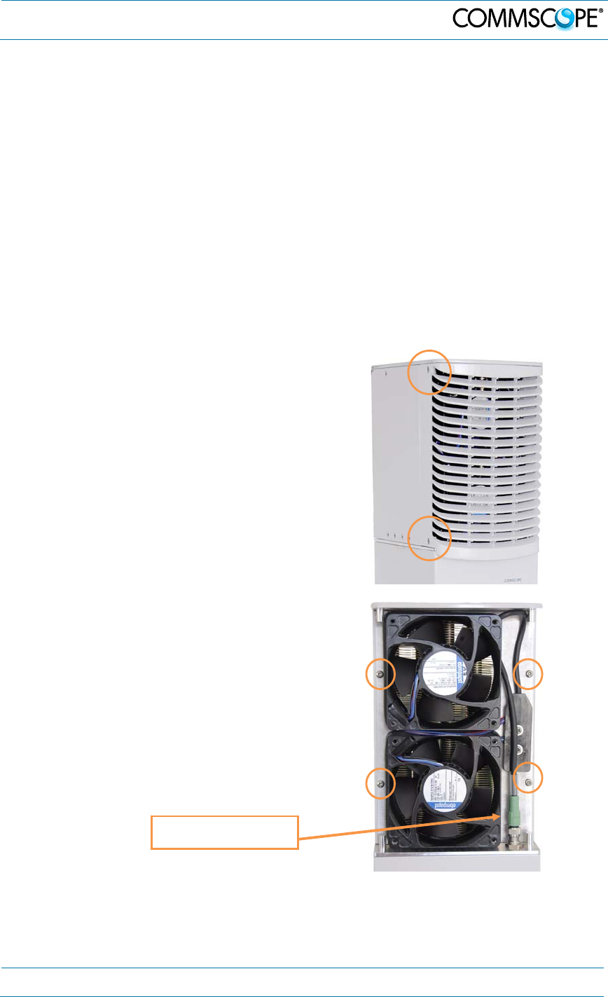
6. Maintenance
MF0150A2A.doc Manual for ION-
M7P/85P/
17EP
/19P
Page 49
6.2. Replacing the Fan Unit
Replacement of the fan unit is not required as a preventative measure. Only if an
alarm indicates a malfunctioning of a fan must the unit be exchanged.
Note: Please observe that the fan unit can only be replaced as a whole. Do
not remove the fans separately.
Note: NEVER blow out the fan unit with compressed air. This would cause
permanent damage to the unit.
Read and observe chapter 1.2 Health and Safety as well as the instructions in
section 6.1 General before starting with the replacement.
1. Switch off the Remote Unit. Make sure that mains power is disconnected for the
following replacement procedure. Then, proceed as follows:
2. Unscrew the four Pan-head screws
(two at each side of the cabinet) and
remove the fan cover.
3. Unscrew and disconnect the fan
connector and unscrew the four Pan-
head screws the fan plate is fastened
to the cabinet. Take out the fan unit,
replace it by the new one, fasten the
four Pan-head screws for the fan unit,
re-connect the fan connector and
mount the cover to the cabinet.
Fan connector
6. Maintenance
Page 50 MF0150A2A.doc Manual for ION-M7P/85P/17EP/19P
6.3. Cleaning the Heat Sink
To avoid a malfunctioning of the Remote Unit, the heat sink should be cleaned in
case of pollution. In order to prevent any damage, proceed as explained in the
following.
Note: Read and observe chapter 1.2 Health and Safety as well as the
instructions in section 6.1 General before starting with the replacement
procedure. Then, proceed as follows:
1. Switch off the Remote Unit. For the following procedure ensure that mains power
is disconnected and that the fans have stopped rotating.
2. Before any cleaning action, remove the fan cover and the fan unit from the
Remote Unit as described in the previous section 6.2 Replacing the Fan Unit.
Caution: Risk of injury by flying particles when compressed air is used. Wear
protective clothing, especially protective glasses.
3. Use compressed air (max. 5 bars) to blow out any dust, dirt, or other debris in the
heat sink from back to front.
4. In case the dirt cannot be blown out completely from the heat sink and parts of it,
still stick to the ribs, clean the parts concerned carefully from the front with the
soft brush. Take care that the material is not scratched or damaged.
5. After cleaning the heat sink, mount the fan unit and the fan cover again according
to section 6.2 Replacing the Fan Unit. Then, reconnect mains power and power
up the unit.
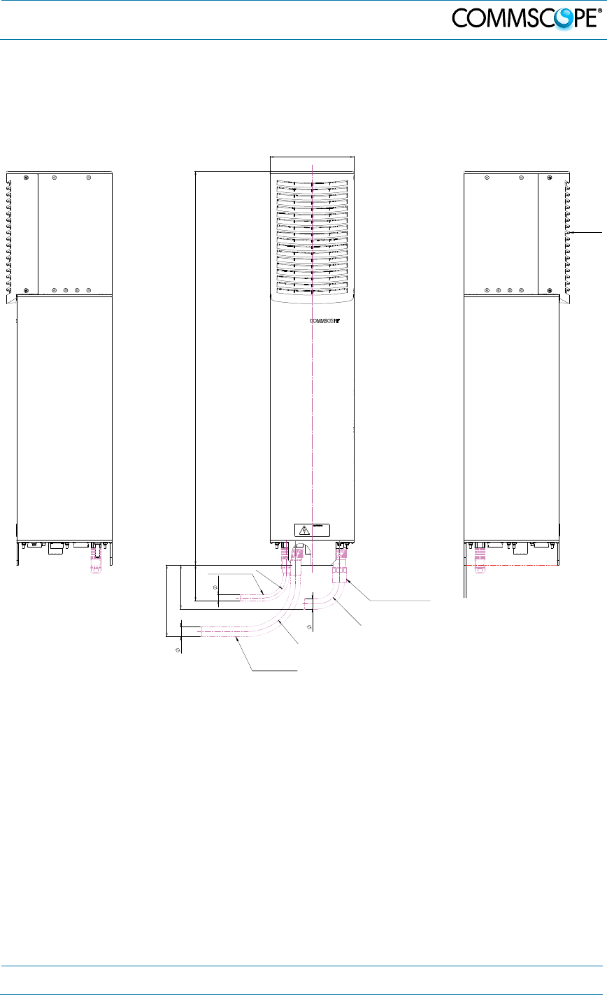
7. Appendix
MF0150A2A.doc Manual for ION-
M7P/85P/
17EP
/19P
Page 51
7. Appendix
7.1. Illustrations
R
45m
in.
12 . 5
75
R
1
00m
in.
15 0
21
Air f l o
w
Power IN Cabl e
Ex t e ns i o n Uni t
Cabl e br idge t o
Prot ect ive Tube Kit
17 6
R
824
45m
in.
21
92
figure 7-1 Cabinet drawing
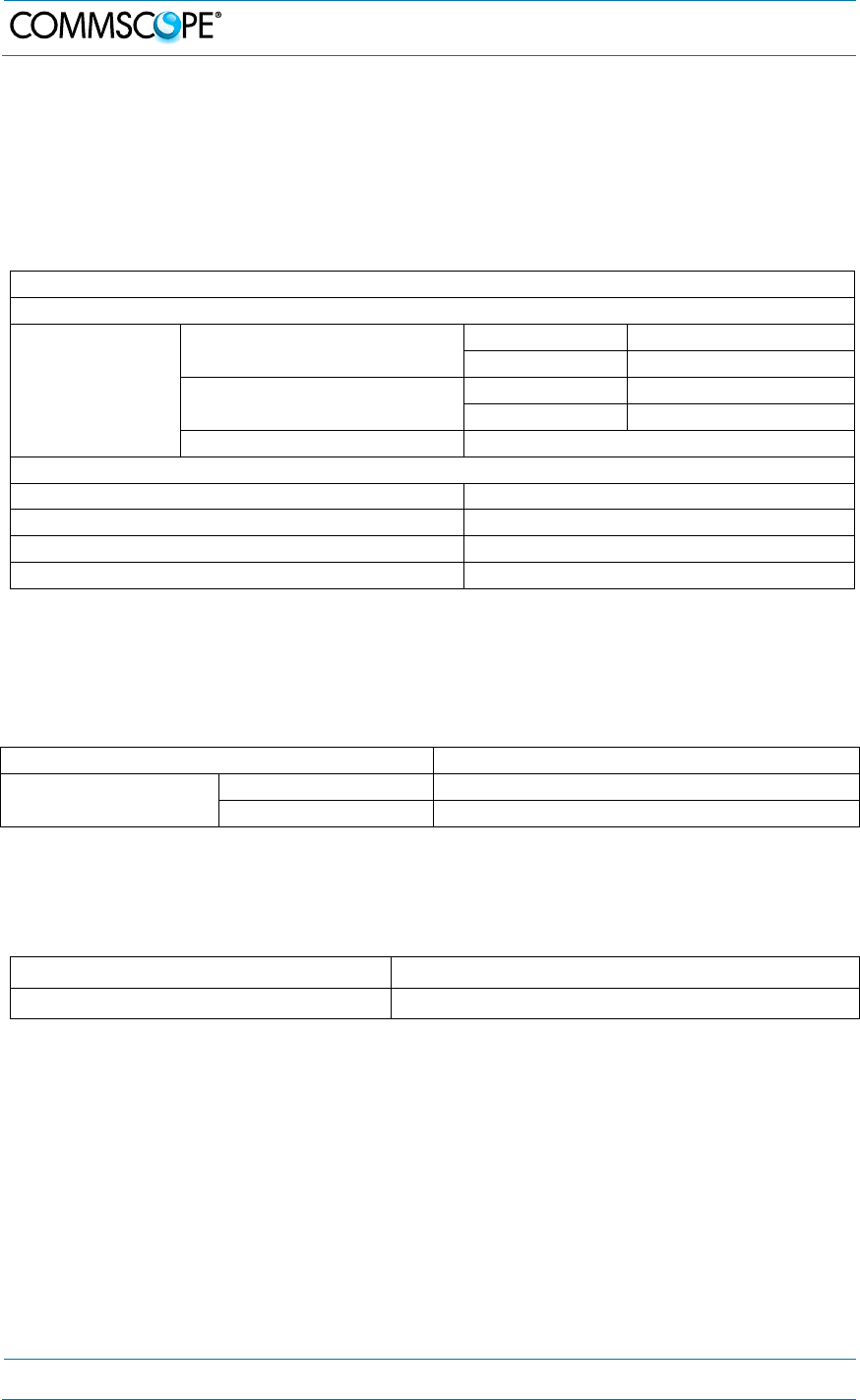
7. Appendix
Page 52 MF0150A2A.doc Manual for ION-M7P/85P/17EP/19P
7.2. Specifications
7.2.1. SW Requirements
Minimum SW requirements for basic support: ION-M SW V7.0.1
7.2.2. Electrical Specifications
ION-M7P/85P/17EP/19P
Electrical
Power supply
Mains power, AC nominal 100 Vac to 240 Vac
operating 85 Vac to 264 Vac
Mains power, DC nominal 48 Vdc to 60 Vdc
operating 36 Vdc to 72 Vdc
Power consumption 1050 W
Optical
Connectors E2000/APC 8°
Optical return loss 45 dB
Fiber type Single mode E9/125 mm
Optical link budget 0 dB to 10 dB
7.2.3. Environmental and Safety Specifications
Note: For detailed information, please refer to the Environmental and Safety
Specifications leaflet of the supplier, related to ETS 300 019 (European
Telecommunication Standard).
Operating temperature range -33° C to +50° C
Ingress protection RF part IP67
Fan part IP55
All data is subject to change without notice.
7.2.4. Mechanical Specifications
Height, width, depth * 824 x 176 x 220 mm (32.4 x 6.9 x 8.7 in)
Weight 31 kg (68.2 Ib)
* Spacing required: 50 mm (1.97 in) around unit
All data is subject to change without notice.
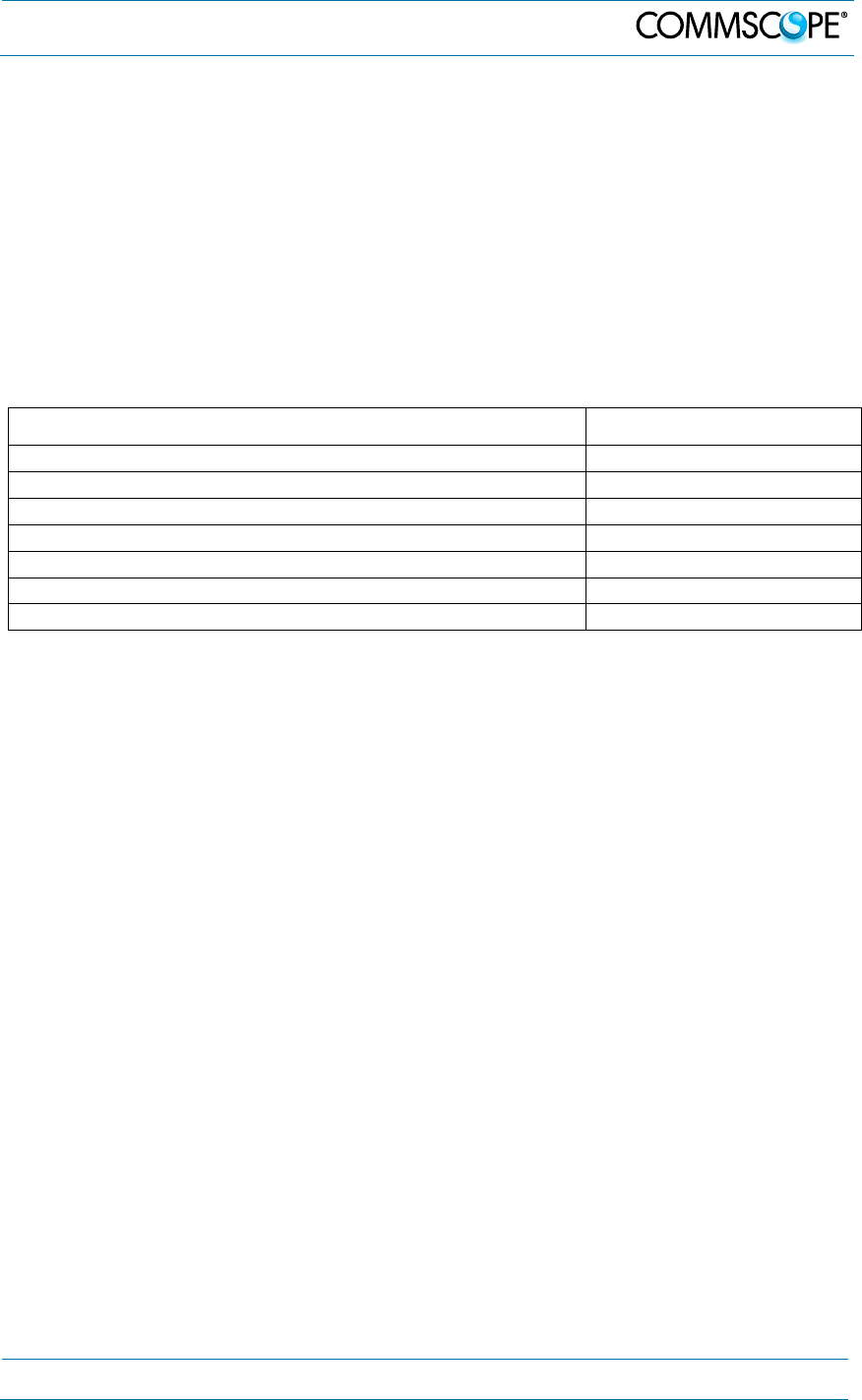
7. Appendix
MF0150A2A.doc Manual for ION-
M7P/85P/
17EP
/19P
Page 53
7.3. Spare Parts
The following list contains all parts available for the Remote Unit. The configuration of
the delivered unit meets the requirements of the customer and can differ depending
on the state of the delivery.
Maintenance of the RU should be performed on an FRU (Field Replaceable Unit)
basis only. Do not damage the warranty labels on the components, as this voids the
warranty.
If any FRU not contained in the following list needs to be replaced, please contact
customer service for additional instructions.
Spare Parts List of the Remote Unit ION-M7P/85P/17EP/19P
Designation: ID No.
Fan Unit M2-Cabinet 7661556-xx
Optical pigtail, 5 m 7704220
Optical pigtail kit, 5 m 7704209-xx
Pole-mounting kit M2-cab* 7661538
Pole-mounting kit M2-cab* with brackets 7690784
Wall-mounting kit M2-cab* 7661581
Manual for ION-M7P/85P/17EP/19P 7714242-00
* One of the three mounting kits has to be ordered separately. They are not contained within the
standard equipment.
The manufacturer reserves the right to replace the spare parts listed above by
equivalent substitutes.
Note: Only the spare parts listed above are FRUs and can be replaced by the
user. For replacement of any other parts, please send the entire
Remote Unit back to the manufacturer.

8. Index
Page 54 MF0150A2A.doc Manual for ION-M7P/85P/17EP/19P
8. Index
A
Alarms .................................................................... 45
External Inputs .................................................. 41
External Outputs ................................................ 42
Inputs (external) ................................................ 41
List ..................................................................... 45
Outputs .............................................................. 41
B
Block Diagram ........................................................ 16
C
CE Declaration of Conformity (DoC) ...................... 11
Cleaning the Heat Sink .......................................... 48
Commissioning
General .............................................................. 18
CommScope ........................................................... 11
Compliance .............................................................. 7
Connection Rules
Optical-Fiber Cables ......................................... 32
Connections
Antenna ............................................................. 27
Connector Flange .............................................. 25
Protective Plug .................................................. 34
Protective-Tube Kit ............................................ 36
Contact Addresses, Customer Support ................. 12
D
DC Mains Connector .............................................. 39
Declaration of Conformity (DoC) ............................ 11
E
External-Alarm Inputs & Outputs ........................... 41
F
Fiber-Optical Components (Installation, Cleaning) 33
Flange Connector (7 poles) ................................... 42
H
Health and Safety .................................................... 6
I
Illustrations ............................................................. 49
Installation
Electrical ........................................................... 24
Mechanical ........................................................ 18
M
Mains Connector .................................................... 37
Mains Power Connection....................................... 37
Mounting
Pole (with brackets) .......................................... 22
Pole (with screw bands) ................................... 21
Wall ................................................................... 20
P
Pin Assignment, External Alarms .......................... 42
Property Damage Warnings .................................... 6
R
Requirements, SW ................................................ 50
S
Spare Parts ............................................................ 51
Specifications
Electrical ........................................................... 50
Status LED ............................................................. 45
SW Requirements.................................................. 50
T
Troubleshooting ..................................................... 45