Andrew Wireless System M7P17HP ION-M Remote Unit for cellular systems User Manual MF0145AQA
Andrew Wireless System ION-M Remote Unit for cellular systems MF0145AQA
UserManual.wiki
>
Andrew Wireless System
>
M7P17HP User Manual
>
User manual
Contents
1.
Installation Instruction
2.
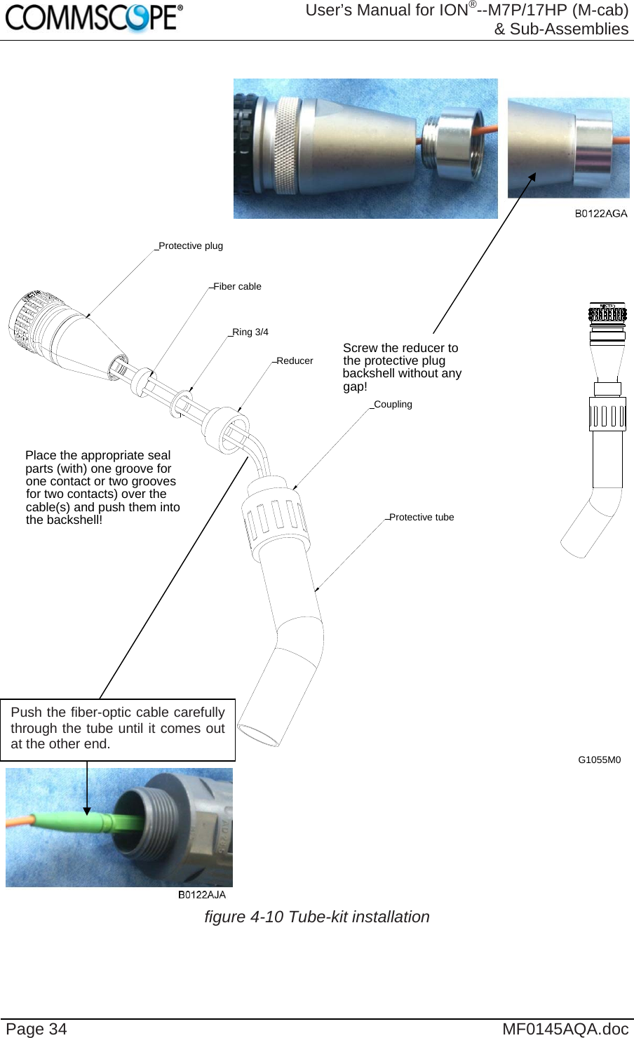
User manual
User manual
Navigation menu
Upload a User Manual
Namespaces
Wiki Guide
HTML
PDF
Info
Views
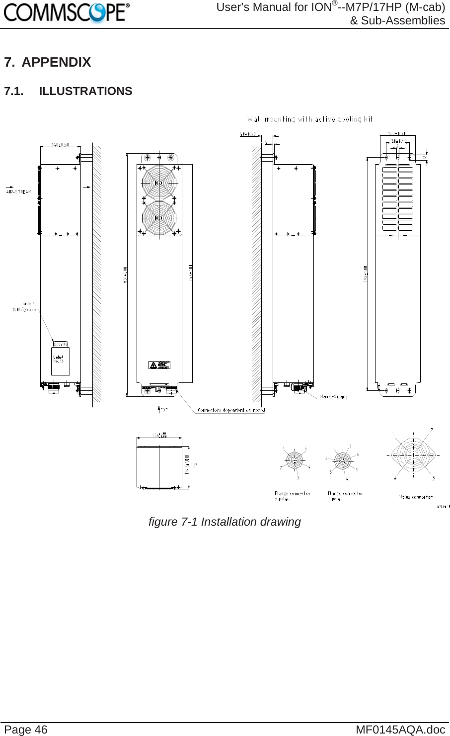
User Manual
Discussion / Help
Navigation
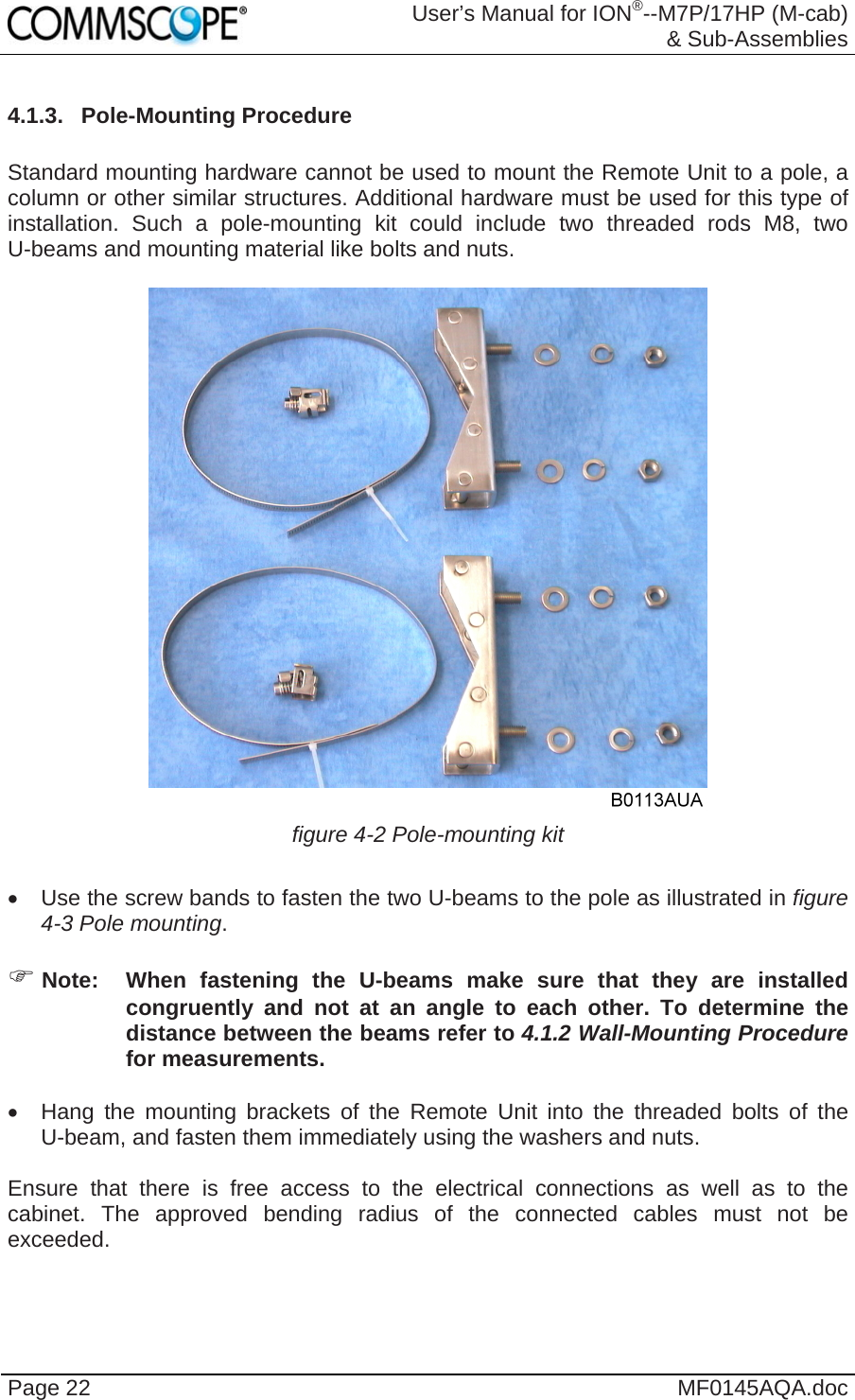
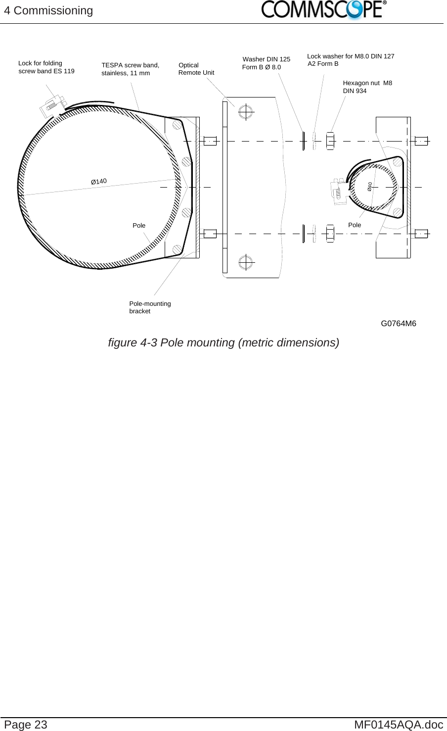
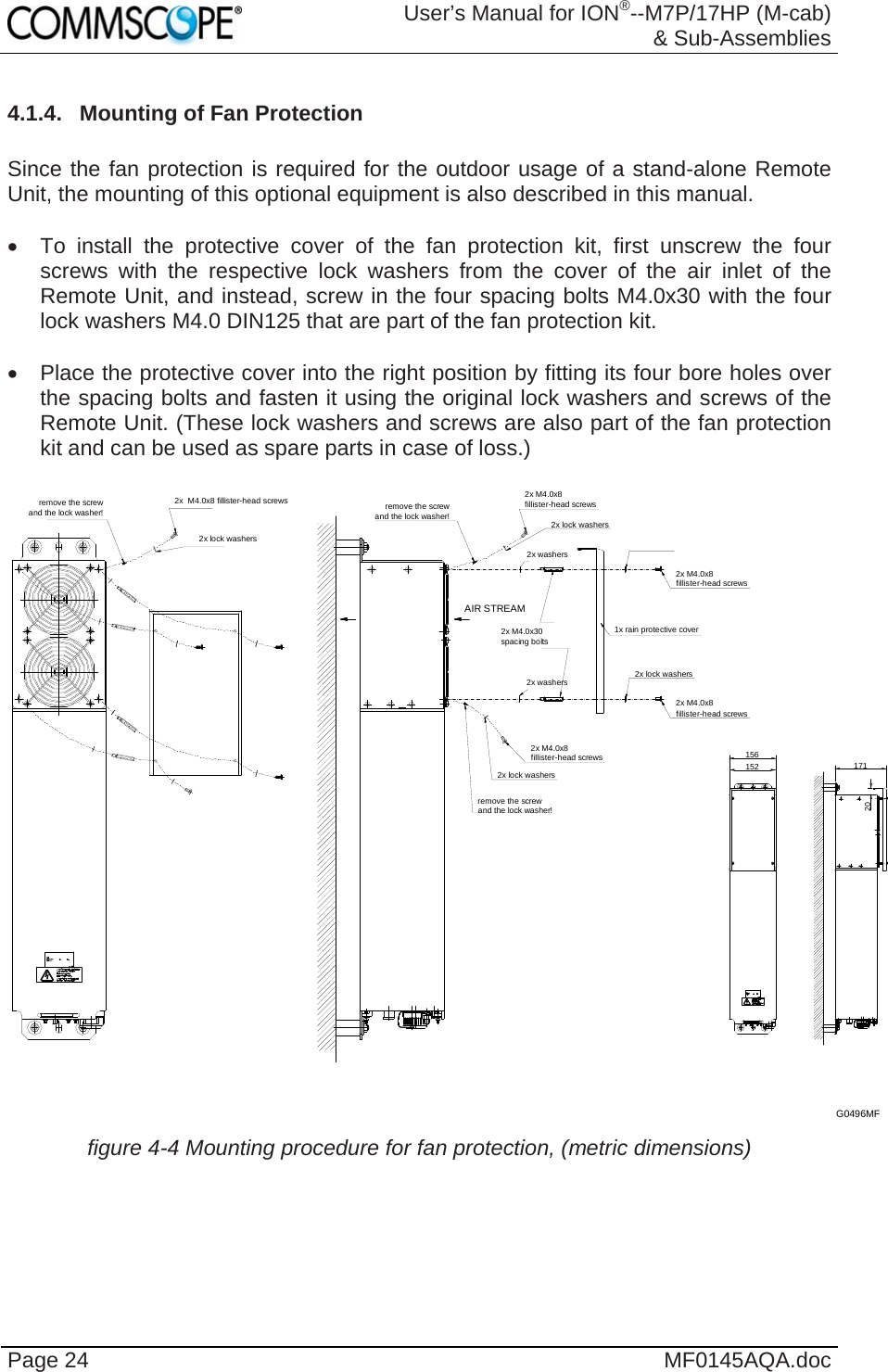
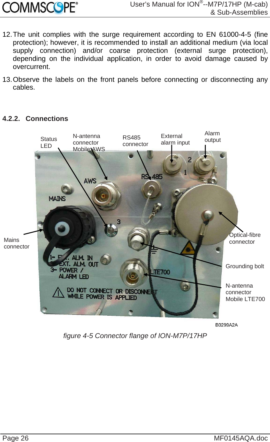
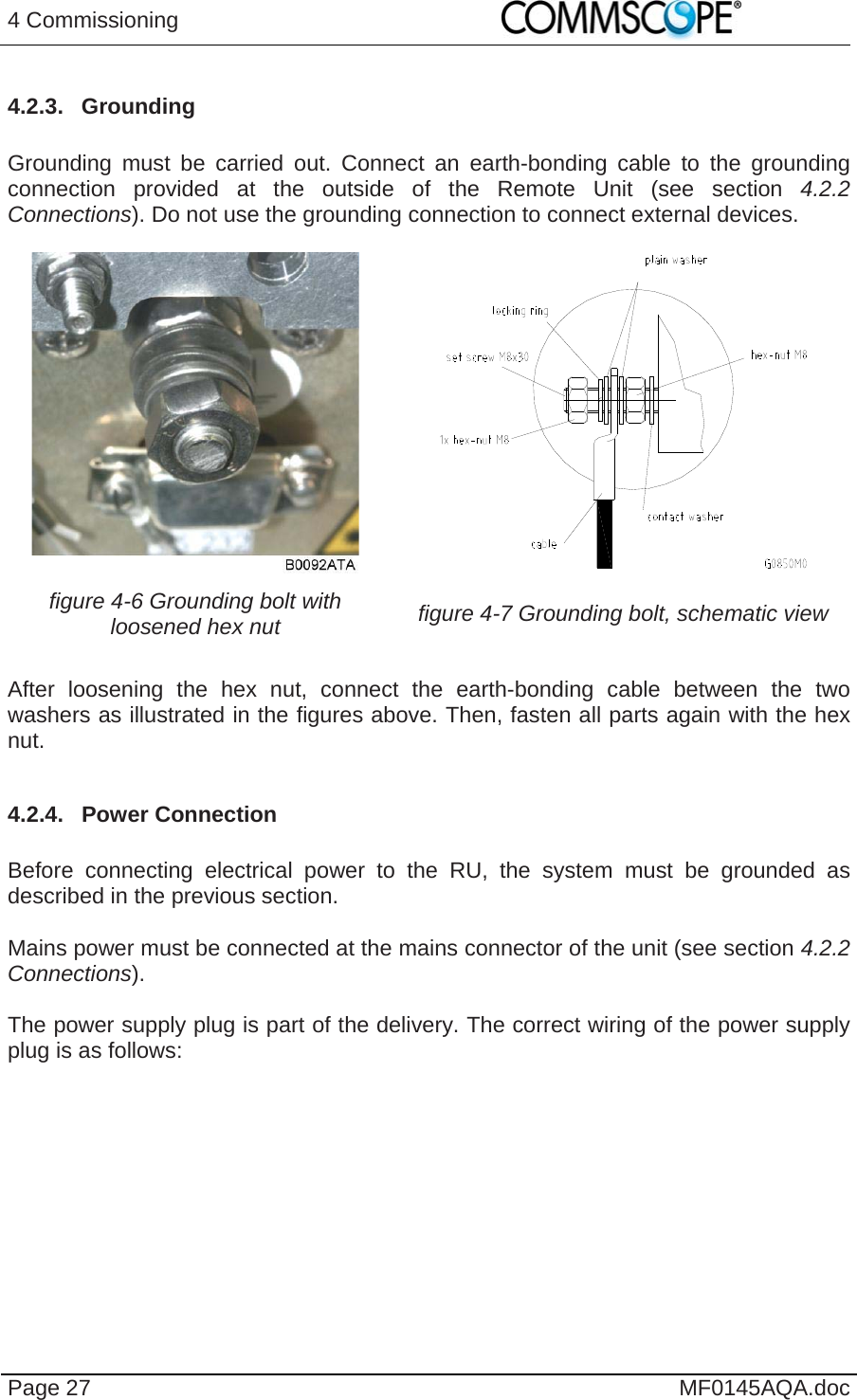
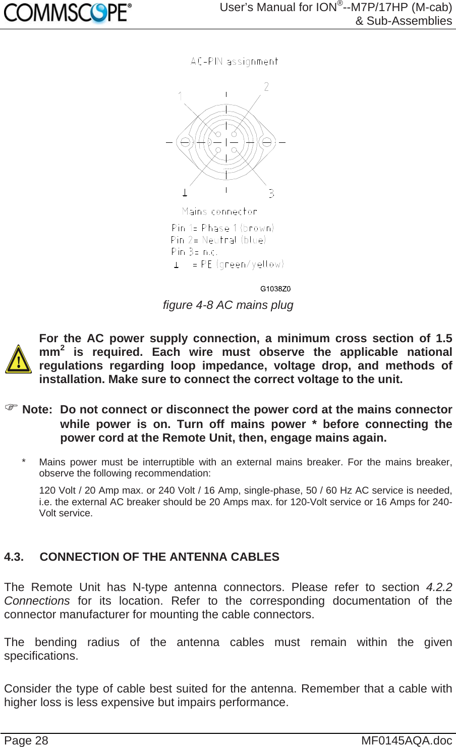
![1 General Page 9 12. Warning: For installations, which have to comply with FCC RF exposure requirements, the antenna selection and installation must be completed in a way to ensure compliance with those FCC requirements. Depending on the RF frequency, rated output power, antenna gain, and the loss between the repeater and antenna, the minimum distance D to be maintained between the antenna location and human beings is calculated according to this formula: ]/[][][24cmmWmWcm PDPD where P (mW) is the radiated power at the antenna, i.e. the max. rated repeater output power in addition to the antenna gain minus the loss between the repeater and the antenna. PD (mW/cm²) is the allowed Power Density limit acc. to 47 CFR 1.1310 (B) for general population / uncontrolled exposures which is o F (MHz) / 1500 for frequencies from 300MHz to 1500MHz o 1 for frequencies from 1500MHz to 100.000MHz RF exposure compliance may need to be addressed at the time of licensing, as required by the responsible FCC Bureau(s), including antenna co-location requirements of 1.1307(b)(3). 13. Caution: Installation of this equipment is in full responsibility of the installer, who has also the responsibility, that cables and couplers are calculated into the maximum gain of the antennas, so that this value, which is filed in the FCC Grant and can be requested from the FCC data base, is not exceeded. The industrial boosters are shipped only as a naked booster without any installation devices or antennas as it needs for professional installation. 14. Caution: Only suitably qualified personnel are allowed to work on this unit and only after becoming familiar with all safety notices, installation, operation and maintenance procedures contained in this manual. 15. Caution: Keep operating instructions within easy reach and make them available to all users. 16. Caution: Corresponding local particularities and regulations must be observed. For national deviations, please refer to the respective documents included in the manual CD that is delivered with the unit. 17. Caution: Although the remote unit is internally protected against overvoltage, it is strongly recommended to ground (earth) the antenna cables close to the repeater’s antenna connectors for protection against atmospheric discharge. 18. Caution: ESD precautions must be observed! Before commencing maintenance work, use the available grounding (earthing) system to connect ESD protection measures.](https://usermanual.wiki/Andrew-Wireless-System/M7P17HP.User-manual/User-Guide-2097407-Page-9.png)