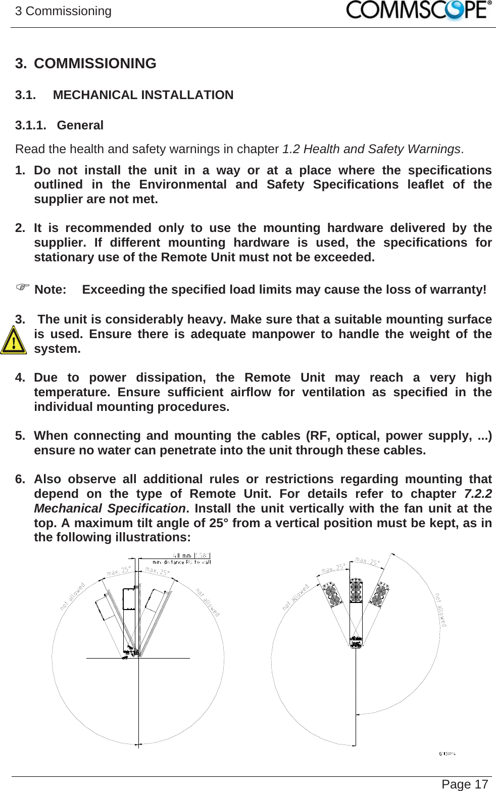
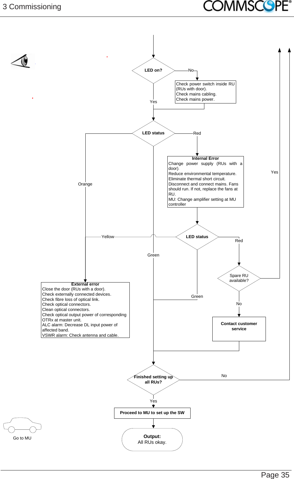
Andrew Wireless System ML78519P ION M remote unit for cellular networks User Manual User s Manual for Remote Unit
Andrew Wireless System ION M remote unit for cellular networks User s Manual for Remote Unit
UserManual.wiki
>
Andrew Wireless System
>
ML78519P User Manual
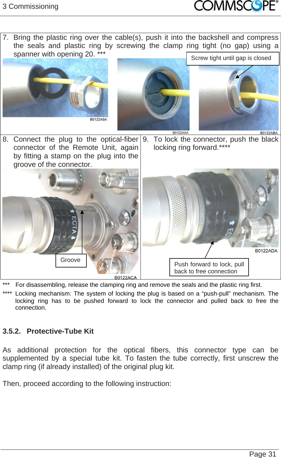
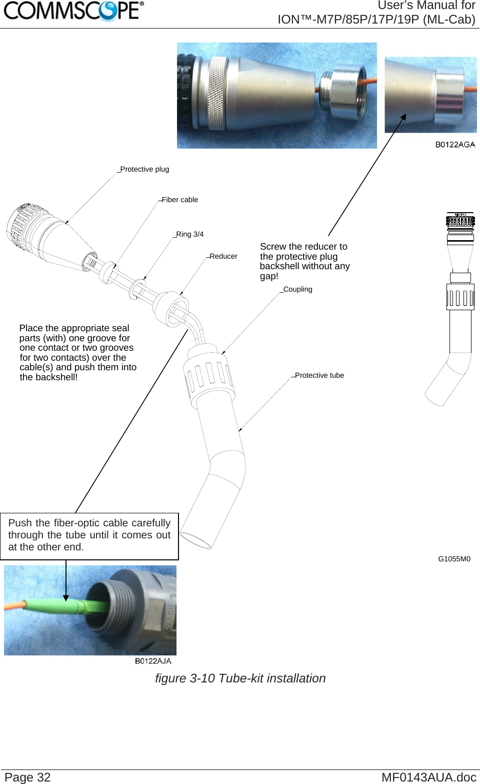
user manual
Navigation menu
Upload a User Manual
Namespaces
Wiki Guide
HTML
PDF
Info
Views
User Manual
Discussion / Help
Navigation