Andrew Wireless System TFAHES7850 ION-B Remote Unit for cellular systems User Manual Manual TFAH ES70 80 50
Andrew Wireless System ION-B Remote Unit for cellular systems Manual TFAH ES70 80 50
Contents
- 1. user manual
- 2. installation instruction
user manual
Page 1
Manual
for
TFAH-ES70/80/50
and
TFAH-ES70/80
MN024-15

User’s Manual for ION-B Systems
Page 2 Manual TFAH-
ES70_80_50.doc
DISCLAIMER:
This document has been developed by CommScope, and is intended for the use of its
customers and customer support personnel. The information in this document is subject to
change without notice. While every effort has been made to eliminate errors, CommScope
disclaims liability for any difficulties arising from the interpretation of the information
contained herein. The information contained herein does not claim to cover all details or
variations in equipment, nor to provide for every possible incident to be met in connection
with installation, operation, or maintenance. This document describes the performance of the
product under the defined operational conditions and does not cover the performance under
adverse or disturbed conditions. Should further information be desired, or should particular
problems arise which are not covered sufficiently for the purchaser’s purposes, contact
CommScope.
CommScope reserves the right to change all hardware and software characteristics without
notice.
COPYRIGHT:
© Copyright 2013 CommScope Inc. All Rights Reserved.
This document is protected by copyright. No part of this document may be reproduced,
stored in a retrieval system, or transmitted, in any form or by any means, electronic,
mechanical photocopying, recording, or otherwise without the prior written permission of
CommScope.
TRADEMARKS
All trademarks identified by ® or ™ are registered trademarks or trademarks, respectively, of
CommScope. Names of products mentioned herein are used for identification purposes only
and may be trademarks and / or registered trademarks of their respective companies.
Andrew Wireless Systems GmbH, 12-December-2013

Page 3
TABLE OF CONTENTS
1.1.About CommScope 5
1.2.International Contact Addresses for Customer Support 6
2.1.Case U Remote Unit 9
2.1.1.Specifications 9
2.1.2.Health and Safety 12
2.1.3.TFAx Case U Mechanical Installation 15
2.1.4.Wall Mounting Procedure 18
2.1.5.TFAx Case U Electrical Installation 21
2.1.5.1.General 21
2.1.5.2.Grounding (Earthing) 22
2.1.5.3.Mains Power Connection 23
2.1.5.4.Antenna Connection 26
2.1.5.5.Alarm Ports 28
2.2.Low Power RU Optical Installation 29
2.2.1.Optical-Fiber-Cable Connection - Rules 29
2.2.2.Optical cable installation 31
2.2.3.RU Power Supply Replacement 34
3.TECHNICAL SUPPORT 38
3.1.Contact Addresses 38
3.2.Returning Equipment 39

User’s Manual for ION-B Systems
Page 4 Manual TFAH-
ES70_80_50.doc
FIGURES AND TABLES
Figure 4-58 Case U Remote Unit ............................................................................................. 9
Figure 4-59 Case U connectors ............................................................................................. 10
Figure 4-60 Wall-mounting bracket ........................................................................................ 16
Figure 4-61 RU threaded pin power supply side .................................................................... 17
Figure 4-62 RU threaded pin narrow side .............................................................................. 17
Figure 4-63 Place RU onto wall mounting bracket ................................................................. 18
Figure 4-64 Install M6x12 screws and washers for single mount ........................................... 19
Figure 4-65 Attach M6 nut to threaded pins for single mount ................................................ 19
Figure 4-66 Completed RU Mount ......................................................................................... 20
Figure 4-67 Grounding bolts ................................................................................................... 22
Figure 4-68 Grounding bolt, schematic view .......................................................................... 22
Figure 4-69 AC power cable ................................................................................................... 23
Figure 4-70 DC power cable .................................................................................................. 23
Figure 4-71 Vdc/100 power cable .......................................................................................... 24
Figure 4-72 Connect Mains plug ............................................................................................ 25
Figure 4-73 N-type antenna connection ................................................................................. 27
Figure 4-74 Alarm Connector ................................................................................................. 28
Figure 4-75 Remove optics cover .......................................................................................... 31
Figure 4-76 Remove sealing nut ............................................................................................ 31
Figure 4-77 Split-seal and clamp jacket ................................................................................. 32
Figure 4-78 Optical cables connected .................................................................................... 32
Figure 4-79 Place cables into split-seal .................................................................................. 33
Figure 4-80 Optical cable installed ......................................................................................... 33
Figure 4-81 Disconnect Mains power ..................................................................................... 34
Figure 4-82 RU power supply location ................................................................................... 34
Figure 4-83 8 RU power supply screws ................................................................................. 35
Figure 4-84 RU power supply with cables .............................................................................. 35
Figure 4-85 RU power supply input cable .............................................................................. 35
Figure 4-86 RU power supply output cable ............................................................................ 36
Figure 4-87 RU with power supply removed .......................................................................... 36
Figure 4-88 RU with replacement power supply .................................................................... 36
Figure 4-89 RU insert power supply ....................................................................................... 37
Figure 4-90 Reconnect Mains power ..................................................................................... 37
Table1 List of international contact addresses ......................................................................... 8
Table 6 Specified torques ....................................................................................................... 15
Table 7 AC power cable ......................................................................................................... 23
Table 8 DC power cable ......................................................................................................... 23
Table 9 Vdc/100 power cable ................................................................................................. 24
Table 10 Alarm Connector ..................................................................................................... 28

User’s Manual for ION-B Systems
Page 5
1.1. ABOUT COMMSCOPE
CommScope is the foremost supplier of one-stop, end-to-end radio frequency (RF)
solutions. Part of the CommScope portfolio are complete solutions for wireless
infrastructure from top-of-the-tower base station antennas to cable systems and
cabinets, RF site solutions, signal distribution, and network optimization.
CommScope has global engineering and manufacturing facilities. In addition, it
maintains field engineering offices throughout the world.
Andrew Wireless Systems GmbH based in Buchdorf/ Germany, which is part of
CommScope, is a leading manufacturer of coverage equipment for mobile radio
networks, specializing in high performance, RF and optical repeaters. Our optical
distributed networks and RF repeater systems provide coverage and capacity
solution for wireless networks in both indoor installations and outdoor environments,
e.g. tunnels, subways, in-trains, airport buildings, stadiums, skyscrapers, shopping
malls, hotels and conference rooms.
Andrew Wireless Systems GmbH operates a quality management system in
compliance with the requirements of ISO 9001 and TL 9000. All equipment is
manufactured using highly reliable material. To maintain highest quality of the
products, comprehensive quality monitoring is conducted at all fabrication stages.
Finished products leave the factory only after a thorough final acceptance test,
accompanied by a test certificate guaranteeing optimal operation.
This product meets the requirements of the R&TTE directive and the Declaration of
Conformity (DoC) itself. A current version of the CE DoC is included in this manual
CD delivered *. Any updated version of the DoC is available upon request from the
local sales offices or directly from CommScope via the local Customer Support at
one of the addresses listed in the following chapter.
According to the DoC, our "CE"-marked equipment can be used in all member
states of the European Union.
Note: Exceptions of and national deviations from this intended use may be
possible. To observe corresponding local particularities and
regulations, please refer to the respective documents (also in
national language) which are included in the manual CD delivered.
* In case the Declaration of Conformity (DoC) for the product was not included in the manual CD
delivered, it is available upon request from the local sales offices or directly from CommScope at
one of the addresses listed in the following chapter.
To make the most of this product, we recommend you carefully read the instructions
in this manual and commission the system only according to these instructions.
For technical assistance and support, please also contact the local office or
CommScope directly at one of the addresses listed in the following chapter.
User’s Manual for ION-B Systems
Page 6 Manual TFAH-
ES70_80_50.doc
1.2. INTERNATIONAL CONTACT ADDRESSES FOR CUSTOMER SUPPORT
Americas:
Canada
United States
CommScope Canada Andrew LLC, A CommScope Company
Mail
505 Consumers Road, Suite 803
Toronto M2J 4V8
Canada
Mail
620 North Greenfield Parkway
Garner, NC 27529
U.S.A.
Phone +1-905-878-3457 (Office)
+1-416-721-5058 (Cell) Phone +1-888-297-6433
Fax +1-905-878-3297 Fax +1-919-329-8950
E-mail wisupport@commscope.com E-mail wisupport@commscope.com
Caribbean & South American Region
(CALA)
Caribbean (CALA) & Central American Region
CommScope Cabos do Brasil Ltda. CommScope Mexico S.A. de C.V.
Mail
CALA Tech Support for Distributed
Coverage & Capacity Solutions
(DCCS) products:
Rua Guaporanga, 49
Praça Seca – Rio de Janeiro – RJ
ZIP: 21320-180
Brazil
Mail
CALA Tech Support for Distributed
Coverage & Capacity Solutions
(DCCS) products:
Av. Insurgentes Sur 688, Piso 6
Col. Del Valle, CP: 03100
Mexico City
Mexico
Phone +1-815-546-7154 (Cell)
+55-15-9104-7722 (Office) Phone +52-1-55-5419-5260 (Cell)
+52-55-1346-1900 (Office)
Fax + 55-15-2102-4001 Fax +52-55-1346-1901
E-mail wisupport@commscope.com E-mail wisupport@commscope.com
APAC Countries:
China, India and Rest of Asia
Australia & New Zealand
Andrew International Corporation Andrew Corporation (Australia) Pty Ltd.
Mail
Room 915, 9/F
Chevalier Commercial Centre
8 Wang Hoi Rd
Kowloon Bay
Hong Kong
Mail
Unit 1
153 Barry Road
Campbellfield
VIC 3061
Australia
Phone +852-3106-6100 Phone +613-9300-7969
Fax +852-2751-7800 Fax +613-9357-9110
E-mail wisupport.China@commscope.com E-mail wisupport.Australia@commscope.com

User’s Manual for ION-B Systems
Page 7
Europe:
United Kingdom
Scandinavia
Andrew Wireless Systems UK Ltd
A
ndrew Norway (AMNW)
Mail
Unit 15, Ilex Building
Mulberry Business Park
Fishponds Road
Wokingham Berkshire
RG41 2GY
England
Mail
P.O. Box 3066
Osloveien 10
Hoenefoss 3501
Norway
Phone +44-1189-366-792 Phone + 47 32-12-3530
Fax +44-1189-366-773 Fax + 47 32-12-3531
E-mail wisupport.uk@commscope.com E-mail wisupport@commscope.com
Germany
France
Andrew Wireless Systems GmbH CommScope France
Mail
Industriering 10
86675 Buchdorf
Germany
Mail
Immeuble Le Lavoisier
4, Place des Vosges
92052 Courbevoie
France
Phone +49-9099-69-0 Phone +33-1 82 97 04 00
Fax +49-9099-69-930 Fax +33-1 47 89 45 25
E-mail wisupport@commscope.com E-mail wisupport@commscope.com
Austria
Switzerland
Andrew Wireless Systems (Austria) GmbH CommScope Wireless Systems AG
Mail
Weglgasse 10
2320 Wien-Schwechat
Austria
Mail
Tiergartenweg 1
CH-4710 Balsthal
Switzerland
Phone +43-1706-39-99-10 Phone +41-62-386-1260
Fax +43-1706-39-99-9 Fax +41-62-386-1261
E-mail wisupport.austria@commscope.com E-mail wisupport.ch@commscope.com
Italy
Iberia Region - Spain & Portugal
CommScope Italy S.r.l., Faenza, Italy
A
ndrew España S.A.
A CommScope Company
Mail
Via Mengolina, 20
48018 Faenza (RA)
Italy
Mail
Avda. de Europa, 4 - 2ª pta.
Parque Empresarial de la Moraleja
Alcobendas, Madrid 28108
Spain
Phone +39-0546-697111 Phone +34-91-745-20 40
Fax +39-0546-682768 Fax +34-91-661-87 02
E-mail wisupport.italia@commscope.com E-mail wisupport.iberia@commscope.com

User’s Manual for ION-B Systems
Page 8 Manual TFAH-
ES70_80_50.doc
Czech Republic
CommScope Solutions Czech Republic
C-Com, spol. s r.o
Mail
U Moruší 888
53006 Pardubice
Czech Republic
Phone +49 871 9659171 (Office)
+49 171 4001166 (Mobile)
Fax +49 871 9659172
E-mail wisupport@commscope.com
Africa & Middle East:
Middle East & North Africa
South Africa
CommScope Solutions International Inc.
(Branch) Andrew Wireless Solutions Africa (PTY)
LTD
Mail
PO Box 48 78 22
Unit 3206, Floor 32,
Jumeirah Business Center 5,
Jumeirah Lakes Towers,
Dubai
United Arab Emirates
Mail
11 Commerce Crescent West
Eastgate, Sandton
PO Box 786117
Sandton 2146
South Africa
Phone +971 4 390 09 80 Phone + 27 11-719-6000
Fax +971 4 390 86 23 Fax + 27 11-444-5393
E-mail wisupport@commscope.com E-mail wisupport@commscope.com
Table1 List of international contact addresses
User’s Manual for ION-B Systems
Page 9
2.
2.1. CASE U REMOTE UNIT
2.1.1. Specifications
Dimensions: mm 500 x 480 x 205
(inches 19.7 x 18.9 x 8.1)
Weight: Please refer to the Remote Unit dedicated e-catalog entry in order to
know the updated data about the weight of your Case U Remote
Unit.
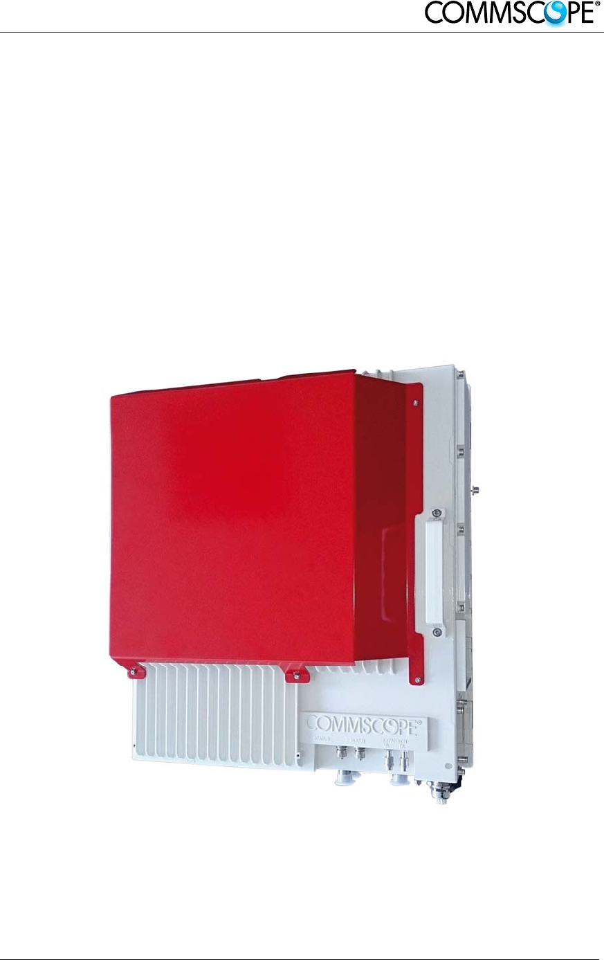
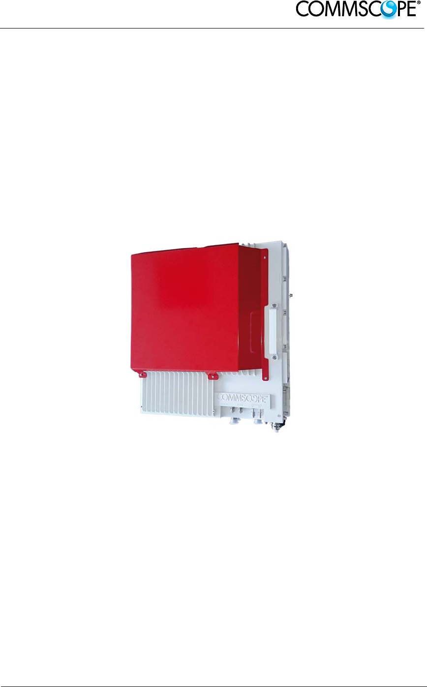
Figure 2-1 Case U Remote Unit
Case U Remote Units are available with and without the red cover, which serves for
indication of public safety services equipment.
User’s Manual for ION-B Systems
Page 10 Manual TFAH-
ES70_80_50.doc
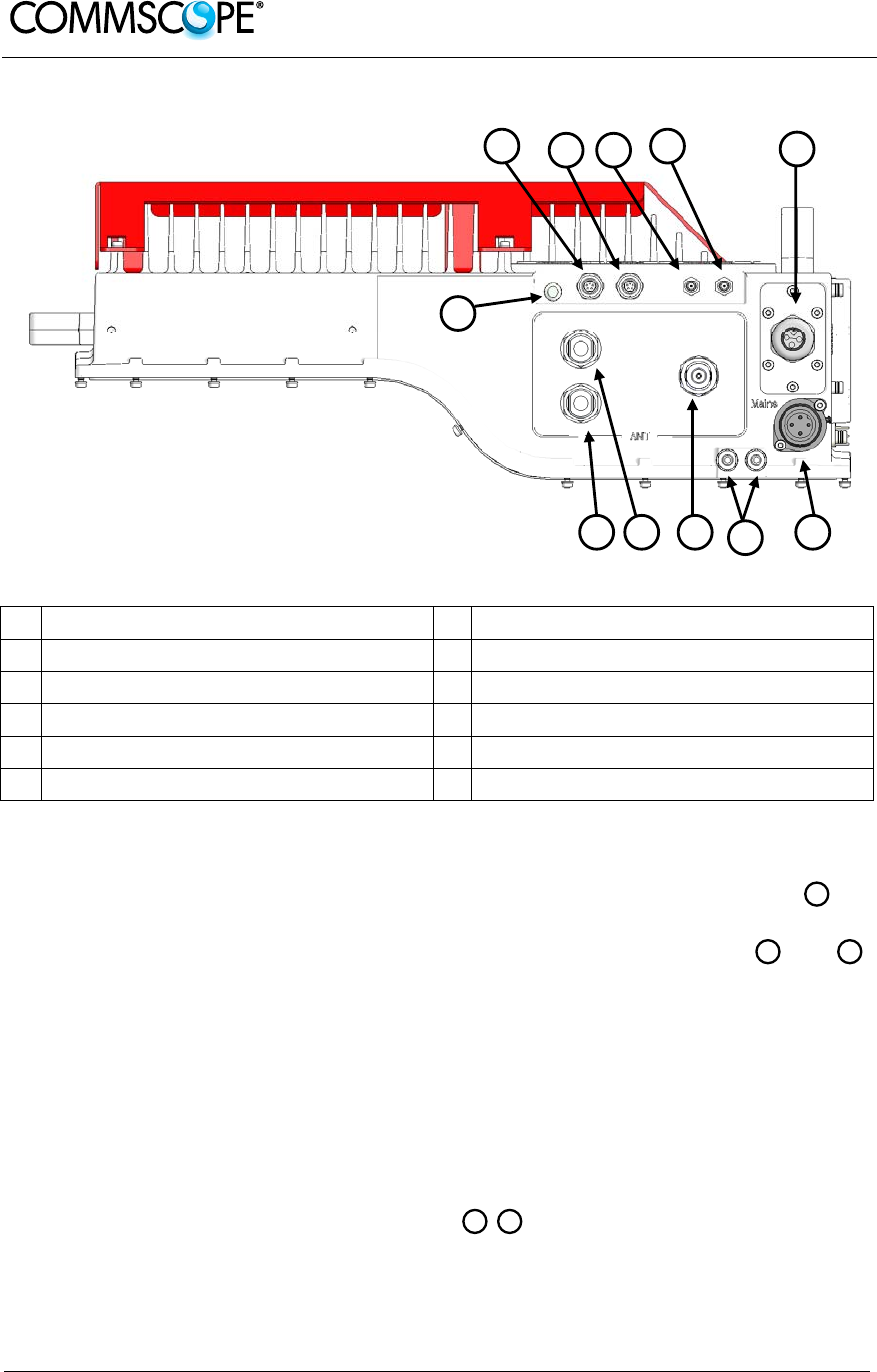
Figure 2-2 Case U connectors
A Status LED G Power supply connector
B Alarms lower band H Grounding bolts
C Alarms higher band(s) I UL/DL antenna port higher band(s)
D Expansion UL port J UL lower band, not connected in 2 band
E Expansion DL port K DL lower band, not connected in 2 band
F UL / DL optical ports
Antenna Port
In the two band configuration the RU has one duplexed N-female antenna port for
transmitting and receiving signals to and from distributed antennas. In the three band
configuration the RU also has two non-duplexed N-female antenna ports and
for UL and DL. These RF ports can be connected directly to an antenna (i.e. using
RF jumper cables) or through splitters, allowing additional antennas to be fed by the
RU.
Status LED
The status LED provides a visual warning of an alarm condition. The color of the LED
indicates the severity of the alarm.
Expansion Ports
The Expansion UL and Expansion DL ports are QMA female connectors that
are used to connect to a CommScope expansion unit to provide additional bands.
KJ
FD
I
A
BC D E
H GI J
F
K

User’s Manual for ION-B Systems
Page 11
Optical Ports
The LC-APC optical connectors are used to send and receive the signals between
the RU and the Master Unit’s OTRx modules.
A DL optical port receives downlink signals from the MU OTRx.
A UL optical port transmits uplink signals to the MU OTRx.
Mains Connector
The RU receives its power through the Mains connector . The type of connector is
dependent on the RU model. A 4-pin Amphenol connector is used for AC models and
standard DC models. A 7-pin Amphenol connector is used for DC models powered
by a dual cable supply.
Alarm connectors
The RU has two alarm relay outputs that can be used report alarms to external
devices. The Alarm connectors , lower band and , higher bands are 5-pin Binder
connectors.
C
F
B
G

User’s Manual for ION-B Systems
Page 12 Manual TFAH-
ES70_80_50.doc
2.1.2. Health and Safety
1. Danger: Obey all general and regional installation and safety regulations relating
to work on high voltage installations, as well as regulations covering correct use
of tools and personal protective equipment.
2. Danger: Before opening the unit, disconnect mains power.
3. Danger: Laser radiation! Do not stare into the beam; do not view it directly or with
optical instruments.
4. Danger: Due to power dissipation, the Remote Unit may reach a very high
temperature. Do not operate this equipment on or close to flammable materials.
Use caution when servicing the unit.
5. Warning: Read and obey all the warning labels attached to the unit. Make sure
that all warning labels are kept in a legible condition. Replace any missing or
damaged labels.
6. Warning: It is the responsibility of the network provider to implement prevention
measures to avoid health hazards associated with radiation from the antenna(s)
connected to the unit.
7. Warning: Only authorized and trained personnel are allowed to open the unit and
get access to the inside.
8. Warning: Only license holders for the respective frequency range are allowed to
operate this unit.
9. Warning: Make sure the repeater settings are correct for the intended use (refer
to the manufacturer product information) and regulatory requirements are met.
10. Warning: Use this equipment only for the purpose specified by the manufacturer.
Do not carry out any modifications or fit any spare parts, which are not sold or
recommended by the manufacturer. This could cause fires, electric shock, or
other injuries.
11. Warning: For installations which have to comply with European EN50385
exposure compliance requirements, the following Power Density limits/guidelines
(mW/cm²) according to ICNIRP are valid:
o 0.2 for frequencies from 10 MHz to 400 MHz
o F (MHz) / 2000 for frequencies from 400 MHz to 2 GHz
o 1 for frequencies from 2 GHz to 300 GHz

User’s Manual for ION-B Systems
Page 13
12. Warning: For installations, which have to comply with FCC RF exposure
requirements, the antenna selection and installation must be completed in a way
to ensure compliance with those FCC requirements. Depending on the RF
frequency, rated output power, antenna gain, and the loss between the repeater
and antenna, the minimum distance D to be maintained between the antenna
location and human beings is calculated according to this formula:
]/[
][
][
2
4cmmW
mW
cm PD
P
D
where
P (mW) is the radiated power at the antenna, i.e. the max. rated repeater
output power in addition to the antenna gain minus the loss between the
repeater and the antenna.
PD (mW/cm²) is the allowed Power Density limit acc. to 47 CFR 1.1310 (B)
for general population / uncontrolled exposures which is
o F (MHz) / 1500 for frequencies from 300MHz to 1500MHz
o 1 for frequencies from 1500MHz to 100.000MHz
RF exposure compliance may need to be addressed at the time of licensing, as
required by the responsible FCC Bureau(s), including antenna co-location
requirements of 1.1307(b)(3).
13. Caution: Installation of this equipment is in full responsibility of the installer, who
has also the responsibility, that cables and couplers are calculated into the
maximum gain of the antennas, so that this value, which is filed in the FCC Grant
and can be requested from the FCC data base, is not exceeded. The industrial
boosters are shipped only as a naked booster without any installation devices or
antennas as it needs for professional installation.
14. Caution: Only suitably qualified personnel are allowed to work on this unit and
only after becoming familiar with all safety notices, installation, operation and
maintenance procedures contained in this manual.
15. Caution: Keep operating instructions within easy reach and make them available
to all users.
16. Caution: Corresponding local particularities and regulations must be observed.
For national deviations, please refer to the respective documents included in the
manual CD that is delivered with the unit.
17. Caution: Although the Remote Unit is internally protected against overvoltage, it
is strongly recommended to ground (earth) the antenna cables close to the
repeater’s antenna connectors for protection against atmospheric discharge.
18. Caution: ESD precautions must be observed! Before commencing maintenance
work, use the available grounding (earthing) system to connect ESD protection
measures.
User’s Manual for ION-B Systems
Page 14 Manual TFAH-
ES70_80_50.doc
19. Note: For a Class A digital device or peripheral:
This equipment has been tested and found to comply with the limits for a Class A
digital device, pursuant to part 15 of the FCC Rules. These limits are designed to
provide reasonable protection against harmful interference when the equipment is
operated in a commercial environment. This equipment generates, uses, and can
radiate radio frequency energy and, if not installed and used in accordance with
the instruction manual, may cause harmful interference to radio communications.
Operation of this equipment in a residential area is likely to cause harmful
interference in which case the user will be required to correct the interference at
his own expense.
20. Note: This unit complies with European standard EN60950.
Equipment Symbols Used / Compliance
Please observe the meanings of the following symbols used in our equipment and
the compliance warnings:
Symbol Compliance Meaning / Warning
--- FCC
For industrial (Part 20) signal booster:
WARNING: This is NOT a CONSUMER device. It is
designed for installation by FCC LICENSEES and
QUALIFIED INSTALLERS. You MUST have an FCC
LICENSE or express consent of an FCC Licensee to
operate this device. Unauthorized use may result in
significant forfeiture penalties, including penalties in
excess of $100,000 for each continuing violation.
For (Part 90) signal booster:
WARNING: This is NOT a CONSUMER device. It is
designed for installation by FCC LICENSEES and
QUALIFIED INSTALLERS. You MUST have an FCC
LICENSE or express consent of an FCC Licensee to
operate this device. You MUST register Class B
signal boosters (as defined in 47 CFR 90.219) online
at www.fcc.gov/signal-boosters/registration.
Unauthorized use may result in significant forfeiture
penalties, including penalties in excess of $100,000
for each continuing violation.
CE
Alert sign to R&TTE
To be sold exclusively to mobile operators or
authorized installers – no harmonized frequency
bands, operation requires license. Intended use: EU
and EFTA countries
Indicates conformity with the R&TTE directive
1999/5/EC certified by the notified body no. 0700.
User’s Manual for ION-B Systems
Page 15
2.1.3. TFAx Case U Mechanical Installation
Each Case U Remote Unit kit includes:
1. a RU TFAx
2. a power supply plug
1. Warning: Do not install the unit in a way or at a place where the
specifications outlined in the Environmental and Safety Specifications
leaflet of the supplier are not met.
2. WARNING: IMPROPER INSTALLATION CAN LEAD TO EQUIPMENT
FALLING CAUSING SERIOUS PERSONAL INJURY OR DAMAGE TO
EQUIPMENT. The installer must verify that the supporting surface will safely
support the combined load of the electronic equipment and all attached
hardware and components. The screws and dowels (wall anchors) used
should also be appropriate for the structure of the supporting wall.
3. Warning: It is recommended to use the mounting hardware delivered by the
manufacturer only. If different mounting hardware is used, the
specifications for stationary use of the Remote Unit must not be exceeded.
4. Note: Exceeding the specified load limits may cause the loss of
warranty!
5. Warning: The unit is considerably heavy. Ensure there is adequate
manpower to handle the weight of the system.
6. Caution: Due to power dissipation, the Remote Unit may reach a very high
temperature. Ensure sufficient airflow for ventilation.
7. Note: When connecting and mounting the cables (RF, optical, mains, ...)
ensure that no water can penetrate into the unit through these cables.
8. Note: Observe all additional rules or restrictions regarding mounting that
apply to specific Remote Unit types.
If any different or additional mounting material is used, ensure that the mounting
remains as safe as the mounting designed by the manufacturer. Ensure that the
static and dynamic strengths are adequate for the environmental conditions of the
site. The mounting itself must not vibrate, swing or move in any way that might cause
damage to the Remote Unit.
Specified torques must be observed for certain mounting procedures according to the
following table:
Type Pins Hex nuts Screws
Thread M 6 M 6 M6
Specified torques 3.3 Nm 3.3 Nm 3.3 Nm
Table 2 Specified torques
User’s Manual for ION-B Systems
Page 16 Manual TFAH-
ES70_80_50.doc
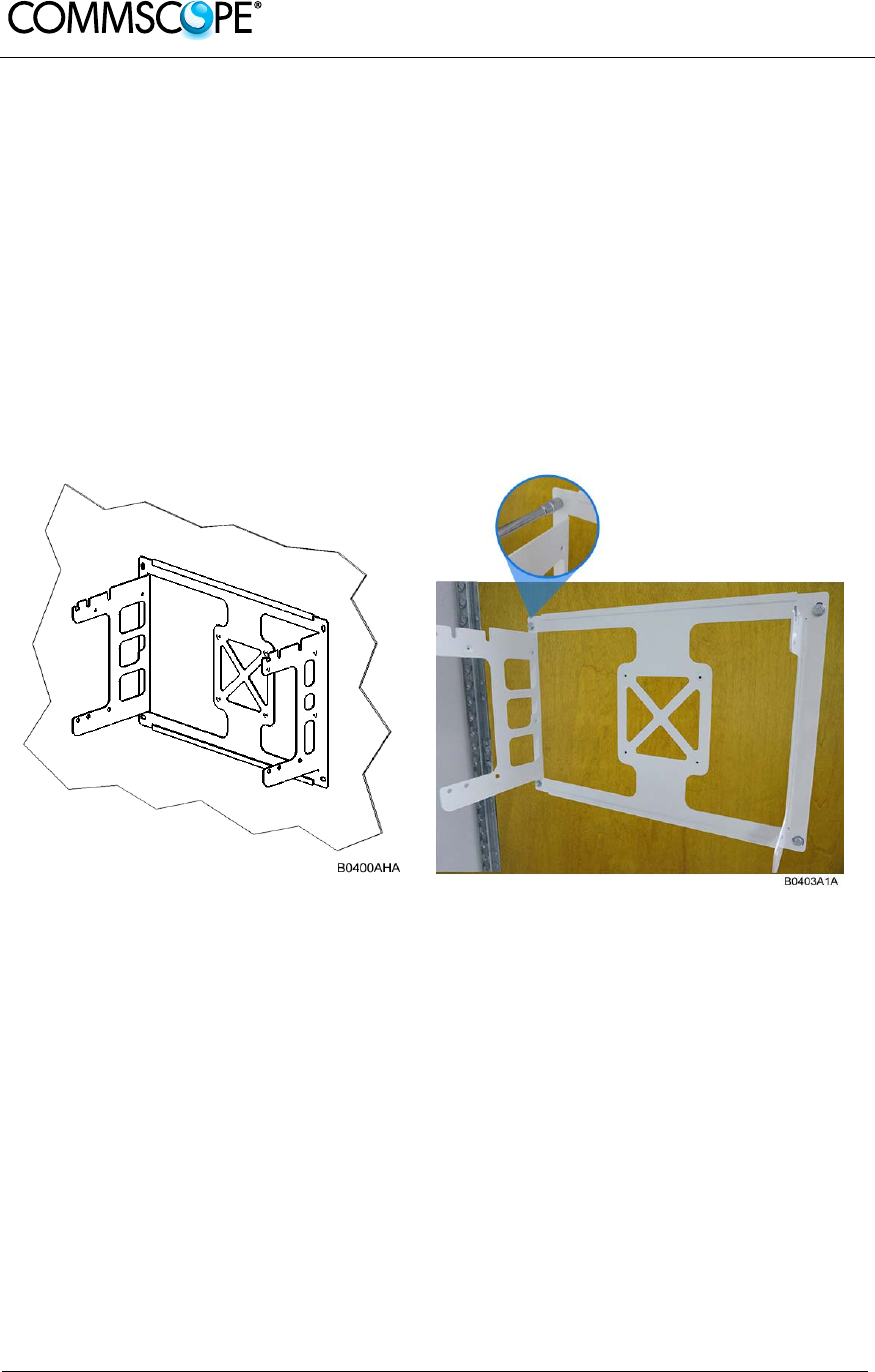
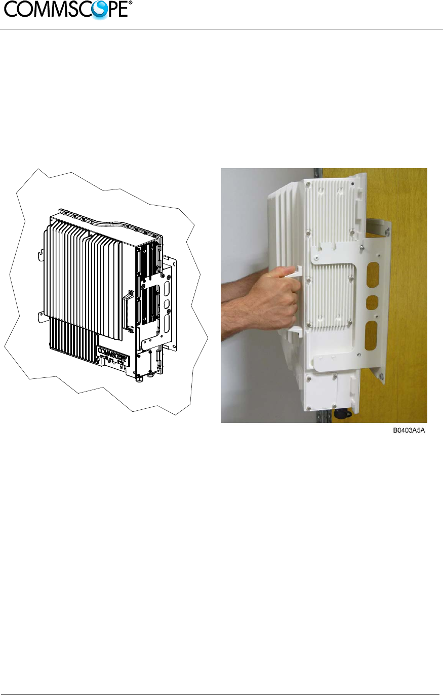
Wall-Mounting
1. Check the suitability of the wall-mounting kit and the wall.
2. Install the wall-mounting bracket using 4 M6 screw anchors (not included*) or
suitable lag bolts according to the drilling layout. Confirm that the bracket is
securely fastened to the wall. Installer must verify that the supporting surface
will safely support the combined load of the electronic equipment and all
attached hardware and components.
* The M6 screw anchors are not included as part of the RU delivery because
the suitable type depends on the on-site conditions (wall structure and materials).
Use screw anchors that are appropriate for the mounting surface.
Figure 2-3 Wall-mounting bracket
User’s Manual for ION-B Systems
Page 17
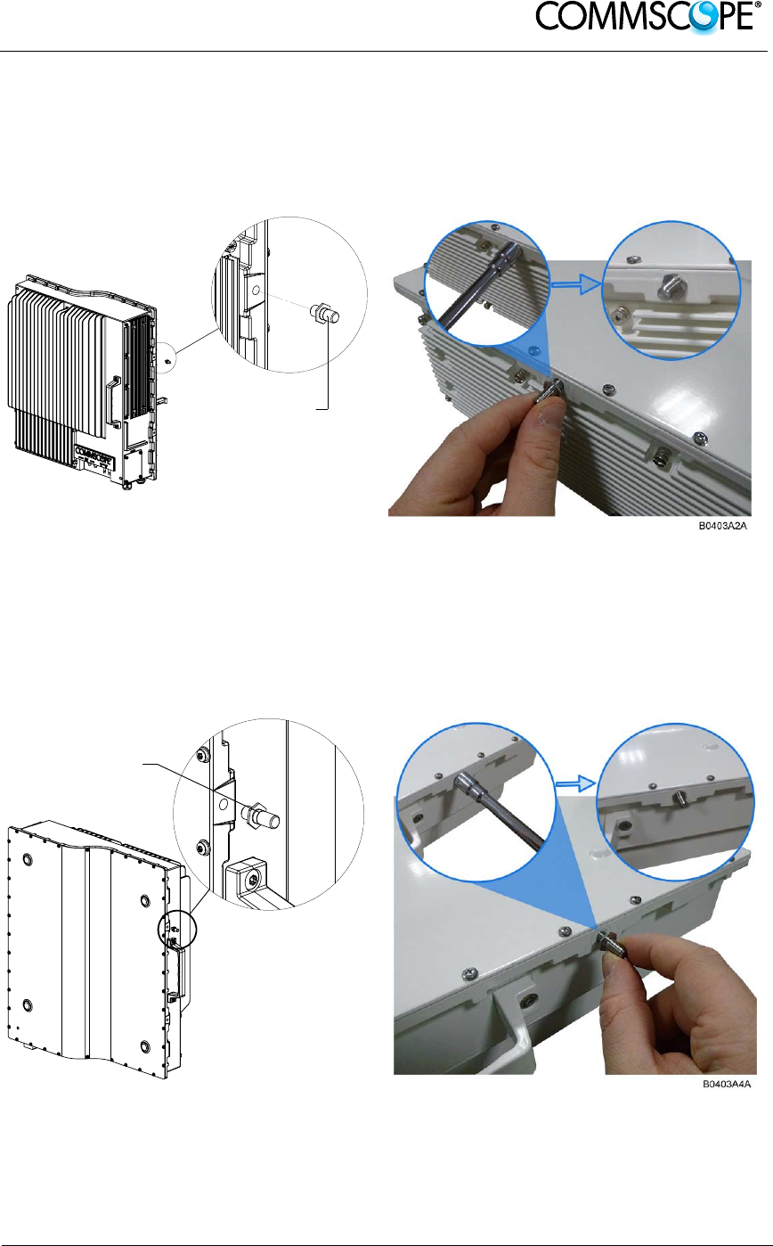
3. Attach an M6 threaded pin to the Remote Unit by inserting it into the threaded
hole adjacent to the power supply and turning it clockwise. Tighten the pin
securely with a socket wrench.
M6 threaded pin
B0400AJA
Figure 2-4 RU threaded pin power supply side
4. Attach an M6 threaded pin to the Remote Unit by inserting it into the threaded
hole above the handle and turning it clockwise. Tighten the pin securely with a
socket wrench.
M6 threaded pin
B0403A3A
Figure 2-5 RU threaded pin narrow side
User’s Manual for ION-B Systems
Page 18 Manual TFAH-
ES70_80_50.doc
2.1.4. Wall Mounting Procedure
1. Follow the instructions for mounting the bracket and installing the threaded
pins in chapter 0.
2. Install the Remote Unit on the wall-mounting bracket by lifting the RU into
place and using both handles and lowering it down onto the bracket. The M6
pins must align with the slots in the bracket to support the RU.
B0400AKA
Figure 2-6 Place RU onto wall mounting bracket
User’s Manual for ION-B Systems
Page 19
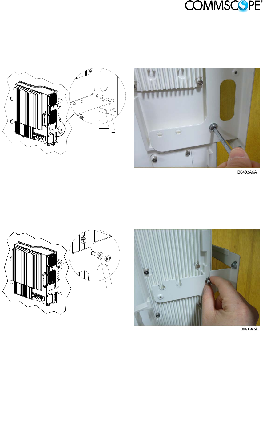
3. Fasten the lower section of the Remote Unit to the bracket using a washer
and an M6x12 screw (on both sides). Slide a washer over each screw and
then insert the screw and tighten it securely.
B0400AL
A
M6x12 screw
Washer
Figure 2-7 Install M6x12 screws and washers for single mount
4. Fasten the Remote Unit to the bracket using a washer and M6 nut. Slide the
washer over the threaded pins that you installed previously (chapter 0) and
then screw the nut onto the pins (on both sides) and tighten securely.
B0400AMA
M6 nut
Washer
Figure 2-8 Attach M6 nut to threaded pins for single mount
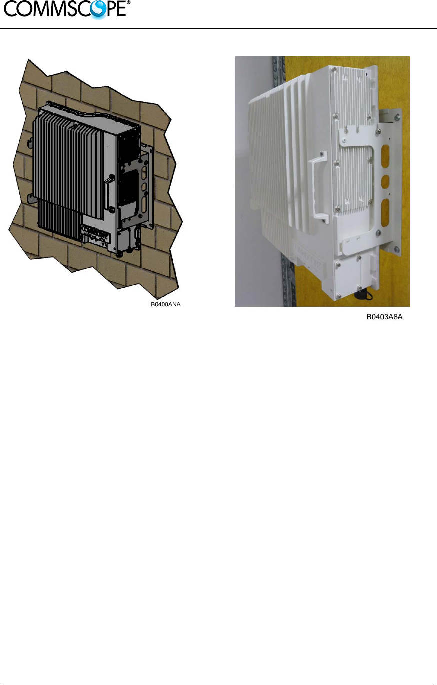
5. Confirm that all screws and nuts have been fastened and the unit is securely
mounted to the wall.
User’s Manual for ION-B Systems
Page 20 Manual TFAH-
ES70_80_50.doc
Figure 2-9 Completed RU Mount

User’s Manual for ION-B Systems
Page 21
2.1.5. TFAx Case U Electrical Installation
2.1.5.1. General
1. Warning: This unit contains dangerous voltages. Loss of life, severe personal
injury, or property damage can be the result if the instructions contained in this
manual are not followed.
2. Caution: It is compulsory to ground (earth) the unit before connecting the power
supply. A grounding bolt is provided on the cabinet to connect the ground-
bonding cable.
3. Caution: Although the remote unit is internally protected against overvoltage, it is
strongly recommended to ground (earth) the antenna cables close to the antenna
connectors of the remote unit for protection against atmospheric discharge. In
areas with strong lightning, it is strongly recommended to install additional
lightning protection.
4. Caution: If the mains connector of the remote unit is not easily accessible, a
disconnect device in the mains power circuit must be provided within easy reach.
5. Caution: Before connecting or disconnecting the mains connector at the remote
unit, ensure that mains power supply is disconnected.
6. Caution: Make sure that an appropriate circuit breaker acting as a disconnect
device (as required by IEC/EN60950-1) and an overcurrent limiting device are
connected between mains power and the Remote Unit.
7. Caution: A connection of the mains supply to a power socket requires the power
socket to be nearby the remote unit.
8. Caution: Incorrectly wired connections can destroy electrical and electronic
components.
9. Caution: To avoid corrosion at the connectors caused by electrochemical
processes, the material of the cable connectors must not cause a higher potential
difference than 0.6 V (see electrochemical contact series).
10. Note: Use an appropriate torque wrench for the coupling torque of N-type
connectors (2 Nm / 1.5 lb/ft), with 13/16 in opening to tighten the N-type antenna
connectors. For example, use torque wrench of item no. 244379 available from
the CommScope e-catalog. Do NOT use your hands or any other tool (e.g. a pair
of pliers)! This might cause damage to the connector and lead to a malfunction of
the Remote Unit.
11. Caution: For unstabilized electric networks, which frequently generate spikes,
the use of a voltage limiting device is advised.
User’s Manual for ION-B Systems
Page 22 Manual TFAH-
ES70_80_50.doc
12. Caution: The unit complies with the surge requirement according to EN 61000-4-
5 (fine protection); however, installation of an additional medium (via local supply
connection) and/or coarse protection (external surge protection) is recommended
depending on the individual application in order to avoid damage caused by
overcurrent.
13. Caution: Observe the labels on the front panels before connecting or
disconnecting any cables.
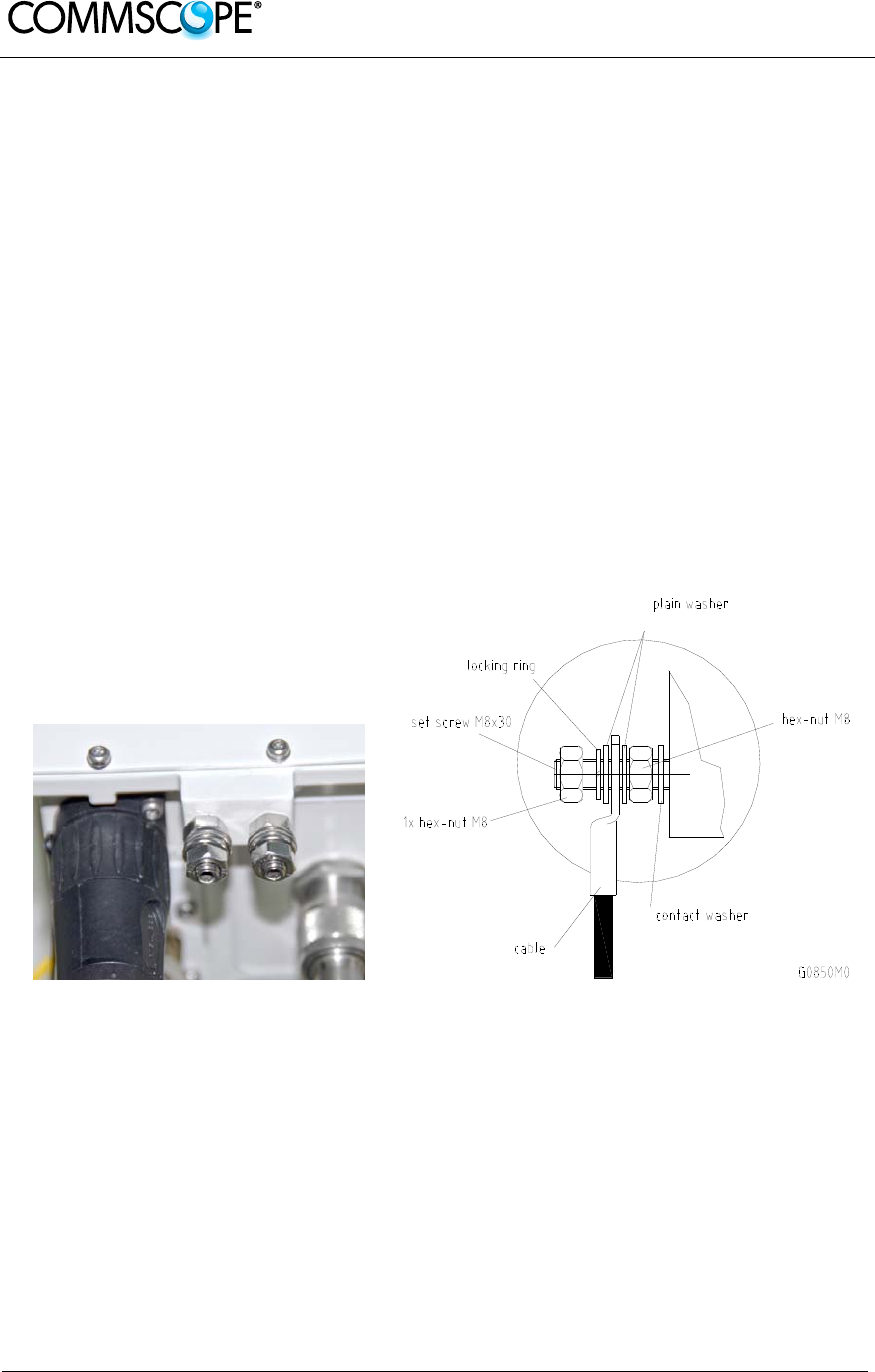
2.1.5.2. Grounding (Earthing)
The RU must be grounded (earthed).
1. Connect an earth-bonding cable to the grounding bolt(s) connection provided on
the outside of the remote unit (near the Mains connector) as shown in Fehler!
Verweisquelle konnte nicht gefunden werden.. Do not use the grounding
connection to connect external devices.
Figure 2-10 Grounding bolts Figure 2-11 Grounding bolt, schematic view
2. After loosening the hex nut, connect the earth-bonding cable between the two
washers as illustrated in the figures above.
3. Then, fasten all parts again by tightening the hex nut.
4. Connect the other end of the ground wire to a suitable permanent ground
following local electrical code practices.
User’s Manual for ION-B Systems
Page 23
2.1.5.3. Mains Power Connection
Before connecting electrical power to the units, the system must be grounded
(earthed) as described in the previous chapter.
The Mains power must be connected to the Mains connector of the unit for operation
of the RU. A power cable is delivered with each RU. The type of power cable
delivered is dependent on the type of power supply in the RU.
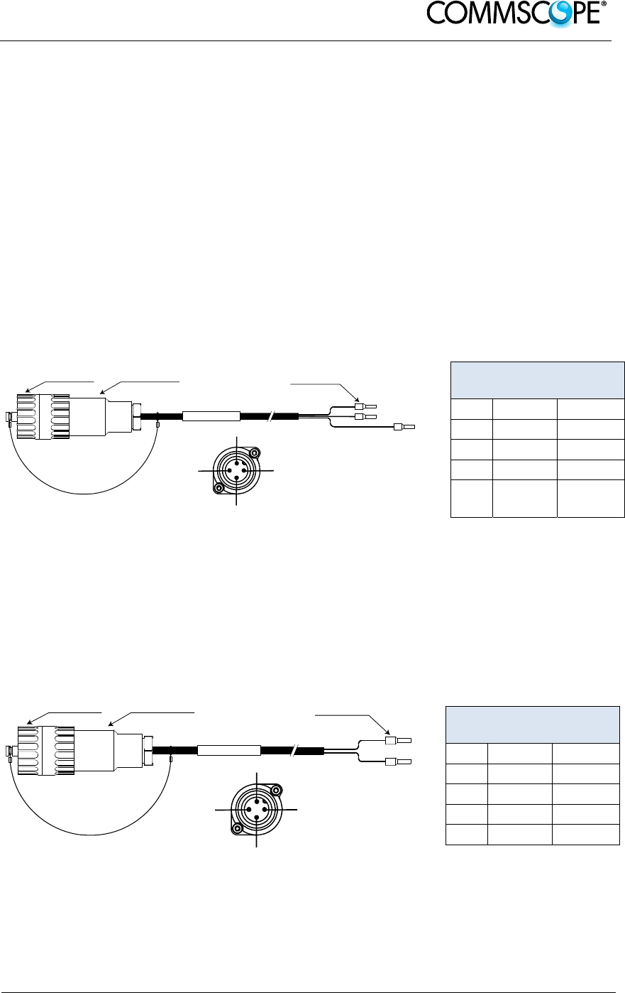
The AC power cable is a 3.2 m (10.5 ft) 16 AWG cable with a 4-pin Amphenol C016
series plug on one end to connect to the RU Mains connector. The other end of the
cable is un-terminated with 3 end splices to connect to the AC power source. A 10 m
(33.7 ft) AC power cable is also available as an option. The AC power cable is shown
in Fehler! Verweisquelle konnte nicht gefunden werden..
blue
A
mphenol 4-Pin
female connector
Protective Cap 3x end splice
brown
yellow / green
B0400A4A
RU Mains
Connector
4
3
2
1
4-Pin Amphenol C016
Series
Pin Name Color
1 Phase Brown
2 Neutral Blue
3 n.c. n.c
4 Ground Yellow /
Green
Figure 2-12 AC power cable Table 3 AC power cable
The standard DC power cable is a 3.2 m (10.5 ft) 13 AWG cable with a 4-pin
Amphenol C016 series plug on one end to connect to the RU Mains connector. The
other end of the cable is un-terminated with 2 end splices to connect to the -48 Vdc
power source. The standard DC power cable is shown in Fehler! Verweisquelle
konnte nicht gefunden werden..
black
Amphenol 4-Pin
female connector
Protective Cap 2x end splice
red
B0400A5A
RU Mains
Connector
4
3
2
1
4-Pin Amphenol C016
Series
Pin Name Color
1 n.c n.c
2 –48V Black
3 0V Red
4 n.c. n.c
Figure 2-13 DC power cable Table 4 DC power cable
User’s Manual for ION-B Systems
Page 24 Manual TFAH-
ES70_80_50.doc
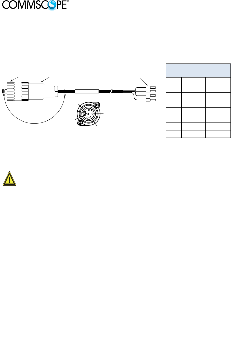
The Vdc/100 power cable is available for locations where the power drawn on each
cable must be limited to a maximum of 100 VA. This cable is a 3.2 m (10.5 ft) 16
AWG cable with a 7-pin Amphenol C016 series plug on one end to connect to the RU
Mains connector. The other end of the cable is un-terminated with 4 end splices to
connect to the -48 Vdc power source.
1
2
4
5
7
Amphenol 7-Pin
female connector
Protective Cap 4x end splice
B0400A6
A
RU Mains
Connector
7-Pin Amphenol C016
Series
Pin Name Color
1 0V White
2 –48V Black
3 n.c. -
4 0V Red
5 –48V Green
6 n.c -
7 n.c -
Figure 2-14 Vdc/100 power cable Table 5 Vdc/100 power
cable
For the AC power supply connection, a minimum cross section of 1.5
mm2 is required and for the DC power supply connection, a minimum
cross section of 2.5 mm2 is required. Each wire must observe the
applicable national regulations regarding loop impedance, voltage drop,
and methods of installation. Make sure to connect the correct voltage to
the unit.
Note: Do not connect or disconnect the power cable at the mains
connector while power is on. Turn off mains* power before
connecting the power cable at the remote unit, then, engage mains
power again.
* Mains power must be interruptible with an external mains breaker. For the
mains breaker, observe the following recommendation:
120 Volt / 20 Amp max. or 240 Volt / 16 Amp, single-phase, 50 / 60 Hz AC
service is needed, i.e. the external AC breaker should be 20 Amps max. for
120-Volt service or 16 Amps for 240-Volt service.
For the DC power supply, observe the local regulations of the DC service
provider.
User’s Manual for ION-B Systems
Page 25
Use the following method to install and connect the Mains power to the RU:
1. Locate the Mains power cable that was delivered with the RU.
2. Locate or install a suitable power junction box or receptacle near the RU and
route the power cable from the power source to the RU. Do not connect the
cable to the RU’s Mains connector at this time. The power source must be
interruptible.
3. The Mains cable must be properly secured observing local regulations and
electrical codes. Be sure to allow enough slack in the cable at the RU to plug
or unplug the cable into the Mains connector of the RU.
4. Wire the power cable to the junction box or receptacle. Refer to the color code
and pin numbers shown in Fehler! Verweisquelle konnte nicht gefunden
werden. (AC cable), Fehler! Verweisquelle konnte nicht gefunden werden.
(DC cable), or Fehler! Verweisquelle konnte nicht gefunden werden.
(Vdc/100 cable) depending on the type of power supply used by the RU.
5. With the cable’s Mains plug disconnected from the RU, turn the circuit breaker
on, unscrew the plug’s protective cover, and carefully test the plug with a
voltmeter to ensure that the voltage and polarity are correct.
6. Once the testing has been completed, turn off the circuit breaker.
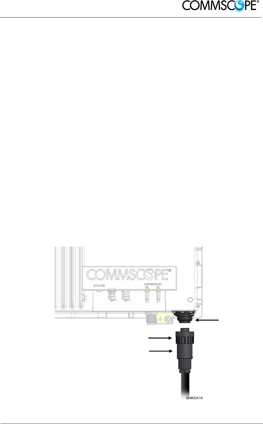
7. Unscrew the protective cover from the Mains connector of the RU.
8. Insert the plug into the Mains connector (Fehler! Verweisquelle konnte nicht
gefunden werden.) and tighten the clamping ring until it is hand tight. Do not
over-tighten the clamping ring.
Figure 2-15 Connect Mains plug
Clamping ring
Mains plug
Mains
connecto
r
User’s Manual for ION-B Systems
Page 26 Manual TFAH-
ES70_80_50.doc
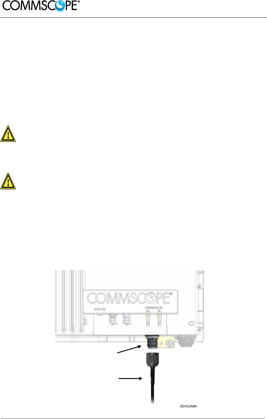
2.1.5.4. Antenna Connection
The Remote Unit has one N-type antenna connector(s) (Fehler! Verweisquelle
konnte nicht gefunden werden.). For mounting the cable connector, it is
recommended to refer to the corresponding documentation of the connector
manufacturer. The bending radius of the antenna cables must remain within the
given specifications.
The selection of cable and antenna is an important consideration. On the one hand, a
cable with higher loss is less expensive but, on the other hand, it impairs
performance.
Use an appropriate torque wrench for the coupling torque of N-type
connectors (2 N-m / 1.5 lb/ft), with 13/16 in opening to tighten the N-type
antenna connectors. For example, use torque wrench of item no. 244379
available from the CommScope e-catalog. Do NOT use your hands or any
other tool (e.g. a pair of pliers)! This might cause damage to the
connector and lead to a malfunction of the Remote Unit.
To minimize passive inter-modulation (PIM) distortion, attention must be
paid to the physical condition of the connector junctions. Do not use
connectors that show signs of corrosion on the metal surface. Prevent
the ingress of water into the connector. Attach and torque the
connectors properly.
1. Route the antenna cable from the antenna or splitter to the base of the RU.
2. Cut the cable to length and terminate the cable with an N-type male connector.
3. Remove the red plastic protective cover from the N-type female connector.
4. Using an appropriate torque wrench, connect the cable to the antenna port of
the RU.
N-type antenna connector
Antenna cable

User’s Manual for ION-B Systems
Page 27
Figure 2-16 N-type antenna connection

User’s Manual for ION-B Systems
Page 28 Manual TFAH-
ES70_80_50.doc
2.1.5.5. Alarm Ports
The Alarm port provides alarm contacts that are used to report alarms generated by
the RU to external equipment. The connector is a 5-pin Binder 712 series connector.
51
B0400AZA
5-Pin Binder 712
Series
Pin Assignment
1 EXT1_Alarm
2 EXT1_GND
3 n.c.
4 EXT2_Alarm
5 EXT_GND
Figure 2-17 Alarm Connector Table 6 Alarm Connector

User’s Manual for ION-B Systems
Page 29
2.2. LOW POWER RU OPTICAL INSTALLATION
2.2.1. Optical-Fiber-Cable Connection - Rules
Main optical system parameters:
Fiber:
Single mode fiber, type is 9.5/125 µm
Fiber-cable connectors LC/APC
ION-U system:
The pigtails for the connection between Master Unit and Remote Unit must
have a sufficient length. Protection for the optical fibers must be provided
where the fibers feed into the units.
The system attenuation of the optical fibers, including the connectors, must
not exceed 5 dB.
System attenuation and attenuation of optical components must be determined. This
can be achieved by measuring attenuation and reflection with an appropriate
measuring instrument. For pigtails, a total value of < 0.4 dB (measured to a reference
plug) can be assumed due to the dead zone of the reflectometer. These
measurements must be made with a sufficient length of optical fiber, at the input and
output of the device which has to be measured.
Fiber-System Installation:
Fiber-cable connectors have to be of the same type (LC/APC) as the connectors
used for the unit. The fiber-optic cables are connected to the optical transceiver.
Angled connectors are not compatible with straight optical connectors;
non-compatibility of connectors will result in permanent damage to
both connectors.
Before connecting the fiber cables, follow the procedure below to ensure optimized
performance. It is important for these procedures to be carried out with care:
Remove fiber-optic protective caps just before making the fiber connections.
Do not leave any LC/APC connectors open as they may attract dirt. Unused
optical connectors must always be covered by their caps.
Do not bend the fiber-optic cable in a tight radius (< 5 cm) as this may cause
damage to the cable and interrupt transmission.

User’s Manual for ION-B Systems
Page 30 Manual TFAH-
ES70_80_50.doc
Using high-grade alcohol and lint-free cotton cleaning swabs, clean the end of
the fiber-optic cable that will be inserted in the optical connectors on the donor
interface box. Use a fiber end-face inspection tool to scan both, the class fiber
and its surrounding area.
Check for dirt on the cladding, chips/pits, dirt on the ferrule, and scratches.
Connect the fiber-optic cables by inserting the cable end into the laser
receptacle.
Do not use any index-matching gels or fluids of any kind in these connectors.
Gels are intended for laboratory use and attract dirt in the field.
Note: Care should be taken when connecting and disconnecting fiber-
optic cables - use the connector housing to plug or unplug a fiber.
Scratches and dust significantly affect system performance and
may permanently damage the connector. Always use protective
caps on fiber-optic connectors not in use.
Cleaning Procedure for Fiber-Optical Components:
Any contamination in the fiber connection results in additional optical transmission
loss which could cause whole system failure. It is thus recommended that every fiber
connector be inspected and cleaned prior to mating.
The goal is to eliminate any dust or contamination and to provide a clean
environment for the fiber-optic connection.
When you clean fiber components, always complete the following steps carefully:
1. Turn off the ION-U system (laser sources) before you inspect fiber connectors.
Never look into a fiber while the system lasers are on!
2. Check the connectors or adapters with a fiberscope before cleaning.
3. If the connector is dirty, clean it with a lint-free wipe (dry cleaning).
4. Inspect the connector.
5. If the connector is still dirty, repeat the dry cleaning technique.
6. Inspect the connector.
7. If the connector is still dirty, clean it with 99% isopropyl alcohol (wet cleaning)
followed immediately with a dry clean in order to ensure no residue is left on
the surface.
8. Repeat steps 5 through 7 until surface is clean.
Note: For a more detailed description, please refer to:
http://www.cisco.com/en/US/tech/tk482/tk876/technologies_white_paper09186
a0080254eba.shtml
User’s Manual for ION-B Systems
Page 31
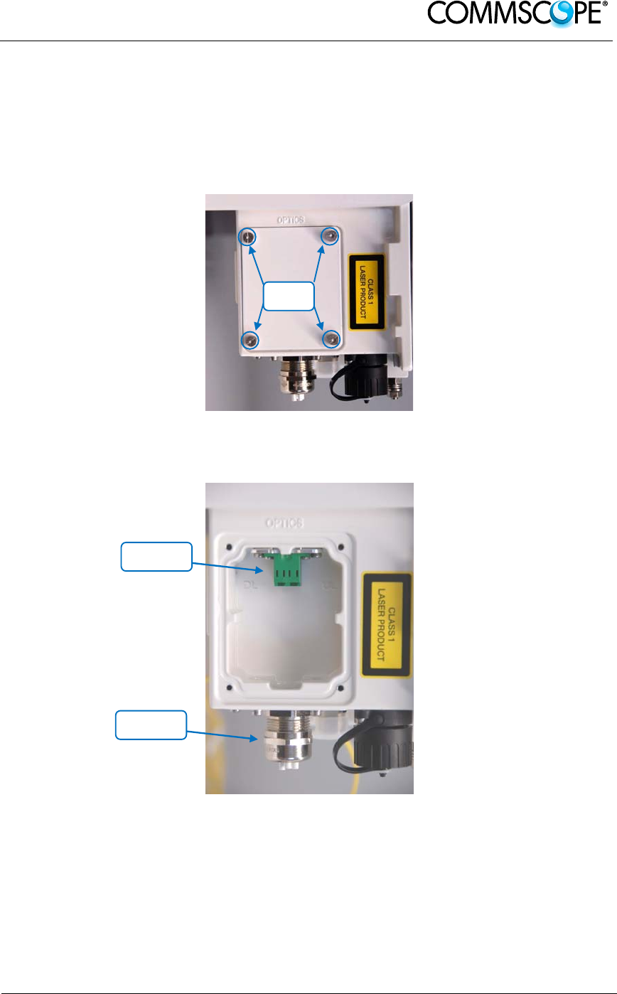
2.2.2. Optical cable installation
1. Locate the Optics connector cover on the lower right side of the RU. Loosen
the four cover screws, remove the cover, and set it aside. Removing this cover
allows access to the UP and DL optical connectors.
Figure 2-18 Remove optics cover
2. Remove the sealing nut from the optical cable gland at the bottom of the RU.
Figure 2-19 Remove sealing nut
Sealing
nut
Cover
Screws
Optical
connectors
User’s Manual for ION-B Systems
Page 32 Manual TFAH-
ES70_80_50.doc
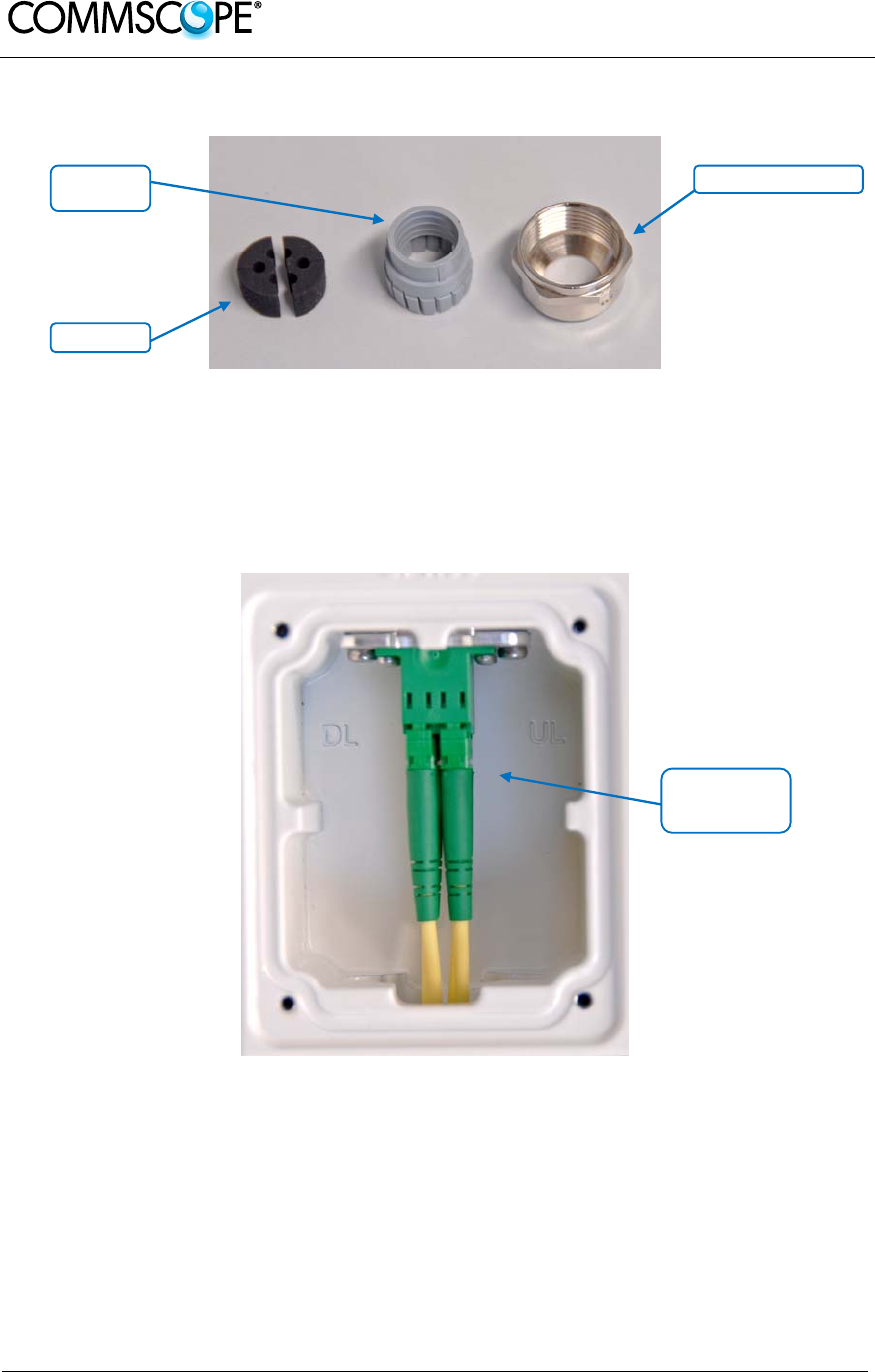
3. Remove the split-seal and clamp jacket.
Figure 2-20 Split-seal and clamp jacket
4. Insert the optical cables through the sealing nut and the clamp jacket.
5. Then insert the optical cables through the opening in the cabinet.
6. Connect the optical cables to the proper UL and DL LC/APC connectors.
Figure 2-21 Optical cables connected
Split-seal
Sealing nut
Clamp
jacket
Connect
LC/APC optical
cables
User’s Manual for ION-B Systems
Page 33
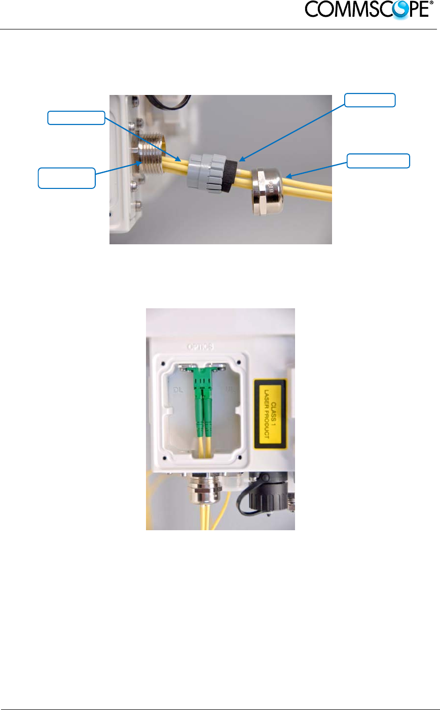
7. Separate the two halves of the split-seal. Place one cable into the hole and the
other in the groove of each half of the split-seal. Insert the spit seal into the
clamp jacket.
Figure 2-22 Place cables into split-seal
8. Insert the clamp jacket with split seal to the connector socket and fasten them
with the sealing nut.
Figure 2-23 Optical cable installed
9. Replace the optics metal cover and tighten the four screws that were
loosened in step 1.
Split-seal
Clamp jacket
Sealing nut
Connector
socket
User’s Manual for ION-B Systems
Page 34 Manual TFAH-
ES70_80_50.doc
2.2.3. RU Power Supply Replacement
The power supply for the RU is a field replaceable module. The type of power supply
used by the RU (AC, DC, or Vdc/100) is dependent on the model number of the RU.
Before starting any maintenance on the RU, read the health and safety
warnings in chapter 4.2.1.
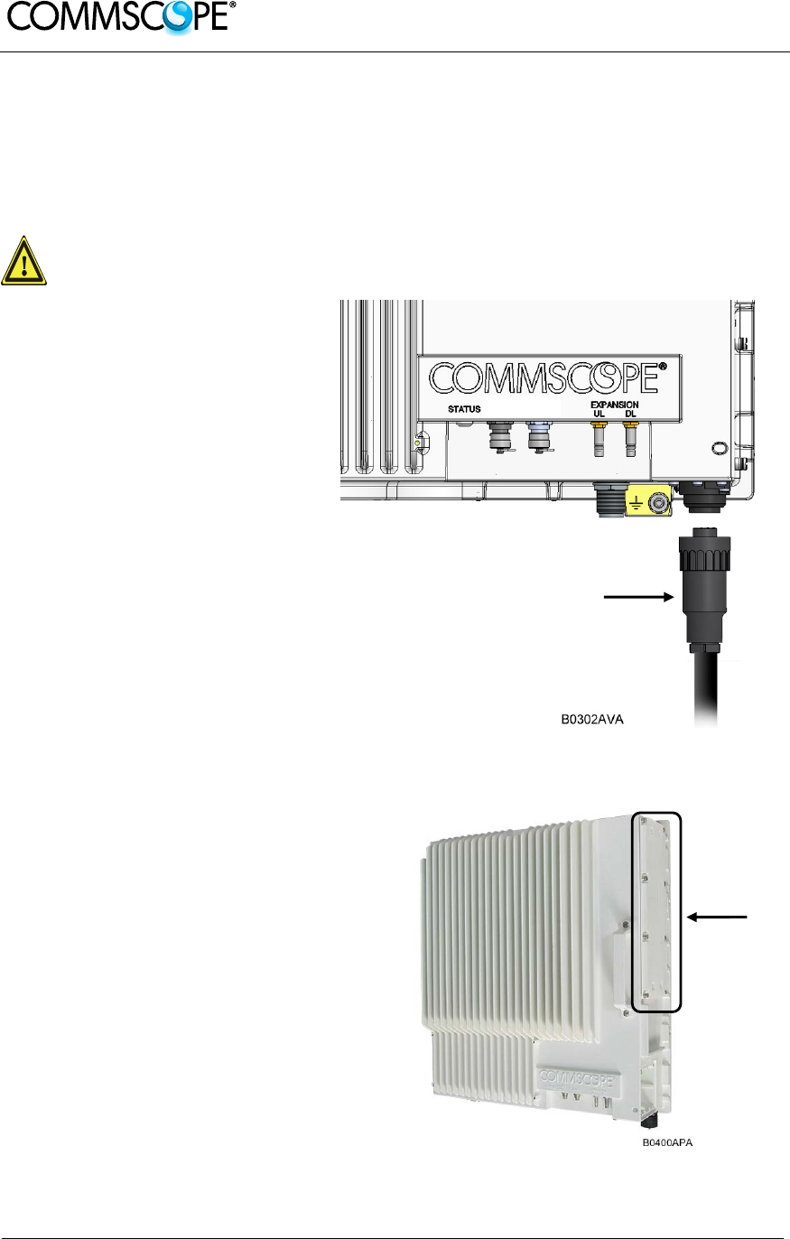
1. Switch off the circuit breaker
supplying power to the RU.
2. Once you have confirmed that
the power has been shutdown,
remove Mains power
connector from the RU.
Figure 2-24 Disconnect Mains power
3. Locate the power supply on
the right side of the Remote
Unit.
Figure 2-25 RU power supply location
Mains plug
Power
supply
User’s Manual for ION-B Systems
Page 35
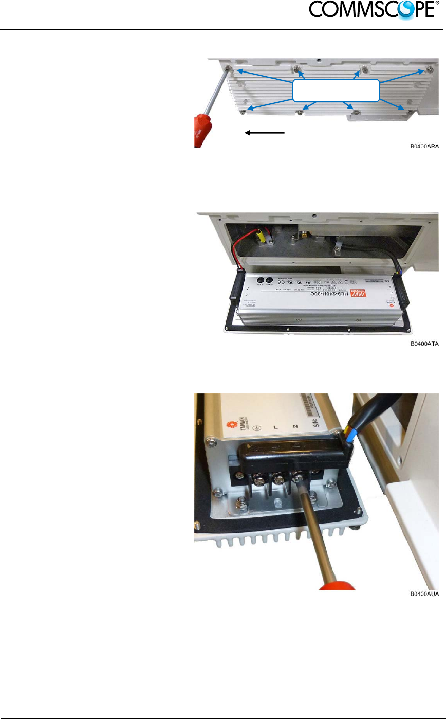
4. Use a #2 Phillips head or
slotted screwdriver to loosen
the 8 universal slot/Phillips
captive power supply screws
and carefully remove the
supply. The weight of the
power supply must be
supported as you loosen the
screws to prevent damage to
the supply.
Figure 2-26 8 RU power supply screws
5. Carefully remove the power
supply from the unit. Do not
attempt to support the weight
of the supply with the attached
input and output cables.
Figure 2-27 RU power supply with cables
6. Locate the input cable
connector for the power
supply on the right side of the
supply.
7. Loosen the 3 Phillips head
terminal screws and remove
the connector.
Figure 2-28 RU power supply input cable
Mains
connecto
r
Loosen 8 universal
slot/Phillips screws
User’s Manual for ION-B Systems
Page 36 Manual TFAH-
ES70_80_50.doc
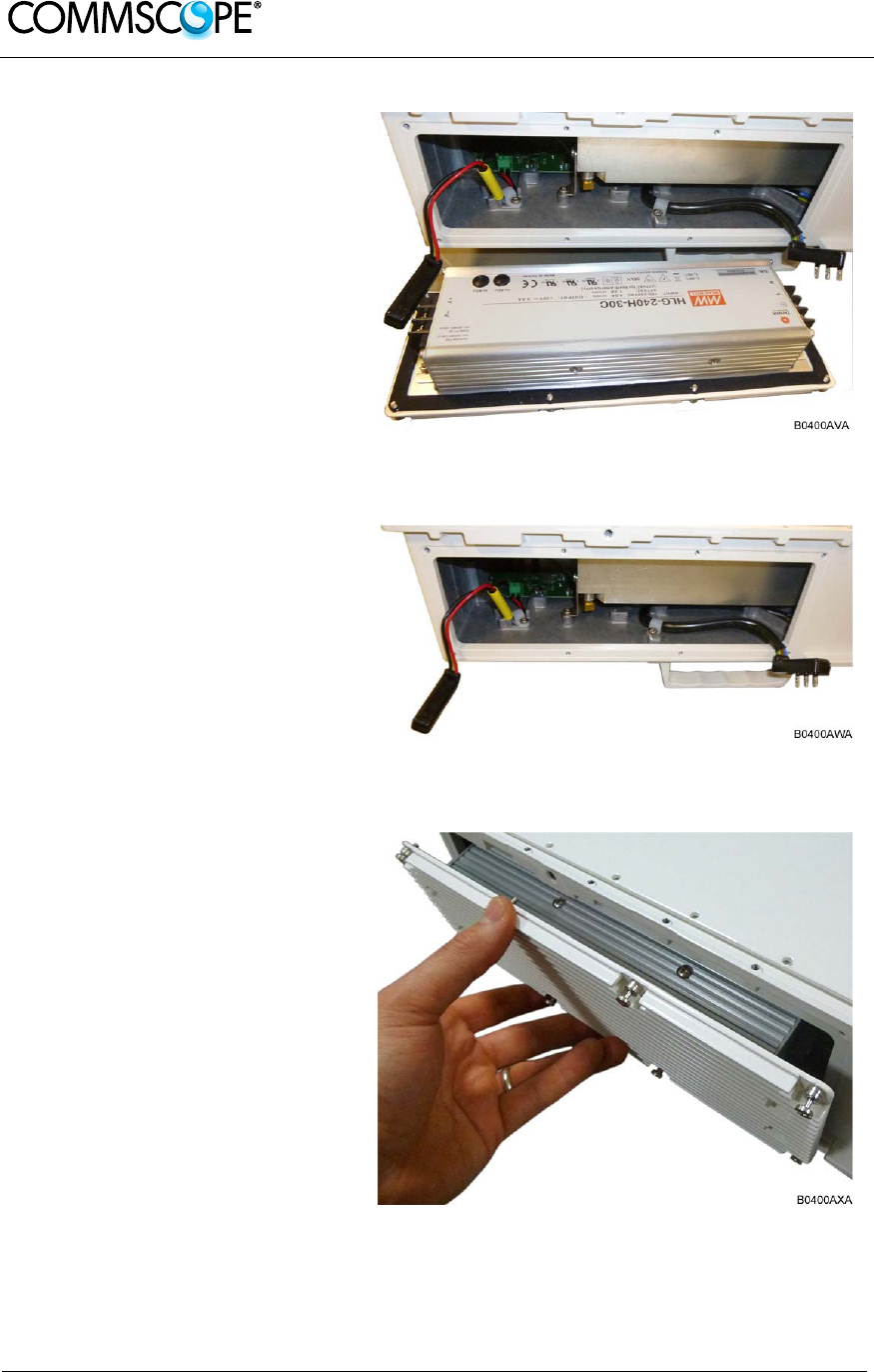
8. Locate the output connector
for the power supply on the
left side of the supply.
9. Loosen the 2 Phillips head
screws and remove the output
connector.
Figure 2-29 RU power supply output cable
10. Remove the defective supply.
Figure 2-30 RU with power supply removed
11. Replace the defective power
supply with the new power
supply.
It is very important to confirm
that the replacement supply is
the same type as the original
supply. The AC, DC, and
Vdc/100 supplies are not
interchangeable.
12. Reconnect the input and
output connectors, and tighten
the associated terminal
screws.
Figure 2-31 RU with replacement power supply
User’s Manual for ION-B Systems
Page 37
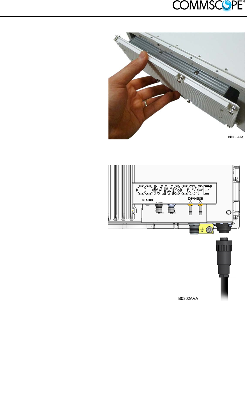
13. Insert the power supply into
the RU carefully to avoid
damaging any cables. The
supply must be supported until
the 8 universal slot/Phillips
captive power supply screws
have been tightened.
14. Tighten the 8 universal
slot/Phillips captive power
supply screws.
Figure 2-32 RU insert power supply
15. Reconnect the Mains power
plug.
16. Switch on the breaker and
check the RU for proper
operation.
Figure 2-33 Reconnect Mains power

User’s Manual for ION-B Systems
Page 38 Manual TFAH-
ES70_80_50.doc
3. TECHNICAL SUPPORT
3.1. CONTACT ADDRESSES
The ION-B is developed by:
Commscope Italy Srl
Via Pier De Crescenzi 40
48018 Faenza, Italy
Tel: +39.0546.697111
Fax: +39.0546.682768
For further information about the product, please write to:
IONB.support@andrew.com

User’s Manual for ION-B Systems
Page 39
3.2. RETURNING EQUIPMENT
Before returning any equipment to the manufacturer for repairation or replacement, the
customer should give prior notice to the manufacturer and ask for the ‘Return Material
Authorisation’ (RMA request).
RMA REQUEST FORM
Company name
Address
Contact person
Invoice number
Delivery note
№ of pieces
Model 1)
Serial Number 1)
Lot1)
Year1)
Description of the failure/ defect
1) Please refer to the serial label
Upon accepting your RMA request, the manufacturer will assign you a unique RMA
code. You will therefore be able to return the equipment to the manufacturer. Please
remember that:
each piece of equipment must be packaged with care before shipment;
a copy of the RMA request form must be included with the returning
equipment, with clear indication of the RMA code you received from the
manufacturer.
The returned pieces are able to be repaired (where possible) or replaced (when no
repairations can be carried out). These operations are performed under warranty
(please see the warranty conditions specified in the sales contract) or out-of-
warranty. In the latter case, we will send you a bill for equipment repairation or
replacement.
When returning the repaired or replaced equipment, the manufacturer will issue a
check report, which will be included in the packaging together with the returned
pieces. The customer will be informed of any corrective actions suggested for quality
assurance.