Andrew Wireless System U7885L17E19P ION-U Remote Unit for cellular systems User Manual
Andrew Wireless System ION-U Remote Unit for cellular systems
Contents
- 1. Installation Instruction
- 2. user manual
user manual
ION®-U
ION-U L 7/80-85/17(E)P/19P
Manual
MF0200A5C

Page 2 MF0200A5C_ION-U_L_7_80-85_17EP_19P.docx Manual for ION
®
-U
DISCLAIMER:
This document has been developed by CommScope, and is intended for the use of its
customers and customer support personnel. The information in this document is subject to
change without notice. While every effort has been made to eliminate errors, CommScope
disclaims liability for any difficulties arising from the interpretation of the information
contained herein. The information contained herein does not claim to cover all details or
variations in equipment, nor to provide for every possible incident to be met in connection
with installation, operation, or maintenance. This document describes the performance of the
product under the defined operational conditions and does not cover the performance under
adverse or disturbed conditions. Should further information be desired, or should particular
problems arise which are not covered sufficiently for the purchaser’s purposes, contact
CommScope.
CommScope reserves the right to change all hardware and software characteristics without
notice.
COPYRIGHT:
© Copyright 2016 CommScope Inc. All Rights Reserved.
This document is protected by copyright. No part of this document may be reproduced,
stored in a retrieval system, or transmitted, in any form or by any means, electronic,
mechanical photocopying, recording, or otherwise without the prior written permission of
CommScope.
TRADEMARKS
All trademarks identified by ® or ™ are registered trademarks or trademarks, respectively, of
CommScope. Names of products mentioned herein are used for identification purposes only
and may be trademarks and / or registered trademarks of their respective companies.
Andrew Wireless Systems GmbH, 18-April-2016

Table of Contents
MF0200A5C_ION-U_L_7_80-85_17EP_19P.docx Manual for ION
®
-U Page 3
TABLE OF CONTENTS
1.
GENERAL 7
1.1.USED ABBREVIATIONS 7
1.2.HEALTH AND SAFETY 8
1.3.PROPERTY DAMAGE WARNINGS 8
1.4.COMPLIANCE 9
1.5.ABOUT COMMSCOPE 13
1.6.INTERNATIONAL CONTACT ADDRESSES FOR CUSTOMER SUPPORT 14
2.
INTRODUCTION 16
2.1.PURPOSE 16
2.2.ION-U LOW POWER REMOTE UNITS 16
3.
FUNCTIONAL DESCRIPTION 17
3.1.GENERAL 17
3.2.SISO AND MIMO OPERATION 18
3.3.ION-U LOW POWER RU PORTS 19
4.
COMMISSIONING 21
4.1.LOW POWER RU MECHANICAL INSTALLATION 21
4.1.1.Health and Safety for mechanical installation 21
4.1.2.Property Damage Warnings for mechanical installation 21
4.1.3.Mounting bracket 22
4.1.3.1.Mount to a wall 22
4.1.3.2.Mount to a pole 23
4.1.4.Threaded pins 25
4.1.5.Wall mounting procedure – Single Unit (SISO) 26
4.1.6.Wall mounting procedure – Dual Units (MIMO) 28
4.1.7.Pole mounting procedure – SISO and MIMO 32
4.2.LOW POWER RU ELECTRICAL INSTALLATION 33
4.2.1.Health and Safety for electrical installation 33
4.2.2.Property Damage Warnings for electrical installation 33
4.2.3.Connections 35
4.2.4.Grounding (Earthing) 36
4.2.5.Mains power connection 37
4.2.6.Antenna connection 39
4.2.6.1.Cleaning procedure for RF cable connectors 40
4.2.6.2.Antenna cable connector assembly 44

Table of Contents
Page 4 MF0200A5C_ION-U_L_7_80-85_17EP_19P.docx Manual for ION
®
-U
4.2.7.Coupling probe 45
4.2.8.Expansion ports connections 46
4.2.9.Alarm port 46
4.2.10.Pwr/Ctrl port 47
4.2.11.Control connector RS-232 - Local Interface 47
4.3.LOW POWER RU OPTICAL INSTALLATION 48
4.3.1.Optical-fiber-cable connection - rules 48
4.3.2.Optical cable installation 50
4.4.ACCESSORY EQUIPMENT INSTALLATION – SPLICE BOX 53
4.4.1.SISO installation 54
4.4.2.MIMO installation 55
4.5.LOW POWER RU ALARMS 56
4.5.1.Bite and alarms 56
4.5.2.Handling of alarms 56
4.5.3.Status LED alarms 57
4.6.EXTERNAL ALARM INPUTS 58
4.7.TROUBLESHOOTING 59
5.
LOW POWER RU MAINTENANCE 59
5.1.GENERAL 59
5.2.RU POWER SUPPLY REPLACEMENT 60
6.
APPENDIX 64
6.1.ILLUSTRATIONS 64
6.2.SPECIFICATIONS 66
6.3.SPARE PARTS 66
7.
LIST OF CHANGES 66
8.
INDEX 67

Figures and Tables
MF0200A5C_ION-U_L_7_80-85_17EP_19P.docx Manual for ION
®
-U Page 5
FIGURES AND TABLES
figure 3-2 Remote Unit, SISO ..................................................................................... 18
figure 3-3 Remote Unit, MIMO two units paired ......................................................... 18
figure 3-4 One RU one EU one antenna .................................................................... 18
figure 3-5 Two RUs one EU two antennas ................................................................. 19
figure 3-6 RU connectors and Status LED ................................................................. 19
figure 4-1 Mounting bracket ........................................................................................ 22
figure 4-2 Pole-mounting kit 4" to 18" ......................................................................... 24
figure 4-3 Pole-mounting kit 40” ................................................................................. 24
figure 4-4 RU threaded pin power supply side ........................................................... 25
figure 4-5 RU threaded pin narrow side ..................................................................... 25
figure 4-6 Place RU onto wall mounting bracket – single mount ............................... 26
figure 4-7 Install M6x12 screws and washers for single mount ................................. 27
figure 4-8 Attach M6 nut to threaded pins for single mount ....................................... 27
figure 4-9 Completed SISO RU mount ....................................................................... 28
figure 4-10 1
st
RU placed on wall mounting bracket - MIMO ..................................... 29
figure 4-11 Install M6x12 screws and washers .......................................................... 29
figure 4-12 Attach M6 nut to threaded pins ................................................................ 30
figure 4-13 2
nd
RU on wall mounting bracket ............................................................. 30
figure 4-14 Install M6x12 screws and washers 2
nd
RU .............................................. 31
figure 4-15 Attach M6 nut to threaded pins for 2
nd
RU ............................................... 31
figure 4-16 Completed MIMO RU mount .................................................................... 32
figure 4-17 Grounding bolts ........................................................................................ 36
figure 4-18 Grounding bolt, schematic view ............................................................... 36
figure 4-19 AC power cable ........................................................................................ 37
figure 4-20 DC power cable ........................................................................................ 37
figure 4-21 Vdc/100 power cable ................................................................................ 38
figure 4-22 Connect mains plug ................................................................................. 39
figure 4-23 Antenna connection ................................................................................. 45
figure 4-24 Expansion ports ........................................................................................ 46
figure 4-25 Alarm connector ....................................................................................... 46
figure 4-26 Pwr/Ctrl connector .................................................................................... 47
figure 4-27 RS-232 connector .................................................................................... 47
figure 4-28 Remove optics cover ................................................................................ 50
figure 4-29 Remove sealing nut ................................................................................. 51
figure 4-30 Split-seal and clamp jacket ...................................................................... 51
figure 4-31 Optical cables connected ......................................................................... 52
figure 4-32 Place cables into split-seal ....................................................................... 52
figure 4-33 Optical cable installed .............................................................................. 53
figure 4-34 Alarm triggering ........................................................................................ 56
figure 5-1 Disconnect mains power ............................................................................ 60
figure 5-2 RU power supply location .......................................................................... 61
figure 5-3 8 RU power supply screws ......................................................................... 61
figure 5-4 RU power supply with cables ..................................................................... 61
figure 5-5 RU power supply input cable ..................................................................... 62
figure 5-6 RU power supply output cable ................................................................... 62
figure 5-7 RU with power supply removed ................................................................. 62
figure 5-8 RU insert power supply .............................................................................. 63

Figures and Tables
Page 6 MF0200A5C_ION-U_L_7_80-85_17EP_19P.docx Manual for ION
®
-U
figure 5-9 Reconnect mains power ............................................................................. 63
figure 6-1 ION-U Low Power RU mounting bracket ................................................... 64
figure 6-2 ION-U Low Power Unit dimensions ........................................................... 64
figure 6-3 Installation drawing of ION-U L Unit SISO ................................................. 65
figure 6-4 Installation drawing of ION-U L Unit MIMO ................................................ 65
table 1-1 List of international contact addresses ........................................................ 15
table 4-1 Specified torques ......................................................................................... 22
table 4-2 ION-U Low Power RU connectors - description .......................................... 35
table 4-3 AC power cable ........................................................................................... 37
table 4-4 DC power cable ........................................................................................... 37
table 4-5 Vdc/100 power cable ................................................................................... 38
table 4-6 Alarm connector .......................................................................................... 46
table 4-7 Pwr/Ctrl connector ....................................................................................... 47
table 4-8 RS-232 connector, pin assignment ............................................................. 47
table 4-9 Status LED alarms ....................................................................................... 58

1. General
MF0200A5C_ION-U_L_7_80-85_17EP_19P.docx Manual for ION
®
-U Page 7
1. General
1.1. Used Abbreviations
AC/DC Alternating current / Direct Current
ALC Automatic Level Control
BITE Built-In Test Equipment
BTS Base Transceiver Station
CDMA Code Division Multiple Access
CE "Conformité Européenne" ("European Conformity")
CPD Channel Power Detection
DL Downlink
DoC Declaration of Conformity
EP Extension Port
ESD Electrostatic Discharge
EU Extension Unit
GSM Global System for Mobile Communication
GND Ground (Earth)
GUI Graphical User Interface
ICP3 Intercept Point 3rd order
ID No Identification Number
ION Intelligent Optical Network
LED Light Emitting Diode
LMT Local Maintenance Terminal
LTE Long Term Evolution
MIMO Multiple Input Multiple Output
MS Mobile Station
MU Main Unit
NF Noise Figure
OMC Operations and Maintenance Center
OTRx Optical Transceiver = SRMU (Subrack Master Unit)
PDU Power Distribution Unit
PIM Passive Intermodulation
Pin Input power
Pout Output power
PSU Power Supply Unit
Rev Revision
RF Radio Frequency
RU Remote Unit
RX Receiver
SISO Single Input Single Output
SNMP Simple Network Management Protocol
TX Transmitter
UL Uplink
UMTS Universal Mobile Telecommunication System
UPS Uninterruptible Power Supply
VSWR Voltage Standing Wave Ratio
WCDMA Wideband Code Division Multiple Access
WDM Wavelength Division Multiplex
XML Extensible Markup Language
1. General
Page 8 MF0200A5C_ION-U_L_7_80-85_17EP_19P.docx Manual for ION
®
-U
1.2. Health and Safety
1. Danger: Electrical hazard. Danger of death or fatal injury from electrical
current. Obey all general and regional installation and safety regulations
relating to work on high voltage installations, as well as regulations
covering correct use of tools and personal protective equipment.
2. Danger: Electrical hazard. Danger of death or fatal injury from electrical
current inside the unit in operation. Before opening the unit, disconnect
mains power.
3. Caution: Laser radiation. Risk of eye injury in operation. Do not stare into the
beam; do not view it directly or with optical instruments.
4. Caution: High frequency radiation in operation. Risk of health hazards associated
with radiation from the unit’s inner conductor of the antenna port(s). Disconnect
mains before connecting or replacing antenna cables.
5. Caution: High frequency radiation in operation. Risk of health hazards associated
with radiation from the antenna(s) connected to the unit. Implement prevention
measures to avoid the possibility of close proximity to the antenna(s) while in
operation.
1.3. Property Damage Warnings
1. Attention: Due to power dissipation, the Remote Unit may reach a very high
temperature. Do not operate this equipment on or close to flammable materials.
Use caution when servicing the unit.
2. Attention: Only authorized and trained personnel are allowed to open the unit
and get access to the inside.
3. Notice: Although the unit is internally protected against overvoltage, it is strongly
recommended to ground (earth) the antenna cables close to the antenna
connectors of the unit for protection against atmospheric discharge. In areas with
strong lightning, it is strongly recommended to install additional lightning
protection.
4. Notice: ESD precautions must be observed. Before commencing maintenance
work, use the available grounding (earthing) system to connect ESD protection
measures.
5. Notice: Only suitably qualified personnel are allowed to work on this unit and only
after becoming familiar with all safety notices, installation, operation and
maintenance procedures contained in this manual.

1. General
MF0200A5C_ION-U_L_7_80-85_17EP_19P.docx Manual for ION
®
-U Page 9
6. Notice: Keep operating instructions within easy reach and make them available
to all users.
7. Notice: Read and obey all the warning labels attached to the unit. Make sure that
all warning labels are kept in a legible condition. Replace any missing or
damaged labels.
8. Notice: Only license holders for the respective frequency range are allowed to
operate this unit.
9. Notice: Make sure the repeater settings are correct for the intended use (refer to
the manufacturer product information) and regulatory requirements are met. Do
not carry out any modifications or fit any spare parts, which are not sold or
recommended by the manufacturer.
1.4. Compliance
1. Notice: For installations which have to comply with European EN50385 exposure
compliance requirements, the following Power Density limits/guidelines (mW/cm²)
according to ICNIRP are valid:
o 0.2 for frequencies from 10 MHz to 400 MHz
o F (MHz) / 2000 for frequencies from 400 MHz to 2 GHz
o 1 for frequencies from 2 GHz to 300 GHz
2. Notice: For installations, which have to comply with FCC RF exposure
requirements, the antenna selection and installation must be completed in a way
to ensure compliance with those FCC requirements. Depending on the RF
frequency, rated output power, antenna gain, and the loss between the repeater
and antenna, the minimum distance D to be maintained between the antenna
location and human beings is calculated according to this formula:
]/[
][
][
2
4
cmmW
mW
cm
PD
P
D
where
P (mW) is the radiated power at the antenna, i.e. the max. rated repeater
output power in addition to the antenna gain minus the loss between the
repeater and the antenna.
PD (mW/cm²) is the allowed Power Density limit acc. to 47 CFR 1.1310 (B)
for general population / uncontrolled exposures which is
o F (MHz) / 1500 for frequencies from 300MHz to 1500MHz
o 1 for frequencies from 1500MHz to 100,000MHz
RF exposure compliance may need to be addressed at the time of licensing, as
required by the responsible FCC Bureau(s), including antenna co-location
requirements of 1.1307(b)(3).

1. General
Page 10 MF0200A5C_ION-U_L_7_80-85_17EP_19P.docx Manual for ION
®
-U
3. Notice: Installation of this equipment is in full responsibility of the installer, who
has also the responsibility, that cables and couplers are calculated into the
maximum gain of the antennas, so that this value, which is filed in the FCC Grant
and can be requested from the FCC data base, is not exceeded. The industrial
boosters are shipped only as a naked booster without any installation devices or
antennas as it needs for professional installation.
4. Notice: For installations which have to comply with FCC/Industry Canada
requirements:
English:
This device complies with FCC Part 15 and Industry Canada license exempt RSS
standard(s). Operation is subject to the following two conditions: (1) this device
may not cause interference, and (2) this device must accept any interference,
including interference that may cause undesired operation of the device.
This device complies with Health Canada’s Safety Code. The installer of this
device should ensure that RF radiation is not emitted in excess of the Health
Canada’s requirement. Information can be obtained at http:
//www.hc-sc.gc.ca/ewh-semt/pubs/radiation/radio_guide-lignes_direct-eng.php.
Changes or modifications not expressly approved by the party responsible for
compliance could void the user’s authority to operate the equipment.
French:
Cet appareil est conforme à FCC Partie15 d’Industrie Canada RSS standard
exempts de licence (s). Son utilisation est soumise à Les deux conditions
suivantes: (1) cet appareil ne peut pas provoquer d’interférences et (2) cet
appareil doit accepter Toute interférence, y compris les interférences qui peuvent
causer un mauvais fonctionnement du dispositif.
Cet appareil est conforme avec Santé Canada Code de sécurité 6. Le
programme d’installation de cet appareil doit s’assurer que les rayonnements RF
n’est pas émis au-delà de I’exigence de Santé Canada. Les informations peuvent
être obtenues:
http://www.hc-sc.gc.ca/ewh-semt/pubs/radiation/radio_guide-lignes_direct-
fra.php
Les changements ou modifications non expressément approuvés par la partie
responsable de la conformité pourraient annuler l'autorité de l'utilisateur à utiliser
cet équipement.
5. Notice: Corresponding local particularities and regulations must be observed. For
national deviations, please refer to the respective documents included in the
manual CD that is delivered with the unit.

1. General
MF0200A5C_ION-U_L_7_80-85_17EP_19P.docx Manual for ION
®
-U Page 11
6. Notice: The unit complies with Overvoltage Category II. It also complies with the
surge requirement according to EN 61000-4-5 (fine protection); however,
installation of an additional medium (via local supply connection) and/or coarse
protection (external surge protection) is recommended depending on the
individual application in order to avoid damage caused by overcurrent.
For Canada and US, components used to reduce the Overvoltage Category shall
comply with the requirements of IEC 61643-series. As an alternative,
components used to reduce the Overvoltage Category may comply with
ANSI/IEEE C62.11, CSA Certification Notice No. 516, CSA C22.2 No. 1, or UL
1449. Suitability of the component for the application shall be determined for the
intended installation.
7. Note: For a Class A digital device or peripheral:
This equipment has been tested and found to comply with the limits for a Class A
digital device, pursuant to part 15 of the FCC Rules. These limits are designed to
provide reasonable protection against harmful interference when the equipment is
operated in a commercial environment. This equipment generates, uses, and can
radiate radio frequency energy and, if not installed and used in accordance with
the instruction manual, may cause harmful interference to radio communications.
Operation of this equipment in a residential area is likely to cause harmful
interference in which case the user will be required to correct the interference at
his own expense.
8. Note: This unit complies with European standard EN60950.
1. General
Page 12 MF0200A5C_ION-U_L_7_80-85_17EP_19P.docx Manual for ION
®
-U
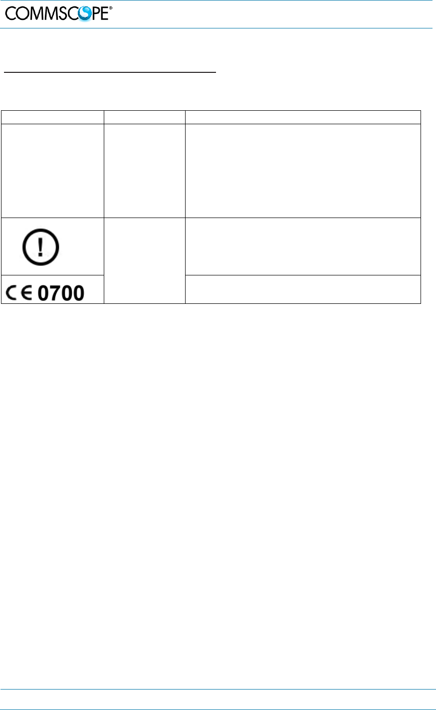
Equipment Symbols Used / Compliance
Please observe the meanings of the following symbols used in our equipment and
the compliance warnings:
Symbol Compliance Meaning / Warning
--- FCC
For industrial (Part 20) signal booster:
WARNING: This is NOT a CONSUMER device. It is
designed for installation by FCC LICENSEES and
QUALIFIED INSTALLERS. You MUST have an FCC
LICENSE or express consent of an FCC Licensee to
operate this device. Unauthorized use may result in
significant forfeiture penalties, including penalties in
excess of $100,000 for each continuing violation.
CE
Alert sign to R&TTE
To be sold exclusively to mobile operators or
authorized installers – no harmonized frequency
bands, operation requires license. Intended use: EU
and EFTA countries
Indicates conformity with the R&TTE directive
1999/5/EC certified by the notified body no. 0700.
Note: The Manufacturer’s rated output power of this equipment is for single carrier
operation. For situations when multiple carrier signals are present, the rating would
have to be reduced by 3.5 dB, especially where the output signal is reradiated and
can cause interference to adjacent band users. This power reduction is to be by
means of input power or gain reduction and not by an attenuator at the output of the
device.

1. General
MF0200A5C_ION-U_L_7_80-85_17EP_19P.docx Manual for ION
®
-U Page 13
1.5. About CommScope
CommScope is the foremost supplier of one-stop, end-to-end radio frequency (RF)
solutions. Part of the CommScope portfolio are complete solutions for wireless
infrastructure from top-of-the-tower base station antennas to cable systems and
cabinets, RF site solutions, signal distribution, and network optimization. For patents
see www.cs-pat.com.
CommScope has global engineering and manufacturing facilities. In addition, it
maintains field engineering offices throughout the world.
Andrew Wireless Systems GmbH based in Buchdorf/ Germany, which is part of
CommScope, is a leading manufacturer of coverage equipment for mobile radio
networks, specializing in high performance, RF and optical repeaters. Our optical
distributed networks and RF repeater systems provide coverage and capacity
solution for wireless networks in both indoor installations and outdoor environments,
e.g. tunnels, subways, in-trains, airport buildings, stadiums, skyscrapers, shopping
malls, hotels and conference rooms.
Andrew Wireless Systems GmbH operates a quality management system in
compliance with the requirements of ISO 9001 and TL 9000. All equipment is
manufactured using highly reliable material. To maintain highest quality of the
products, comprehensive quality monitoring is conducted at all fabrication stages.
Finished products leave the factory only after a thorough final acceptance test,
accompanied by a test certificate guaranteeing optimal operation.
This product meets the requirements of the R&TTE directive and the Declaration of
Conformity (DoC) itself. A current version of the CE DoC is included in this manual
CD delivered *. Any updated version of the DoC is available upon request from the
local sales offices or directly from CommScope via the local Customer Support at
one of the addresses listed in the following chapter.
According to the DoC, our "CE"-marked equipment can be used in all member
states of the European Union.
Note: Exceptions of and national deviations from this intended use may be
possible. To observe corresponding local particularities and
regulations, please refer to the respective documents (also in
national language) which are included in the manual CD delivered.
* In case the Declaration of Conformity (DoC) for the product was not included in the manual CD
delivered, it is available upon request from the local sales offices or directly from CommScope at
one of the addresses listed in the following chapter.
To make the most of this product, we recommend you carefully read the instructions
in this manual and commission the system only according to these instructions.
For technical assistance and support, please also contact the local office or
CommScope directly at one of the addresses listed in the following chapter.
1. General
Page 14 MF0200A5C_ION-U_L_7_80-85_17EP_19P.docx Manual for ION
®
-U
1.6. International Contact Addresses for Customer Support
Canada
A
M
E
R
I
C
A
S
United States
CommScope Canada
A
ndrew LLC, A CommScope Company
Mail 505 Consumers Road, Suite 803
Toronto M2J 4V8, Canada Mail 620 North Greenfield Parkway
Garner, NC 27529, U.S.A.
Phone +1-905-878-3457 (Office)
+1-416-721-5058 (Cell) Phone +1-888-297-6433
Fax +1-905-878-3297 Fax +1-919-329-8950
E-mail wisupport@commscope.com E-mail wisupport@commscope.com
Caribbean & South American Region Caribbean & Central American Region
CommScope Cabos do Brasil Ltda. CommScope Mexico S.A. de C.V.
Mail
CALA Tech Support for Distributed
Coverage & Capacity Solutions (DCCS)
products:
Rua Guaporanga, 49
Praça Seca – Rio de Janeiro – RJ
ZIP: 21320-180, Brazil
Mail
CALA Tech Support for Distributed
Coverage & Capacity Solutions
(DCCS) products:
Av. Insurgentes Sur 688, Piso 6
Col. Del Valle, CP: 03100
Mexico City, Mexico
Phone +1-815-546-7154 (Cell)
+55-15-9104-7722 (Office) Phone +52-55-1346-1900 (Office)
Fax + 55-15-2102-4001 Fax +52-55-1346-1901
E-mail wisupport@commscope.com E-mail wisupport@commscope.com
China, India and Rest of Asia
A
P
A
C
Australia & New Zealand
Andrew International Corporation
A
ndrew Corporation (Australia) Pty Ltd.
Mail
Room 915, 9/F
Chevalier Commercial Centre
8 Wang Hoi Rd
Kowloon Bay, Hong Kong
Mail
Unit 1
153 Barry Road
Campbellfield
VIC 3061, Australia
Phone +852-3106-6100 Phone +613-9300-7969
Fax +852-2751-7800 Fax +613-9357-9110
E-mail wisupport.China@commscope.com E-mail wisupport.Australia@commscope.com
Middle East & North Africa
Africa
&
Middle
East
South Africa
CommScope Solutions International Inc.
(Branch)
A
ndrew Wireless Solutions Africa
(PTY) LTD
Mail
PO Box 48 78 22
Unit 3206, Floor 32,
Jumeirah Business Center 5,
Jumeirah Lakes Towers,
Dubai, United Arab Emirates
Mail
11 Commerce Crescent West
Eastgate, Sandton
PO Box 786117
Sandton 2146
South Africa
Phone +971 4 390 09 80 Phone + 27 11-719-6000
Fax +971 4 390 86 23 Fax + 27 11-444-5393
E-mail wisupport@commscope.com E-mail wisupport@commscope.com
1. General
MF0200A5C_ION-U_L_7_80-85_17EP_19P.docx Manual for ION
®
-U Page 15
United Kingdom
E
U
R
O
P
E
Scandinavia
Andrew Wireless Systems UK Ltd
A
ndrew Norway (AMNW)
Mail
Unit 15, Ilex Building
Mulberry Business Park
Fishponds Road
Wokingham Berkshire
RG41 2GY, England
Mail
P.O. Box 3066
Osloveien 10
Hoenefoss 3501
Norway
Phone +44-1189-366-792 Phone + 47 32-12-3530
Fax +44-1189-366-773 Fax + 47 32-12-3531
E-mail wisupport.uk@commscope.com E-mail wisupport@commscope.com
Germany France
Andrew Wireless Systems GmbH CommScope France
Mail Industriering 10
86675 Buchdorf
Germany Mail Immeuble Le Lavoisier
4, Place des Vosges
92052 Courbevoie, France
Phone +49-9099-69-0 Phone +33-1 82 97 04 00
Fax +49-9099-69-930 Fax +33-1 47 89 45 25
E-mail wisupport@commscope.com E-mail wisupport@commscope.com
Austria Switzerland
Andrew Wireless Systems (Austria) GmbH CommScope Wireless Systems AG
Mail Weglgasse 10
2320 Wien-Schwechat
Austria Mail Tiergartenweg 1
CH-4710 Balsthal
Switzerland
Phone +43-1706-39-99-10 Phone +41-62-386-1260
Fax +43-1706-39-99-9 Fax +41-62-386-1261
E-mail wisupport.austria@commscope.com E-mail wisupport.ch@commscope.com
Italy Iberia Region - Spain & Portugal
CommScope Italy S.r.l., Faenza, Italy
A
ndrew España S.A. A CommScope Company
Mail Via Mengolina, 20
48018 Faenza (RA)
Ital
y
Mail Avda. de Europa, 4 - 2ª pta.
Parque Empresarial de la Moraleja
Alcobendas, Madrid 28108, Spain
Phone +39-0546-697111 Phone +34-91-745-20 40
Fax +39-0546-682768 Fax +34-91-661-87 02
E-mail wisupport.italia@commscope.com E-mail wisupport.iberia@commscope.com
Czech Republic
CommScope Solutions Czech Republic
C-Com, spol. s r.o
Mail U Moruší 888
53006 Pardubice, Czech Republic
Phone +49 871 9659171 (Office)
+49 171 4001166 (Mobile)
Fax +49 871 9659172
E-mail wisupport@commscope.com
table 1-1 List of international contact addresses

2. Introduction
Page 16 MF0200A5C_ION-U_L_7_80-85_17EP_19P.docx Manual for ION
®
-U
2. Introduction
2.1. Purpose
Mobile telephone and public safety systems transmit signals in two directions
between base transceiver station (BTS) and mobile stations (MS) within the signal
coverage area to carry voice and data traffic.
If weak signal transmissions occur within the coverage area because of indoor
applications, topological conditions or distance from the transmitter, extension of the
transmission range can be achieved by means of an optical distributed antenna
system (DAS).
Office buildings, sports arenas, college campuses, industrial parks, and other areas
of high demand require the specialized capacity boost that an optical DAS can
provide to meet increasing customer demands for voice and data.
An optical DAS contains optical Master Units and a sufficient number of Remote
Units to provide the necessary coverage. The number of the Remote Units depends
on the coverage requirements of the DAS. The Remote Units are connected to the
Master Unit with optical links.
The Master Unit is the connection to the Base Transceiver Stations. The
configuration of a Master Unit depends on the number of the Remote Units and the
frequency range.
RF signals are transported to and from the Remote Units via optical fibers.
The ION-U system includes high power and low power Remote Units designed to
meet the specific requirements of a given DAS. An ION-U Master Unit can support
both high power and low power RUs simultaneously.
2.2. ION-U Low Power Remote Units
The ION-U Low Power Remote Units are scalable and integrated with up to:
5-band (Cell700, LMR800, Cell850, PCS1900, AWS-3 1700/2100) or
6-band with additional Extension Unit (WCS2300 MHz)
SISO capability. Two RUs can be operated as a pair for MIMO operation. These units
are compatible with analog, GSM, EDGE, IS-95, CDMA2000, EVDO, W-CDMA,
HSDPA, LTE and iDEN modulation standards. These Remote Units feature
independent downlink and uplink gain adjustments and an integrated channel power
detector for in-band spectrum and PIM analysis and end-to-end auto leveling.

3. Functional Description
MF0200A5C_ION-U_L_7_80-85_17EP_19P.docx Manual for ION
®
-U Page 17
3. Functional Description
3.1. General
In the Downlink (DL) path, the Remote Unit provides:
Optical to RF conversion of the input optical signal
Automatic Gain Control (AGC) of each converted signal to compensate for
optical losses
RF amplification of the converted RF signal for transmission while maintaining
a good signal-to-noise ratio
RF filtering to reject spurious emissions
In the Uplink (UL) path, the Remote Unit provides:
RF amplification to boost the signals received by the antennas to maintain a
good signal-to-noise ratio
RF filtering to reject spurious emissions
Automatic Level Control (ALC) to adjust the RF signal level to meet blocking
requirements
RF-to-optical conversion of the signal, which is convey to the output optical
port
3. Functional Description
Page 18 MF0200A5C_ION-U_L_7_80-85_17EP_19P.docx Manual for ION
®
-U
3.2. SISO and MIMO Operation
The architecture of the ION-U low power supports both SISO and MIMO operation.
MIMO operation is achieved by pairing two RUs.
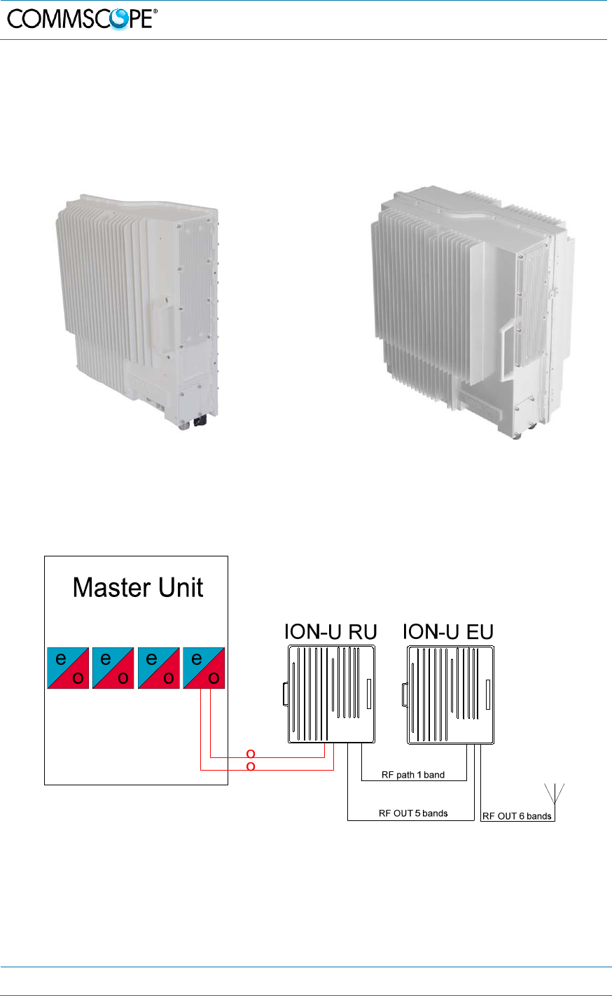
The following figures show views of a single Remote Unit for SISO applications and
two Remote Units paired for MIMO applications.
figure 3-1 Remote Unit, SISO figure 3-2 Remote Unit, MIMO two
units paired
The ION-U EU L 23/23 Extension unit with integrated antenna port combiner together
with ION-U L 7/80-85/17(E)P/19P allows for further options.
figure 3-3 One RU one EU one antenna
3. Functional Description
MF0200A5C_ION-U_L_7_80-85_17EP_19P.docx Manual for ION
®
-U Page 19
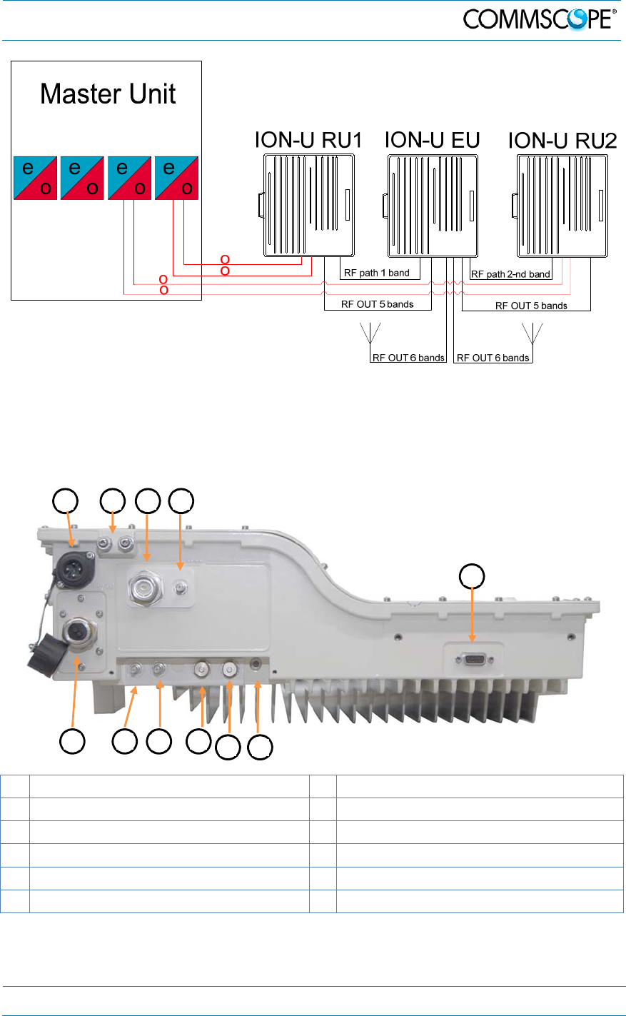
figure 3-4 Two RUs one EU two antennas
3.3. ION-U Low Power RU Ports
The RF, optical, mains power, alarm, power control, and expansion ports are located
on the bottom of the RU.
A Mains power connector G Pwr/Ctrl connector
B Grounding (earthing) bolts H Alarm connector
C RF antenna port I Expansion UL port
D Probe J Expansion DL port
E Local Port RS-232 K Optical ports
F Status LED
figure 3-5 RU connectors and Status LED
A
B C D
E
FG
H I J K

3. Functional Description
Page 20 MF0200A5C_ION-U_L_7_80-85_17EP_19P.docx Manual for ION
®
-U
Mains Connector
The RU receives its power through the Mains connector . The type of connector is
dependent on the RU model. A 4-pin Amphenol connector is used for AC models and
standard DC models. A 7-pin Amphenol connector is used for DC models powered
by a dual cable supply.
Antenna Port
The RU has one duplex 4.3-10 (1-st generation RUs: N-female) antenna port for
transmitting and receiving signals to and from distributed antennas. This RF port can
be connected directly to an antenna (i.e. using RF jumper cables) or through splitters,
allowing additional antennas to be fed by the RU.
Probe
This port is used as measurement probe to antenna port.
Local Port RS-232
The RS-232 port is standard DB-9 female connector used for external modem
communication with an optional Extension Unit.
Status LED
The status LED provides a visual warning of an alarm condition. The color of the
LED indicates the severity of the alarm.
Pwr/Ctrl Connector
The Pwr/Ctrl connector supports an optional fan unit. The RU provides power and
fan speed control to the fan unit and receives alarms from it through this 7-pin Binder
connector.
Alarm Connector
The RU has two alarm relay inputs that can be used to monitor and report alarms
from external devices. The alarm connector is a 5-pin Binder connector.
Expansion Ports
The Expansion UL and Expansion DL ports are QMA female connectors that
are used to connect to a CommScope EU to provide additional bands.
Optical Ports
The LC-APC optical connectors are used to send and receive the signals between
the RU and the Master Unit’s OTRx modules.
The DL optical port receives downlink signals from the MU OTRx.
The UL optical port transmits uplink signals to the MU OTRx.
A
C
D
E
F
G
H
I
J
K
4. Commissioning
MF0200A5C_ION-U_L_7_80-85_17EP_19P.docx Manual for ION
®
-U Page 21
4. Commissioning
Read and observe the health and safety and property damage warnings as well as
the description carefully to avoid mistakes and proceed step-by-step as described.
Attention: Do not operate the Remote Unit without terminating the antenna
connectors. The antenna connectors may be terminated by connecting them
to their respective antennas or to a dummy load.
Notice: Only qualified personnel should carry out the electrical, mechanical,
commissioning, and maintenance activities that require the unit to be powered
on when open.
When opening the Remote Unit do not damage the warranty labels on the
internal devices. The warranty is void if the seals are broken.
Ensure that all connections have been performed according to chapter 4.2.3
Connections.
Unless otherwise agreed to in writing by CommScope, CommScope’s general limited
product warranty (http://www.commscope.com/Resources/Warranties/) shall be the
warranty governing the Remote Units, including the installation, maintenance, usage
and operation of the Remote Units.
4.1. Low Power RU Mechanical Installation
4.1.1. Health and Safety for mechanical installation
Read and observe chapter 1.2 Health and Safety.
1. Caution: Risk of injury by the considerable weight of the unit falling. Ensure there
is adequate manpower to handle the weight of the system.
2. Caution: Risk of serious personal injury by equipment falling due to improper
installation. The installer must verify that the supporting surface will safely
support the combined load of the electronic equipment and all attached hardware
and components. The screws and dowels (wall anchors) used should also be
appropriate for the structure of the supporting wall.
4.1.2. Property Damage Warnings for mechanical installation
1. Attention: Do not install the unit in a way or at a place where the specifications
outlined in the Environmental and Safety Specifications leaflet of the supplier are
not met.
2. Attention: Due to power dissipation, the unit may reach a very high temperature.
Ensure sufficient airflow for ventilation.
3. Notice: Exceeding the specified load limits may cause the loss of warranty.
4. Notice: When connecting and mounting the cables (RF, optical, mains, ...)
ensure that no water can penetrate into the unit through these cables.
4. Commissioning
Page 22 MF0200A5C_ION-U_L_7_80-85_17EP_19P.docx Manual for ION
®
-U
5. Notice: If any different or additional mounting material is used, ensure that the
mounting remains as safe as the mounting designed by the manufacturer. The
specifications for stationary use of the Unit must not be exceeded. Ensure that
the static and dynamic strengths are adequate for the environmental conditions
of the site. The mounting itself must not vibrate, swing or move in any way that
might cause damage to the Unit.
Specified torques must be observed for certain mounting procedures according to the
following table:
Type Pins Hex nuts Screws
Thread M 6 M 6 M6
Specified torques 3.3 N-m 3.3 N-m 3.3 N-m
table 4-1 Specified torques
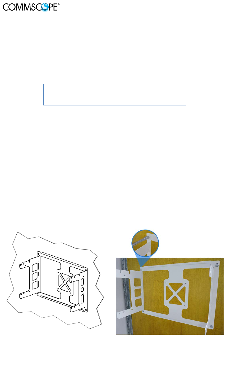
4.1.3. Mounting bracket
4.1.3.1. Mount to a wall
1. Check the suitability of the wall-mounting kit and the wall.
2. Install the mounting bracket using 4 M6 screw anchors (not included*) or suitable
lag bolts according to the drilling layout. Confirm that the bracket is securely
fastened to the wall. Installer must verify that the supporting surface will safely
support the combined load of the electronic equipment and all attached hardware
and components.
* The M6 screw anchors are not included as part of the RU delivery because the suitable type
depends on the on-site conditions (wall structure and materials). Use screw anchors that are
appropriate for the mounting surface.
figure 4-1 Mounting bracket
4. Commissioning
MF0200A5C_ION-U_L_7_80-85_17EP_19P.docx Manual for ION
®
-U Page 23
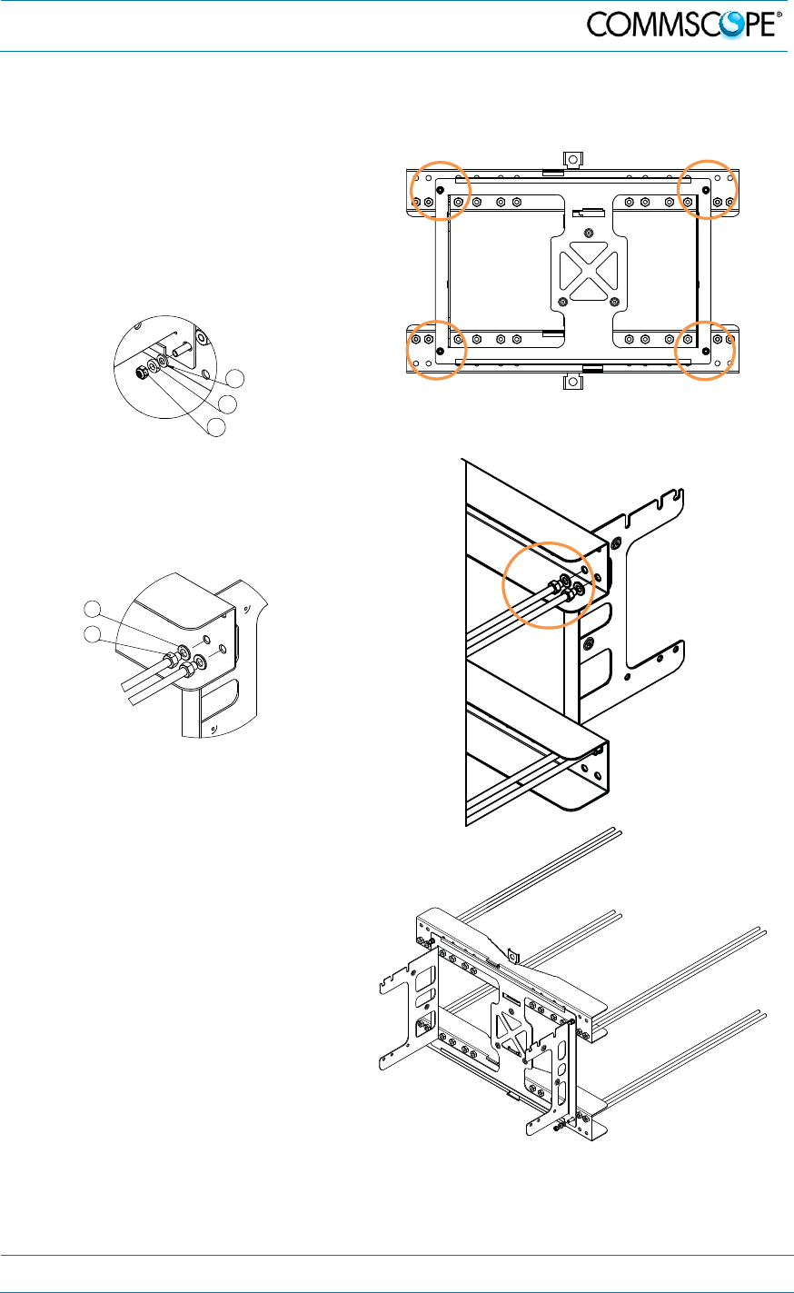
4.1.3.2. Mount to a pole
Mounting kits are available for poles from 4“ to 18” (10.2 cm to 45.8 cm) and for 40”
(1 m).
1. Mount the mounting bracket to
the four screw pins of the two
pole-mounting brackets with M6
plain washers (9), split lock
washers (10) and self lock nuts
(8).
2. Screw a M8 nut (4) to one end of
each of the eight threaded bolts
and slide a plain washer (5) on
the bolt.
3. Screw the end of the threaded
bolts (with the nut and washer)
from the inner side to the welded
nuts of the pole-mounting
bracket. Use the nuts that allow
to mount the mounting kit with
the threaded bolts as close to the
pole as possible. Lock the
screwing by fastening the M8
nut.
4x
8
10
9
4
5
4. Commissioning
Page 24 MF0200A5C_ION-U_L_7_80-85_17EP_19P.docx Manual for ION
®
-U
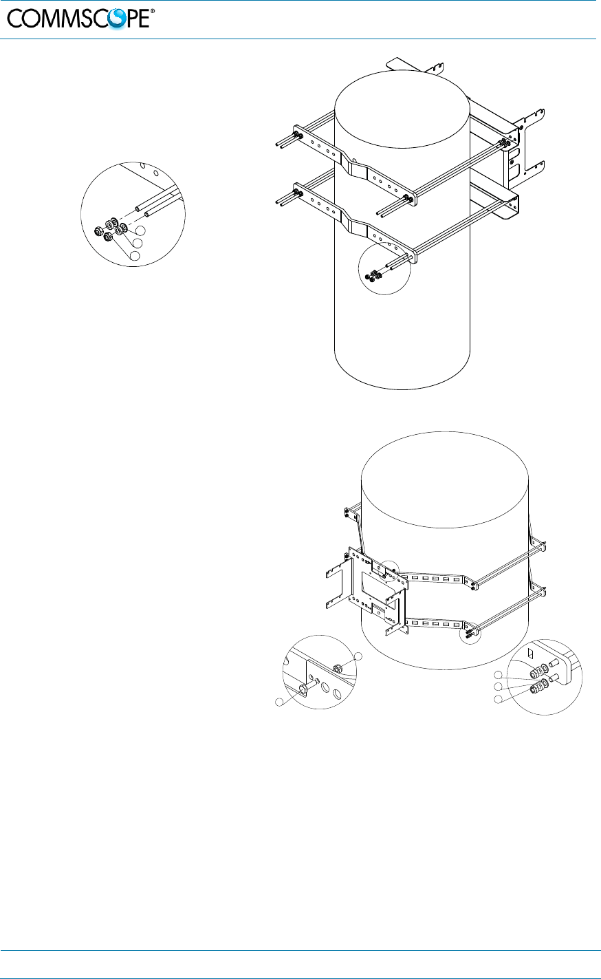
4. Mount the pole-mounting kit with
the two brackets and M8 plain
washers (5), split lock washers
(6), and self lock nuts (7) to the
pole.
Take care to mount the brackets
congruently and not at an angle.
figure 4-2 Pole-mounting kit 4" to 18"
Mounting the 40” pole-mounting kit
is similar, except:
the pole-mounting bracket
provides no screw pins, but the
mounting bracket is fastened
with four screws M8 x 25 (2) and
M8 self lock nuts (3).
the pole-mounting bracket
provides no welded nuts but all
the threaded bolts are mounted
with M8 plain washers (7), split
lock washers (6) and nuts.
figure 4-3 Pole-mounting kit 40”
7
6
5
2
3
3
6
7
4. Commissioning
MF0200A5C_ION-U_L_7_80-85_17EP_19P.docx Manual for ION
®
-U Page 25
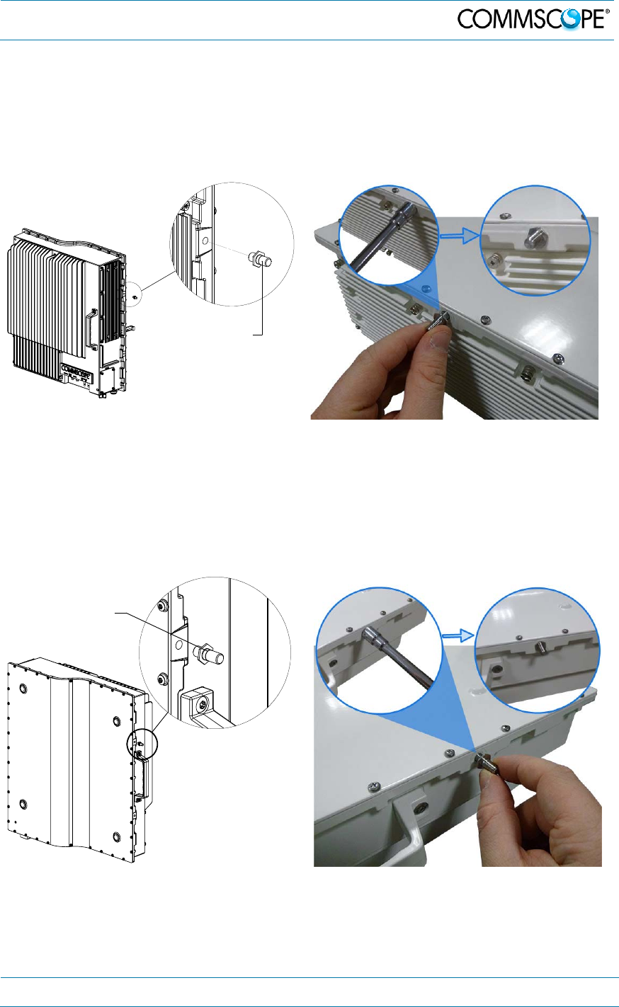
4.1.4. Threaded pins
1. Attach an M6 threaded pin to the unit by inserting it into the threaded hole
adjacent to the power supply and turning it clockwise. Tighten the pin securely
with a socket wrench.
figure 4-4 RU threaded pin power supply side
2. Attach an M6 threaded pin to the nit by inserting it into the threaded hole above
the handle and turning it clockwise. Tighten the pin securely with a socket
wrench.
figure 4-5 RU threaded pin narrow side
M6 threaded pin
M6 threaded pin
4. Commissioning
Page 26 MF0200A5C_ION-U_L_7_80-85_17EP_19P.docx Manual for ION
®
-U
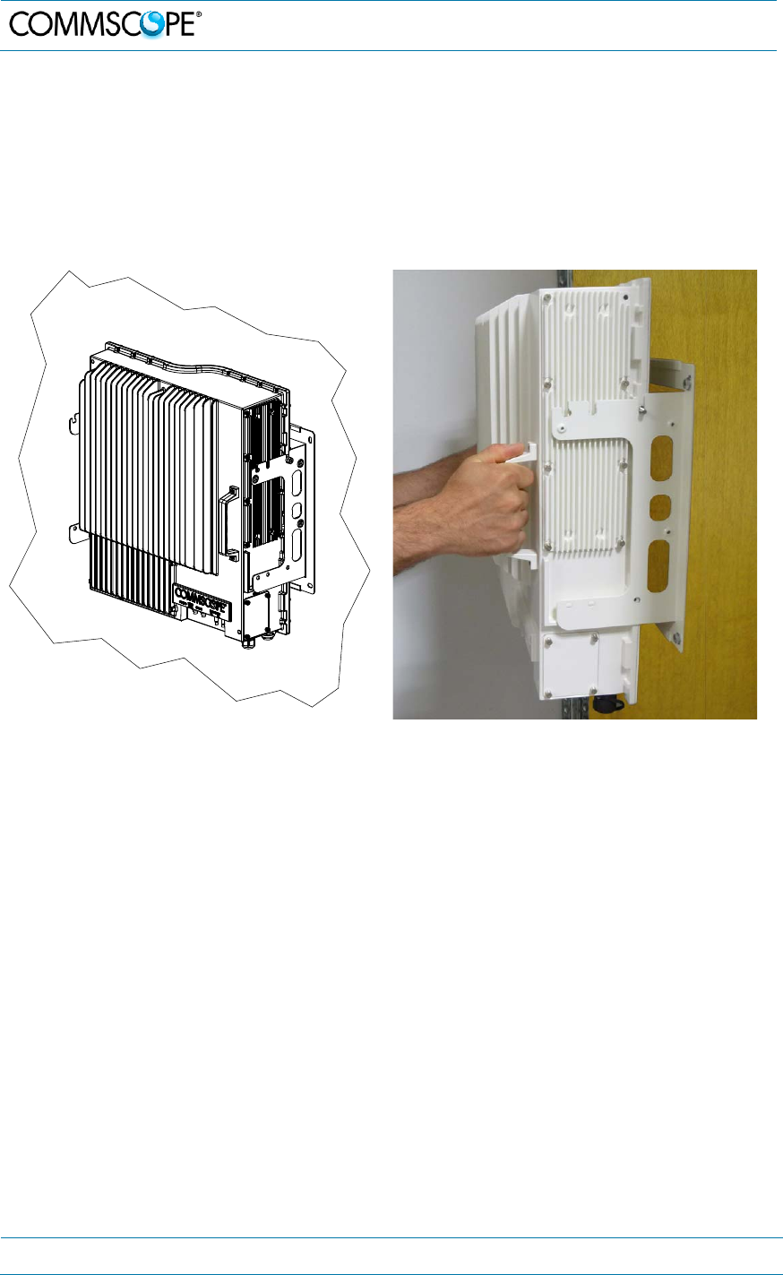
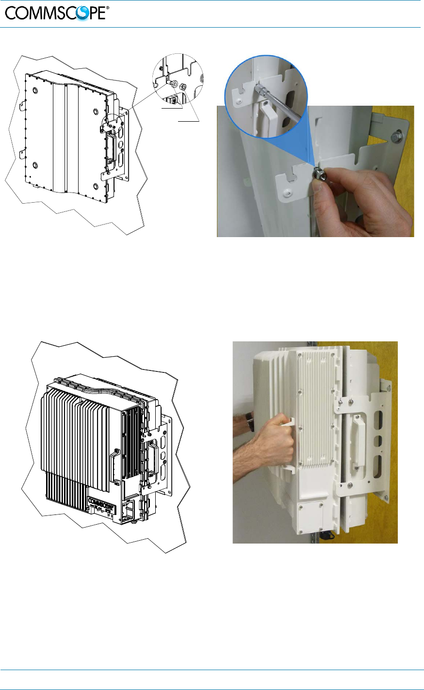
4.1.5. Wall mounting procedure – Single Unit (SISO)
1. Follow the instructions for mounting the bracket and installing the threaded
pins in chapter 4.1.3.
2. Install the unit on the wall-mounting bracket by lifting it into place and using
both handles and lowering it down onto the bracket. The M6 pins must align
with the slots in the bracket to support the unit.
figure 4-6 Place RU onto wall mounting bracket – single mount
4. Commissioning
MF0200A5C_ION-U_L_7_80-85_17EP_19P.docx Manual for ION
®
-U Page 27
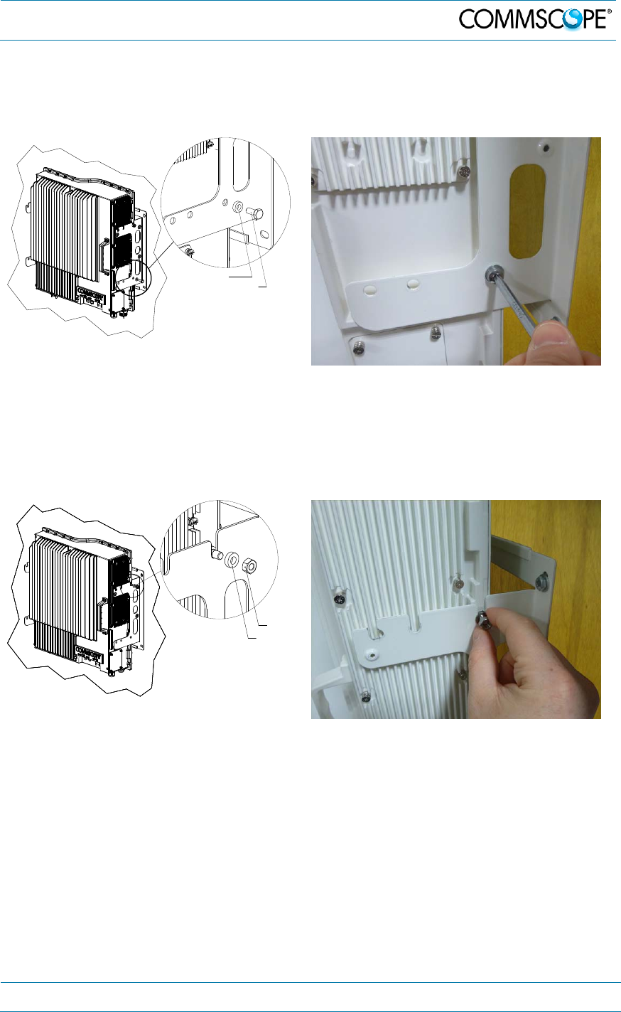
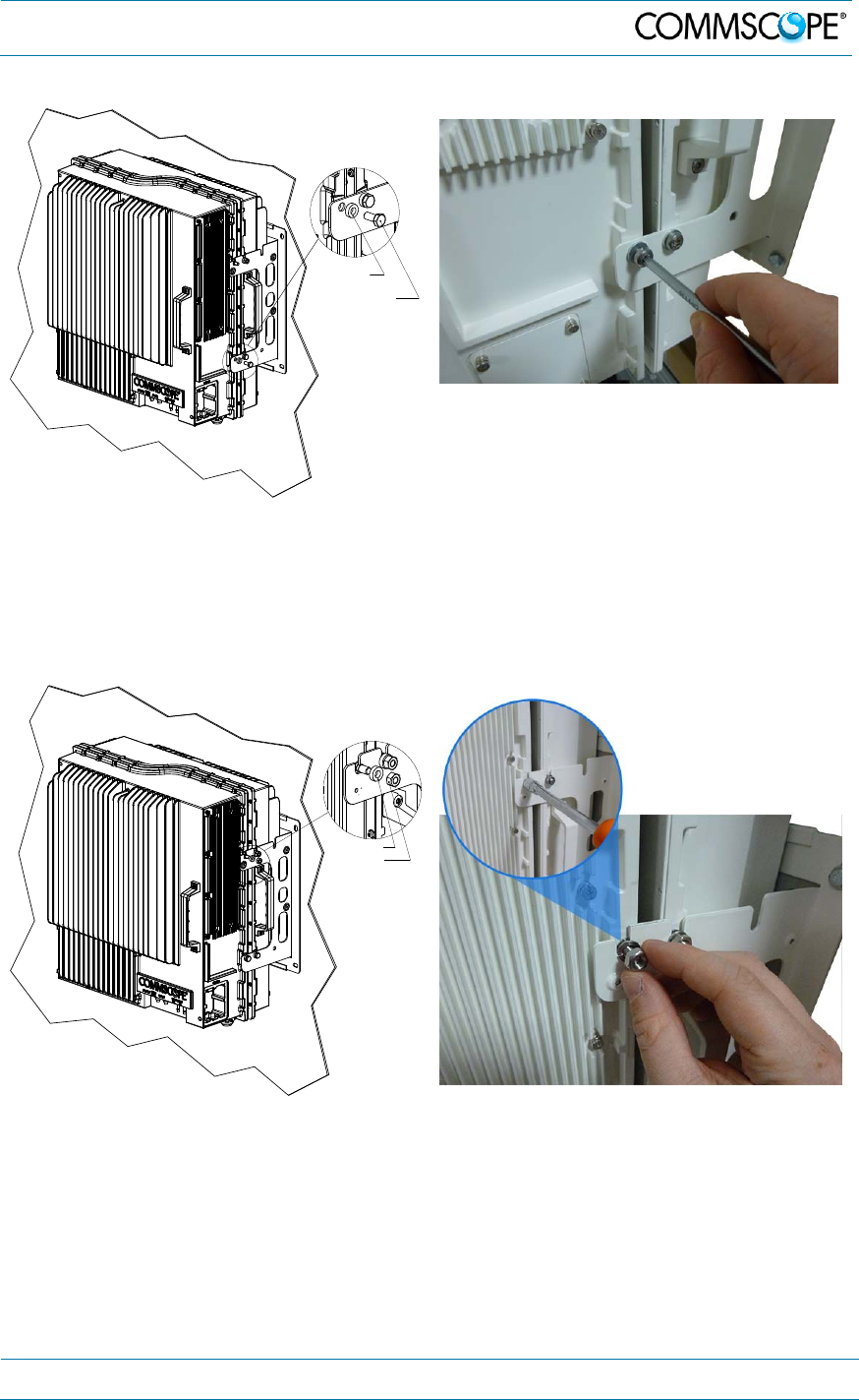
3. Fasten the lower section of the unit to the bracket using a washer and an
M6x12 screw (on both sides). Slide a washer over each screw and then insert
the screw and tighten it securely.
figure 4-7 Install M6x12 screws and washers for single mount
4. Fasten the unit to the bracket using a washer and M6 nut. Slide the washer
over the threaded pins that you installed previously (chapter 4.1.3) and then
screw the nut onto the pins (on both sides) and tighten securely.
figure 4-8 Attach M6 nut to threaded pins for single mount
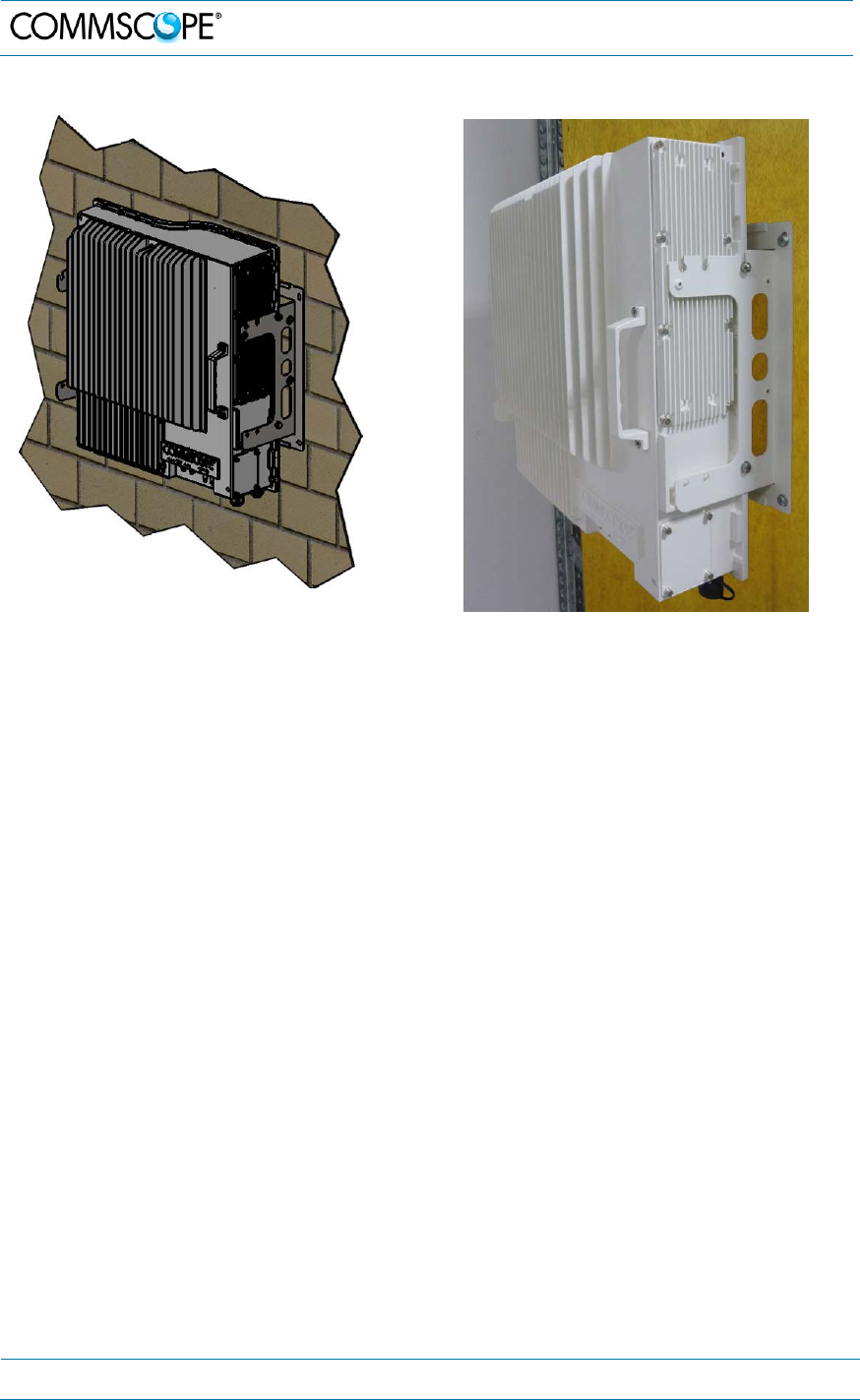
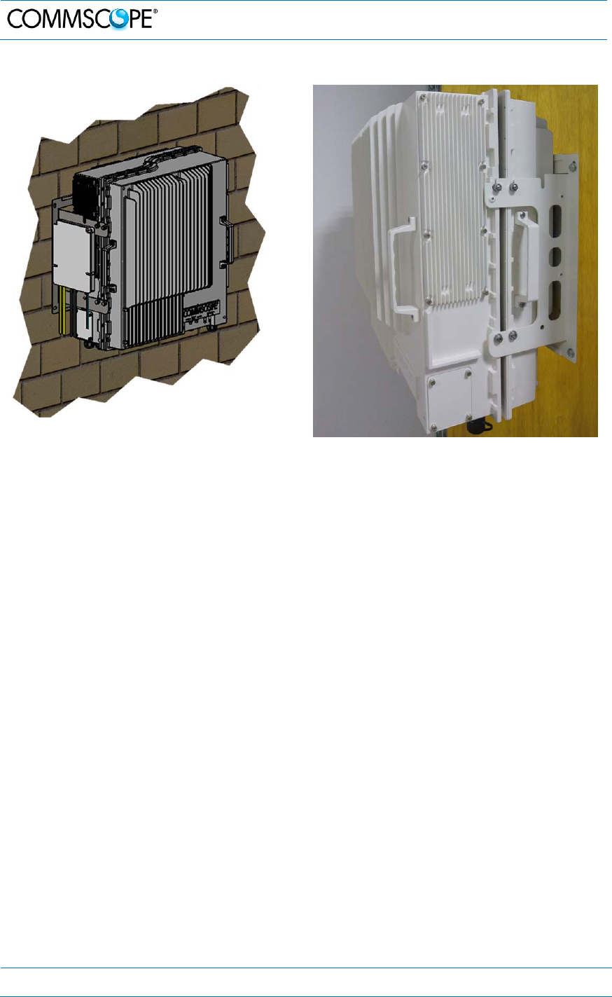
5. Confirm that all screws and nuts have been fastened and the unit is securely
mounted to the wall.
M6x12 screw
Washer
M6 nut
Washer
4. Commissioning
Page 28 MF0200A5C_ION-U_L_7_80-85_17EP_19P.docx Manual for ION
®
-U
figure 4-9 Completed SISO RU mount
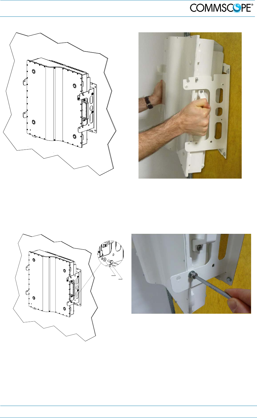
4.1.6. Wall mounting procedure – Dual Units (MIMO)
For MIMO operation, two LP RUs are mounted on a single wall bracket.
1. Follow the instructions for mounting the bracket and installing the threaded pins
in chapter 4.1.3.
2. Install the first Remote Unit on the wall-mounting bracket by lifting the RU into
place and lowering it down onto the bracket. The M6 pins must align with the
slots in the bracket to support the RU. Note that the first RU is installed with the
curved side facing you, which is the opposite of the installation procedure for
SISO (one unit) mounting.
4. Commissioning
MF0200A5C_ION-U_L_7_80-85_17EP_19P.docx Manual for ION
®
-U Page 29
figure 4-10 1
st
RU placed on wall mounting bracket - MIMO
3. Fasten the lower section of the first RU to the bracket using a washer and an
M6x12 screw (on both sides). Slide a washer over each screw and then insert
the screw and tighten it securely.
figure 4-11 Install M6x12 screws and washers
4. Fasten the RU to the bracket using a washer and M6 nut. Slide the washer over
the threaded pins that you installed previously (chapter 4.1.3) and then screw the
nut onto the pins (on both sides) and tighten securely.
M6x12 screw
Washer
4. Commissioning
Page 30 MF0200A5C_ION-U_L_7_80-85_17EP_19P.docx Manual for ION
®
-U
figure 4-12 Attach M6 nut to threaded pins
5. Install the second RU on the wall-mounting bracket by lifting the RU into place
and lowering it down onto the bracket. The 2
nd
RU is reversed in direction from
the 1
st
RU. The M6 pins must align with the slots in the bracket to support the
RU.
figure 4-13 2
nd
RU on wall mounting bracket
6. Fasten the lower section of the second RU to the bracket using a washer and an
M6x12 screw (on both sides). Slide a washer over each screw and then insert
the screw and tighten it securely.
Washer
M6 Nut
4. Commissioning
MF0200A5C_ION-U_L_7_80-85_17EP_19P.docx Manual for ION
®
-U Page 31
figure 4-14 Install M6x12 screws and washers 2
nd
RU
7. Fasten the RU to the bracket using a washer and M6 nut. Slide the washer over
the threaded pins that you installed previously (chapter 4.1.3) and then screw the
nut onto the pins (on both sides) and tighten securely.
figure 4-15 Attach M6 nut to threaded pins for 2
nd
RU
8. Confirm that all screws and nuts have been fastened and the unit is securely
mounted to the wall.
M6x12 screw
Washer
Washer
M6 Nut
4. Commissioning
Page 32 MF0200A5C_ION-U_L_7_80-85_17EP_19P.docx Manual for ION
®
-U
figure 4-16 Completed MIMO RU mount
4.1.7. Pole mounting procedure – SISO and MIMO
The pole mounting procedures are identical to the wall mounting procedures
described in chapters 4.1.5 Wall mounting procedure – Single Unit (SISO) and 4.1.6
Wall mounting procedure – Dual Units (MIMO), except for the mounting of the
mounting bracket described in chapter 4.1.3.2 Mount to a pole.

4. Commissioning
MF0200A5C_ION-U_L_7_80-85_17EP_19P.docx Manual for ION
®
-U Page 33
4.2. Low Power RU Electrical Installation
4.2.1. Health and Safety for electrical installation
Read and observe chapter 1.2 Health and Safety.
1. Danger: Electrical hazard. Danger of death or fatal injury from electrical
current. Obey all general and regional installation and safety regulations
relating to work on high voltage installations, as well as regulations
covering correct use of tools and personal protective equipment.
2. Danger: Electrical hazard. Danger of death or fatal injury from electrical
current inside the unit in operation. Before opening the unit, disconnect
mains power.
4.2.2. Property Damage Warnings for electrical installation
1. Attention: It is compulsory to ground (earth) the unit before connecting the
power supply. Grounding bolts are provided on the cabinet to connect the
ground-bonding cable.
2. Attention: If the mains connector of the unit is not easily accessible, a
disconnect device in the mains power circuit must be provided within easy reach.
3. Attention: A connection of the mains supply to a power socket requires the
power socket to be nearby the unit.
4. Attention: Before connecting or disconnecting the mains connector at the unit,
ensure that mains power supply is disconnected.
5. Attention: Make sure that an appropriate circuit breaker acting as a disconnect
device (as required by IEC/EN60950-1) and an overcurrent limiting device are
connected between mains power and the unit.
6. Attention: Incorrectly wired connections can destroy electrical and electronic
components.
7. Notice: To avoid corrosion at the connectors caused by electrochemical
processes, the material of the cable connectors must not cause a higher potential
difference than 0.6 V (see electrochemical contact series).

4. Commissioning
Page 34 MF0200A5C_ION-U_L_7_80-85_17EP_19P.docx Manual for ION
®
-U
8. Notice: Use an appropriate torque wrench for the coupling torques:
- for N-type connectors (2 N-m / 20 in lb) with 13/16 in opening,
e. g. item no. 244379 available from the CommScope e-catalog
- for 4.3-10 type connectors (5 N-m, 44 in lb) with 22mm (7/8) in
opening
Do NOT use your hands or any other tool (e.g. a pair of pliers). This might cause
damage to the connector and lead to a malfunction of the unit.
9. Notice: For unstabilized electric networks, which frequently generate spikes, the
use of a voltage limiting device is advised.
10. Notice: Observe the labels on the front panels before connecting or
disconnecting any cables.
11. Notice: Unused connectors must be closed with their protective covers to
ensure water tightness.

4. Commissioning
MF0200A5C_ION-U_L_7_80-85_17EP_19P.docx Manual for ION
®
-U Page 35
4.2.3. Connections
ION-U Low Power RU Connectors/Indicators
Port/Conn Purpose Type
MAINS
(Vac/Vdc)
This connector provides the power to RU models
that use standard AC (85 to 265 Vac) or RU
models that use standard DC (-60 to -38 Vdc)
power.
Amphenol C016
Series, 4-Pin
Grounding
Bolts
Ground (earth) bolts for connecting the
mandatory ground cable to the RU. M6 bolts, hex
nut, & washers
ANT RF
This connector is used for transmitting and
receiving signals to and from an antenna or
antenna splitter.
4.3-10 female
(1-st generation
N-type female)
PROBE
This port is used as measurement probe to
antenna port. QMA Female
LOCAL
RS-232
This connector is used for external modem
communication with an optional Extension unit.
DB-9 Female
STATUS
This LED provides a visual warning of an alarm
condition. The color of the LED indicates the
severity of the alarm.
LED
PWR/CTRL
This connector supports an optional fan unit. The
RU provides power and fan speed control to the
fan unit and receives alarms from it.
Binder 712
series 7-pin
ALARM
This connector provides alarm contacts that are
used to monitor and report alarms generated by
other equipment.
Binder 712
series 5-pin
EXPANSION
UL
This connector is used to connect to the UL port
of an expansion unit to provide additional bands
of coverage.
QMA Female
EXPANSION
DL
This connector is used to connect to the DL port
of an expansion unit to provide additional bands
of coverage.
QMA Female
OPTICS UL
This connector is used to connect an optical fiber
cable to send uplink signal back to the OTRx
module of the ION-U master unit.
LC-APC
OPTICS DL
This connector is used to connect an optical fiber
cable to receive downlink signal from the OTRx
module of the ION-U master unit.
LC-APC
MAINS
(Vdc/100)
This connector provides the power to RU models
used in locations where the power drawn on each
cable must be limited to a maximum of 100 VA.
Amphenol C016
Series, 7-Pin
table 4-2 ION-U Low Power RU connectors - description
4. Commissioning
Page 36 MF0200A5C_ION-U_L_7_80-85_17EP_19P.docx Manual for ION
®
-U
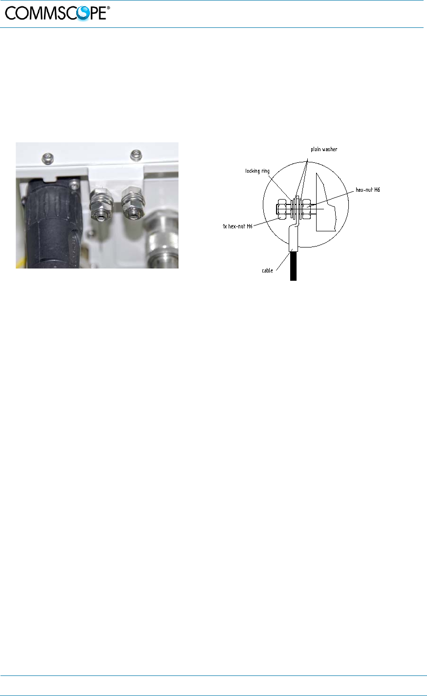
4.2.4. Grounding (Earthing)
The RU must be grounded (earthed).
1. Connect an earth-bonding cable to the grounding bolt connection provided on the
outside of the unit (near the Mains connector) as shown in figure 4-17. Do not
use the grounding connection to connect external devices.
figure 4-17 Grounding bolts figure 4-18 Grounding bolt, schematic view
2. After loosening the hex nut(s), connect the earth-bonding cable between the two
washers as illustrated in the figures above.
3. Then, fasten all parts again by tightening the hex nut(s).
4. Connect the other end of the ground wire to a suitable permanent ground
following local electrical code practices.
4. Commissioning
MF0200A5C_ION-U_L_7_80-85_17EP_19P.docx Manual for ION
®
-U Page 37
4.2.5. Mains power connection
Before connecting electrical power to the units, the system must be grounded
(earthed) as described in the previous chapter.
The Mains power must be connected to the Mains connector of the unit for operation
of the RU. A power cable is delivered with each RU. The type of power cable
delivered is dependent on the type of power supply in the unit.
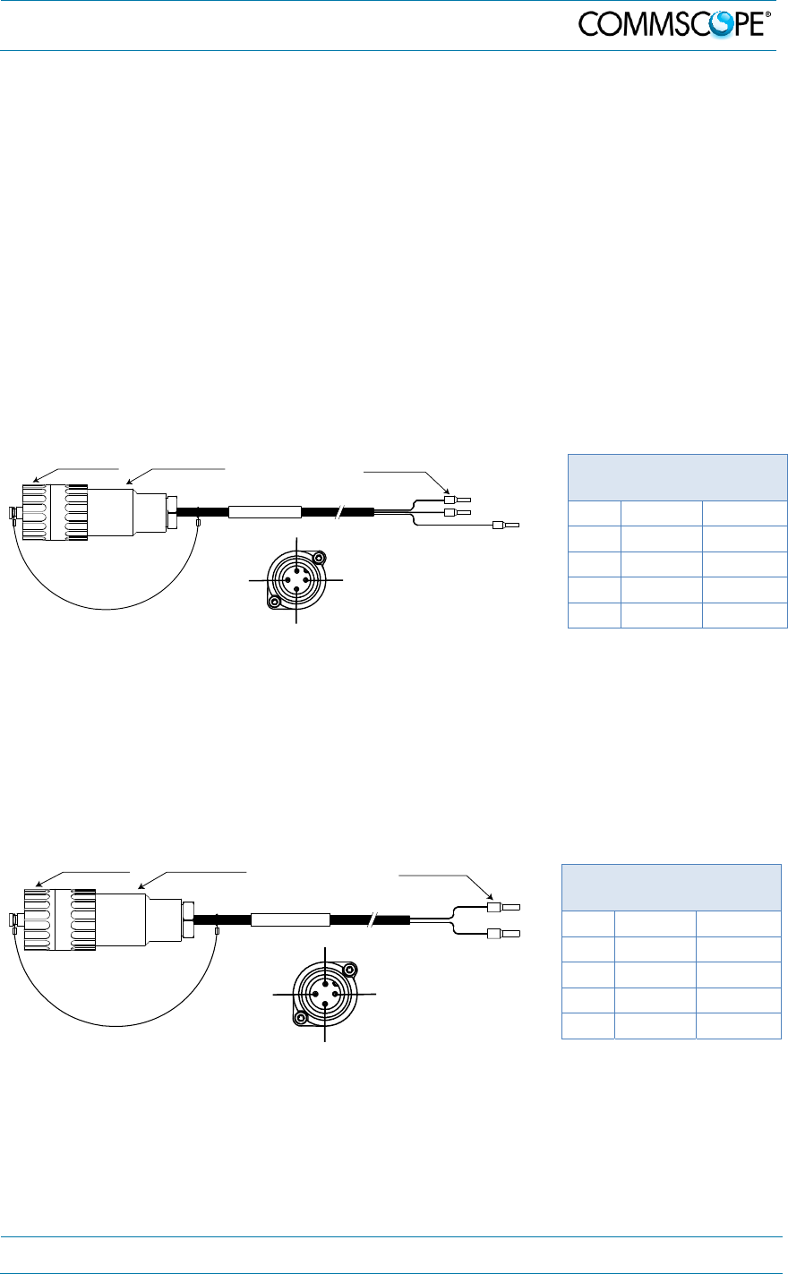
The AC power cable is a 3.2 m (10.5 ft) 16 AWG cable with a 4-pin Amphenol C016
series plug on one end to connect to the RU Mains connector. The other end of the
cable is un-terminated with 3 end splices to connect to the AC power source. A 10 m
(33.7 ft) AC power cable is also available as an option. The AC power cable is shown
in figure 4-19.
4-Pin Amphenol C016
Series
Pin Name Color
1 Phase Black
2 Neutral White
3 n.c. n.c
4 Ground Green
figure 4-19 AC power cable table 4-3
AC power cable
The standard DC power cable is a 3.2 m (10.5 ft) 13 AWG cable with a 4-pin
Amphenol C016 series plug on one end to connect to the RU Mains connector. The
other end of the cable is un-terminated with 2 end splices to connect to the -48 Vdc
power source. The standard DC power cable is shown in figure 4-20.
4-Pin Amphenol C016
Series
Pin Name Color
1 n.c n.c
2 –48V Black
3 0V Red
4 n.c. n.c
figure 4-20 DC power cable table 4-4
DC power cable
black
A
m
phenol 4-Pin
female connector
Protective Cap 3x end splice
white
green
B0400A4
A
RU Mains
Connector
4
3
2
1
black
Amphenol 4-Pin
female connector
Protective Cap 2x end splice
red
B0400A5A
RU Mains
Connector
4
3
2
1
4. Commissioning
Page 38 MF0200A5C_ION-U_L_7_80-85_17EP_19P.docx Manual for ION
®
-U
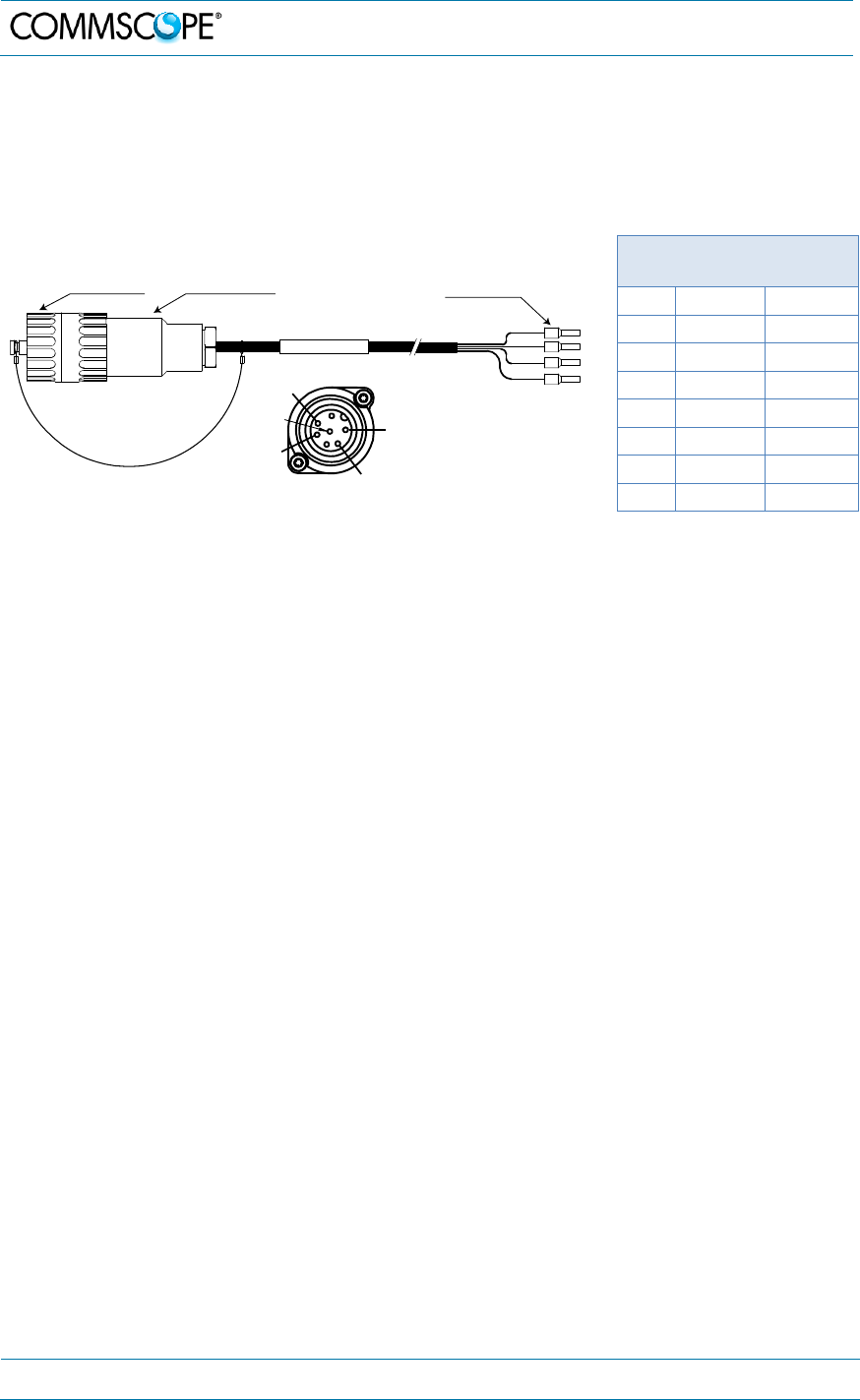
The Vdc/100 power cable is available for locations where the power drawn on each
cable must be limited to a maximum of 100 VA. This cable is a 3.2 m (10.5 ft) 16
AWG cable with a 7-pin Amphenol C016 series plug on one end to connect to the RU
Mains connector. The other end of the cable is un-terminated with 4 end splices to
connect to the -48 Vdc power source.
7-Pin Amphenol C016
Series
Pin Name Color
1 0V White
2 –48V Black
3 n.c. -
4 0V Red
5 –48V Green
6 n.c -
7 n.c -
figure 4-21 Vdc/100 power cable table 4-5 Vdc/100 power
cable
Notice: For the AC power supply connection, a minimum cross section of 1.5 mm
2
is
required and for the DC power supply connection, a minimum cross section of
2.5 mm
2
is required. Each wire must observe the applicable national regulations
regarding loop impedance, voltage drop, and methods of installation. Make sure
to connect the correct voltage to the unit.
Notice: Do not connect or disconnect the power cable at the mains connector while
power is on. Turn off mains* power before connecting the power cable at the unit,
then, engage mains power again.
* Mains power must be interruptible with an external delay-actions mains breaker.
For the mains breaker, observe the following recommendation:
120 Volt / 20 Amp max. or 240 Volt / 16 Amp, single-phase, 50 / 60 Hz AC service is
needed, i.e. the external AC breaker should be 20 Amps max. for 120-Volt service or
13 to 16 Amps for 240-Volt service.
For the DC power supply, observe the local regulations of the DC service provider.
Use the following method to install and connect the Mains power to the RU:
1. Locate the Mains power cable that was delivered with the RU.
2. Locate or install a suitable power junction box or receptacle near the unit and
route the power cable from the power source to the RU. Do not connect the
cable to the unit’s Mains connector at this time. The power source must be
interruptible.
3. The Mains cable must be properly secured observing local regulations and
electrical codes. Be sure to allow enough slack in the cable at the RU to plug
or unplug the cable into the Mains connector.
1
2
4
5
7
Amphenol 7-Pin
female connector
Protective Cap 4x end splice
RU Mains
Connector
4. Commissioning
MF0200A5C_ION-U_L_7_80-85_17EP_19P.docx Manual for ION
®
-U Page 39
4. Wire the power cable to the junction box or receptacle. Refer to the color code
and pin numbers shown in figure 4-19 (AC cable), figure 4-20 (DC cable), or
figure 4-21 (Vdc/100 cable) depending on the type of power supply used by
the unit.
5. With the cable’s Mains plug disconnected from the RU, turn the circuit breaker
on, unscrew the plug’s protective cover, and carefully test the plug with a
voltmeter to ensure that the voltage and polarity are correct.
6. Once the testing has been completed, turn off the circuit breaker.
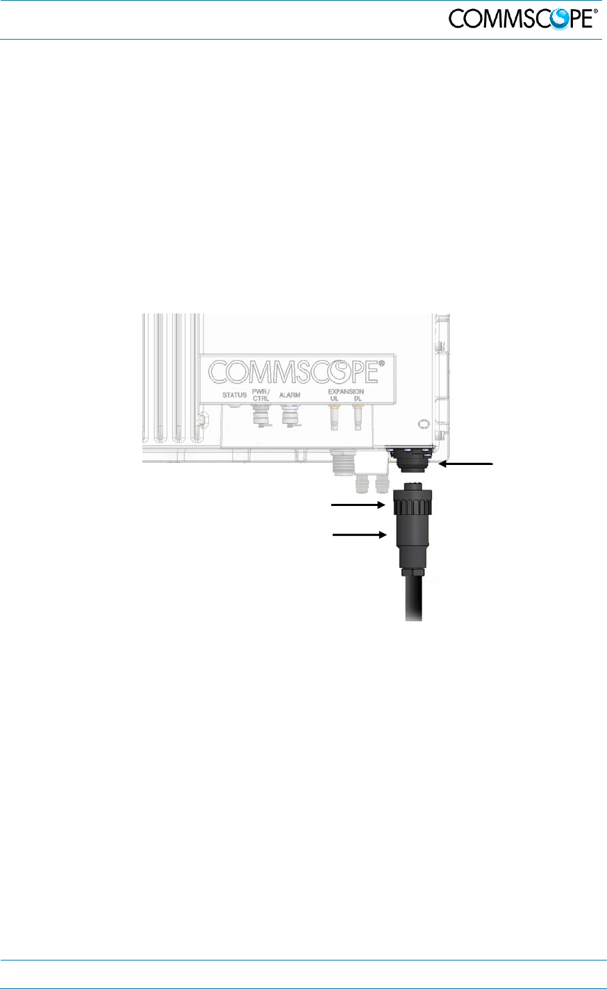
7. Unscrew the protective cover from the Mains connector of the unit.
8. Insert the plug into the Mains connector (figure 4-22) and tighten the clamping
ring until it is hand tight. Do not over-tighten the clamping ring.
figure 4-22 Connect mains plug
4.2.6. Antenna connection
The Remote Unit has one 4.3-10 (1-st generation: N-type) antenna connector (figure
4-23). For mounting the cable connector, it is recommended to refer to the
corresponding documentation of the connector manufacturer. The bending radius of
the antenna cables must remain within the given specifications.
Clamping ring
Mains plug
Mains
connecto
r
4. Commissioning
Page 40 MF0200A5C_ION-U_L_7_80-85_17EP_19P.docx Manual for ION
®
-U
The selection of cable and antenna is an important consideration. Choose the type of
cable best suited for the antenna. Consider that a cable with higher loss is less
expensive but impairs performance.
Notice: Use an appropriate torque wrench for the coupling torques:
- for N-type connectors (2 N-m / 20 in lb) with 13/16 in opening,
e. g. item no. 244379 available from the CommScope e-catalog
- for 4.3-10 type connectors (5 N-m, 44 in lb) with 22mm (7/8) in
opening
Do NOT use your hands or any other tool (e.g. a pair of pliers). This might cause
damage to the connector and lead to a malfunction of the unit.
Attention: To minimize passive inter-modulation (PIM) distortion, attention has to be
paid to the physical condition of the connector junctions:
Do not use connectors that show signs of corrosion on the metal surface.
Prevent the ingress of water or dirt into the connector.
Use protective caps for the connectors when not mounted.
Before mounting clean the connectors with dry compressed air.
Before mounting clean the mating surfaces of the connector with a lint-free
alcohol-drenched cloth on a wooden or non-metallic item.
Attach and torque the connectors properly.
Avoid metallic abrasion when mounting the connectors by only screwing the
connecting nut, but not turning the whole connector.
Use a torque wrench to fasten the connector, see above.
Clean the protective caps before mounting for antenna cable replacement.
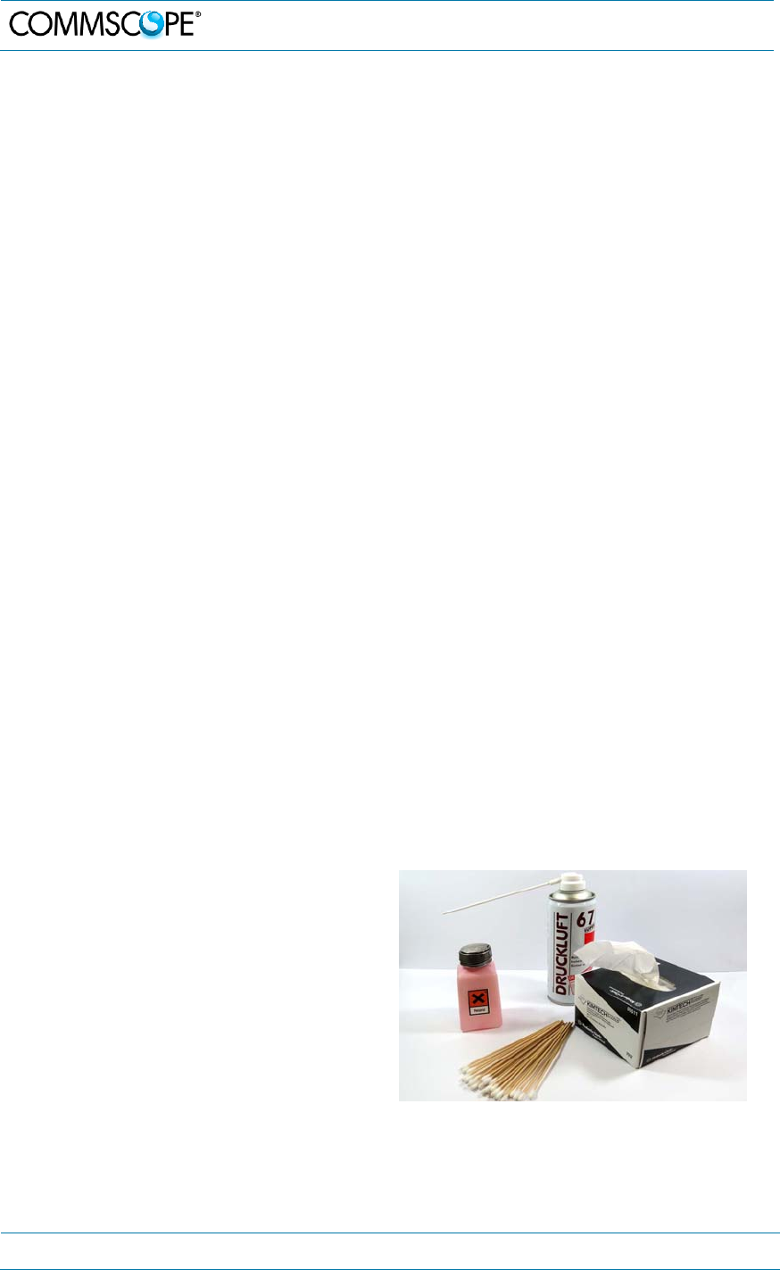
4.2.6.1. Cleaning procedure for RF cable connectors
1. What is needed for the cleaning?
a. Isopropyl alcohol or similar
b. Compressed air
c. Lint-free wipe
d. Cotton buds
4. Commissioning
MF0200A5C_ION-U_L_7_80-85_17EP_19P.docx Manual for ION
®
-U Page 41
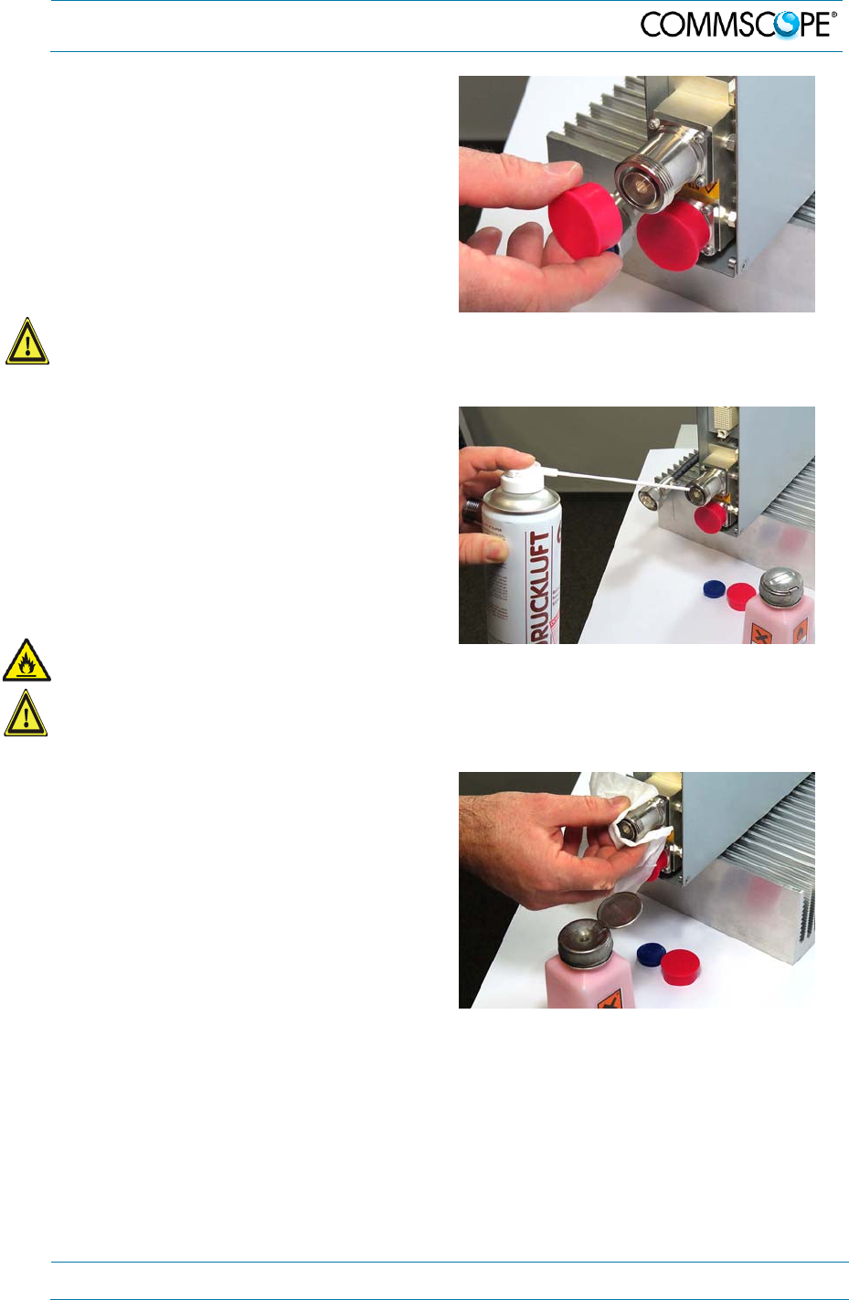
2. Remove protective cap from the RF
connector.
Caution: Risk of injury by flying particles when compressed air is used. Wear
protective clothing, especially protective glasses.
3. Remove metal chips and small
particles from the mating and inner
surfaces of the connector using
compressed air.
Warning: Flammable material. Risk of fire. Keep away from sources of ignition.
Caution: Eye irritant product. Risk of eye irritation. Avoid contact with eyes and skin.
Wear protective clothing, especially protective glasses.
4. Clean the connector winding with lint-
free wipe drenched with isopropyl
alcohol.
4. Commissioning
Page 42 MF0200A5C_ION-U_L_7_80-85_17EP_19P.docx Manual for ION
®
-U
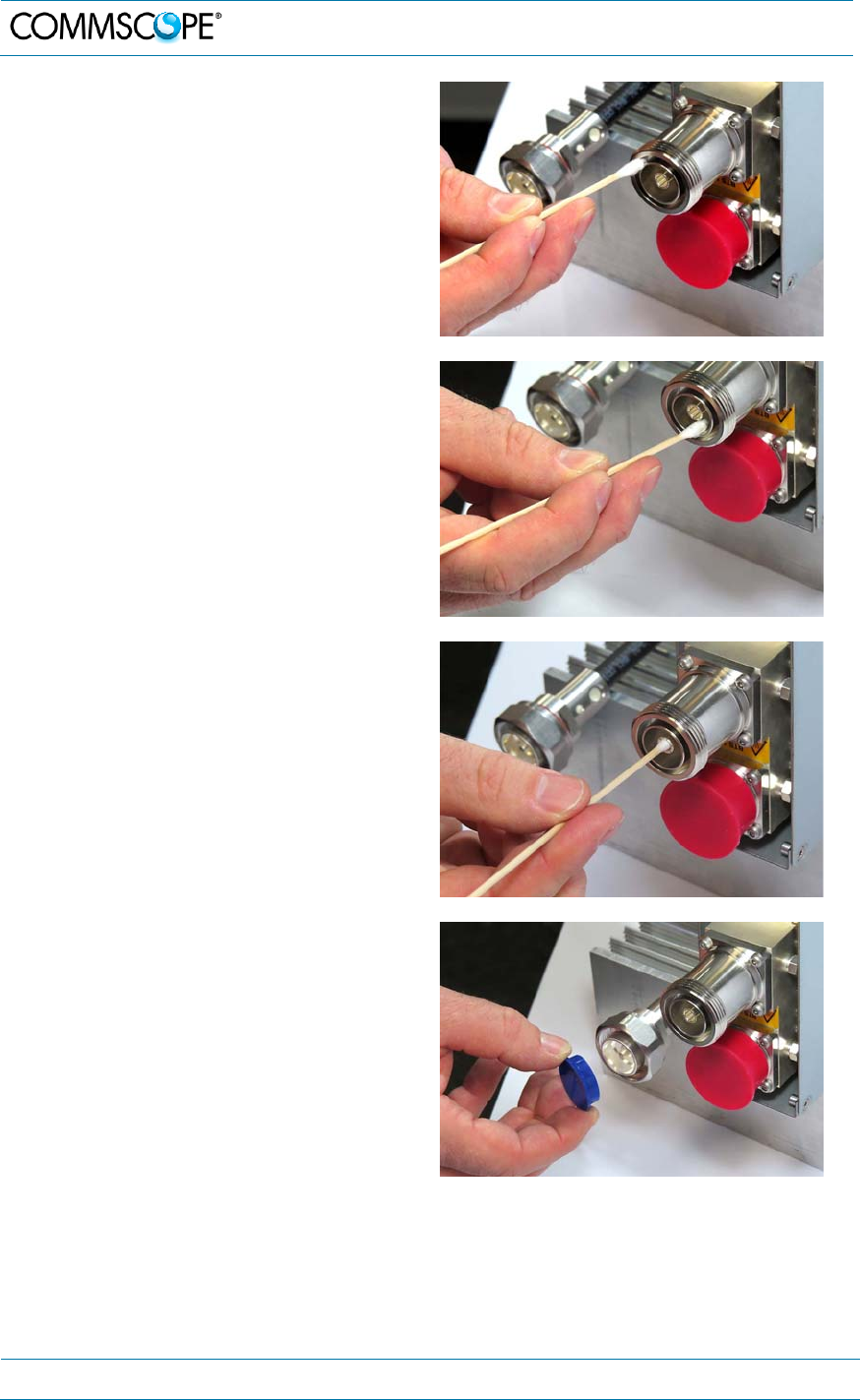
5. Clean the lip of the inner ring with a
cotton bud drenched with isopropyl
alcohol.
6. Clean the inside surface of the inner
ring with a cotton bud drenched with
isopropyl alcohol.
7. Clean the inside of the center
conductor spring tines with a cotton
bud drenched with isopropyl alcohol.
8. Clean in the similar way the
connector of the connected cable.
Remove protective caps from the unit
connector first.
4. Commissioning
MF0200A5C_ION-U_L_7_80-85_17EP_19P.docx Manual for ION
®
-U Page 43
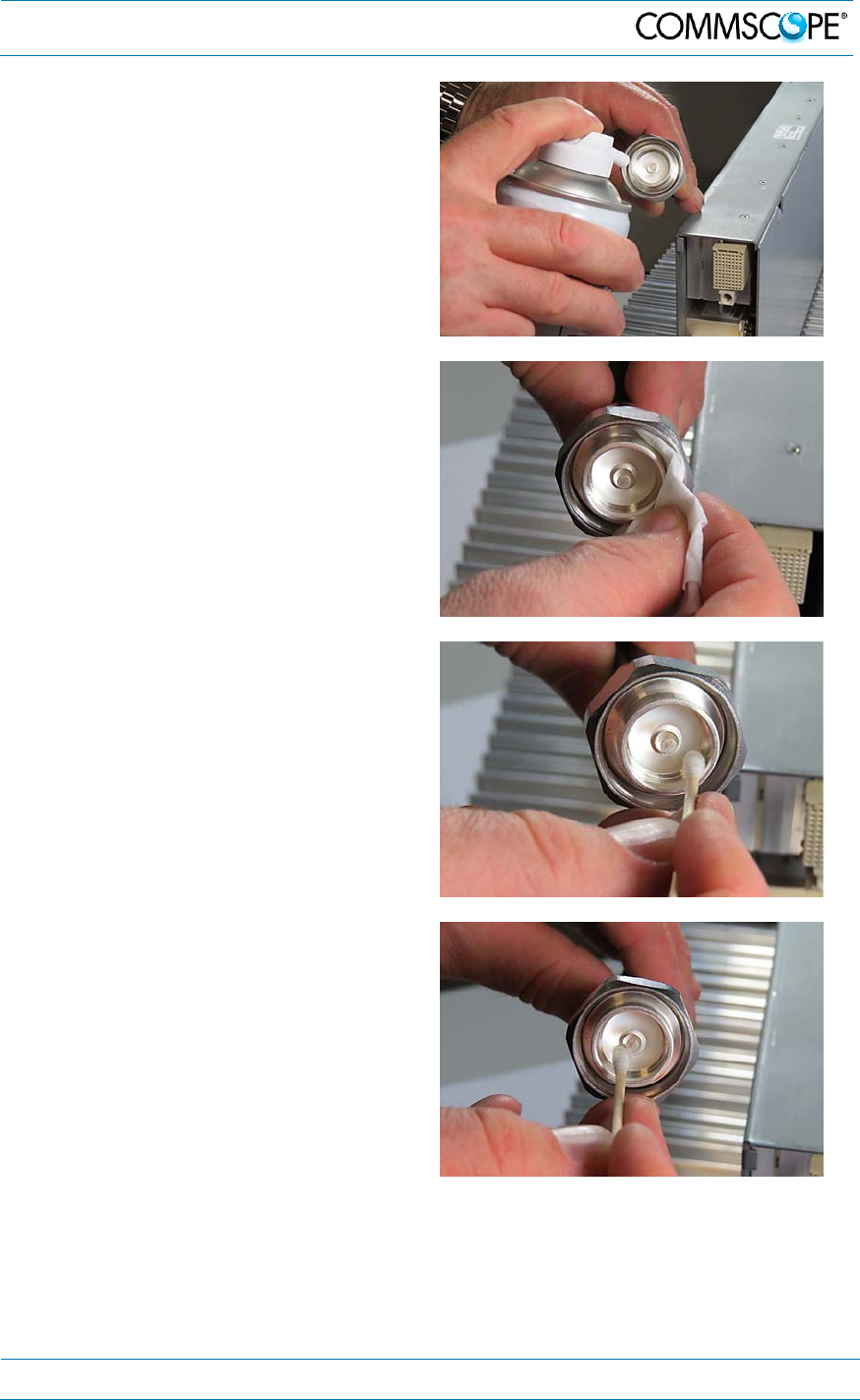
9. Remove metal chips and small
particles from the mating and inner
surfaces of the connector using
compressed air.
10. Continue with the winding area using
lint-free wipe drenched with isopropyl
alcohol.
11. Continue with the inside mating
surface of the inner ring.
12. Clean the outside surface of the
center pin.
4. Commissioning
Page 44 MF0200A5C_ION-U_L_7_80-85_17EP_19P.docx Manual for ION
®
-U
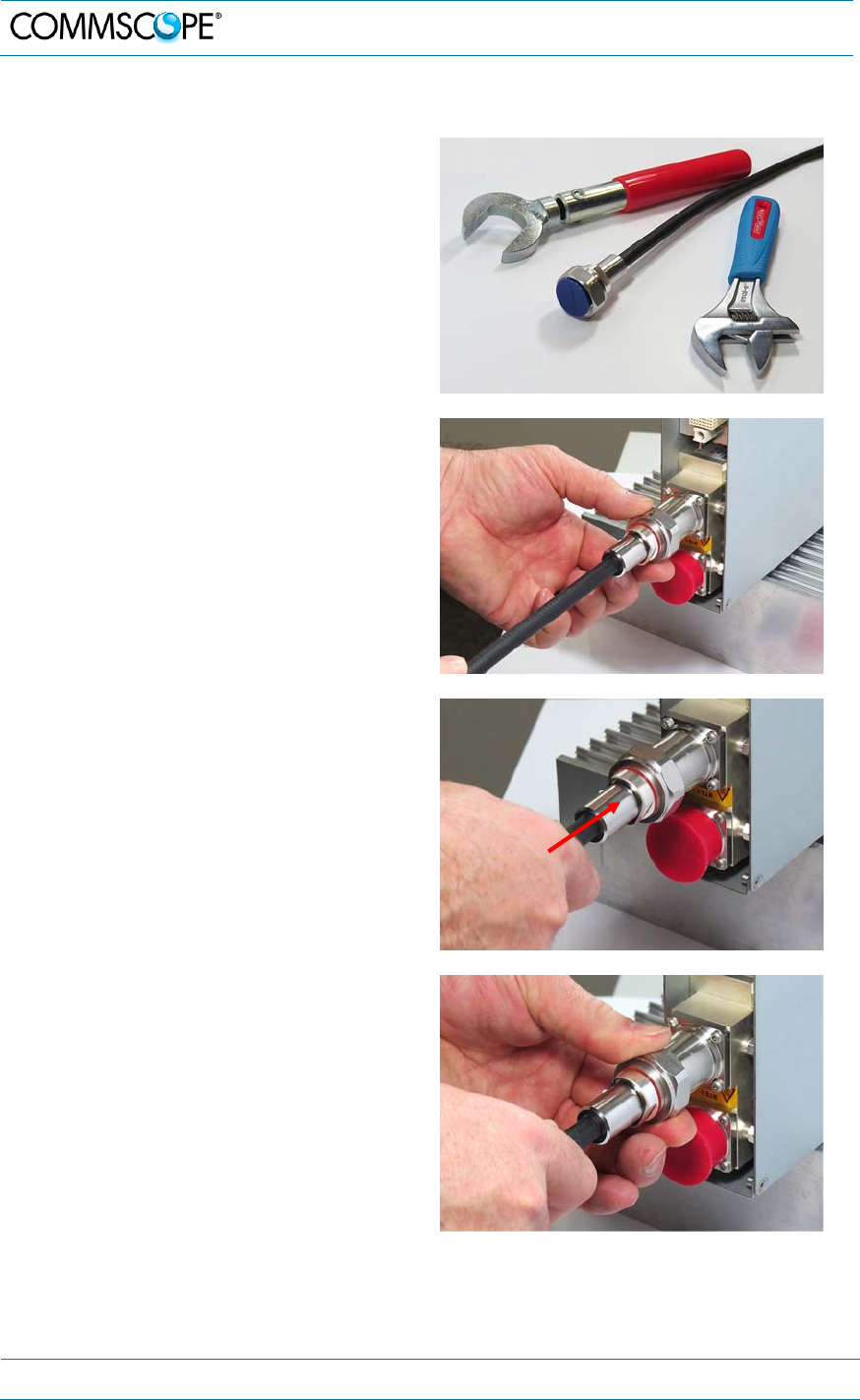
4.2.6.2. Antenna cable connector assembly
1. What is needed for the connector
assembly?
a. Torque wrench.
b. (Adjustable) counter
wrench
2. Join the connectors and turn the
coupling nut until the thread grips.
3. Push in the connector until it clicks.
4. Fasten the coupling nut hand-tight. Do
not turn the connector but the coupling
nut only.
4. Commissioning
MF0200A5C_ION-U_L_7_80-85_17EP_19P.docx Manual for ION
®
-U Page 45
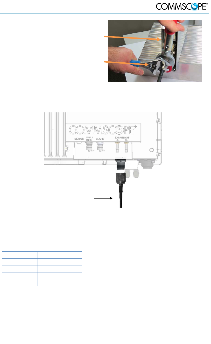
5. Retain the cable connector with the
counter wrench and fasten the
coupling nut with the
torque wrench until the torque is
applied (torque wrench clicks).
For angled antenna connectors use your hand to retain the cable connector and
fasten the coupling nut with the torque wrench. Make sure only the coupling nut is
turned, not the cable connector.
figure 4-23 Antenna connection
4.2.7. Coupling probe
The coupling probe is a QMA measurement probe that allows the measurement of
the antenna output without disconnecting the antenna. The coupling is as follows:
Port Coupling dB typ.
700 MHz 45
800/850 MHz 45
1900 MHz 41
1700 MHz 41
Antenna cable
Torque wrench
Counter wrench
4. Commissioning
Page 46 MF0200A5C_ION-U_L_7_80-85_17EP_19P.docx Manual for ION
®
-U
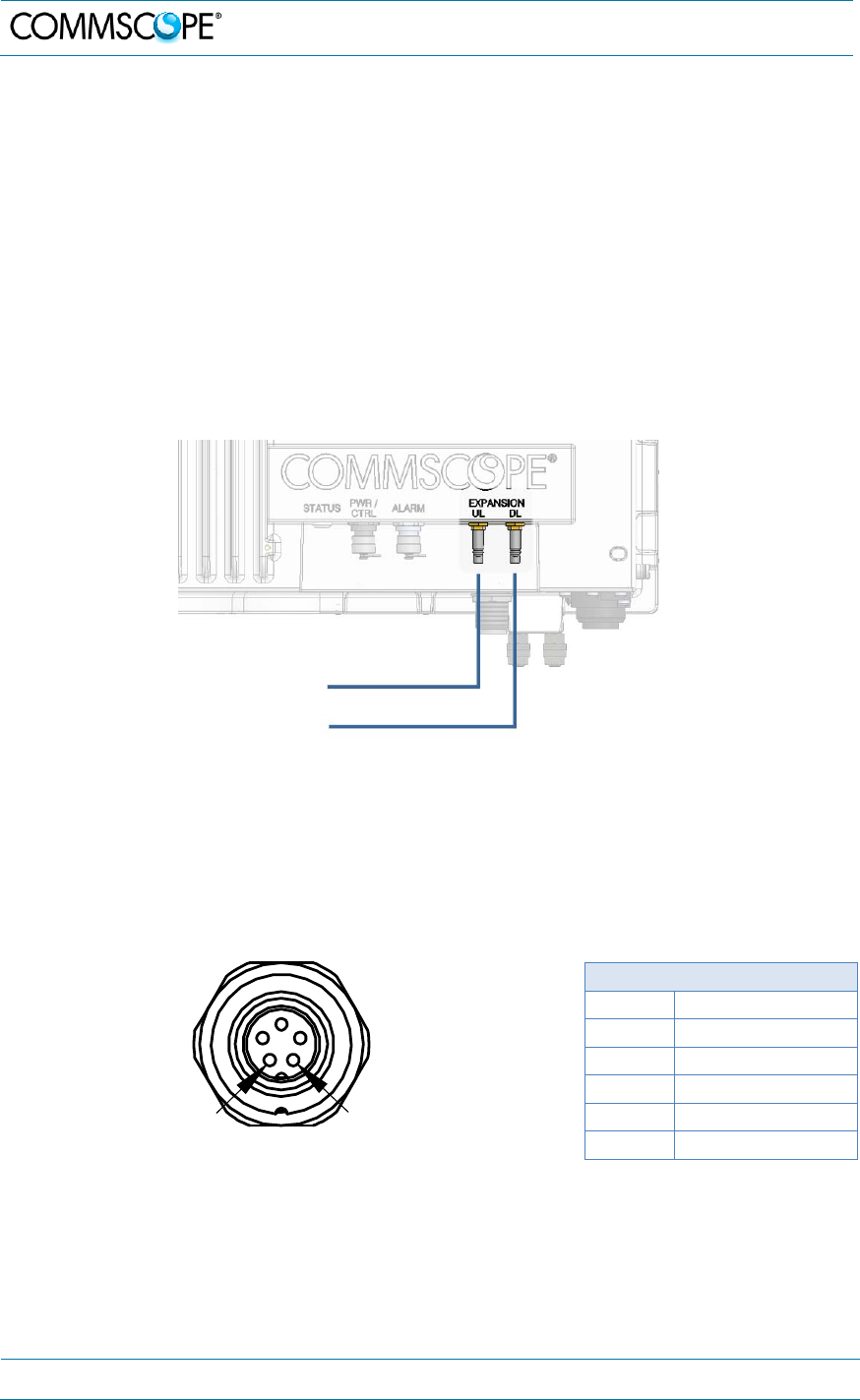
4.2.8. Expansion ports connections
The Expansion ports are QMA-F connectors that are used to connect to an Extension
Unit to provide additional bands of coverage. The cables (1.5 m) required are
included in the EU delivery
1. Connect an RF cable with QMA male connectors between the UL Expansion
port connector of the RU to the UL port of the Extension Unit. Press the QMA
connector of the cable onto the UL port of the RU until it clicks into place to
connect the cable.
2. Connect an RF cable with QMA male connectors between the DL Expansion
port connector of the RU to the DL port of the Extension Unit. Press the QMA
connector of the cable onto the DL port of the RU until it clicks into place to
connect the cable.
figure 4-24 Expansion ports
4.2.9. Alarm port
The Alarm port (RU only) provides alarm contacts that are used to monitor and report
alarms generated by other equipment. The connector is a 5-pin Binder 712 series
connector.
5-Pin Binder 712 Series
Pin Assignment
1 EXT1_Alarm
2 EXT1_GND
3 n.c.
4 EXT2_Alarm
5 EXT_GND
figure 4-25 Alarm connector table 4-6 Alarm connector
51
To Extension unit
UL
DL
4. Commissioning
MF0200A5C_ION-U_L_7_80-85_17EP_19P.docx Manual for ION
®
-U Page 47
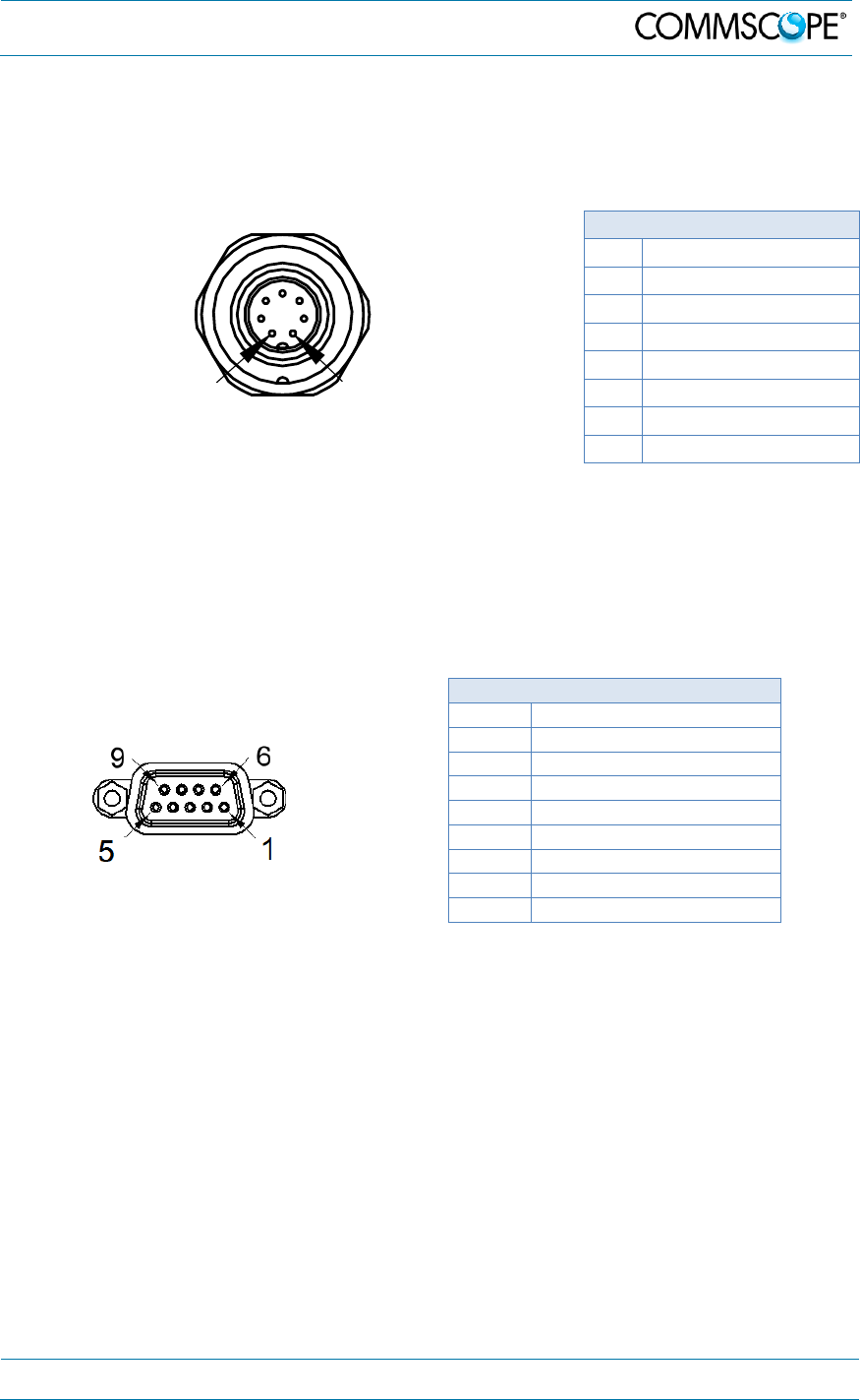
4.2.10. Pwr/Ctrl port
The Pwr/Ctrl port is used to handle an optional fan unit. The connector will provide
power to the fan unit and will allow the RU to control the fan speed. The connector is
a 7-pin Binder 712 series connector.
7-Pin Binder 712 Series
Pin Assignment
1 +V_FAN
2 Fan1 Alarm In
3 Fan1 (PWM) Out
4 GND_FAN
5 Fan2 Alarm In
6 Fan2 (PWM) Out
7 n.c
figure 4-26 Pwr/Ctrl connector table 4-7 Pwr/Ctrl connector
4.2.11. Control connector RS-232 - Local Interface
This DB-9 female connector is used for external modem communication between RU
and EU.
DB-9 Female
PIN
A
ssi
g
nment
1 Not connected (n.c.)
2 RS232 Rx
3 RS232 Tx
4 n.c.
5 GND (RS232)
6 n.c.
7 n.c.
8 n.c.
figure 4-27 RS-232 connector table 4-8 RS-232 connector, pin assignment
Connect the RS-232 cable (1.5 m, contained in delivery of EU) from the LOCAL port
of the RU to the CONTROL port of the EU.
71

4. Commissioning
Page 48 MF0200A5C_ION-U_L_7_80-85_17EP_19P.docx Manual for ION
®
-U
4.3. Low Power RU Optical Installation
4.3.1. Optical-fiber-cable connection - rules
Main optical system parameters:
Fiber:
Single mode fiber, type is 9.5/125 µm
Fiber-cable connectors LC/APC
ION-U system:
Note: The pigtails for the connection between Master Unit and Remote Unit
must have a sufficient length. Protection for the optical fibers must be
provided where the fibers feed into the units.
Note: The system attenuation of the optical fibers, including the connectors,
must not exceed 5 dB.
System attenuation and attenuation of optical components must be determined. This
can be achieved by measuring attenuation with an appropriate measuring instrument.
For pigtails, a total value of < 0.4 dB (measured to a reference plug) can be assumed
due to the dead zone of the reflectometer. These measurements must be made with
a sufficient length of optical fiber, at the input and output of the device which has to
be measured.

4. Commissioning
MF0200A5C_ION-U_L_7_80-85_17EP_19P.docx Manual for ION
®
-U Page 49
Fiber-System Installation:
Fiber-cable connectors have to be of the same type (LC/APC) as the connectors
used for the unit. The fiber-optic cables are connected to the optical transceiver.
Notice: Angled connectors are not compatible with straight optical connectors; non-
compatibility of connectors will result in permanent damage to both connectors.
Before connecting the fiber cables, follow the procedure below to ensure optimized
performance. It is important for these procedures to be carried out with care:
Remove fiber-optic protective caps just before making the fiber connections.
Do not leave any LC/APC connectors open as they may attract dirt. Unused
optical connectors must always be covered by their caps.
Do not bend the fiber-optic cable in a tight radius (< 5 cm) as this may cause
damage to the cable and interrupt transmission.
Using high-grade alcohol and lint-free cotton cleaning swabs, clean the end of
the fiber-optic cable that will be inserted in the optical connectors on the donor
interface box. Use a fiber end-face inspection tool to scan both, the class fiber
and its surrounding area.
Check for dirt on the cladding, chips/pits, dirt on the ferrule, and scratches.
Connect the fiber-optic cables by inserting the cable end into the laser
receptacle.
Do not use any index-matching gels or fluids of any kind in these connectors.
Gels are intended for laboratory use and attract dirt in the field.
Notice: Care should be taken when connecting and disconnecting fiber-optic cables -
use the connector housing to plug or unplug a fiber. Scratches and dust
significantly affect system performance and may permanently damage the
connector. Always use protective caps on fiber-optic connectors not in use.
Cleaning Procedure for Fiber-Optical Components:
Any contamination in the fiber connection results in additional optical transmission
loss which could cause whole system failure. It is thus recommended that every fiber
connector be inspected and cleaned prior to mating.
The goal is to eliminate any dust or contamination and to provide a clean
environment for the fiber-optic connection.
4. Commissioning
Page 50 MF0200A5C_ION-U_L_7_80-85_17EP_19P.docx Manual for ION
®
-U
When you clean fiber components, always complete the following steps carefully:
Caution: Laser radiation. Risk of eye injury in operation. Do not stare into the beam;
do not view it directly or with optical instruments.
1. Turn off the ION-U system (laser sources) before you inspect fiber connectors.
2. Check the connectors or adapters with a fiberscope before cleaning.
3. If the connector is dirty, clean it with a lint-free wipe (dry cleaning).
4. Inspect the connector.
5. If the connector is still dirty, repeat the dry cleaning technique.
6. Inspect the connector.
7. If the connector is still dirty, clean it with 99% isopropyl alcohol (wet cleaning)
followed immediately with a dry clean in order to ensure no residue is left on
the surface.
8. Repeat steps 5 through 7 until surface is clean.
Note: For a more detailed description, please refer to:
http://www.cisco.com/en/US/tech/tk482/tk876/technologies_white_paper09186
a0080254eba.shtml
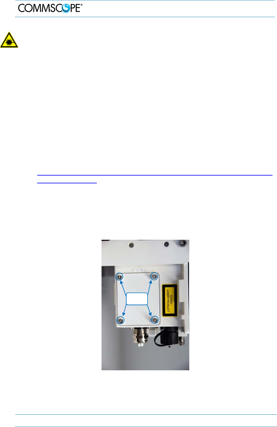
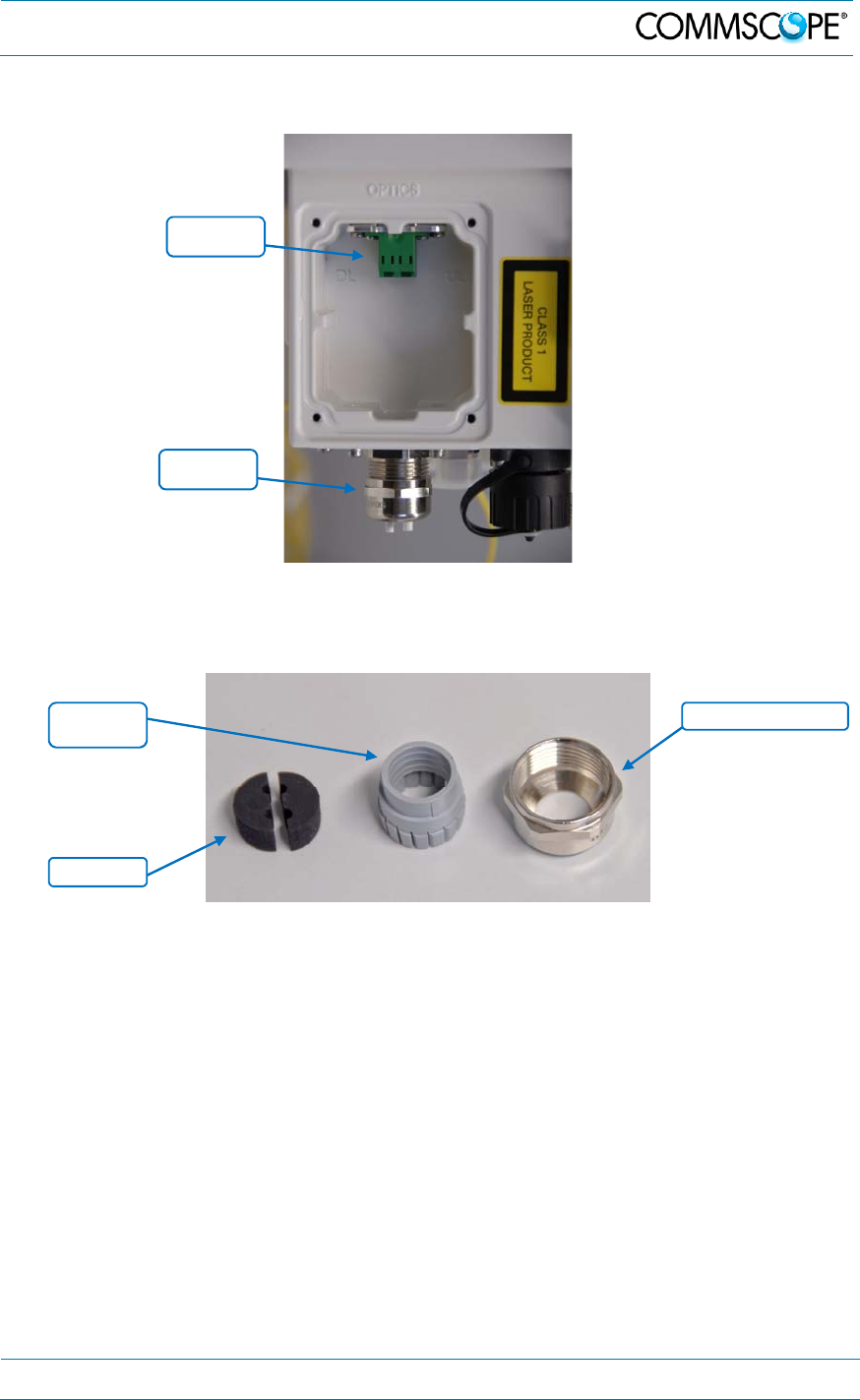
4.3.2. Optical cable installation
Locate the Optics connector cover on the lower right side of the RU. Loosen
the four cover screws, remove the cover, and set it aside. Removing this cover
allows access to the UP and DL optical connectors.
figure 4-28 Remove optics cover
Cover
Sc
r
ews
4. Commissioning
MF0200A5C_ION-U_L_7_80-85_17EP_19P.docx Manual for ION
®
-U Page 51
Remove the sealing nut from the optical cable gland at the bottom of the RU.
figure 4-29 Remove sealing nut
Remove the split-seal and clamp jacket.
figure 4-30 Split-seal and clamp jacket
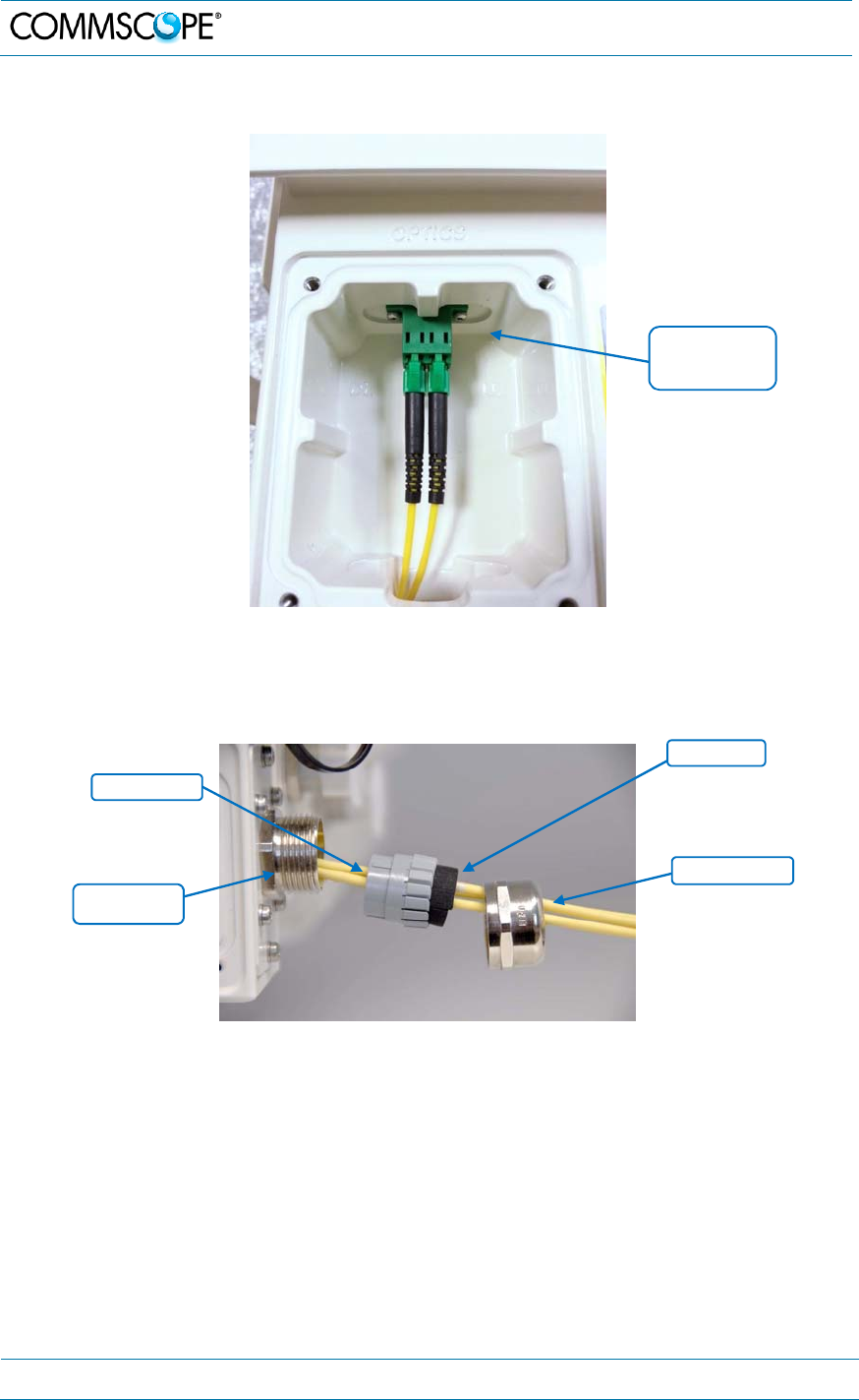
Insert the optical cables through the sealing nut and the clamp jacket.
Then insert the optical cables through the connector socket into the cabinet.
Sealing
nut
Split-seal
Sealing nut
Optical
connectors
Clamp
jacket
4. Commissioning
Page 52 MF0200A5C_ION-U_L_7_80-85_17EP_19P.docx Manual for ION
®
-U
Connect the optical cables to the proper UL and DL LC/APC connectors.
figure 4-31 Optical cables connected
Separate the two halves of the split-seal. Place both cables into the grooves of
each half of the split-seal. Insert the spit seal into the clamp jacket.
figure 4-32 Place cables into split-seal
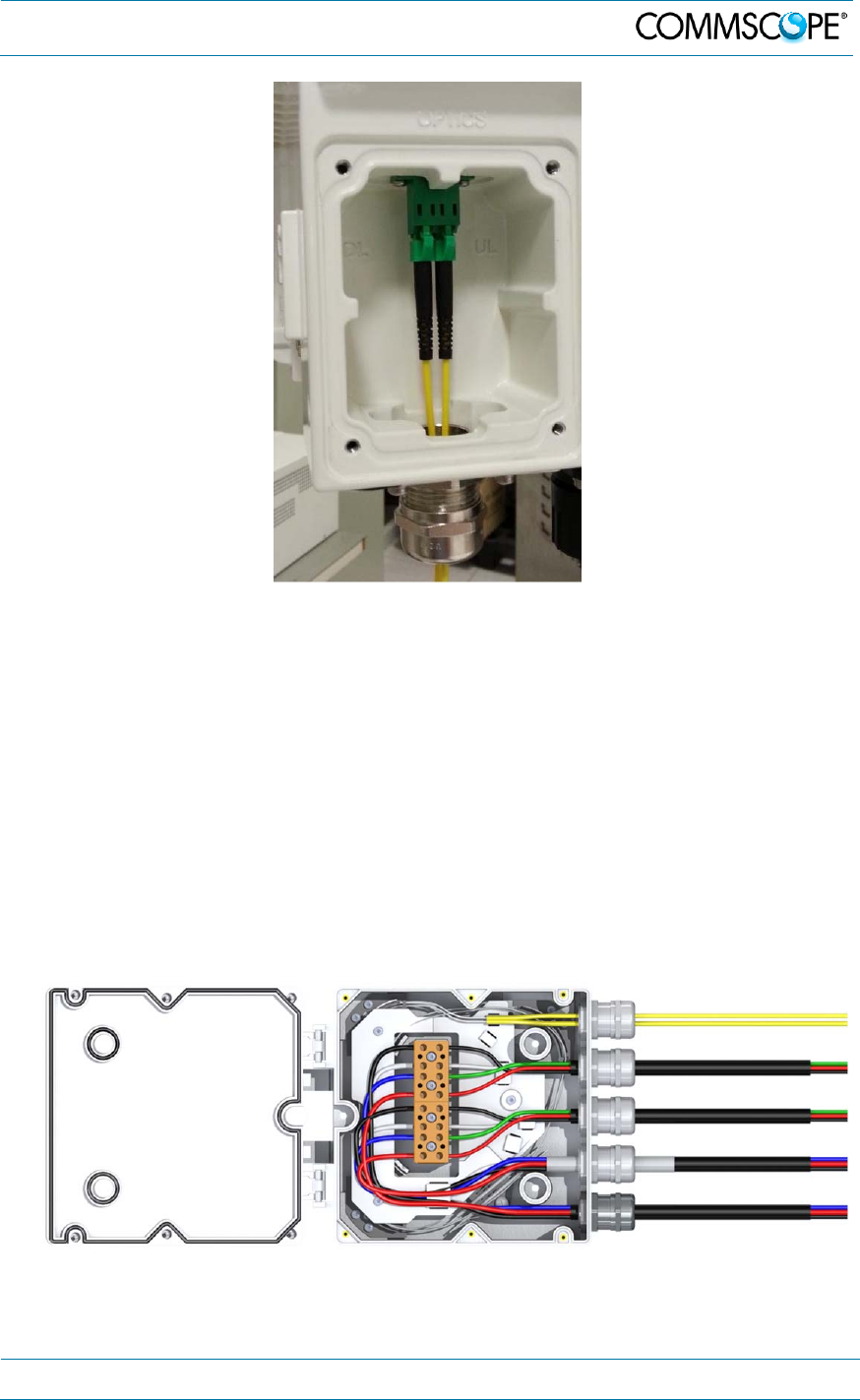
Insert the clamp jacket with split seal to the connector socket and fasten them
with the sealing nut.
Split-seal
Clamp jacket
Connect
LC/APC optical
cables
Sealing nut
Connector
socket
4. Commissioning
MF0200A5C_ION-U_L_7_80-85_17EP_19P.docx Manual for ION
®
-U Page 53
figure 4-33 Optical cable installed
Re-assemble the optics metal cover and tighten the four screws that were
loosened in step 1.
4.4. Accessory Equipment Installation – Splice Box
For the installation and connection of optical and electrical cables a splice box is
available, both for SISO and MIMO installations. The splice box is capable of holding
up to two composite cables (optical and electrical), two electrical cables and four
optic fiber cables.
Attention: To safeguard waterproofness the outer diameter of the optical fibers has
to be 3 mm, the outer diameter of the cables have to be in between 7 to 13 mm.
4. Commissioning
Page 54 MF0200A5C_ION-U_L_7_80-85_17EP_19P.docx Manual for ION
®
-U
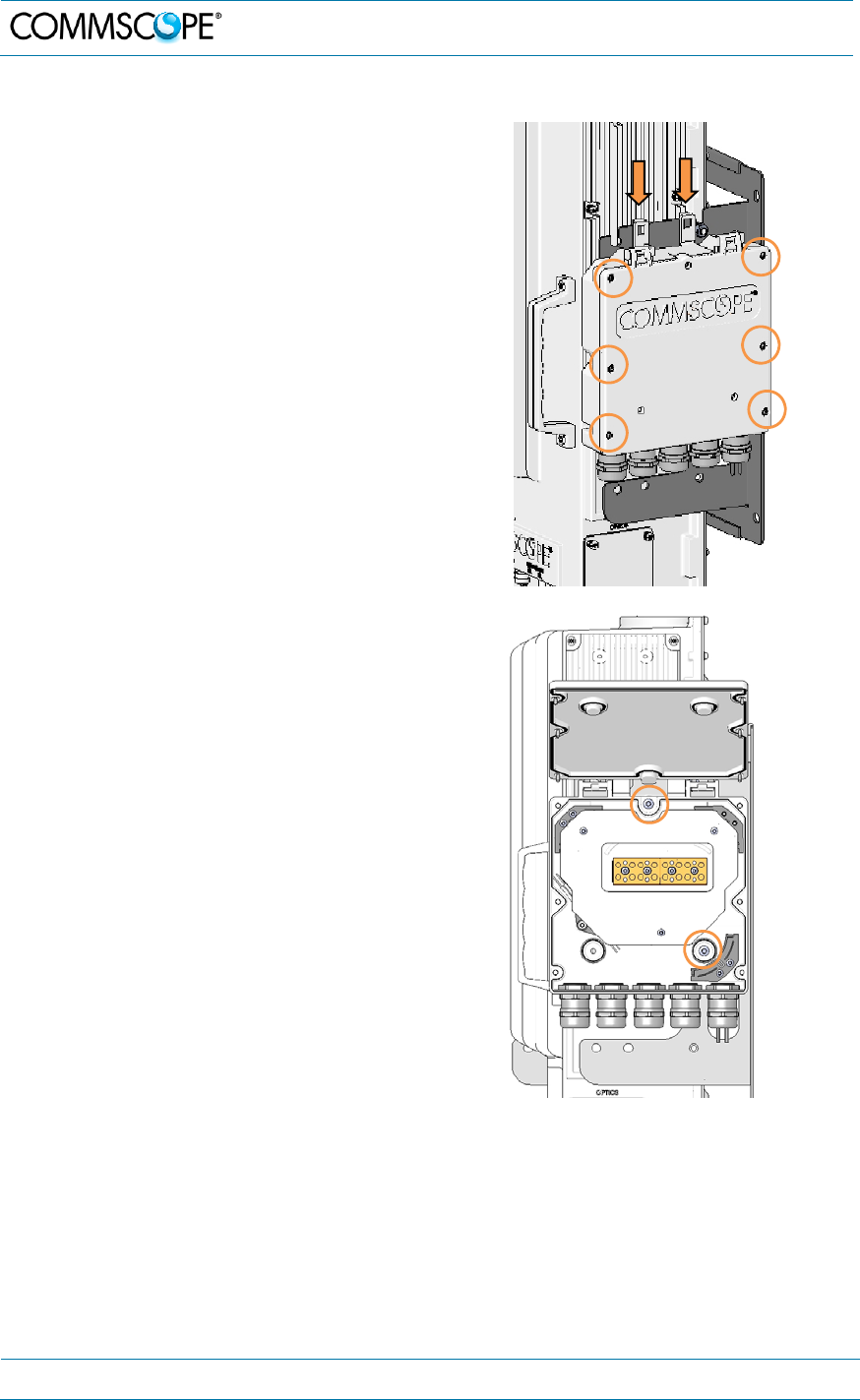
4.4.1. SISO installation
1. Hang the splice box to the mounting
bracket to the right-hand side of the
RU.
2. Open the splice box by unscrewing the
six neck screws.
3. Use the upper hole and the hole to
the right-hand side to fasten the
splice box to the mounting bracket
with two M4 x 25 pan head screws.
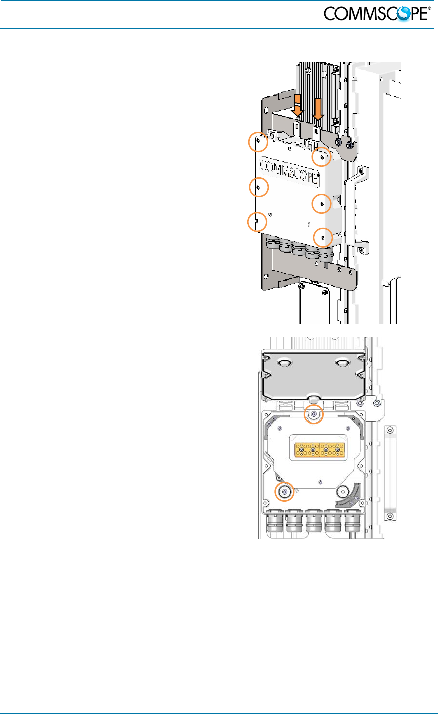
4. Commissioning
MF0200A5C_ION-U_L_7_80-85_17EP_19P.docx Manual for ION
®
-U Page 55
4.4.2. MIMO installation
1. First break the left-hand side hook of
the splice box bracket. This is
necessary for proper mounting.
2. Hang the splice box to the mounting
bracket to the left-hand side of the
RUs.
3. Open the splice box by unscrewing the
six neck screws.
4. Use the upper hole and the hole to the
left-hand side to fasten the splice box
to the mounting bracket with two M4 x
25 pan head screws.
4. Commissioning
Page 56 MF0200A5C_ION-U_L_7_80-85_17EP_19P.docx Manual for ION
®
-U
4.5. Low Power RU Alarms
4.5.1. Bite and alarms
The Built-In Test concept comprises the monitoring of the power supplies, the power
amplifiers, and the optical interface.
All alarms that occur can be checked via software at the Master Unit.
4.5.2. Handling of alarms
As soon as the software acknowledges a valid alarm, a message is transmitted to the
master unit.
If the reason for the alarm has been cleared or if the alarm should continue, a new
alarm message will not be repeated. If there is an interruption of at least five seconds
after acknowledgement, a new alarm message will be generated.
figure 4-34 Alarm triggering
clear
Alarm LED
Alarm transmit
Alarm cause
raise
> 5 s < 5 s
raise
> 5 s
clear

4. Commissioning
MF0200A5C_ION-U_L_7_80-85_17EP_19P.docx Manual for ION
®
-U Page 57
4.5.3. Status LED alarms
For local supervision, a status LED on the connector panel of the Remote Unit
adjacent to the Expansion ports provides a visual warning of an alarm condition. The
color of the LED indicates the severity of the alarm. Detailed alarm information is
available through the ION-U software interface. This table lists the alarm conditions
and possible on-site measures that could be performed to resolve the issues
responsible for triggering the alarms.
Alarm Name Description Remedy Default
Severity LED
DL optical power fail Received optical power
below minimum threshold check fiber connections and
transmitted optical power major Red
Temperature Alarm temperature too high check ventilation and environment warning Green
VSWR Alarm bad RF cabling /
mismatched antenna check cable / antenna critical Orange
RF Low Output
CELL700 RF signal too low check BTS output level/attenuator
configuration/RF cabling minor Green
RF Low Output CELL
850 RF signal too low check BTS output level/attenuator
configuration/RF cabling minor Green
RF Low Output LMR
800 RF signal too low check BTS output level/attenuator
configuration/RF cabling minor Green
RF Low Output PCS
1900E RF signal too low check BTS output level/attenuator
configuration/RF cabling minor Green
RF Low Output AWS RF signal too low check BTS output level/attenuator
configuration/RF cabling minor Green
DL CELL 700 band
alarm hw failure in RF section change unit critical Red
DL LMR800+CELL850
alarm hw failure in RF section change unit critical Red
DL PCS 1900E band
alarm hw failure in RF section change unit critical Red
DL AWS band alarm hw failure in RF section change unit critical Red
UL CELL 700 band
alarm hw failure in RF section change unit critical Red
UL LMR800+CELL850
band alarm hw failure in RF section change unit critical Red
UL PCS 1900E band
alarm hw failure in RF section change unit critical Red
UL AWS band alarm hw failure on RF section change unit critical Red
UL Overdrive/ALC
Limiting CELL 700 too high RF signal feeding
device check unit/attenuator configuration minor Green
UL Overdrive/ALC
Limiting
LMR800+CELL850
too high RF signal feeding
device check unit/attenuator configuration minor Green
UL Overdrive/ALC
Limiting PCS 1900E RF signal feeding device
too high check unit/attenuator configuration minor Green
UL Overdrive/ALC
Limiting AWS RF signal feeding device
too high check unit/attenuator configuration minor Green
Internal bus alarm internal I2CBUS
communication malfunction change unit critical Red
UL Laser Alarm Uplink laser fail (cooling or
current failure) change unit major Red

4. Commissioning
Page 58 MF0200A5C_ION-U_L_7_80-85_17EP_19P.docx Manual for ION
®
-U
Alarm Name Description Remedy Default
Severity LED
External 1 Alarm external input alarm check external device/ check alarm
connection major Orange
External 2 Alarm external input alarm check external device/ check alarm
connection major Orange
RF High Output
CELL700 RF signal too high check BTS output level/attenuator
configuration/RF cabling major Green
RF High Output CELL
850 RF signal too high check BTS output level/attenuator
configuration/RF cabling major Green
RF High Output LMR
800 RF signal too high check BTS output level/attenuator
configuration/RF cabling major Green
RF High Output PCS
1900E RF signal too high check BTS output level/attenuator
configuration/RF cabling major Green
RF High Output AWS RF signal too high check BTS output level/attenuator
configuration/RF cabling major Green
Power Supply 1 Alarm internal power supply
alarm change/verify unit major Red
Power Supply 2 Alarm internal power supply
alarm change/verify unit major Red
Power Supply 1
exceeded load
threshold power supply load too high change/verify unit minor Green
Power Supply 2
exceeded load
threshold power supply load too high change/verify unit minor Green
Power Supply 1 partial
availability
internal power supply
alarm / partial power
available change/verify unit major Green
Power Supply 2 partial
availability
internal power supply
alarm / partial power
available change/verify unit major Green
High Power
Consumption power supply load too high change/verify unit minor Green
Low Power
Consumption power supply load too low change/verify unit minor Green
table 4-9 Status LED alarms
4.6. External Alarm Inputs
With the external alarm inputs, it is possible to monitor the status of connected
devices, e.g. a UPS, via software. All alarm inputs are normally high (5 V) without
connection. The polarity (high/ low) can be set via the software at the Master Unit (for
details please see the appropriate ION-U software manual).
The device to be monitored must be connected so that the alarm contacts will be
closed in case of an alarm (I max = 8 mA). The alarm inputs are potential-free with
common ground (earth).
Subminiature circular connectors series 712 with five contacts, which are contained
in the alarm kit, can be ordered directly from the Binder Connector Group, the
manufacturer, or indirectly from CommScope.

5. Low Power RU Maintenance
MF0200A5C_ION-U_L_7_80-85_17EP_19P.docx Manual for ION
®
-U Page 59
4.7. Troubleshooting
The status of the Remote Unit can be checked via the master unit (for details please
refer to the ION-U software manual). Locally, the status can be checked at the LED,
see chapter 4.5.3 Status LED alarms.
5. Low Power RU Maintenance
5.1. General
Read and observe chapter 1.2 Health and Safety.
Note: The Remote Unit does not require preventative maintenance measures.
Maintenance of the ION-U Low Power units should be performed by replacing only
components that are described in this chapter. In order to maintain the warranty,
avoid unintentional damage to the seals on the modules.
The spare parts list includes only units that can be replaced in the field without tuning
or soldering work.
Please contact your CommScope sales representative or DCCS Technical Support
for a current ION-U LP RU parts list.
Note: When sending back the unit, use appropriate packaging. Use of the
original packaging for shipping the unit is strongly recommended.
Note: Defective parts should only be replaced by original parts from the
supplier. All service work performed inside the housing is performed at
the users own risk.
Note: Label any unlabelled cables before disconnecting them to ensure
correct reconnection.
Unless otherwise agreed to in writing by CommScope, CommScope’s general limited
product warranty (http://www.commscope.com/Resources/Warranties/) shall be the
warranty governing the Remote Units, including the installation, maintenance, usage
and operation of the Remote Units.
For most maintenance procedures, appropriate tools are required to ensure correct
handling. All of these tools can be ordered from the supplier.
Note: All unit screws have a right-hand thread, and are tightened by turning
the screws clockwise and loosened by turning them counter-clockwise
with an appropriate tool.
Due to the design of the Remote Unit, the power supply is the only component that
should be replaced in the field. Please contact the supplier for replacement of any
other components.
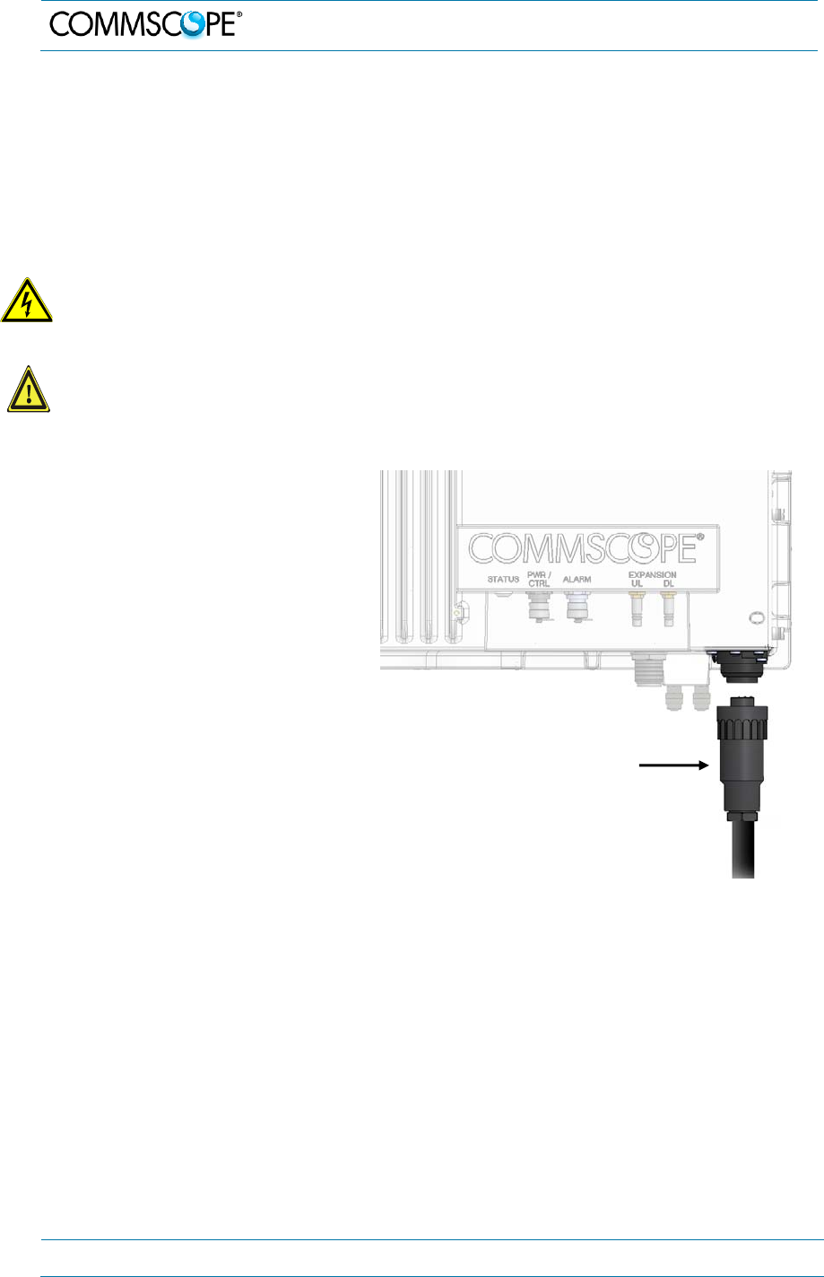
5. Low Power RU Maintenance
Page 60 MF0200A5C_ION-U_L_7_80-85_17EP_19P.docx Manual for ION
®
-U
5.2. RU Power Supply Replacement
The power supply for the RU is a field replaceable module. The type of power supply
used by the unit (AC, DC, or Vdc/100) is dependent on the model number.
Attention: Before starting any maintenance on the RU, read and observe
chapter 1.2
Health and Safety and the electrical installation information in chapter 4.2.1
Health and Safety for electrical installation.
1. Danger: Electrical hazard. Danger of death or fatal injury from electrical
current inside the unit in operation. Before opening the unit, disconnect
mains power.
2. Caution: The unit reaches high temperature in operation. Risk of burns by
hot surface. Do not touch the unit before it has sufficiently cooled down.
1. Switch off the circuit breaker
supplying power to the RU.
2. Once you have confirmed that
the power has been shutdown,
remove Mains power
connector from the unit.
figure 5-1 Disconnect mains power
Mains plug
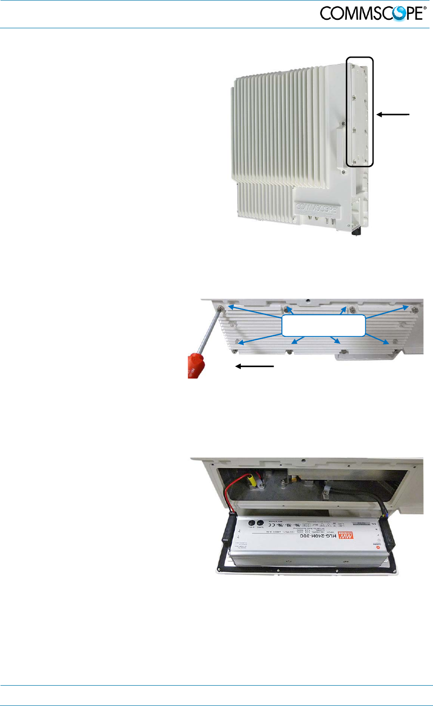
5. Low Power RU Maintenance
MF0200A5C_ION-U_L_7_80-85_17EP_19P.docx Manual for ION
®
-U Page 61
3. Locate the power supply on
the right side of the Remote
Unit.
figure 5-2 RU power supply location
4. Use a #2 Phillips head or
slotted screwdriver to loosen
the 8 universal slot/Phillips
captive power supply screws
and carefully remove the
supply. The weight of the
power supply must be
supported as you loosen the
screws to prevent damage to
the supply.
figure 5-3 8 RU power supply screws
5. Carefully remove the power
supply from the unit. Do not
attempt to support the weight
of the supply with the attached
input and output cables.
figure 5-4 RU power supply with cables
Mains
connecto
r
Power
supply
Loosen 8 universal
slot/Phillips screws
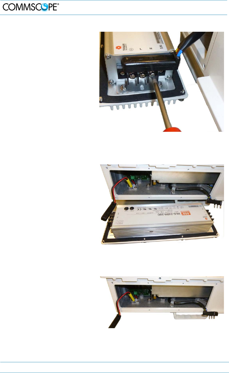
5. Low Power RU Maintenance
Page 62 MF0200A5C_ION-U_L_7_80-85_17EP_19P.docx Manual for ION
®
-U
6. Locate the input cable
connector for the power
supply on the right side of the
supply.
7. Loosen the 3 Phillips head
terminal screws and remove
the connector.
figure 5-5 RU power supply input cable
8. Locate the output connector
for the power supply on the
left side of the supply.
9. Loosen the 2 Phillips head
screws and remove the output
connector.
figure 5-6 RU power supply output cable
10. Remove the defective supply.
figure 5-7 RU with power supply removed
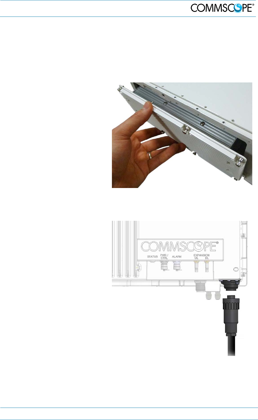
5. Low Power RU Maintenance
MF0200A5C_ION-U_L_7_80-85_17EP_19P.docx Manual for ION
®
-U Page 63
11. Replace the defective power supply with the new power supply.
It is very important to confirm that the replacement supply is the same type as the
original supply. The AC, DC, and Vdc/100 supplies are not interchangeable.
12. Reconnect the input and output connectors, and tighten the associated terminal
screws.
13. Insert the power supply into
the RU carefully to avoid
damaging any cables. The
supply must be supported until
the 8 universal slot/Phillips
captive power supply screws
have been tightened.
14. Tighten the 8 universal
slot/Phillips captive power
supply screws.
figure 5-8 RU insert power supply
15. Reconnect the Mains power
plug.
16. Switch on the breaker and
check the RU for proper
operation.
figure 5-9 Reconnect mains power
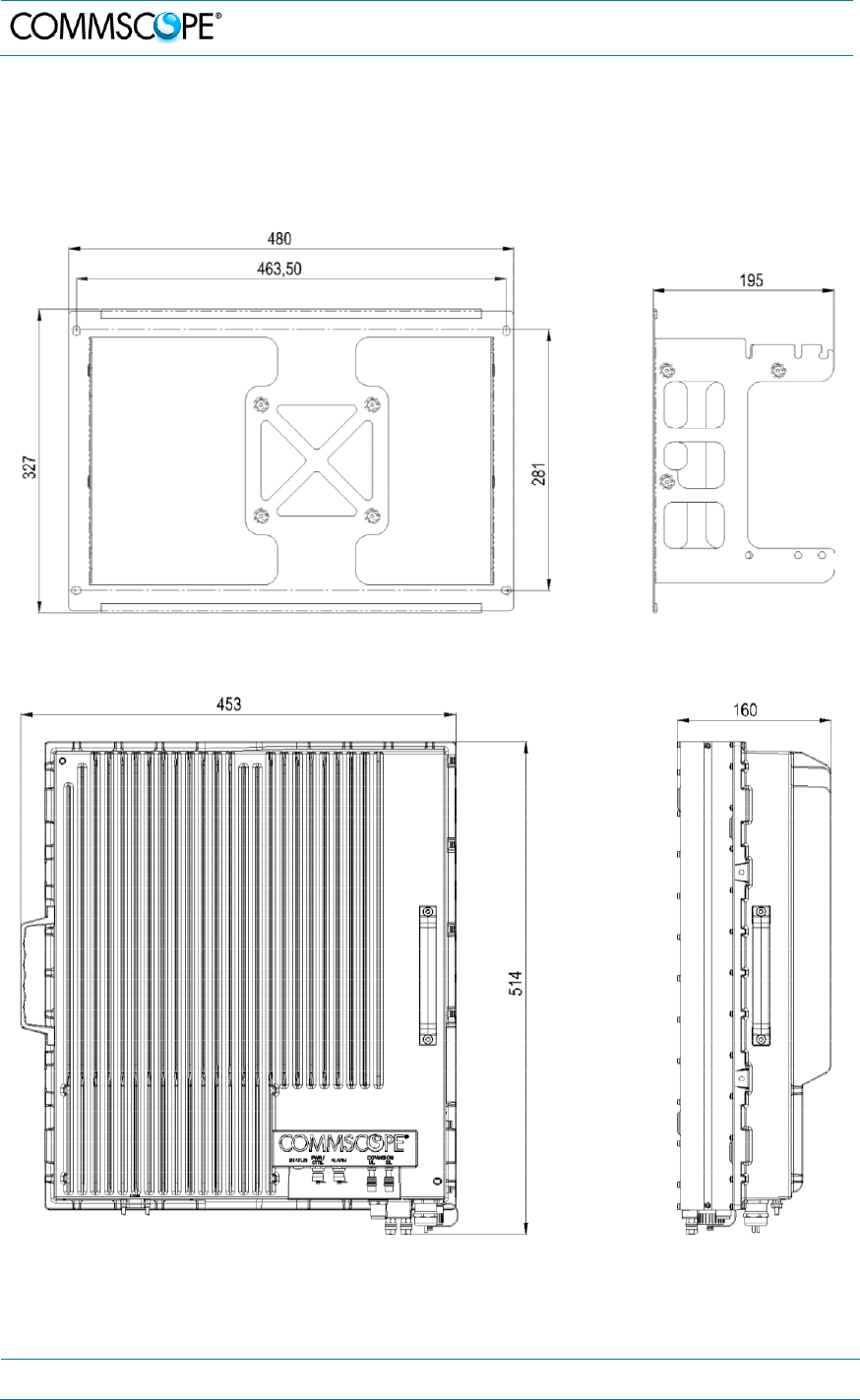
6. Appendix
Page 64 MF0200A5C_ION-U_L_7_80-85_17EP_19P.docx Manual for ION
®
-U
6. Appendix
6.1. Illustrations
figure 6-1 ION-U Low Power RU mounting bracket
figure 6-2 ION-U Low Power Unit dimensions
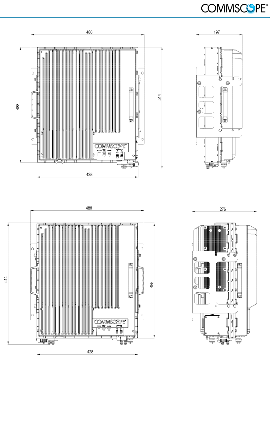
6. Appendix
MF0200A5C_ION-U_L_7_80-85_17EP_19P.docx Manual for ION
®
-U Page 65
figure 6-3 Installation drawing of ION-U L Unit SISO
figure 6-4 Installation drawing of ION-U L Unit MIMO

7. List of Changes
Page 66 MF0200A5C_ION-U_L_7_80-85_17EP_19P.docx Manual for ION
®
-U
6.2. Specifications
This manual is valid for the following Remote Unit:
ID No Denomination
7669582-xxxx* ION-U L 7/80-85/17P/19P
7669582-0001 ION-U L 7/80-85/17P/19P-VAC
7669582-0002 ION-U L 7/80-85/17P/19P-VDC
7669582-0003 ION-U L 7/80-85/17P/19P-VDC/100
7669582-0007 ION-U L 7/80-85/17EP/19P-VAC
7669582-0008 ION-U L 7/80-85/17EP/19P-VDC
7669582-0009 ION-U L 7/80-85/17EP/19P-VDC/100
* The xxxx suffix is the identifier for the specific configuration of the Remote Unit.
Please refer to the ION-U_LP_RU_US_PA-106156.X-EN.GB data sheets or our
e-catalog http://www.commscope.com/catalog for the ION-U LP RU specifications.
6.3. Spare Parts
Maintenance of the RU should be performed on an FRU (Field Replaceable Unit)
basis only. If any FRU not contained in the following list needs to be replaced, please
contact customer service for additional instructions.
Designation: ID No
Splice box 7693816-xx
Power Supply Unit Vac RPS150-Vac 7658962-xx
Power Supply Unit Vdc RPS150-Vdc 7658963-xx
Power Supply Unit Vdc 100 RPS150-Vdc/100 7662384-xx
The manufacturer reserves the right to replace the spare parts listed above by
equivalent substitutes.
Note: Only the spare parts listed above are FRUs and can be replaced by the
user. For replacement of any other parts, please send the entire
Remote Unit back to the manufacturer.
7. List of Changes
Version Changes Release Date
M0200A5B 28-October-2015
M0200A5C - added ION-U L 7/80-85/17EP/19P
- chapters 3.3 and 4.2.3 updated,
- chapter 4.2.7 added, antenna probe
- chapter 4.3.1 updated, optical
measurement
- chapter 6.3 added, spare parts
Not yet released

8. Index
MF0200A5C_ION-U_L_7_80-85_17EP_19P.docx Manual for ION
®
-U Page 67
8. Index
A
Alarm ...................................................................... 35
Alarm port ............................................................... 46
Alarms
Bite and Alarms ................................................. 56
External Inputs .................................................. 58
Handling of Alarms ............................................ 56
Status LED ........................................................ 57
Ant RF .................................................................... 35
B
Block Diagram
ION-U L 7/80-85/17(E)P/19P RU ...................... 17
C
CE Declaration of Conformity (DoC) ...................... 13
Commissioning
General .............................................................. 21
CommScope ........................................................... 13
Compliance .............................................................. 9
Connection Rules
Optical-Fiber Cables ......................................... 48
Connections
Antenna ....................................................... 39, 40
Power ................................................................ 37
Connectors
Alarm connector ................................................ 20
Mains connector ................................................ 20
Pwr/Ctrl connector ............................................. 20
Contact Addresses, Customer Support ........... 14, 15
Coupling Port.......................................................... 45
E
Expansion DL ......................................................... 35
Expansion ports ..................................................... 46
Expansion UL ......................................................... 35
F
Fiber-Optical Components
Cleaning Procedure .......................................... 49
System Installation ............................................ 49
G
Grounding (Earthing).............................................. 36
Grounding Bolts ..................................................... 35
H
Health and Safety ..................................................... 8
I
Illustrations ............................................................. 64
Installation
Electrical ........................................................... 33
Mechanical ........................................................ 21
ION-U LP RU Ports ............................................... 19
M
Mains (Vac/Vdc) .................................................... 35
Mains (Vdc/100) ..................................................... 35
Mains connector .................................................... 37
Maintenance .......................................................... 59
Mechanical installation
Mounting bracket .............................................. 22
Threaded pins ................................................... 25
MIMO applications ................................................. 18
Mounting bracket
To a pole ........................................................... 23
To a wall ............................................................ 22
O
Optical cable installation ........................................ 50
Optics DL ............................................................... 35
Optics UL ............................................................... 35
P
Ports
Antenna Port ..................................................... 20
Expansion Ports ................................................ 20
Optical Ports ..................................................... 20
RS-232 port ....................................................... 20
Property Damage Warnings .................................... 8
PWR/CTRL ............................................................ 35
R
RS-232 ................................................................... 35
RU AC power cable ............................................... 37
RU DC power cable ............................................... 37
RU Power Supply Replacement ............................ 60
RU Vdc/100 power cable ....................................... 38
S
SISO applications .................................................. 18
Spare Parts ...................................................... 59, 66
Splice box installation ............................................ 53
Status ..................................................................... 35
T
Troubleshooting ..................................................... 59