Andrew Wireless System UEUH19P2 ION-U Remote Unit for cellular systems User Manual
Andrew Wireless System ION-U Remote Unit for cellular systems
Contents
- 1. installation manual
- 2. user manual
user manual
DRAFT
ION®-U
EU H 19P2 Extension Unit
User's Manual
MF0200A0A

Page 2 7.Manual MF0200A0A ION-U_EU H 19P2_uc_08-July-13.docx
User
’
s Manual for ION
®
U
DISCLAIMER:
This document has been developed by CommScope, and is intended for the use of its
customers and customer support personnel. The information in this document is subject to
change without notice. While every effort has been made to eliminate errors, CommScope
disclaims liability for any difficulties arising from the interpretation of the information
contained herein. The information contained herein does not claim to cover all details or
variations in equipment, nor to provide for every possible incident to be met in connection
with installation, operation, or maintenance. This document describes the performance of the
product under the defined operational conditions and does not cover the performance under
adverse or disturbed conditions. Should further information be desired, or should particular
problems arise which are not covered sufficiently for the purchaser’s purposes, contact
CommScope.
CommScope reserves the right to change all hardware and software characteristics without
notice.
COPYRIGHT:
© Copyright 2013 CommScope Inc. All Rights Reserved.
This document is protected by copyright. No part of this document may be reproduced,
stored in a retrieval system, or transmitted, in any form or by any means, electronic,
mechanical photocopying, recording, or otherwise without the prior written permission of
CommScope.
TRADEMARKS
All trademarks identified by ® or ™ are registered trademarks or trademarks, respectively, of
CommScope. Names of products mentioned herein are used for identification purposes only
and may be trademarks and / or registered trademarks of their respective companies.
Andrew Wireless Systems GmbH, 08-July-2013

Table of contents
7.Manual MF0200A0A ION-U_EU H 19P2_uc_08-July-13.docx
User
’
s Manual for ION
®
U
Page 3
TABLE OF CONTENTS
1.
GENERAL 6
1.1.USED ABBREVIATIONS 6
1.2.HEALTH AND SAFETY WARNINGS 7
1.3.ABOUT COMMSCOPE 10
1.4.INTERNATIONAL CONTACT ADDRESSES FOR CUSTOMER SUPPORT 11
2.
INTRODUCTION 14
2.1.PURPOSE 14
2.2.ION-U HIGH POWER REMOTE AND EXTENSION UNITS 14
3.
FUNCTIONAL DESCRIPTION 15
3.1.1.Fan Protection Kit 15
3.1.2.Accessories 15
4.
COMMISSIONING 16
4.1.HIGH POWER RU MECHANICAL INSTALLATION 16
4.1.1.General 16
4.1.2.Wall-Mounting Procedure 18
4.1.3.Pole Mounting Procedure 19
4.1.4.Mounting of Fan Protection 20
4.2.ELECTRICAL INSTALLATION 22
4.2.1.General 22
4.2.2.Connections 23
4.2.3.Grounding (Earthing) 25
4.2.4.Connection of the Antenna Cable 25
4.2.5.Mains Power Connection 27
4.2.6.Extension Unit Port Connection 28
4.3.COMMISSIONING 30
5.
ALARMS 33
5.1.BITE AND ALARMS 33
5.2.HANDLING OF ALARMS 33
5.3.ALARM STATUS 33
5.4.STATUS LED ALARMS 33
5.5.TROUBLESHOOTING 35

Table of contents
Page 4 7.Manual MF0200A0A ION-U_EU H 19P2_uc_08-July-13.docx
User
’
s Manual for ION
®
U
6.
MAINTENANCE 36
6.1.GENERAL 36
6.2.REPLACING THE FAN UNIT 37
6.3.CLEANING THE HEAT SINK 39
7.
APPENDIX 40
7.1.ILLUSTRATIONS 40
7.2.SPECIFICATIONS 43
7.3.SPARE PARTS 43
8.
INDEX 44

figures and tables
7.Manual MF0200A0A ION-U_EU H 19P2_uc_08-July-13.docx
User
’
s Manual for ION
®
U
Page 5
FIGURES AND TABLES
figure 3-3 Shroud with RU and EU ............................................................................. 15
figure 4-1 Wall Mounting ............................................................................................. 18
figure 4-2 Pole mounting kit ........................................................................................ 19
figure 4-3 Pole mounting drawing ............................................................................... 20
figure 4-4 Mounting procedure for fan protection ....................................................... 21
figure 4-5 ION-U H 17P2 Connectors ......................................................................... 23
figure 4-6 Grounding bolt ............................................................................................ 25
figure 4-7 Grounding bolt, schematic view ................................................................. 25
figure 4-8 Antenna port to CBC wiring ........................................................................ 26
figure 4-9 Mains power connector .............................................................................. 27
figure 4-10 Mains power cable - AC ........................................................................... 28
figure 4-11 EU (Extension Unit) connector ................................................................. 28
figure 4-12 Extension unit cable bridge ...................................................................... 29
figure 5-1 Alarm triggering .......................................................................................... 34
figure 7-1 Installation drawing-front and rear views ................................................... 40
figure 7-2 Installation drawing-side views ................................................................... 41
figure 7-3 Installation drawing-short version .............................................................. 42
table 1-1 List of international contact addresses ........................................................ 13
table 4-1 Specified torques ......................................................................................... 17
table 4-2: ION-U High Power EU Connectors ............................................................ 24
table 4-3 AC power cable ........................................................................................... 28
table 4-4 EU Connector .............................................................................................. 28
table 5-1 Status LED alarms ....................................................................................... 34

1. General
Page 6 7.Manual MF0200A0A ION-U_EU H 19P2_uc_08-July-13.docx
User
’
s Manual for ION
®
U
1. General
1.1. Used Abbreviations
AC/DC Alternating current / Direct Current
AIMOS Andrew Integrated Management and Operating System
ALC Automatic Level Control
BITE Built-In Test Equipment
BTS Base Transceiver Station
CDMA Code Division Multiple Access
CE "Conformité Européenne" ("European Conformity")
CPD Channel Power Detection
DL Downlink
DoC Declaration of Conformity
dSMR Measurement Receiver
EP Extension Port
ESD Electrostatic Discharge
EU Extension Unit
GSM Global System for Mobile Communication
GND Ground (Earth)
GUI Graphical User Interface
ICP3 Intercept Point 3rd order
ID No Identification Number
IFC Interface Card
ION Intelligent Optical Network
LED Light Emitting Diode
LMT Local Maintenance Terminal
LTE Long Term Evolution
MIMO Multiple Input Multiple Output
MS Mobile Station
MU Main Unit
NF Noise Figure
OMC Operations and Maintenance Center
OTRx Optical Transceiver = SRMU (Subrack Master Unit)
PDU Power Distribution Unit
PIM Passive Intermodulation
Pin Input power
Pout Output power
PSU Power Supply Unit
Rev Revision
RF Radio Frequency
RU Remote Unit
RX Receiver
SISO Single Input Single Output
SM Site Manager
SMTX Sector Matrix Module
SNMP Simple Network Management Protocol
SRC Subrack Controller
TX Transmitter
UL Uplink
UMTS Universal Mobile Telecommunication System
UPS Uninterruptible Power Supply
VSWR Voltage Standing Wave Ratio
WCDMA Wideband Code Division Multiple Access
WDM Wavelength Division Multiplex
XML Extensible Markup Language
ZCMB Zone Combiner Module
1. General
7.Manual MF0200A0A ION-U_EU H 19P2_uc_08-July-13.docx
User
’
s Manual for ION
®
U
Page 7
1.2. Health and Safety Warnings
1. Danger: Obey all general and regional installation and safety regulations relating
to work on high voltage installations, as well as regulations covering correct use
of tools and personal protective equipment.
2. Danger: Laser radiation! Do not stare into the beam; do not view it directly or with
optical instruments.
3. Danger: Before opening the unit, disconnect mains power.
4. Danger: Due to power dissipation, the remote unit may reach a very high
temperature. Do not operate this equipment on or close to flammable materials.
Use caution when servicing the unit.
5. Warning: Read and obey all the warning labels attached to the unit. Make sure
that all warning labels are kept in a legible condition. Replace any missing or
damaged labels.
6. Warning: It is the responsibility of the network provider to implement prevention
measures to avoid health hazards associated with radiation from the antenna(s)
connected to the unit.
7. Warning: Make sure, access is restricted to qualified personnel.
8. Warning: Only license holders for the respective frequency range are allowed to
operate this unit.
9. Warning: Make sure the repeater settings are correct for the intended use (refer
to the manufacturer product information) and regulatory requirements are met.
10. Warning: Use this equipment only for the purpose specified by the manufacturer.
Do not carry out any modifications or fit any spare parts, which are not sold or
recommended by the manufacturer. This could cause fires, electric shock, or
other injuries.
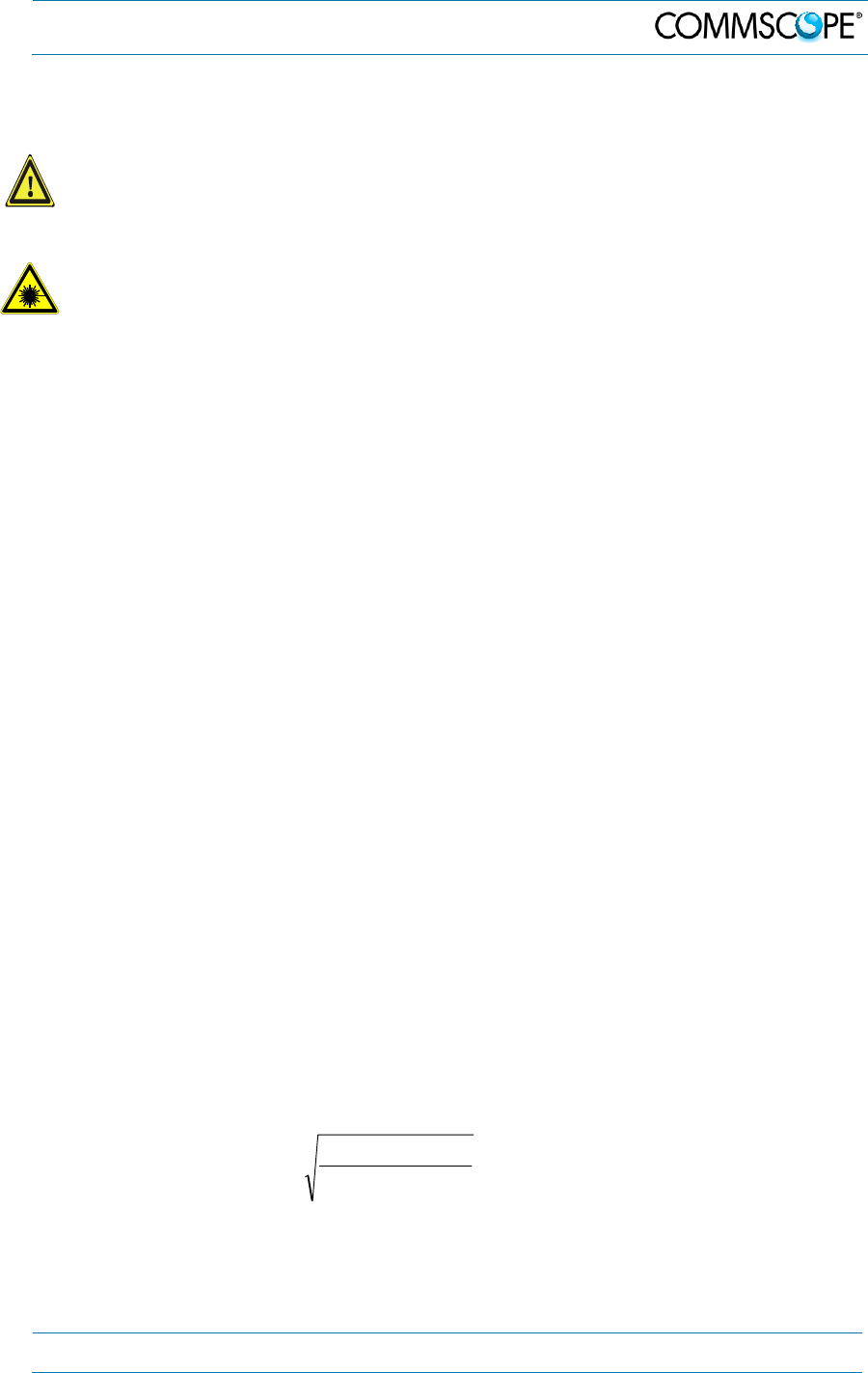
11. Warning: For installations, which have to comply with FCC RF exposure
requirements, the antenna selection and installation must be completed in a way
to ensure compliance with those FCC requirements. Depending on the RF
frequency, rated output power, antenna gain, and the loss between the repeater
and antenna, the minimum distance D to be maintained between the antenna
location and human beings is calculated according to this formula:
]/[
][
][
2
4
cmmW
mW
cm
PD
P
D
where
P (mW) is the radiated power at the antenna, i.e. the max. rated repeater
output power in addition to the antenna gain minus the loss between the
repeater and the antenna.
1. General
Page 8 7.Manual MF0200A0A ION-U_EU H 19P2_uc_08-July-13.docx
User
’
s Manual for ION
®
U
PD (mW/cm²) is the allowed Power Density limit acc. to 47 CFR 1.1310 (B)
for general population / uncontrolled exposures which is
o F (MHz) / 1500 for frequencies from 300MHz to 1500MHz
o 1 for frequencies from 1500MHz to 100.000MHz
RF exposure compliance may need to be addressed at the time of licensing, as
required by the responsible FCC Bureau(s), including antenna co-location
requirements of 1.1307(b)(3).
12. Warning: For installations which have to comply with Europe an EN50385
exposure compliance requirements, the following Power Density limits/guidelines
(mW/cm²) according to ICNIRP are valid:
o 0.2 for frequencies from 10 MHz to 400 MHz
o F (MHz) / 2000 for frequencies from 400 MHz to 2 GHz
o 1 for frequencies from 2 GHz to 300 GHz
13. Caution: Keep operating instructions within easy reach and make them available
to all users.
14. Caution: Corresponding local particularities and regulations must be observed.
For national deviations, please refer to the respective documents included in the
manual CD that is delivered with the unit.
15. Caution: Although the remote unit is internally protected against overvoltage, it is
strongly recommended to ground (earth) the antenna cables close to the
repeater’s antenna connectors for protection against atmospheric discharge.
16. Caution: ESD precautions must be observed! Before commencing maintenance
work, use the available grounding (earthing) system to connect ESD protection
measures.
17. Caution: Installation of this equipment is in full responsibility of the installer, who
has also the responsibility, that cables and couplers are calculated into the
maximum gain of the antennas, so that this value, which is filed in the FCC Grant
and can be requested from the FCC data base, is not exceeded. The industrial
boosters are shipped only as a naked booster without any installation devices or
antennas as it needs for professional installation.
18. Note: For a Class A digital device or peripheral:
This equipment has been tested and found to comply with the limits for a Class A
digital device, pursuant to part 15 of the FCC Rules. These limits are designed to
provide reasonable protection against harmful interference when the equipment is
operated in a commercial environment. This equipment generates, uses, and can
radiate radio frequency energy and, if not installed and used in accordance with
the instruction manual, may cause harmful interference to radio communications.
Operation of this equipment in a residential area is likely to cause harmful
interference in which case the user will be required to correct the interference at
his own expense.
1. General
7.Manual MF0200A0A ION-U_EU H 19P2_uc_08-July-13.docx
User
’
s Manual for ION
®
U
Page 9
19. Note: This unit complies with European standard EN60950.
Equipment Symbols Used
Please observe the meanings of the following symbols used in our equipment:
Symbol Compliance Meaning
--- FCC
WARNING. This is NOT a CONSUMER
device. It is designed for installation by FCC
LICENSEES and QUALIFIED INSTALLERS.
You MUST have an FCC LICENSE or
express consent of an FCC Licensee to
operate this device. Unauthorized use may
result in significant forfeiture penalties,
including penalties in excess of $100,000 for
each continuing violation.
---
Alert sign to R&TTE
To be sold exclusively to mobile operators or
authorized installers – no harmonised
frequency bands, operation requires license
Intended use: EU and EFTA countries
Symbol Indicates conformity with the R&TTE
directive 1999/5/EC certified by the notified
body no. 0700.

1. General
Page 10 7.Manual MF0200A0A ION-U_EU H 19P2_uc_08-July-13.docx
User
’
s Manual for ION
®
U
1.3. About CommScope
CommScope is the foremost supplier of one-stop, end-to-end radio frequency (RF)
solutions. Part of the CommScope portfolio are complete solutions for wireless
infrastructure from top-of-the-tower base station antennas to cable systems and
cabinets, RF site solutions, signal distribution, and network optimization.
CommScope has global engineering and manufacturing facilities. In addition, it
maintains field engineering offices throughout the world.
Andrew Wireless Systems GmbH based in Buchdorf/ Germany, which is part of
CommScope, is a leading manufacturer of coverage equipment for mobile radio
networks, specializing in high performance, RF and optical repeaters. Our optical
distributed networks and RF repeater systems provide coverage and capacity
solution for wireless networks in both indoor installations and outdoor environments,
e.g. tunnels, subways, in-trains, airport buildings, stadiums, skyscrapers, shopping
malls, hotels and conference rooms.
Andrew Wireless Systems GmbH operates a quality management system in
compliance with the requirements of ISO 9001 and TL 9000. All equipment is
manufactured using highly reliable material. To maintain highest quality of the
products, comprehensive quality monitoring is conducted at all fabrication stages.
Finished products leave the factory only after a thorough final acceptance test,
accompanied by a test certificate guaranteeing optimal operation.
This product meets the requirements of the R&TTE directive and the Declaration of
Conformity (DoC) itself. A current version of the CE DoC is included in this manual
CD delivered *. Any updated version of the DoC is available upon request from the
local sales offices or directly from CommScope via the local Customer Support at
one of the addresses listed in the following chapter.
According to the DoC, our "CE"-marked equipment can be used in all member
states of the European Union.
Note: Exceptions of and national deviations from this intended use may be
possible. To observe corresponding local particularities and
regulations, please refer to the respective documents (also in
national language) which are included in the manual CD delivered.
* In case the Declaration of Conformity (DoC) for the product was not included in the manual CD
delivered, it is available upon request from the local sales offices or directly from CommScope at
one of the addresses listed in the following chapter.
To make the most of this product, we recommend you carefully read the instructions
in this manual and commission the system only according to these instructions.
For technical assistance and support, please also contact the local office or
CommScope directly at one of the addresses listed in the following chapter.
1. General
7.Manual MF0200A0A ION-U_EU H 19P2_uc_08-July-13.docx
User
’
s Manual for ION
®
U
Page 11
1.4. International Contact Addresses for Customer Support
Americas:
Canada
United States
CommScope Canada Andrew LLC, A CommScope Company
Mail 505 Consumers Road, Suite 803
Toronto M2J 4V8
Canada Mail 620 North Greenfield Parkway
Garner, NC 27529
U.S.A.
Phone +1-905-878-3457 (Office)
+1-416-721-5058 (Cell) Phone +1-888-297-6433
Fax +1-905-878-3297 Fax +1-919-329-8950
E-mail Peter.Masih@commscope.com,
wisupport@commscope.com E-mail wisupport@commscope.com
Caribbean & South American Region
(CALA)
Caribbean (CALA) & Central American Region
CommScope Cabos do Brasil Ltda. CommScope Mexico S.A. de C.V.
Mail
CALA Tech Support for Distributed
Coverage & Capacity Solutions
(DCCS) products:
Rua Guaporanga, 49
Praça Seca – Rio de Janeiro – RJ
ZIP: 21320-180
Brazil
Mail
CALA Tech Support for Distributed
Coverage & Capacity Solutions
(DCCS) products:
Av. Insurgentes Sur 688, Piso 6
Col. Del Valle, CP: 03100
Mexico City
Mexico
Phone +1-815-546-7154 (Cell)
+55-15-9104-7722 (Office) Phone +52-1-55-5419-5260 (Cell)
+52-55-1346-1900 (Office)
Fax + 55-15-2102-4001 Fax +52-55-1346-1901
E-mail wisupport@commscope.com E-mail wisupport@commscope.com
APAC Countries:
China, India and Rest of Asia
Australia & New Zealand
Andrew International Corporation Andrew Corporation (Australia) Pty Ltd.
Mail
Room 915, 9/F
Chevalier Commercial Centre
8 Wang Hoi Rd
Kowloon Bay
Hong Kong
Mail
Unit 1
153 Barry Road
Campbellfield
VIC 3061
Australia
Phone +852-3106-6100 Phone +613-9300-7969
Fax +852-2751-7800 Fax +613-9357-9110
E-mail wisupport.China@commscope.com E-mail wisupport.Australia@commscope.com

1. General
Page 12 7.Manual MF0200A0A ION-U_EU H 19P2_uc_08-July-13.docx
User
’
s Manual for ION
®
U
Europe:
United Kingdom
Scandinavia
Andrew Wireless Systems UK Ltd
A
ndrew Norway (AMNW)
Mail
Unit 15, Ilex Building
Mulberry Business Park
Fishponds Road
Wokingham Berkshire
RG41 2GY
England
Mail
P.O. Box 3066
Osloveien 10
Hoenefoss 3501
Norway
Phone +44-1189-366-792 Phone + 47 32-12-3530
Fax +44-1189-366-773 Fax + 47 32-12-3531
E-mail wisupport.uk@commscope.com E-mail wisupport@commscope.com
Germany
France
Andrew Wireless Systems GmbH CommScope France
Mail Industriering 10
86675 Buchdorf
Germany Mail
Immeuble Le Lavoisier
4, Place des Vosges
92052 Courbevoie
France
Phone +49-9099-69-0 Phone +33-1 82 97 04 00
Fax +49-9099-69-930 Fax +33-1 47 89 45 25
E-mail wisupport@commscope.com E-mail wisupport@commscope.com
Austria
Switzerland
Andrew Wireless Systems (Austria) GmbH CommScope Wireless Systems AG
Mail Weglgasse 10
2320 Wien-Schwechat
Austria Mail Tiergartenweg 1
CH-4710 Balsthal
Switzerland
Phone +43-1706-39-99-10 Phone +41-62-386-1260
Fax +43-1706-39-99-9 Fax +41-62-386-1261
E-mail wisupport.austria@commscope.com E-mail wisupport.ch@commscope.com
Italy
Iberia Region - Spain & Portugal
CommScope Italy S.r.l., Faenza, Italy
A
ndrew España S.A.
A CommScope Company
Mail Via Mengolina, 20
48018 Faenza (RA)
Italy Mail
Avda. de Europa, 4 - 2ª pta.
Parque Empresarial de la Moraleja
Alcobendas, Madrid 28108
Spain
Phone +39-0546-697111 Phone +34-91-745-20 40
Fax +39-0546-682768 Fax +34-91-661-87 02
E-mail wisupport.italia@commscope.com E-mail wisupport.iberia@commscope.com
1. General
7.Manual MF0200A0A ION-U_EU H 19P2_uc_08-July-13.docx
User
’
s Manual for ION
®
U
Page 13
Czech Republic
CommScope Solutions Czech Republic
C-Com, spol. s r.o
Mail U Moruší 888
53006 Pardubice
Czech Republic
Phone +49 871 9659171 (Office)
+49 171 4001166 (Mobile)
Fax +49 871 9659172
E-mail wisupport@commscope.com
Africa & Middle East:
Middle East & North Africa
South Africa
CommScope Solutions International Inc.
(Branch) Andrew Wireless Solutions Africa (PTY)
LTD
Mail
PO Box 48 78 22
Unit 3206, Floor 32,
Jumeirah Business Center 5,
Jumeirah Lakes Towers,
Dubai
United Arab Emirates
Mail
11 Commerce Crescent West
Eastgate, Sandton
PO Box 786117
Sandton 2146
South Africa
Phone +971 4 390 09 80 Phone + 27 11-719-6000
Fax +971 4 390 86 23 Fax + 27 11-444-5393
E-mail wisupport@commscope.com E-mail wisupport@commscope.com
table 1-1 List of international contact addresses

2. Introduction
Page 14 7.Manual MF0200A0A ION-U_EU H 19P2_uc_08-July-13.docx
User
’
s Manual for ION
®
U
2. Introduction
2.1. Purpose
Mobile telephone and public safety systems transmit signals in two directions
between base transceiver station (BTS) and mobile stations (MS) within the signal
coverage area to carry voice and data traffic.
If weak signal transmissions occur within the coverage area because of indoor
applications, topological conditions or distance from the transmitter, extension of the
transmission range can be achieved by means of an optical distributed antenna
system (DAS).
Office buildings, sports arenas, college campuses, industrial parks, and other areas
of high demand require the specialized capacity boost that an optical DAS can
provide to meet increasing customer demands for voice and data.
An optical DAS contains optical Master Units and a sufficient number of Remote
Units to provide the necessary coverage. The number of the Remote Units depends
on the coverage requirements of the DAS. The Remote Units are connected to the
Master Unit with optical links.
The Master Unit is the connection to the Base Transceiver Stations. The
configuration of a Master Unit depends on the number of the Remote Units and the
frequency range.
RF signals are transported to and from the remote units via optical fibers.
2.2. ION-U High Power Remote and Extension Units
The ION-U is an optical fiber based DAS system that efficiently takes the outputs of
multiple Base Transceiver Stations (BTS) sectors and converts those RF signals to
optical to send them over fiber optic cables to remote units to provide coverage in
indoor and outdoor locations. The system supports both low power and high power
remotes units and SISO and MIMO operation.
The ION-U H 19P2 is a high-power multi-operator 1900 MHz band Extension Unit
(EU). It works in conjunction with a Master Unit in the ION-U optical distribution
system and is connected to the main Remote Unit via an extension cable bridge.
The Extension Unit adds an additional band (1900 MHz) to the main Remote Unit
using the same fiber allowing multiple operators to transport signals to the DAS. The
additional service or frequency band provided by the Extension Unit is achieved
without any impact on the installed network.
The compact mechanical design is specifically architected to be mounted inside
poles or next to the main Remote Unit with a minimal visual impact. A shroud is
available to mount the RU and EU in a single protected structure.
3. Functional Description
7.Manual MF0200A0A ION-U_EU H 19P2_uc_08-July-13.docx
User
’
s Manual for ION
®
U
Page 15
3. Functional Description
3.1.1. Fan Protection Kit
In order to protect the fan unit in outdoor use (e.g. against rain), a protective cover is
delivered with the unit that can be mounted over the fan unit. For indoor applications,
mounting of the fan-protection kit is not mandatory.
3.1.2. Accessories
A number of accessories are available for the Remote Unit such as shrouded
housing, connecting boxes, and iso-trafo kits.
A short version of the Extension Unit designed to be mounted in a protective shroud
is also available. The shroud provides protection for the Remote Unit, an Extension
Unit, and an optional cross-band coupler. The short versions of the RU and EU are
required when using the shroud.
figure 3-1 Shroud with RU and EU
4. Commissioning
Page 16 7.Manual MF0200A0A ION-U_EU H 19P2_uc_08-July-13.docx
User
’
s Manual for ION
®
U
4. Commissioning
4.1. High Power RU Mechanical Installation
4.1.1. General
Read the health and safety warnings in chapter 1.2.
1. Warning: Do not install the unit in a way or at a place where the
specifications outlined in the Environmental and Safety Specifications
leaflet of the supplier are not met.
2. WARNING: IMPROPER INSTALLATION CAN LEAD TO EQUIPMENT
FALLING CAUSING SERIOUS PERSONAL INJURY OR DAMAGE TO
EQUIPMENT. Installer must verify that the supporting surface will safely
support the combined load of the electronic equipment and all attached
hardware and components. The supporting wall should be solid wood or
concrete using appropriate screws and dowels (wall anchors).
3. Warning: It is recommended to use the mounting hardware delivered by the
manufacturer only. If different mounting hardware is used, the
specifications for stationary use of the Remote Unit must not be exceeded.
Note: Exceeding the specified load limits may cause the loss of warranty!
4. Warning: The unit is considerably heavy. Make sure that a suitable
mounting surface is used. Ensure there is adequate manpower to handle
the weight of the system.
5. Caution: Due to power dissipation, the Remote Unit may reach a very high
temperature. Ensure sufficient airflow for ventilation.
6. Note: When connecting and mounting the cables (RF, optical, mains, ...)
ensure that no water can penetrate into the unit through these cables.
7. Note: Observe all additional rules or restrictions regarding mounting that
apply to specific Remote Unit types.
8. Note: Observe all additional rules or restrictions regarding mounting that
apply to specific Remote Unit types. For details refer to the mechanical
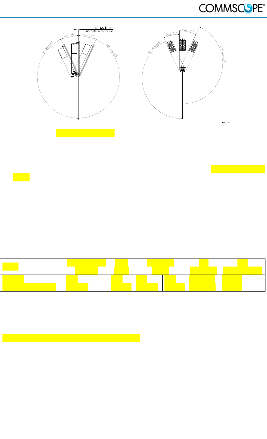
specifications in the data sheet for the unit. Install the unit vertically with
the fan unit at the top. A maximum tilt angle of 25° from a vertical position
must be maintained, as shown in the following illustrations:
4. Commissioning
7.Manual MF0200A0A ION-U_EU H 19P2_uc_08-July-13.docx
User
’
s Manual for ION
®
U
Page 17
9. A spacing of 40 mm (1.66 inch) around the unit is required.
10. To ensure sufficient airflow when mounting the unit in enclosed spaces, two
lid openings (one for the air inlet and the other for the air outlet) must be
provided. Do not block these air inlets and outlets when mounting the
remote unit. The size of each opening must equal at least 12 x 12 cm (144
cm
2
). Ensure that there is no thermal short circuit between the air inlet and
air outlet.
If any different or additional mounting material is used, ensure that the mounting
remains as safe as the mounting designed by the manufacturer. Ensure that the
static and dynamic strengths are adequate for the environmental conditions of the
site. The mounting itself must not vibrate, swing or move in any way that might cause
damage to the Remote Unit.
Specified torques must be observed for certain mounting procedures according to the
following table:
Type Tallow-drop
screws Hex
nuts Spacing
bolts PG
(plastic) PG
(aluminium)
Thread M 4 M 8 M 4 M 8 PG 13.5 PG 29
Specified torques 3.3 Nm 27 Nm 2.3 Nm 27 Nm 3.75 Nm 10 Nm
table 4-1 Specified torques
The mounting procedures for a stand-alone remote unit without optional accessories
are described and illustrated in the following sections. For further information
regarding special mounting procedures including mounting of accessory equipment,
please see the separate accessories manual.
4. Commissioning
Page 18 7.Manual MF0200A0A ION-U_EU H 19P2_uc_08-July-13.docx
User
’
s Manual for ION
®
U
4.1.2. Wall-Mounting Procedure
Check the suitability of the wall-mounting kit and the wall.
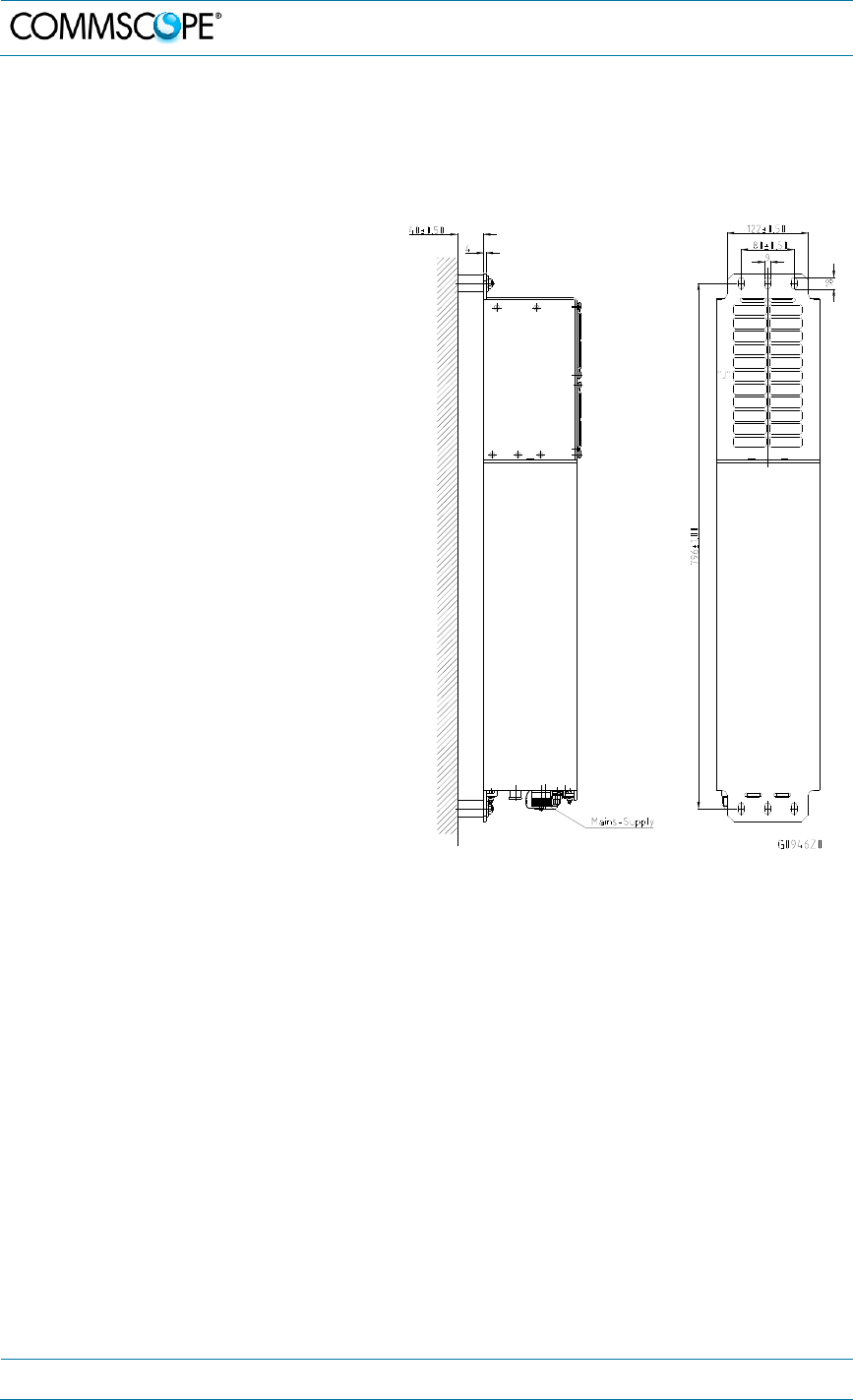
1. Mark the position of the drilling
holes (for measurements refer to
(figure 4-1 Wall Mounting). Drill
four holes at the marked positions
and insert dowels*.
Use a cap nut or lock nut to screw
the four dowel screws into the
dowels and put the distance tubes
over the screws.
Hang the mounting brackets of the
remote unit into the screws, and
fasten them immediately using the
washers and nuts.
Ensure that there is free access to
the electrical connections as well
as to the cabinet. The approved
bending radius of the connected
cables must not be exceeded.
figure 4-1 Wall Mounting
* The dowels are not included with the delivery because the suitable type depends on the on-site
conditions (material of wall). Use dowels or other fasteners that are the most appropriate for the
mounting surface.
It is the responsibility of the installer to verify that the supporting surface will
safely support the combined load of the electronic equipment and all attached
hardware and components and to ensure that the RU/EU is safely and securely
mounted.
4. Commissioning
7.Manual MF0200A0A ION-U_EU H 19P2_uc_08-July-13.docx
User
’
s Manual for ION
®
U
Page 19
4.1.3. Pole Mounting Procedure
Standard mounting hardware cannot be used to mount the remote unit to a pole, a
column, or other similar structures. Additional hardware must be used for this type of
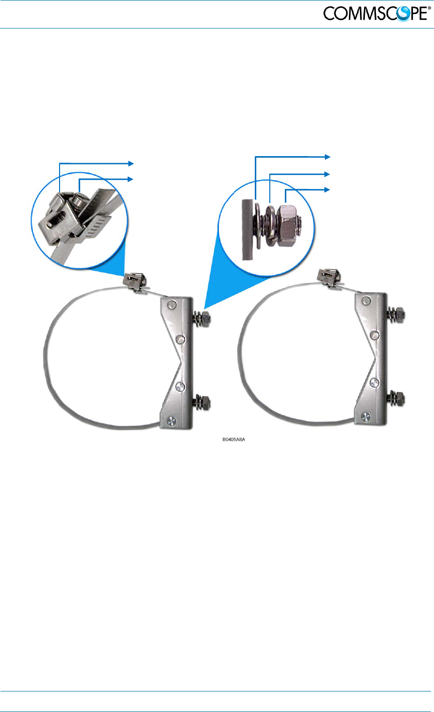
installation. The pole-mounting kit includes two mounting brackets with screw band
(worm gear) clamps to mount the brackets to the pole and two nuts, flat washers, and
lock washers per bracket to attach the remote unit to the bracket.
figure 4-2 Pole mounting kit
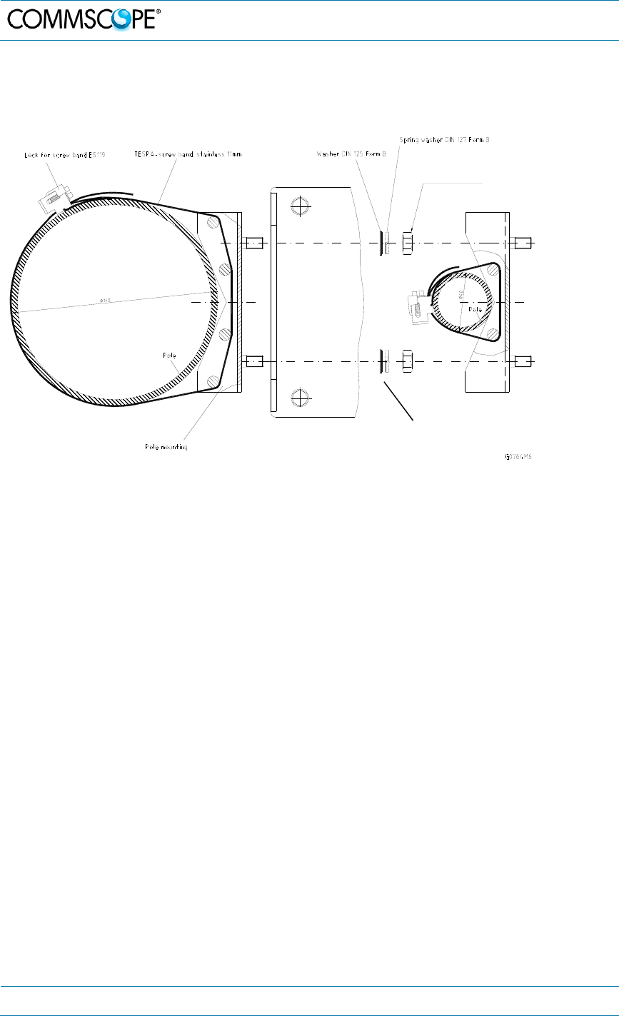
Use the screw bands to fasten the two brackets to the pole as illustrated in figure
4-3 Pole mounting drawing.
Place the bands around the pole or post and feed the loose end into the lock as
shown and tighten the slotted screw securely. When the screw is turned
clockwise, it acts as a worm drive pulling the threads of the band causing the
band to tighten around the pole.
Note: When fastening the brackets make sure that they are installed
congruently and not at an angle to each other. To determine the
distance between the clamps refer to figure 4-1 Wall Mounting for
measurements.
Flat washer
Lock washer
Nut
Mounting bracket 1 with screw clamp Mounting bracket 2 with screw clamp
Lock for screw band
Slotted screw to
tighten clamp
4. Commissioning
Page 20 7.Manual MF0200A0A ION-U_EU H 19P2_uc_08-July-13.docx
User
’
s Manual for ION
®
U
Hang the remote/extension unit mounting brackets onto the threaded bolts of the
bracket, and fasten them using the flat washers, spring (lock) washers and M8
nuts.
figure 4-3 Pole mounting drawing
Ensure that there is free access to the electrical connections as well as to the
cabinet. The approved bending radius of the connected cables must not be
exceeded.
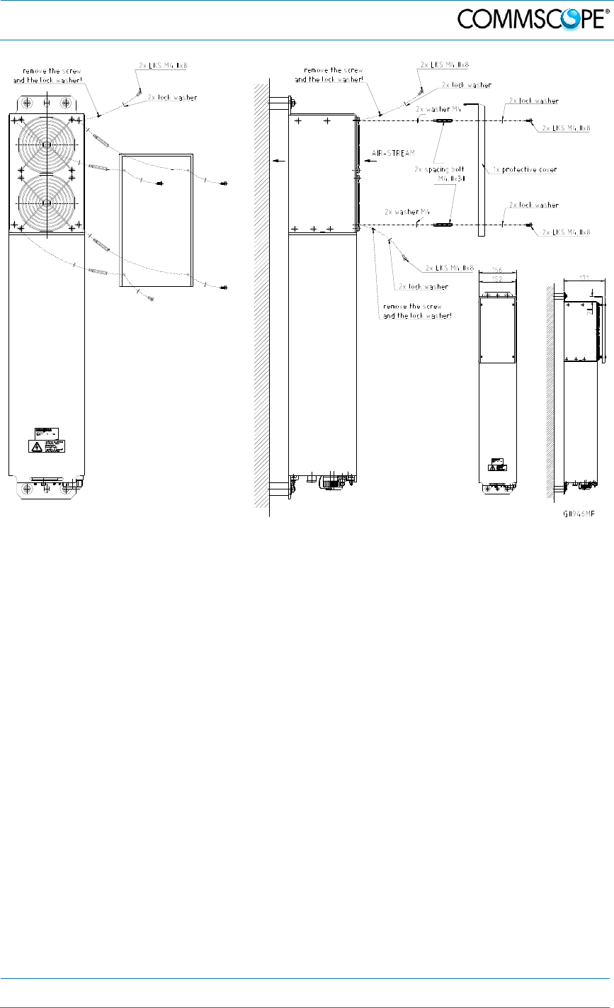
4.1.4. Mounting of Fan Protection
Fan protection is required for the outdoor usage of a stand-alone remote unit.
Mounting of the optional fan protection is described below.
To install the protective cover of the fan protection kit, first remove the four screws
with their respective lock washers from the cover of the air inlet of the remote unit,
and replace them with four spacing bolts M4.0x30 with the four lock washers
M4.0 DIN125 that are part of the fan protection kit.
Place the protective cover into position by aligning its four bore holes over the
spacing bolts and fasten it using the original lock washers and screws of the
remote unit. (These lock washers and screws are also part of the fan protection
kit and can be used as spare parts in case of loss.)
Nut M8 DIN 934
Optical remote unit
4. Commissioning
7.Manual MF0200A0A ION-U_EU H 19P2_uc_08-July-13.docx
User
’
s Manual for ION
®
U
Page 21
figure 4-4 Mounting procedure for fan protection

4. Commissioning
Page 22 7.Manual MF0200A0A ION-U_EU H 19P2_uc_08-July-13.docx
User
’
s Manual for ION
®
U
4.2. Electrical Installation
4.2.1. General
Read the health and safety warnings in chapter 1.2.
1. Warning: This unit contains dangerous voltages. Loss of life, severe personal
injury, or property damage can be the result if the instructions contained in this
manual are not followed.
2. Caution: It is compulsory to ground (earth) the unit before connecting the power
supply. A grounding bolt is provided on the cabinet to connect the ground-bonding
cable.
3. Caution: Although the remote unit is internally protected against overvoltage, it is
strongly recommended to ground (earth) the antenna cables close to the antenna
connectors of the remote unit for protection against atmospheric discharge. In
areas with strong lightning, it is strongly recommended to install additional
lightning protection.
4. Caution: If the mains connector of the remote unit is not easily accessible, a
disconnect device in the mains power circuit must be provided within easy reach.
5. Caution: Before connecting or disconnecting the mains connector at the remote
unit, ensure that mains power supply is disconnected.
6. Caution: Make sure that an appropriate circuit breaker acting as a disconnect
device (as required by IEC/EN60950-1) and an overcurrent limiting device are
connected between mains power and the Remote Unit.
7. Caution: A connection of the mains supply to a power socket requires the power
socket to be nearby the remote unit.
8. Caution: Incorrectly wired connections can destroy electrical and electronic
components.
9. Caution: To avoid corrosion at the connectors caused by electrochemical
processes, the material of the cable connectors must not cause a higher potential
difference than 0.6 V (see electrochemical contact series).
10. Note: Use an appropriate torque wrench to tighten the 7/16 DIN-type (1 ¼ -inch
opening) antenna connectors to a coupling torque of 25 N-m / 19 ft lb. Torque
wrench item no. 244377, available from the CommScope e-catalog, is
recommended. Do NOT use your hands or any other tool (e. g. a pair of pliers)!
This might cause damage to the connector and lead to a malfunction of the
Remote Unit or increased PIM.
11. Caution: For unstabilized electric networks, which frequently generate spikes, the
use of a voltage limiting device is advised.
4. Commissioning
7.Manual MF0200A0A ION-U_EU H 19P2_uc_08-July-13.docx
User
’
s Manual for ION
®
U
Page 23
12. Caution: The unit complies with the surge requirement according to EN 61000-4-
5 (fine protection); however, installation of an additional medium (via local supply
connection) and/or coarse protection (external surge protection) is recommended
depending on the individual application in order to avoid damage caused by
overcurrent.
13. Caution: Observe the labels on the front panels before connecting or
disconnecting any cables.
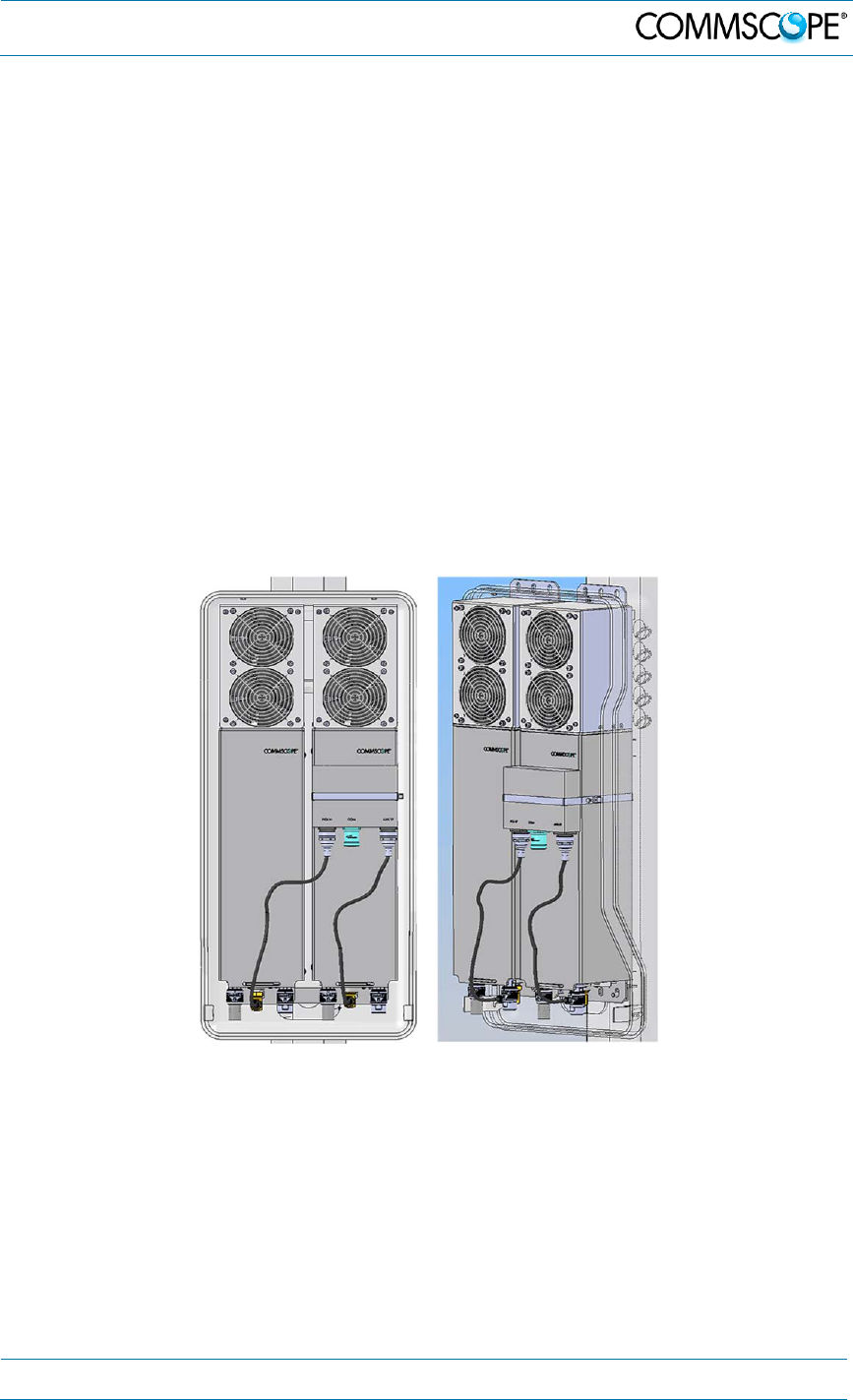
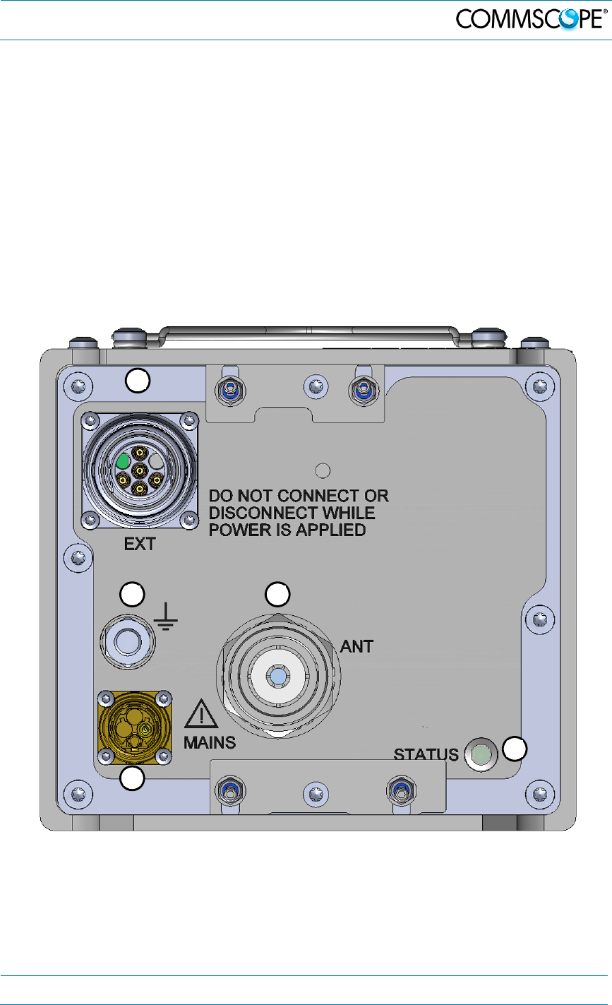
4.2.2. Connections
The ION-U EU ports and connectors shown below are located at the base of the EU.
figure 4-5 ION-U H 17P2 Connectors
A
B C
D
E
4. Commissioning
Page 24 7.Manual MF0200A0A ION-U_EU H 19P2_uc_08-July-13.docx
User
’
s Manual for ION
®
U
ION-U High Power EU Connectors/Indicators
Port/Conn Purpose Type
EU
This connector is used to interconnect to an
Remote unit using a cable bridge. Radiall Opus
M424400-
003
Grounding
Bolt
Ground (earth) bolt for connecting the mandatory
ground cable to the EU M8 bolt, hex
nut, &
washers
ANT
This connector is used for transmitting and
receiving signals to and from an antenna,
antenna splitter, or cross-band coupler.
7/16 DIN
type female
MAINS
This connector provides the power to RU models
that use standard AC (100 to 240 Vac) power. Coninvers
M17 –Series
P20, 4-Pin
STATUS
This LED provides a visual warning of an alarm
condition. The color of the LED indicates the
severity of the alarm.
LED
table 4-2: ION-U High Power EU Connectors
A
B
C
D
E
4. Commissioning
7.Manual MF0200A0A ION-U_EU H 19P2_uc_08-July-13.docx
User
’
s Manual for ION
®
U
Page 25
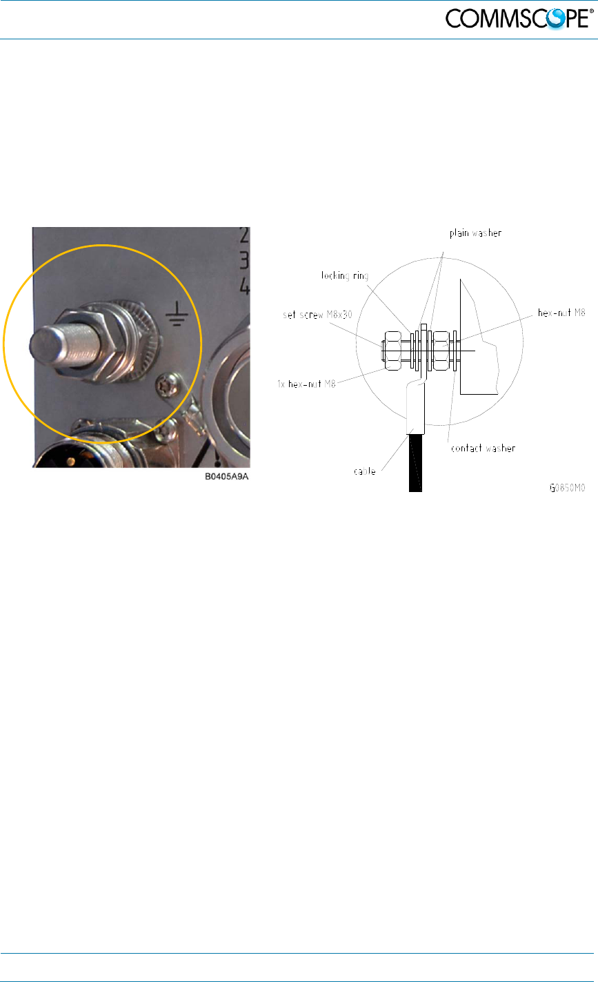
4.2.3. Grounding (Earthing)
The RU must be grounded (earthed).
1. Connect an earth-bonding cable to the grounding bolt connection provided on the
outside of the remote unit (near the Mains connector) as shown in figure 4-6. Do
not use the grounding connection to connect external devices.
figure 4-6 Grounding bolt figure 4-7 Grounding bolt, schematic view
2. After loosening the hex nut, connect the earth-bonding cable between the two
washers as illustrated in the figures above.
3. Then, fasten all parts again by tightening the hex nut.
4. Connect the other end of the ground wire to a suitable permanent ground
following local electrical code practices.
4.2.4. Connection of the Antenna Cable
The remote unit has one 7/16 DIN type antenna connector labelled “ANT”. For its
location please refer to chapter 4.2.2 Connections. When attaching the antenna
cable connector, it is recommended to refer to the corresponding documentation of
the connector manufacturer. The bending radius of the antenna cable must remain
within the given specifications.
When pairing this EU with an RU such as the ION-U H 17P2, the antenna ports of
both units can be connected to separate antennas or to an external crossband
coupler (CBC) to combine the multiple frequency bands of the two units to a single
antenna or antenna splitter.
4. Commissioning
Page 26 7.Manual MF0200A0A ION-U_EU H 19P2_uc_08-July-13.docx
User
’
s Manual for ION
®
U
The selection of cable and antenna is an important consideration. On the one hand, a
cable with higher loss is less expensive but, on the other hand, it impairs
performance.
Use an appropriate torque wrench to tighten the 7/16 DIN-type (1 ¼ -inch
opening) antenna connectors to a coupling torque of 25 N-m / 19 ft lb.
Torque wrench item no. 244377, available from the CommScope e-
catalog, is recommended. Do NOT use your hands or any other tool (e. g.
a pair of pliers)! This might cause damage to the connector and lead to a
malfunction of the Remote Unit or increased PIM.
To minimize passive inter-modulation (PIM) distortion, attention must be
paid to the physical condition of the connector junctions. Do not use
connectors that show signs of corrosion on the metal surface. Prevent
the ingress of water into the connector. Attach and torque the
connectors properly.
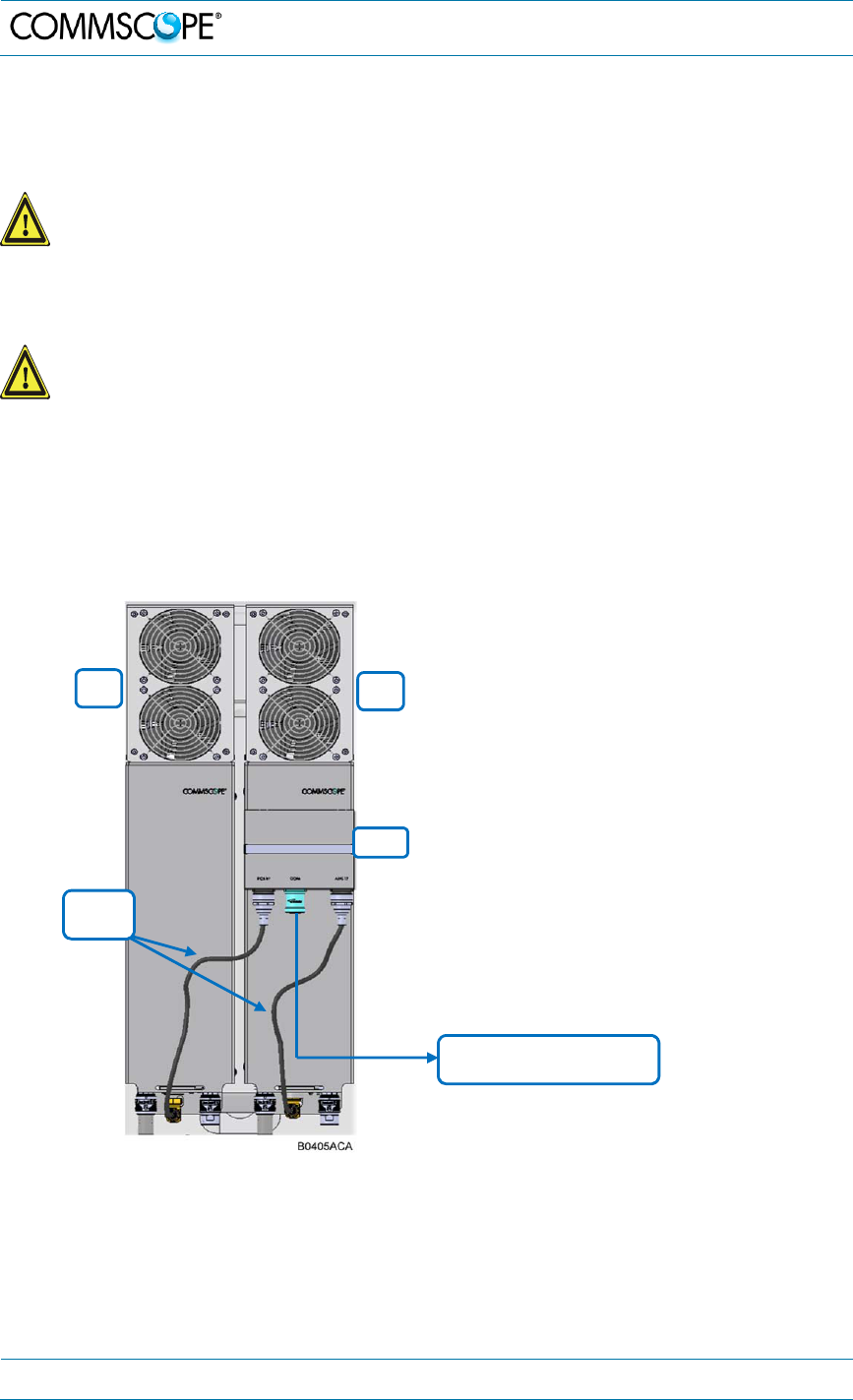
An example of the antenna port connections for a Remote Unit paired with an
Extension Unit using an optional crossband coupler is shown below.
figure 4-8 Antenna port to CBC
wiring
1. Connect an RF cable from the ANT
port of the EU to the PCS input of the
CBC.
2. Connect an RF cable from the ANT
port of the RU to the AWS input of the
CBC
3. Route the antenna cable from the
antenna or splitter to the CBC.
4. Cut the cable to length and terminate
the cable with a 7/16 DIN type male
connector.
5. Using an appropriate torque wrench,
connect the antenna cable to the
Common port of the CBC.
EU RU
CBC
RF
Cables
COM: Connect to antenna
or antenna network
4. Commissioning
7.Manual MF0200A0A ION-U_EU H 19P2_uc_08-July-13.docx
User
’
s Manual for ION
®
U
Page 27
4.2.5. Mains Power Connection
Before connecting electrical power to the units, the system must be grounded as
described in chapter 4.2.3.
Mains power must be connected at the mains connector of the unit (see chapter
4.2.2 Connections).
Use the following method to install and connect the Mains power to the RU:
1. Locate the Mains power cable that was delivered with the RU.
2. Locate or install a suitable power junction box or receptacle near the RU and
route the power cable from the power source to the RU. Do not connect the
cable to the RU’s Mains connector at this time. The power source must be
interruptible.
3. The Mains cable must be properly secured observing local regulations and
electrical codes. Be sure to allow enough slack in the cable at the RU to plug
or unplug the cable into the Mains connector of the RU.
4. Wire the power cable to the junction box or receptacle. Refer to the color code
and pin numbers shown in figure
4-10
(AC cable), and table 4-3.
5. With the cable’s Mains plug disconnected from the RU, turn the circuit breaker
on, unscrew the plug’s protective cover, and carefully test the plug with a
voltmeter to ensure that the voltage and polarity are correct.
6. Once the testing has been completed, turn off the circuit breaker.
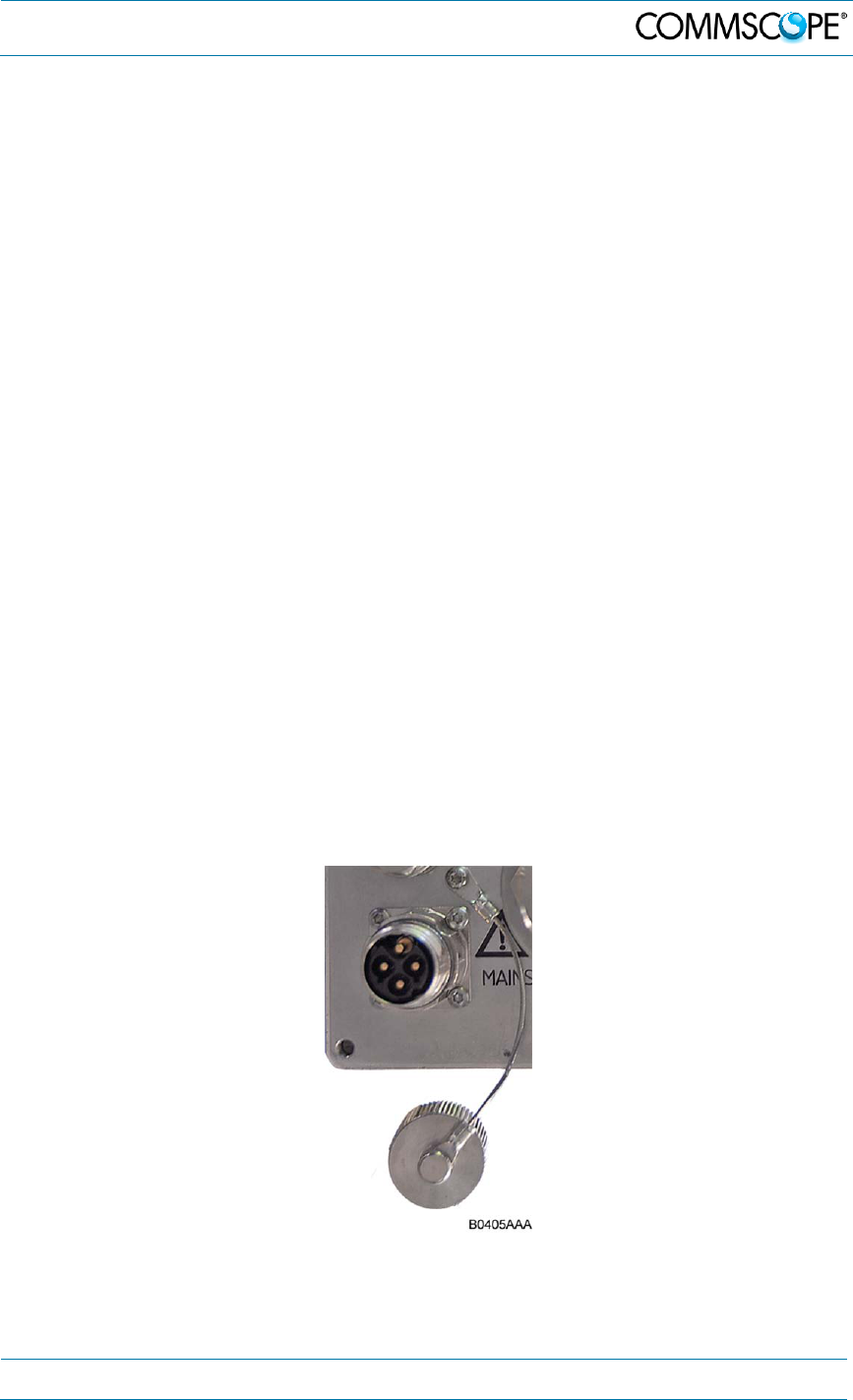
7. Unscrew the protective cover from the Mains connector of the RU (figure 4-9).
8. Insert the plug into the Mains connector and tighten the clamping ring until it is
hand tight. Do not over-tighten the clamping ring.
figure 4-9 Mains power connector
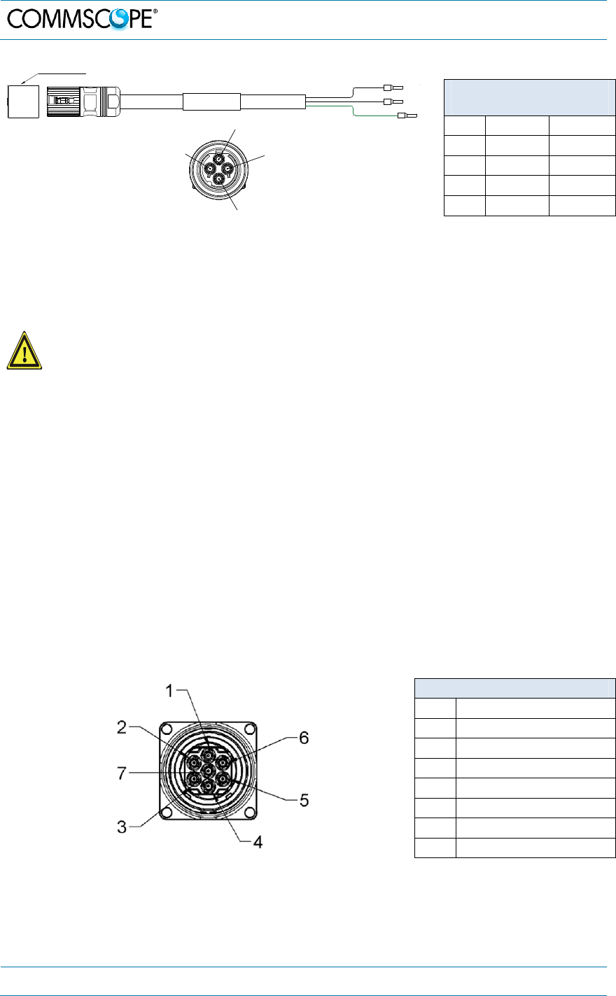
The Mains cable is part of the delivery. The wiring of the mains cable is as follows:
4. Commissioning
Page 28 7.Manual MF0200A0A ION-U_EU H 19P2_uc_08-July-13.docx
User
’
s Manual for ION
®
U
Coninvers M17 –
Series P20, 4-Pin
Pin Name Color
1 Phase Black
2 Neutral White
3 n.c. n.c
PE Ground Green
figure 4-10 Mains power cable - AC table 4-3 AC power cable
For the AC power supply connection, a minimum cross section of 1.5
mm
2
is required. Each wire must observe the applicable national
regulations regarding loop impedance, voltage drop, and methods of
installation. Make sure to connect the correct voltage to the unit.
Note: Do not connect or disconnect the power cord at the mains connector
while power is on. Turn off mains power* before connecting the
power cord at the remote unit, then, engage mains again.
* Mains power must be interrupted with an external mains breaker. For the mains breaker, observe
the following recommendation:
120 Volt / 20 Amp max. or 240 Volt / 16 Amp, single-phase, 50 / 60 Hz AC service is
needed, i.e. the external AC breaker should be 20 Amps max. for 120-Volt service or
16 Amps for 240-Volt service.
4.2.6. Extension Unit Port Connection
The EU connector is used to connect a cable bridge from the Extension Unit to the
RU. This port provides control and RF signaling to and from the Remote unit.
7-Pin
Pin Assignment
1 RF
2 n.c.
3 System Bus
4 RF (if Pin installed)
5 System Bus
6 n.c.
7 RF
figure 4-11 EU (Extension Unit) connector table 4-4
EU Connector
white
black
green
Protective Cap
PE
1
2
3
Mains Cable Connector
Front View
B0405ADA
4. Commissioning
7.Manual MF0200A0A ION-U_EU H 19P2_uc_08-July-13.docx
User
’
s Manual for ION
®
U
Page 29
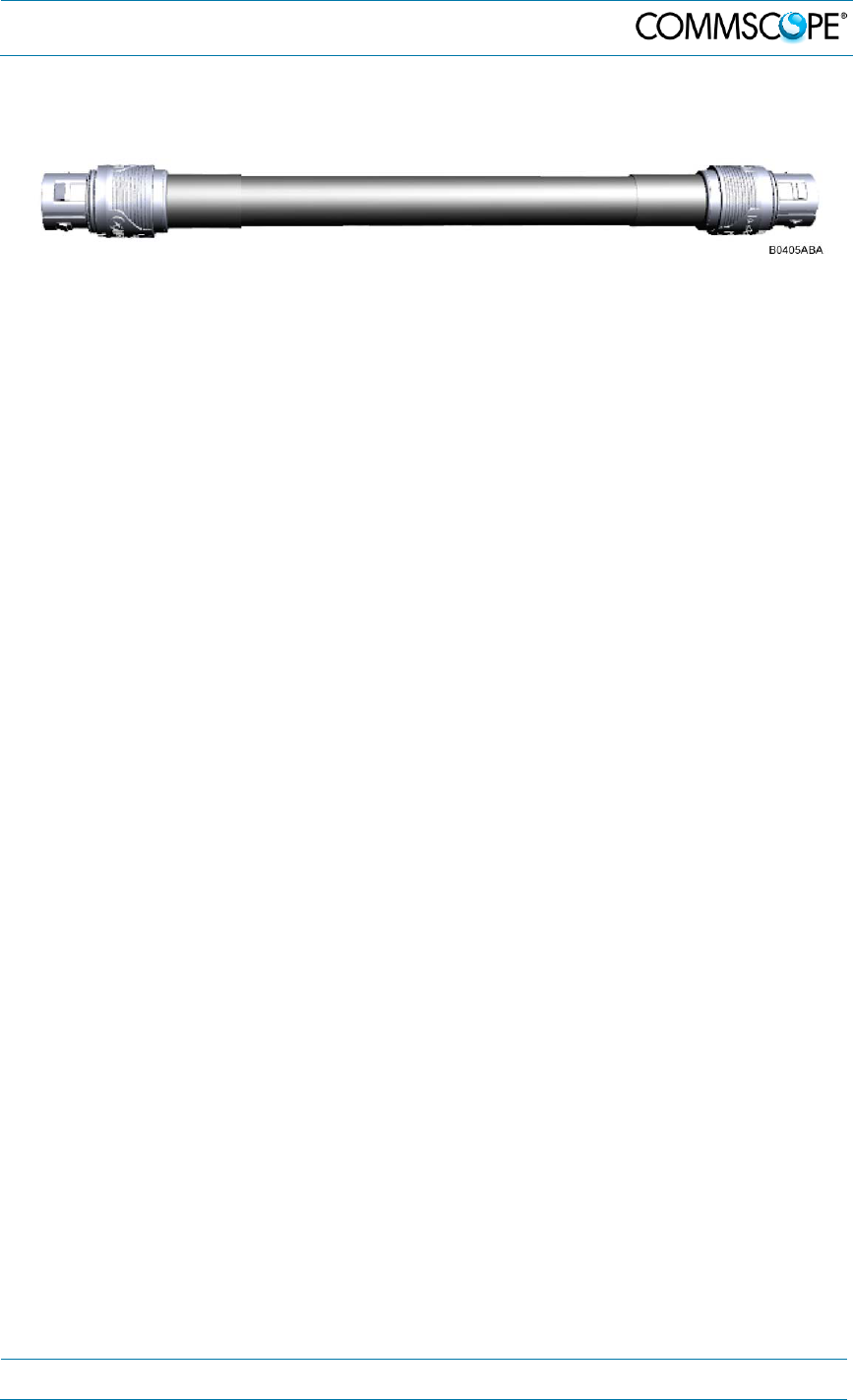
Connect the cable bridge (corrugated flexible cable) between the EU port connector
of the RU and the EU port of the Extension unit.
figure 4-12 Extension unit cable bridge

4. Commissioning
Page 30 7.Manual MF0200A0A ION-U_EU H 19P2_uc_08-July-13.docx
User
’
s Manual for ION
®
U
4.3. Commissioning
Read the health and safety warnings in chapter 1.2 Health and Safety Warnings as
well as the description carefully to avoid mistakes and proceed step by step as
described!
Do not operate the remote unit without terminating the antenna connectors.
The antenna connectors may be terminated by connecting them to their
respective antennas or to a dummy load.
Only qualified personnel should carry out the electrical, mechanical,
commissioning, and maintenance activities that require the unit to be powered
on when open.
When opening the remote unit do not damage the warranty labels on the
internal devices. The warranty is void if the seals are broken.
Ensure that all connections have been performed according to chapter 4.2.2
Connections.
4. Commissioning
7.Manual MF0200A0A ION-U_EU H 19P2_uc_08-July-13.docx
User
’
s Manual for ION
®
U
Page 31
PE
1
2
3
Coninvers M17 –
Series P20, 4-Pin
Pin Name Color
1PhaseBlack
2NeutralWhite
3 n.c. n.c
PE Ground Green
4. Commissioning
Page 32 7.Manual MF0200A0A ION-U_EU H 19P2_uc_08-July-13.docx
User
’
s Manual for ION
®
U

5. Alarms
7.Manual MF0200A0A ION-U_EU H 19P2_uc_08-July-13.docx
User
’
s Manual for ION
®
U
Page 33
5. Alarms
5.1. Bite and Alarms
The Built-In Test concept comprises the monitoring of the power supplies, the power
amplifiers and the optical interface.
All occurring alarms can be checked via software at the master unit.
5.2. Handling of Alarms
As soon as the software acknowledges a valid alarm, a message is transmitted to the
master unit.
If the reason for the alarm has been cleared or if the alarm should continue, a new
alarm message will not be repeated. If there was an interruption of at least five
seconds after acknowledgement, a new alarm message will be generated.
5.3. Alarm Status
For details refer to the corresponding software documentation of the master unit.
5.4. Status LED Alarms
For local supervision, a status LED on the connector flange of the remote unit
provides a visual indication of possible reasons for alarms. This table shows possible
on-site measures that could be checked before referring to the master unit alarm list.
For local supervision, a status LED on the connector panel of the remote unit
provides a visual warning of an alarm condition. The color of the LED indicates the
severity of the alarm. Detailed alarm information is available through the ION-U
software interface. This table lists the alarm conditions and possible on-site
measures that could be performed to resolve the issues responsible for triggering the
alarms.
5. Alarms
Page 34 7.Manual MF0200A0A ION-U_EU H 19P2_uc_08-July-13.docx
User
’
s Manual for ION
®
U
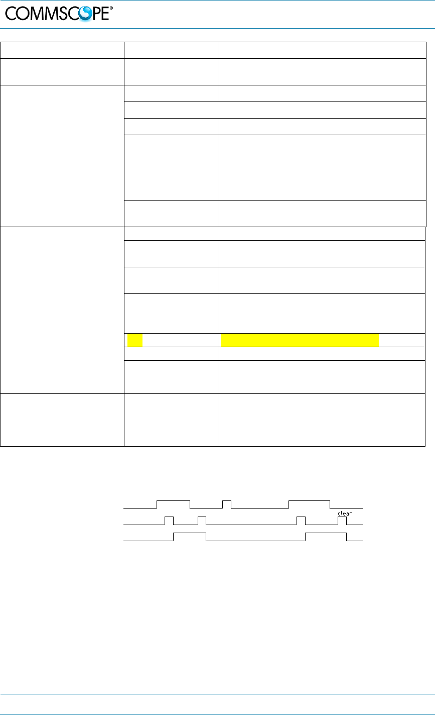
Status LED Indication Alarms Possible on-site measures
Green No alarm
Status ok
Orange
Door alarm Close the door (RUs with door).
Alarms not directly related to RU:
External alarms Check externally connected devices.
Optical alarm Rx
Check fiber loss of optical link.
Check optical connectors.
Clean optical connectors.
(MU: Check optical output power of
corresponding OTRx at master unit).
ALC alarm (MU: Decrease DL input power of
affected band).
Red
Alarms directly related to RU:
Power 28 V Change power supply (RUs with door).
Replace the affected remote unit.
Temperature Reduce environmental temperature.
Eliminate thermal short circuit.
Fan Disconnect and connect mains. Fans
should run briefly (SW version > 2.4). If
not, replace the fans at RU.
I²C Disconnect and connect mains.
Optical alarm Tx -
A
mplifier “Power
Down” (MU: Change amplifier setting at MU
controller).
Status LED off Mains
Check power switch inside of RU (RUs
with door).
Check mains cabling.
Check mains power.
table 5-1 Status LED alarms
figure 5-1 Alarm triggering
For the position of the status LED see chapter 4.2.2 Connections.
Explicit troubleshooting is available in the MU software, (software manual or WEB
Interface).
V1651A2
clear
Alarm LED
Alarm transmit
Alarm cause
raise
> 5 s < 5 s
raise
> 5 s

5. Alarms
7.Manual MF0200A0A ION-U_EU H 19P2_uc_08-July-13.docx
User
’
s Manual for ION
®
U
Page 35
5.5. Troubleshooting
The status of the remote unit can be checked via the master unit (for details please
refer to the software manual of the Master Controller). Locally, the status can be
checked at the LED, see chapter 5.4 Status LED Alarms.

6. Maintenance
Page 36 7.Manual MF0200A0A ION-U_EU H 19P2_uc_08-July-13.docx
User
’
s Manual for ION
®
U
6. Maintenance
6.1. General
Read the health and safety warnings in chapter 1.2.
Note: The remote unit does not require preventative maintenance
measures.
Note: To prevent malfunctions of the cooling system due to dirt or
pollution, it is recommended to clean the heat sink at regular
intervals. These cleaning intervals depend mainly on the location
of the remote unit and the corresponding degree of pollution.
Maintenance of the ION-U High Power RUs should be performed by replacing only
components that are described in this chapter. In order to maintain the warranty,
avoid unintentional damage to the seals on the modules.
The spare parts list, (see chapter 7.3) includes only units that can be replaced in the
field without tuning or soldering work.
Note: When sending back the unit, use appropriate packaging. Use of
the original packaging for shipping the unit is strongly
recommended!
Note: Defective parts should only be replaced by original parts from the
supplier. All service work performed inside the housing is
performed at the users own risk.
Note: Ensure the Remote Unit has been disconnected from mains power
during maintenance.
Note: Label any unlabelled cables before disconnecting them to ensure
correct reconnection.
For most maintenance procedures, appropriate tools are required to ensure correct
handling. All of these tools can be ordered from the supplier.
Note: All Remote Unit screws have a right-hand thread, and are
tightened by turning the screws clockwise and loosened by
turning them counter-clockwise with an appropriate tool.
Due to the design of the remote unit, the fan unit is the only component that should
be replaced in the field. Please contact the supplier for replacement of any other
components.
6. Maintenance
7.Manual MF0200A0A ION-U_EU H 19P2_uc_08-July-13.docx
User
’
s Manual for ION
®
U
Page 37
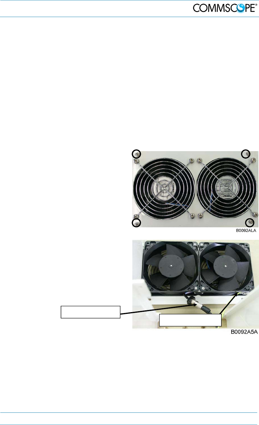
6.2. Replacing the Fan Unit
Replacement of the fan unit is not required as a preventative measure. Only when an
alarm indicates a malfunctioning of a fan, must the unit be exchanged.
Note: Please observe that the fan unit can only be replaced as a whole.
Do not remove the fans separately.
Read the health and safety warnings in chapter 1.2 Health and Safety Warnings as
well as the instructions in chapter 6.1 General before starting with the replacement.
1. Switch off the remote unit. Make sure that mains power is disconnected for
the following replacement procedure. Then, proceed as follows:
2. Loosen the four tallow-drop screws
M4x8 by which the fan plate is
attached to the cabinet. Remove the
four screws and the corresponding
washers.
3. Remove the fan unit – by putting slight
pressure on the fan plate cover –
moving it to a position that allows
access to the fan connector and the
earth-bonding cable.
4. Unscrew the fan connector and then
disconnect the earth-bonding cable.
Note: To observe the specified torque of 650 Ncm for an M5 thread, use
an appropriate tool for the following procedures.
Fan-unit connector
Earth-bonding cable
6. Maintenance
Page 38 7.Manual MF0200A0A ION-U_EU H 19P2_uc_08-July-13.docx
User
’
s Manual for ION
®
U
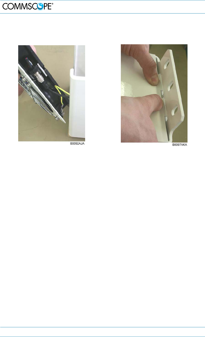
5. To mount the new fan unit, reconnect the earth-bonding cable and the fan
connector (see step 4). Then, place the fan unit back into its original position and
press it back into position as shown below:
6. Fasten the complete fan unit to the cabinet with the four tallow-drop screws M4x8
(see step 2). To prevent exceeding the specified torque of 330 Ncm, use an
appropriate tool.

6. Maintenance
7.Manual MF0200A0A ION-U_EU H 19P2_uc_08-July-13.docx
User
’
s Manual for ION
®
U
Page 39
6.3. Cleaning the Heat Sink
Note: Read the health and safety warnings in chapter 1.2 Health and
Safety Warnings as well as the instructions in chapter 6.1 General
before starting with the replacement procedure. Then, proceed as
follows:
1. Switch off the remote unit. Make sure that mains power is disconnected for the
following procedure.
2. Remove the fan plate with the fan unit from the remote unit as described in
chapter 6.2 Replacing the Fan Unit, steps 2 and 3.
3. Use compressed air (max. 5 bar) to dust, dirt, or other debris the heat sink from
back to front.
4. If the dirt cannot be blown out completely and parts of it stick to the ribs of the
heat sink, clean the parts concerned carefully from the front using e.g. a brush.
Take care that the heat sink material is not scratched or damaged.
5. After cleaning the heat sink, remount the fan unit according to chapter 6.2
Replacing the Fan Unit, steps 5 and 6. Then, switch the remote unit back on.
7. Appendix
Page 40 7.Manual MF0200A0A ION-U_EU H 19P2_uc_08-July-13.docx
User
’
s Manual for ION
®
U
7. Appendix
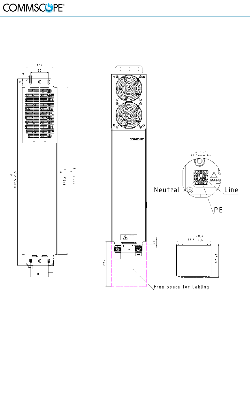
7.1. Illustrations
figure 7-1 Installation drawing-front and rear views
7. Appendix
7.Manual MF0200A0A ION-U_EU H 19P2_uc_08-July-13.docx
User
’
s Manual for ION
®
U
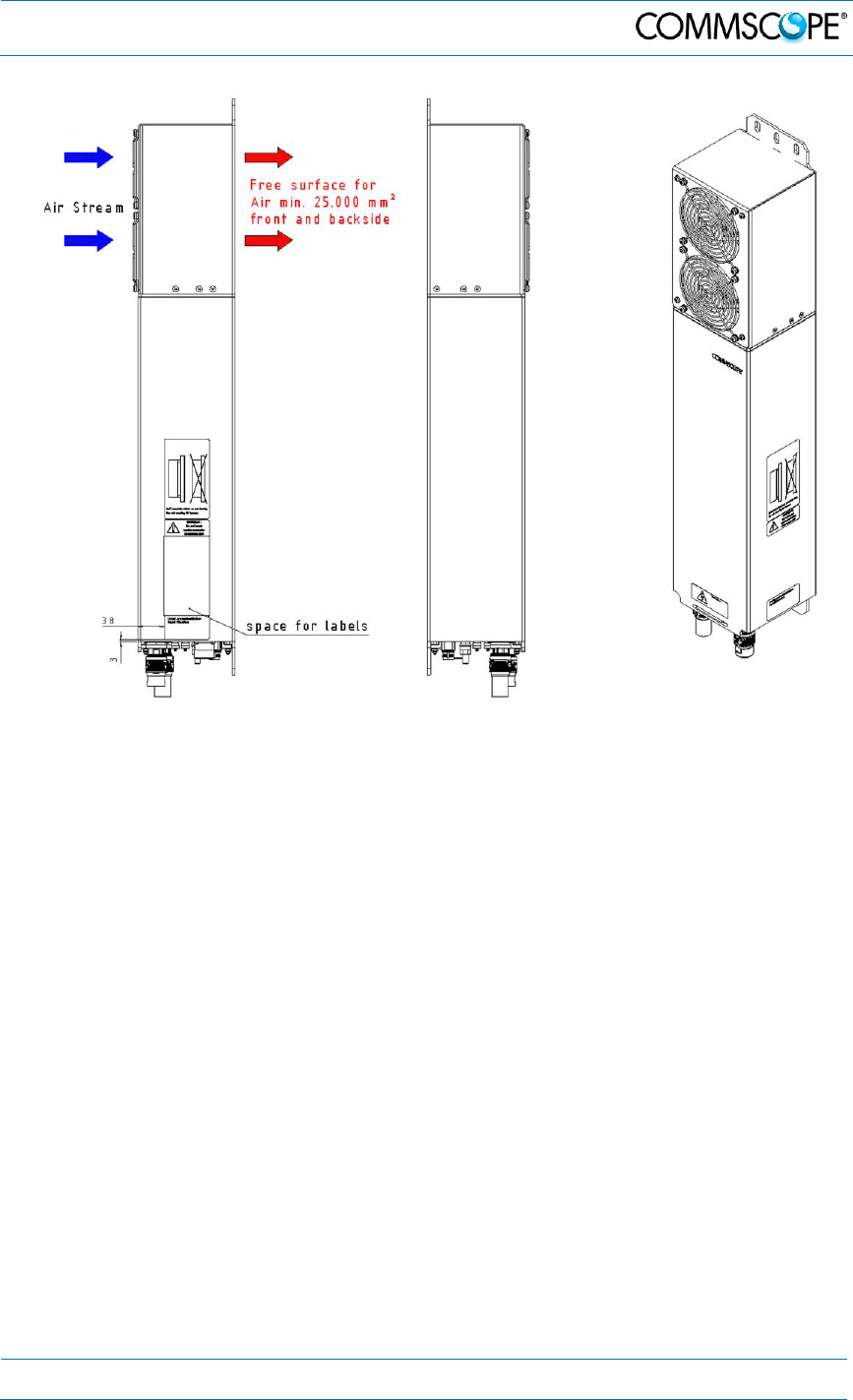
Page 41
figure 7-2 Installation drawing-side views
7. Appendix
Page 42 7.Manual MF0200A0A ION-U_EU H 19P2_uc_08-July-13.docx
User
’
s Manual for ION
®
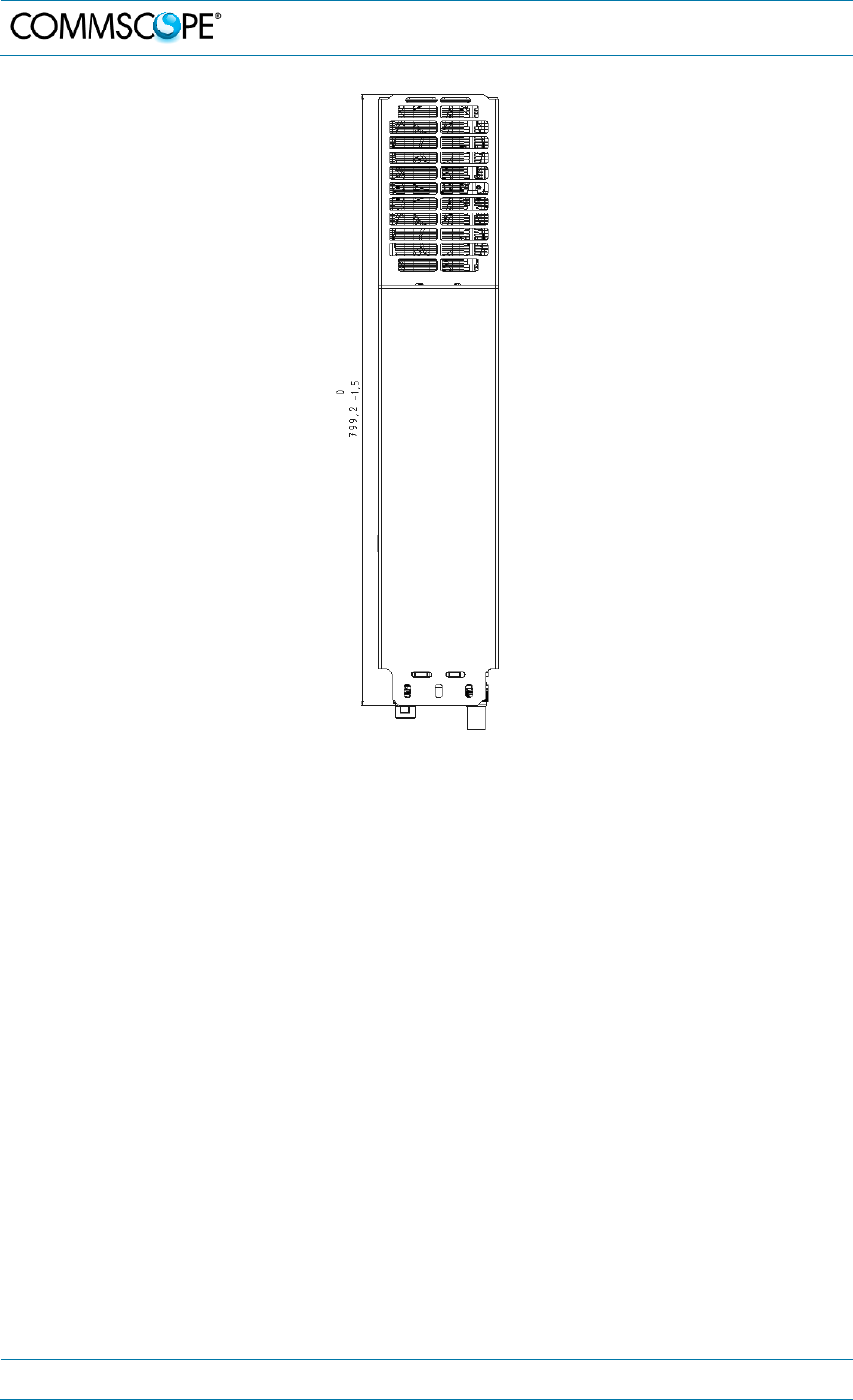
U
figure 7-3 Installation drawing-short version

7. Appendix
7.Manual MF0200A0A ION-U_EU H 19P2_uc_08-July-13.docx
User
’
s Manual for ION
®
U
Page 43
7.2. Specifications
Please refer to the ION-U_EU_H_19P2_PA-106765.x-EN.GB data sheet for the ION-
U HP EU specifications.
7.3. Spare Parts
Please contact your CommScope sales representative or DCCS Technical Support
for a current ION-U HP EU parts list.

8. Index
Page 44 7.Manual MF0200A0A ION-U_EU H 19P2_uc_08-July-13.docx
User
’
s Manual for ION
®
U
8. Index
A
Alarms
Alarm Status ...................................................... 35
Bite and Alarms ................................................. 35
Handling of Alarms ............................................ 35
Status LED ........................................................ 35
ANT RF .................................................................. 26
B
Block Diagram
ION-U EU H 19P2 ............................................. 15
C
Cable bridge ........................................................... 31
CE Declaration of Conformity (DoC) ...................... 10
Cleaning the Heat Sink .......................................... 41
Commissioning
General .............................................................. 32
CommScope ........................................................... 10
Connecting electrical power ................................... 29
Connections
Antenna ....................................................... 27, 28
Connector Panel ................................................ 25
Contact Addresses
Customer Support ....................................... 11, 12
Customer Support Addresses .......................... 11, 12
D
Declaration of Conformity (DoC) ............................ 10
E
EU connector.......................................................... 30
Expansion Unit Port ............................................... 26
G
Grounding (Earthing).............................................. 27
Grounding Bolt ....................................................... 26
H
Health and Safety Warnings .................................... 7
I
Illustrations ............................................................. 42
Installation
Electrical ........................................................... 24
Mechanical ........................................................ 18
M
MAINS .................................................................... 26
Mains cable ............................................................ 29
Maintenance .......................................................... 38
Mounting
Pole ................................................................... 21
Wall ................................................................... 20
P
Pole Mounting Procedure ...................................... 21
R
Replacement of Fan Unit ....................................... 39
S
Shroud ................................................................... 17
Spare Parts ............................................................ 45
Status ..................................................................... 26
T
Troubleshooting ..................................................... 37