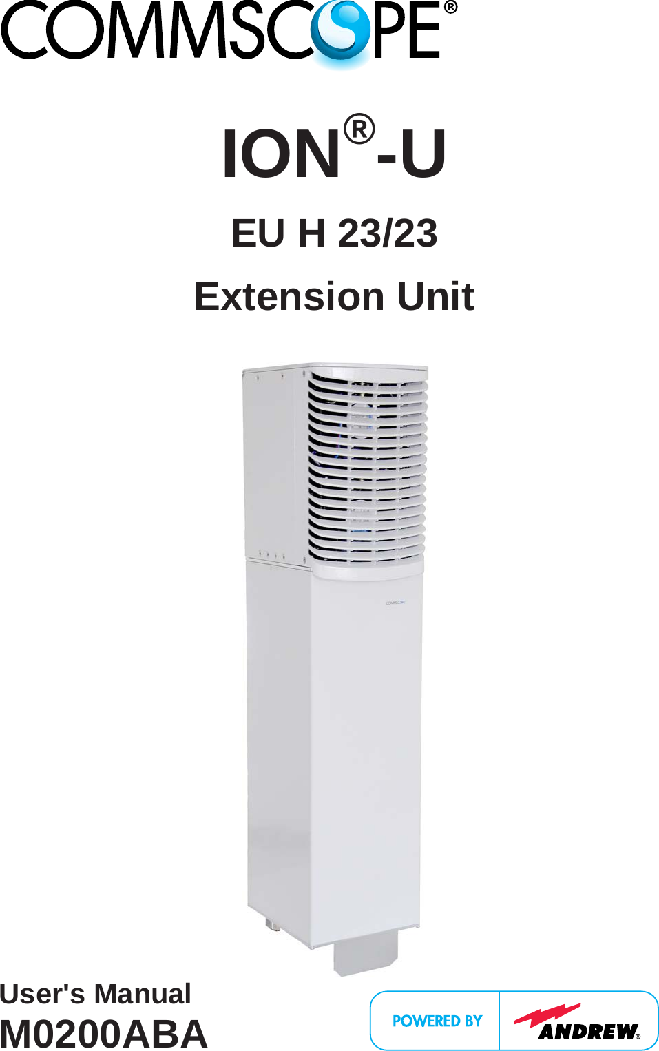
Andrew Wireless System UEUH2323 ION-U Extension Unit for cellular systems User Manual User s Manual for ION U
Andrew Wireless System ION-U Extension Unit for cellular systems User s Manual for ION U
Contents
- 1. user manual
- 2. Installation Instruction
user manual
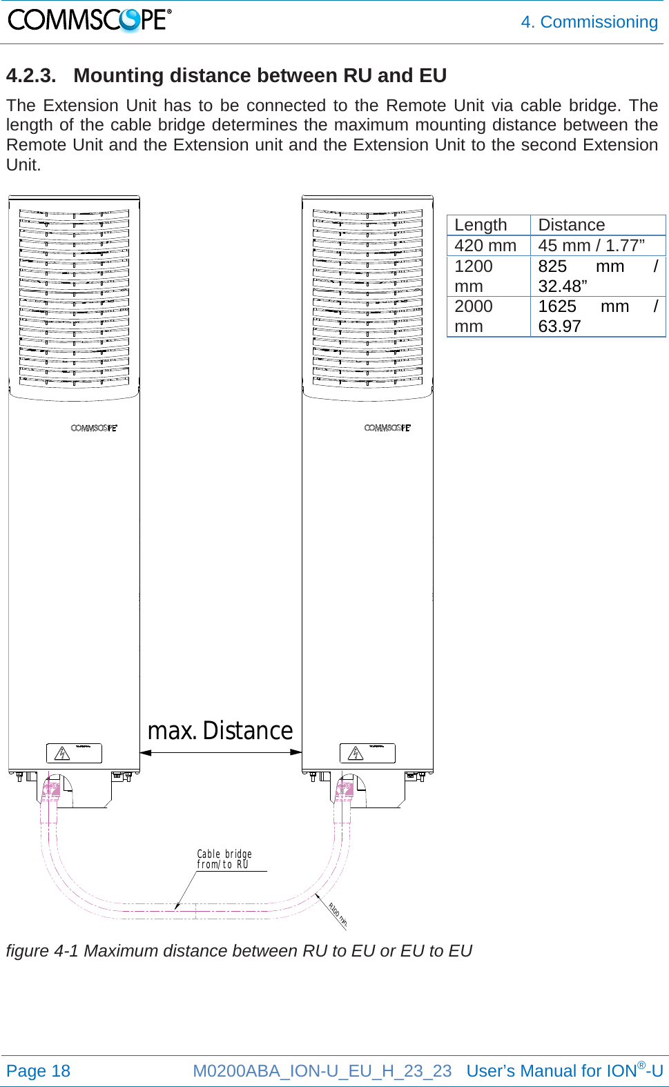
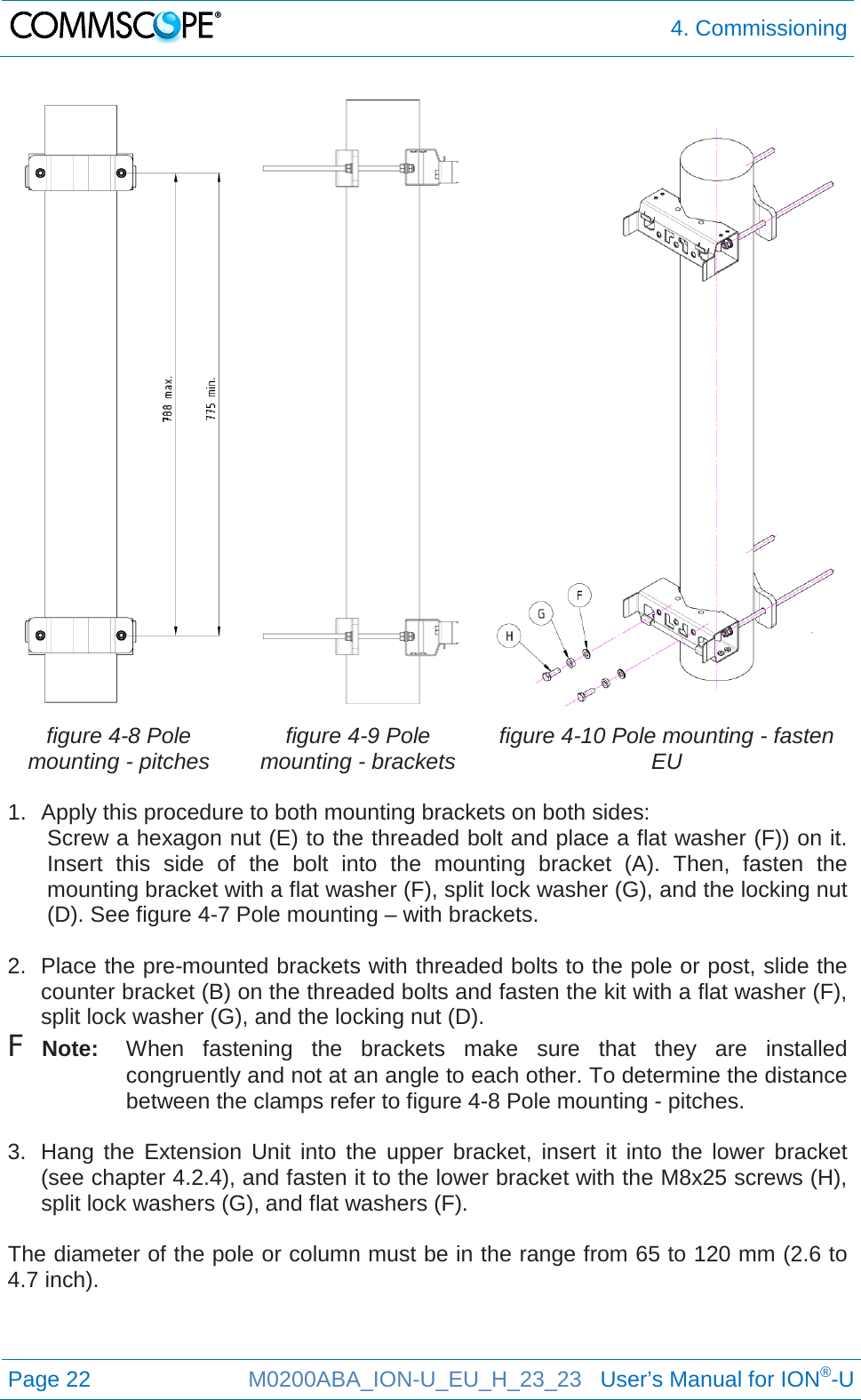
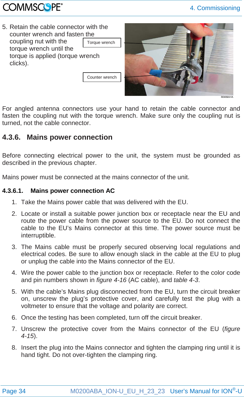
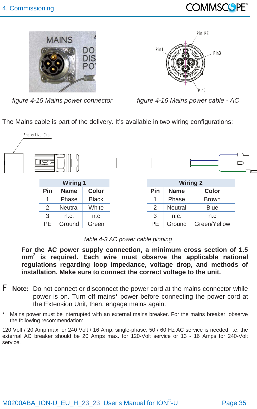
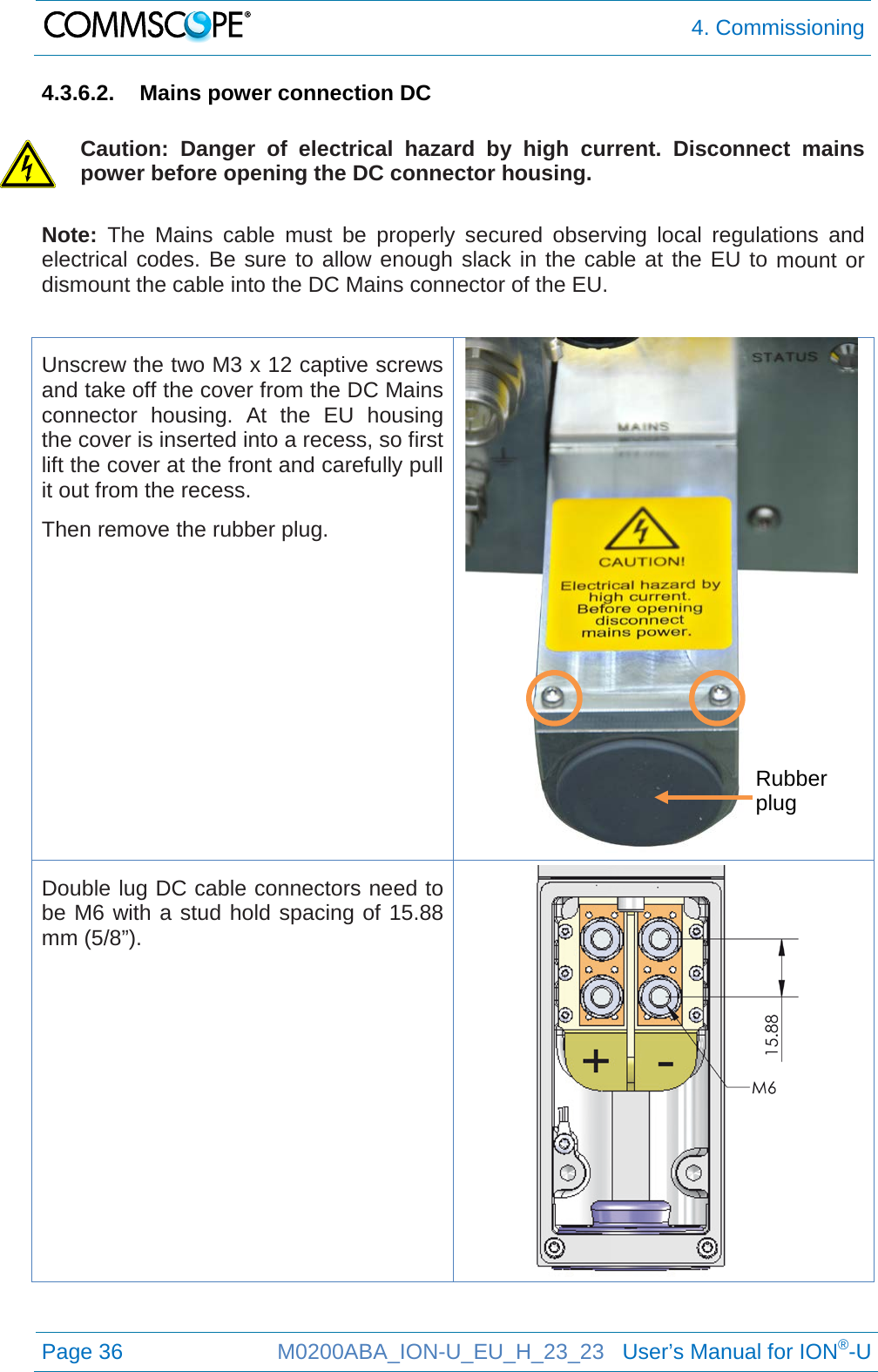
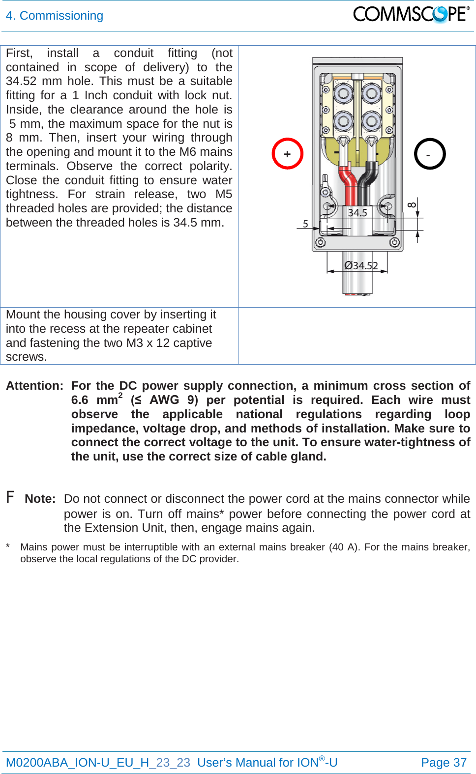
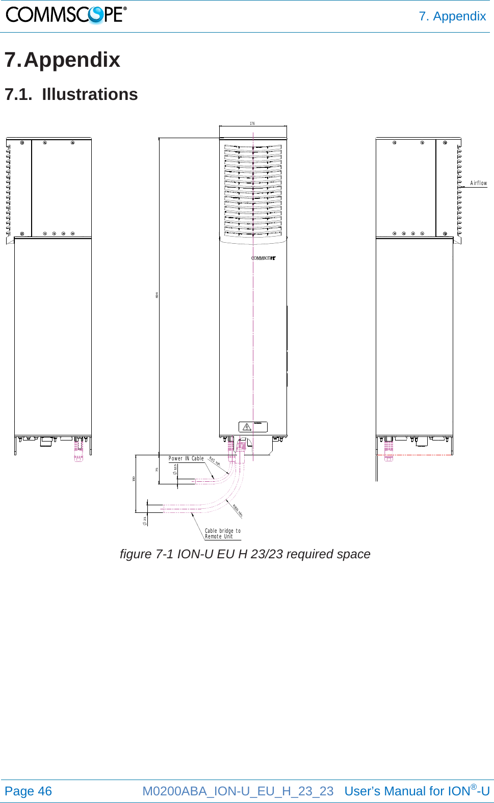
![1. General Page 8 M0200ABA_ION-U_EU_H_23_23 User’s Manual for ION®-U 8. Notice: Only license holders for the respective frequency range are allowed to operate this unit. 9. Notice: Make sure the repeater settings are correct for the intended use (refer to the manufacturer product information) and regulatory requirements are met. Do not carry out any modifications or fit any spare parts, which are not sold or recommended by the manufacturer. 1.4. Compliance 1. Notice: For installations which have to comply with European EN50385 exposure compliance requirements, the following Power Density limits/guidelines (mW/cm²) according to ICNIRP are valid: o 0.2 for frequencies from 10 MHz to 400 MHz o F (MHz) / 2000 for frequencies from 400 MHz to 2 GHz o 1 for frequencies from 2 GHz to 300 GHz 2. Notice: For installations, which have to comply with FCC RF exposure requirements, the antenna selection and installation must be completed in a way to ensure compliance with those FCC requirements. Depending on the RF frequency, rated output power, antenna gain, and the loss between the repeater and antenna, the minimum distance D to be maintained between the antenna location and human beings is calculated according to this formula: ]/[][][24cmmWmWcmPDPD∗∗=π where • P (mW) is the radiated power at the antenna, i.e. the max. rated repeater output power in addition to the antenna gain minus the loss between the repeater and the antenna. • PD (mW/cm²) is the allowed Power Density limit acc. to 47 CFR 1.1310 (B) for general population / uncontrolled exposures which is o F (MHz) / 1500 for frequencies from 300MHz to 1500MHz o 1 for frequencies from 1500MHz to 100,000MHz RF exposure compliance may need to be addressed at the time of licensing, as required by the responsible FCC Bureau(s), including antenna co-location requirements of 1.1307(b)(3). 3. Notice: Installation of this equipment is in full responsibility of the installer, who has also the responsibility, that cables and couplers are calculated into the maximum gain of the antennas, so that this value, which is filed in the FCC Grant and can be requested from the FCC data base, is not exceeded. The industrial boosters are shipped only as a naked booster without any installation devices or antennas as it needs for professional installation.](https://usermanual.wiki/Andrew-Wireless-System/UEUH2323.user-manual/User-Guide-2749658-Page-8.png)