Andrew 400BDA Downlink Booster User Manual Manual
Andrew Corporation Downlink Booster Manual
Andrew >
Manual

Wireless Innovations Group
2601 Telecom Parkway
Richardson, Texas 75082
400/800 MHz Fiber Optic & RF Fed Bi-Directional
Amplifier Operations / Maintenance Manual
DWG NO:
Error! Not a valid link.
Rev:
Error!
Not a
valid
link.
Date:06/16/2004 Page:
1 of 63
OPERATIONS / MAINTENANCE MANUAL
For
400MHz Fiber Optic Fed & RF Fed
Bi-Directional Amplifier
AE04A-D1248-001
AE04A-D1246-001
800MHz Fiber Optic Fed & RF Fed
Bi-Directional Amplifier
AE04A-D1437-001
AE04A-D1436-001
MANUAL NO. AE04B-A1669
REVISION A
The information set forth in this document and all rights in and to
inventions disclosed herein, and patents that might be granted
thereon disclosing, employing or covering the materials, methods,
techniques or apparatus described herein are the exclusive
property of Andrew Corporation.
This document is an operation and maintenance manual. No
disclosure or reproduction of the information or drawings shall be
made of any other purpose without the prior written consent of
Andrew Corporation. Use of the information contained herein to
fabricate or assemble any item in whole or in part is expressly
prohibited.

Wireless Innovations Group
2601 Telecom Parkway
Richardson, Texas 75082
400/800 MHz Fiber Optic & RF Fed Bi-Directional
Amplifier Operations / Maintenance Manual
DWG NO:
Error! Not a valid link.
Rev:
Error!
Not a
valid
link.
Date:06/16/2004 Page:
2 of 63
Table of Contents
INTRODUCTION ..................................................................................................................................... 5
Scope.........................................................................................................................................................................5
Purpose.....................................................................................................................................................................5
G
LOSSARY OF
T
ERMS
................................................................................................................................6
1.0
SAFETY CONSIDERATIONS ..................................................................................................... 7
1.1 Electric Shock Hazard ...............................................................................................................................7
1.2 Hot Surface Hazard ...................................................................................................................................7
1.3 Optical Laser Hazard ................................................................................................................................7
1.4 Emergency Contact Numbers ...................................................................................................................7
2.0
EQUIPMENT OVERVIEW / DESCRIPTION ........................................................................... 8
3.0
SPECIFICATION .......................................................................................................................... 8
3.1 Parts Lists ...................................................................................................................................................9
3.1.1 400 MHz Bi-Directional Amplifier ....................................................................................................9
3.1.2 800 MHz Bi-Directional Amplifier ....................................................................................................9
3.2 Electrical Specifications.............................................................................................................................9
3.2.1 400 MHz Bi-Directional Amplifier Downlink Specification............................................................9
3.2.2 400 MHz Bi-Directional Amplifier Uplink Specification...............................................................10
3.2.3 800 MHz Bi-Directional Amplifier Downlink Specification..........................................................10
3.2.4 800 MHz Bi-directional Amplifier Uplink Specification ...............................................................11
3.3 Mechanical Specifications........................................................................................................................11
3.4 Environmental Specifications..................................................................................................................12
4.0 EQUIPMENT P
H
OTOGRAPHS ................................................................................................ 12
4.1 400 MHz Fiber Optic Fed Bi-Directional Amplifier ..................................................................................12
4.2 800 MHz Fiber Optic Fed Bi-Directional Amplifier ..................................................................................13
5.0
MODULES .................................................................................................................................... 14
5.1 400 MHz EO Cell Amplifier Module (AE04A-D1264-001) ..................................................................14
5.1.1 Description ....................................................................................................................................14
5.1.2 Specification..................................................................................................................................15
5.1.3 Photographs ..................................................................................................................................15
5.1.4 Schematics..................................................................................... Error! Bookmark not defined.
5.2 480 MHz High Isolation Duplexer (AE04A-D1442-001) ......................................................................26
5.2.1 Description ....................................................................................................................................26
5.2.2 Specification..................................................................................................................................26
5.2.3 Photograph....................................................................................................................................27
5.3 480 MHz Low Isolation Duplexer (AE04A-D1443-001) .......................................................................27
5.3.1 Description ....................................................................................................................................27
5.3.2 Specification..................................................................................................................................28
5.3.3 Photograph ...................................................................................................................................28
5.4 800 MHz EO Cell Amplifier Module (AE04A-D1265-001) ..................................................................28
5.4.1 Description ....................................................................................................................................28
5.4.2 Specification..................................................................................................................................29
5.4.3 Photographs..................................................................................................................................30
5.4.4 Schematics.....................................................................................................................................32
5.5 800 MHz High Isolation Duplexer (AE04A-D1438-001) ......................................................................38
5.5.1 Description ....................................................................................................................................38
5.5.2 Specification..................................................................................................................................38

Wireless Innovations Group
2601 Telecom Parkway
Richardson, Texas 75082
400/800 MHz Fiber Optic & RF Fed Bi-Directional
Amplifier Operations / Maintenance Manual
DWG NO:
Error! Not a valid link.
Rev:
Error!
Not a
valid
link.
Date:06/16/2004 Page:
3 of 63
5.5.3 Photograph....................................................................................................................................39
5.6 Fiber Optic Transceiver Module (AE04A-D1100-009).........................................................................39
5.6.1 Description ....................................................................................................................................39
5.6.2 Specification..................................................................................................................................40
5.6.3 Photographs ..................................................................................................................................41
5.6.4 Schematics.....................................................................................................................................42
5.7 +48V Power Supply Module (AE04A-D0803-002) ................................................................................51
5.7.1 Description ....................................................................................................................................52
5.7.2 Specification..................................................................................................................................52
5.7.3 Photographs ..................................................................................................................................53
5.7.4 Schematics.....................................................................................................................................54
5.8 Alarm Module (AE04A-D0805-007): Optional......................................................................................55
5.8.1 Description ....................................................................................................................................55
5.8.2 Photographs ..................................................................................................................................55
5.8.3 Schematics.....................................................................................................................................57
6.
INSTALLATION.......................................................................................................................... 61
6.1 BDA Installation & Gain Setup ..............................................................................................................61
7.
BDA MAINTENANCE /
TROUBLESHOOTING
& M
ODULE CARE
............................................. 64
7.1 Maintenance .............................................................................................................................................64
7.2 BDA Troubleshooting Procedure ...........................................................................................................64
7.3 Tools & Test Equipment..........................................................................................................................64
7.4 Module Care .............................................................................................................................................65
7.4.1 Module Removal....................................................................................................................................65
7.4.2 Module Installation ...............................................................................................................................65
7.4.3 Alarm Module Removal (Optional Equipment) ...................................................................................66
7.4.4 Alarm Module Installation (Optional Equipment)..............................................................................66
7.4.5 Module Transportation .........................................................................................................................66
7.4.6 BDA Connections..................................................................................................................................66

Wireless Innovations Group
2601 Telecom Parkway
Richardson, Texas 75082
400/800 MHz Fiber Optic & RF Fed Bi-Directional
Amplifier Operations / Maintenance Manual
DWG NO:
Error! Not a valid link.
Rev:
Error!
Not a
valid
link.
Date:06/16/2004 Page:
4 of 63
AMENDMENT RECORD SHEET
Rev
Nō.
Date ECN Reason Page
Amended
Incorpor
ated By
A
6/16/04 1
st
Issue J. Hsu/
E. Yearby

Wireless Innovations Group
2601 Telecom Parkway
Richardson, Texas 75082
400/800 MHz Fiber Optic & RF Fed Bi-Directional
Amplifier Operations / Maintenance Manual
DWG NO:
Error! Not a valid link.
Rev:
Error!
Not a
valid
link.
Date:06/16/2004 Page:
5 of 63
INTRODUCTION
Scope
This handbook is for use solely with the equipment identified by the Andrew Part Numbers
shown on the front cover. It is not to be used with any other equipment unless specifically
authorized by Andrew Corporation.
Purpose
The purpose of this handbook is to provide the operator/maintainer with sufficient
information to operate, maintain and repair the equipment while in the filed. All repairs and
adjustments that are not filed repairable will be performed by Andrew Corporation
Richardson, Texas facility.
Limitation of Information Notice
This manual is written for the use of technically competent operators/service persons. No
liability is accepted by Andrew Corporation for the misuse of the information contained
within this manual.

Wireless Innovations Group
2601 Telecom Parkway
Richardson, Texas 75082
400/800 MHz Fiber Optic & RF Fed Bi-Directional
Amplifier Operations / Maintenance Manual
DWG NO:
Error! Not a valid link.
Rev:
Error!
Not a
valid
link.
Date:06/16/2004 Page:
6 of 63
GLOSSARY OF TERMS
ALC Automatic Level Control
AC Alternating Current
BDA Bi-Directional Amplifier
C/N Carrier-to-Noise Ratio
DC Direct Current
dB Decibel
dBc Decibel Below Carrier
dBm Decibel referenced to 1 mW
ESD Electrostatic Discharge
EMI Electromagnetic Interference
FC/APC Fiber Connector /Angle Polish Connector
GND Ground
HPA High Power Amplifier
Hz Hertz
kHz Kilohertz
kM Kilometer
LED Light Emitting Diode
LPA Low Power Amplifier
MHz Megahertz
mW Milliwatt
nm nanometer
NF Noise Figure
OIP3 Output Third-Order Intercept Point
Ω Ohm
RF Radio Frequency
Rx Receiver
Tx Transmitter
V Volt
VAC Volt Alternating Current
VSWR Voltage Standing Wave Ratio

Wireless Innovations Group
2601 Telecom Parkway
Richardson, Texas 75082
400/800 MHz Fiber Optic & RF Fed Bi-Directional
Amplifier Operations / Maintenance Manual
DWG NO:
Error! Not a valid link.
Rev:
Error!
Not a
valid
link.
Date:06/16/2004 Page:
7 of 63
1.0 SAFETY CONSIDERATIONS
1.1 Electric Shock Hazard
To avoid electric shock, switch the BDA “OFF” prior to performing any repairs. All repairs beyond
modular replacement must be performed by Andrew Trained Technicians.
1.2 Hot Surface Hazard
RF power into the BDA will be limited by the use of high power attenuators. These attenuators
will be located at the transmitter source. Caution should be taken when working near high
power attenuators due to the risk of being burned by its hot surface.
Due to the amount of heat dissipated by the BDA heat fins, caution should be taken when
working near heat fins due to the risk of being burned by its hot surface.
1.3 Optical Laser Hazard
To avoid injury to the eyes, do not look directly into fiber optic transceiver transmit port (Tx).
1.4 RF Exposure warning
The installer must mount the downlink transmit antenna in a manner that will insure a
minimum separation distance of 40 cm. from the user or nearby persons.
1.5 Emergency Contact Numbers
Andrew Engineering Department contact information:
Andrew Corporation
Attn: Wireless Innovations Group
2601 Telecom Parkway
Richardson, Texas U.S.A. 75082-3521
Telephone: 972-952-9700
Fax: 972-952-0018

Wireless Innovations Group
2601 Telecom Parkway
Richardson, Texas 75082
400/800 MHz Fiber Optic & RF Fed Bi-Directional
Amplifier Operations / Maintenance Manual
DWG NO:
Error! Not a valid link.
Rev:
Error!
Not a
valid
link.
Date:06/16/2004 Page:
8 of 63
2.0 EQUIPMENT OVERVIEW / DESCRIPTION
MBTA System Wide Radio Tunnel Antenna Distribution System provides extended radio
coverage within MBTA rail transit tunnels. The new tunnel antenna system is a two-way
communication system consisting of 400 MHz base transceiver stations, 800 MHz base
transceiver stations, antennas, radiating cable, fiber optic cable and BDAs. Both the 400
MHz and 800 MHz systems operate independently. The 400 MHz system operate as a
conventional analog voice communication system and the 800 MHz system operate as a
digital trunked radio system for voice and data communications. Radio signals routed
from the base transceiver stations to the BDAs are performed via fiber optic cable. Once
the optical signal is received by the BDA, it is converted back into an electrical (RF)
signal, amplified and transmitted throughout the tunnel antenna distribution system. For
RF signals transmitted within the tunnel, they are received by the BDA, amplified,
converted into a optical signal and sent via fiber cable to the base transceiver stations.
Each BDA is designed for a 19” rack mount cabinet and is equipped with interchangeable
modules. These modules are field replaceable by removing them from the front chassis
of the BDA. The modules consist of a downlink amplifier, uplink amplifier, high
isolation duplexer, low isolation duplexer (400 MHz RF fed BDA only), fiber optic
transceiver (fiber fed BDA only) and a AC to DC power supply. and alarm module
(Optional Equipment). All BDA controls are performed via a RS232 connector located
on the front panel of each amplifier module.
Each BDA has 30 dB of gain adjustment for both the uplink and downlink RF path. This
adjustment is varied electronically thru the amplifier modules’ front panel RS232
connector. Additionally, each of the amplifier modules are equipped with an Automatic
Level Control (ALC) circuit which can limit the maximum power level produced by the
BDA.
OPTIONAL EQUIPMENT
(Not Used By MBTA)
An alarm module is available as an option to serve as a central communication agent to
monitor the status of each module and send a summary alarm to remote locations via the
fiber optic transceiver module.
3.0 SPECIFICATION

Wireless Innovations Group
2601 Telecom Parkway
Richardson, Texas 75082
400/800 MHz Fiber Optic & RF Fed Bi-Directional
Amplifier Operations / Maintenance Manual
DWG NO:
Error! Not a valid link.
Rev:
Error!
Not a
valid
link.
Date:06/16/2004 Page:
9 of 63
3.1 Parts Lists
3.1.1 400 MHz Bi-Directional Amplifier
Andrew
Part Number
Description Qty. Section
AE04A-D1264-001 400 MHz EO Cell Amplifier Module 2 5.1
AE04A-D1442-001 480 MHz High Isolation Duplexer 1 5.2
AE04A-D1443-001 480 MHz Low Isolation Duplexer
1
1 5.3
AE04A-D1100-009 Fiber Optic Transceiver Module 1 5.6
AE04A-D0803-002 +48V Power Supply Module 1 5.7
AE04A-D0805-007 Alarm Module (Optional Equipment)
1 5.8
1.Used in RF Fed BDA.
3.1.2 800 MHz Bi-Directional Amplifier
Andrew
Part Number
Description Qty. Section
AE04A-D1265-001 800 MHz EO Cell Amplifier Module 2 5.4
AE04A-D1438-001 800 MHz High Isolation Duplexer
1
1 5.5
AE04A-D1100-009 Fiber Optic Transceiver Module 1 5.6
AE04A-D0803-002 +48V Power Supply Module 1 5.7
AE04A-D0805-007 Alarm Module (Optional Equipment)
1 5.8
1.Two units required for RF Fed BDA.
3.2 Electrical Specifications
3.2.1 400 MHz Bi-Directional Amplifier Downlink Specification
PARAMETER DOWNLINK SPECIFICATION
Operating Frequency Range
483.1625 – 483.2375 MHz
Pass Bandwidth 75 kHz
Gain Typical 48 dB
Output Gain Adjustment
1
30 dB
Power Output @ 4 Carriers +19.0 dBm/C
Composite Output Power +30 dBm max.
Composite Input Power -18 dBm max.
Impedance 50 Ohms
VSWR 2:1
OIP3
2
+44 dBm
Noise Power max. @ 48dB Gain -64 dBm/Hz (-110 dBm/Hz; RF Fed BDA)

Wireless Innovations Group
2601 Telecom Parkway
Richardson, Texas 75082
400/800 MHz Fiber Optic & RF Fed Bi-Directional
Amplifier Operations / Maintenance Manual
DWG NO:
Error! Not a valid link.
Rev:
Error!
Not a
valid
link.
Date:06/16/2004 Page:
10 of 63
AC Power 120 VAC Single Phase
Notes:
1.Via Front Panel RS232 Connector.
2. Two-Tone Intermodulation: Measured two-output carriers at +20.0 dBm/C (+19.0
dBm/C for RF Fed BDA) at 483.1625 MHz and 483.2375 MHz with a BDA gain setting
of 48 dB.
3.2.2 400 MHz Bi-Directional Amplifier Uplink Specification
PARAMETER UPLINK SPECIFICATION
Operating Frequency Range
486.1625 – 486.2375 MHz
Pass Bandwidth 75 kHz
Gain Typical 48 dB
Output Gain Adjustment
1
30 dB
Composite Output Power +5 dBm max.
Composite Input Power
(With ALC Activated)
-14 dBm max.
Impedance 50 Ohms
VSWR 2:1
OIP3
2
+ 26 dBm (+44 dBm; RF Fed BDA)
Noise Power max. @ 48 dB Gain -110 dBm/Hz
AC Power 120 VAC Single Phase
Notes:
1.Via Front Panel RS232 Connector.
2. Two-Tone Intermodulation: Measured two-input carriers at – 48 dBm/C (-30 dBm/C
for RF Fed BDA) at 486.1625 MHz and 486.2375 MHz with a BDA gain setting of 48
dB.
3.2.3 800 MHz Bi-Directional Amplifier Downlink Specification
PARAMETER DOWNLINK SPECIFICATION
Operating Frequency Range
866 – 869 MHz
Pass Bandwidth 3 MHz
Gain Typical 48 dB
Output Gain Adjustment
1
30 dB
Power Output @ 16 Carriers +11.1 dBm/C
Power Output @ 8 Carriers +16.8 dBm/C
Composite Output Power +30 dBm max.
Wireless Innovations Group
2601 Telecom Parkway
Richardson, Texas 75082
400/800 MHz Fiber Optic & RF Fed Bi-Directional
Amplifier Operations / Maintenance Manual
DWG NO:
Error! Not a valid link.
Rev:
Error!
Not a
valid
link.
Date:06/16/2004 Page:
11 of 63
Composite Input Power -18 dBm max.
Impedance 50 Ohms
VSWR 2:1
OIP3
2
+44 dBm
Noise Power max. @ 48dB Gain -64 dBm/Hz (-110 dBm/Hz; RF Fed BDA)
AC Power 120 VAC Single Phase
Notes:
1.Via Front Panel RS232 Connector.
2. Two-Tone Intermodulation: Measured two-output carriers at +23.5 dBm/C (+16.8
dBm/C for RF Fed BDA) in the 866 – 869 MHz band, with a BDA gain setting of 48 dB.
3.2.4 800 MHz Bi-directional Amplifier Uplink Specification
PARAMETER UPLINK SPECIFICATION
Operating Frequency Range
821 – 824 MHz
Pass Bandwidth 3 MHz
Gain Typical 48 dB
Output Gain Adjustment
1
30 dB
Composite Output Power +5 dBm max.
Composite Input Power
(With ALC Activated)
-14 dBm max.
Impedance 50 Ohms
VSWR 2:1
OIP3
2
+ 26 dBm (+44 dBm; RF Fed BDA)
Noise Power max. @ 48 dB Gain -110 dBm/Hz
AC Power 120 VAC Single Phase
Notes:
1.Via Front Panel RS232 Connector.
2. Two-Tone Intermodulation: Measure at two-input carriers of -48 dBm/C (-30 dBm/C
for RF Fed BDA) in the 821 – 824 MHz band, with a BDA gain setting of 48 dB.
3.3 Mechanical Specifications
PARAMETERS SPECIFICATION
RF Connectors Type-N Female
RS232 Connector D-Sub, 9 pin
Mounting Configuration 19.0 inch Rack Mount
Dimensions Typical (HxWxD) 6.4 in. x 19.0 in. x 15.8 in.
Cooling Convection, External Heatsink
Chassis Stud Ground
Wireless Innovations Group
2601 Telecom Parkway
Richardson, Texas 75082
400/800 MHz Fiber Optic & RF Fed Bi-Directional
Amplifier Operations / Maintenance Manual
DWG NO:
Error! Not a valid link.
Rev:
Error!
Not a
valid
link.
Date:06/16/2004 Page:
12 of 63
3.4 Environmental Specifications
PARAMETERS SPECIFICATION
Operating Temperature -20°C to +60°C
Operating Relative Humidity 5% to 95% (Non-Condensing)
Dry Storage Temperature -25°C to +60°C
ESD & EMI
1
IEC 65 (Secretariat) 129 Draft Pub. 801-2
Shock, Vibration and Moisture Resistance
2
MIL-STD810(E)
Notes:
1. Electromagnetic Compatibility (ESD) Part 2.
2. Shock-Method 516.4 Procedure I (20g’s), Vibration-Method 514.4 Category 1, Moisture
Resistance-Method 506.3 Procedure II.
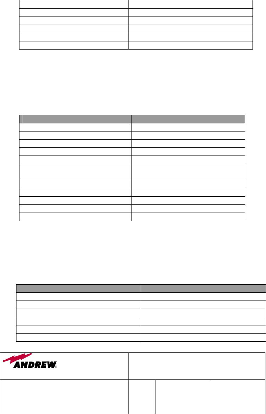
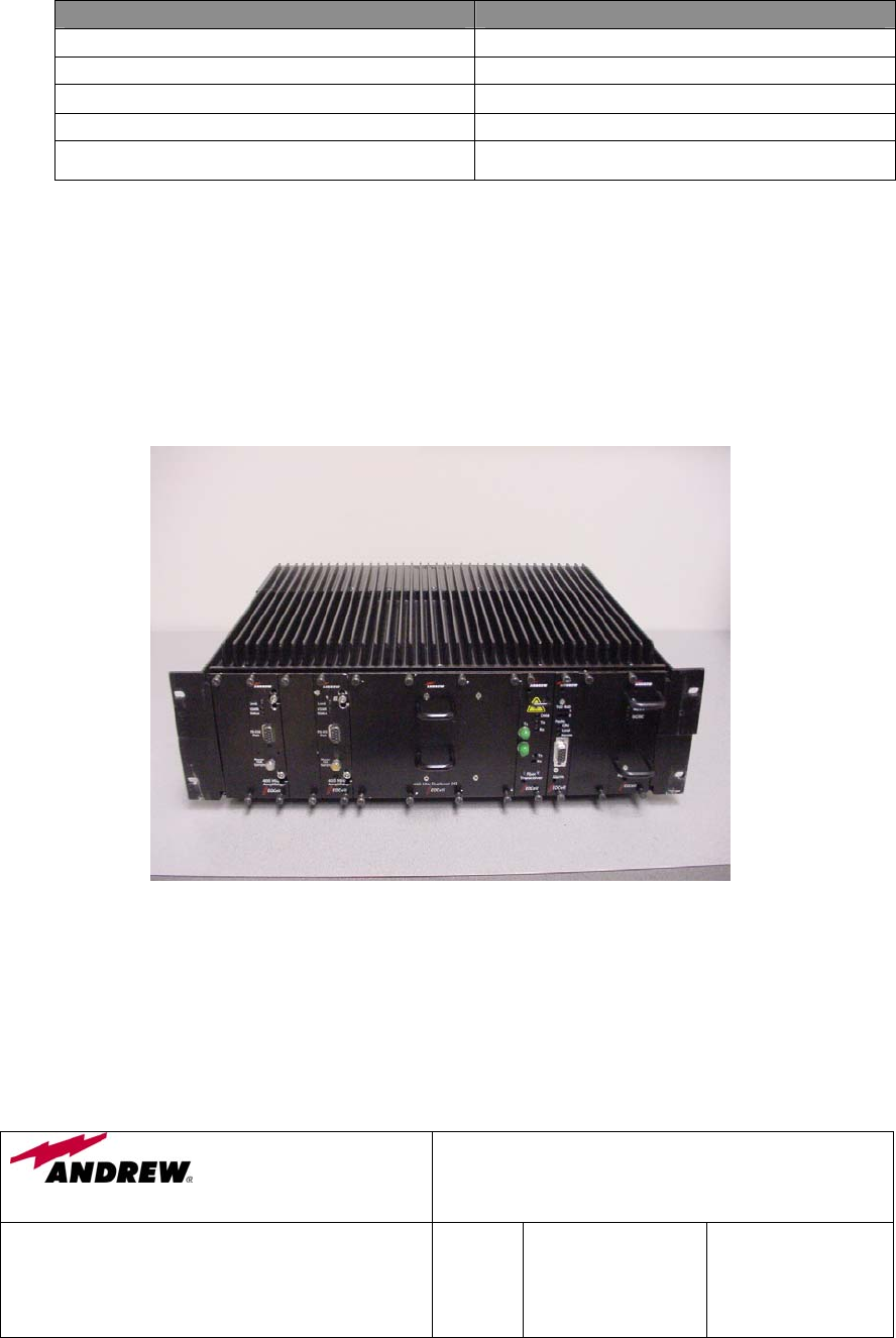
4.0 EQUIPMENT PHOTOGRAPHS
4.1 400 MHz Fiber Optic Fed Bi-Directional Amplifier
Wireless Innovations Group
2601 Telecom Parkway
Richardson, Texas 75082
400/800 MHz Fiber Optic & RF Fed Bi-Directional
Amplifier Operations / Maintenance Manual
DWG NO:
Error! Not a valid link.
Rev:
Error!
Not a
valid
link.
Date:06/16/2004 Page:
13 of 63
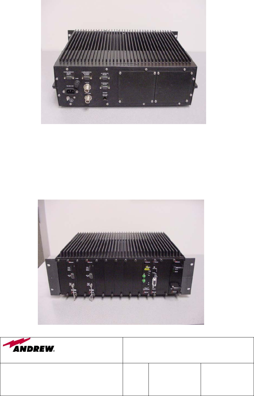
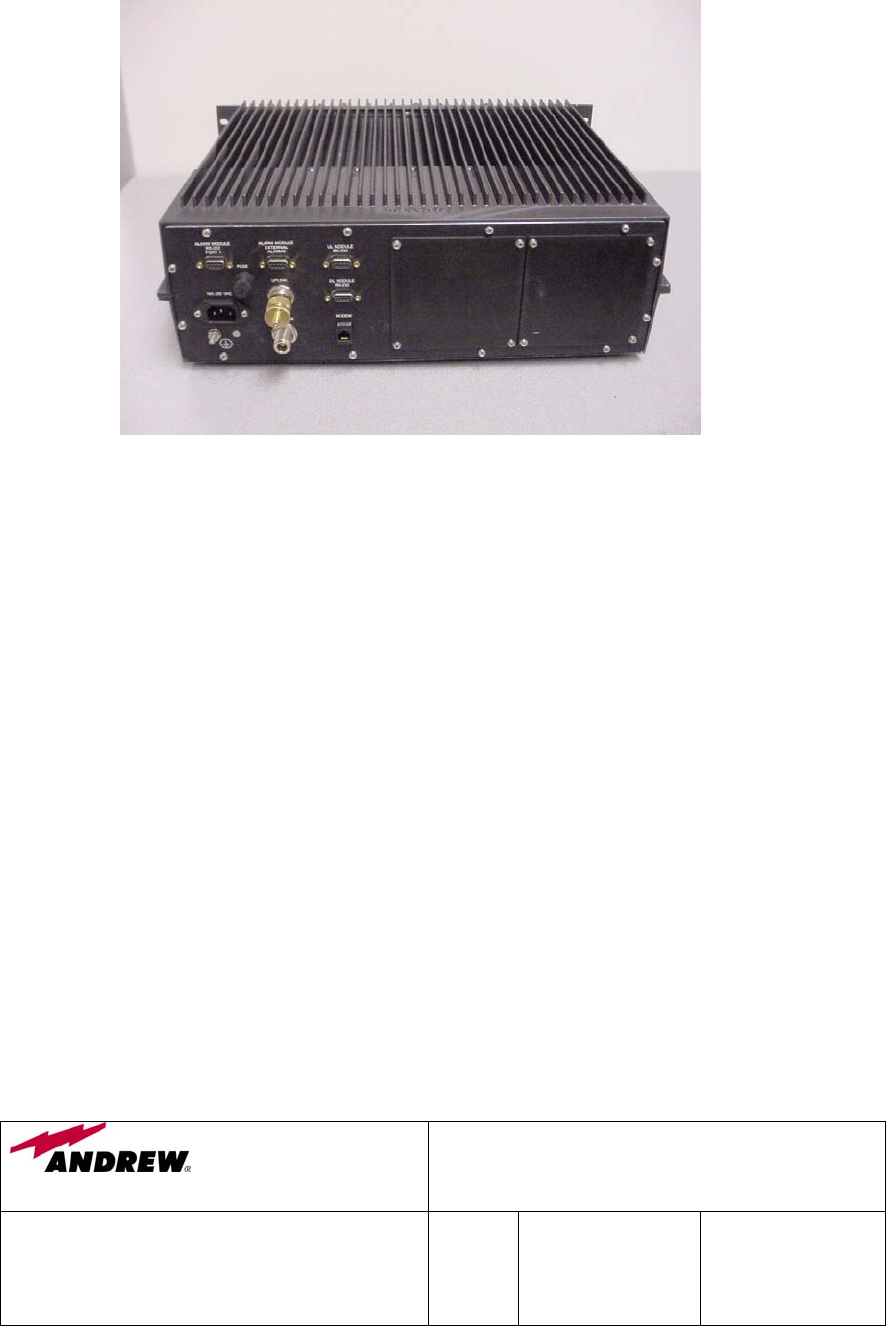
4.2 800 MHz Fiber Optic Fed Bi-Directional Amplifier
Wireless Innovations Group
2601 Telecom Parkway
Richardson, Texas 75082
400/800 MHz Fiber Optic & RF Fed Bi-Directional
Amplifier Operations / Maintenance Manual
DWG NO:
Error! Not a valid link.
Rev:
Error!
Not a
valid
link.
Date:06/16/2004 Page:
14 of 63
5.0 MODULES
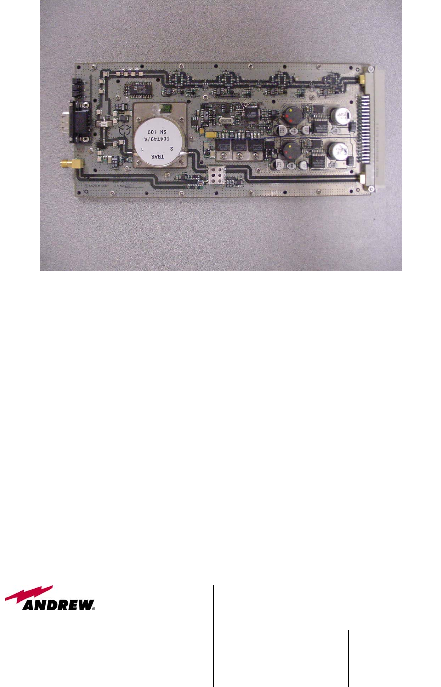
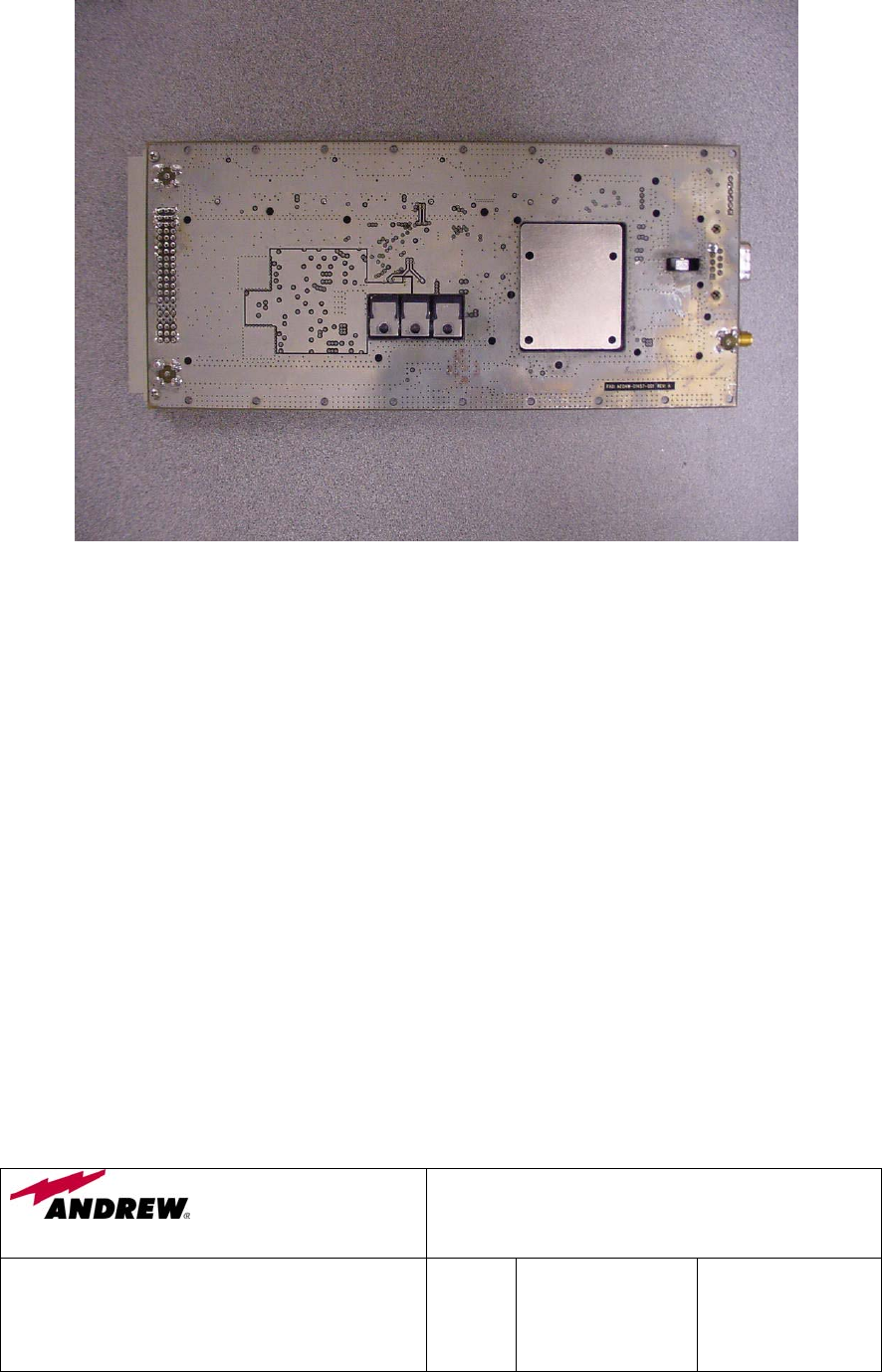
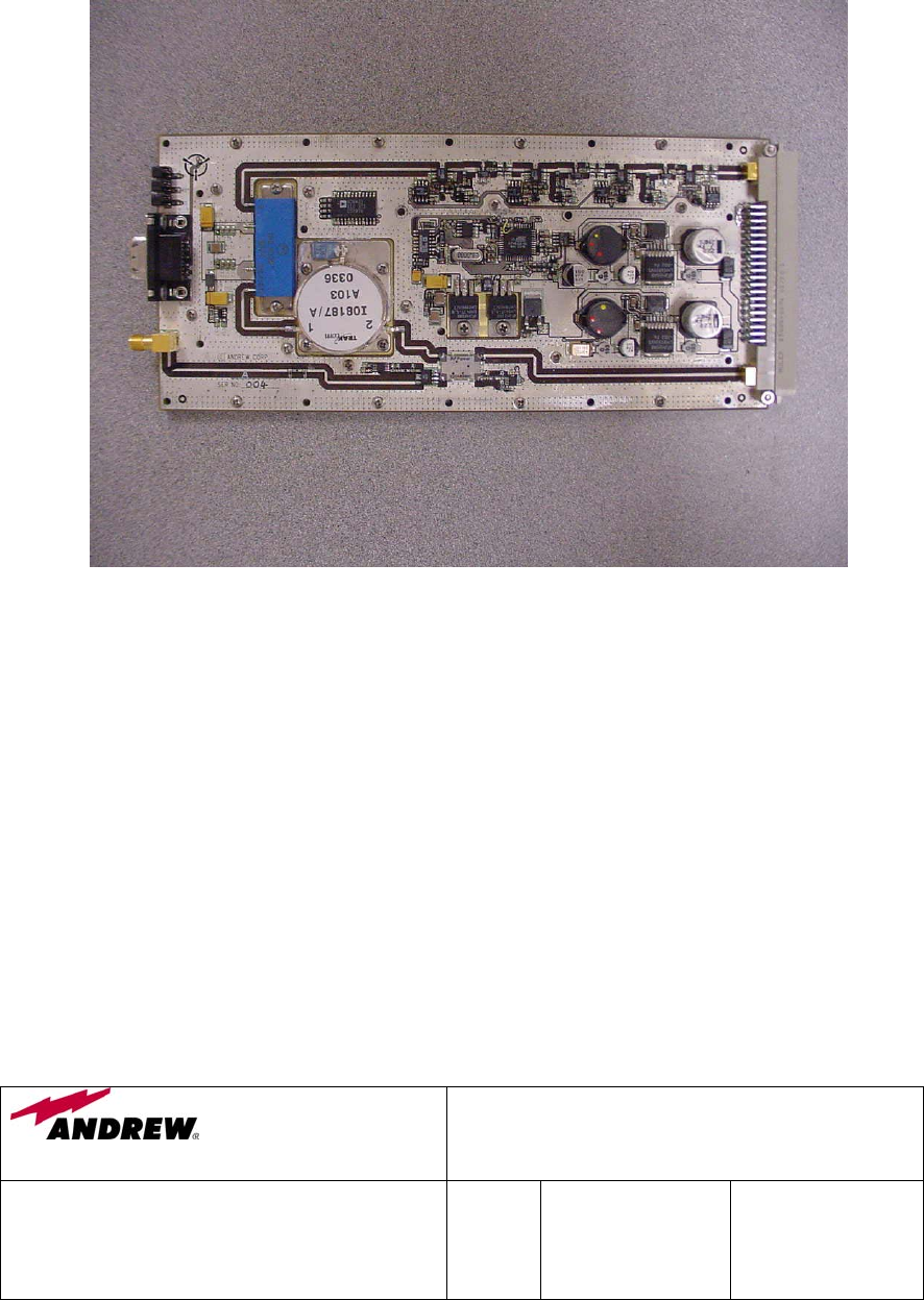
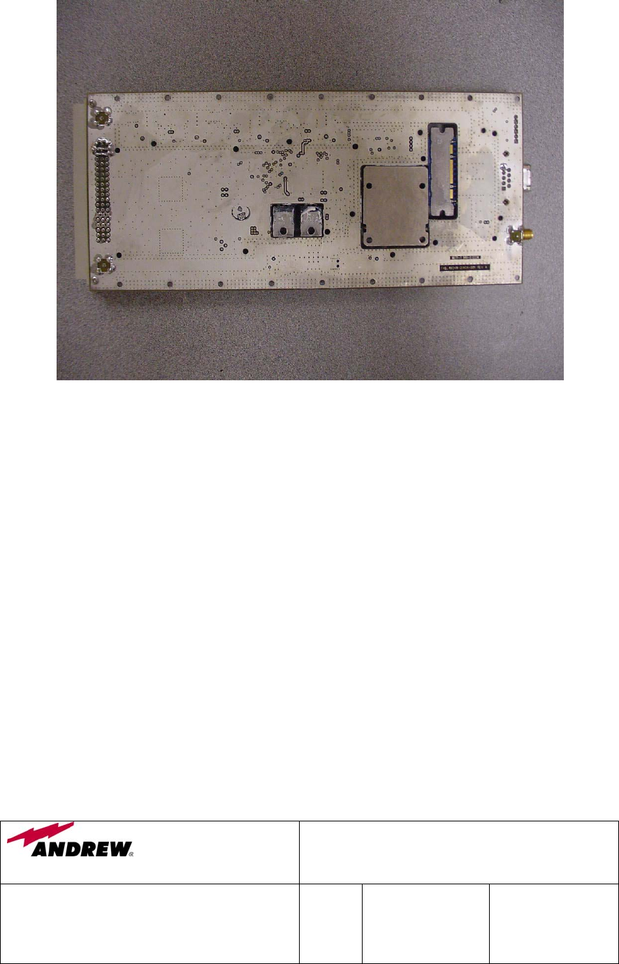
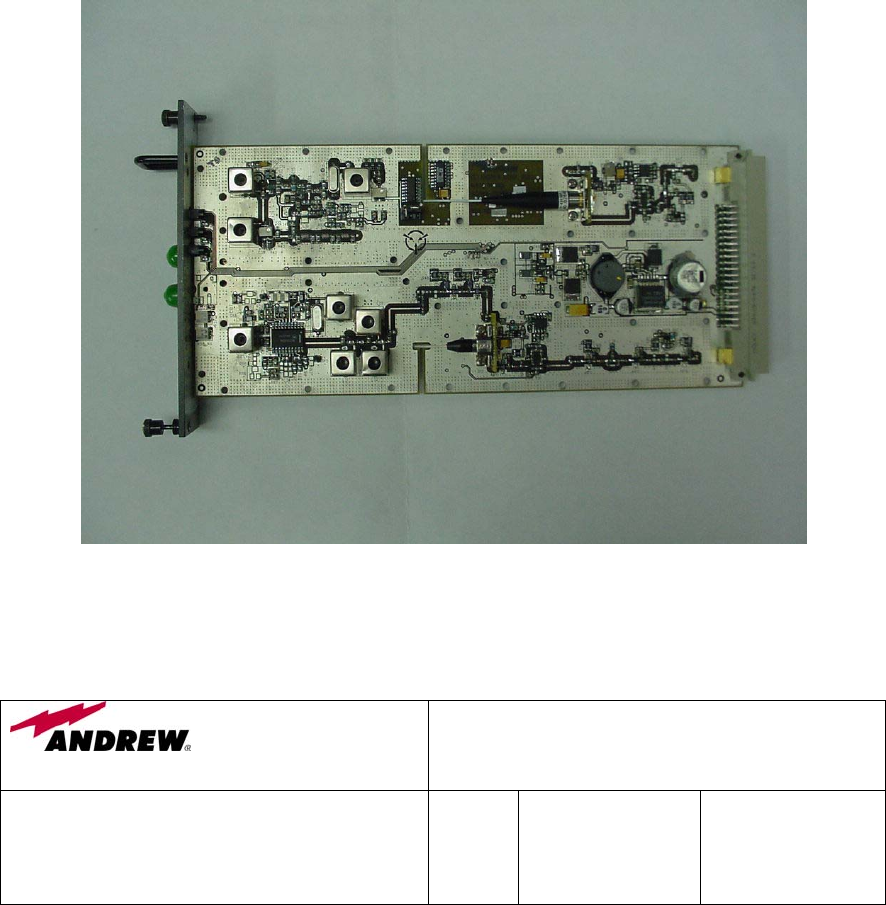
5.1 400 MHz EO Cell Amplifier Module (AE04A-D1264-001)
5.1.1 Description
This 2Watt, 483 - 487 MHz, class A Power Amplifier Module provides a nominal
52 dB of gain. It has 30 dB of gain adjustment range, which can be varied
electronically thru the front panel RS232 connector. Additionally, the module
has an internal Automatic Level Control (ALC) circuit, which can be set to limit
the maximum power level produced by the BDA. This module has an on board
RISC processor that provides optional alarming/status monitoring and
communications capabilities. The same module design is used for both the
Downlink and Uplink amplifier.
The amplifier modules contain high reliable RF parts to provide a long trouble-
free operating life. In the unlikely event of failure, the entire amplifier module
should be replaced.

Wireless Innovations Group
2601 Telecom Parkway
Richardson, Texas 75082
400/800 MHz Fiber Optic & RF Fed Bi-Directional
Amplifier Operations / Maintenance Manual
DWG NO:
Error! Not a valid link.
Rev:
Error!
Not a
valid
link.
Date:06/16/2004 Page:
15 of 63
5.1.2 Specification
PARAMETER SPECIFICATION
Operating Frequency Range
483.1625 – 486.2375 MHz
Gain Typical 51.5 dB
Output Gain Adjustment
1
30 dB
Composite Output Power ≥ +33.5 dBm
Impedance 50 Ohms
VSWR 2:1
OIP3
2
≥ + 47.5 dBm
Noise Power max. @ 51.5 dB Gain -111.5 dBm/Hz
DC Power + 48 VDC
Operating Temperature -20°C to +60°C
Note:
1.Via Front Panel RS232 Connector.
2.Two-Tone Intermodulation: Measured two-output carriers of +23.5 dBm/C at
483.1625 MHz and 483.2375 MHz with 51.5 dB gain setting.
5.1.3 Photographs
Wireless Innovations Group
2601 Telecom Parkway
Richardson, Texas 75082
400/800 MHz Fiber Optic & RF Fed Bi-Directional
Amplifier Operations / Maintenance Manual
DWG NO:
Error! Not a valid link.
Rev:
Error!
Not a
valid
link.
Date:06/16/2004 Page:
16 of 63
Wireless Innovations Group
2601 Telecom Parkway
Richardson, Texas 75082
400/800 MHz Fiber Optic & RF Fed Bi-Directional
Amplifier Operations / Maintenance Manual
DWG NO:
Error! Not a valid link.
Rev:
Error!
Not a
valid
link.
Date:06/16/2004 Page:
17 of 63

Wireless Innovations Group
2601 Telecom Parkway
Richardson, Texas 75082
400/800 MHz Fiber Optic & RF Fed Bi-Directional
Amplifier Operations / Maintenance Manual
DWG NO:
Error! Not a valid link.
Rev:
Error!
Not a
valid
link.
Date:06/16/2004 Page:
18 of 63
INTENTIONALLY LEFT BLANK

Wireless Innovations Group
2601 Telecom Parkway
Richardson, Texas 75082
400/800 MHz Fiber Optic & RF Fed Bi-Directional
Amplifier Operations / Maintenance Manual
DWG NO:
Error! Not a valid link.
Rev:
Error!
Not a
valid
link.
Date:06/16/2004 Page:
19 of 63
INTENTIONALLY LEFT BLANK

Wireless Innovations Group
2601 Telecom Parkway
Richardson, Texas 75082
400/800 MHz Fiber Optic & RF Fed Bi-Directional
Amplifier Operations / Maintenance Manual
DWG NO:
Error! Not a valid link.
Rev:
Error!
Not a
valid
link.
Date:06/16/2004 Page:
20 of 63
INTENTIONALLY LEFT BLANK

Wireless Innovations Group
2601 Telecom Parkway
Richardson, Texas 75082
400/800 MHz Fiber Optic & RF Fed Bi-Directional
Amplifier Operations / Maintenance Manual
DWG NO:
Error! Not a valid link.
Rev:
Error!
Not a
valid
link.
Date:06/16/2004 Page:
21 of 63
INTENTIONALLY LEFT BLANK

Wireless Innovations Group
2601 Telecom Parkway
Richardson, Texas 75082
400/800 MHz Fiber Optic & RF Fed Bi-Directional
Amplifier Operations / Maintenance Manual
DWG NO:
Error! Not a valid link.
Rev:
Error!
Not a
valid
link.
Date:06/16/2004 Page:
22 of 63
INTENTIONALLY LEFT BLANK

Wireless Innovations Group
2601 Telecom Parkway
Richardson, Texas 75082
400/800 MHz Fiber Optic & RF Fed Bi-Directional
Amplifier Operations / Maintenance Manual
DWG NO:
Error! Not a valid link.
Rev:
Error!
Not a
valid
link.
Date:06/16/2004 Page:
23 of 63
INTENTIONALLY LEFT BLANK

Wireless Innovations Group
2601 Telecom Parkway
Richardson, Texas 75082
400/800 MHz Fiber Optic & RF Fed Bi-Directional
Amplifier Operations / Maintenance Manual
DWG NO:
Error! Not a valid link.
Rev:
Error!
Not a
valid
link.
Date:06/16/2004 Page:
24 of 63
INTENTIONALLY LEFT BLANK

Wireless Innovations Group
2601 Telecom Parkway
Richardson, Texas 75082
400/800 MHz Fiber Optic & RF Fed Bi-Directional
Amplifier Operations / Maintenance Manual
DWG NO:
Error! Not a valid link.
Rev:
Error!
Not a
valid
link.
Date:06/16/2004 Page:
25 of 63
INTENTIONALLY LEFT BLANK

Wireless Innovations Group
2601 Telecom Parkway
Richardson, Texas 75082
400/800 MHz Fiber Optic & RF Fed Bi-Directional
Amplifier Operations / Maintenance Manual
DWG NO:
Error! Not a valid link.
Rev:
Error!
Not a
valid
link.
Date:06/16/2004 Page:
26 of 63
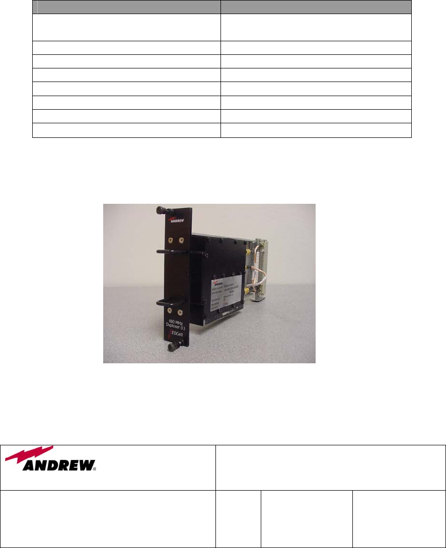
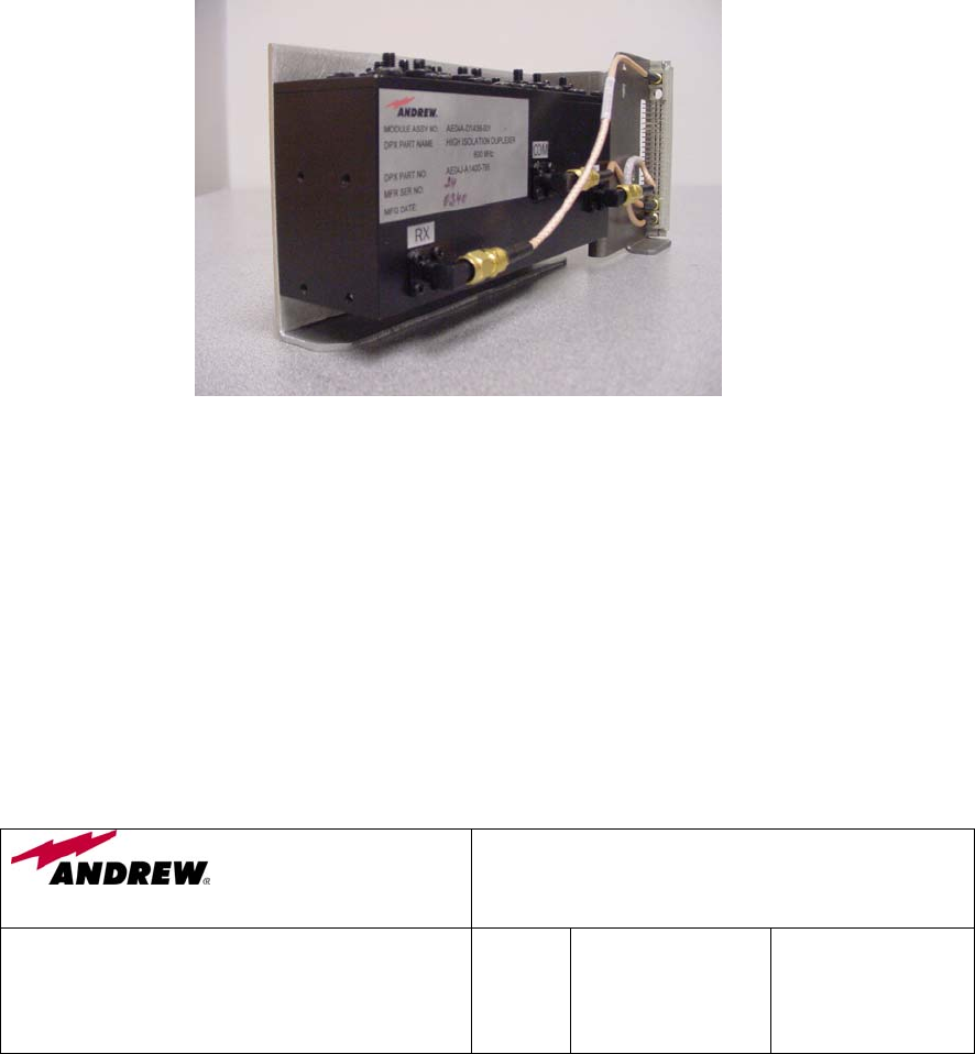
5.2 480 MHz High Isolation Duplexer (AE04A-D1442-001)
5.2.1 Description
The 480 MHz, high isolation duplexer provides the high bandpass selectivity and
isolation for the Uplink and the Downlink frequency. The duplexer is based on a
5-cavity cross-coupled bandpass filter design and is aligned carefully during
production to optimise the insertion loss, selectivity, and VSWR
The duplexer is a fully passive device and should have an extremely long trouble-
free working life and requires no maintenance. Should the duplexer be suspect of
failure, the entire duplexer module should be replaced.
5.2.2 Specification
PARAMETER SPECIFICATION
Frequency Range: Downlink
Uplink
483.1375 – 483.2625 MHz
486.1375 – 486.2625 MHz
Passband Insertion Loss 3.5 dB
Passband VSWR < 1.2:1
Impedance 50 Ohms
Power Handling 10 Watt
Downlink-To-Uplink Isolation > 96 dB @ Receive Port
Uplink-To-Downlink Isolation > 96 dB @ Transmit Port
Wireless Innovations Group
2601 Telecom Parkway
Richardson, Texas 75082
400/800 MHz Fiber Optic & RF Fed Bi-Directional
Amplifier Operations / Maintenance Manual
DWG NO:
Error! Not a valid link.
Rev:
Error!
Not a
valid
link.
Date:06/16/2004 Page:
27 of 63
Operating Temperature -20°C to +60°C
5.2.3 Photograph
5.3 480 MHz Low Isolation Duplexer (AE04A-D1443-001)
5.3.1 Description
Wireless Innovations Group
2601 Telecom Parkway
Richardson, Texas 75082
400/800 MHz Fiber Optic & RF Fed Bi-Directional
Amplifier Operations / Maintenance Manual
DWG NO:
Error! Not a valid link.
Rev:
Error!
Not a
valid
link.
Date:06/16/2004 Page:
28 of 63
The 480 MHz, low isolation duplexer provides the band selectivity and isolation
for the Uplink and the Downlink frequency. The duplexer is based on 4 ceramic
coaxial resonators design and is aligned carefully during production to optimize
the insertion loss, isolation, and VSWR
The duplexer is a fully passive device and should have an extremely long trouble-
free working life and requires no maintenance. Should the duplexer be suspect of
failure, the entire duplexer module should be replaced.
5.3.2 Specification
PARAMETER SPECIFICATION
Frequency Range: Downlink
Uplink
483.1375 – 483.2625 MHz
486.1375 – 486.2625 MHz
Passband Insertion Loss 3.5 dB
Passband VSWR < 1.2:1
Impedance 50 Ohms
Power Handling 5 Watt
Downlink-To-Uplink Isolation > 50 dB @ Receive Port
Uplink-To-Downlink Isolation > 55 dB @ Transmit Port
Operating Temperature -20°C to +60°C
5.3.3 Photograph
5.4 800 MHz EO Cell Amplifier Module (AE04A-D1265-001)
5.4.1 Description

Wireless Innovations Group
2601 Telecom Parkway
Richardson, Texas 75082
400/800 MHz Fiber Optic & RF Fed Bi-Directional
Amplifier Operations / Maintenance Manual
DWG NO:
Error! Not a valid link.
Rev:
Error!
Not a
valid
link.
Date:06/16/2004 Page:
29 of 63
This 2Watt, 821-869 MHz, class A Power Amplifier Module provides a nominally
51 dB of gain. It has 30 dB of gain adjustment range, which can be varied
electronically thru the front panel RS232 connector. Additionally, the module
has an internal Automatic Level Control (ALC) circuit, which can be set to limit
the maximum power level produced by the BDA. This module has an on board
RISC processor that provides optional alarming/status monitoring and
communications capabilities. The same module design is used for both the
Downlink and Uplink amplifier.
The amplifier module contains high reliable RF parts to provide a long trouble-
free operating life. In the unlikely event of failure, the entire amplifier module
should be replaced.
5.4.2 Specification
PARAMETER SPECIFICATION
Operating Frequency Range
821 – 869 MHz
Gain Typical 51 dB
Output Gain Adjustment
1
30 dB
Composite Output Power ≥ +33 dBm
Impedance 50 Ohms
VSWR 2:1
OIP3
2
≥ + 47 dBm
Noise Power max. @ 51 dB Gain -111 dBm/Hz
DC Power +48 VDC
Operating Temperature -20°C to +60°C
Note:
1.Via Front Panel RS232 Connector.
2.Two-Tone Intermodulation: Measure at two-output carriers of +23.5 dBm/C at
Wireless Innovations Group
2601 Telecom Parkway
Richardson, Texas 75082
400/800 MHz Fiber Optic & RF Fed Bi-Directional
Amplifier Operations / Maintenance Manual
DWG NO:
Error! Not a valid link.
Rev:
Error!
Not a
valid
link.
Date:06/16/2004 Page:
30 of 63
845 MHz and 845.6 MHz with 51 dB gain setting.
5.4.3 Photographs
Wireless Innovations Group
2601 Telecom Parkway
Richardson, Texas 75082
400/800 MHz Fiber Optic & RF Fed Bi-Directional
Amplifier Operations / Maintenance Manual
DWG NO:
Error! Not a valid link.
Rev:
Error!
Not a
valid
link.
Date:06/16/2004 Page:
31 of 63

Wireless Innovations Group
2601 Telecom Parkway
Richardson, Texas 75082
400/800 MHz Fiber Optic & RF Fed Bi-Directional
Amplifier Operations / Maintenance Manual
DWG NO:
Error! Not a valid link.
Rev:
Error!
Not a
valid
link.
Date:06/16/2004 Page:
32 of 63
5.4.4 Schematics
INTENTIONALLY LEFT BLANK

Wireless Innovations Group
2601 Telecom Parkway
Richardson, Texas 75082
400/800 MHz Fiber Optic & RF Fed Bi-Directional
Amplifier Operations / Maintenance Manual
DWG NO:
Error! Not a valid link.
Rev:
Error!
Not a
valid
link.
Date:06/16/2004 Page:
33 of 63
INTENTIONALLY LEFT BLANK

Wireless Innovations Group
2601 Telecom Parkway
Richardson, Texas 75082
400/800 MHz Fiber Optic & RF Fed Bi-Directional
Amplifier Operations / Maintenance Manual
DWG NO:
Error! Not a valid link.
Rev:
Error!
Not a
valid
link.
Date:06/16/2004 Page:
34 of 63
INTENTIONALLY LEFT BLANK

Wireless Innovations Group
2601 Telecom Parkway
Richardson, Texas 75082
400/800 MHz Fiber Optic & RF Fed Bi-Directional
Amplifier Operations / Maintenance Manual
DWG NO:
Error! Not a valid link.
Rev:
Error!
Not a
valid
link.
Date:06/16/2004 Page:
35 of 63
INTENTIONALLY LEFT BLANK

Wireless Innovations Group
2601 Telecom Parkway
Richardson, Texas 75082
400/800 MHz Fiber Optic & RF Fed Bi-Directional
Amplifier Operations / Maintenance Manual
DWG NO:
Error! Not a valid link.
Rev:
Error!
Not a
valid
link.
Date:06/16/2004 Page:
36 of 63
INTENTIONALLY LEFT BLANK

Wireless Innovations Group
2601 Telecom Parkway
Richardson, Texas 75082
400/800 MHz Fiber Optic & RF Fed Bi-Directional
Amplifier Operations / Maintenance Manual
DWG NO:
Error! Not a valid link.
Rev:
Error!
Not a
valid
link.
Date:06/16/2004 Page:
37 of 63
INTENTIONALLY LEFT BLANK

Wireless Innovations Group
2601 Telecom Parkway
Richardson, Texas 75082
400/800 MHz Fiber Optic & RF Fed Bi-Directional
Amplifier Operations / Maintenance Manual
DWG NO:
Error! Not a valid link.
Rev:
Error!
Not a
valid
link.
Date:06/16/2004 Page:
38 of 63
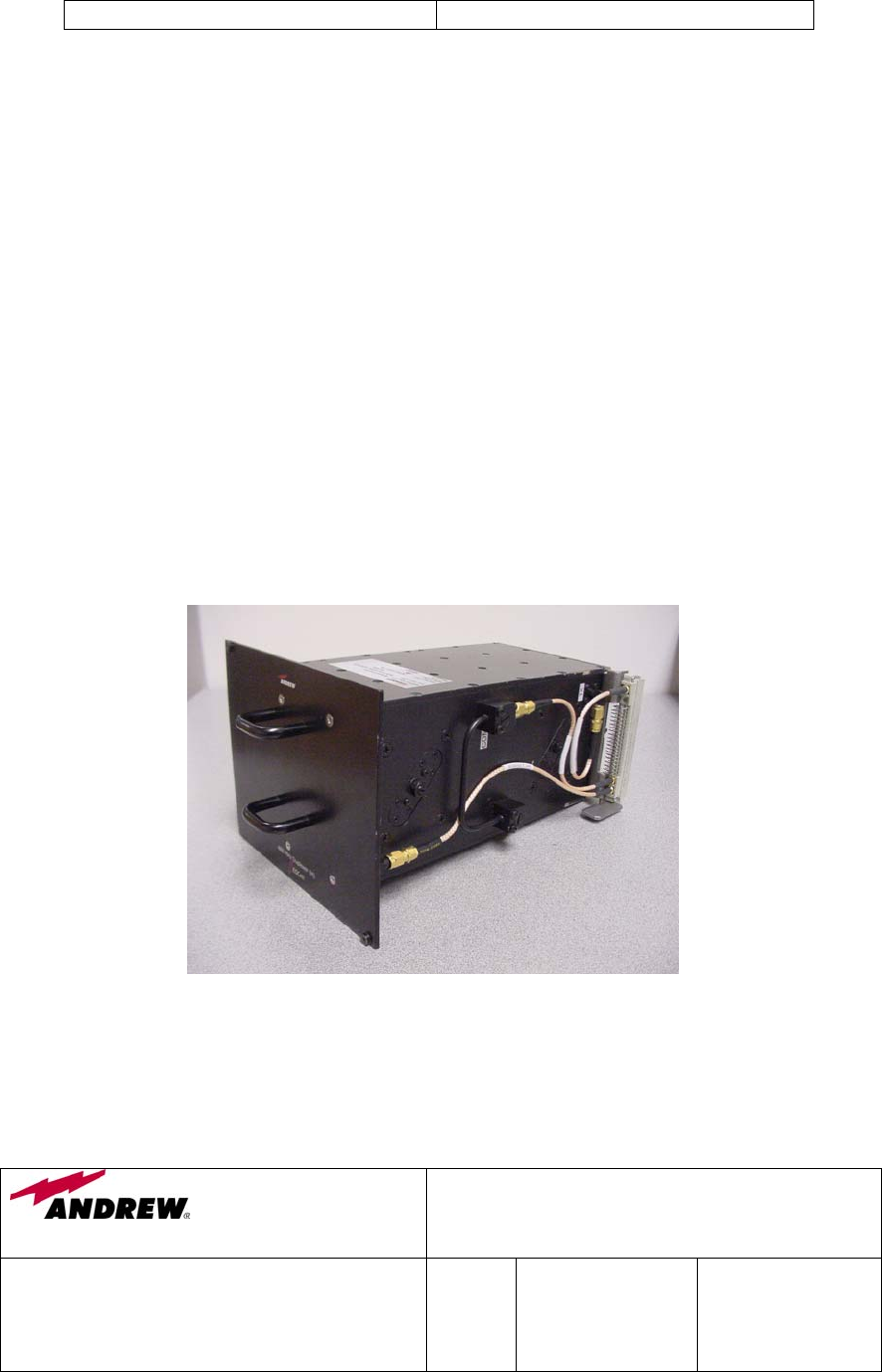
5.5 800 MHz High Isolation Duplexer (AE04A-D1438-001)
5.5.1 Description
The 800 MHz, high isolation duplexer provides the high bandpass selectivity and
isolation for the Uplink and the Downlink frequency. The duplexer is based on a
5-cavity cross-coupled bandpass filter design and is aligned carefully during
production to optimize the insertion loss, selectivity, and VSWR
The duplexer is a fully passive device and should have an extremely long trouble-
free working life and requires no maintenance. Should the duplexer be suspect of
failure, the entire duplexer module should be replaced.
5.5.2 Specification
PARAMETER SPECIFICATION
Frequency Range: Downlink
Uplink
866 – 869 MHz
821 – 824 MHz
Passband Insertion Loss 1 dB
Passband VSWR < 1.2:1
Impedance 50 Ohms
Power Handling 10 Watt
Downlink-To-Uplink Isolation > 96 dB @ Receive Port
Uplink-To-Downlink Isolation > 96 dB @ Transmit Port
Operating Temperature -20°C to +60°C
Wireless Innovations Group
2601 Telecom Parkway
Richardson, Texas 75082
400/800 MHz Fiber Optic & RF Fed Bi-Directional
Amplifier Operations / Maintenance Manual
DWG NO:
Error! Not a valid link.
Rev:
Error!
Not a
valid
link.
Date:06/16/2004 Page:
39 of 63
5.5.3 Photograph
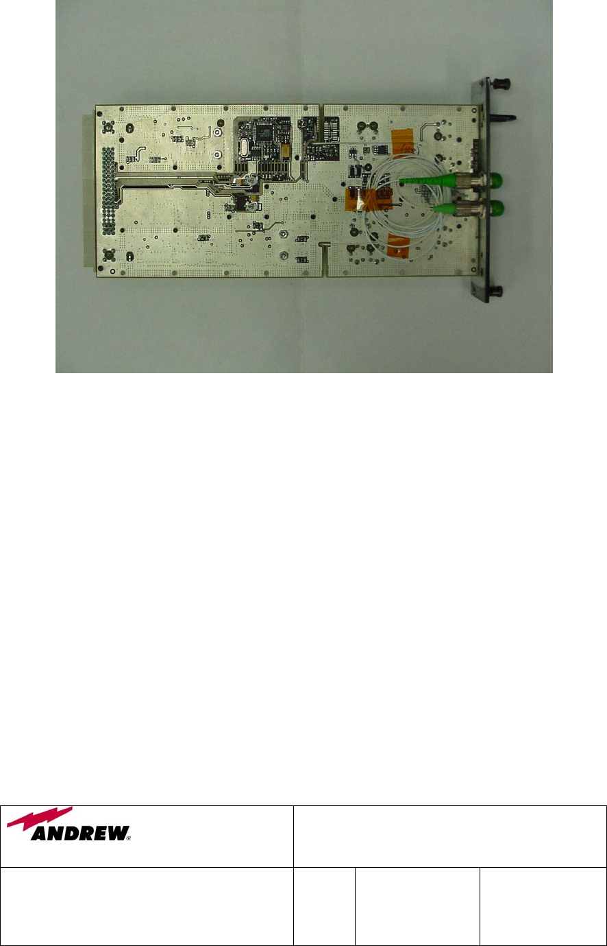
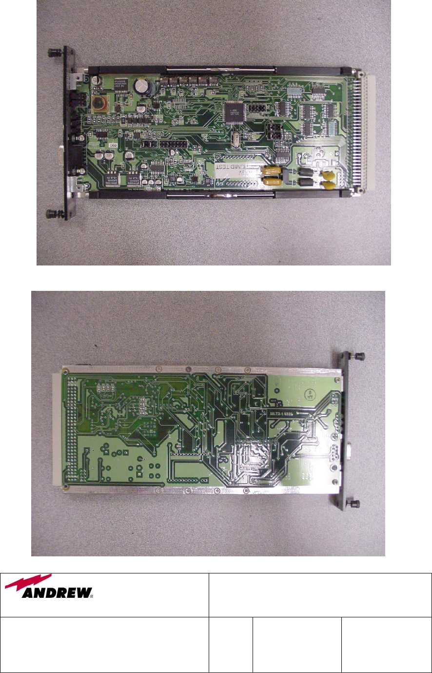
5.6 Fiber Optic Transceiver Module (AE04A-D1100-009)
5.6.1 Description
The Fiber Optic Transceiver Module converts the Downlink and Uplink electrical
(RF) signals into optical signals prior to routing the signals between remote BDAs
and the base transceiver station. The fiber optic transceiver is capable of
providing up to 18 dB of RF gain. So for fiber optic links with 9 dB or less of
optical loss, the fiber transceiver can negate that loss and in turn provide a fiber
link that is lossless. During the BDA setup, the fiber optic link is set to 0 dB.
Wireless Innovations Group
2601 Telecom Parkway
Richardson, Texas 75082
400/800 MHz Fiber Optic & RF Fed Bi-Directional
Amplifier Operations / Maintenance Manual
DWG NO:
Error! Not a valid link.
Rev:
Error!
Not a
valid
link.
Date:06/16/2004 Page:
40 of 63
The fiber optic transceiver module has an on board RISC processor that provides
optional alarming/status monitoring and communications capability. The fiber
transceiver is also equipped with high reliable parts to provide a long trouble-free
operating life. Should the module be suspect of failure, the entire module should
be replaced. Note, due to the possibility of laser radiation hazard, the fiber optic
transceiver module cover should never be removed to troubleshoot or to adjust the
laser optical power.
5.6.2 Specification
OPTICAL PARAMETER SPECIFICATION
Maximum Optical Link Loss
9 dBo
Wavelength 1310+30 nm
Laser Type DFB, single-mode
Optical Output Power > 2 mW
Optical Return Loss > -60 dB
Connector Style
FC/APC post-fix
FC/APC
RF PARAMETER SPECIFICATION
Frequency Range
483-870 MHz
Link Gain 0 dB nominal
18 dB Front panel adjustable
Link Noise Figure 58 dB typical
1 dB Compression Point ≥ + 13 dBm typical
Input Third Order Intercept Point ≥ + 26 dBm minimum
Spur Free Dynamic Range 95 dB/Hz
Data Link Related Spurs Levels > -70 dBc and 32 MHz from any
desired signal
Power Supply Switching Noise < -80 dBc
Operating Temperature -20°C to +60°C
Wireless Innovations Group
2601 Telecom Parkway
Richardson, Texas 75082
400/800 MHz Fiber Optic & RF Fed Bi-Directional
Amplifier Operations / Maintenance Manual
DWG NO:
Error! Not a valid link.
Rev:
Error!
Not a
valid
link.
Date:06/16/2004 Page:
41 of 63
5.6.3 Photographs
Wireless Innovations Group
2601 Telecom Parkway
Richardson, Texas 75082
400/800 MHz Fiber Optic & RF Fed Bi-Directional
Amplifier Operations / Maintenance Manual
DWG NO:
Error! Not a valid link.
Rev:
Error!
Not a
valid
link.
Date:06/16/2004 Page:
42 of 63
5.6.4 Schematics
INTENTIONALLY LEFT BLANK

Wireless Innovations Group
2601 Telecom Parkway
Richardson, Texas 75082
400/800 MHz Fiber Optic & RF Fed Bi-Directional
Amplifier Operations / Maintenance Manual
DWG NO:
Error! Not a valid link.
Rev:
Error!
Not a
valid
link.
Date:06/16/2004 Page:
43 of 63

Wireless Innovations Group
2601 Telecom Parkway
Richardson, Texas 75082
400/800 MHz Fiber Optic & RF Fed Bi-Directional
Amplifier Operations / Maintenance Manual
DWG NO:
Error! Not a valid link.
Rev:
Error!
Not a
valid
link.
Date:06/16/2004 Page:
44 of 63
INTENTIONALLY LEFT BLANK

Wireless Innovations Group
2601 Telecom Parkway
Richardson, Texas 75082
400/800 MHz Fiber Optic & RF Fed Bi-Directional
Amplifier Operations / Maintenance Manual
DWG NO:
Error! Not a valid link.
Rev:
Error!
Not a
valid
link.
Date:06/16/2004 Page:
45 of 63
INTENTIONALLY LEFT BLANK

Wireless Innovations Group
2601 Telecom Parkway
Richardson, Texas 75082
400/800 MHz Fiber Optic & RF Fed Bi-Directional
Amplifier Operations / Maintenance Manual
DWG NO:
Error! Not a valid link.
Rev:
Error!
Not a
valid
link.
Date:06/16/2004 Page:
46 of 63
INTENTIONALLY LEFT BLANK

Wireless Innovations Group
2601 Telecom Parkway
Richardson, Texas 75082
400/800 MHz Fiber Optic & RF Fed Bi-Directional
Amplifier Operations / Maintenance Manual
DWG NO:
Error! Not a valid link.
Rev:
Error!
Not a
valid
link.
Date:06/16/2004 Page:
47 of 63
INTENTIONALLY LEFT BLANK

Wireless Innovations Group
2601 Telecom Parkway
Richardson, Texas 75082
400/800 MHz Fiber Optic & RF Fed Bi-Directional
Amplifier Operations / Maintenance Manual
DWG NO:
Error! Not a valid link.
Rev:
Error!
Not a
valid
link.
Date:06/16/2004 Page:
48 of 63
INTENTIONALLY LEFT BLANK

Wireless Innovations Group
2601 Telecom Parkway
Richardson, Texas 75082
400/800 MHz Fiber Optic & RF Fed Bi-Directional
Amplifier Operations / Maintenance Manual
DWG NO:
Error! Not a valid link.
Rev:
Error!
Not a
valid
link.
Date:06/16/2004 Page:
49 of 63
INTENTIONALLY LEFT BLANK

Wireless Innovations Group
2601 Telecom Parkway
Richardson, Texas 75082
400/800 MHz Fiber Optic & RF Fed Bi-Directional
Amplifier Operations / Maintenance Manual
DWG NO:
Error! Not a valid link.
Rev:
Error!
Not a
valid
link.
Date:06/16/2004 Page:
50 of 63
INTENTIONALLY LEFT BLANK

Wireless Innovations Group
2601 Telecom Parkway
Richardson, Texas 75082
400/800 MHz Fiber Optic & RF Fed Bi-Directional
Amplifier Operations / Maintenance Manual
DWG NO:
Error! Not a valid link.
Rev:
Error!
Not a
valid
link.
Date:06/16/2004 Page:
51 of 63
INTENTIONALLY LEFT BLANK
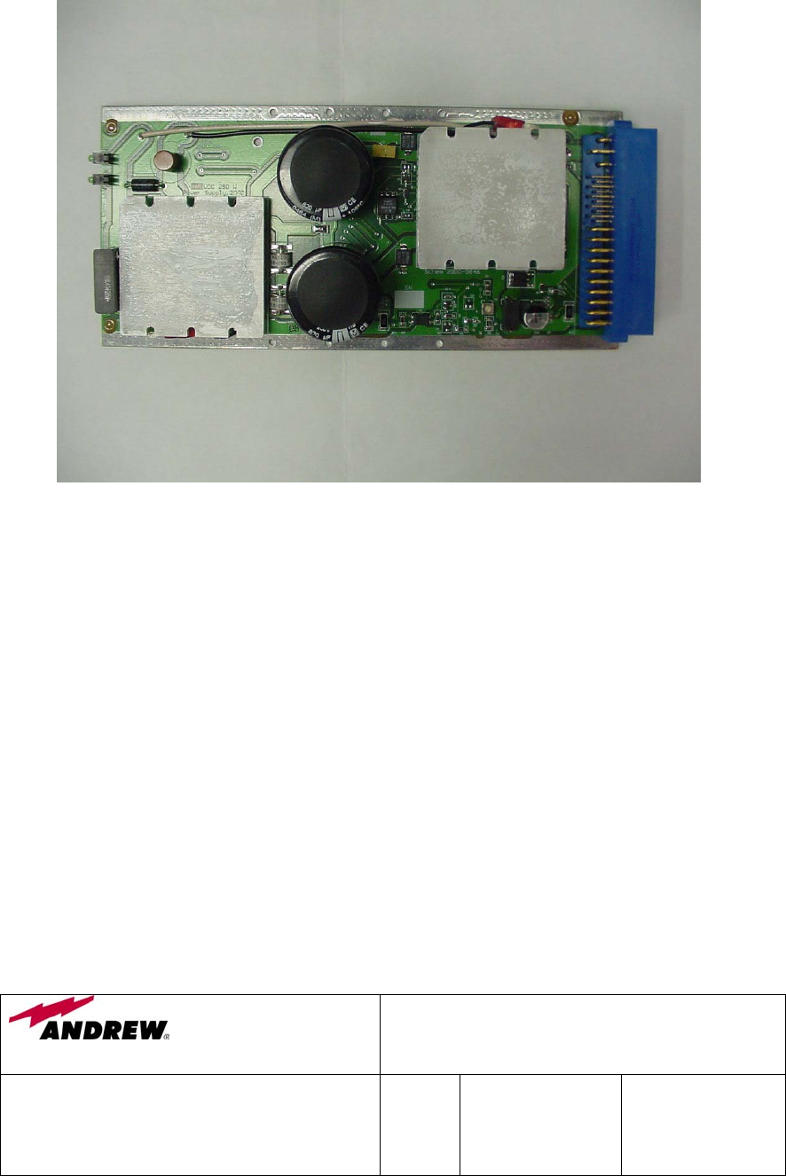
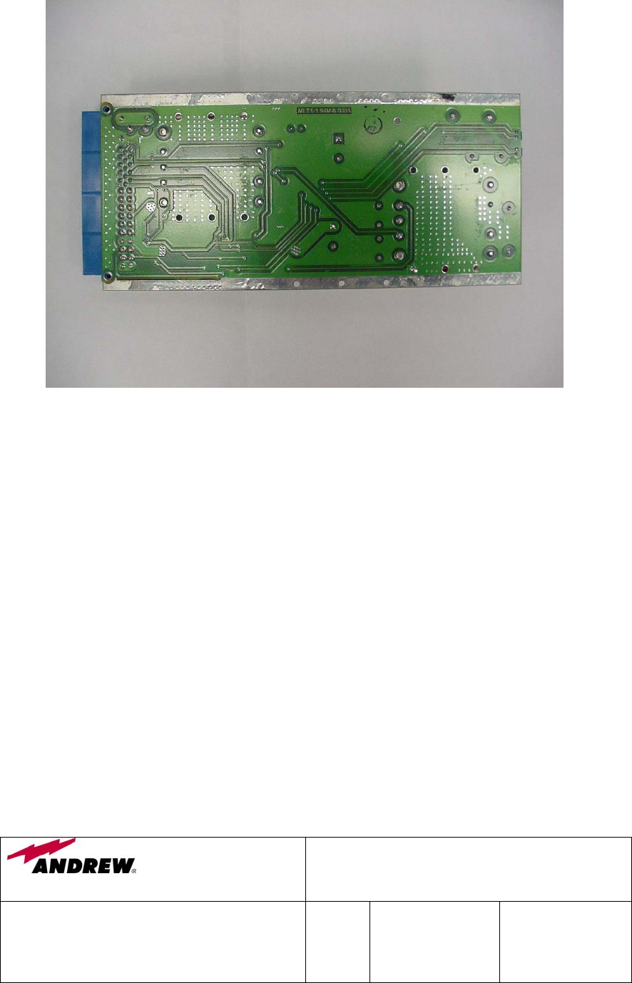
5.7 +48V Power Supply Module (AE04A-D0803-002)

Wireless Innovations Group
2601 Telecom Parkway
Richardson, Texas 75082
400/800 MHz Fiber Optic & RF Fed Bi-Directional
Amplifier Operations / Maintenance Manual
DWG NO:
Error! Not a valid link.
Rev:
Error!
Not a
valid
link.
Date:06/16/2004 Page:
52 of 63
5.7.1 Description
The AC to DC Power Supply Module provides + 48VDC from the main AC
source to the BDA Chassis. The power supply module contains an AC front-end
FARM (Filter/Autoranging Rectifier Module) followed by a DC-DC Converter
Module. The AC to DC power supply module is capable of interfacing directly
with various sources of AC power. The power supply module is equipped with a
EMI filter, a autorange line rectifier and a inrush current limiting circuit.
In the unlikely event of failure, the entire power supply module should be
replaced.
5.7.2 Specification
PARAMETER SPECIFICATION
Input Voltage
115/230 VAC Autoranging
Output Voltage +48V
Output Current 5.2 Amps
Output Power 250 Watts
Operating Temperature -20°C to +60°C
Wireless Innovations Group
2601 Telecom Parkway
Richardson, Texas 75082
400/800 MHz Fiber Optic & RF Fed Bi-Directional
Amplifier Operations / Maintenance Manual
DWG NO:
Error! Not a valid link.
Rev:
Error!
Not a
valid
link.
Date:06/16/2004 Page:
53 of 63
5.7.3 Photographs
Wireless Innovations Group
2601 Telecom Parkway
Richardson, Texas 75082
400/800 MHz Fiber Optic & RF Fed Bi-Directional
Amplifier Operations / Maintenance Manual
DWG NO:
Error! Not a valid link.
Rev:
Error!
Not a
valid
link.
Date:06/16/2004 Page:
54 of 63
5.7.4 Schematics
INTENTIONALLY LEFT BLANK

Wireless Innovations Group
2601 Telecom Parkway
Richardson, Texas 75082
400/800 MHz Fiber Optic & RF Fed Bi-Directional
Amplifier Operations / Maintenance Manual
DWG NO:
Error! Not a valid link.
Rev:
Error!
Not a
valid
link.
Date:06/16/2004 Page:
55 of 63
5.8 Alarm Module (AE04A-D0805-007): Optional
5.8.1 Description
The optional Alarm Module serves as a communication processor to provide a
single point of monitoring interface for all the modules within the Fiber Optical
Fed BDA. The summary alarm/monitoring status of each module can then be
provided over Alarm Module’s RS-232 interface or sent thru the Fiber Optic
Transceiver Module to a remote control location.
In the unlikely event of failure, the entire Alarm Module should be replaced.
5.8.2 Photographs
Wireless Innovations Group
2601 Telecom Parkway
Richardson, Texas 75082
400/800 MHz Fiber Optic & RF Fed Bi-Directional
Amplifier Operations / Maintenance Manual
DWG NO:
Error! Not a valid link.
Rev:
Error!
Not a
valid
link.
Date:06/16/2004 Page:
56 of 63

Wireless Innovations Group
2601 Telecom Parkway
Richardson, Texas 75082
400/800 MHz Fiber Optic & RF Fed Bi-Directional
Amplifier Operations / Maintenance Manual
DWG NO:
Error! Not a valid link.
Rev:
Error!
Not a
valid
link.
Date:06/16/2004 Page:
57 of 63
5.8.3 Schematics

Wireless Innovations Group
2601 Telecom Parkway
Richardson, Texas 75082
400/800 MHz Fiber Optic & RF Fed Bi-Directional
Amplifier Operations / Maintenance Manual
DWG NO:
Error! Not a valid link.
Rev:
Error!
Not a
valid
link.
Date:06/16/2004 Page:
58 of 63
INTENTIONALLY LEFT BLANK

Wireless Innovations Group
2601 Telecom Parkway
Richardson, Texas 75082
400/800 MHz Fiber Optic & RF Fed Bi-Directional
Amplifier Operations / Maintenance Manual
DWG NO:
Error! Not a valid link.
Rev:
Error!
Not a
valid
link.
Date:06/16/2004 Page:
59 of 63
INTENTIONALLY LEFT BLANK

Wireless Innovations Group
2601 Telecom Parkway
Richardson, Texas 75082
400/800 MHz Fiber Optic & RF Fed Bi-Directional
Amplifier Operations / Maintenance Manual
DWG NO:
Error! Not a valid link.
Rev:
Error!
Not a
valid
link.
Date:06/16/2004 Page:
60 of 63
INTENTIONALLY LEFT BLANK

Wireless Innovations Group
2601 Telecom Parkway
Richardson, Texas 75082
400/800 MHz Fiber Optic & RF Fed Bi-Directional
Amplifier Operations / Maintenance Manual
DWG NO:
Error! Not a valid link.
Rev:
Error!
Not a
valid
link.
Date:06/16/2004 Page:
61 of 63
INTENTIONALLY LEFT BLANK
6. INSTALLATION
6.1 BDA Installation & Gain Setup
INSTALLATION
1 Install the BDA in a standard 19” rack. The BDA should be placed in a location where
the interconnect cables (i.e. fiber, RF and serial cable) can be easily installed and not
susceptible to damage. If the BDA is not installed in a controlled environment, a 5U high
space should be located above and below the unit for airflow.
Wireless Innovations Group
2601 Telecom Parkway
Richardson, Texas 75082
400/800 MHz Fiber Optic & RF Fed Bi-Directional
Amplifier Operations / Maintenance Manual
DWG NO:
Error! Not a valid link.
Rev:
Error!
Not a
valid
link.
Date:06/16/2004 Page:
62 of 63
2 Plug the BDA into a 120 VAC single phase three wire grounded receptacle (5-15R).
3 Connect the RF antenna cable to the antenna port (Type-N Female) on the rear panel of
the BDA. If a RF fed BDA was installed, connect the base station RF cable to the base
station port (Type-N Female) on the rear panel of the BDA.
4 If a fiber fed BDA was installed, connect the fiber optic cable to the BDA front panel
FC/APC connectors. If both fiber connection indicators (i.e. LEDs) are illuminating a
green color, the connection between the optical source and the BDA was successful.
DOWNLINK GAIN SETUP
The fiber fed BDA provides 18 dB of gain for 9 dB of optical loss. The factory gain
setting for the fiber fed BDA is 48 dB, with a maximum FCC RF output limit of +30
dBm. Due to the various fiber optic link losses found in a communication system, the
fiber optic gain must be adjusted so not to exceed the BDA FCC power limit. The
equipment needed and the gain test setup required for this adjustment is shown in Figure
6.1 below.
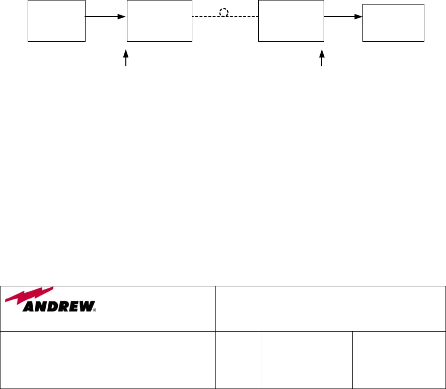
Figure 6.1 Downlink Gain Test Configuration
1 Using the signal generator, inject a –18 dBm signal into the downlink operating passband
of the fiber fed BDA.
2 Measure the output signal level of the fiber fed BDA using the spectrum analyzer.
3 If the measured output signal level exceeds +30 dBm, reduce the fiber optic gain (i.e.
adjust BDA’s fiber optic transceiver front panel potentiometer) so that the output power
level is equal to +30 dBm.
NOTE: No additional fiber gain adjustment will be required after the fiber optic gain has
been set. If any additional gain adjustments are required they must be performed via the
RS232 port.
Signal
Generator
Fiber Optic
Transceiver
Chassis
Fiber Fed
BDA
Spectrum
Analyzer
-18 dBm
RF Cable Fiber Cable RF Cable
+30 dBm
Wireless Innovations Group
2601 Telecom Parkway
Richardson, Texas 75082
400/800 MHz Fiber Optic & RF Fed Bi-Directional
Amplifier Operations / Maintenance Manual
DWG NO:
Error! Not a valid link.
Rev:
Error!
Not a
valid
link.
Date:06/16/2004 Page:
63 of 63
The RF fed BDA gain setting is performed at the factory and no field adjustments are
required. With a 48 dB factory gain setting, the maximum input signal level is –18 dBm.
This input level will ensure that FCC power limit (+30 dBm) is not exceeded.
UPLINK GAIN SETUP
The fiber fed BDA provides 18 dB of gain for 9 dB of optical loss. The factory gain
setting for the fiber fed BDA is 48 dB. Due to the various fiber optic link losses found in
a communication system, the uplink fiber optic gain must be adjusted so not to overdrive
the fiber optic link when high power transmitters are operating near the BDA. The
equipment needed and the gain test setup required for this adjustment is shown in Figure
6.2 below.
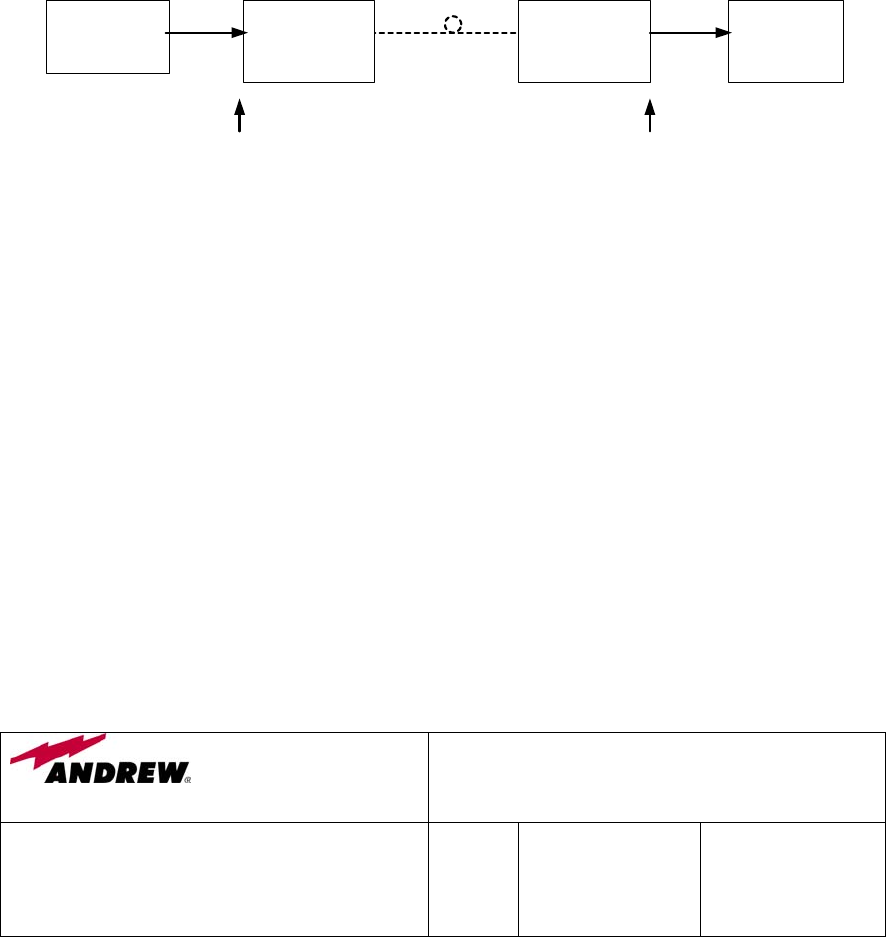
Figure 6.2 Uplink Gain Test Configuration
1 Using the signal generator, inject a – 43 dBm signal into the uplink operating passband of
the fiber fed BDA.
2 Measure the output signal level of the fiber optic transceiver chassis (i.e. located near the
base receiver station) using the spectrum analyzer.
3 If the measured output signal level exceeds – 4 dBm, reduce the fiber optic gain (i.e.
adjust fiber optic transceiver front panel potentiometer) so that the output power level is
equal to - 4 dBm.
NOTE: No additional fiber gain adjustment will be required after the fiber optic gain has
been set. If any additional gain adjustments are required they must be performed via the
RS232 port.
Spectrum
Analyzer
Fiber Optic
Transceiver
Chassis
Fiber Fed
BDA
Signal
Generator
Fiber CableRF Cable RF Cable
- 4 dBm-43 dBm

Wireless Innovations Group
2601 Telecom Parkway
Richardson, Texas 75082
400/800 MHz Fiber Optic & RF Fed Bi-Directional
Amplifier Operations / Maintenance Manual
DWG NO:
Error! Not a valid link.
Rev:
Error!
Not a
valid
link.
Date:06/16/2004 Page:
64 of 63
The RF fed BDA uplink gain setting was performed at the factory and no field adjustments are
required. For a 48 dB gain setting, the maximum input signal level is – 14 dBm with ALC
active and – 43 dBm without ALC active. Note, the ALC is activated at the factory and when
the input level exceeds – 43 dBm, the ALC will go into operation.
7. BDA MAINTENANCE / TROUBLESHOOTING & MODULE CARE
7.1 Maintenance
The BDA does not require any routine or preventative maintenance once in operation.
7.2 BDA Troubleshooting Procedure
FAULT Troubleshooting Procedure
No Downlink Signal -Verify BDA power is switched “ON”.
-Check fiber fed BDA cable connections.
-Check RF fed BDA cable connections.
-Verify fiber fed BDA Rx fiber port LED is green.
-Check Radio Transmitter at base station.
No Uplink Signal -Verify BDA power is switched “ON”.
-Check fiber fed BDA cable connections.
-Check RF fed BDA cable connections.
-Check fiber optic connection at base station Fiber Optic
Transceiver Chassis.
-Check for output signal at Fiber Optic Transceiver
Chassis located at the base station.
Low FF BDA Downlink Gain
(Gain Set: 48 dB)
-Using a Signal Generator, inject a –18 dBm signal at base
fiber optic transceiver and measure output power level of
BDA with Spectrum Analyzer (+30 dBm).
Low RF BDA Downlink Gain
(Gain Set: 48 dB)
-Using a Signal Generator, inject a – 18 dBm signal in the
base station port of the BDA and measure the output
power level of BDA with Spectrum Analyzer (+30 dBm).
Low FF BDA Uplink Gain
(Gain Set: 48 dB)
-Using a Signal Generator, inject a – 43 dBm signal at the
BDA antenna port and measure the output power level at
the Fiber Optic Transciever Chassis at the base station port
using the Spectrum Analyzer (- 4 dBm).
Low RF BDA Uplink Gain
(Gain Set: 48 dB)
-Using a Signal Generator, inject a – 43 dBm signal at the
BDA antenna port and measure the output power level at
the BDA base station port using the Spectrum Analyzer
(+ 5 dBm).
7.3 Tools & Test Equipment

Wireless Innovations Group
2601 Telecom Parkway
Richardson, Texas 75082
400/800 MHz Fiber Optic & RF Fed Bi-Directional
Amplifier Operations / Maintenance Manual
DWG NO:
Error! Not a valid link.
Rev:
Error!
Not a
valid
link.
Date:06/16/2004 Page:
65 of 63
The minimum tools and test equipment listed below are needed to successfully service the
BDA:
Spectrum Analyzer: 100kHz to 2GHz
Signal Generator: 30MHz to 2GHz
Attenuator: 20dB, 10W, DC-2GHz, (N male – N female)
Optical Meter: Universal Volt-Watts
Test cable x 2: N male – N male, 2M long RG214
Test cable x 2: SMA male – N male, 1m long RG223
Hand tools: Philips tip screwdriver
SMA torque wrench
7.4 Module Care
The EOCell Amplifier module, Fiber Optic Transceiver module +48V Power Supply module
and optional Alarm module contain semiconductor devices that are susceptible to damage
from electrostatic discharge (ESD). Correct handling of modules is mandatory to ensure
long-term reliability.
Furthermore, to prevent electrical damage to modules during the removal or installation
process, disconnect the BDA from the AC power source.
7.4.1 Module Removal
1 Verify that AC power to the BDA has been removed.
2 Disconnect the system RF or fiber optic cable as required.
3 Loosen the module’s top and bottom wedge locks using a 9/64”allen wrench. (Not
Applicable for Duplexer Module).
4 Loosen the module’s front plate screws.
5 Slowly but firmly, pull the module straight out of the chassis. Take care not to twist or
turn the module during withdrawal. The RF connectors on the rear of the module are
easily damaged if handled carelessly.
7.4.2 Module Installation
1 Verify that AC power to the BDA has been removed.
2 Carefully align module into its location and then slowly push the module directly straight
fully into its position. Take care not to twist or turn module during installation.
3 Fasten front plate module screws.
4 Tighten module top and bottom wedge locks using a 9/64” allen wrench. (Not Applicable
for Duplexer Module).
5 Verify all modules are connected prior to applying AC power.
6 Connect the system RF and Fiber Optic cables to BDA.

Wireless Innovations Group
2601 Telecom Parkway
Richardson, Texas 75082
400/800 MHz Fiber Optic & RF Fed Bi-Directional
Amplifier Operations / Maintenance Manual
DWG NO:
Error! Not a valid link.
Rev:
Error!
Not a
valid
link.
Date:06/16/2004 Page:
66 of 63
7.4.3 Alarm Module Removal (Optional Equipment)
Not applicable if alarm module is not being used.
1 Verify AC power to the BDA has been removed.
2 Disconnect the system RF and Fiber Optic cables.
3 Loosen the screws and remove the blank front plate right of the Alarm module.
4 Loosen the module top and bottom wedge locks using a 9/64” allen wrench.
5 Loosen the module front plate screws.
6 Slowly but firmly, pull the module straight out of the chassis. Take care not to twist or
turn the module during withdrawal. The RF connectors on the rear of the module are
easily damaged if handled carelessly.
7.4.4 Alarm Module Installation (Optional Equipment)
Not applicable if alarm module is not being used.
1 Verify AC power to the BDA has been removed.
2 Disconnect the system RF and Fiber Optic cables.
3 Carefully align module into its location and then slowly push the module directly straight
fully into its position. Take care not to twist or turn module during installation.
4 Fasten the module front plate screws.
5 Tighten the module top and bottom wedge locks using a 9/64” allen wrench.
6 Reinstall the blank front plate right of the Alarm module.
7 Verify module connections have been made prior to connecting AC power. Reconnect
the system RF and fiber optic cables.
7.4.5 Module Transportation
To maintain the operation, performance and reliability of each module they must be stored
and transported properly. Exercise caution when handling the modules, if the units are
dropped or knocked the sensitive internal components can become damaged and the duplexer
modules can become misaligned. Any active module not installed in a BDA must be kept in
an anti-static bag or container. Any module sent back to Andrew Corporation for
investigation/repair must be shipped in a anti-static container. Please contact Andrew
Corporation quality department before returning a module.
7.4.6 BDA Connections

Wireless Innovations Group
2601 Telecom Parkway
Richardson, Texas 75082
400/800 MHz Fiber Optic & RF Fed Bi-Directional
Amplifier Operations / Maintenance Manual
DWG NO:
Error! Not a valid link.
Rev:
Error!
Not a
valid
link.
Date:06/16/2004 Page:
67 of 63
When tightening RF Type-N connectors located on the rear of the BDA, use a dedicated N-
Type torque wrench. If Type-N connectors are over-tightened, irreparable damage will
occur. Do not use adjustable pliers to loosen or tighten connectors.
When connecting or disconnecting the fiber optic cable connectors located on the front panel
of the fiber optic transceiver module, exercise caution not to touch the optical connector
center pin. In the event that the connector center pin needs cleaning, use only high quality
lens-grade tissue, moistened with isopropyl alcohol.