Andrew INCELL1900 InCell 1900 Repeater User Manual InCell new manual
Andrew Corporation InCell 1900 Repeater InCell new manual
Andrew >
Manual

I
In
nC
Ce
el
ll
l
™
™
F
Fi
ib
be
er
r
O
Op
pt
ti
ic
c
D
Di
is
st
tr
ri
ib
bu
ut
te
ed
d
A
An
nt
te
en
nn
na
a
S
Sy
ys
st
te
em
m
Installation and Users Guide
Copyright Andrew Corporation
Version 1.1
October 2000

Andrew InCell™ Fiber Optic Distributed Antenna System Users Guide
- ii -
Proprietary Information
This document is the property of Andrew Corporation. The information contained herein is
proprietary to Andrew, and no part of this document may be reproduced or transmitted in
any form or by any means, electronic or mechanical, for any purpose, without the express
written permission of Andrew.
Disclaimer
Andrew reserves the right to make changes, without notice, to the specifications and
materials contained herein. While we have worked diligently to insure every element
presented is correct, we shall not be responsible for errors. For the latest product
information and technical specifications, please see the contact information below.
Copyright Andrew Corporation, October 2000, Printed in USA, All rights reserved.
FCC Notice
This equipment complies with Part 24 of the FCC rules. Any changes or modifications not
expressly approved by the manufacturer could void the user’s authority to operate the
equipment.
Warning
In order to comply with FCC rules for rf exposure, the following must be observed:
1. The antenna for this device must have a gain of no more than 21 dBi.
2. The antenna must be installed such that a minimum separation distance of 20 cm. is
maintained between the antenna and any persons.
Trademarks
InCell™ is a trademark of Andrew Corporation. All other trademarks belong to their
respective owner.
Contact Information
For more information about Andrew’s capabilities to extend RF signals coverage into
structures, including office buildings, shopping complexes, warehouses, tunnels, and mines,
please contact us using the information below:
Andrew Corporation
2601 Telecom Parkway
Richardson, Texas 75082
Attention: Mr. Matt Melester
E-mail:matt.melester@andrew.com
Fax: (972) 952-0018
Voice: (972) 952-9745
Table of Contents
Andrew Corporation.................................................................................................................1
Andrew In-Building Wireless Experience................................................................................1
InCell™ Fiber Optic Distributed Antenna System Description..............................................1
Central Distribution Unit (CDU) ...........................................................................................1
CDU FRONT PANEL
.........................1
Remote Antenna Unit (RAU) ................................................................................................2
CDU to RAU Interface Cables ..............................................................................................4
Composite Fiber Optic & Power Cables ................................................................................4
Standard Duplex Fiber Optic Cables......................................................................................4
Indoor Antennas....................................................................................................................5
In-Building Implementations Using the Andrew InCell™ System.........................................7
Scalable System Architecture................................................................................................7
The Signal Distribution Unit............................................................................................8
The Interconnecting Cable...................................................................................................11
The Installation Parameters ...........................................................................................13
Sample Implementation.......................................................................................................16
InCell™ Specifications............................................................................................................17
Technical Performance........................................................................................................17
Interface Specifications .......................................................................................................18
Electrical Specifications......................................................................................................19
Environmental and Mechanical Specifications.....................................................................20
MTBF ...........................................................................................................................20
MTTR...........................................................................................................................20

Andrew InCell™ Fiber Optic Distributed Antenna System Users Guide
- ii -
InCell™ Network Monitoring System ...................................................................................21
Pilot Tone Generation .........................................................................................................21
RAU Indicators...................................................................................................................21
CDU Front Panel Indicators ................................................................................................21
Alarm Functions..................................................................................................................22
Remote Monitoring Functions.............................................................................................22
InCell™ Operation, Maintenance and Support ....................................................................24
Operation ............................................................................................................................24
Regular Maintenance...........................................................................................................24
Fault Repair ........................................................................................................................24
Support ...............................................................................................................................24
Spare Policy........................................................................................................................24

Andrew InCell™ Fiber Optic Distributed Antenna System Users Guide
- iii -
List of Tables
Table 1. InCell™ Performance Specification............................................................................17
Table 2. BTS Interface Specifications ......................................................................................18
Table 3. Antenna Interface Specifications ................................................................................19
Table 4. Electrical Specifications .............................................................................................19
Table 5. InCell™ Environmental and Mechanical Specification...............................................20
List of Figures
Figure 1. InCell™......................................................................................................................1
Figure 2. InCell™ Form Factors ................................................................................................1
Figure 3. Andrew Dual Band Patch Antenna..............................................................................5
Figure 4. Andrew Dual Band Omni Antenna...............................................................................5
Figure 5. Simplified InCell™ Block Diagram ............................................................................7
Figure 6. InCell™ Central Distribution Unit ..............................................................................1
Figure 8. Remote Antenna Unit..................................................................................................8
Figure 9. System expandability to 48 RAUs...............................................................................9
Figure 10. System Expandability to more than 48 RAUs..........................................................10
Figure 11. Cross Section of Andrew Composite Fiber/Copper Cable........................................11
Figure 12. Remote and Local Power Connections on the RAU.................................................12
Figure 13. Typical System Configuration Using Off-Air Interface............................................16
Figure 15. Remote Alarm Capability........................................................................................23
Figure 16. Daisy Chaining CDU’s for Remote Monitoring.......................................................23

Andrew InCell™ Fiber Optic Distributed Antenna System Users Guide
- 1 -
Andrew Corporation
Andrew Corporation is a global designer, manufacturer, and supplier of communications
equipment, services, and systems. Andrew products and expertise are found in
communications systems throughout the world, including wireless and distributed
communications, land mobile radio, cellular and personal communications, broadcast, radar,
and navigation. The Andrew "Flash" trademark seen on the cover can also be seen in every
corner of the world on broadcast towers and microwave antennas, HELIAX® and
RADIAX® cables, communications and computer networking equipment. The mark of
Andrew for more than 60 years, it is the benchmark of quality wherever it appears. It is a
symbol of commitment to customer satisfaction from the 4,500-plus employees of Andrew
Corporation. We are listed on the NASDAQ stock exchange under symbol “ANDW.” To
learn more about us, please visit our web site at www.andrew.com.
Andrew In-Building Wireless Experience
The Andrew Corporation Distributed Communications Systems (DCS) group has over 15
years experience designing, installing, and managing large complex RF distribution systems
for metropolitan railways, building owners, and public mobile radio and telephone operators
throughout the world. For clients who do not need turnkey solutions, we offer product sales
or product sales with engineering support services.
Andrew offers a range of products to meet requirements of the in-building market. In the
early 1980’s Andrew developed leaky cables as an adjunct to our coaxial cable business.
This product quickly led us to pursuing and executing wireless RF coverage in confined
spaces such as metros, road tunnels, and buildings. Through these projects, our Distributed
Communications Systems division acquired critical experience in project management and
RF engineering of these systems.

Andrew InCell™ Fiber Optic Distributed Antenna System Users Guide
- 1 -
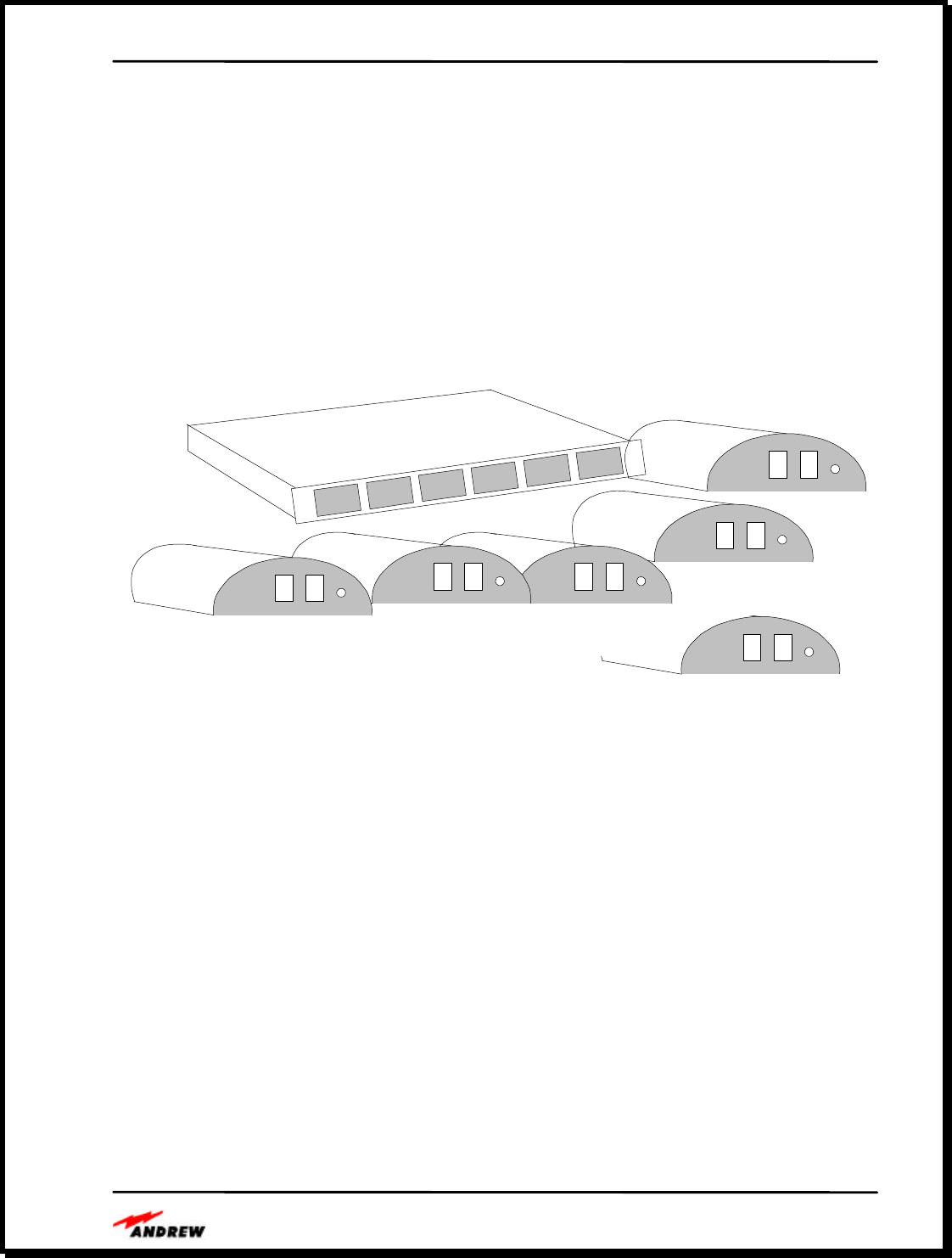
InCell™ Fiber Optic Distributed Antenna System Description
The subsystem consists of one or more Central Distribution Units (CDU) feeding multiple
Remote Antenna Units (RAU).
Figure 1. InCell™
This unit can drive up to 6 RAU’s. Additional CDU’s can be driven using one or more of
our Signal Distribution Units (SDU). The required signal distribution is built into the back-
plane of the chassis minimizing the need for interconnecting cables. Our design is
intrinsically optimized for new technologies operating at higher bandwidths.
Unlike other competing products, this product is designed for multi-operator, multi-service
capabilities with higher output levels and lower system sensitivities. This equates to greater
coverage range per antenna unit and hence lower implementation costs. When complete,
this product will be available in both single-band units, i.e., US Cellular, GSM 900, US
PCS-1900, and DCS-1800, and dual band units in which both low and high band services
are supported within the same unit using the same fiber pair.
Figure 2. InCell™ Form Factors
Andrew InCell™ Fiber Optic Distributed Antenna System Users Guide
- 2 -
RAU Front
View
CDU Side View
RAU Front
View
RAU Front
View
RAU Front
View
RAU Front
View
RAU Front
View

Andrew InCell™ Fiber Optic Distributed Antenna System Users Guide
- 1 -
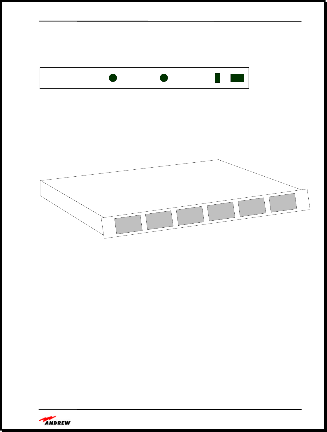
Central Distribution Unit (CDU)
The Central Distribution Unit (CDU) is the core module that can drive up to six Remote
Antenna Units (RAU. The CDU separates the down and uplink RF signals and converts
these to optics for transmission over a 2-core single-mode fiber cable to one of six RAU’s.
The CDU (shown at Figure 3) is housed in a standard 1U, 19-inch rack mount unit and
provides 6 sets of duplex optical fiber links to the remote antenna units.
Figure 3. InCell™ Central Distribution Unit
The figure below provides a detailed view of the CDU front panel, showing the six remote
antenna interface ports. Each of the six ports is identical and provides DC power for the
remote antenna as well as a downlink interface and an uplink interface with the remote
antenna unit.
CDU FRONT PANEL
Andrew InCell™ Fiber Optic Distributed Antenna System Users Guide
- 2 -
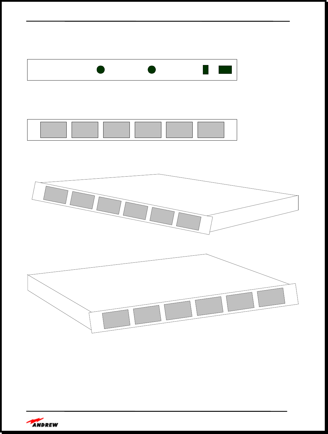
The rear view of the CDU shows the RF input/output connector as well as the power
connection and the on/off switch. The RF connections are Type N.
CDU REAR PANEL
CDU Side View
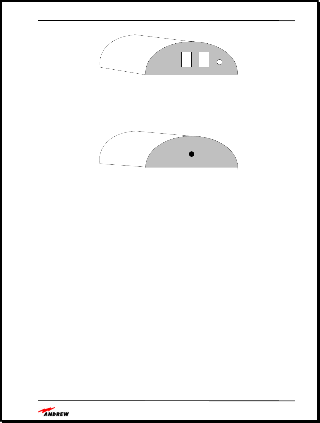
Remote Antenna Unit (RAU)
The RAU converts the signal back to RF and provides a single duplex downlink and uplink
output port; and the dual band unit combines the two services to a single RF connector. The
third order intercept point is high (33dBm typical), and the output can go directly to a multi-
band antenna or be split to drive multiple antennas.
Andrew InCell™ Fiber Optic Distributed Antenna System Users Guide
- 3 -
RAU Front View
RAU Rear View
CDU Status Indicators
RAU Status Indicators
Alarm Output
Remote Monitoring Option

Andrew InCell™ Fiber Optic Distributed Antenna System Users Guide
- 4 -
CDU to RAU Interface Cables
Composite Fiber Optic & Power Cables
Standard Duplex Fiber Optic Cables
Andrew InCell™ Fiber Optic Distributed Antenna System Users Guide
- 5 -
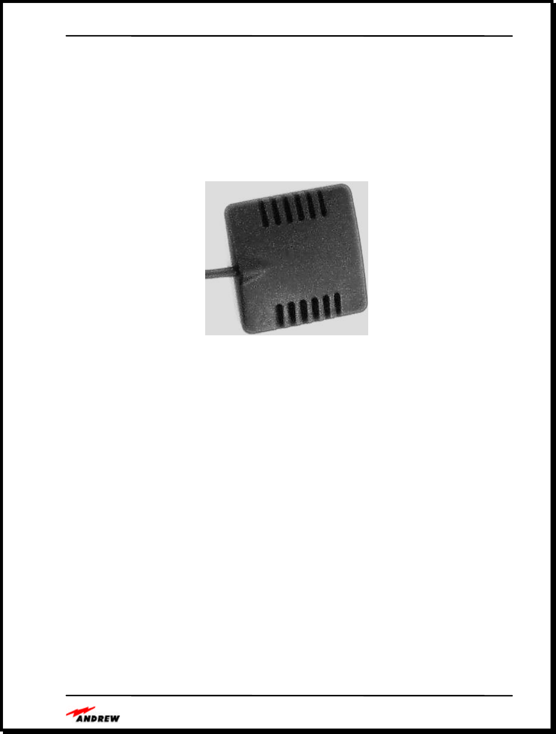
Indoor Antennas
Andrew is developing several new low profile in-building antennas like the examples in
Figure 4 and Figure 5. These dual band antennas are based on a product originally designed
by our automotive accessory division. We anticipate releasing other antenna products in the
next calendar year.
Figure 4. Andrew Dual Band
Patch Antenna
Figure 5. Andrew Dual Band Omni Antenna

Andrew InCell™ Fiber Optic Distributed Antenna System Users Guide
- 6 -
Outdoor Donor Antennas
Lightning Arrestors
Bi-Directional Amplifiers
Coaxial Cables and Jumpers
Distributed Antenna System Planning
InCell Distributed Antenna System Bill of Material
Andrew InCell™ Fiber Optic Distributed Antenna System Users Guide
- 7 -
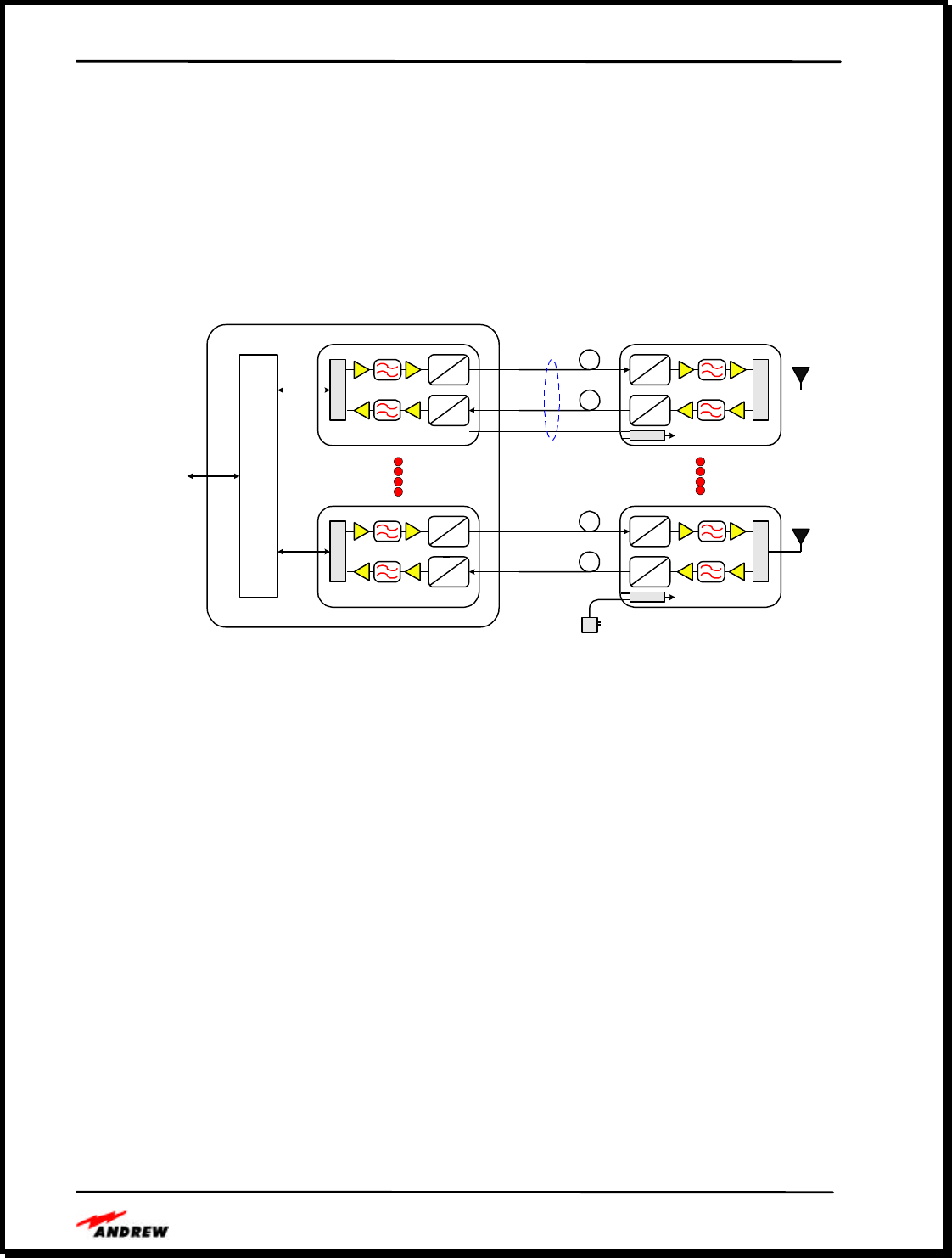
In-Building Implementations Using the Andrew InCell™ System
Scalable System Architecture
The InCell™ distributed antenna system is a scalable system that can be configured to support up
to 384 antenna locations using three building block modules.
OE
Fiber Optic Receiver
Fiber Optic Transmitter
D
U
P
L
E
X
E
R
Power
Fiber Optic Receiver
Fiber Optic Transmitter
D
U
P
L
E
X
E
R
Power
Remote Antenna Unit #1
Remote Antenna Unit #6
E
O
OE
OE
Composite Fiber/Copper
Cable
18 AWG Copper Wire
Fiber Optic Receiver
Fiber Optic Transmitter
O
E
O
E
Fiber Optic Receiver
Fiber Optic Transmitter
O
E
O
E
Single Mode Fiber -- Downlink
Single Mode Fiber -- Uplink
Single Mode Fiber -- Downlink
Single Mode Fiber -- Uplink
Local Power Supply
(Wall Transformer)
RF, Test Signal & Power
Distribution
6-Channel Central Distribution Unit
Figure 6. Simplified InCell™ Block Diagram

Andrew InCell™ Fiber Optic Distributed Antenna System Users Guide
- 8 -
The RAU is (shown at Figure 7) weighs only 0.6 pounds and is 38 mm (length) x 127 mm
(width) x 165 mm (height). This compact size makes it suitable for close mounting to the
antenna.
Figure 7. Remote Antenna Unit
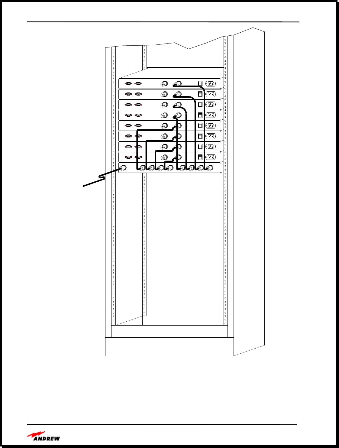
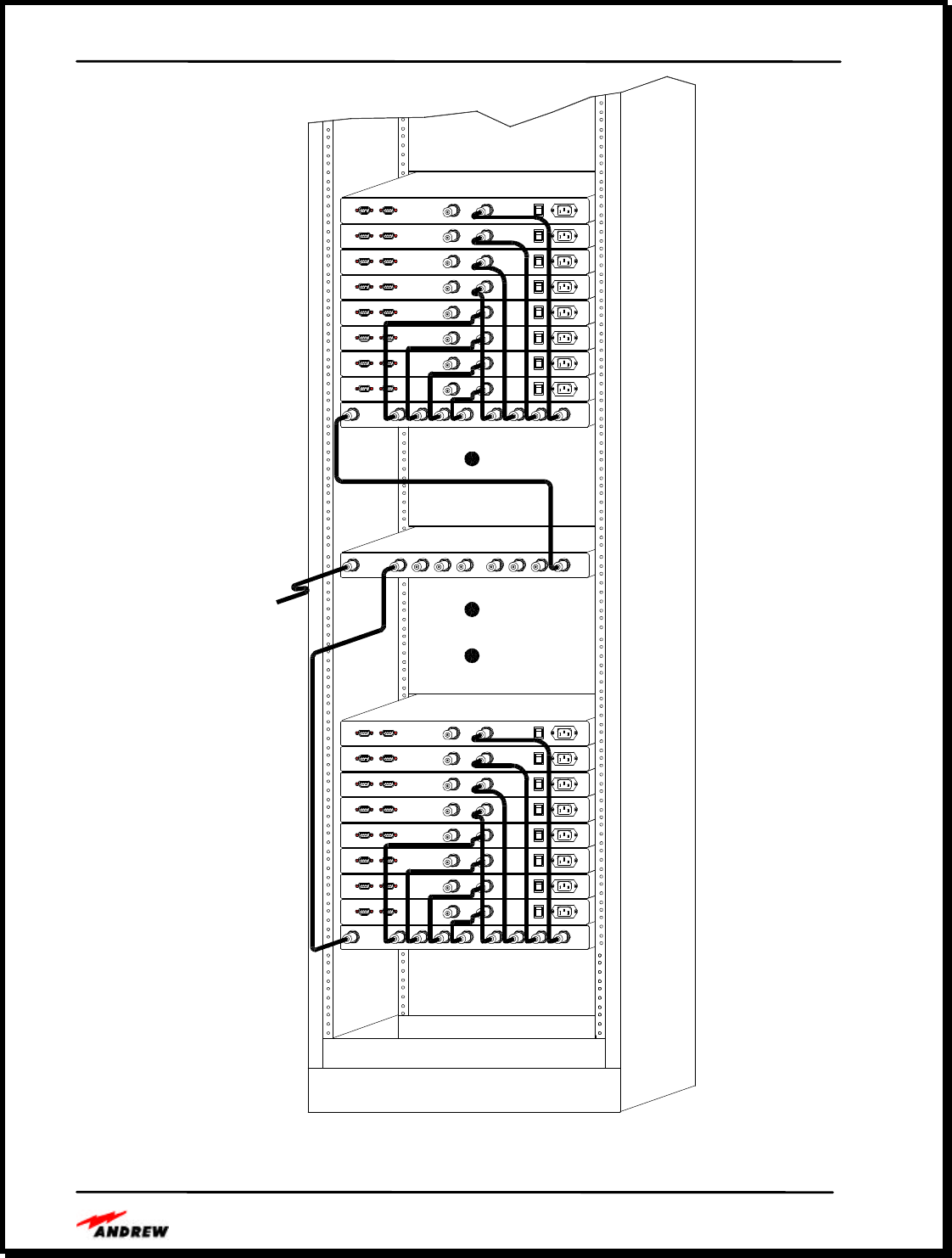
The Signal Distribution Unit
The third building block module is the Signal Distribution Unit (SDU). This is a 1U rack mount
unit housing a standard 8-way power divider that is placed in front of the CDU to drive eight
CDU’s from one service input. Using an architecture of one SDU and eight CDU’s, 48 antenna
locations can be served (see Figure 8). Using an architecture of nine SDU’s dividing the service
signal to 64 CDU’s, 384 antenna locations can be served (see Figure 9). These approaches are
best housed coherently in 19-inch equipment racks as depicted in Figures 25 and 26.
Andrew InCell™ Fiber Optic Distributed Antenna System Users Guide
- 9 -
REMOTE ALARM RF 100-240 VACRF POWER
REMOTE ALARM RF RF 100-240 VACPOWER
REMOTE ALARM RF RF 100-240 VACPOWER
REMOTE ALARM RF RF 100-240 VACPOWER
REMOTE ALARM RF RF 100-240 VACPOWER
REMOTE ALARM RF RF 100-240 VACPOWER
REMOTE ALARM RF RF 100-240 VACPOWER
REMOTE ALARM RF RF 100-240 VACPOWER
RF RF RF RF RF RF RF RFRF
REMOTE ALARM
REMOTE ALARM
REMOTE ALARM
REMOTE ALARM
REMOTE ALARM
REMOTE ALARM
REMOTE ALARM
REMOTE ALARM
D00-45
RF IN
Figure 8. System expandability to 48 RAUs
Andrew InCell™ Fiber Optic Distributed Antenna System Users Guide
- 10 -
REMOTE ALARM RF 100-240 VACRF POWER
REMOTE ALARM RF RF 100-240 VACPOWER
REMOTE ALARM RF RF 100-240 VACPOWER
REMOTE ALARM RF RF 100-240 VACPOWER
REMOTE ALARM RF RF 100-240 VACPOWER
REMOTE ALARM RF RF 100-240 VACPOWER
REMOTE ALARM RF RF 100-240 VACPOWER
REMOTE ALARM RF RF 100-240 VACPOWER
RF RF RF RF RF RF RF RFRF
REMOTE ALARM
REMOTE ALARM
REMOTE ALARM
REMOTE ALARM
REMOTE ALARM
REMOTE ALARM
REMOTE ALARM
REMOTE ALARM
D00-46
RF
REMOTE ALARMREMOTE ALARM
RF RF
REMOTE ALARM
REMOTE ALARMREMOTE ALARM
REMOTE ALARM
REMOTE ALARM
REMOTE ALARMREMOTE ALARM
REMOTE ALARM
REMOTE ALARM
REMOTE ALARMREMOTE ALARM
REMOTE ALARM
REMOTE ALARMREMOTE ALARM
RF RF
RF
RF
RF
RF RF
POWER
RF
100-240 VAC
RF
RF
RF
RF
RF
RF
RF
RF
POWER
POWER
100-240 VAC
100-240 VAC
POWER
POWER
100-240 VAC
100-240 VAC
RF
RF
RF
RF
RF RF
POWER
POWER
100-240 VAC
100-240 VAC
POWER 100-240 VAC
RF RFRF RFRFRF RFRFRF
RF IN
Figure 9. System Expandability to more than 48 RAUs
Andrew InCell™ Fiber Optic Distributed Antenna System Users Guide
- 11 -
The Interconnecting Cable
Any single mode 2-core fiber cable can be used to drive the RAU a distance of 20Km from the
CDU. In this configuration, power to the RAU is supplied from an external 12-28VDC source or
an Andrew supplied universal (110/240VAC, 50/60Hz) wall transformer (wall wart). An
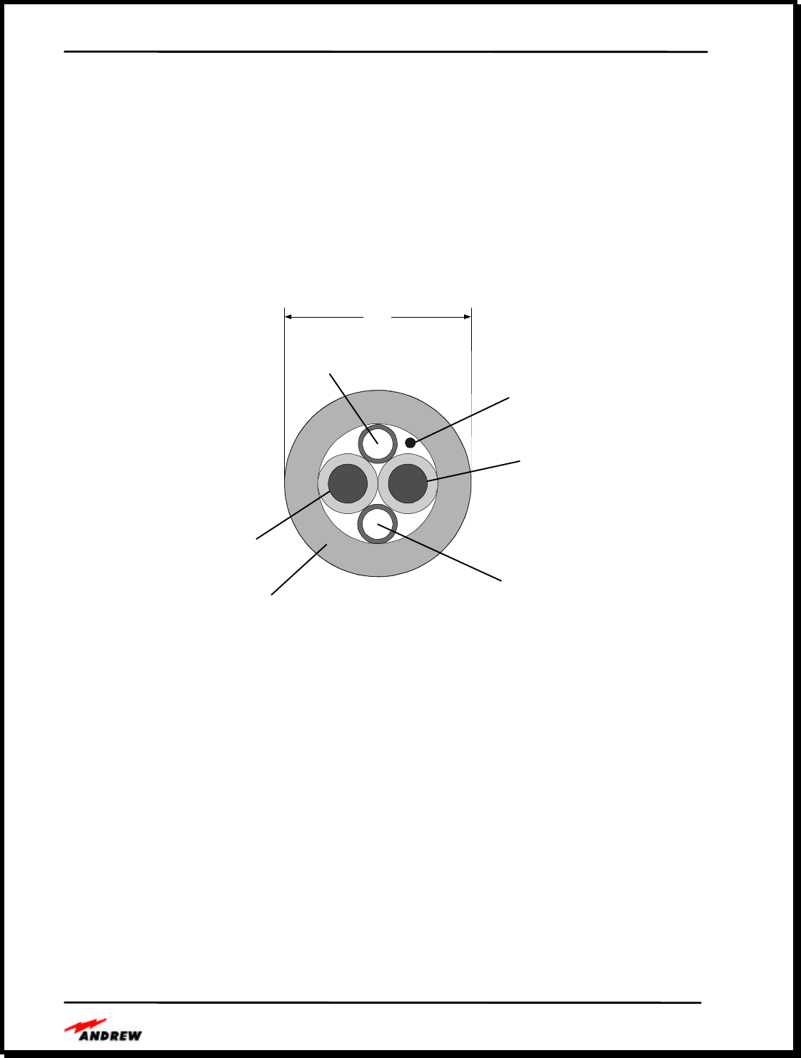
Andrew manufactured composite cable is also available. This cable (shown at Figure 10)
combines 2-core fiber and 2-conductor copper elements in a single jacket. Using this cable,
power to the RAU is supplied by the CDU over the copper conductors eliminating the need for a
separate RAU power supply. Although the composite cable greatly simplifies the installation
process, the CDU-RAU separation is limited to 1.5Km. The limitation is the DC voltage drop
from the CDU to the RAU over the copper conductors.
Microcable
Natural
Insulated
Copper
(Red)
Rip Cord
Outer
Jacket
Insulated
Copper
(Black)
Microcable
(Blue)
0.210"
TM
TM
D00-37
Figure 10. Cross Section of Andrew Composite Fiber/Copper Cable
The Andrew composite cable is rugged, flexible and has an outside diameter of 0.21”, making it
easy to install. One optical fiber provides the downlink signal between the CDU and the RAU;
the second optical fiber provides the uplink signal between the RAU and the CDU. These cables
use industry standard SC type connectors to interface with the RAU and CDU. The two copper
lines are used to provide DC power and ground signals to the RAU so that no additional power
planning is required. System installers are not required to install AC power, conduit and
transformers at each remote antenna location. With the CDU in the center of a system, remote
antennas could be spaced as far as 3 km apart using the composite cable.
Andrew provides plenum rated and riser rated composite cables for in-building installation as
fully tested cable assemblies and as bulk cable. The cables meet demanding building codes for
safety. Tested cable assemblies are available in lengths of 50, 100, 150 and 200 meters, with
optical and power connectors installed. Bulk composite cable is also available on spools and
Andrew InCell™ Fiber Optic Distributed Antenna System Users Guide
- 12 -
requires system installers to add crimp-on connectors for the copper lines and add SC type
connectors to the fiber cables. Refer to Andrew Catalog 38, pages 642-645, for full
specifications of the plenum and riser rated cables. Andrew cable assemblies also come with a
pulling hook and harness to make the cables easier to install.
If the in-building location for each of the remote antenna units is pre-planned and the distances
are all known, then composite cables with connectorized ends and installation-ready wraps can
be ordered to specific lengths. The other option is to buy reels of composite cable and then
connectorize them in field. The connectors for the copper wires are fairly easy to crimp on, but
the SC-connectors take a few minutes and require the use of a non-fusion based splicing device
and well trained technicians to insure that reliable, low loss splices are made.
Single mode fiber optic cable is used in the InCell™ products because of its wide bandwidth and
loss attenuation characteristics. Single mode fiber optic cable has the lowest attenuation of all
fiber optic cable types and is typically lower in cost than multimode fiber cable. Single mode
fiber is used in communications systems where high data rates and wide bandwidths are
required. Wideband fiber optic line provides for unlimited future growth. Typical single mode
cable loss is 0.4 dB per km. The loss of two SC connectors is typically 0.5 dB.
The SC type connector is the most popular connector type for the fiber-optic cables. The SC
connector is the recommended connector in the EIA/TIA-568A building wiring standard. It
provides a very reliable, low loss connection at a reasonable cost. The SC type connector is easy
to install and provides positive feedback when correctly seated. SC connectors have good lock,
pull and wiggle characteristics, ensuring that they will stay in place when installed and that they
are immune to tension or lateral pressure on the fiber cable.
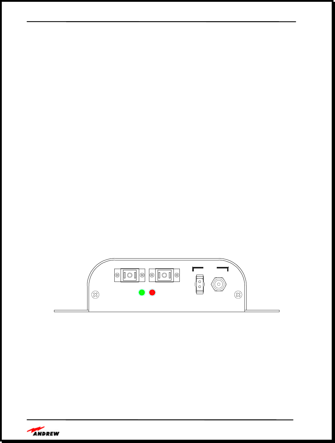
Figure 11 shows the RAU fiber and power connections.
POWER
U/L D/L PWR
D00-44
Rem Loc
Figure 11. Remote and Local Power Connections on the RAU

Andrew InCell™ Fiber Optic Distributed Antenna System Users Guide
- 13 -
The Installation Parameters
Installation times will depend on the size of each installation; however, Andrew can provide
rough guidelines for installing the CDU and RAU that may be used to determine the total system
installation time once the number of equipment parts is determined.
The CDU may be mounted in a standard 19” equipment rack or on a wall. Allow 30 minutes for
unpacking the CDU, installing the unit into the rack or wall and connecting the RF, fiber and
power cables. Upon application of system power, front panel indicators will give the installer a
visual indication of power and link status. Mounting hardware is provided for rack or wall
mounting.
RAUs are typically mounted on walls or ceilings throughout the building. The units are small
and lightweight and installers may carry multiple RAUs at one time to speed installation.
Mounting the RAU to a wall or ceiling and connecting the fiber and power cables and the
antenna takes only minutes. Upon application of system power, indicators on the RAU give the
installer a visual indication of RAU power and link status. Mounting hardware is provided for
the RAU.
To minimize system wiring times, Andrew composite cable is recommended to allow the fiber
optic links and the power to be routed to each RAU in one small, easy to pull cable. The
composite cables eliminate the need for conduit to each remote antenna location, improving
wiring installation time.
Disruption to business is minimal as the CDU is typically installed in a electronic equipment
room and the remote antennas and wiring may be installed after work hours. The cables are
small and lightweight making them easy to pull through risers, above roofs and through tubes.
Site survey testing before and after installation may be done during business hours using small,
portable RF measurement tools.
Andrew InCell™ Fiber Optic Distributed Antenna System Users Guide
- 14 -
CDU REAR PANEL
CDU FRONT PANEL
CDU Side View
CDU Side View
Andrew InCell™ Fiber Optic Distributed Antenna System Users Guide
- 15 -
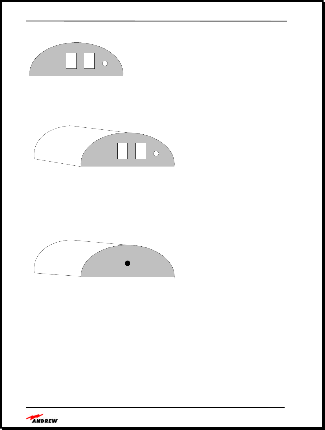
RAU Front View
RAU Front View
RAU Rear View
Andrew InCell™ Fiber Optic Distributed Antenna System Users Guide
- 16 -
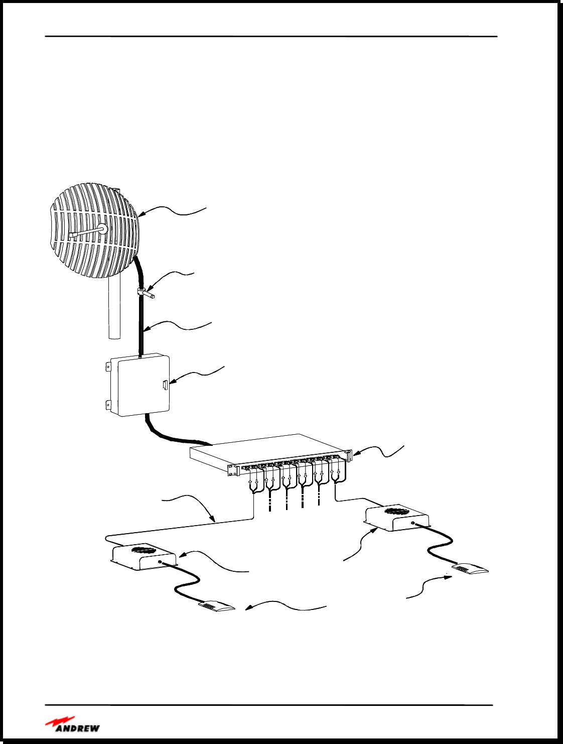
Sample Implementation
Figure 12 illustrates a small off-air implementation using an Andrew GridPACK donor antenna,
an Andrew Cellular Extender (ACE), and a single InCell™ Central Distribution Unit driving up
to six Remote Antenna Units. The donor antenna and extender can be replaced with other RF
inputs, such as another off-air interface, a base station, or distribution unit depending on the
application.
Andrew
IInCell
Remote Antenna Unit
Andrew
Composite
Optical Fiber Cable
(up to 1.5 Km)
Andrew
InCell
Central Distribution Unit
Andrew
Off-Air
Repeater Family
Andrew
Surge Arrester
Andrew
GRIDPACK
High Gain Donor Antenna
Andrew
Heliax Cable
Indoor
Patch Antenna
Andrew
IInCell
Remote Antenna Unit
Andrew
Composite
Optical Fiber Cable
(up to 1.5 Km)
Andrew
InCell
Central Distribution Unit
Andrew
Off-Air
Repeater Family
Andrew
Surge Arrester
Andrew
GRIDPACK
High Gain Donor Antenna
Andrew
IInCell
Remote Antenna Unit
Andrew
Composite
Optical Fiber Cable
(up to 1.5 Km)
Andrew
InCell
Central Distribution Unit
Andrew
Off-Air
Repeater Family
Andrew
Surge Arrester
Andrew
GRIDPACK
High Gain Donor Antenna
Andrew
Heliax Cable
Indoor
Patch Antenna
Andrew
Heliax Cable
Indoor
Patch Antenna
Figure 12. Typical System Configuration Using Off-Air Interface
Andrew InCell™ Fiber Optic Distributed Antenna System Users Guide
- 17 -
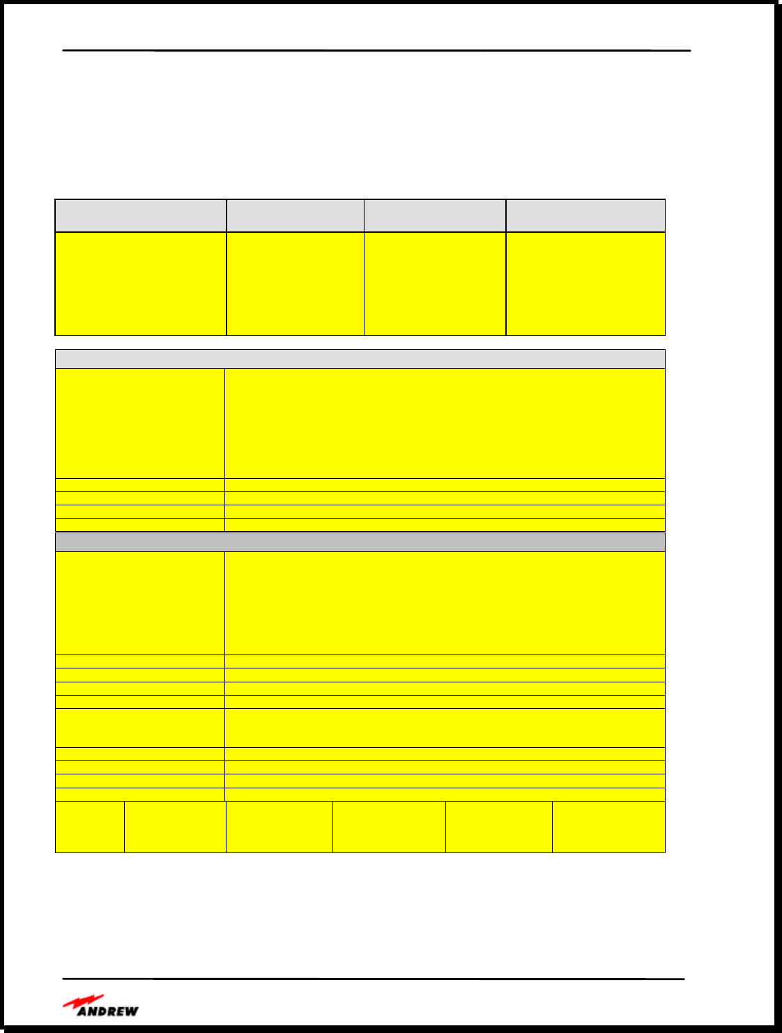
InCell™ Specifications
Technical Performance
The technical specifications are summarized in Table 1.
Table 1. InCell™ Performance Specification
Wireless Service Standard InCell Part Number Downlink Passband
(MHz)
Uplink Passband
(MHz)
US Cellular
(AMPS/TDMA/CDMA)
GSM-900
DCS-1800
PCS-1900
2.4 GHz ISM WLAN
US Cellular/PCS-1900
GSM-900/GSM-1800
2000-1000-000
2000-2000-000
2000-3000-000
2000-4000-000
2000-5000-000
2000-6000-000
2000-7000-000
869-894
935-960
1805-1880
1930-1990
2400-2500
869-894/1930-1990
935-960/1805-1880
824-849
890-915
1710-1785
1850-1910
2400-2500
824-849/1850-1910
890-915/1710-1785
InCell™ Downlink Performance
InCell™ Uplink Performance
Uplink Frequency Range
2000-1000-000 (US Cellular)
2000-2000-000 (GSM-900)
2000-3000-000 (DCS-1800)
2000-4000-000 (PCS)
2000-5000-000 (WLAN)
2000-6000-000 (Dual Band)
2000-7000-000 (Dual Band)
824-849 MHz
890-915 MHz
1710-1785 MHz
1850-1910 MHz
2400-2500 MHz
824-849/1850-1910 MHz
890-915/1710-1785 MHz
End-to-End RF Gain (dB) 15 dB
Gain Flatness Over Frequency +/- 2.5 dB
Maximum Input Power Limiter threshold at -40 dBm
Noise Figure* 11 dB
Downlink Freqnency Range
2000-1000-000 (US Cellular)
2000-2000-000 (GSM 900)
2000-3000-000 (DCS-1800)
2000-4000-00 (PCS)
2000-5000-000 (WLAN)
2000-6000-000 (Dual Band)
2000-7000-000 (Dual Band)
869-894 MHz
935-960 MHz
1805-1880 MHz
1930-1990 MHz
2400-2500 MHz
869-894/1930-1990 MHz
935-960/1805-1880 MHz
End-to-End RF Gain (dB) 15 dB
Gain Flatness Over Frequency +/-2.5 dB
Maximum Input Power 20 dBm
Return Loss >17 dB
Spurious/Intermodulation -13 dBm for non-European Systems
-36 dBm from 9 kHz to 1 GHz
-30 dBm from 1 GHz to 12.75 GHz
1 dB Compression Point 20 dBm
Output Intercept Point 20 dBm
Wideband Noise -121.5 dBm/Hz
CDMA Spectral Regrowth -45 dBc
Output
Power
Analog
15 dBm, 2 carriers
12 dBm, 4 carriers
9 dBm, 8 carriers
TDMA
15 dBm, 2 carriers
12 dBm, 4 carriers
9 dBm, 8 carriers
CDMA
10 dBm, 1 carrier
4 dBm, 2 carriers
GSM-900
10 dBm, 2 carriers
7 dBm, 4 carriers
4 dBm, 8 carriers
DCS-1800
12 dBm, 2 carriers
9 dBm, 4 carriers
6 dBm, 8 carriers
Andrew InCell™ Fiber Optic Distributed Antenna System Users Guide
- 18 -
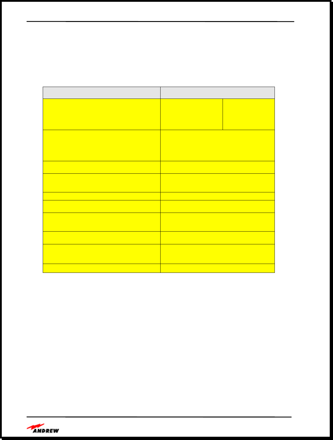
Interface Specifications
The BTS interface specifications are shown in Table 2 and the antenna interface specifications
are in Table 3.
Table 2. BTS Interface Specifications
Requirement Performance Specification
Operational Bandwidth GSM-900
DCS-1800
Dual Band 900/1800
Uplink
890-915 MHz
1710-1785 MHz
890-915 MHz
1710-1785 MHz
Downlink
935-960 MHz
1805-1880 MHz
935-960 MHz
1805-1880 MHz
Connector Types- CDU RF
Optical Fiber
AC Power (CDU only)
DC Power
Type N
Type SC Single Mode Fiber
Standard 3-pin “D” type
Molex 2-pin
Connector Locations RF and AC connectors on rear of CDU
Fiber and DC power on front of CDU
Interface Type
RF
Optical Fiber Duplex (bi-directional port)
Single mode fiber: 1 uplink, 1 downlink
RF Impedance/VSWR 50 ohms, typical 10 dB return loss
1 dB Compression Point
Downlink 20 dBm
Third Order Output Intercept Point
Downlink
Uplink
N/A
Spurious Response -36 dBm from 9 kHz to 1 GHz
-30 dBm from 1 GHz to 12.75 GHz
Gain/Gain Linearity
Downlink
Uplink 15 db ± 2.5
15 db ± 2.5
Group Delay <1.0 usec (CDU, fiber and RAU)
Andrew InCell™ Fiber Optic Distributed Antenna System Users Guide
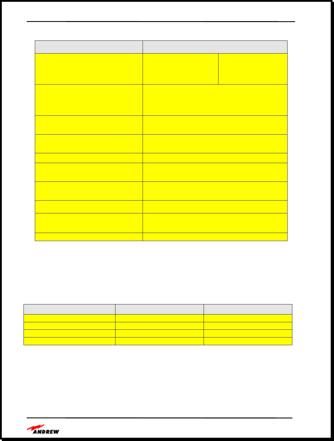
- 19 -
Table 3. Antenna Interface Specifications
Requirement Performance Specification
Operational Bandwidth GSM-900
DCS-1800
Dual Band 900/1800
Uplink
890-915 MHz
1710-1785 MHz
890-915 MHz
1710-1785 MHz
Downlink
935-960 MHz
1805-1880 MHz
935-960 MHz
1805-1880 MHz
Connector Types- RAU RF
Optical Fiber
AC Power (CDU only)
DC Power
SMA
Type SC Single Mode Fiber
N/A
Molex 2-pin
Connector Locations RF connector on rear of RAU
Fiber and DC power on front of RAU
Interface Type
RF
Optical Fiber Duplex (bi-directional port)
Single mode fiber: 1 uplink, 1 downlink
RF Impedance/VSWR 50 ohms, typical 10 dB return loss
1 dB Compression Point
Downlink
Uplink 20 dBm
N/A
Third Order Output Intercept Point
Downlink
Uplink 36 dBm
-6 dBm
Spurious Response -36 dBm from 9 kHz to 1 GHz
-30 dBm from 1 GHz to 12.75 GHz
Gain/Gain Linearity
Downlink
Uplink 15 db ± 2.5
15 db ± 2.5
Group Delay <1.0 usec (CDU, fiber and RAU)
Electrical Specifications
The power requirements for the first and second generation Central Distribution Units (CDU) are
summarized in Table 4. The RAU is generally remotely powered from the CDU.
Table 4. Electrical Specifications
Slim Line Smart Rack 3U
Line Voltage 100 – 240 VAC, 47 – 63 Hz 100 – 240 VAC, 47 – 63 Hz
Power Consumption 40 Watts (CDU w/6 RAU’s) 140 Watts (CDU w/20 RAU’s)
Power Supply Redundancy None Hot Standby
Backup Power Supply External External

Andrew InCell™ Fiber Optic Distributed Antenna System Users Guide
- 20 -
Environmental and Mechanical Specifications
The environmental and mechanical specifications are summarized in Table 5. We have not
completed shock and vibration testing at this time.
Table 5. InCell™ Environmental and Mechanical Specification
Parameters CDU RAU
Enclosure Dimensions 1.75”H x 16.75”W x 12”D
1U, 19” rack-mountable 1.5”H x 5”W x 6.5”D
Enclosure Weight 4 pounds 0.6 pounds
RF Connector N-female, bi-directional SMA-female, bi-directional
Fiber Connector 6 pairs (12), SC Type 1 pair (2), SC Type
Remote Alarm from CDU 9-pin D-Sub with summary power and
system link status N/A
Local Alarm One power and one link status LED per
antenna port One power and one link status LED
AC Power 100-240 VAC, 47-63 Hz N/A
DC Power 24 VDC output to each RAU +28 to +12 VDC input
Maximum DC Power Draw CDU: 10 Watts
System: 40 Watts with 6 RAUs 5 Watts
MTBF > 27,000 hours > 180,000 hours
Storage Temperature -10 to +70o C
Operating Temperature 0 to +50o C
Humidity 0 to 95 % RH, non-condensing
MTBF
A system MTBF using one CDU and six RAU’s is calculated to be 26,954 hours for the slim line
unit and 9,851 hours for a fully populated 3U 20 unit chassis. Each RAU has a MTBF of
181,265 hours. These MTBF values were calculated using the Bellcore part count method.
MTTR
Low MTTR values are achieved due to the extensive internally monitoring capability. The
MTTR of the Slim Line unit is estimated at 15 minutes using a board replacement maintenance
concept. The MTTR for the 3U chassis is less than 5 minutes as modules can be easily replaced
while the unit is operating. The RAU MTTR is 5 to 30 minutes depending upon the complexity
and ease of access to the installed device. The proposed maintenance concept for the RAU is a
direct replacement of the unit.

Andrew InCell™ Fiber Optic Distributed Antenna System Users Guide
- 21 -
InCell™ Network Monitoring System
The InCell™ family is designed to minimize maintenance and monitoring costs. Provisions are
made for both local and remote monitoring of small and large systems. The InCell™ system
continuously monitors and reports status of the system hardware, by a combination of indicators
available at the central hub and at each remote antenna and alarms for remote monitoring that aid
in system fault detection and fault isolation down to a circuit board or cable.
The wideband, single mode fiber cable allows a low frequency RF test signal to be continuously
passed over the downlink and uplink signal paths with multiple RF wireless signals. In a dual
band system, the 67 MHz pilot test signal, the 800 MHz service, and the 1900 MHz service
signals simultaneously pass through the downlink and uplink paths.
Pilot Tone Generation
The CDU generates a continuous pilot tone for system level fault detection and isolation and
distributes the signal to each RAU port. This low frequency RF tone is combined with the
downlink RF signal and transmitted over the fiber optic cable to the RAU where it is received
and filtered from the downlink RF signal. In the RAU, the pilot tone is filtered, amplified and
combined with the RF uplink signal to be sent over the optical uplink path back to the CDU.
Within the RAU, the pilot tone is detected by a threshold detector to indicate the presence of the
pilot tone at a minimum signal level. The pilot threshold detector drives an LED on the RAU
that indicates that the downlink optical signal path to the RAU is connected.
The return path pilot tone from the RAU is also filtered, amplified and detected. The detected
pilot signal is passed to a threshold detector to indicate the tone presence at a minimum signal
level. The pilot threshold detector in turn drives an LED at each port of the CDU indicating that
both the downlink to the RAU and the uplink back to the CDU are connected and that power is
properly functioning at the RAU.
RAU Indicators
The Power indicator on the RAU shows that DC power from the composite cable is present at
the RAU. If the indicator is green, DC power is present in the RAU.
The LINK indicator on the RAU shows that the pilot tone from the CDU is present over the
downlink. When the LINK indicator is off on the RAU, the downlink optical path between the
CDU and the RAU is installed correctly and DC power is present in the RAU. If the LINK
indicator is red, there may be a problem with the downlink optical path between the CDU and
RAU or a problem with the RAU power. The RAU indicators allow system installers and
maintainers to easily determine the RAU functional status, the power supply status, and the
downlink optical path status.
CDU Front Panel Indicators
The Power indicator for each port of the CDU indicates that the DC power is present at that port.
If the CDU Power indicator is green, power is good at that CDU port, also indicating that the
internal AC power supply is good. If the Power indicator for one CDU port is off, there is

Andrew InCell™ Fiber Optic Distributed Antenna System Users Guide
- 22 -
problem with that CDU port interface. If the Power indicators for all CDU ports are off, the AC
power supply may be bad, AC power may be switched off or there may be another problem with
the AC power.
The LINK indicator at each CDU port shows that the CDU generated pilot tone was sent over
the downlink from the CDU to the RAU then received and transmitted over the uplink path from
the RAU back to the CDU. When the CDU LINK indicator is off, the downlink and uplink
optical paths are installed correctly and DC power is present in the RAU. If the LINK indicator
is red, there may be a problem with the fiber optic signals between the CDU and RAU; a
problem with the RAU power; or a problem with the RAU itself. The CDU indicators allow
system installers and maintainers to easily determine each RAU functional status, power
distribution to each RAU, and the correct connection of the fiber optic cables.
Alarm Functions
The CDU has two alarm outputs on the rear panel to indicate the overall health of the power
supply and the uplink and downlink to each remote antenna units. The link alarm output is a
summary alarm of all of system uplinks and downlinks and remote antenna power. The alarm
outputs are through a DB-9 connector located on the CDU chassis rear panel.
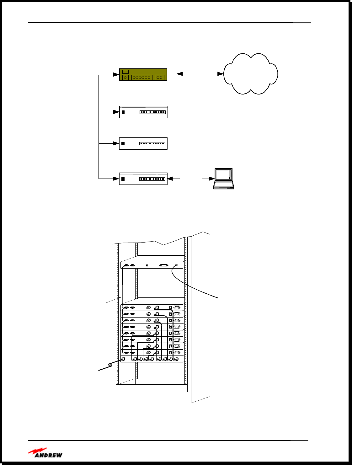
Remote Monitoring Functions
As an option that will be available in February 2001, InCell™ Systems will support remote
system health monitoring using standard protocols that will allow customers to monitor full
system status. This feature uses an embedded processor (see Error! Reference source not
found.) to monitor and report system health for the CDU and all RAUs, including power
supplies, uplink and downlink paths and cables.
With this option, the InCell™ System hardware can be remotely monitored in three ways:
v Locally using a RS-232 connection to a terminal or PC (see Figure 13)
v Remotely using an SNMP Agent chassis connected to a telephone, LAN/WAN or other
communications medium
v Remotely using dry-contact terminals connected to a third party SCADA
In the first method, the RS-232C interface option does not require a separate chassis. An RS-485
bus daisy chains the system status and alarms together as illustrated in Figure 13 and Figure 14.
Communications between CDU’s is accomplished over an RS-485 link, and the user can connect
to the master bus using a standard computer or RS-232C terminal.
In the second method, a separate 1U chassis is required to act as the SNMP agent. The SNMP
agent allows a network management system to monitor InCell™ device(s) by telephone or
network connection using industry standard interfaces. The SNMP agent performs network
management operations such as setting configuration parameters, alarm notification and current
operation statistics. A database of the InCell™ network management information, called the
management information base (MIB), is maintained by the Agent.
Andrew InCell™ Fiber Optic Distributed Antenna System Users Guide
- 23 -
In the third method, dry contact alarm terminals can be connected to a third party SCADA
system over copper wires.
Laptop computer
InCell
InCell
InCell
RS-232
(Local)
InCell Agent
SNMP Management
System
RS-485
(network)
Laptop computer
InCell
InCell
InCell
RS-232
(Local)
InCell Agent
SNMP Management
System
RS-485
(network)
Figure 13. Remote Alarm Capability
Figure 14. Daisy Chaining CDU’s for Remote Monitoring
REMOTE ALARM RF 100-240 VACRF POWER
REMOTE ALARM RF RF 100-240 VACPOWER
REMOTE ALARM RF RF 100-240 VACPOWER
REMOTE ALARM RF RF 100-240 VACPOWER
REMOTE ALARM RF RF 100-240 VACPOWER
REMOTE ALARM RF RF 100-240 VACPOWER
REMOTE ALARM RF RF 100-240 VACPOWER
REMOTE ALARM RF RF 100-240 VACPOWER
RF RF RF RF RF RF RF RFRF
REMOTE ALARM
REMOTE ALARM
REMOTE ALARM
REMOTE ALARM
REMOTE ALARM
REMOTE ALARM
REMOTE ALARM
REMOTE ALARM
D00-48
NETWORK
RF IN
INTERFACE
RS485
SERIAL

Andrew InCell™ Fiber Optic Distributed Antenna System Users Guide
- 24 -
InCell™ Operation, Maintenance and Support
Operation
InCell™ system operation is continuous. Andrew recommends using an uninterruptible power
supply (UPS) to provide power to the CDU. If the system uses composite cable to provide
power to the remote antenna units located throughout the building, the UPS can keep the CDU
and all RAUs powered and operational during brownouts and power outages.
Unlike some hybrid fiber distributed antenna systems that use frequency translation in the
wireless distribution process, the InCell™ uses no frequency synthesizers or synchronizing
circuitry that may be affected by power failures. The InCell™ operates immediately after power
is applied and is not susceptible to power failures.
Regular Maintenance
Minimal maintenance is required to support installed InCell™ systems. System maintainers
should ensure that all RF, power and fiber connectors are tight and that the CDU is mounted with
adequate room to allow air to flow into the chassis. Indicator LEDs show system status while
relay and optional remote alarm interfaces allow small or large system status to be monitored.
Andrew does recommend using a commercially available fiber optic cleaning kit to maintain
clean fiber optic connections. Typically, after system installation, no removal or cleaning of the
fiber connectors will be required.
Fault Repair
If a fault is detected in the system, maintainers can determine the problem cause problem by
reviewing reports from remote monitoring systems or by observing the front panel LED
indicators on the CDU chassis. Because the different CDU ports correspond to different remote
antenna locations, maintainers can determine where the problem exists in the building.
Maintainers can replace RAUs in the building without having to power down the system. If a
CDU fails, spare CDU boards can be installed.
Support
Andrew engineers and technicians familiar with the operation of the InCell™ system are
available Monday through Friday, 8am to 5pm CST. These personnel are familiar with
distributed in-building antenna systems, with fiber optic cable installation and with
troubleshooting and in-building coverage solutions.
In special cases, Andrew has provided local support of indoor wireless distributed antenna
systems. Please contact Andrew DCS if this type of maintenance support is required.
Spare Policy
For the Slim Line CDU assembly, we recommend sparing at the board level. This unit is
comprised of 2 unique board types and a power supply module. There is a single printed circuit
board that provides the necessary RF power, DC and alarm distribution and 6 identical printed

Andrew InCell™ Fiber Optic Distributed Antenna System Users Guide
- 25 -
circuit boards that perform the gain and optical conversion (see Error! Reference source not
found.). If the remote monitoring option is selected, there is a third 2-teir printed circuit board.