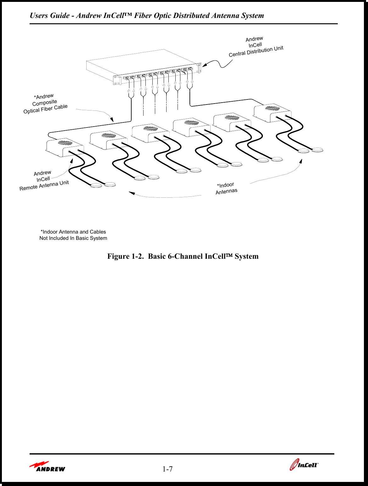
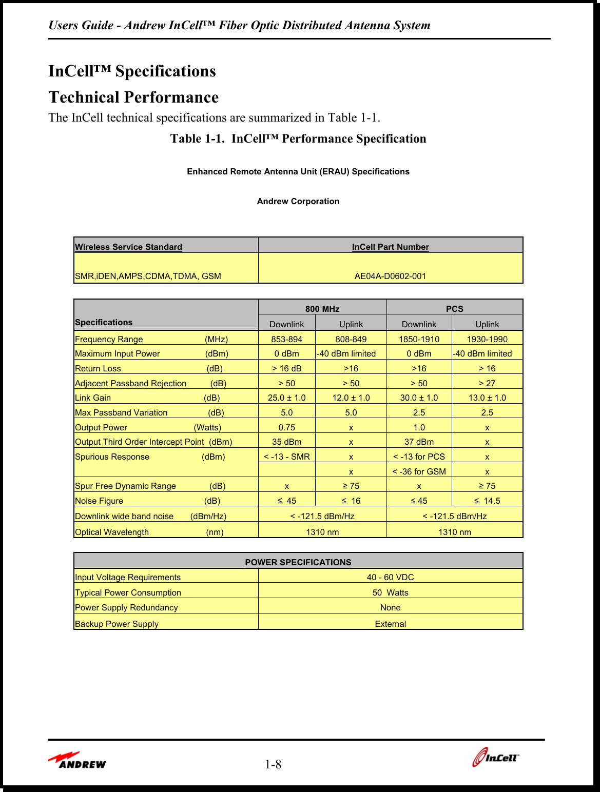
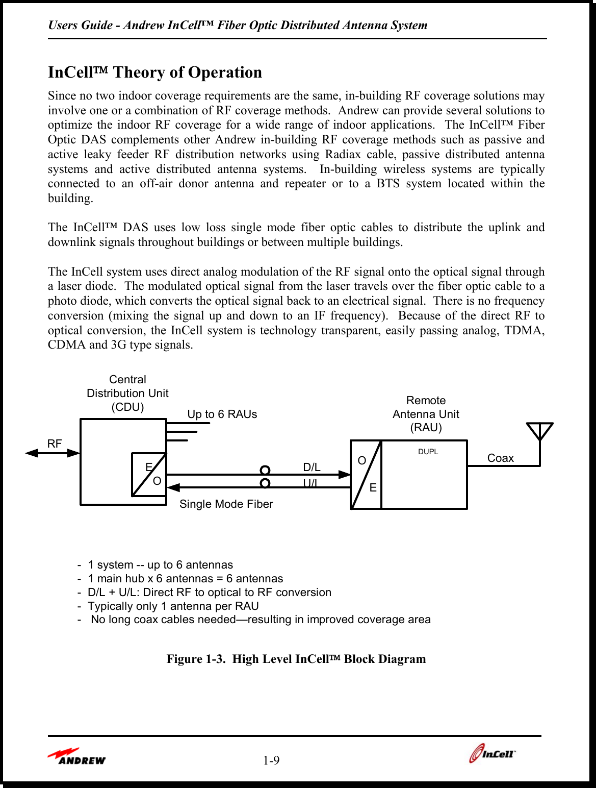
Andrew INCELLERAU1 Repeater User Manual Version 1 5 ERAU

Andrew Corporation Repeater Version 1 5 ERAU

Manual

               FFiibbeerr  OOppttiicc  DDiissttrriibbuutteedd  AAnntteennnnaa  SSyysstteemm     Installation and Users Guide            Copyright Andrew Corporation ERAU  Version 1.5 May 2002
Users Guide - Andrew InCell™ Fiber Optic Distributed Antenna System   - ii -   Proprietary Information This document is the property of Andrew Corporation.  The information contained herein is proprietary to Andrew, and no part of this document may be reproduced or transmitted in any form or by any means, electronic or mechanical, for any purpose, without the express written permission of Andrew.  Disclaimer Andrew reserves the right to make changes, without notice, to the specifications and materials contained herein.  While we have worked diligently to insure every element presented is correct, we shall not be responsible for errors.  For the latest product information and technical specifications, please see the contact information below.   Copyright Andrew Corporation, July 2001, Printed in USA, All rights reserved.  FCC Notice This equipment complies with Part 22 of the FCC rules.  Any changes or modifications not expressly approved by the manufacturer could void the user’s authority to operate the equipment.  Warning In order to comply with FCC rules for RF exposure, the following must be observed: 1.  The antenna for this device must have a gain of no more than 5.5 dBi. 2.  The antenna must be installed such that a minimum separation distance of 20 cm. is maintained between the antenna and any persons.  Trademarks InCell™ is a trademark of Andrew Corporation.  All other trademarks belong to their respective owner.  Contact Information For more information about Andrew’s capabilities to extend RF signals coverage into structures, including office buildings, shopping complexes, warehouses, tunnels, and mines, please contact us using the information below:    Andrew Corporation Distributed Communications Systems 2601 Telecom Parkway Richardson, Texas 75082  Attention: Mr. Matt Melester E-mail:matt.melester@andrew.com Fax: (972) 952-0018 Voice: (972) 952-9745
Users Guide - Andrew InCell™ Fiber Optic Distributed Antenna System    - iii -    Andrew Corporation Andrew Corporation is a global designer, manufacturer, and supplier of communications equipment, services, and systems.  Andrew products and expertise are found in communications systems throughout the world; including wireless and distributed communications, land mobile radio, cellular and personal communications, broadcast, radar, and navigation.  The Andrew "Flash" trademark seen on the cover can also be seen in every corner of the world on broadcast towers and microwave antennas, HELIAX® and RADIAX® cables, communications and computer networking equipment.  The mark of Andrew for more than 60 years, it is the benchmark of quality wherever it appears.  It is a symbol of commitment to customer satisfaction from the 4,500-plus employees of Andrew Corporation.  We are listed on the NASDAQ stock exchange under symbol “ANDW.” To learn more about us, please visit our web site at www.andrew.com.     Andrew In-Building Wireless Experience The Andrew Corporation Distributed Communications Systems (DCS) group has over 15 years experience designing, installing, and managing large complex RF distribution systems for metropolitan railways, building owners, and public mobile radio and telephone operators throughout the world.  For clients who do not need turnkey solutions, we offer product sales or product sales with engineering support services.    Andrew offers a range of products to meet requirements of the in-building market.  In the early 1980’s Andrew developed leaky cables as an adjunct to our coaxial cable business.  This product quickly led us to pursuing and executing wireless RF coverage in confined spaces such as metros, road tunnels, and buildings.  Through these projects, our Distributed Communications Systems division acquired critical experience in project management and RF engineering of these systems.
Users Guide - Andrew InCell™ Fiber Optic Distributed Antenna System    1-4      Section 1:    InCell Fiber Optic Distributed Antenna System Description  InCell Fiber Optic Distributed Antenna System Description   Page 1-5 InCell™ Specifications    Page 1-8 InCell Theory of Operation   Page 1-9 Downlink Signal Flow    Page 1-10 Uplink Signal Flow    Page 1-10
Users Guide - Andrew InCell™ Fiber Optic Distributed Antenna System    1-5    InCell Fiber Optic Distributed Antenna System Description The Andrew InCell™ Fiber Distributed Antenna System is designed to provide improved RF performance in buildings that suffer from poor wireless coverage.  The InCell™ interfaces directly with a BTS or off-air antenna and distributes RF signals to indoor antennas that provide improved downlink and uplink performance.  The InCell™ system uses multiple Enhanced Remote Antenna Units (ERAU) located within the building to optimize communications with handheld mobile phones and wireless office equipment.  Each ERAU is connected to a central distribution unit (CDU) by two low-loss, single mode fiber optic cables that provide downlink signals to the remote antenna and uplink signals from the mobile phone or wireless office equipment.  The Andrew InCell™ Fiber Optic Distributed Antenna System (DAS) is used to provide a wireless RF network infrastructure within buildings, high rises, shopping malls, airports and other confined structures where outside wireless signals do not penetrate or propagate well.  The InCell system allows mobile phone users to use their phones in indoor areas that previously could not communicate with the wireless phone system.  Key InCell™ features:  •  Technology transparent – InCell operates with all commonly used commercial and essential wireless protocols (analog, TDMA, GSM, CDMA, SMR, UMTS)  •  Available in most common frequency bands in single in band and dual band models •  High downlink output power and low uplink noise figure result in large coverage area for each indoor antenna •  Predictable performance reduces design and implementation time. •  Uses single mode fiber optic cable for wide bandwidth and lowest loss •  Supports multiple frequency bands over the same fiber cable •  Easy to install, only 1 small cable required to each remote antenna head •  Flexible installation, cabling and configuration works in multiple applications •  Direct optical modulation of laser diode, no frequency up and down conversion •  Continuous system built-in-test function provides remote alarm and local indicators in case of faults in the equipment or the fiber optic cables  The InCell DAS uses low-loss fiber optic cables to distribute the wireless signal throughout the building to multiple remote antennas located throughout the building.  The single mode fiber optic cables used in the InCell system ensure that each of the Enhanced Remote Antenna Units has predictable coverage area and RF performance, regardless of how far the remote antenna is from the central RF hub.  The basic InCell system consists of one Central Distribution Unit (CDU) that interfaces to six (6) Enhanced Remote Antenna Units (ERAUs).  Figure 1 shows one CDU, and one ERAU.
Users Guide - Andrew InCell™ Fiber Optic Distributed Antenna System    1-6       Figure 1-1.  InCell™ System Showing CDU and One ERAU  The InCell DAS is designed to interface to the external wireless infrastructure in one of two ways:  •  The InCell DAS can directly interface to an indoor base station through a coax jumper  •  The InCell DAS can interface to outdoor base stations by means of an off-air antenna interface consisting of a donor antenna, cables and a bi-directional amplifier.    The InCell DAS system converts the wireless signals from the base station and the mobile phone into optical signals, uses low loss fiber optic cables to distribute the optical signals throughout the building, and then converts the signals back to RF signals for wireless transmission.  The InCell DAS is designed to cover large areas with a minimum amount of hardware and cabling, reducing system cost, installation time and maintenance.  Very large InCell systems may be built by combining multiple CDUs using standard power dividers.  A system with 64 CDUs can support 384 remote antennas.    Unlike other competing products, this product is designed for multi-operator, multi-service capabilities with higher output levels and lower system sensitivities.  This equates to greater coverage range per antenna unit and hence lower implementation costs.
Users Guide - Andrew InCell™ Fiber Optic Distributed Antenna System    1-7    AndrewInCellRemote Antenna UnitCompositeOptical Fiber Cable*AndrewAndrewCentral Distribution UnitInCell*IndoorAntennasNot Included In Basic System*Indoor Antenna and Cables Figure 1-2.  Basic 6-Channel InCell System
Users Guide - Andrew InCell™ Fiber Optic Distributed Antenna System    1-8    InCell™ Specifications Technical Performance  The InCell technical specifications are summarized in Table 1-1. Table 1-1.  InCell™ Performance Specification  Enhanced Remote Antenna Unit (ERAU) Specifications    Andrew Corporation           Wireless Service Standard InCell Part Number SMR,iDEN,AMPS,CDMA,TDMA, GSM   AE04A-D0602-001      800 MHz  PCS Specifications  Downlink  Uplink  Downlink  Uplink Frequency Range                          (MHz)  853-894  808-849  1850-1910  1930-1990 Maximum Input Power                   (dBm)  0 dBm  -40 dBm limited  0 dBm  -40 dBm limited Return Loss                                    (dB)  > 16 dB  >16  >16  > 16 Adjacent Passband Rejection          (dB)  > 50   > 50   > 50   > 27  Link Gain                                       (dB)  25.0 ± 1.0   12.0 ± 1.0   30.0 ± 1.0   13.0 ± 1.0  Max Passband Variation                 (dB)  5.0  5.0  2.5  2.5 Output Power                            (Watts)  0.75  x  1.0  x Output Third Order Intercept Point  (dBm)  35 dBm  x  37 dBm  x Spurious Response                      (dBm)  < -13 - SMR  x  < -13 for PCS  x       x  < -36 for GSM  x Spur Free Dynamic Range              (dB)  x  ≥ 75  x  ≥ 75 Noise Figure                                  (dB)  ≤  45  ≤  16  ≤ 45  ≤  14.5 Downlink wide band noise       (dBm/Hz)  < -121.5 dBm/Hz  < -121.5 dBm/Hz Optical Wavelength                        (nm)  1310 nm  1310 nm      POWER SPECIFICATIONS Input Voltage Requirements  40 - 60 VDC Typical Power Consumption  50  Watts Power Supply Redundancy  None Backup Power Supply  External
Users Guide - Andrew InCell™ Fiber Optic Distributed Antenna System    1-9    InCell Theory of Operation Since no two indoor coverage requirements are the same, in-building RF coverage solutions may involve one or a combination of RF coverage methods.  Andrew can provide several solutions to optimize the indoor RF coverage for a wide range of indoor applications.  The InCell™ Fiber Optic DAS complements other Andrew in-building RF coverage methods such as passive and active leaky feeder RF distribution networks using Radiax cable, passive distributed antenna systems and active distributed antenna systems.  In-building wireless systems are typically connected to an off-air donor antenna and repeater or to a BTS system located within the building.  The InCell™ DAS uses low loss single mode fiber optic cables to distribute the uplink and downlink signals throughout buildings or between multiple buildings.  The InCell system uses direct analog modulation of the RF signal onto the optical signal through a laser diode.  The modulated optical signal from the laser travels over the fiber optic cable to a photo diode, which converts the optical signal back to an electrical signal.  There is no frequency conversion (mixing the signal up and down to an IF frequency).  Because of the direct RF to optical conversion, the InCell system is technology transparent, easily passing analog, TDMA, CDMA and 3G type signals.    RFUp to 6 RAUsRemoteAntenna Unit(RAU)-  1 system -- up to 6 antennas-  1 main hub x 6 antennas = 6 antennas-  D/L + U/L: Direct RF to optical to RF conversion-  Typically only 1 antenna per RAU-   No long coax cables needed—resulting in improved coverage areaD/LU/LE     OCentralDistribution Unit(CDU)O       EDUPL CoaxSingle Mode Fiber Figure 1-3.  High Level InCell Block Diagram
Users Guide - Andrew InCell™ Fiber Optic Distributed Antenna System    1-10    Downlink Signal Flow The downlink signal is the signal that is transmitted from the base station and received by the mobile phone.  In the InCell™ Fiber Optic Distributed Antenna System, the CDU receives the downlink RF signal from a base station, converts the signal into six identical optical signals and distributes the optical signals to ERAUs that are located throughout a building.  The ERAU receives the optical downlink signal and converts it back to an RF signal, which is then broadcast to mobile phones located within the building.  If the InCell system is connected directly to indoor base station equipment, the downlink is supplied to the CDU via a coax cable to the base station.  If the InCell system uses an off-air antenna and repeater to interface to an external base station, the RF downlink signal is transmitted through the air, received by an off-air donor antenna and amplified using a bi-directional amplifier prior to entering the CDU.  The wireless downlink signal is received through the Type N connector on the rear panel of the CDU and is split into six identical RF signals, one for each port of the CDU.  A laser diode at each CDU port converts the RF signal into an optical signal.  The optical signal for each CDU port is transmitted through the D/L fiber optic bulkhead connector, through a single mode fiber optic cable to the D/L fiber optic bulkhead connector on the ERAU.  The ERAU converts the optical downlink signal back to an RF signal using a photodiode.  The RF downlink signal is amplified, filtered and then passed through the ERAU Type N connector to a directional or omni antenna where it is transmitted to the mobile phone. Uplink Signal Flow The uplink signal is the signal that is transmitted from the mobile phone and received by the base station.  In the InCell system, an indoor antenna receives the uplink RF signal from the mobile phone and passes the uplink signal to the ERAU through the Type N connector located on the rear panel of the ERAU.  The ERAU amplifies and filters the uplink RF signal and then converts the RF signal into an optical signal using a laser diode.  The optical signal passes through the U/L fiber optic bulkhead connector, through a single mode fiber optic cable to the U/L fiber optic bulkhead connector on the CDU.  The CDU converts the received optical uplink signal back to an RF signal with a photodiode.  The uplink signals from each of the six remote antennas are received by the six CDU ports and are combined together to pass through the Type N RF connector on the back of the CDU and then up to the base station.
Users Guide - Andrew InCell™ Fiber Optic Distributed Antenna System    2-1     Section 2:   InCell™ Equipment Description  CDU Description    Page 2-2 CDU AC Power Interface    Page 2-3 CDU RF Interface    Page 2-3 CDU Optical Interface    Page 2-3 CDU DC Power Output Interface    Page 2-3 CDU Front Panel    Page 2-3 CDU Rear Panel    Page 2-4 InCell ™ Enhanced Remote Antenna Unit (ERAU)    Page 2-6 ERAU RF Interface    Page 2-6 ERAU Auxiliary DC Power Input    Page 2-8 ERAU     Page 2-8 Environmental and Mechanical Specifications  Page 2-10 CDU Outline Drawing    Page 2-11 ERAU Outline Drawing    Page 2-12
Users Guide - Andrew InCell™ Fiber Optic Distributed Antenna System    2-2    CDU Description The Central Distribution Unit (CDU) is the central hub of the InCell Fiber Optic Distributed Antenna System.  The CDU is housed in a standard 1U tall, 19” rack mount chassis for mounting in equipment racks or telecom racks.  The CDU interfaces to the external wireless infrastructure through either an in-building base station or through an off-air interface that sends and receives signals to an outdoor base station that is located nearby the building.  The CDU simultaneously passes the RF downlink signal from the base station to the indoor mobile phone and the passes RF uplink signal from the indoor mobile phones to the base station.  The CDU splits the downlink RF signals for distribution to six Enhanced Remote Antenna Units (ERAUs) via fiber optic interfaces.  The CDU also receives and combines the uplink signals from the six ERAUs for distribution to the base station.  For system fault detection, the CDU generates and distributes an RF pilot tone that is used to continuously monitor uplink and downlink signal paths between the CDU and each of the six ERAUs.  Faults with any of the six ERAUs or the any of the six optical downlink cables or six optical uplink cables cause fault indicators on the CDU to light up and also switches remote alarm signals on the CDU.  The CDU is delivered with rack mount hardware to support mounting in standard equipment racks as mentioned above.  The CDU may also be mounted to a wall using optional wall mount brackets. D01-008 Figure 2-1.  InCell™ Central Distribution Unit (CDU)  CDU features are listed below:  •  CDU functions as the heart of the distributed antenna system (DAS) •  Multiple CDUs may be used together to create large DAS systems •  CDU has a pilot tone oscillator that provides continuous system fault detection •  Provides DC power to six ERAUs up to 1000’ away, CDU uses universal AC power •  Easily installed in standard 19” equipment rack or telecom rack
Users Guide - Andrew InCell™ Fiber Optic Distributed Antenna System    2-3     CDU AC Power Interface To allow operation in a wide number of applications and locations, the CDU operates from international AC power.  The CDU uses 100 to 240 VAC, 47 to 63 Hz.  The CDU uses 10 watts of power.  When a full system with all six of the RAUs is connected, the CDU uses 40 watts of power.  When an external power supply for the ERAU is used, the CDU uses 10 watts of power.  CDU RF Interface The CDU RF interface is through a Type N connector located on the rear panel of the CDU.  The Type N RF connector is a bi-directional RF interface that simultaneously passes the RF downlink signal from the base station to the mobile phone and the passes RF uplink signal from the mobile phone to the base station.   CDU Optical Interface The CDU optical interface is through six sets of fiber optic connectors located on the front panel of the CDU.  The six remote antenna ports provide the uplink and downlink signal paths to the six Enhanced Remote Antenna Units.  Each optical port consists of a pair of fiber optic links.  The downlink path carries the optical signal from the base station to the ERAU for transmission to the mobile phone.  The uplink path carries the optical signal from the ERAU to the CDU to transmit the signal from the mobile phone to the base station.    The CDU fiber optic ports are all SC/APC type connectors and the InCell DAS uses single mode fiber optic cables to provide low loss, wide bandwidth signal capabilities.  CDU DC Power Output Interface Each of the six CDU antenna ports can provide remote DC power to one RAU through a composite fiber optic and copper cable.  The CDU provides +24 VDC and GND signals through the six power connectors located on the front panel of the CDU.  To use these DC power ports to provide power to an ERAU, two copper wires must be used, typically in the form of the composite cable.    The CDU power connector at each port is a two-pin Molex connector with interlocks to ensure a good mechanical and electrical connection between the front panel connector and the DC power connector on the composite cable connector.  Note:  An external +40-60 VDC power supply must be used in conjunction with the ERAU.  CDU Front Panel The figure below provides a detailed view of the CDU front panel, showing the six remote antenna interface ports.  Each of the six ports is identical and provides DC power for the remote antenna as well as an optical downlink interface and an optical uplink interface with the Enhanced Remote Antenna Unit.
Users Guide - Andrew InCell™ Fiber Optic Distributed Antenna System    2-4    Each of the six remote antenna ports also has one Link Alarm LED and one Power Alarm LED.  These indicators provide the status of the Enhanced Remote Antenna Unit and the fiber optic uplink and downlink signal paths.  The status indicators are discussed in the maintenance section of this manual.  InCellLINKPOWERU/LPOWERD/L PWR U/LLINKD/L PWR PWRPOWER LINKU/L D/LLINKPOWERU/L D/LPORT 1 PORT 2PORT 3PORT 4POWERPWR U/LLINKD/L PWRPOWER LINKD/LU/L PWRPORT 5 PORT 6 Figure 2-2.  Central Distribution Unit Front Panel     LINKPOWERPWRD/LPORT 1U/LD01-013  Figure 2-3.  Details of CDU Port Connectors ( 1 of 6 Ports)   CDU Rear Panel  The rear view of the CDU shows the Type N RF input/output connector as well as the AC power connection and the on/off switch.  The D type connector on the left is for the CDU remote alarms and the D type connector on the right is for the optional remote monitoring serial interface.  The details of the remote alarms are discussed in the maintenance section of this manual.  See Figures 2-4 to 2-7.   Fiber Optic Connectors From/To RAU Status Indicators Remote +24 DC Power Out/To RAU
Users Guide - Andrew InCell™ Fiber Optic Distributed Antenna System    2-5    2000-1100-001  REV -CENTRAL DISTRIBUTION UNIT________________________________REMOTE ALARM REMOTE MONITORING ILLUMINATOR    MODEL:UL FILE NO.:PART NO.:SERNO.:FCC ID:POWERRF RFIO100-240 VAC, 47-63 Hz40W, 0.6A MAX  Figure 2-4.  CDU Rear Panel   D01-015RF RF Figure 2-5.  Type N RF Input/Output Connector    D01-016POWERIO100-240 VAC, 47-63 Hz40W, 0.6A MAX Figure 2-6.  AC Power Connection and On/Off Switch
Users Guide - Andrew InCell™ Fiber Optic Distributed Antenna System    2-6    REMOTE ALARMD01-014  Figure 2-7.  The D-Type Connector For CDU Remote Alarm Outputs  InCell ™ Enhanced Remote Antenna Unit (ERAU) The Enhanced Remote Antenna Unit (ERAU) is the InCell™ component that is distributed within a building to provide the RF signal interface to the mobile phones.  The ERAU interfaces to small indoor antennas to transmit the downlink signal to the mobile and to receive the uplink signal from the mobile phone.  Typical in-building distributed antenna systems consist of multiple ERAUs connected to the CDU.  ERAUs are generally hidden above a ceiling, behind a wall or placed in rafters.  Refer to Figure 2-8 for a picture of the ERAU.  The ERAU weighs 23 pounds and is 5.77” x 20” x 16.72”.    ERAU features are listed below:  •  The ERAU provides high output power and low sensitivity to cover large areas •  The ERAU is small and easy to install in ceilings, on walls, poles, rafters •  Uses Type N female connector for input/output interface to antennas •  Accepts remote power or local power from DC power supply •  ERAU operates from a wide range of DC inputs: uses +40 to +60 VDC  ERAU RF Interface The ERAU RF interface is through 2 Type N connectors located at the bottom panel of the ERAU.  One RF connector passes RF downlink signal from the base station to the mobile phone and the other passes RF uplink signal from the mobile phone to the base station.    The ERAU is typically connected to an indoor omni or directional antenna.  For flexibility, the ERAU can also be connected to a leaky feeder cable such as the Andrew RADIAX® or Andrew Flat Strip RADIAX®.  In addition, the ERAU RF port may be connected to a two or 4-way power divider/combiner and used to interface to multiple antennas.
Users Guide - Andrew InCell™ Fiber Optic Distributed Antenna System    2-7    ERAU Optical Interface The ERAU optical interface is through a set of fiber optic connectors located on the front panel of the ERAU.  The optical interface provides the uplink and downlink signal paths between the ERAU and the CDU.  Each optical port consists of a pair of fiber optic links.  The downlink path carries the optical signal from the CDU to the ERAU for transmission to the mobile phone.  The uplink path carries the optical signal from the ERAU to the CDU to transmit the signal from the mobile phone to the base station.    The ERAU fiber optic ports are all SC/APC type connectors and the InCell DAS uses single mode fiber optic cables to provide low loss, wide bandwidth signal capabilities.  PWRTX RX PWRAUX Power InputFor Local PowerRemote DC PowerFiber Optic Connectors(Type SC/APC) To/From CDU+-LINK Figure 2-8.  Enhanced Remote Antenna Unit  ERAU DC Power Input Interface The ERAU is designed to operate using +40 VDC to +60 VDC and can be powered remotely from or locally using a wall power supply.  The primary DC power input connector on the ERAU accepts remote DC power through a composite fiber optic and copper cable.  To use the primary DC power ports to provide power to an ERAU, two copper wires must be used, typically in the form of the composite cable.   The +VDC and GND signals are provided through a composite cable to the power connectors located on the bottom panel of the ERAU.  The primary ERAU DC power connector is a two-pin Molex connector with interlocks to ensure a good mechanical and electrical connection between the front panel connector and the DC power connector on the composite cable connector.
Users Guide - Andrew InCell™ Fiber Optic Distributed Antenna System    2-8    •  DC Power connector, ERAU:  Molex PN  03-06-1022 •  DC Power sockets, ERAU:  Molex PN  02-06-1103 •  DC Power plug, composite cable:  Molex PN  03-06-2023 •  DC Power pin, composite cable:  Molex PN   02-06-2103  ERAU Auxiliary DC Power Input The ERAU is also provided with a DC power jack for supplying local power to the ERAU.  The power jack accepts from +40 to +60 VDC.  The ERAU will run cooler and have a longer lifetime if lower power is used.    •  AUX DC socket Part Number: •  AUX DC Plug Part Number:  ERAU Bottom Panel Figure 2-9 provides a detailed view of the ERAU bottom panel, showing fiber optic uplink and downlink connectors and the two DC power input connectors.  The ERAU also has one Link Alarm LED and one Power Alarm LED.  These indicators provide the status of the ERAU and the fiber optic uplink signal paths.  The ERAU status indicators are discussed in the maintenance section of the manual.  The bottom view of the ERAU also shows the Type N RF connectors that are typically used to connect to an indoor antenna.  Although most indoor antennas have a short coax cable jumper, an adapter may be needed if the antenna jumper does not have an Type N connector on it.  The indoor antenna may be a directional antenna mounted on a wall or pole or an omni antenna mounted on a ceiling.  For some cases, the ERAU may be used to drive a radiating cable such as the Andrew RADIAX® or Andrew Flat strip RADIAX® to provide well-controlled signal coverage down long hallways.  The ERAU may also be connected to a two-way or four-way power divider/combiner for interfacing to multiple antennas.
Users Guide - Andrew InCell™ Fiber Optic Distributed Antenna System    2-9      N-Type ConnectorJ2J1 PWRTX RX PWRAUX Power InputFor Local PowerRemote DC PowerFiber Optic Connectors(Type SC/APC) To/From CDU+-LINK Figure 2-9.  ERAU Bottom Panel
Users Guide - Andrew InCell™ Fiber Optic Distributed Antenna System    2-10    Environmental and Mechanical Specifications The CDU and ERAU environmental and mechanical specifications are summarized in Table 2-1.  Table 2-1.  InCell™ Environmental and Mechanical Specification  Parameters  CDU  ERAU Enclosure Dimensions  1.75”H x 16.75”W x 12”D 1U, 19” rack-mountable 5.8" (147.3 mm) H x 20.0" (508.0 mm) W x 20.5" (520.7 mm) L Enclosure Weight  4 pounds  23 pounds RF Connector  N-female, bi-directional  N-Female Fiber Connector  6 pairs (12), SC/APC Type  1 pair (2), SC/APC Type Remote Alarm from CDU  9-pin D-Sub with summary power and system link status  N/A Local Alarm  One power and one link status LED per antenna port  One power and one link status LED  AC Power   100-240 VAC, 47-63 Hz   N/A DC Power   24 VDC output to each RAU Not used for ERAU  +40 to +60 VDC input Maximum DC Power Draw  CDU: 10 Watts System: 40 Watts with 6 RAUs System with ERAU: 10 Watts 75 Watts MTBF   >87,000 hours  > 350,000 hours Storage Temperature   -10 to +70o C Operating Temperature   0 to +50o C Humidity   0 to 95 % RH, non-condensing
Users Guide - Andrew InCell™ Fiber Optic Distributed Antenna System   2-11      Figure 2-10.  CDU Outline Drawing
Users Guide - Andrew InCell™ Fiber Optic Distributed Antenna System   2-12    Richardson, Texas 75082-3521ART2601 TELECOM PARKWAY84147  Figure 2-11.  ERAU Outline Drawing
Users Guide - Andrew InCell™ Fiber Optic Distributed Antenna System    3-1      Section 3:   InCell™ System Cabling  CDU – ERAU Cabling    Page 3-2 InCell System Cabling Flexibility    Page 3-2 Composite Cable    Page 3-4 Single Mode Fiber Optic Cable    Page 3-5 Enhanced Remote Antenna Unit Power Distribution    Page 3-5 Alternative System Cabling Methods    Page 3-5 Cable Type    Page 3-7 ERAU Power    Page 3-7 Benefits  Page 3-7 Fiber Optic Connectors    Page 3-7
Users Guide - Andrew InCell™ Fiber Optic Distributed Antenna System    3-2    CDU – ERAU Cabling To connect an ERAU to any port of the CDU, the downlink and the uplink signals must be connected using single mode fiber optic cables with Type SC/APC connectors.  Each CDU can interface with up to six ERAUs.  For each of the six ports on the CDU, make the following connections:  •  Connect the D/L connector on the CDU to the D/L connector on the ERAU. •  Connect the U/L connector on the CDU to the U/L connector on the ERAU. •  If a composite fiber optic/ copper cable is used, connect the PWR connector on the CDU to the PWR connector on the ERAU using the plastic 2-pin power connector on the composite cable    Figure 3-1 shows the basic uplink, downlink and power connections between the CDU and the ERAU.  Cable Installation Aid Andrew fiber optic cables have fiber cable markers or use different color fiber jackets to aid in installation  Cable Route Mapping It is good practice to have a system diagram or building map and label the fiber optic cable ends at the CDU.  This helps during troubleshooting cabling and equipment problems.  InCell System Cabling Flexibility It has been Andrew’s experience that system installation labor costs are typically higher than the cost of the equipment being installed.  For maximum flexibility, ease of installation and lowest cost, InCell™ Enhanced Remote Antenna Units may be connected to the CDU hub in several ways.  Designers and installers may determine the lowest cost approach for each specific in-building application.    The InCell™ product line was designed to use a single composite cable to provide fiber optic capability and electrical current to each remote antenna.  Generally, the use of composite cables reduces the labor costs of installing in-building distributed antenna systems.  Alternate methods of system cabling are also discussed in this paper.
Users Guide - Andrew InCell™ Fiber Optic Distributed Antenna System    3-3    PhotoDiodeLaserRF DownlinkRF UplinkPowerSupply+24VDCPhotoDiodeLaserRF UplinkAuxillaryPower Jack+12 - 28 VDCRF DownlinkSingle ModeFiberSingle ModeFiberRAUCDU18 AWG18 AWG Figure 3-1.   InCell Uplink, Downlink and Power Flow Diagram   InCell system cabling features:  •  Flexible system design allows several cabling methods to be used  •  Only one small diameter cable is needed between the CDU and each ERAU •  AC wiring and conduit not required to provide power to ERAU location •  Can uses industry standard duplex single mode fiber optic cables •  Each ERAU may be remotely or locally powered •  Andrew can provide duplex cable or composite cable with plenum or riser rated jackets •  Andrew can provide ‘plug and play’ composite cables cut to customer specified lengths, assembled, tested and fitted with a pulling ring
Users Guide - Andrew InCell™ Fiber Optic Distributed Antenna System    3-4    Composite Cable The cable used between the CDU and each ERAU is typically a composite cable consisting of two single-mode optical fibers and two copper conductors lines as shown in Figure 3-2.  Andrew composite cable is rugged, flexible and has a small diameter, making it very easy to install.  One optical fiber provides the downlink signal between the CDU and the ERAU; the second optical fiber provides the uplink signal between the ERAU and the CDU.  The composite cables use industry standard SC/APC type connectors to interface with the ERAU and CDU.  The two copper lines are used to provide DC power and ground signals to the ERAU so that no additional power planning is required.  System installers are not required to install AC power, conduit and transformers at each remote antenna location.  With the CDU in the center of a system, remote antennas could be spaced as far as 3 km apart using the composite cable.  The InCell™ System is designed to allow Enhanced Remote Antenna Units to be placed up to 1000’ from the central hub when using composite cables with 18 AWG copper wires.  The 1000’ distance is a function of the voltage drop in the copper wires of the composite cable and is not a limitation of the fiber optic elements.  With the CDU in the center of a system, remote antennas could be spaced as far as 3 km apart using the composite cable.  Andrew provides plenum rated composite cables for in-building installation as fully tested cable assemblies and as bulk cable.  The plenum cables meet demanding building codes for safety.  Tested cable assemblies are available in customer specified lengths, with optical and power connectors installed.  Bulk composite cable is also available on spools and requires system installers to add crimp-on connectors for the copper lines and add SC/APC type connectors to the fiber cables.   If the in-building location for each of the Enhanced Remote Antenna Units is pre-planned and the distances are all known, then composite cables with connectorized ends and installation-ready wraps can be ordered to specific lengths.  The other option is to buy reels of composite cable and then connectorize them in field.  The connectors for the copper wires are fairly easy to crimp on, but the SC/APC-connectors take much care and require the use of a non-fusion based splicing device and well trained technicians to insure that reliable, low loss splices are made.
Users Guide - Andrew InCell™ Fiber Optic Distributed Antenna System    3-5    0.25"Single ModeFiber (9/125)Single ModeFiber (9/125)18 AWGInsulatedCopper (Red)18 AWGInsulatedCopper (Black)Plenum RatedOuter Jacket(Yellow)0.50"Aramid YarnStrength Member Figure 3-2.  Cross Section of Andrew Composite Fiber/Copper Cable Single Mode Fiber Optic Cable Single mode fiber optic cable is used in the InCell™ products because of its wide bandwidth and loss attenuation characteristics.  Single mode fiber optic cable has the lowest attenuation of all fiber optic cable types and is typically lower in cost than multimode fiber cable.  Single mode fiber is used in communications systems where high data rates and wide bandwidths are required.  Wideband fiber optic line provides for unlimited future growth.  Typical single mode cable loss is 0.4 dB per km.  The loss of two SC/APC connectors is typically 0.5 dB. Enhanced Remote Antenna Unit Power Distribution Typically, all ERAUs will be remotely powered over the composite cable.  To support distances of greater than 1000’ between the CDU and the ERAU, the ERAU may be locally powered using DC power supplied by a wall transformer that provides 40 to 60 VDC to the ERAU.  The 1000’ limit is a function of the voltage drop across the copper wires and is typically not a problem for in-building wireless system designs.  Using local power at each ERAU, the InCell™ System may be used in campus and large buildings installations with almost unlimited distance between the CDU and each ERAU.     Alternative System Cabling Methods Andrew has designed the InCell™ System to be very flexible to meet the most customer installation requirements.  The ERAU has been designed to accept DC power through the composite cable or from a local wall transformer.  Figure 2 shows the two DC power connectors on the ERAU.  The power connector on the left accepts the DC and Ground signals from the composite cable.  The connector on the right accepts DC and Ground from a wall transformer.  The transformer must provide 40 to 60 VDC.
Users Guide - Andrew InCell™ Fiber Optic Distributed Antenna System    3-6    With local power provided to the ERAU, a duplex single mode fiber optic cable may be used to provide the uplink and downlink signals between CDU and ERAU.  Also, two separate single mode fiber optic cables can be used between the CDU and the ERAU if local power is provided.  Different wiring configurations allow designers to determine the most cost effective solution and to install remote antennas further than 1000’ away from the CDU hub.  Existing single mode fiber cables may also be used.
Users Guide - Andrew InCell™ Fiber Optic Distributed Antenna System    3-7    Table 3-1.   InCell System Cabling Methods Cable Type  ERAU Power  Benefits Composite cable assemblies (Four fiber optic cables and two 18 AWG copper wires)  Cut to customer specified length, assembled, tested, ready for installation DC power to ERAU is provided by the copper wires in the composite cable Flexible, saves installation cost by providing power and signal in one cable without having to do field splicing of connectors.  Andrew composite cable is small in diameter and very rugged.  Pre-tested cable assemblies are cut to length, require no field fiber splicing and are ‘plug and play’ ready Bulk composite cable  (Four fiber optic cables and two 18 AWG copper wires) DC power to ERAU is provided by the copper wires in the composite cable Flexible, saves installation cost by providing power and signal in one cable.    Requires field installation of connectors  Duplex single mode fiber optic cable assemblies  Cut to customer specified length, assembled, tested, ready for installation DC power to ERAU must be provided from a local DC power supply located near ERAU Saves on cable material cost by using industry standard single mode fiber optic cable.  May require AC power wiring, conduit, etc. to provide local power to ERAU   Requires field installation of connectors  Bulk industry standard duplex single mode fiber optic cable DC power to ERAU must be provided from a local DC power supply located near ERAU Saves on cable material cost by using industry standard single mode fiber optic cable.  May require AC power wiring, conduit, etc. to provide local power to ERAU  Requires field installation of connectors    Fiber Optic Connectors The SC type connector is the most popular connector type for the fiber-optic cables.  The SC connector is the recommended connector in the EIA/TIA-568A Building Wiring standard.  It provides a very reliable, low loss connection at a reasonable cost.  The SC type connector is easy to install and provides positive feedback when correctly seated.  SC connectors have good lock, pull and wiggle characteristics, ensuring that they will stay in place when installed and that they are immune to tension or lateral pressure on the fiber cable.
Users Guide - Andrew InCell™ Fiber Optic Distributed Antenna System    3-8    As with any fiber optic connector, the optical end should be kept clean and be dusted with air-spray prior to insertion into a SC/APC to SC/APC adapter on the CDU or ERAU.  If good optical contact is not maintained, there can be link failure or high noise figure, as considerable back reflections could result in a higher-than-normal noise floor in the antenna link.  To keep the cables clean during shipping and installation, protective dust caps are provided on the Andrew composite cable fiber connectors. The ERAU and CDU SC/APC-SC/APC bulkhead connectors are also provided with dust caps to ensure optimal connections.    Fiber Optic Installation Note For installation in plenum areas, plenum-rated cable jackets are required to meet local and US safety codes.  Fiber optic cables are available for many uses and with many types of outer coatings.  Take care to ensure that only plenum rated cables are used where required
Users Guide - Andrew InCell™ Fiber Optic Distributed Antenna System    4-1      Section 4:   In-Building Implementations Using the Andrew InCell™ System  InCell™ Installation Parameters    Page 4-2 InCell CDU Installation    Page 4-2 Scalable System Architecture    Page 4-4 InCell ERAU Installation    Page 4-5 Typical Base Station Interface Implementation    Page 4-6 Typical Off-Air Interface Implementation    Page 4-7 Operation  Page 4-8 Preventative Maintenance    Page 4-8 Fault Repair    Page 4-8 Technical Support    Page 4-8
Users Guide - Andrew InCell™ Fiber Optic Distributed Antenna System    4-2    InCell™ Installation Parameters Installation times will depend on the size of each installation; however, Andrew can provide rough guidelines for installing the CDU and ERAU that may be used to determine the total system installation time once the number of equipment parts is determined.     To minimize system wiring times, Andrew composite cable is recommended to allow the fiber optic links and the power to be routed to each ERAU in one small, easy to pull cable.  The composite cables eliminate the need for conduit to each remote antenna location, improving wiring installation time.  Disruption to business is minimal as the CDU is typically installed in an electronic equipment room and the remote antennas and wiring may be installed after work hours.  The composite fiber optic cables are small and lightweight making them easy to pull through risers, above roofs and through tubes.  Site survey testing before and after installation may be done during business hours using small, portable RF measurement tools.  InCell CDU Installation The CDU may be mounted in indoor areas in a standard 19” equipment rack, a 19” telecom rack or on a wall.  Mounting hardware is provided for rack mounting, and optional wall mount brackets are available from Andrew to allow the CDU to be fixed in place on a wall when racks are not available.  Mount the CDU in the rack so that there is open air or moving air around the CDU.  Take care to ensure that the ventilation holes on the sides of the CDU are not blocked.  The CDU uses universal AC power for maximum flexibility and comes with a 6-foot AC power cord for use in the U.S.  If possible, use of an uninterruptible power supply (UPS) to supply power the CDU is suggested.  A ground lug is provided for connecting the CDU chassis to the ground circuits of other equipment.  Allow 30 minutes for unpacking the CDU, installing the unit into the rack or wall and connecting the RF, fiber and power cables.  Upon application of system power, front panel indicators will give the installer a visual indication of power and link status.   To ensure trouble free connections, all fiber optic connectors on the CDU and their mating cable connectors should be thoroughly cleaned using high purity (99%) alcohol and dry compressed air.   Care should also be taken to ensure that the fiber optic cables are routed cleanly to the CDU and that they are not kinked are bent with less than a 2” bend radius.  Also, cables should be routed away from sharp edges that could cause abrasion or cause dents in the cable over a period of time.
Users Guide - Andrew InCell™ Fiber Optic Distributed Antenna System    4-3        Unused CDU Ports  Any ports on the CDU that are not connected to an ERAU will cause the built-in-test system in the InCell system to indicate a link error condition.  This error condition will be seen on the CDU front panel Link indicators and will also appear as a Link error at the Alarm output.  In order to not set off the alarm, each unused CDU port must have a simplex fiber optic jumper cable between the U/L and D/L fiber optic connectors.  The jumper must have SC/APC connectors on each end.  Refer to the InCell Accessories section of this manual for a jumper part number.        Mandatory UL Installation Notes  1.  Do not operate unit above 50 decrees Celsius.  2.  Installation of the equipment in a rack should be such that the amount of airflow required for safe operation of the equipment is not compromised.  3.  Mounting of the equipment in the rack should be such that a hazardous condition is not achieved due to uneven mechanical load.
Users Guide - Andrew InCell™ Fiber Optic Distributed Antenna System    4-4    Scalable System Architecture The InCell™ distributed antenna system is a scalable system that can be configured to support small or large numbers of remote antennas, depending on the building size.  Very large systems may be configured by using standard power divider/combiners to combine multiple CDUs together.     A 2-way power divider can combine signals to/from 2 CDUs to support up to 12 remote antennas; an 8-way power divider can combine signals to/from 8 CDUs to support up to 48 remote antennas.  Care should be taken to consider the RF loss through the power dividers to ensure that sufficient signals levels are present for uplink and downlink operation.   REMO TE ALARMRF 100-240 VACRF POWE RREMO TE ALARMRF RF 100-240 VACPOWE RREMO TE ALARMRF RF 100-240 VACPOWE RREMO TE ALARMRF RF 100-240 VACPOWE RREMO TE ALARMRF RF 100-240 VACPOWE RREMO TE ALARMRF RF 100-240 VACPOWE RREMO TE ALARMRF RF 100-240 VACPOWE RREMO TE ALARMRF RF 100-240 VACPOWE RRF RF RF RF RF RF RF RFRFREMOTE ALARMREMOTE ALARMREMOTE ALARMREMOTE ALARMREMOTE ALARMREMOTE ALARMREMOTE ALARMREMOTE ALARMRF IN  Figure 4-1.  System expandability to 48 ERAUs
Users Guide - Andrew InCell™ Fiber Optic Distributed Antenna System    4-5    InCell ERAU Installation ERAUs are typically mounted on walls or ceilings throughout the building according to a design drawing.  ERAUs may also be mounted in ceiling rafters, beams or on to poles.  Upon application of system power, indicators on the ERAU give the installer a visual indication of ERAU power and link status.  Allow 45 minutes for installing the ERAU and connecting the antenna, fiber and power cables.  Upon application of system power, indicators on the ERAU front panel will give the installer a visual indication of power and the downlink link status.  Connect the antenna jumper cable to the ERAU Type N connector and ensure that the connector is tight, but do not over-tighten and damage the ERAU connector.    If a composite fiber optic/power cable is being used between the CDU and the ERAU, connect the plastic 2-pin power connector of the cable to the power connector on the ERAU.  The connectors are keyed to ensure that there are no power polarity problems.  If local DC power is used for the ERAU, connect the local power supply to the AC source and the plug the DC power supply into the auxiliary power connector on the ERAU.  Andrew can provide an optional DC wall mount power supply with 6-foot cord for local powering of the ERAU.    To ensure trouble free connections, all fiber optic connectors on the ERAU and their mating cable connectors should be thoroughly cleaned using high purity (99%) alcohol and dry compressed air.
Users Guide - Andrew InCell™ Fiber Optic Distributed Antenna System    4-6    Typical Base Station Interface Implementation Figure 4-2 shows an InCell DAS connected to a base station.  The InCell CDU interfaces directly to a base station using coax jumpers.  Typically, the CDU is located in the same equipment closet with the base station.  If signals from more than 1 base station are to be distributed by the InCell DAS, they must be combined using external power divider/combiners.  AndrewInCellRemote Antenna UnitCompositeOptical Fiber Cable*AndrewAndrewCentral Distribution UnitInCell*IndoorAntennasNot Included In Basic System*Indoor Antenna and Cables Figure 4-2.  Typical System for Base Station Interface
Users Guide - Andrew InCell™ Fiber Optic Distributed Antenna System    4-7    Typical Off-Air Interface Implementation Figure 4-3 illustrates a small off-air implementation using an Andrew GridPACK donor antenna, an Andrew repeater and a single InCell™ Central Distribution Unit driving up to six Enhanced Remote Antenna Units.  The donor antenna and extender can be replaced with other RF inputs, such as another off-air interface, a base station, or distribution unit depending on the application.      AndrewInCellRemote Antenna UnitCompositeOptical Fiber Cable*AndrewAndrewCentral Distribution UnitInCell*IndoorAntennasNot Included In Basic System*Indoor Antenna and CablesAndrewOff-AirRepeater FamilyAndrewSurge ArresterAndrewGRIDPACKHigh Gain Donor AntennaAndrewHeliaxCableAndrewOff-AirRepeater FamilyAndrewSurge ArresterAndrewGRIDPACKHigh Gain Donor AntennaAndrewOff-AirRepeater FamilyAndrewSurge ArresterAndrewGRIDPACKHigh Gain Donor AntennaAndrewHeliaxCableAndrewHeliaxCable  Figure 4-3.  Typical System Configuration Using Off-Air Interface
Users Guide - Andrew InCell™ Fiber Optic Distributed Antenna System    4-8    Operation InCell™ system operation is continuous.  Andrew recommends using an uninterruptible power supply (UPS) to provide power to the CDU and external power supply.  If the system design uses composite cable to provide power to the Enhanced Remote Antenna Units located throughout the building, the UPS can keep the CDU and all ERAUs powered and operational during brownouts and power outages.  This is especially useful for essential communications links for security, facilities personnel, fire and police. Preventative Maintenance Minimal maintenance is required to support installed InCell™ systems.  System maintainers should ensure that all RF, power and fiber connectors are tight and that the CDU is mounted with adequate room to allow air to flow into the chassis.  Indicator LEDs show system status while relay and optional remote alarm interfaces allow small or large system status to be monitored.    Typically, after system installation, no removal or cleaning of the fiber connectors will be required.  Andrew does recommend using a commercially available fiber optic cleaning kit to maintain clean fiber optic connectors that are removed.   Fault Repair  If a fault is detected in the system, maintainers can determine the problem cause by reviewing reports from remote monitoring systems or by observing the front panel LED indicators on the CDU chassis.  Because the different CDU ports correspond to different remote antenna locations, maintainers can determine where the problem exists in the building.  Maintainers can replace ERAUs in the building without having to power down the system.  If a CDU fails, spare CDU boards can be installed. Technical Support Andrew engineers and technicians familiar with the operation of the InCell™ system are available Monday through Friday, 8am to 5pm CST.  These personnel are familiar with distributed in-building antenna systems, with fiber optic cable installation and with troubleshooting and in-building coverage solutions.  They may be reached at (972) 952-9700.
Users Guide - Andrew InCell™ Fiber Optic Distributed Antenna System    5-1     Section 5:   InCell™ Network Monitoring System  Pilot Tone Generation    Page 5-2 ERAU Front Panel Indicators    Page 5-2 CDU Front Panel Indicators    Page 5-3 CDU Alarm Functions    Page 5-3 Remote Monitoring Functions    Page 5-4
Users Guide - Andrew InCell™ Fiber Optic Distributed Antenna System    5-2    The InCell™ family is designed to minimize maintenance and monitoring costs.  Provisions are made for both local and remote monitoring of small and large systems.  The InCell™ system continuously monitors and reports status of the system hardware, by a combination of indicators available at the central hub (CDU) and at each remote antenna and alarms for remote monitoring that aid in system fault detection and fault isolation down to a circuit board or cable.    The wideband, single mode fiber cable allows a low frequency RF test signal to be continuously passed over the downlink and uplink signal paths with the multiple RF wireless signals.  For example, in a dual band system, the pilot test signal, the 800 MHz cellular service, and the 1900 MHz PCS service signals simultaneously pass through the downlink and uplink paths.   Pilot Tone Generation The CDU generates a continuous pilot tone for system level fault detection and isolation and distributes that signal to each of the CDU ports.  This low frequency RF tone is combined with the downlink RF signal and transmitted over the fiber optic cable to the ERAU where it is received and filtered from the downlink RF signal.  In the ERAU, the pilot tone is separated, amplified and combined with the RF uplink signal to be sent over the optical uplink path back to the CDU.  Within the ERAU, the pilot tone is detected by a threshold detector to indicate the presence of the pilot tone at a minimum signal level.  The pilot threshold detector drives an LED on the ERAU that indicates that the downlink optical signal path to the ERAU is connected.  The return path pilot tone from the ERAU is also filtered, amplified and detected.  The detected pilot signal is passed to a threshold detector to indicate the tone presence at a minimum signal level.  The pilot threshold detector in turn drives an LED at each port of the CDU indicating that both the downlink to the ERAU and the uplink back to the CDU are connected and that power is properly functioning at the ERAU.   ERAU Front Panel Indicators The POWER indicator on the ERAU shows that DC power from the composite cable is present at the ERAU.  If the POWER indicator is green, DC power is present in the ERAU.  The LINK indicator on the ERAU shows that the pilot tone from the CDU is present over the downlink.  When the LINK indicator is off on the ERAU, the downlink optical path between the CDU and the ERAU is installed correctly and DC power is present in the ERAU.  If the LINK indicator is red, there may be a problem with the downlink optical path between the CDU and ERAU or a problem with the ERAU power.  The ERAU indicators allow system installers and maintainers to easily determine the ERAU functional status, the power supply status, and the downlink optical path status.
Users Guide - Andrew InCell™ Fiber Optic Distributed Antenna System    5-3    CDU Front Panel Indicators The POWER indicator for each port of the CDU indicates that the DC power is present at that port.  If the CDU POWER indicator is green, power is good at that CDU port, also indicating that the internal AC power supply is good.  If the POWER indicator for one CDU port is off, there is problem with that CDU port interface.  If the POWER indicators for all CDU ports are off, the AC power supply may be bad, AC power may be switched off or there may be another problem with the AC power.   The LINK indicator at each CDU port shows that the CDU generated pilot tone was sent over the downlink from the CDU to the ERAU then received and transmitted over the uplink path from the ERAU back to the CDU.  When the CDU LINK indicator is off, the downlink and uplink optical paths are installed correctly and DC power is present in the ERAU.  If the LINK indicator is red, there may be a problem with the fiber optic signals between the CDU and ERAU; a problem with the ERAU power; or a problem with the ERAU itself.  The CDU indicators allow system installers and maintainers to easily determine each ERAU functional status, power distribution to each ERAU, and the correct connection of the fiber optic cables.   Table 5-1.  CDU and ERAU LED Status Condition  LED Status   POWER LED  LINK LED Power Off  Off  Off All Good, No Problems  Green  Off Power Good, All Links Good  Green  Off Power Good, Link Bad  Green  Red  CDU Alarm Functions The CDU has two dry contact alarm outputs on the rear panel to indicate the overall health of the power supply and the uplink and downlink to each Enhanced Remote Antenna Units.  The LINK alarm output is a summary alarm of all of system uplinks and downlinks and remote antenna power.  The alarm outputs are through a DB-9 connector located on the CDU chassis rear panel.  The alarm relays are open for a fault condition and closed for a good condition. Table 5-2.  Alarm Connector Pin Out Alarm Connector Pin  Alarm Pin Description 1  Summary LINK Alarm + 2  Summary LINK Alarm - 3  CDU POWER Alarm + 4  CDU POWER Alarm - 5-9 No Connection
Users Guide - Andrew InCell™ Fiber Optic Distributed Antenna System    5-4    Table 5-3.  System Alarm Monitoring Condition  ALARM  LINK POWER Power Off  Open  Open All Good, No Problems  Short  Short All Links Good  Short  X Link Bad  Open  X Power Good  X  Short Power Bad  X  Open    Unused CDU Ports  Any ports on the CDU that are not connected to an ERAU will cause the built-in-test system in the InCell system to indicate a link error condition.  This error condition will be seen on the CDU front panel Link indicators and will also appear as a Link error at the Alarm output.  In order to not set off the alarm, each unused CDU port must have a simplex fiber optic jumper cable between the U/L and D/L fiber optic connectors.  The jumper must have SC/APC connectors on each end.  Refer to the InCell Accessories section of this manual for a jumper part number.   Remote Monitoring Functions InCell™ Systems support optional remote system health monitoring using standard protocols that allow customers to monitor full system status.  This feature uses an embedded processor to monitor and report system health for the CDU and all ERAUs, including power supplies, uplink and downlink paths and cables.    With this option, the InCell™ System hardware can be remotely monitored in three ways:  •  Locally using a RS-232 connection to a terminal or PC (see Figure 5-1) •  Remotely using an SNMP Agent chassis connected to a telephone, LAN/WAN or other communications medium •  Remotely using dry-contact terminals connected to a third party SCADA  In the first method, the RS-232C interface option does not require a separate chassis.  An RS-485 bus daisy chains the system status and alarms together as illustrated in Figure 5-1 and Figure 5-2.  Communications between CDUs is accomplished over an RS-485 link, and the user can connect to the master bus using a standard computer or RS-232C terminal.
Users Guide - Andrew InCell™ Fiber Optic Distributed Antenna System    5-5     In the second method, a separate 1U chassis is required to act as the SNMP agent.  The SNMP agent allows a network management system to monitor InCell™ device(s) by telephone or network connection using industry standard interfaces.  The SNMP agent performs network management operations such as setting configuration parameters, alarm notification and current operation statistics.  A database of the InCell™ network management information, called the management information base (MIB), is maintained by the Agent.  In the third method, dry contact alarm terminals can be connected to a third party SCADA system over copper wires. Laptop computerInCellInCellInCellRS-232(Local)InCell AgentSNMP ManagementSystemRS-485(network)Laptop computerInCellInCellInCellRS-232(Local)InCell AgentSNMP ManagementSystemRS-485(network) Figure 5-1.  Remote Alarm Capability
Users Guide - Andrew InCell™ Fiber Optic Distributed Antenna System    5-6    REMOTE ALARMRF 100-240 VACRF POWERREMOTE ALARMRF RF 100-240 VACPOWERREMOTE ALARMRF RF 100-240 VACPOWERREMOTE ALARMRF RF 100-240 VACPOWERREMOTE ALARMRF RF 100-240 VACPOWERREMOTE ALARMRF RF 100-240 VACPOWERREMOTE ALARMRF RF 100-240 VACPOWERREMOTE ALARMRF RF 100-240 VACPOWERRF RF RF RF RF RF RF RFRFREMOTE ALARMREMOTE ALARMREMOTE ALARMREMOTE ALARMREMOTE ALARMREMOTE ALARMREMOTE ALARMREMOTE ALARMD00-48NETWORKRF ININTERFACERS485SERIAL  Figure 5-2.  Daisy Chaining CDU’s for Remote Monitoring
Users Guide - Andrew InCell™ Fiber Optic Distributed Antenna System    6-1      Section 6:   Fiber Optic Cable Installation Guide  Note to Customers and Installers  Page 6-2InCell Fiber Optic Cables  Page 6-2Installation Warnings  Page 6-3Testing Cables  Page 6-3Cleaning Connectors  Page 6-3Installing Fiber Optic Connectors  Page 6-4Installing DC Power Connectors  Page 6-4Connecting Cables to Equipment  Page 6-5
Users Guide - Andrew InCell™ Fiber Optic Distributed Antenna System    6-2    Note to Customers and Installers This installation guide is to inform customers and installers of the special requirements for installing the fiber optic cables used for the InCell™ Distributed Antenna System (DAS).  This guide discusses several key differences that customers and installers should be aware of before starting the installation.   The fiber optic connector type used by the InCell system and other high performance RF over fiber systems are not the industry standard connector types typically used for digital fiber optic networks.  Customers doing the installation themselves or those hiring local fiber optic cable installers to do the installation should carefully evaluate these connectors and installation requirements.   Correct fiber optic cable installation is more critical to the performance of an RF over fiber system than for a digital network.  Great care should be taken in pulling and installing the fiber optic cables and connectors or system performance will be greatly degraded. InCell Fiber Optic Cables •  For maximum flexibility, the InCell DAS can use standard duplex fiber optic cables or composite fiber optic/copper cables that provide signals and power to the ERAU.  Composite cables provide all signals to the ERAU; the use of standard duplex fiber cables requires that DC power be supplied to the ERAU from another source. •  The InCell DAS uses single mode fiber optic cable for lowest loss, highest performance. •  InCell uses SC/APC connector type for low back reflection.  This connector type is commonly used when sending high frequency digital and RF signals over fiber and is higher performance than standard SC type connectors. •  Plenum rated cables must be used in US buildings to meet fire safety codes. •  Andrew can provide composite fiber optic cables in bulk or as assembled and tested cable assemblies.  The cable assemblies are cut to customer specified length, assembled and then tested.  Cable assemblies provide a low risk plug and play system connection.  The cable assemblies are typically used when the cable length is very well defined or when the customer does not have fiber optic installation and measurement equipment.  Andrew recommends buying tested cable assemblies to avoid the many potential problems encountered when doing field terminations of fiber optic cables. •  Duplex cable or cable assemblies can be bought from a wide range of vendors.  Things to specify are: single mode fiber, a duplex cable, core size of 9/125, high quality SC/APC connectors with a 125um hole size, plenum rated cable. •  Most cable vendors use a fiber optic cable color code where yellow outer jackets denote single mode fiber cable and orange outer jackets are used for multimode fiber optic cables.  Ensure that only single mode fiber is used for the InCell DAS.
Users Guide - Andrew InCell™ Fiber Optic Distributed Antenna System    6-3    Installation Warnings •  Damage! – Observe the minimum band radius of the fiber optic cable.  Ensure that the cable is never bent with smaller than a 2-inch bend radius.  The cable may be permanently degraded or may be weakened in a way that may cause failure later on. •  Damage! – Angled (APC) and non-angled (PC) connectors should never be mated.  This will result in permanent damage to both connectors and will also result in significant signal degradation due to air gap loss between connectors. •  Warning! – The lasers can cause severe eye damage.  Do not look directly into the connectors on the front panel of the CDU, ERAU or into a connected fiber optic cable. •  Damage! – Do not use cable tie wraps to secure fiber optic cables as tight wraps can cause microbends that weaken or break the optical cable and degrade performance.  Also avoid laying fiber optic cable on sharp corners or allowing the weight of the fiber optic cable to pull the cable down onto a sharp corner. Testing Cables •  Testing cables requires a light source and an optical power meter.  All test equipment must have SC/APC connectors.  If the test equipment does not have an SC/APC connector, a high quality, low loss jumper cable with an SC/APC connector must be used to interface the test equipment to the cable under test.   •  An LED based light source used to test multimode fiber optic cables will not work.  A light source with a laser at 1310 nm wavelength must be used to test the single mode fiber cables. •  Ensure that all connectors are cleaned properly as described in the cleaning section.  Calibrate out all losses between the laser light source and the power meter including all adapter jumper cables. •  Cable assemblies provided by Andrew have been tested and are shipped with the cable test data.  If installing cable assemblies, making loss measurements of the cables before installation is a good practice. Cleaning Connectors Clean fiber optic connectors are very important for high performance system operation.  Always keep fiber dust covers on the ends of fiber cables and on the CDU and ERAU.  Before installing cable into the equipment, always clean the connectors use the following process:   •  Use only 95% pure alcohol or ethanol to clean fiber optic connectors.  The 95% pure alcohol can be purchased behind the counter at most pharmacies.   •  Use only lint free tissues dipped in the alcohol to clean the end of the fiber connector.  Dip the tissue in the alcohol and clean the connector end.  Use dry air spray to dry the connector end.
Users Guide - Andrew InCell™ Fiber Optic Distributed Antenna System    6-4    Cable Installation •  When pulling cables through buildings, always ensure that the cable is pulled through the building with the stress on the rugged outer jacket of the cable, not on the ends. •  Warning - Damage can occur to connectorized cable assemblies if they are not protected when being pulled.  Damage will result in significant loss of performance. •  Pulling connectorized cables through buildings:  Andrew has a fiber optic cable pulling kit, AE04J-A0745, that is designed to pull fragile fiber optic cable assemblies through a building without damaging the fiber or connectors.  When the cable pulling kit instructions are followed, the cable assemblies may be pulled through a building with the stress on the rugged outer jacket of the cable. Installing Fiber Optic Connectors •  The InCell uses SC/APC connectors to provide the low back reflection required for sending RF signal over fiber optic cables.  These are not standard SC connectors and require special tools for polishing and making measurements.  This document is not intended to detail the connector installation process. •  Polishing SC/APC connectors – must have a polisher that will polish APC ferrules at the required 8-degree angle. •  Andrew part number 2000-0999-001 is a connector kit containing the parts needed to terminate one (1) end of a composite fiber optic cable.  The kit contains two (2) SC/APC connectors, one (1) plastic connector for the power interface and the crimp on pins for that connector.  Two composite cable connector kits are required for each cable. Installing DC Power Connectors •  DC power to the ERAU is provided over the composite cable through two 18 AWG copper wires.  One wire is for signal ground and the other carries low voltage DC (+40-60 VDC). •  The power connector part number for the cable is 03-06-2023, from Molex. •  The power connector crimp on pin is from Molex, part number 02-06-2103 •  To properly install the crimp on pins onto the 18 AWG copper wires, use crimping tool part number 11-01-0026 from Molex. •  Ensure that the power and ground wires are not twisted when plugging the pins into the connector housing. •  Andrew part number 2000-0999-001 is a cable connector kit that has all parts needed to put the fiber and power connectors on one (1) end of a composite cable.  The kit includes two high quality SC/APC connectors, one Molex power connector and two crimp on pins for 18 AWG copper wire.  Two cable connector kits are needed for each cable.
Users Guide - Andrew InCell™ Fiber Optic Distributed Antenna System    6-5      Connecting Cables to Equipment •  Ensure that the fiber optic cable has proper cable strain relief so that the cable is not stressed.  While this may not cause a failure during installation, it may lead to potential reliability problems later.   •  Also verify that the cable is not bent over the minimum bend radius.  •  Remove the dust caps from the cable connector and the equipment and clean the connectors using pure alcohol and a lint free towel as described in the cleaning section above.  Dry with dry compressed air. •  The ERAU and the CDU have LED indicators to show if the optical link is correctly operating.  See the Table 6-1 below for the LED indicators for the CDU and ERAU.   Table 6-1.  CDU and ERAU LED Status Condition  LED Status   POWER LED  LINK LED Power Off  Off  Off All Good, No Problems  Green  Off Power Good, All Links Good  Green  Off Power Good, Link Bad  Green  Red   •  To avoid confusion and help in system debugging, it is often necessary to provide cable markers on the cable ends to ensure that the correct cable is plugged into the correct equipment plug.  Cable marker kits for field marking are available from Panduit, part number PLD-1 and Anixter, part number A0000783865.
Users Guide - Andrew InCell™ Fiber Optic Distributed Antenna System    7-1      Section 7:   InCell™ Accessories  Composite Cable Assemblies  Page 7-2InCell Fiber Optic Jumper Cables  Page 7-2InCell Composite Cable Connector Kit  Page 7-2InCell CDU Wall Mount Brackets  Page 7-2InCell CDU Rack Mount Hardware Kit  Page 7-2InCell CDU Rack Mount Brackets  Page 7-2InCell Signal Distribution Unit (SDU)  Page 7-3Fiber Optic Cable Puller  Page 7-3Cell-Max™ Indoor Omni Antennas  Page 7-3Cell-Max™ Indoor Directional Antennas  Page 7-3
Users Guide - Andrew InCell™ Fiber Optic Distributed Antenna System    7-2    Composite Cable Assemblies  Andrew part number AE04J-A0578-XXX is the part number for fully assembled and tested composite fiber optic cable assemblies, where XXX denotes the cable length in meters.  These composite cables are plenum rated and have two 18 gauge copper wires and four single mode fiber optic cables.  The cables are cut to the customer specified length and terminated at each end with one power connector and two SC/APC fiber optic connectors.  Two fibers are used and the remaining two fibers are spares.  The cables are optically and electrically tested and then packed for delivery.  Andrew recommends factory terminated and tested cables for the best system performance.   InCell Fiber Optic Jumper Cables  Andrew part number AE04C-D0487-001 is a single mode fiber optic cable assembly with one SC/APC connector at each end.  The jumper length is approximately 6”.  This jumper is required for unused CDU ports to keep the LINK Alarm relay from indicating a fiber link failure.  The jumper is run for the D/L to the U/L connectors on unused ports of the CDU.  These jumpers are not needed if the alarm signals on the CDU rear panels are not monitored. InCell Composite Cable Connector Kit Andrew part number 2000-0999-001 is a connector kit containing the parts needed to terminate one (1) end of a composite fiber optic cable.  The kit contains two (2) SC/APC connectors, one (1) plastic connector for the power interface and the crimp on pins for that connector.  Two composite cable connector kits are required for each cable. InCell CDU Wall Mount Brackets Andrew part number AE04D-D0287 is the part number for a CDU wall mount bracket set.  These brackets may be bolted to the CDU and used for mounting the CDU onto walls in areas where there is no rack available. InCell CDU Rack Mount Hardware Kit Andrew part number AE04K-A0748-001 is the part number for a CDU rack mount kit.  This kit consists of four rack mount nuts and four screws with plastic washers, and is used for mounting the CDU into standard 19” equipment racks.  The nuts are captivated and slide on to the rack; the plastic washers on the screws protect the finish on the front of the CDU. InCell CDU Rack Mount Brackets Andrew recommends using side brackets in equipment racks to support the side and the rear of the CDU when mounted in a rack.  These L-brackets mount inside the rack and provide support to the CDU that may be needed when big cables are connected to the rear of the CDU.  Andrew has several part numbers for these brackets in different lengths.
Users Guide - Andrew InCell™ Fiber Optic Distributed Antenna System    7-3    InCell Signal Distribution Unit (SDU) Andrew part number AE04A-D0634-003 is a 19” rack mount, 8-way power divider for use in large in-building coverage systems, combining or dividing signals for 8 CDUs.  The wide 800 to 2000 MHz range allows it to be used in InCell systems providing coverage for SMR, cellular, GSM 900, DCS 1800 and PCS frequency bands.  The SDU is 1U in height (1.75”) and has 9 Type N connectors on the front panel. Fiber Optic Cable Puller Andrew has a fiber optic cable pulling kit, part number AE04J-A0745, that is designed to pull fragile fiber optic cable assemblies through a building without damaging the fiber or connectors.  When the cable pulling kit instructions are followed, the cable assemblies may be pulled through a building with the stress on the rugged outer jacket of the cable. Cell-Max™ Indoor Omni Antennas Andrew offers many types of indoor omni directional antennas in the Cell-Max™ product line.  These antennas are available in single band and multi-band models with different connector options.  Andrew recommends using the multi-band antennas with 2 meter coax jumpers and SMA male connectors.  These antennas plug into the ERAU and eliminate the need for buying coax jumper cables.  The following table shows several part numbers of various antenna options:   Part Number  Description  Frequency Range AHM1018-3602-02SM  Broadband omni antenna, 2-meter pigtail cable with SMA male connector.  European & US bands. 806-906/1710-2170 MHz AHM0819-3602-02SM  Broadband omni antenna, 2-meter pigtail cable with SMA male connector.  US bands. 806-906/1850-1990 MHz AHM0918-3602-02SM  Broadband omni antenna, 2-meter pigtail cable with SMA male connector.  European bands. 870-960/1710-2170 MHz  Cell-Max™ Indoor Directional Antennas Andrew offers many types of indoor directional antennas in the Cell-Max™ product line.  These antennas are available in single band and multi-band models with different connector options.  Andrew recommends using the multi-band antennas with 2 meter coax jumpers and SMA male connectors.  These antennas plug into the ERAU and eliminate the need for buying coax jumper cables.  The following table shows several part numbers of various antenna options:  Part Number  Description  Frequency Range AHM0819-1006-02SM  Broadband directional antenna, 6 dBi, 2-meter pigtail cable with SMA male 806-896/1850-1990 MHz
Users Guide - Andrew InCell™ Fiber Optic Distributed Antenna System    7-4    connector.  US bands. AVM0918-1006-02SM  Broadband directional antenna, 6 dBi, 2-meter pigtail cable with SMA male connector.  European bands. 870-960/1710-2170 MHz

Navigation menu