Andrew PCS1900 Repeater User Manual PCS 1900 INSTALLATION
Andrew Corporation Repeater PCS 1900 INSTALLATION
Andrew >
Manual

INSTALLATION & OPERATION MANUAL FOR THE
MODEL PRB-1900-xx “PROPAGATOR” INDOOR PCS BAND
REPEATERS
Contents:
1.0 Regulatory & Safety Information
1.1 FCC Warning Statement
1.2 Safety Considerations
2.0 Equipment Description
2.1 Physical Configuration
2.2 Electronic Description & Block Diagram
2.3 Operational Environment
3.0 Installation Guide lines
3.1 Location
3.2 Mounting
3.3 Power Supply
4.0 Operation Guide Lines
4.1 Power / Interface Circuit Board
4.2 Stability
Appendix A: PCS Frequency Band and Blocks
Appendix B: Specifications
Appendix C: Gain Adjustment
1.0 Regulatory & Safety Information
1.1 FCC Warning Statement
WARNING: This device complies with CFR 47, Part 24 of the FCC
rules. Any modification not expressly approved by the manufacturer
could invalidate the user's authority to operate the device.
1.2 Safety Information
CAUTION: In order to comply with FCC rules for Radio Frequency Exposure,
the following must be observed:
The PROPAGATOR must be installed such that a minimum separation distance
of 1.25” (3 cm.) is maintained between each antenna face (the large white plastic
15” X 15” surfaces on each side of the chassis) and any persons.
2.0 Equipment Description
1.2 Physical Configuration
Figure 1 is an illustration of the PCS-1900-xx “Propagator” Repeater (hereafter
referred to as the SSR) indicating important features. As shown in the illustration
there is a main electronics housing (chassis) that has a square shape with rounded
corners. The chassis is attached to a mounting base that incorporates an azimuth
rotation feature with detents. The approximate size of the chassis is 15” X 15” X 4”;
the corners have a 3” radius. The mounting bracket has a base that is approximately
9” X 3.75” X 0.75” that positions the chassis approximately 3.25” away from its
mounting surface. The unit weighs approximately 8.75 pounds without the power
supply. A separate, AC wall outlet mounted, DC power source is provided. This unit
is approximately 3.75” X 2” X 1.25” in size and weighs approximately 0.8 lbs. A
white plastic radome covers each 15” X 15” face of the chassis; these surfaces are
electrically active and must be kept free of contaminating materials. Also, take
special note that each face of the SSR has a unique electrical function and must
properly oriented in operation (see section 2.0). The radome with the Andrew flash
indicates which side should be facing the handset (mobile unit).
1.3 Electronic Description & Block Diagram
The 1900 series PCS repeaters operate in the 1900 MHz PCS band. They were
developed to provide more reliable coverage and/or range extension of PCS systems
within sheltered structures. Three models cover all US PCS sub-bands (AD, BE,
& FC). Pre-aligned antennas on each side of the repeaters make them easy to install
and simple to operate. Designed for indoor environments, they only require a
standard US 110VAC outlet for operating power. The design employs high linearity
amplifiers that work well with all popular signal formats (TDMA, CDMA, GSM,
etc.).
Figure 2 is an electronic block diagram of SSR internal and external circuitry. A full
band internal antenna on the base station face of the SSR (donor antenna) feeds a
highly selective diplexer functions to separate and isolate the uplink (Tx) and
downlink (Rx) signal paths. A different internal full band antenna and diplexer on
the mobile face of the SSR function in a complementary manner to separate and
isolate the uplink (Rx) and downlink (Tx) signal paths. The signal from each
diplexer’s Rx filter feeds an amplifier with an AGC loop that limits maximum output
power to approximately 4 milliwatts. The amplifier RF outputs feed the
complementary TX band pass filter in each diplexer which functions to limit spurious
amplifier output signals and further isolate the complementary band’s signal. Both
amplifiers include Received Signal Strength Indicator (RSSI) circuitry and over-
current protection circuitry.

1.4 Operational Environment
The SSR has been designed to operate properly in a temperature and humidity
controlled indoor environment. Operation in environments where the ambient
temperature is outside the 30o-105o F range or the relative humidity is greater than
50% may result in unsatisfactory performance. Exposure to temperatures outside the
10o-120o F range or relative humidity greater than 90% may result in permanent
damage to the unit.
2.0 Installation Guide Lines
2.1 Location
Proper operation of the SSR cannot be achieved if the following installation location
guide lines are not followed.
The prevention of signal feedback from the transmit antenna on one side of the SSR
to the same path’s receive antenna on the opposite side of the SSR is paramount to
proper operation of the SSR. Any matter in the surrounding environment of the SSR
will produce undesirable feedback signals. Any object with any physical dimension
that is greater than 2 inches may cause undesirable signal reflections and/or
refractions severe enough to cause unstable operation of the SSR. Metal objects
normally cause worse reflections and/or refraction than non-metallic objects. The
level of undesired reflected and/or refracted signals is directly proportional to the size
of the object and inversely proportional to the distance between the SSR and the
reflecting/refracting object. Obviously, a perfect “free space” environment for the
SSR is the ideal location, but not practical. However, a major goal of the operating
location selection process is to find a place that approximates a “free space”
environment as closely as possible.
A location that provides a “clear” communication link with a suitable base station
when using a typical handset is also required for proper operation of the SSR. Base
station signal level at various candidate locations should be measured using the RSSI
on a handset or more precise instrumentation. Experience indicates that a location
with the highest base station signal level that is free of any object within a hemisphere
of 15-20 foot radius centered on one side of the SSR should provide suitable SSR
operation.
Figures 3 thru 5 show typical installation locations that have been found to provide a
stable operating environment for the SSR.
Figure 3 is the preferred installation location: on or very near an exterior window.
Extensive testing has show that when mounted directly on the surface of the window
glass of an exterior window well above the floor (8’ minimum) the SSR operates in a
stable fashion for both gain settings if the area outside the window is free of signal
reflecting objects within a 40 foot radius. If mounted near but not on the surface of
the glass the 73 dB system (50 dB active) gain setting is recommended for maximum
stability margin.
Figure 4 is the next best installation location: mounted on an interior wall surface of
typical gypsum wallboard (drywall) construction about 7 or 8 feet off the floor but not
too close to the ceiling. Be careful to position the SSR between metal studs in the
wall if present. Extensive stability testing has shown this mounting location to
provide stable operation for both gain settings of the SSR.
Figure 5 show a third acceptable installation location: mounted on the ceiling or on
extension poles of 1’ or 2’ lengths. The 73 dB system (50 dB active) gain setting has
been show to provide stable operation for all ceiling mount configurations. The 83
dB system (60 dB active) gain setting is only recommended for the 2’ extension pole
configuration. When using the extension pole configurations the SSR must be keep
well above floor level (at least 8’).
When mounted to a ceiling it may be desirable to point the Propagator in a different
direction. The mounting base has a built-in detent rotation feature that allows the
main electronics chassis to be rotated ± 47 degrees about its vertical axis. Simply pull
down on the mounted Propagator and rotate to a new detent position.
Table 1 summarizes the stability rating verses mounting location with gain setting as
a parameter.
2.2 Mounting Considerations
Mounting should be accomplished with due consideration of the minimization of
undesirable feedback signal discussed in section 2.1. The mounting base along with
its companion mounting plate provide for a wide variety of structural attachment
methods when installing the SSR. The polarization of the base station facing
antennas in the SSR strongly favors attachment of the mounting base to a horizontal
surface above or below the SSR. Standard fastening techniques can be used to attach
the aluminum mounting plate shown in Figure 6 to the desired horizontal surface.
Once the mounting plate is securely attached to the mounting surface the SSR is
attached to the threaded studs on the mounting plate using the provided nylon
thumbnuts (see Figure 7).
2.3 Power Supply Location & Connections
The power supply furnished with the SSR requires a standard US 110 VAC outlet. It
connects to the SSR via a permanently attached two-conductor cable. The location of
the power supply also requires special attention to the minimization of undesirable
feedback signals. The recommended location is as near the plane that bisects the SSR
around the finned edge as possible and as far away from the SSR as possible.

3.0 Operation Guide Lines
3.1 Status Indicating Light Emitting Diodes (LEDs)
Four small status indicating LEDs are visible on the Mobile unit facing side of the
SSR; they provide the following information (see Figure 1):
On state indicates that SSR is receiving power
from the power supply and the internal circuitry
has not exceeded the maximum safe current
demand.
Green LED nearest the mounting base.
Off state (concurrent with an off state for the
adjacent Red LED) indicates that the SSR is not
receiving power from the power supply.
On state indicates an internal over current event
has occurred. Power to the SSR must be
interrupted for 10 or more seconds to reset this
“circuit breaker” function. Repeated resets
(more than 3 times in 30 minutes) may cause
permanent damage to SSR.
Red LED adjacent to Green Power LED
described above.
Off state (with concurrent on state of power
LED) indicates normal SSR operation
Green LED adjacent to red LED described
above. RSSI for the down link (signal received from
the base station and re-transmitted to the
handset). On state indicates reception of a
useable signal from the base station.
Green LED near the edge of the SSR opposite
the green Power described above. RSSI for the up link (signal received from the
handset and re-transmitted to the base station).
On state indicates reception of a useable signal
from the handset.
3.2 Stability
After mounting the SSR in a location selected using the guidelines of section 2.0 and
connecting the power supply stable operation must be confirmed. If stable operation
in the selected location cannot be achieved, either another stable location must be
found. If the subject SSR is set at the 60 dB active gain level (83 dB system gain) it
may be possible to achieve stable operation by setting the gain of the SSR to the 50
dB active gain (73 dB system gain) state per the procedure described in Appendix C.
A good way to confirm stable operation is by use of a spectrum analyzer and a
suitable pick-up antenna. Locate the spectrum analyzer and pick-up antenna outside
the 15-20 feet clear field hemisphere of the SSR, adjust the analyzer controls to
display signals in a 150 MHz band centered on the operating band of the SSR (see
appendix A), and set the analyzer bandwidth, attenuation, and sweep parameters to
provide –90 to –100 dBm measurement sensitivity. Turn off the SSR by removing
its’ power cable. While viewing the analyzer display, turn the SSR back on and
watch for spurious signals that change amplitude and frequency in a random manner.
The presence of such randomly changing signals is a strong indication of an unstable
SSR. With a normally operating SSR you should be able to see the base station down
link signal and this signal should increase in amplitude when the SSR is turned on
(See Figure 7).
If a spectrum analyzer is not available, a less certain but useful way to confirm
satisfactory operation is to make a phone call using a hand set that operates in the
same band as the SSR. The audio quality is usually badly garbled and distorted when
the SSR is operating in an unstable manner.

TABLE 1. Stability Rating Matrix
Stability Rating
Mounting
Configuration Reference
Figure
Proximity of Base Station
Radome Surface to
Adjacent Vertical Surface
50 dB Active
Gain 60 dB Active
Gain
3a On Glass Surface 5 5
Top Window Sill 3b More than ¼” Off Glass Surface 5 2
Center of Window 3c On Glass Surface 5 5
4a On Wall Surface 5 5
Wall Mounting 4b More than ½” Off Wall Surface 5 3
Extension Pole Used
5a None 5 3
5b 1 foot 5 4
Ceiling Mounting
5c 2 foot 5 5
Rating Scale:
Stable for 100% of All Installations Tested = 5
Stable for 80% of All Installations Tested = 4
Stable for 60% of All Installations Tested = 3
Stable for 40% 0f All Installations Tested = 2
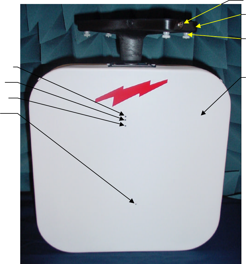
Figure 1. Propagator PCS-1900 Repeater
Green Power LED
Red Fault LED
Down Link LED
Up Link LED
DC Power Jack
Mounting Base
(Rotated)
Nylon Thumb Screws
(Attaches Mounting
Base to Mounting
Plate) 4X
Mobile Side Radome
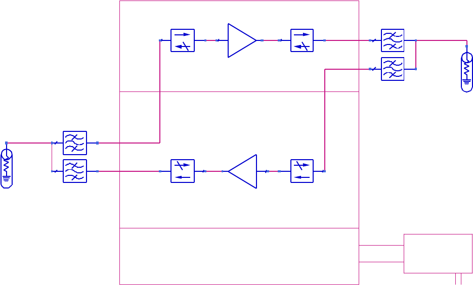
Figure 2. Propagator Repeater Block Diagram
9 V Power
Supply
110 VAC
Power / Interface Circuit
4-1-01
Propagator PCS-1900 Repeater Block Diagram
AntLoad
Mobile_Side_Antenna
BPF_Chebyshev
Mobile_DPX_DL_Filter
BPF_Chebyshev
Mobile_DPX_UL_Filter
AntLoad
Base_Side_Antenna
BPF_Chebyshev
Base_DPX_DL_Filter
BPF_Chebyshev
Base_DPX_UL_Filter
Amplifier
UL_Amp_with_ALC
IsolatorSML
UL_Input_Isolator
IsolatorSML
UL_Output_Isolator
IsolatorSML
DL_Input_Isolator
Amplifier
DL_Amp_with_ALC
IsolatorSML
DL_Output_Isolator
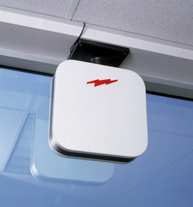
Figure 3. Preferred Window Mounting
Figure 4. Wall Mounted Configuration
Figure 5. Ceiling Mounted Repeaters
Figure 6. Propagator Mounting Plate
Figure 7. Propagator Mounting Base Attached to Mounting Plate
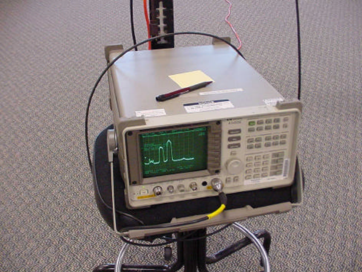
Figure 8. Example of Spectrum Analyzer Display of Base Station Signals for
Stable Operation of the SSR

APPENDIX A. PCS Frequency Band and Blocks
Band/Block
Channel Numbers
Mobil Station Transmit
Frequency (MHz) Base Station Transmit
Frequency (MHz)
A 0-299 1850-1865 1930-1945
D 300-399 1865-1870 1945-1950
B 400-699 1870-1885 1950-1965
E 700-799 1885-1890 1965-1970
F 800-899 1890-1895 1970-1975
C 900-1199 1895-1910 1975-1990

APPENDIX B: Specifications
Model PRB-1900-xx -AD -BE -FC
Rx Freq (MHz) 1850-1870 1870-1890 1890-1910
Rx NF 5 dB Max
Tx Freq (MHz) 1930-1950 1950-1970 1970-1990
Maximum Tx Power at
Antenna Port +11 dBm typical; +14 dBm Max
ACPR (IS-95) -48 dB Min @ ±885 kHz
Power @110VAC 20 watts Max
Temp Range 30 to 95 oF
Total System Gain 73 or 83 dB Typical
Rx/Tx Active Gain 50 or 60 dB selectable
Size 15” X 15” X 4” less Power Supply
Weight 8¾ lbs less Power Supply
APPENDIX C: Gain Adjustment
The standard factory active gain setting for the Propagator is 50dB. Some installation
locations provide a very low multi-path feedback environment and can support a stable active
gain of 60dB. Factory trained service personnel can easily set the gain of the Propagator to
either gain setting using the following procedure:
1) Remove the white plastic radome on the mobile side of the Propagator. This is
accomplished by using a dull pocket knife to first remove the plastic staking pins in
the plastic rivets around the edge of the radome (see Figure C-1). After the staking
pins are removed, the plastic expansion sleeves are easily extracted using the same
dull pocket knife (see Figure C-2).
2) Remove the 4 nylon screws attaching the mobile side antenna circuit board to the
nylon stand-offs on the electronics housing (see Figure C-3).
3) Carefully remove (unplug) the antenna circuit board using the large holes thru the
circuit board adjacent to the RF connector on the bottom side of the circuit board. It
may be necessary to rock the circuit board around after the RF connection is
unplugged to get the circuit board past the 4 plastic LED lenses.
4) The gain setting jumpers are accessible thru two slot openings in the electronics
housing cover (see Figure C-4). The jumpers should be covering both circuit pins for
50dB active gain (see Figure C-5). The jumpers should only be covering one pin for
60dB active gain (see Figure C-6). Set the jumpers for the desired gain in each
channel; the downlink gain set jumper is nearest the mounting base of the Propagator
(see Figure C-7).
5) Reverse steps 1-3 above to re-install the antenna circuit board and the radome.
DO NOT DISTURB THE BRASS DIPLEXER TUNING SCREWS !!!
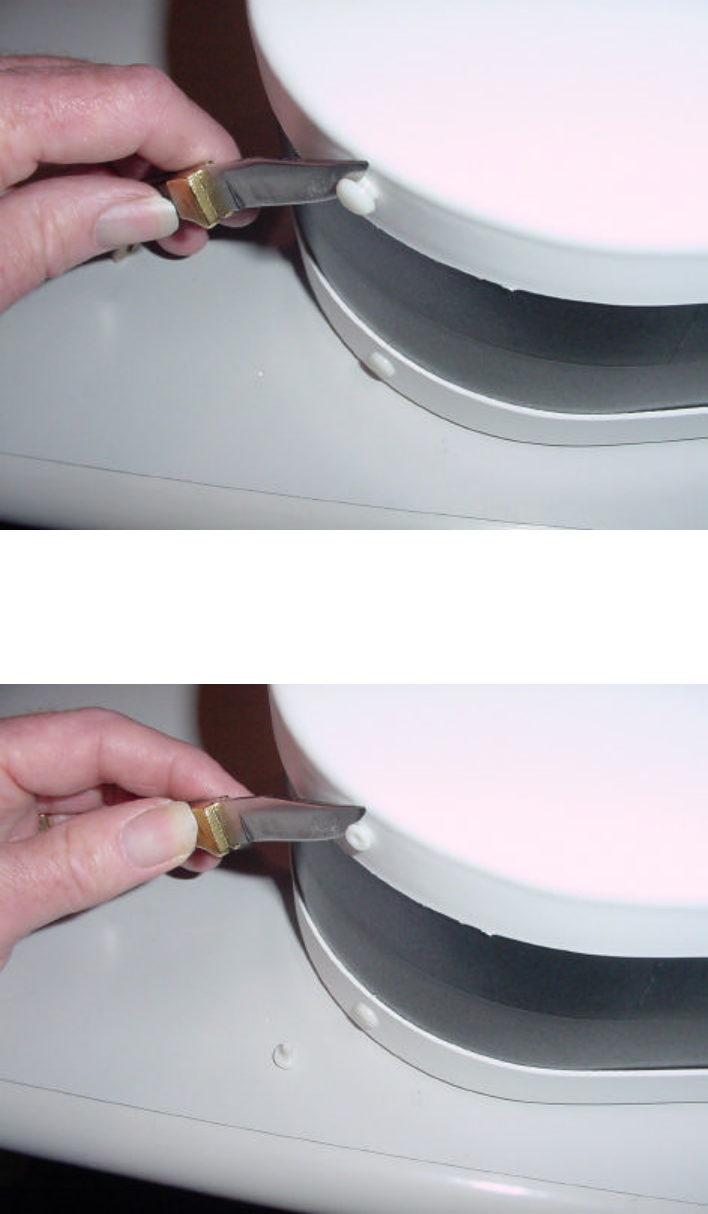
Figure C-1. Plastic Rivet Staking Pin Removal
Figure C-2. Plastic Rivet Expansion Sleeve Removal
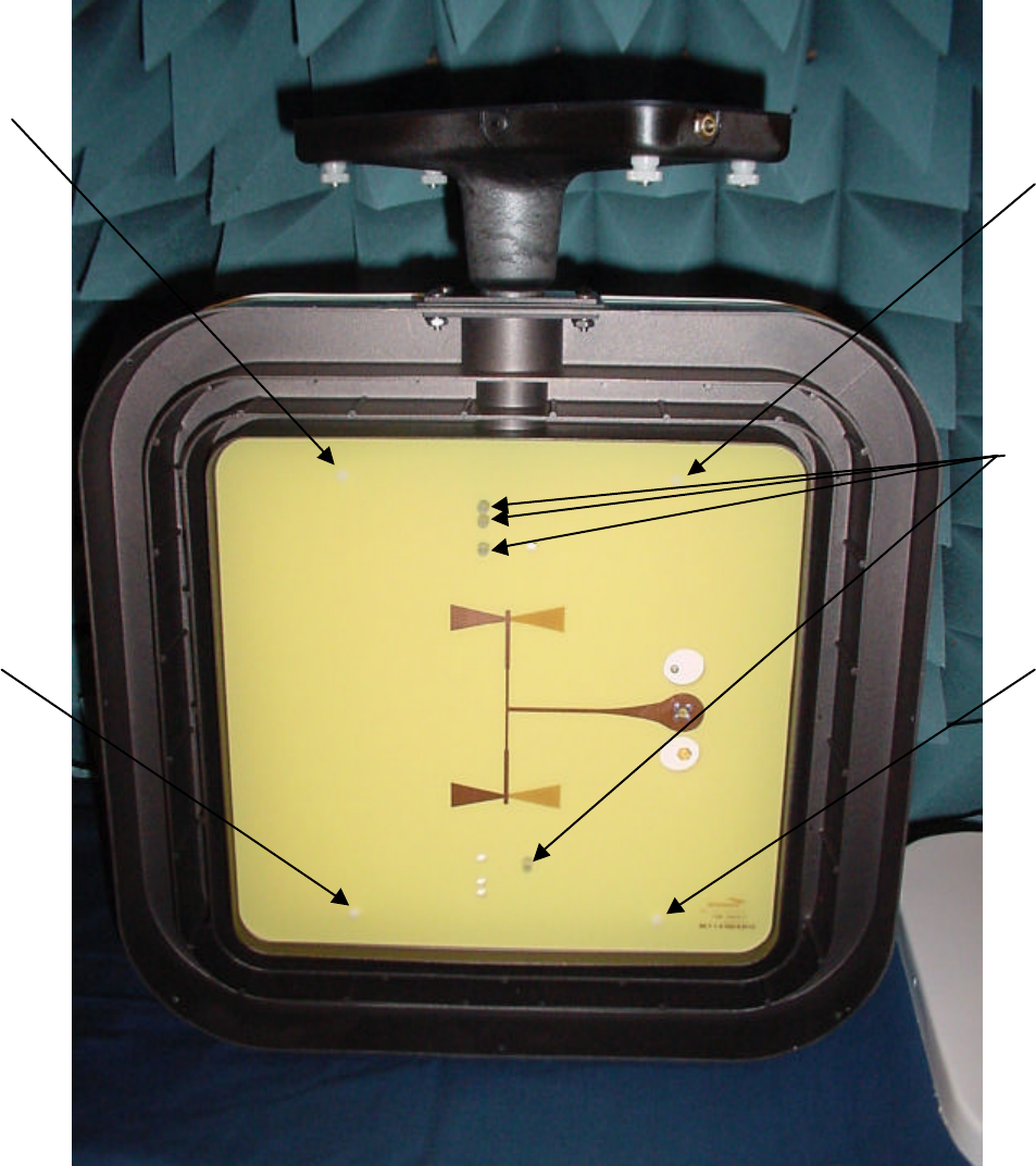
Figure C-3. Nylon Antenna Circuit Board Attachment Screws
and LED Lenses
#1
#2
#3
#4
LED
Lenses
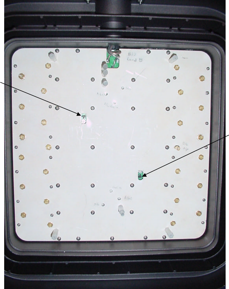
Figure C-4. Gain Setting Jumper Slots
Uplink
Jumper
Downlink
Jumper
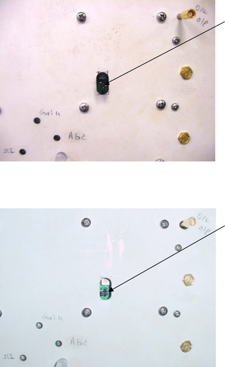
Figure C-5. 50 dB Gain Jumper Orientation (Uplink Slot)
Figure C-6. 60 dB Gain Jumper Orientation (Uplink Slot)
Jumper Covers Both
Circuit Board Pins in
the 50dB Gain Position
Jumper Covers Only
One Circuit Board
Pin in the 60dB
Position