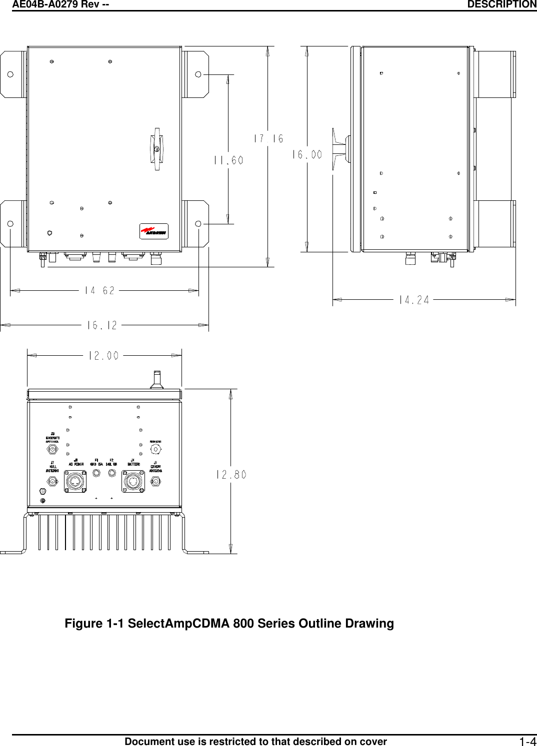
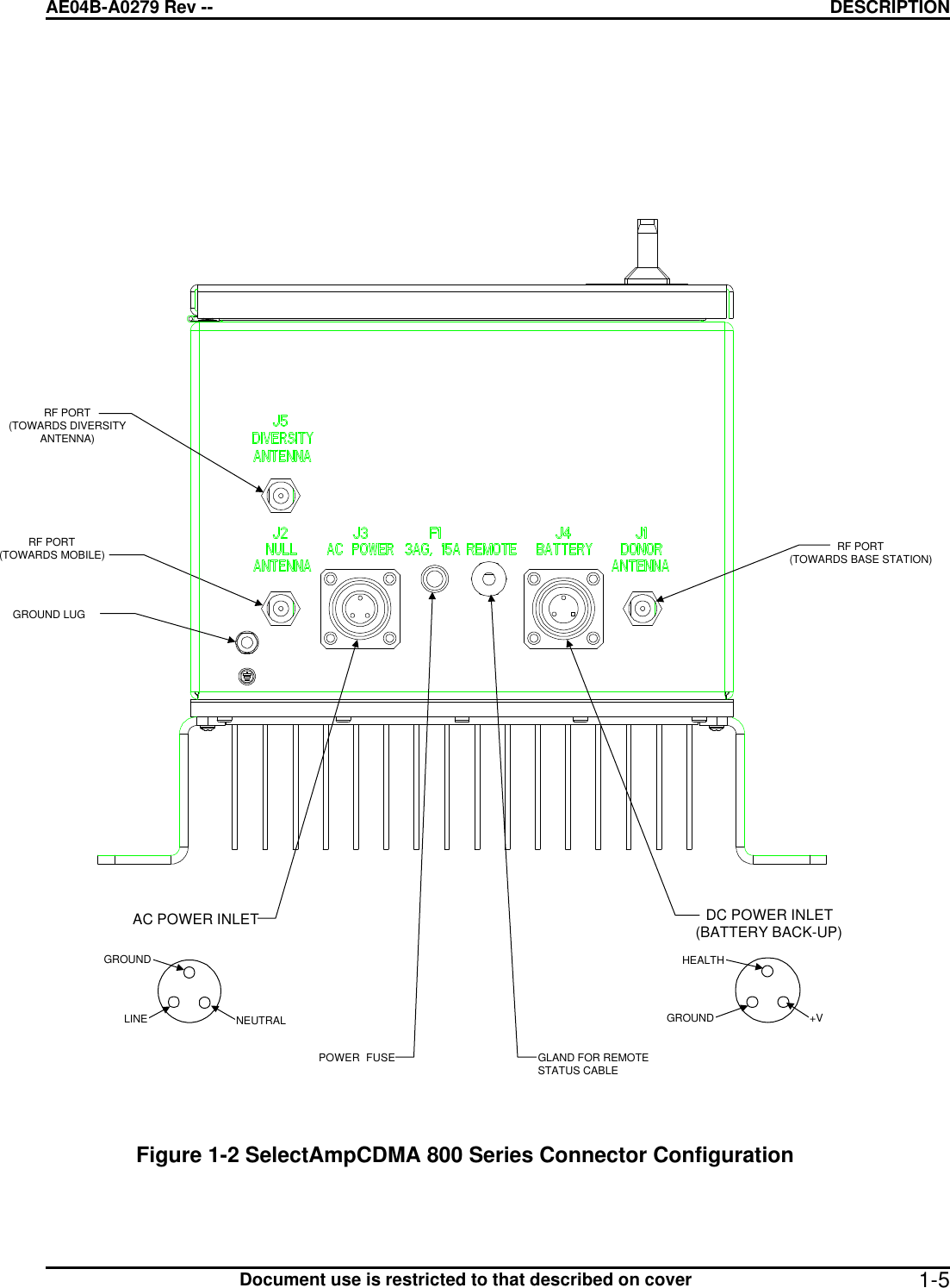
Andrew SELA-800CHZ Extender SelectAmp CDMA 800 Channalized Amplifier User Manual frontPage

Andrew Corporation Extender SelectAmp CDMA 800 Channalized Amplifier frontPage

Exhibit D Users manual per 2 1033 c 3

 27 February, 2001     USERS GUIDE for the SELECTAMP CDMA 800 CHANNELIZED AMPLIFIER    MANUAL NO. AE04B-A0279 REVISION --       The information set forth in this document and all rights in and to inventions disclosed herein, and patents which might be granted thereon disclosing, employing or covering the materials, methods, techniques or apparatus described herein are the exclusive property of Andrew Corporation.  This document is an operation and maintenance manual.  No disclosure or reproduction of the information or drawings shall be made of any other purpose without the prior written consent of Andrew.  Use of the information contained herein to fabricate or assemble any item in whole or in part is expressly prohibited.  These goods are subject to U.S. Department of State, International Traffic in Arms Regulations, 22 CFR 120-130.  This transmitter is intended for use at fixed base station sites only, and is not to be marketed for mobile use.  As such, under Section 1.1307 of the FCC Rules, the transmitter is not currently subject to the Commission’s environmental rules pertaining to the routine evaluation for RF exposure prior to equipment authorization.   2601 Telecom Parkway Richardson, Texas 75082-3521 Phone: 972-952-9700  Fax: 972-952-0019
AE04B-A0279 Rev. -- LIST OF EFFECTIVE PAGES      Document use is restricted to that described on cover i  LIST OF EFFECTIVE PAGES  Dates of issue for original and changed pages are:  Original................... O................. 21 June 2000   TOTAL NUMBER OF PAGES IN THIS PUBLICATION IS __, CONSISTING OF THE FOLLOWING:    Page  Change No.  (O = Original Page)  Title Page  O  List of Effective Pages (i)  O  Safety Summary (ii)  O  Table of Contents (iii - iv)  O  Chapter 1 (1-1 thru 1-5)  O  Chapter 2 (2-1)  O  Chapter 3 (3-1 thru 3-3)  O  Chapter 4 (4-1)  O  Appendix A (A-1 thru A-5)  O  Appendix B (B-1 thru B-15)  O  Appendix C (C-1 thru C-15)  O  Appendix D (D-1 thru D-2)  O
AE04B-A0279 Rev. -- SAFETY SUMMARY      Document use is restricted to that described on cover ii SAFETY SUMMARY  High voltage is used in the operation of this equipment.  Death on contact may result if personnel fail to observe the following safety precautions:    Do not be misled by the term "Low Voltage."  Potentials as low as 50 volts may cause death under adverse conditions.   Do not crush, puncture, disassemble, or otherwise mutilate batteries.  Leaking batteries can cause serious damage to equipment and injury to personnel.   Do not remove covers or access plates on the equipment unless you are authorized to do so.   Do not work on electronic equipment unless there is another person nearby who is familiar with the operation of the equipment and is trained in administering first aid.   Whenever possible, disconnect the equipment from the power source before beginning maintenance.   To prevent electrical shock or damage to the equipment, do not operate it until you thoroughly understand the operation and function of all controls, indicators, and connectors.   Turn off all power to the equipment before replacing any fuses.    FIRST AID   In case of electrical shock:   Do not try to pull or grab the individual.   If possible, turn off the electrical power.   If you cannot turn off the electrical power, pull, push, or lift the person to safety using a dry wooden pole, a dry rope, or some other insulating material.   Send for help as soon as possible.   After the injured person is no longer in contact with the source of electrical shock, move the person a short distance away and immediately administer first aid and artificial resuscitation as required.
AE04B-A0279 Rev. -- TABLE OF CONTENTS      Document use is restricted to that described on cover iii TABLE OF CONTENTS  CHAPTER 1  DESCRIPTION .............................................................................................................. 1-1 1.1 OVERVIEW............................................................................................................................. 1-1 1.2 ELECTRICAL SPECIFICATIONS............................................................................................. 1-1 1.3 MECHANICAL SPECIFICATIONS............................................................................................ 1-2 1.4 ENVIRONMENTAL SPECIFICATIONS .................................................................................... 1-2 1.5 TECHNICAL ASSISTANCE  .................................................................................................... 1-2 CHAPTER 2  OPERATIONAL OVERVIEW ......................................................................................... 2-1 2.1 OVERVIEW............................................................................................................................. 2-1 2.2 RF DISTRIBUTION.................................................................................................................. 2-1 2.3 POWER DISTRIBUTION ......................................................................................................... 2-1 2.4 CONTROL DISTRIBUTION...................................................................................................... 2-1 CHAPTER 3  FUNCTIONAL DESCRIPTION....................................................................................... 3-1 3.1 OVERVIEW............................................................................................................................. 3-1 3.2 FUNCTIONAL DESCRIPTION ................................................................................................. 3-1  3.2.1 Diplexer........................................................................................................................ 3-1 3.2.2 LNA/Attenuator ............................................................................................................ 3-1 3.2.3 Channelizer.................................................................................................................. 3-1 3.2.3.1  Downconverter ................................................................................................ 3-1 3.2.3.2  Upconverter..................................................................................................... 3-2 3.2.3.3  Synthesizer ..................................................................................................... 3-2 3.2.4 Power Supply............................................................................................................... 3-3 3.2.5 Power Amplifier Module ............................................................................................... 3-3 3.2.6 Interconnect Board....................................................................................................... 3-3 3.2.7 Battery Back Up Option ............................................................................................... 3-3 3.2.8 Mounting Kit Options.................................................................................................... 3-3 3.3 PROGRAMMING..................................................................................................................... 3-4 CHAPTER 4 MAINTENANCE ............................................................................................................. 4-1 4.1 MAINTENANCE PROCEDURES ............................................................................................. 4-1    APPENDIX A AMPLIFIER INSTALLATION.........................................................................................A-1 APPENDIX B SOFTWARE INSTALLATION .......................................................................................B-1 APPENDIX C APPLICATION NOTES .................................................................................................C-1 APPENDIX D BATTERY BACK-UP OPTION......................................................................................D-1     LIST OF FIGURES  Figure 1-1  SelectAmp CDMA800 Series Outline Drawing ................................................................... 1-3 Figure 1-2  Connector Configuration.................................................................................................... 1-4 Figure 3-1  Isometric View................................................................................................................... 3-2
AE04B-A0279 Rev. -- TABLE OF CONTENTS      Document use is restricted to that described on cover 1LIST OF TABLES  Table 1-1  Electrical Specifications ..................................................................................................... 1-1 Table 1-2  Mechanical Specifications .................................................................................................. 1-2 Table 1-3  Environmental Specifications.............................................................................................. 1-2
AE04B-A0279 Rev -- DESCRIPTION      Document use is restricted to that described on cover  1-1CHAPTER 1  DESCRIPTION 1.1 OVERVIEW  The SelectAmp CDMA 800 bi-directional channelized amplifier provides selective frequency amplification of user specified frequencies in the SMR, Cellular, and ESMR bands.  This unit will selectively filter for one 1.25 MHz or 5 MHz channel, depending on the part number ordered, in the Uplink and Downlink band as determined by the operator.  Frequency selection, gain adjustment and fault monitoring is accomplished with monitor and control circuitry and firmware.  Within this manual, Uplink refers to the RF signal path from the mobile unit to the base station (Donor Cell) and the Downlink refers to the RF signal path from the base station to the mobile unit.  1.2 ELECTRICAL SPECIFICATIONS  Table 1-1 below contains the electrical specifications for the Channel Selective Amplifier.  Table 1-1  Electrical Specifications   Parameters  Specification  Frequency Range 800 MHz Cellular   Uplink                                                 Downlink 824 – 849 MHz                                   869-894 MHz   Power   Three wire, 90 to 260 VAC @ 200 watts.  SAW Filter 3 dB Bandwidth  1.5 MHz or 5 MHz.  Noise Figure  5 dB maximum.  RF Port Impedance  50 ohms nominal.  Maximum Input Signal Without damage  +10 dBm with no attenuation.  CDMA Power Output  8 Watts Downlink, 1Watt Uplink.  Spurious Emissions per J-STD-008   (Measured from filter center frequency). -45 dBc min @  885 KHz. -13 dBm max @ 1.25 MHz. -45 dBm min @ 1.25 MHz.  In-Band Spurious  -30 dBm or better at maximum gain.  Status  Frequency setting, gain setting, and module failure via  phone interface.  Power Gain Downlink Uplink   65 to 95 dB, adjustable in 2 dB steps. 55 to 85 dB, adjustable in 2 dB steps.
AE04B-A0279 Rev -- DESCRIPTION      Document use is restricted to that described on cover  1-21.3 MECHANICAL SPECIFICATIONS  Table 1-2 below contains the mechanical specifications for the Amplifier.   Table 1-2  Mechanical Specifications  Parameters  Specification   Size  Amplifier: Height: 41 cm (16.3 inches). Width: 31 cm (12 inches). Depth: 31 cm (12 inches). (Excluding heatsinks, connectors, handles, and feet.)  Weight  Amplifier: 45 lbs (21 kg).  Mounting  Four holes spaced (295 x 371 mm) (11.6 x 14.62 inches). Hole diameter = 0.453 inches.  Power Connections  Weather proof 3 Pin Male (AC), 3 Pin Female (DC)  RF Connections  Type N female.  Figures 1-1 and 1-2 show outline mounting and connector locations for the SelectAmp series amplifiers. The Diversity connection is not available on the 2 Watt repeater (CDMA 800-1).  1.4 ENVIRONMENTAL SPECIFICATIONS  Table 1-3 below contains the environmental specifications for the Amplifier.   Table 1-3  Environmental Specifications  Parameters  Specification  Temperature Range (Operating)  Operating: -40 to +60ºC (Vertically mounted with unobstructed airflow.) Storage: -40º to +70ºC.   Humidity Range (Operating)  Up to 90 percent non-condensing.  Environmental Protection  NEMA type 4 (IP 66).   1.5 TECHNICAL ASSISTANCE   Technical assistance on this or any other Andrew product is available 24 hours per day through:  Andrew Customer Service Telephone: 1-800-255-1479 Fax: 1-708-349-5444
AE04B-A0279 Rev -- DESCRIPTION      Document use is restricted to that described on cover  1-3
AE04B-A0279 Rev -- DESCRIPTION      Document use is restricted to that described on cover  1-4 Figure 1-1 SelectAmpCDMA 800 Series Outline Drawing
AE04B-A0279 Rev -- DESCRIPTION      Document use is restricted to that described on cover  1-5  RF PORT(TOWARDS MOBILE)POWER  FUSE GLAND FOR REMOTESTATUS CABLERF PORT(TOWARDS BASE STATION)RF PORT(TOWARDS DIVERSITYANTENNA)AC POWER INLETGROUNDLINE NEUTRALDC POWER INLET(BATTERY BACK-UP)+VHEALTHGROUNDGROUND LUG Figure 1-2 SelectAmpCDMA 800 Series Connector Configuration
AE04B-A0279 Rev -- OVERVIEW      Document use is restricted to that described on cover 2-1  CHAPTER 2  OPERATIONAL OVERVIEW   2.1 OVERVIEW  Refer to Figure 2-1.  The SelectAmp CDMA 800 bi-directional channelized amplifier provides selective frequency amplification of user specified frequencies in the SMR, Cellular, and ESMR bands.  This unit will selectively filter for one 1.25 MHz or 5 MHz channel, depending on the part number ordered, in the Uplink and Downlink band as determined by the operator.  This is accomplished by downconverting the desired signals to a 70 MHz intermediate frequency and using narrowband SAW filters to provide adjacent channel rejection 2.2 RF DISTRIBUTION  The amplifier contains two paths; forward, or downlink, from the base station to the mobile, and reverse, or uplink, from the mobile to the base station.  Each path includes a diplexer, low noise amplifier, channelizer, and power amplifier.  The diplexers and channelizers determine the frequencies to be amplified.  2.3 POWER DISTRIBUTION  Main power for the amplifier is provided by a 14 amp power supply operating at +15 VDC.  The power supply accepts 90 - 260 VAC inputs.  The interconnect board distributes +15 volts, +5 volts, and -5 volts to the various modules.  2.4 CONTROL DISTRIBUTION  The operator has control over the gain and operating frequency of each path.  Computer inputs for gain and channel settings are routed to each low noise amplifier and channelizer.  The gain setting is a four bit word that sets downlink gain from 65 dB to 95 dB, and uplink gain from 55 to 85 dB.  The channel setting is a three wire serial input to a synthesizer in each channelizer.  Each module outputs a status message to indicate the overall condition of the active devices.  If an active device fails, the module reports a fault.
AE04B-A0279 Rev -- OVERVIEW      Document use is restricted to that described on cover 2-2 LNA/ATTENUATORLNA/ATTENUATORCHANNELIZERCHANNELIZER5 WATTPOWER AMP10 WATTPOWER AMPPOWER SUPPLY INTERCONNECT BOARDPOWER/CONTROL BUSPOWER/CONTROL BUSDOWNLINKFILTERUPLINK FILTERDOWNLINKFILTERUPLINK FILTERDIPLEXERDIPLEXERTOANTENNATOANTENNA  FIGURE 2-1 BLOCK DIAGRAM, SELECTAMP CDMA 800 REPEATER
AE04B-A0279 Rev -- FUNCTIONAL DESCRIPTION      Document use is restricted to that described on cover  3-1CHAPTER 3  FUNCTIONAL DESCRIPTION   3.1 OVERVIEW  The SelectAmp CDMA 800 bi-directional channelized amplifier provides selective frequency amplification of user specified frequencies in the SMR, Cellular, and ESMR bands.  This unit will selectively filter for one 1.25 MHz or 5 MHz channel, depending on the part number ordered, in the Uplink and Downlink band as determined by the operator.    This is accomplished by downconverting the desired signals to a 70 MHz IF and using narrowband SAW filters to provide adjacent channel rejection.  3.2 FUNCTIONAL DESCRIPTION  Refer to Figure 3-1.  Each path in the SelectAmp consists of four major modules: diplexers, LNA/attenuator, channelizer, and power amplifier.  These four modules are powered by, interconnected by, and monitored by the power supply, interconnect board, and the status and control module respectively.  Diplexing of the uplink and downlink signals is accomplished by diplexer filters tuned to the required band (SMR, Cellular, or ESMR).  This view shows a third LNA/Attenuator for the diversity option.  These modules perform the function of selecting one 1.25 or 5 MHz channel out of the SMR, Cellular, or ESMR band for amplification.  3.2.1 Diplexer  The diplexer module consists of dual filters with a common port on one end and two separate ports on the other.  One side of the diplexer is tuned for the uplink band, the other side for the downlink band.  Insertion loss of each filter is 2 dB maximum and 65 dB minimum rejection to the opposite band.  3.2.2 LNA/Attenuator  The LNA/attenuator module contains gain stages and digitally controlled attenuators.  The gain of this module is adjustable to permit the overall gain of the downlink path to be adjusted between 65 and 95 dB, and the uplink path to be adjusted between 55 and 85 dB.  3.2.3 Channelizer  The channelizer module contains three boards shielded by aluminum dividers.  These three boards, which are described below, provide the channel selectivity for the SelectAmp.   Overall gain of the Channelizer module is 5 dB.  3.2.3.1 Downconverter  The downconverter board consists of a mixer driven by a synthesizer, and gain stages. The DC current draw of each gain stage is monitored by a window comparator for status.  The window comparator will indicate a fault, if the gain stage has an open or short failure.  The output of the down converter is fed to the upconverter board.
AE04B-A0279 Rev -- FUNCTIONAL DESCRIPTION      Document use is restricted to that described on cover  3-23.2.3.2 Upconverter  The upconverter board mixes the filtered 70 MHz IF with a signal from the synthesizer and outputs  the same frequency that was input to the downconverter.  The upconverter consists of a SAW filter centered at 70 MHz with a 1.5 MHz or 5 MHz 3 dB bandwidth, depending on the part number ordered, a mixer and gain stages.  The DC current draw of each gain stage is monitored by a window comparator.  The window comparator indicates a fault, if the gain stage has an open or short condition.    LNA/ATTENUATORLNA/ATTENUATORCHANNELIZERCHANNELIZER5 WATTPOWER AMP10 WATTPOWER AMPPOWER SUPPLY INTERCONNECT BOARDPOWER/CONTROL BUSPOWER/CONTROL BUSDOWNLINKFILTERUPLINK FILTERDOWNLINKFILTERUPLINK FILTERDIPLEXERDIPLEXERTOANTENNATOANTENNA  Figure 3-1 SelectAmp800 Block Diagram
AE04B-A0279 Rev -- FUNCTIONAL DESCRIPTION      Document use is restricted to that described on cover  3-33.2.3.3 Synthesizer  The synthesizer board consists of a synthesizer circuit that is driven by a reference oscillator and distribution amplifiers.  The synthesizer operating frequency is programmed from the status and control module.  The uplink and downlink frequencies are set with a computer that has Andrew designed frequency control software installed on it.  This software is a Microsoft® Windows™ application that allows the operator to input the desired RF frequency and gain setting.  The status and control module converts the operator's input to the appropriate frequency command for the synthesizer.  The output of the synthesizer is split to the downconverter mixer and upconverter mixer.   3.2.4 Power Supply  The power supply assembly consists of an in-line EMI filter, switching power supply, and interface cable.  The power supply accepts a 90 to 264 VAC input and outputs +15 VDC for use by the rest of the amplifier.  Power is distributed to the active modules through the interconnect board.   3.2.5 Power Amplifier Modules  The downlink power amplifier module provides 45 dB of final gain and is J-STD-008 compliant up to 10 Watts output.   The uplink power amplifer module has 27 dB of gain and is J-STD-008 compliant up to 1 Watt output.  A thermal sensor mounted on the heatsink monitors the total heat dissipation of the power amplifers.   3.2.6 Interconnect Board  The interconnect board distributes power to the other modules, and provides status information and control capabilities at the local and remote connections.  Control functions include synthesizer channel selection and individual channel attenuation settings.  Status information includes module summary status for the LNA/attenuators, channelizers, power amplifiers and battery backup.    3.2.7 Battery Back Up Option   The battery back up (BBU) provides emergency operating power in case of AC power loss.  Under normal conditions, the BBU is charged by an internal charger.  If AC power loss occurs, the BBU automatically comes on-line and this condition is reported to the status and control module. The BBU has been sized for back up capability over the full –40º to +60ºC tempe rature range and will power the repeater for approximately two hours when ambient temperature is –40ºC.  Actual back up time will increase with warmer temperatures.   3.2.8 Mounting Kit Options   A mounting kit (EENCL-90004) is available for ease of installation on walls or poles.  Refer to Appendix A for installation instructions.
AE04B-A0279 Rev -- FUNCTIONAL DESCRIPTION      Document use is restricted to that described on cover  3-43.3 PROGRAMMING  The amplifier and channel number are set by connecting a laptop computer with the supplied cable and adapter to the RJ-45 (see Figure 1-2) port.  Remote access is available by wireline connection to the RJ-11 port.  To set a specific channel number or gain, refer to Appendix B.  The software enclosed with this unit is designed to provide local or remote control capability for one repeater.  A more sophisticated software package is available for monitor and control of a repeater network. Contact customer assistance at the phone number indicated in Chapter 1 for more information.
AE04-A0279 Rev -- MAINTENANCE      Document use is restricted to that described on cover 4-1  CHAPTER 4  MAINTENANCE  4.1 MAINTENANCE PROCEDURES  The SelectAmp contains no user-serviceable parts.  To verify operation, check the amplifier against the electrical specifications provided in Chapter 1.  If the amplifier does not meet these specifications, call 972-952-9894 Monday through Friday, between 8:00 a.m. and 5:00 p.m. CST, for instructions regarding return of the defective unit for repair.
 AE04B-A0279 Rev -- APPENDIXA: AMPLIFIER INSTALLATION      Document use is restricted to that described on cover  A-1APPENDIX A  AMPLIFIER INSTALLATION     1. List of Material • Qty 1 – SELECTAMP800  Amplifier • Qty 1 - User Guide (AE02B-AXXXX) • Qty 1 - Programming Cable (ECATL-80700) • Qty 1 - Adapter, RJ45 to DB9 (AE02M-D0419-001) • Qty 1 - Adapter, RJ45 to DB25 (AE02M-D0420-001) • Qty 1 - Power Cable, 12 ft. (AE02C-D3300-001) • Qty 1 - Diskette containing SMARTpc Lite software for Amplifier Control                         (AE02R-AXXXX-XXX) 2.        Tools Required • Qty 1 - 3/8 in. Electric Drill  • Qty 1 - 3/8 in. Diameter Drill Bit • Qty 1 - 3/8 in. Diameter Masonry Drill Bit • Qty 1 - No. 2 Phillips Screw Driver • Qty 1 - No. 2 Flat Head Screw Driver • Qty 1 - 9/16 Wrench  • Qty 1 - Pair of Medium Wire Cutters • Qty 1 - Laptop Computer • Qty 1 - Amplifier Mounting Kit (EENCL-90004) 3. Determine Location for Amplifier 1. Determine if the amplifier will be mounted on a wall or a pole. 2. If amplifier is going to be mounted on a wall, is it concrete or wallboard? 3. If amplifier is going to be mounted on a pole, what is the diameter of the pole? The                     Amplifier mounting kit will support a pole up to 12 inches in diameter. 4.   Locate the amplifier within 10 feet of a VAC @50/60 Hz Electrical Outlet.
 AE04B-A0279 Rev -- APPENDIXA: AMPLIFIER INSTALLATION      Document use is restricted to that described on cover  A-24. Amplifier Wall Installation, Figure 1.  Figure 1 Wall Mounting      Mounting Unistrut (2)Floating Nut, 3/8"-16  (4)AmplifierBolt, Hex Hd, 3/8"-16 x .75 (4)Flat Washer, 3/8" (4)Mounting Feet (4)
 AE04B-A0279 Rev -- APPENDIXA: AMPLIFIER INSTALLATION      Document use is restricted to that described on cover  A-31. Location found 2. Install the amplifier to the wall using mounting kit 3. Material used from mounting kit for wall installation. • Channel (Qty - 2ea) • Clamp Nut (Qty - 4ea) • 3/8”-16 X .75 Hex Head Bolt • Flat Sealing Washer    4. Materials provided for wall mounting of unistrut. • Anchors (EAHRS-00002) (Qty – 4ea) • Screw, Pan Head, #10-32 X 1.50 (Qty – 4ea) • Washer, #10 (Qty- 4ea) 5. Prepare Unistrut a. Drill two holes (0.219 inches in diameter) in each mounting unistrut. b. The holes should be located between the slots and spaced approximately 12 inches apart, centered in the unistrut. c. Prepare Holes in wall. d. Mark hole locations from modified mounting unistrut. e. Unistruts should be spaced 11.60 inches apart (center to center) f. For wallboard approximately 5/8 in. thick. • Drill 3/8 in. diameter holes • Depress wing tabs so that anchor will fit into hole • Push in until flush with wallboard                   g. Concrete Installation  • Drill 3/8 diameter hole approximately 1 in. deep • Depress wing tabs so that anchor will fit into hole • Push in until flush with outside surface of concrete       h. Mount channels to the Wall • Line mounting unistruts up with the holes drilled in the wall • Use #10 hardware to install i. Install amplifier to Channels • Install the clamp nuts from the mounting kit into the mounting unistrut. • Use the 3/8 hardware supplied with the mounting kit to install the amplifier to the mounting unistrut.
 AE04B-A0279 Rev -- APPENDIXA: AMPLIFIER INSTALLATION      Document use is restricted to that described on cover  A-4  5.  Amplifier Pole Installation, Figure 2.                Figure 2 Pole Mounting  Triangular Mounting Bracket (4)Floating Nut, 3/8"-16 (4)Bolt, Hex Hd, 3/8"-16 x .75  (4)Flat Washer, 3/8" (4)Mounting Feet (4)
 AE04B-A0279 Rev -- APPENDIXA: AMPLIFIER INSTALLATION      Document use is restricted to that described on cover  A-5 1. Find appropriate location for Repeater Installation 2. Install the repeater to a pole using mounting kit 3. Material used from mounting kit. a. Mounting Unistrut (Qty – 2ea) b. Floating Nut (Qty – 4ea) c. Clamp (Qty – 2ea) d. Stainless steel Band Strap (Qty – 2ea) e. Mounting Bracket (Qty – 4ea) f. X .75 Hex Head Screw (Qty – 4ea) g. Washer, 3/8 approximately (Qty – 4 ea) 4. Mount Amplifier to Unistruts 5. Install the floating nuts from the mounting kit into the mounting unistrut. 6. Use the 3/8 approximately hardware supplied with the mounting kit to install the amplifier to the mounting unistrut.  6. Power Up   1. Use the power Cable (AE02C-D3300-001) to connect the amplifier to a power source. 2. The amplifier will accept from 90 – 260 VAC @ 240 Watts 3. If the connector on the cable is not compatible with that of the power source, you may either: a) Find an appropriate adapter. b) Locate the correct connector and splice the cable.  The wiring follows North American standards  • Black Wire – Line • White Wire – Neutral • Green or Green/Yellow Wire – Ground or Earth  7. Alignment and Test  This procedure will allow the installation crew to properly align and test the repeater system.   This procedure assumes the antennas and cables are properly aligned and operating correctly.  1. Connect a spectrum analyzer to the donor antenna cable.  Adjust the analyzer for a convenient display of the BTS signal, and record the received signal level.   Received Signal Level __________dBm
 AE04B-A0279 Rev -- APPENDIXA: AMPLIFIER INSTALLATION      Document use is restricted to that described on cover  A-62. Connect a signal source to the null antenna.  Make sure the frequency of the signal source is well away from the BTS frequency, and set the source power level to 0 dBm.  Set the spectrum analyzer to the signal source frequency and measure the power level at the Donor antenna cable.  The difference between the signal source power and the spectrum analyzer power level reading is the antenna isolation in dB.  Record the values. Signal Source Level ________ dBm Spectrum Analyzer Level ________ dBm Isolation ________   dB  The isolation value determines the maximum amount of gain allowed for either downlink or uplink path.  For the best stability of the system under all conditions, the repeater gain in the uplink or downlink should be at least 10 dB less than the isolation measured.  3. Initial Downlink Gain Setting  THE OUTPUT POWER OF THE EITHER PATH MUST NOT EXCEED THE SPECIFIED RATING.  IF THE SPECIFIED RATING IS EXCEEDED, THE UNIT MAY NOT BE FCC COMPLIANT FOR SPURIOUS EMISSIONS.  Connect the spectrum analyzer to the NULL port of the repeater.  Remember, the power rating of the repeater is quite high and there is risk of exceeding the spectrum analyzer maximum input.  Place attenuators as required on the spectrum analyzer input.  Connect the Donor antenna to the DONOR  port of the repeater.  The downlink output power of the repeater is equal to the input level measured in Step 1 above, plus the repeater gain.  Initially, set the repeater gain so that it meets the isolation criteria specified in Step 2 without exceeding the output power specified in Chapter 1, Table 1-1.  4. Initial Uplink Gain Setting The uplink gain is completely dependent on the system design, and can only be determined through drive testing.  It is recommended that the gain be set to minimum, and increased as required to meet system performance requirements.  5. Once the initial settings are made, drive testing is recommended to verify proper coverage.
AE04B-A0279 Rev -- APPENDIX B:  SOFTWARE INSTALLATION        Document use is restricted to that described on cover B-1 APPENDIX B SOFTWARE INSTALLATION   1. Tools required  One personal computer (PC) with Windows 95, 98, or Windows NT.  2. SMARTpc Lite Software Installation and Configuration 2.1 Overview 2.1.1 The SMARTpc software provides a means to control and monitor the SelectAmp800 series (and other Smart-equipped Andrew products) locally or from a remote site.  2.1.2 The application software runs on a PC under Windows and communicates with firmware inside the SelectAmp800.  2.1.3 Local connections require a programming cable which is provided with the SelectAmp800. 2.1.4 Remote connections require a PC accessible modem. 2.2 Installation/Configuration Instructions 2.2.1 Install the Software on the PC. 2.2.1.1 Insert the installation disk into floppy drive. 2.2.1.2 Run the setup.exe executable located on the installation disk. 2.2.1.3 The default installation directory is c:\smartpc, but the setup program prompts you in order to allow a different installation directory. 2.2.1.4 After setup is completed, there should be a new program group called SMARTpc Lite.
AE04B-A0279 Rev -- APPENDIX C:  APPLICATION NOTES      Document use is restricted to that described on cover  C-1APPENDIX C  APPLICATION NOTES   The Andrew SelectAmp800 is a two-way on-band repeater with two RF paths.  One path is for connection to an antenna directed towards the service providers base station (this would usually be a Yagi or some other directional antenna).  The other path is connected to an antenna or suitable leaky feeder cable directed over the area in which the mobile units are to be found.  Typical applications for the amplifier are as follows:  1. Extending coverage to within tunnels.  This is achieved by the use of a leaky feeder cable running the length of the tunnel attached to the mobile port of the amplifier. A directional antenna would be connected to the base port of the amplifier directed towards the base station. In this way uninterrupted coverage can be extended to within the tunnel. In some cases a Yagi or omni-directional antenna can be used.  2. Extending coverage to within buildings.  Many modern buildings incorporate large amounts of reinforced concrete and other metal in their construction and, therefore, act as effective screens to penetration by RF signals.  By using localized antenna or leaky feeders within these buildings connected to the mobile port, and a Yagi on the top of the building connected to the base port, coverage can be extended to within these buildings.  3. Local topology, e.g., hills, embankments, etc., can cause propagation blank spots.  By using  a suitable antenna to cover the area and a Yagi mounted high enough to "escape" the blank spot, coverage can be extended to these areas.  4. Temporary requirements for radio coverage can arise from such events as conferences,, exhibitions, sporting events, etc.  These short term events would not justify the expense of a permanent base station.  Therefore, an amplifier can be employed to "borrow" channels from a less busy site some distance away that would otherwise be out of range of mobiles units at the event.  5. If a site becomes heavily congested with radio traffic and a neighboring site is under-utilized, an amplifier can be utilized to "borrow" channels from the quiet site for use in the coverage area of the busy site.  6. In areas of low user density, a base station can be under-used.  However, it is often  impossible to increase coverage from a central point which experiences limits on power levels, mast heights etc.  In these instances an amplifier placed some distance away from the base station can be used to extend the coverage in a desired direction.        When siting the two antennas for an amplifier, the most important requirement is to maintain the RF isolation
AE04B-A0279 Rev -- APPENDIX C:  APPLICATION NOTES      Document use is restricted to that described on cover  C-2between the antennas to substantially greater than the gain of the amplifier (otherwise, feedback and oscillation will occur).  The isolation can be achieved in many ways including:  1. Physical separation using long feeders to keep the two antennas apart. 2. Directional antennas can be used, if the base station and the mobiles are on opposite sides of the amplifier.  3. Vertical separation can be used by mounting the base station antenna high up a mast and the mobile antenna as low as possible angled downwards to separate the two field patterns.  It is also necessary when siting the antennas to ensure that the maximum input signals to the amplifier do not exceed the limits for the particular unit being used.  If excessive signals do occur, overloading of the amplifier can result in poor intermodulation and signal to noise performance.
AE04B-A0279 REV-- APPENDIX D:BATTERY BACK-UP      Document use is restricted to that described on cover  D-1APPENDIX D  BATTERY BACK-UP OPTION  1. OVERVIEW  The SelectAmp series repeaters can be provided with an optional battery back-up, 65ACCE-XXXX-000.  This unit is designed to provide the repeater with a minimum of two hours of operation after loss of AC power. This two-hour life rating is for full current draw at –40oC, so the actual operating life will be dependent on traffic load and ambient temperature at the time the battery back-up is engaged.  The unit contains two batteries, a battery charger, and ancillary components for internal temperature control.  There are two external connections, one for AC power and one for DC interconnect between the battery back-up and the repeater. The connections are opposite sex to reduce the possibility of swapping power inputs.  A 12 foot AC power cord and a 6 foot DC interconnect cable is shipped with the unit.  2. INSTALLATION  CAUTION   THIS UNIT IS EXTREMELY HEAVY. USE CARE WHEN LIFTING.  CAUTION  Installation requires only sufficient structural strength of the installation site to support the weight of the unit.  The unit should be mounted within 10 feet of an AC power source, and within 5 feet of the repeater.   3. ELECTRICAL SPECIFICATIONS  Table 1-1 below contains the electrical specifications for the battery back-up.   Table 1-1  Electrical Specifications   Parameters  Specification  Input Power (max charging current at -40oC)  Three wire, 85 to 132 VAC, 57 –63 Hz, @ 519 watts   Output Power (max)  +12VDC at 14 Amperes  Battery Life,  full current at -40oC  2 Hrs. minimum
AE04B-A0279 REV-- APPENDIX D:BATTERY BACK-UP      Document use is restricted to that described on cover  D-24. MECHANICAL SPECIFICATIONS  Table 1-2 below contains the mechanical specifications for the battery back-up.   Table 1-2  Mechanical Specifications  Parameters  Specification   Size  Height: excluding lifting eyes. Width:  Depth:    Weight   Mounting Flange   5. ENVIRONMENTAL SPECIFICATIONS  Table 1-3 below contains the environmental specifications for the SelectAmp800.   Table 1-3  Environmental Specifications  Parameters  Specification  Temperature Range (Operating)  Operating: -40 to +60EC  Storage: -40E to +70EC.  Humidity Range (Operating)  Up to 90 percent non-condensing.  Environmental Protection  NEMA type 3R

Navigation menu