AngioDynamics UK AS0670 Diomed RFID Module type AS/0670 User Manual Equipment
AngioDynamics UK Limited Diomed RFID Module type AS/0670 Equipment
Contents
- 1. Module user manual
- 2. Equipment user manual
Equipment user manual

Section Version
Welcome B.2
Safety & Warning B.2
Operating Instructions B.2
Procedures B.2
Technical Information B.2
Guarantee B.2
Manufactured in the United Kingdom by DIOMED Limited
DIOMED is a Registered Trademark of DIOMED Ltd. 2005 DIOMED Ltd.
DIOMED DELTA 15/30
DIODE LASER
OPERATOR MANUAL
Version B.2 July 2005 MAN/26/0068
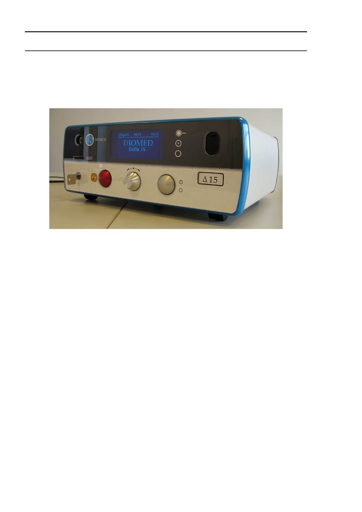
DELTA 15/30
DELTA 15/30 Operator Manual Page 1.2 Version B.2
SECTION 1 WELCOME
Thank you for purchasing a DIOMED laser. This is a high quality medical instrument that will give many
years of service if used and cared for according to the instructions in this operator manual.
Before going any further it is important that the Product Information on page 1.4 is completed at
installation. The Guarantee Registration Certificate and Guarantee Form in section 5 must also be filled
in and the form returned to DIOMED to complete the registration process.
INTRODUCTION
This manual describes the operation of the DIOMED DELTA 15
and the DIOMED DELTA 30, (referred
to as DIOMED DELTA 15/30
in this manual). These lasers are to be used only by experienced, trained
operators familiar with laser procedures.
Before using this instrument for the first time, read the Safety & Warnings section and the Operating
Instructions.
The operator must become familiar with all the controls before commencing any
therapy.
DIOMED DELTA 15
The DIOMED DELTA15
is a diode laser capable of delivering up to 15W of
continuous wave radiation via an optical fiber, or 119J/cm² of pulsed radiation
via a spot handpiece, coupled to the laser aperture.
The DIOMED DELTA 15
incorporates a Class IV GaAlAs (Gallium Aluminium
Arsenide) diode lasers with a wavelength of 810nm (±20nm).
The DIOMED DELTA 15
incorporates a visible Class IIIa diode laser aiming
beam with a wavelength of 635-660nm and a maximum power output of 5mW.
DIOMED DELTA 30
The DIOMED DELTA 30
is a diode laser capable of delivering up to 30W of
continuous wave radiation via an optical fiber, or 400J/cm² of pulsed radiation
via a spot handpiece, coupled to the laser aperture.
The DIOMED DELTA 30
incorporates Class IV GaAlAs (Gallium Aluminium
Arsenide) diode lasers with a wavelength of 810nm (±20nm).
The DIOMED DELTA 30
incorporates a visible Class IIIa diode laser aiming
beam with a wavelength of 635-660nm and a maximum power output of 5mW.

DELTA 15/30
DELTA 15/30 Operator Manual Page 1.3 Version B.2
DESCRIPTION OF THE DIOMED DELTA 15/30
The DIOMED DELTA 15/30 has been designed for use with the DIOMED range of procedure kits, such
as those for EVLT (EndoVenous Laser Treatment). It can also be used with a wide range of standard
fibers and accessories, further details of which are in section 4 of this manual.
The DIOMED DELTA 15/30 consists of three main components:
• The main enclosure houses the laser module containing the optics, heatsink, microprocessor-
based control electronics and power supplies
• The footswitch to activate the laser output when in READY mode
• The fiber or handpiece for delivering the laser radiation to the tissue
Key features of the DIOMED DELTA 15/30 include:
• 15W or 30W power output
• Compact & portable
• Intuitive user interface
• Automatic procedure recognition when used with fibers and accessories conforming to the
DIOMED FRS fiber system
• Minimal maintenance & service
• Internal power calibration meter (optional on DIOMED DELTA 15)
ABOUT THIS MANUAL
This manual is broken down into five main sections as described below. The contents of each one are
detailed at the beginning of the appropriate section.
1 Welcome
2 Safety & Warnings Explains the general warnings and precautions that must be followed to
ensure that the DIOMED DELTA 15/30 is used in a safe manner.
3 Operating Instructions Detailed instructions on how to install and operate the DIOMED DELTA
15/30 laser.
4 Procedures Specific information about DIOMED fibers and procedure kits, equipped
with FRS.
5 Technical Information This section explains all the maintenance procedures that can be
performed by the user.
6 Guarantee Contains the DIOMED guarantee policy and your guarantee certificate.
Ensure that the accompanying form is returned to DIOMED and that the
certificate is kept in a safe place.

DELTA 15/30
DELTA 15/30 Operator Manual Page 1.4 Version B.2
PRODUCT INFORMATION
Laser Serial Number ...............................................................................................................................
Software Version ....................................................................................................................................
(Note: This information is shown on the screen displayed at start-up.)
Date Installed .........................................................................................................................................
Installed by ..............................................................................................................................................
Signed ....................................................................................................................................................
Print Name .............................................................................................................................................
Organisation ...........................................................................................................................................
For service, parts or repair, contact your local DIOMED representative:

DELTA 15/30
DELTA 15/30 Operator Manual Page 2.1 Version B.2
SECTION 2 SAFETY & WARNINGS
CONTENTS
Section 2
SAFETY & WARNINGS ....................................................................................................... 1
Contents ................................................................................................................................................. 1
Symbols used in this manual.................................................................................................................. 2
Warnings................................................................................................................................................. 3
Safety classifications, hazards and precautions..................................................................................... 5
Eye Injury................................................................................................................................................ 7
Burns ...................................................................................................................................................... 8
Reflection Warning ................................................................................................................................. 8
Explosion Hazard Warning..................................................................................................................... 8
Vapor Plume........................................................................................................................................... 8
Clinical Indications & Contra-Indications................................................................................................ 9
Clinical Warnings.................................................................................................................................. 11
Clinical Precautions.............................................................................................................................. 12
Safety labelling ..................................................................................................................................... 13
Safety features ..................................................................................................................................... 14
EMC Declaration .................................................................................................................................. 15
ESD Precautionary Procedures............................................................................................................ 20
FCC Declaration ................................................................................................................................... 20
DELTA 15/30
DELTA 15/30 Operator Manual Page 2.2 Version B.2
SYMBOLS USED IN THIS MANUAL
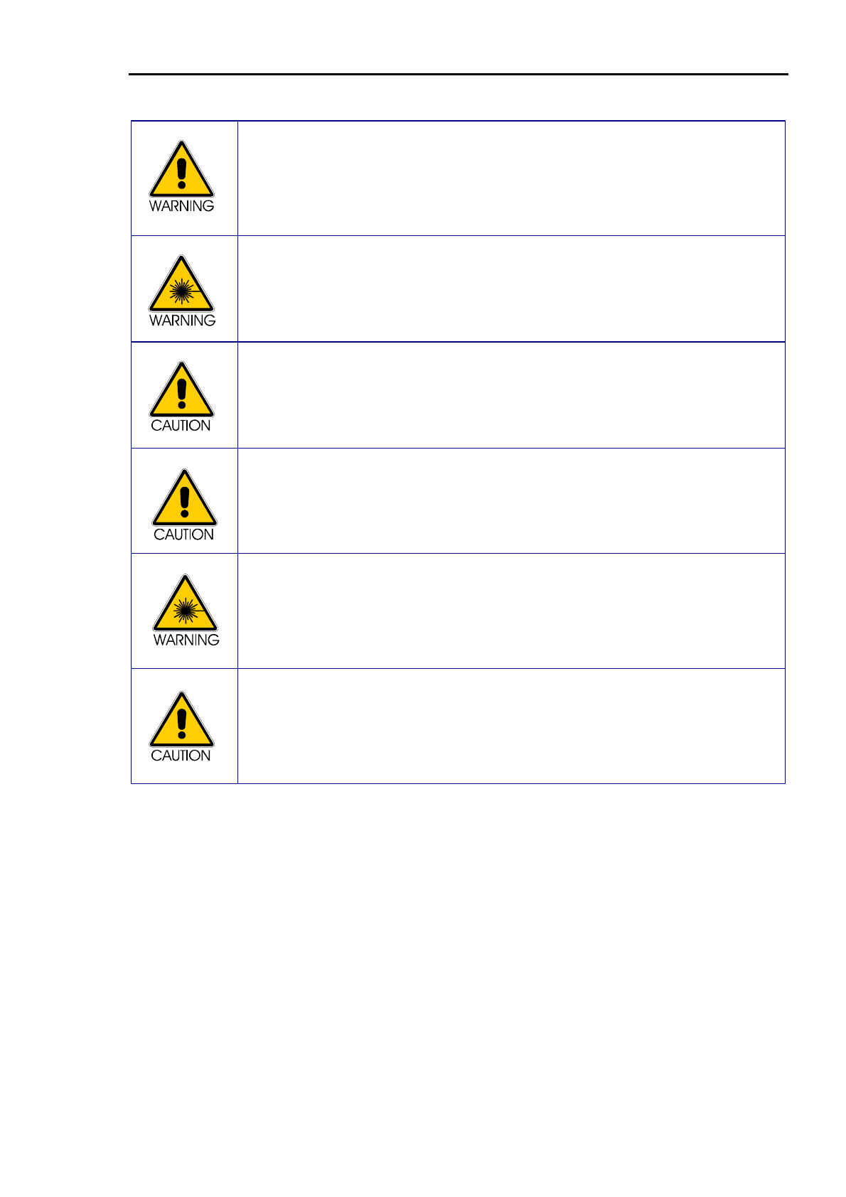
This symbol indicates caution should be taken, as there may be a potentially
hazardous situation that could result in injury to personnel or damage to the
equipment.
This symbol indicates the possibility of a non-radiation hazard that may result in severe
injury to personnel within the vicinity of the equipment.
This symbol indicates the possibility of an electrical hazard that could cause injury to
personnel within the vicinity of the equipment or damage to the equipment.
This symbol indicates the possibility of exposure to hazardous laser radiation that
could cause injury to personnel within the vicinity of the equipment.
This symbol indicates personnel within the vicinity of the equipment should wear
appropriate eye protection.
This symbol indicates an important point to be noted.
DELTA 15/30
DELTA 15/30 Operator Manual Page 2.3 Version B.2
WARNINGS
US Federal Law restricts the use of this device to sale by or on the order of a
physician.
Intended for use only by trained physicians/surgeons familiar with laser procedures.
Use of controls or adjustments or performance of procedures other than those
specified herein may result in hazardous radiation exposure.
This product must be stored at temperatures between 0°C and +55°C. If stored at
temperatures below 10°C for a period of time, the l aser requires up to 12 hours to
acclimatise, prior to operation.
Failure to observe this could result in invalidation of the guarantee.
The laser is not designed to operate at temperatures below 10°C.
The Optical Power Calibration meter, if fitted, is to be used only to calibrate a fiber or
spot handpiece in accordance with the instructions detailed in this manual.
Under no circumstances may it be used as a beam dump, as this will result in
damage to the instrument.
This product contains a lithium battery, which should only be replaced by authorised
service personnel.
Replace the battery only with the same or equivalent type. Dispose of used batteries
according to the manufacturer’s instructions and local disposal requirements.

DELTA 15/30
DELTA 15/30 Operator Manual Page 2.4 Version B.2
EMC Warning
Medical electrical equipment needs special precautions regarding EMC and needs to be installed and
put into service according to the EMC information provided.
The DIOMED DELTA 15/30
may be interfered with by other equipment, even if that other equipment
complies with CISPR emission requirements.
Portable and Mobile RF communications equipment can affect medical electrical equipment.
The DIOMED DELTA 15/30 should not be used adjacent to or stacked with other equipment and that if
adjacent or stacked use is necessary, the DIOMED DELTA 15/30 should be observed to verify normal
operation in the configuration in which it will be used.
If Electromagnetic interference is experienced, relocate or re-orientate the DIOMED DELTA 15/30
or
the other equipment.
Accessories, transducers and cables other than those specified, with the exception of
transducers and cables sold by the manufacturer of the DIOMED DELTA 15/30
as replacement
parts for internal components, may result in increased emissions or decreased immunity of the
DIOMED DELTA 15/30. ‘Immunity’ is the ability of a device to function normally when operated
in the presence of electromagnetic radiation.
The following Cables are compatible with the DIOMED DELTA 15/30
:
• Foot Switch Assembly
Diomed part no. AS1/A0/0002
• Remote Interlock Lead (if required).
Lemo connector (supplied with laser): Diomed part no. CON/51/0003
Ferrite sleeve (Farnell part no. 898-454).
Screened twisted pair cable 7/0.2 (Farnell part no. 140-457).
Note: The ferrite sleeve should be fitted to the remote interlock cable, at a maximum of 75 mm
from the Lemo connector.
• Remote Interlock Bypass (supplied with laser).
Diomed part no. AS1/A3/0024
• IEC Mains Lead (supplied with Laser)
Diomed part numbers: CBL/02/0002, CBL/02/0040, CBL/02/0042, CBL/02/0046,
CBL/02/0051, CBL/02/0063.
DELTA 15/30
DELTA 15/30 Operator Manual Page 2.5 Version B.2
SAFETY CLASSIFICATIONS, HAZARDS AND PRECAUTIONS
This product is classified as a Class IV laser product in compliance with FDA 21
CFR 1040.10 and 1040.11, UL 60601-1, EN 60601-1, EN 60601-1-2, EN 60601-
2-22 and EN 60825-1.
This product conforms to the requirements of Council Directive 93/42/EEC of the
Council of European Communities (Medical Devices Directive). Affixing the ‘CE
Mark’ to the instrument indicates conformity to this directive.
0086
The local Laser Safety Officer should review all procedures for safety prior to system use.
A Class IV Laser is hazardous to the eye from the direct beam and diffuse reflections. It
also presents significant skin and fire hazard.
Avoid eye or skin (except specific treatment) exposure to direct or scattered radiation.
Take all necessary protective measures, as explained in the rest of this section, in areas
where the laser is being used.
All personnel must wear approved protective glasses appropriate to the wavelength of the
DIOMED DELTA 15/30
to reduce the risk of eye damage.
The aiming beam is a Class IIIa Laser and an unprotected eye may view the beam
scattered from a non-reflective surface. Do not stare into the aiming beam or view it
directly with optical instruments.
Avoid directing the laser beam anywhere other than the treatment area or calibration
ports.
Before using a fiber, check it carefully for any signs of damage during storage or transit.
Protective caps should be in place over SMA connectors. All screws and ports should be
secure. Do not use if there is any sign of damage.

DELTA 15/30
DELTA 15/30 Operator Manual Page 2.6 Version B.2
The DIOMED DELTA 15/30 Laser is a portable laser weighing 11kg. All standard safety
procedures for lifting should be applied when moving the instrument.
There are no user serviceable parts in the
DIOMED DELTA 15/30
Laser. The exterior
cover should only be removed by a trained and authorised laser service technician.
Pins of connectors identified with the Electrostatic Discharge (ESD) warning
symbol should not be touched. Connections should not be made to these
connectors unless the ESD precautionary procedures detailed in Appendix D are
followed.
It is recommended that all staff receive an explanation of the ESD warning
symbol and made aware of the ESD precautionary procedures described at the
end of this section.

DELTA 15/30
DELTA 15/30 Operator Manual Page 2.7 Version B.2
EYE INJURY
Extreme caution should be taken when operating the DIOMED DELTA
15/30 near the eyes.
Near infrared light (810nm) from the DIOMED DELTA 15/30 passes through the
transparent components of the eye and is focused on the retina at the back of
the eye. This light can therefore cause an accidental retinal burn.
All personnel must wear approved protective glasses to reduce the risk of eye
damage. The patient should wear protective glasses when not anesthetised. If
the patient is anesthetised, the eyelids should be taped shut and covered with
moist gauze pads.
The local Laser Safety Officer should review all procedures for safety prior to
system use.
All protective glasses should be designed for protection from continuous wave
laser radiation in the wavelength range 790 – 830nm.
The degree of optical filtration (Optical Density or OD) depends on the
application and should be assessed and approved by the appointed Laser
Safety Officer for the establishment.
The recommendations of European Standards EN 60825-1 or EN 207 are
appropriate to assessing laser eye risk. Note that the standards assume a
viewing distance from the source of light of more than 100mm.
DIOMED supplies laser safety glasses marked in accordance with EN 207 as
L5 or greater. Contact your local DIOMED distributor if these are required.
The ‘Nominal Ocular Hazard Distance’ is 8 metres.
Use of optical accessories and viewing aids, which may increase the eye
exposure beyond a safe limit, should be subject to the approval of the Laser
Safety Officer.
Never look directly into the laser aperture even if wearing safety glasses.
Serious eye injury could result.
DELTA 15/30
DELTA 15/30 Operator Manual Page 2.8 Version B.2
BURNS
Irradiation of any substance or material other than the target tissue may result in
a laser burn.
REFLECTION WARNING
Avoid placing reflective materials such as glass, metals and polished plastic in
the beam.
EXPLOSION HAZARD WARNING
Avoid using flammable or explosive anesthetic gases that may be ignited by the
laser. Avoid using other flammable or fume-emitting substances (e.g. ether,
iodine solution, collodion, and alcohol) in the operative field.
VAPOR PLUME
DIOMED recommends that a smoke evacuator or in-line filter be used when
lasing.
Caution – Laser Plume may contain viable tissue particulates.

DELTA 15/30
DELTA 15/30 Operator Manual Page 2.9 Version B.2
CLINICAL INDICATIONS & CONTRA-INDICATIONS
Indications The DIOMED DELTA 15/30 is intended for the following contact or non-contact
laser procedures:
• Incision (only contact)
• Excision (only contact)
• Vaporisation
• Coagulation / haemostasis
- of soft tissue in Endovascular, open and endoscopic procedures in Vascular
Surgery, General Surgery, Gynaecology, Urology, Otorhinolaryngology
(ENT)/Head & Neck Surgery, Ophthalmology (oculoplastics),
Pulmonology/Thoracic surgery, Plastic Surgery, Gastroenterology and
Neurosurgery.
Recommended power levels for the above indications for contact fiber
accessories are between 5-30W and for non-contact fibers, 10-30W.
Beginning at low power (5-10W) with short pulse duration, the surgeon should
note the surgical effect and increase power or pulse duration until the desired
surgical effect is obtained.
Generally, the power requirement will vary depending on the contact fiber core
and tip size. Less power will be required to obtain tissue reaction with smaller
diameter fibers. Recommended power settings are less important than the visual
effect. Changes in tissue texture and colour are the best indications of the laser
effect. Specific pulse duration is not recommended, but is left to user preference
and best medical judgement dependent on the particular application and tissue
type.

DELTA 15/30
DELTA 15/30 Operator Manual Page 2.10 Version B.2
Contraindications
The DIOMED DELTA 15/30 should only be used in conditions where its use is
appropriate and of proven efficacy. It should never be operated except under the
direct supervision of a trained operator.
The potential for complications encountered in surgical laser procedures will
be the same as those encountered in any surgical procedures. These
complications may be serious and could result in death.
Complications may include:
• Pain
• Fever and Leucocytosis
• Bleeding
• Sepsis
• Perforation
(This is not an exhaustive list.)
Potential complications may be encountered in laser procedures, particularly if
inappropriate Fluence settings are used.
Complications in extreme cases may include:
• Pain
• Perforation
• Oedema
• Erythema
• Crusting
• Hyper-pigmentation
• Hypo-pigmentation
• Scarring
(This is not an exhaustive list.)
DELTA 15/30
DELTA 15/30 Operator Manual Page 2.11 Version B.2
CLINICAL WARNINGS
Diode laser radiation, like Nd:YAG laser radiation, penetrates significantly
deeper than CO
2
or argon lasers. Caution should be employed until the
biological interaction of the laser energy with tissue is fully understood by the
operator.
Tissue damage could occur if excessive Power/Fluence is used. Use low power
and short pulse duration settings until fully familiar with instrument capabilities
and tissue response.
As with any conventional surgical operations, adverse reactions may occur
following treatment.
Use cautiously with patients who have had difficulty with previous laser
procedures.
The DIOMED DELTA 15/30 should be used only on tissue that is fully
observable. Do not use the laser if the desired field is not visible, either directly
or via an imaging modality such as ultrasound.
Do not use coaxial gas/air coolant for non-contact fibers when there is a risk of
air/gas embolism.
Do not use the laser close to large blood vessels or in highly vascularised areas,
except when these are the target for the laser treatment.
When performing endoscopic surgery it is vital for the surgeon to appreciate that
the view provided to the surgeon is monocular (not binocular) and depth
perception is decreased. Experience and training in laparoscopic techniques
are strongly recommended prior to clinical use.
During ENT procedures, laser safe endotracheal tubes should be used.

DELTA 15/30
DELTA 15/30 Operator Manual Page 2.12 Version B.2
CLINICAL PRECAUTIONS
General Precautions
Only operators who have been trained in the use of lasers and are thoroughly
familiar with this Operator Manual should use the DIOMED DELTA 15/30. The
information provided in this section is not intended to be all-inclusive and it is not
intended to replace operator training or experience. Please contact DIOMED Ltd.
or your DIOMED DELTA 15/30 distributor for training materials available on the
use of this equipment.
Although it is difficult to specify the effect that the use of the diode laser will have
in each therapeutic situation, it is possible to give a general overview as to what
the clinician might expect when using the DIOMED DELTA 15/30. The exact
effect depends upon the chosen procedure and, especially when using the laser
with manual settings, the Power/Fluence setting, Pulse Duration, Pulse Interval,
Spot size (if applicable) and the tissue type being treated.
The diode laser may cause tissue damage if improperly used. Precautions, such
as careful assessment of the target tissue during treatment and the use of
appropriate Power/Fluence and Pulse Duration, should be taken. Use low
Power/Fluence and short Pulse Duration settings until fully familiar with the
instrument’s capabilities.
Starting at low powers, the operator should note the effect on the tissue and
increase Power/Fluence, Pulse Duration or treatment time until the desired effect
is obtained.
Specific parameters are not recommended, but are left to operator preference
and best medical judgement dependent on the particular application.
The diode laser may not be effective for coagulation for severe haemorrhages.
The operator must be prepared to control haemorrhages with strident, alternative
non-laser techniques. In contact surgery, the tissue interaction with the DIOMED
DELTA 15/30 laser is similar to Nd:YAG laser. In non-contact surgery the diode
laser wavelength, 810nm, penetrates less in most pigmented tissue types and
blood than the Nd:YAG laser wavelength.
Precautions for use with a handpiece
Starting at low powers, the operator should note the effect on the tissue and
increase Fluence or Pulse Duration until the desired effect is obtained.
The laser can cause epidermal injury. The risk increases with greater laser
Fluence and skin pigmentation.
Specific parameters are not recommended, but are left to operator preference
and best medical judgement dependent on the particular application.
It is strongly recommended that the physician should carry out a small, discrete
test patch at the chosen settings prior to undertaking full treatment.
Extreme care should be taken when patients have a recently acquired sun tan, or
have a naturally dark skin colour.
DELTA 15/30 Operator Manual Page 2.13 Version B.2
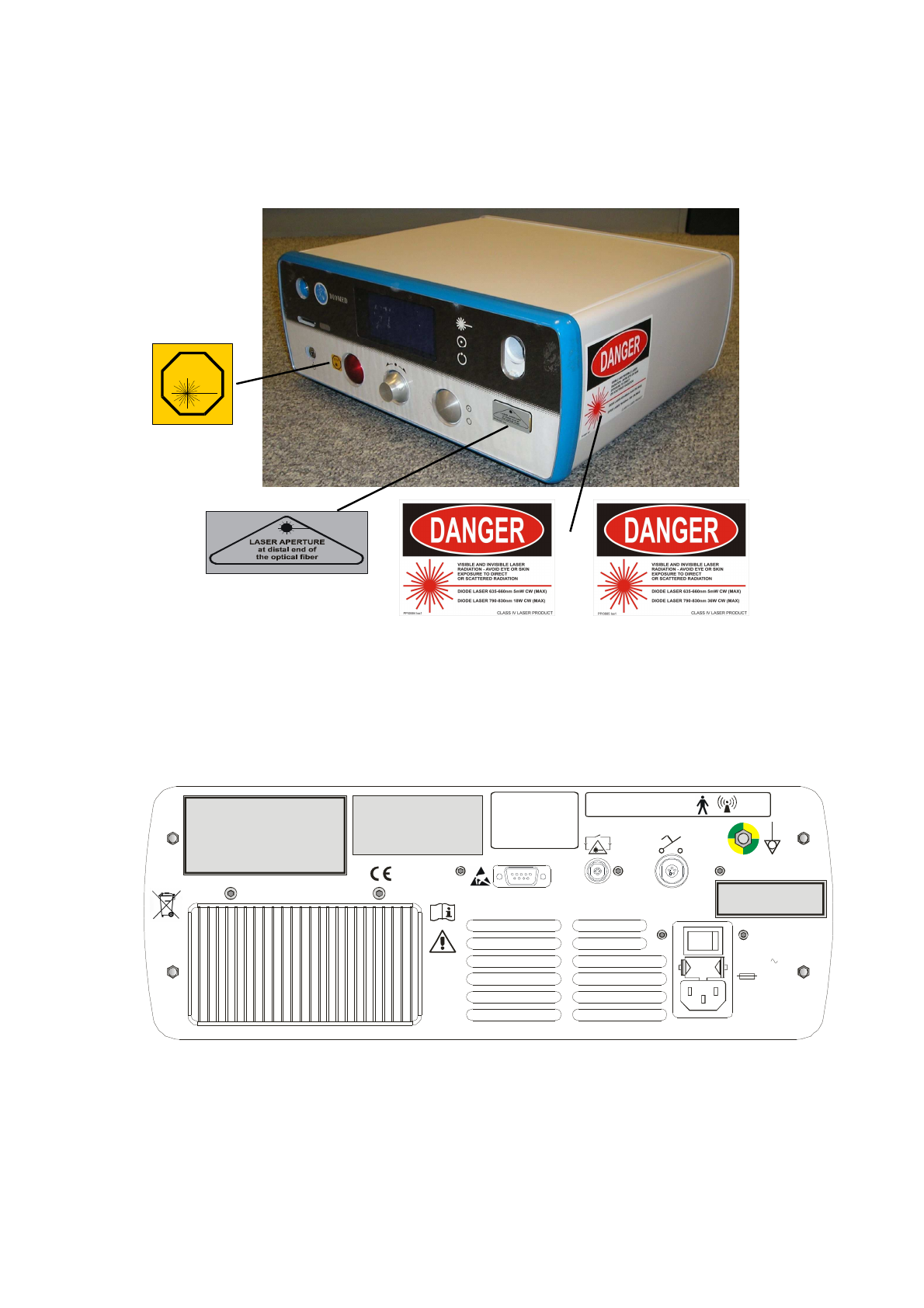
SAFETY LABELLING
Location of Safety Labelling
Safety labels for the DIOMED DELTA 15/30 are positioned as indicated below.
Product Identification Labelling
Product identification labelling is located on the rear of the DIOMED DELTA 15/30.
Diomed Delta Laser
Serial Number: 000000
Date of Manufacture: Sept 2005
100-240V
500VA 50-60Hz
2 x T6.3A
H 250V
0086
IOIOI
Made in the United Kingdom by:
Diomed Ltd.
Building 2000, Beach Drive,
Cambridge Research Park,
Waterbeach,
Cambridge CB5 9TE
Distributed in the USA by
Diomed Inc, MA 01810
This product complies with
21 CFR 1040.10 and 1040.11, UL60601-1,
EN60601-1, 60601-2-22, 60825-1
IP21
This device contains an intentional radiator part number
This product complies with part 15 of the FCC Rules.
Operation is subject to the following two conditions:
(1) This device may not cause harmful interference, and
(2) this device must accept any interference received,
including interference that may cause undesired operation.
This device complies with Canadian RSS-210
AS/0670
FCC ID: RBQAS0670
Canada IC: 4690A-AS0670
GROUNDING RELIABILITY CAN ONLY BE
ACHIEVED WHEN EQUIPMENT IS
CONNECTED TO AN EQUIVALENT
RECEPTACLE MARKED ‘HOSPITAL
ONLY’ OR ‘HOSPITAL GRADE’
PP/1149
STOP
EN 60601-2-22 : 1996
PP/0299 Iss2
DIOMED DELTA 15
Safety Label
DIOMED DELTA 30
Safety Label

DELTA 15/30 Operator Manual Page 2.14 Version B.2
SAFETY FEATURES
The DIOMED DELTA 15/30 includes a number of safety features, which are
provided in accordance with the requirements of the appropriate standards.
• protective housing
• remote interlock bypass
• key switch
• laser radiation emission indicator, visible and audible
• READY and STANDBY modes
• manual reset mechanism
• shutter (not mechanical)
• emergency switch
• location of controls
• safety labels (Figure 1)
• identification and compliance label (Figure 2)
• internal calibration port (optional on DELTA 15)
• calibration procedure for power measurement
• aiming beam
The DIOMED DELTA 15/30 is equipped with the following additional safety
features:
• self test
• laser condition monitoring
• pulse duration monitoring
• power diodes watch-dog
• microprocessor watch-dog
• mains power fail protection
• power supply monitor
• temperature monitors

DELTA 15/30 Operator Manual Page 2.15 Version B.2
EMC DECLARATION
Guidance and manufacturer’s declaration – electromagnetic emissions
The DIOMED DELTA 15/30 is intended for use in the electromagnetic environment specified
below.
The customer or user of the DIOMED DELTA 15/30 should ensure it is used in such an
environment.
Emissions test
Compliance
Electromagnetic emissions – guidance
RF emissions
CISPR 11
Group 1
The DIOMED DELTA 15/30 uses RF energy only for its
internal function. Therefore, its RF emissions are very
low and are not likely to cause any interference in nearby
electronic equipment.
RF emissions
CISPR 11
Class B
Harmonic
emissions
IEC 61000-3-2
Class A
Voltage
fluctuations /
flicker emissions
IEC 61000-3-3
Not
applicable
The DIOMED DELTA 15/30 is suitable for use in all
establishments, including domestic establishments and
those directly connected to the public low-voltage power
supply network that supplies buildings used for domestic
purposes.

DELTA 15/30 Operator Manual Page 2.16 Version B.2
Guidance and manufacturer’s declaration – electromagnetic immunity
The DIOMED DELTA 15/30 is intended for use in an electromagnetic environment specified below.
The customer or the user of the DIOMED DELTA 15/30 should assure that it is used in such an
environment.
Immunity test IEC 60601 test level Compliance level Electromagnetic environment –
guidance
Electrostatic
discharge (ESD)
IEC 61000-4-2
+/- 6 kV contact
+/- 8 kV air
+/- 6 kV contact
+/- 8 kV air
Floors should be wood, concrete or
ceramic tile. If floors are covered with
synthetic material, the relative
humidity should be at least 30%.
Electrical fast
transient / burst
IEC 61000-4-4
+/- 2 kV for power
supply lines
+/- 1 kV for
input/output lines
+/- 2 kV for power
supply lines
+/- 1 kV for
input/output lines
Mains power quality should be that of
a typical commercial or hospital
environment.
Surge
IEC 61000-4-5
+/- 1 kV differential
mode
+/- 2 kV common
mode
+/- 1 kV
differential mode
+/- 2 kV common
mode
Mains power quality should be that of
a typical commercial or hospital
environment.
Voltage Dips, short
interruptions and
voltage variations on
power supply input
lines
IEC 61000-4-11
<5% U
T
(>90% dip in U
T
)
for 0,5 cycle
40 % U
T
(90% dip in U
T
)
for 5 cycles
70 % U
T
(30 % dip in U
T
)
for 25 cycles
<5% U
T
(>95% dip in U
T
)
for 5 sec
<5% U
T
(>90% dip in U
T
)
for 0,5 cycle
40 % U
T
(90% dip in U
T
)
for 5 cycles
70 % U
T
(30 % dip in U
T
)
for 25 cycles
<5% U
T
(>95% dip in U
T
)
for 5 sec
Mains power quality should be that of
a typical commercial or hospital
environment. If the user of the
DIOMED DELTA 15/30 requires
continued operation during mains
interruptions, it is recommended that
the DIOMED DELTA 15/30 be
powered from an uninterruptible
power supply or battery.
Power frequency
(50/60 Hz)
IEC 61000-4-8
3 A/m 3 A/m Power frequency magnetic fields
should be at levels characteristic of a
typical location in a typical
commercial or hospital environment.
NOTE U
T
is the a.c. mains voltage prior to application of the test level.
DELTA 15/30 Operator Manual Page 2.17 Version B.2
Guidance and Manufacturer's declaration – electromagnetic immunity
The DIOMED DELTA 15/30 Laser is intended for use in an electromagnetic environment specified
below. The customer or the user of the DIOMED DELTA 15/30 Laser should assure that it is used in
such an environment.
Immunity test IEC 60601 test level Compliance
level Electromagnetic environment -
guidance
Conducted RF
IEC 61000-4-6
Radiated RF
IEC 61000-4-3
3 Vrms
150 kHz to 80 MHz
3 V/m
80 MHz to 2,5 GHz
3 Vrms
3 V/m
Portable and mobile RF
communications equipment should be
used no closer to any part of the
DIOMED DELTA 15/30, including
cables, than the recommended
separation distance calculated from
the equation applicable to the
frequency of the transmitter.
Recommended separation distance.
d = 1.2 √P
d = 1.2 √P 80MHz to 800 MHz
d = 2.3 √P 800MHz to 2,5 GHz
where P is the maximum output
power rating of the transmitter in
watts (W) according to the transmitter
manufacturer and d is the
recommended separation distance in
metres (m).
Field strengths from fixed RF
transmitters as determined by an
electronic site survey.
a should be less than the
compliance level in each frequency
range.
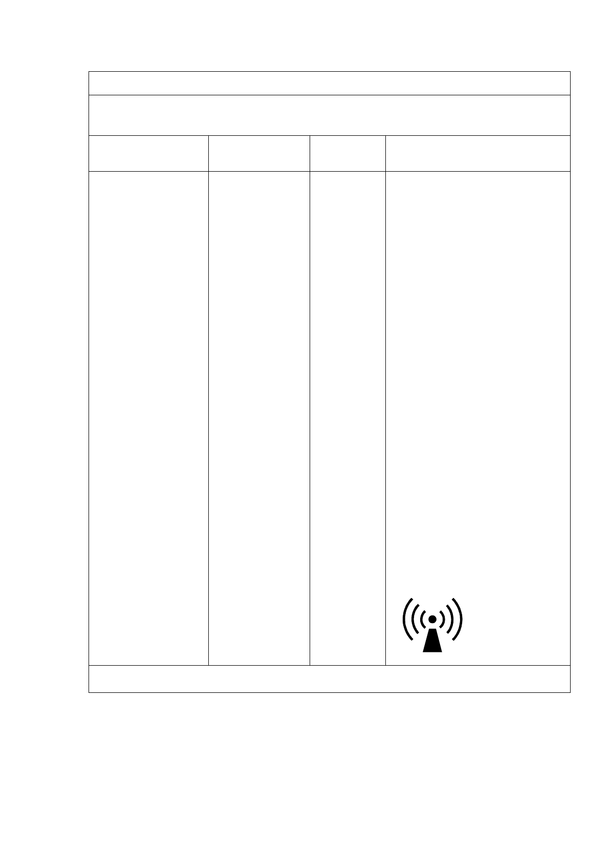
b Interference may occur in the
vicinity of equipment marked with the
following symbol:
NOTE 1 At 80 MHz and 800 MHz, the higher frequency range applies.
NOTE 2 These guidelines may not apply in all situations. Electromagnetic propagation is affected by

DELTA 15/30 Operator Manual Page 2.18 Version B.2
absorption and reflection from structures, objects and people.
a Field strengths from fixed transmitters, such as base stations for radio (cellular/cordless) telephone
and land mobile radios, amateur radio, AM and FM radio broadcast cannot be predicted theoretically
with accuracy. To assess the electromagnetic environment due to fixed RF transmitters, an
electromagnetic site survey should be considered. If the measured field strength in the location in
which the DIOMED DELTA 15/30 is used exceeds the applicable RF compliance level above, the
DIOMED DELTA 15/30 should be observed to verify normal operation. If abnormal performance is
observed, additional measures may be necessary, such as re-orienting or relocating the DIOMED
DELTA 15/30.
b Over the frequency range 150 kHz to 800 MHz, field strengths should be less than 3 V/m.

DELTA 15/30 Operator Manual Page 2.19 Version B.2
Recommended separation distances between portable and mobile RF communications and the
DIOMED DELTA 15/30.
The DIOMED DELTA 15/30 is intended for use in an electromagnetic environment in which
radiated RF disturbances are controlled. The customer or the user of the DIOMED DELTA 15/30
can help prevent electromagnetic interference by maintaining distance between portable and
mobile RF communications equipment (transmitters) and the DIOMED DELTA 15/30 as
recommended below, according to the maximum output power of the communications equipment.
Separation distance according to frequency of transmitter
m
Rated maximum output power of
transmitter
W
150kHz to 80 MHz
d = 1.2 √P
80MHz to 800MHz
d = 1.2 √P
800 MHz to 2,5 GHz
d = 2.3 √P
0.01 0.12 0.12 0.23
0.1 0.38 0.38 0.73
1 1.2 1.2 2.3
10 3.8 3.8 7.3
100 12 12 23
For transmitters rated at a maximum output power not listed above, the recommended separation
distance d in metres (m) can be estimated using the equation applicable to the frequency of the
transmitter, where P is the maximum output power rating of the transmitter in watts (W) according
to the transmitter manufacturer.
NOTE 1 At 80 MHz and 800 MHz, the separation distance for the higher frequency range applies.
NOTE 2 These guidelines may not apply in all situations. Electromagnetic propagation is affected
by absorption and reflection from structures, objects and people.

DELTA 15/30 Operator Manual Page 2.20 Version B.2
ESD PRECAUTIONARY PROCEDURES
ESD (Electrostatic Discharge) occurs in air, causing a spark, when the potential difference between two
bodies exceeds the dielectric strength of the air.
The DIOMED DELTA 15/30 has built-in protection from damage due to ESD, but no protection is 100%
effective and precautions should be taken to protect the DIOMED DELTA 15/30 and any device
connected to it.
When connecting the DIOMED DELTA 15/30 with another device, it is very important for the DIOMED
DELTA 15/30, the device, and you to be at or close to the potential of the earth.
(1) First, momentarily touch a grounded object to remove any existing static charge
(2) Connect one end of the 9-way interface lead to the DIOMED DELTA 15/30, taking care not to
touch the pins of the connector
(3) Connect the other end of the 9-way interface lead to the device, taking care not to touch the
male pins of the associated connector
FCC DECLARATION
This product complies with part 15 of the FCC Rules. Operation is subject to the following two
conditions:
(1) This device may not cause harmful interference, and
(2) This device must accept any interference received, including interference that may cause
undesired operation.
This equipment generates uses and can radiate radio frequency energy and, if not installed and used in
accordance with the instruction manual, may cause harmful interference to radio communications.
Operation of this equipment in a residential area may cause harmful interference in which case the user
will be required to correct the interference at their expense.
Modifications not expressly approved by the manufacturer could void the user’s authority to operate the
equipment under FCC rules.

DELTA 15/30
DELTA 15/30 Operator Manual Page 3.1 Version B.2
SECTION 3 OPERATING INSTRUCTIONS
INTRODUCTION
The DIOMED DELTA 15/30 laser is capable of working with a wide range of fibers and accessories.
The FRS system fitted as standard also allows it to identify the type of fiber or accessory that is
connected. This enables the laser to automatically display suitable preset parameters with the minimum
of user intervention. Therefore the menus and prompts displayed on the screen will vary depending on
the automatically detected settings and it will not be possible to cover every possible scenario in this
operator manual.
Depending on the configuration of the DIOMED DELTA 15/30 some features may be limited or
prohibited. In these situations an explanation will normally be displayed on the screen but, if you have
any doubt, please contact your DIOMED representative for advice.
The following instructions focus on the most common situations, when the DIOMED DELTA 15/30 is
being used with a DIOMED procedure kit, bare fiber or spot handpiece, fitted with the FRS system.
CONTENTS
Section 3
OPERATING INSTRUCTIONS ............................................................................................ 1
Introduction............................................................................................................................................. 1
Contents ................................................................................................................................................. 1
Conventions............................................................................................................................................ 2
Summary ................................................................................................................................................ 2
Installation and set-up ............................................................................................................................ 4
Front Panel Controls............................................................................................................................... 6
Rear Panel Controls ............................................................................................................................... 8
Fiber Recognition System ...................................................................................................................... 9
Operating Instructions .......................................................................................................................... 11
Spot Handpiece Mode.......................................................................................................................... 16
Manual Operation ................................................................................................................................. 20
Session Fault Emergency Override...................................................................................................... 23
Set-up Menu ......................................................................................................................................... 24
Session Statistics ................................................................................................................................. 27
Symbols used on Diomed products...................................................................................................... 28

DELTA 15/30
DELTA 15/30 Operator Manual Page 3.2 Version B.2
CONVENTIONS
The following naming conventions are used throughout these Operating Instructions
Controls on the front panel are expressed in bold capitals. SCROLL, STANDBY
Functional modes of the DIOMED DELTA 15/30 are expressed in capitals. STANDBY, READY
Menu items are expressed in bold mixed case. Main Menu, Language
SUMMARY
1. Place the DIOMED DELTA 15/30 in a convenient position on an
instrument table no farther than 1.8 metres from the patient. Ensure that
all controls are within easy reach of the operator.
2. Ensure that the ventilation holes in the base and rear of the DIOMED
DELTA 15/30 are not obstructed.
3. Connect the electrical power cord to the main power outlet.
4. Connect the footswitch and place in a convenient position for the
operator.
5. Insert either a remote interlock bypass or, if required, connect the door
interlock cable to the remote interlock socket on the rear of the DIOMED
DELTA 15/30.
6. Check that approved safety glasses are available and laser-warning
signs are provided at entrances to the treatment room.
All personnel present must wear approved safety glasses. DIOMED
recommends that the patient’s eyes are taped shut if the patient is
unconscious.
7. Connect the optical fiber or Spot Handpiece to the laser aperture,
ensuring that the connector is screwed ‘finger tight’.
8. Turn on the rear power switch and key switch to activate the DIOMED
DELTA 15/30. While the self-test is running, check that the front panel
indicators light up and the audible indicator sounds momentarily.
9. After the self-test, use the SCROLL/CONFIRM control to select the
required procedure.
10. If required, follow the on-screen instructions to calibrate the fiber or Spot
Handpiece.

DELTA 15/30
DELTA 15/30 Operator Manual Page 3.3 Version B.2
TO ENSURE BEST PERFORMANCE AND EFFICACY, ALWAYS USE
DIOMED FIBERS, PROCEDURE KITS AND ACCESSORIES.
ONLY 600µ
µµ
µm NON-CONTACT FIBERS WITH A COOLING SHEATH CAN BE
CALIBRATED.
CONTACT FIBERS DO NOT REQUIRE CALIBRATING.
THE DISPLAYED POWER WITH A CONTACT FIBER OR UNCALIBRATED
NON-CONTACT FIBER IS THE POWER LEVEL AT THE LASER APERTURE.
IT SHOULD BE ASSUMED THAT THE POWER LEVEL AT TISSUE IS 10-15%
LOWER.
11. The system will automatically go to the STANDBY mode, with a set of
default operating parameters. If required, adjust these parameters now
using the SCROLL/CONFIRM control. The DIOMED DELTA 15/30 is
now ready to begin the treatment.
12. To start treatment and delivery of laser energy, press
STANDBY/READY, wait for the DIOMED DELTA 15/30 to enter READY
mode and depress the footswitch. During laser radiation the laser
emission indicator will light and an audible warning will be heard.
13. To pause treatment, release the footswitch. To continue treatment, press
the footswitch. To end treatment, release the footswitch and return the
unit to STANDBY.
14. A summary of laser energy delivered may be reviewed if required by
selecting Statistics from the Main Menu.
15. To turn the DIOMED DELTA 15/30 OFF turn the key switch and remove
the key, then switch off the rear power switch.
If an error message is displayed, refer to section 5 - Technical Information.
DELTA 15/30
DELTA 15/30 Operator Manual Page 3.4 Version B.2
INSTALLATION AND SET-UP
Installation of the DIOMED DELTA 15/30 can be carried out by the end-user.
Inspection
Inspect the DIOMED DELTA 15/30 and contents for signs of damage. If the unit is damaged DO NOT
USE - contact DIOMED or your local DIOMED representative. If there are no signs of damage and all
components are present, assemble the DIOMED DELTA 15/30.
Check that the following components are included in the packaging
DIOMED DELTA 15/30 Laser unit
• Footswitch
• IEC Power cable
• 2 x Remote Interlock bypass connectors
• 2 x Keys
• 4 x T6.3A fuses
• Operator Manual
The DIOMED DELTA 15/30 will operate at mains voltages between 100 V and 240 V AC without
adjustment.
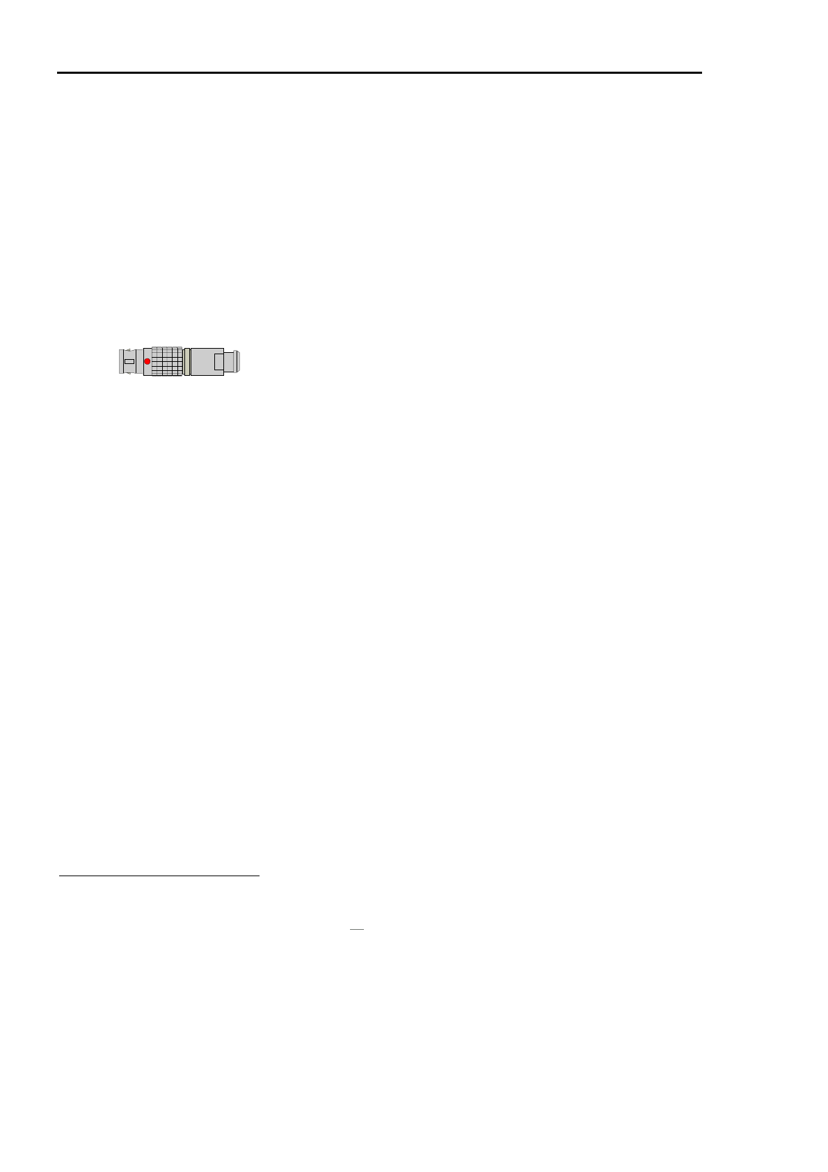
1. Connect the footswitch to the footswitch socket (line up red dots and insert).
2. Connect a remote interlock bypass connector to the remote interlock socket (line up red dots
and insert).
3. Connect the optical fiber or Spot Handpiece
1
to the laser aperture as described in the section
below.
4. Insert the IEC Power cord into the power inlet socket and connect to the main power supply.
5. Switch the power switch to ON ( | ).
6. Insert a key into the key switch on the front of the unit.
7. The DIOMED DELTA 15/30 is now installed and ready for use.
Connecting to the Laser Aperture
Laser energy is delivered to the optical fiber or spot handpiece via the laser aperture located on the
front panel of the DIOMED DELTA 15/30. The fiber or handpiece is connected by means of an SMA-
905 type optical fiber connector.
To insert the optical fiber connector, first remove the protective cap from the end of the fiber. Then press
down on the tab of the spring-loaded dust cover, insert the optical fiber connector into the laser aperture
on the DIOMED DELTA 15/30 and turn the gripper clockwise until secured in place (light finger tight
only).
1
A Spot Handpiece can only be used with a DIOMED DELTA 15/30 laser fitted with an optical power
calibration port. The Ø 2mm Spot Handpiece can be used with either laser but the Ø 4mm Spot
Handpiece may only be used with the DIOMED DELTA 30.

DELTA 15/30
DELTA 15/30 Operator Manual Page 3.5 Version B.2
It is essential that the exposed end of the optical fiber be kept clean to prevent
damage to the DIOMED DELTA 15/30 and optical fiber.
To remove the optical fiber connector, turn the gripper anti-clockwise until fully unscrewed and
disconnect from the laser aperture. Dispose of the optical fiber according to institution policy.
Alternatively, if the optical fiber is permitted for multiple uses, immediately fit a protective cap over the
end of the optical fiber to protect the optical surface from contamination.
DELTA 15/30
DELTA 15/30 Operator Manual Page 3.6 Version B.2
FRONT PANEL CONTROLS
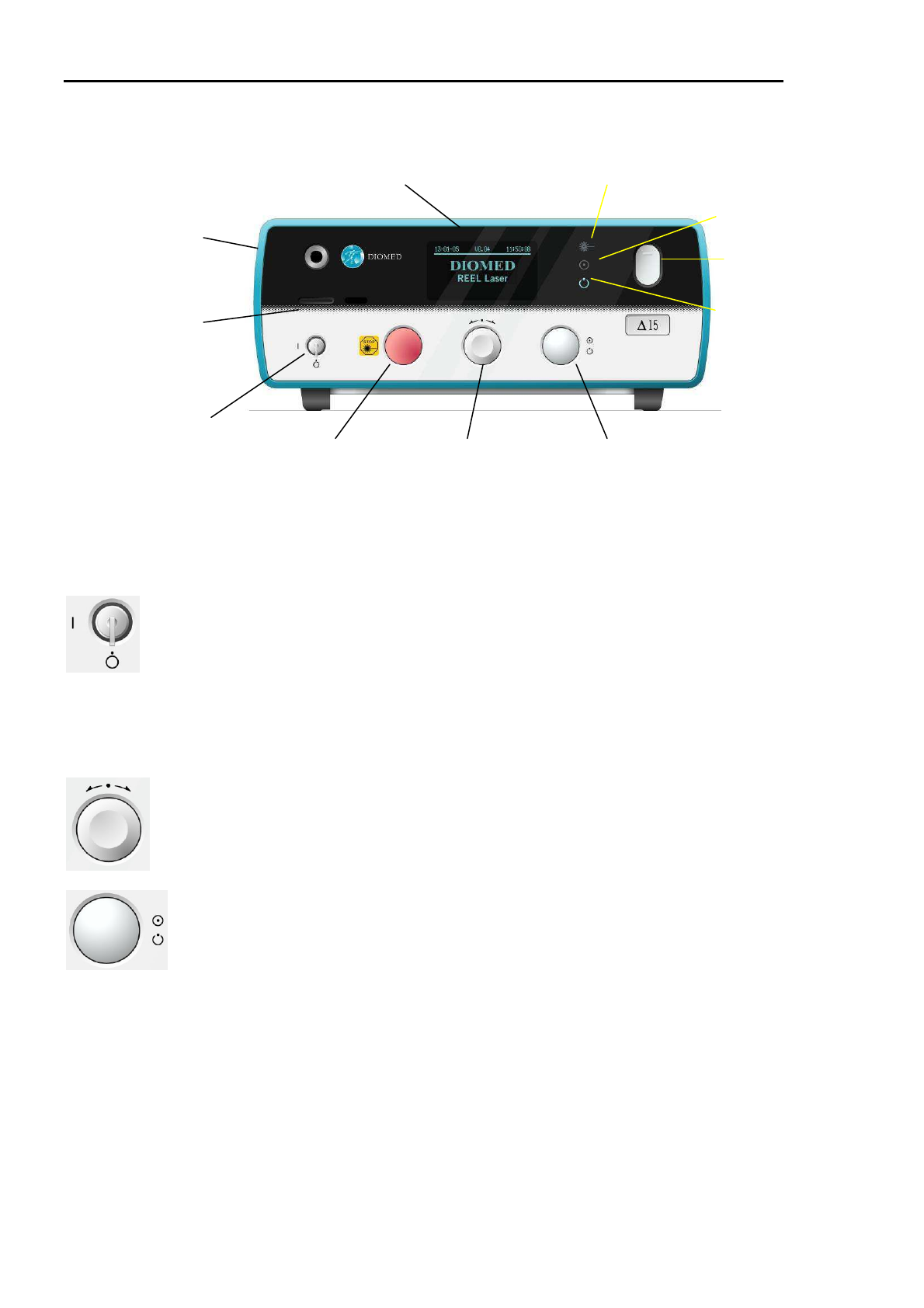
The main operating controls for the DIOMED DELTA 15/30 are located on the lower section of the front
panel. The display and other indicators are located in the top section of the panel, as illustrated in the
figure above.
Key Switch
The key switch is used to start the DIOMED DELTA 15/30 and is the main
control for the device. The key is removable only in the OFF position and the
laser is not operable when the key is removed.
DIOMED recommends that the keys are assigned to one or two key-holders,
who should keep the keys in a secure place and make them available for
scheduled procedures only, thus preventing unauthorised use of the system.
DIOMED also recommends that the key is not mixed with other keys on the
same ring.
Display Screen This displays all menu options and information.
Scroll / Confirm
To enable selection of Menu commands. Turn the knob left or right to move
between commands and press the knob to confirm the selection.
Standby / Ready
To select STANDBY or READY mode. Laser energy delivery is possible only
in the READY mode. When the READY request is made, the READY light
flashes for two seconds before the system enters READY mode. Pressing the
button a second time will return the system to STANDBY mode.
If the footswitch is pressed when a READY request is made or during the
flashing of the READY light, the message ‘Footswitch held down’ is displayed
and the footswitch should be released before the operation can continue. The
message will disappear when the footswitch is released.
Standby Indicator This light will be on when the laser is in STANDBY mode.
Display
Ready Indicator
Scroll/Confirm
Standby Indicator
Standby/Ready
Key Switch Laser Aperture
Emergency Stop
Calibration Port
(if fitted)
Laser Emission Indicator
Memory Card Slot
Key Switch

DELTA 15/30
DELTA 15/30 Operator Manual Page 3.7 Version B.2
Ready Indicator
This light will be on when the laser is in READY mode.
Laser Emission
Indicator
When laser energy is being delivered to the output port, this light will be on.
Emergency Switch
To shut down the laser immediately in case of emergency, press the red button
located on the front panel of the main enclosure. After activation of the
emergency switch, the key switch must be used to restart the system.
Laser Aperture Laser energy is delivered to the optical fiber or handpiece via the laser
aperture located on the front panel. Slide the cover down to access the
aperture.
Use only DIOMED approved or DIOMED labelled optical fibers. Damage
caused by use of unapproved handpieces or fibers may invalidate the
guarantee.
Calibration Port A calibration port is provided on the front panel of some models. This can be
used, with the appropriate adaptor, to calibrate a fixed focus spot handpiece or
an optical fiber.
DELTA 15/30
DELTA 15/30 Operator Manual Page 3.8 Version B.2
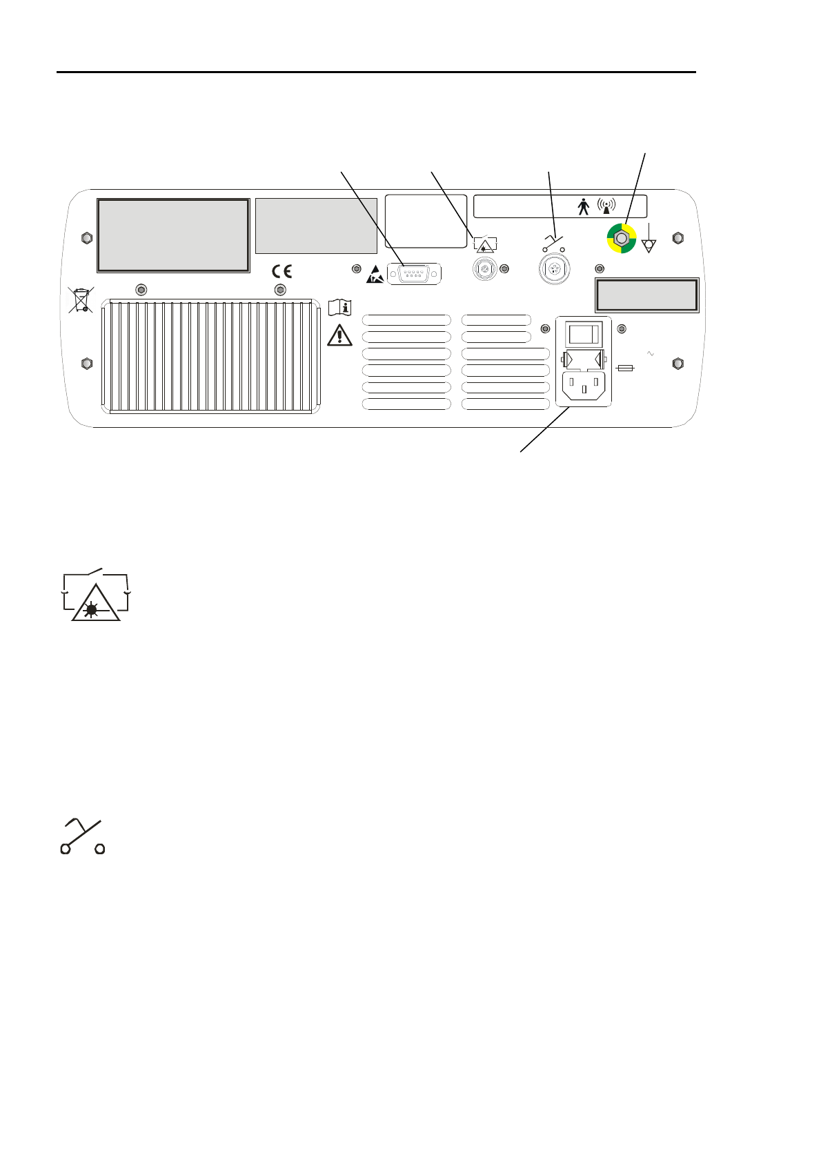
Power Inlet Socket,
Switch & Fuseholder
Remote Interlock
Footswitch Socket
Potential Equalisation Point
Serial Port
REAR PANEL CONTROLS
Power Inlet Socket To connect an IEC power cord.
Power Switch To switch the main power to the system on or off.
Remote Interlock
Socket
To connect the remote interlock cable connector. This will automatically
switch the system to STANDBY mode in the event of the door being opened
during the procedure.
If the remote interlock is connected to a door switch, then the cable used
should be shielded and the shield connected to the plug body. An EMC sleeve
(ferrite tube) should also be fitted over the cable adjacent to the connector.
DIOMED can supply these on request. These precautions will ensure that the
possibility of electromagnetic emissions is minimised.
DIOMED supplies two remote interlock bypasses for facilities without or not
wishing to use the door switch option. The DIOMED DELTA 15/30 will not
operate without the remote interlock bypass being inserted into the remote
interlock socket on the rear of the laser.
Footswitch Socket
To connect the footswitch to the DIOMED DELTA 15/30.
Serial Port
IOIOI
This connection is normally only used for diagnostic purposes by authorised
DIOMED personnel.
Potential To connect a potential equalisation line, for common grounding between
Diomed Delta Laser
Serial Number: 000000
Date of Manufacture: Sept 2005
100-240V
500VA 50-60Hz
2 x T6.3A
H 250V
0086
IOIOI
Made in the United Kingdom by:
Diomed Ltd.
Building 2000, Beach Drive,
Cambridge Research Park,
Waterbeach,
Cambridge CB5 9TE
Distributed in the USA by
Diomed Inc, MA 01810
This product complies with
21 CFR 1040.10 and 1040.11, UL60601-1,
EN60601-1, 60601-2-22, 60825-1
IP21
This device contains an intentional radiator part number
This product complies with part 15 of the FCC Rules.
Operation is subject to the following two conditions:
(1) This device may not cause harmful interference, and
(2) this device must accept any interference received,
including interference that may cause undesired operation.
This device complies with Canadian RSS-210
AS/0670
FCC ID: RBQAS0670
Canada IC: 4690A-AS0670
GROUNDING RELIABILITY CAN ONLY BE
ACHIEVED WHEN EQUIPMENT IS
CONNECTED TO AN EQUIVALENT
RECEPTACLE MARKED ‘HOSPITAL
ONLY’ OR ‘HOSPITAL GRADE’
PP/1149

DELTA 15/30
DELTA 15/30 Operator Manual Page 3.9 Version B.2
Equalisation Point
equipment(s), if needed.
Fuseholder
2 x T6.3A H 250V
Use of controls or adjustments, and or performance of
procedures other than those specified herein may result
in hazardous radiation exposure.
FIBER RECOGNITION SYSTEM
What is the Fiber Recognition System (FRS)?
All DIOMED DELTA 15/30 lasers are equipped with the DIOMED Fiber Recognition System (FRS). This
system provides a means of identifying the fiber that is connected to a DIOMED DELTA 15/30.
DIOMED fibers are normally supplied in a kit of components for a particular procedure. Therefore, by
identifying the fiber, the laser can also tell what procedure is going to be performed. So the DIOMED
DELTA 15/30 can automatically select suitable preset parameters with the optimum values for that
procedure. Compared to setting the parameters manually, this process is much quicker and far less
prone to user error.
Some versions of the DIOMED DELTA 15/30 can also operate with non-DIOMED fibers, as long as
they are fitted with a DIOMED adapter at the laser end of the fiber. This adapter is available as an
accessory from your DIOMED representative and it will allow the DIOMED DELTA 15/30 to be used in
Manual mode only.
How does FRS work?
A miniature Radio Frequency Identification (RFID) device is located inside the gripper at the end of the
fiber connected to the laser. This is read by a receiver inside the DIOMED DELTA 15/30 whenever it is
switched on and a fiber connected to it. The RFID device contains a memory chip that holds the
following information:
The type of fiber This tells the system what type of fiber or accessory has been
connected to it.
2
The date when the sterility of
the fiber expires
If the sterility expiration date is earlier than the current date in
the internal clock of the DIOMED DELTA 15/30 then the fiber
is invalid and cannot be used.
How many times the fiber
may be safely used
The number of “uses”
3
is decreased each time the system is
used with the connected fiber. When the figure reaches zero,
the fiber becomes invalid and cannot be used again.
2
The system will read the fiber’s data if the power is on and a FRS fiber is connected or if the DIOMED
DELTA 15/30 is powered up with a FRS fiber already connected.

DELTA 15/30
DELTA 15/30 Operator Manual Page 3.10 Version B.2
What are the benefits of FRS?
• Single-use fibers cannot be re-used, as sterility and optical performance cannot be assured.
• Fibers that have passed their sterility expiration date cannot be used, minimizing the risk of
patient infection.
• The number of available “uses”, subject to satisfactory calibration, for Multiple-use and Spot
Handpiece fibers is displayed on the screen, giving a clear indication of when a fiber is due for
replacement.
• Operation of the DIOMED DELTA 15/30 is simplified, because the FRS is able to automatically
recognize devices independently of the user – for example, the type of Spot Handpiece.
In order to obtain full advantage of DIOMED FRS you should always use fibers supplied by DIOMED or
fibersdirect.com. Please contact your DIOMED representative for a list of fibers and procedure kits that
are compatible with the FRS system.
3
The number of available “uses” is only decreased once per procedure and only after the DIOMED
DELTA 15/30 has been fired. Subsequent firing of the DIOMED DELTA 15/30 during a continuous
procedure will not result in the number of available “uses” being further decreased.
DELTA 15/30
DELTA 15/30 Operator Manual Page 3.11 Version B.2
OPERATING INSTRUCTIONS
Once the DIOMED DELTA 15/30 has been correctly installed and switched on, it is operated using just
two controls:
SCROLL / CONFIRM Turn the knob in either direction to SCROLL through the available options
highlighted on the screen.
Press the knob to CONFIRM the selection.
STANDBY / READY Once the DIOMED DELTA 15/30 is set up and ready for the procedure, press
this button to switch between the STANDBY and READY modes.
Laser energy delivery is possible only in the READY mode.
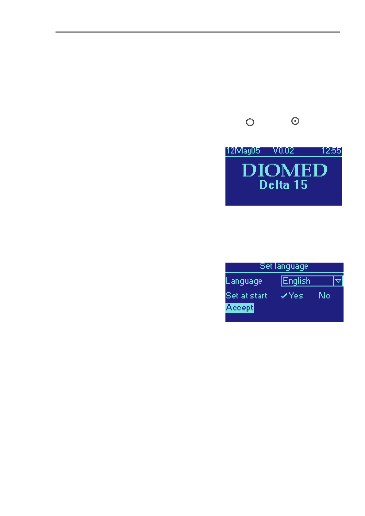
Switching On
Ensure that the DIOMED DELTA 15/30 has been set up
correctly, as described above and that the remote interlock,
footswitch and fiber connectors are all in place. Switch on
the rear panel power switch. The display will show a screen
similar to the one on the right.
Turn the key switch clockwise to activate the system. It will
now perform a self-test function for a few seconds. While
this is running, ensure that the indicators for Laser
Emission, Standby and Ready are all illuminated and that
the audible indicator sounds briefly.
Setting the language at switch-on
The system will now prompt for the language to be used by
the user interface. If you wish to change it, turn the
SCROLL knob until Language is highlighted and press to
CONFIRM. You can now use the SCROLL knob to select
the required language from the drop down list. Press again
to CONFIRM the selection.
When Set at start is set to Yes, this screen will occur every
time that the DIOMED DELTA 15/30 is switched on. To
prevent this, change the selection to No as follows:
• Turn the SCROLL knob until Set at start is
highlighted.
• Press CONFIRM to toggle between Yes and No.
• Turn the SCROLL knob to select Accept.
• Press CONFIRM.
You will still be able to change the language setting from
the Setup menu option on the Main menu.
DELTA 15/30
DELTA 15/30 Operator Manual Page 3.12 Version B.2
Interlock Checks
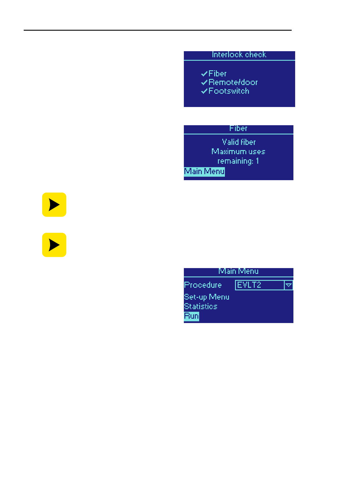
The system will now check that all the safety interlocks are
properly in place. If a tick is not shown against one or more
of the items in the display, recheck the appropriate
connection.
Fiber Identification & Validation
After it has finished checking the interlocks, the DIOMED
DELTA 15/30 system reads the FRS information stored
inside the fiber’s gripper. It will check the type of fiber, how
many “uses” are available and whether it is within its sterility
expiration date. This information will be displayed on the
screen for a few seconds.
If the DIOMED DELTA 15/30 does not detect the presence of a valid DIOMED
FRS
fiber or adapter then it will not permit a procedure to be carried out.
An error message will be displayed on the screen – see Troubleshooting in the
Technical Information section.
An Emergency Override option is included to allow the DIOMED DELTA 15/30
to be used once only in the event of a session fault, which has prevented the
completion of a treatment. See Session Fault Emergency Override below for
instructions on how to use this option.
Once the fiber is validated, the DIOMED DELTA 15/30 is
able to determine which procedures may be performed and
can set itself up with the appropriate parameter values for
power, pulse duration and interval. Depending on the type of
fiber connected, a screen similar to the following will be
displayed.
Procedure Selection
DELTA 15/30
DELTA 15/30 Operator Manual Page 3.13 Version B.2
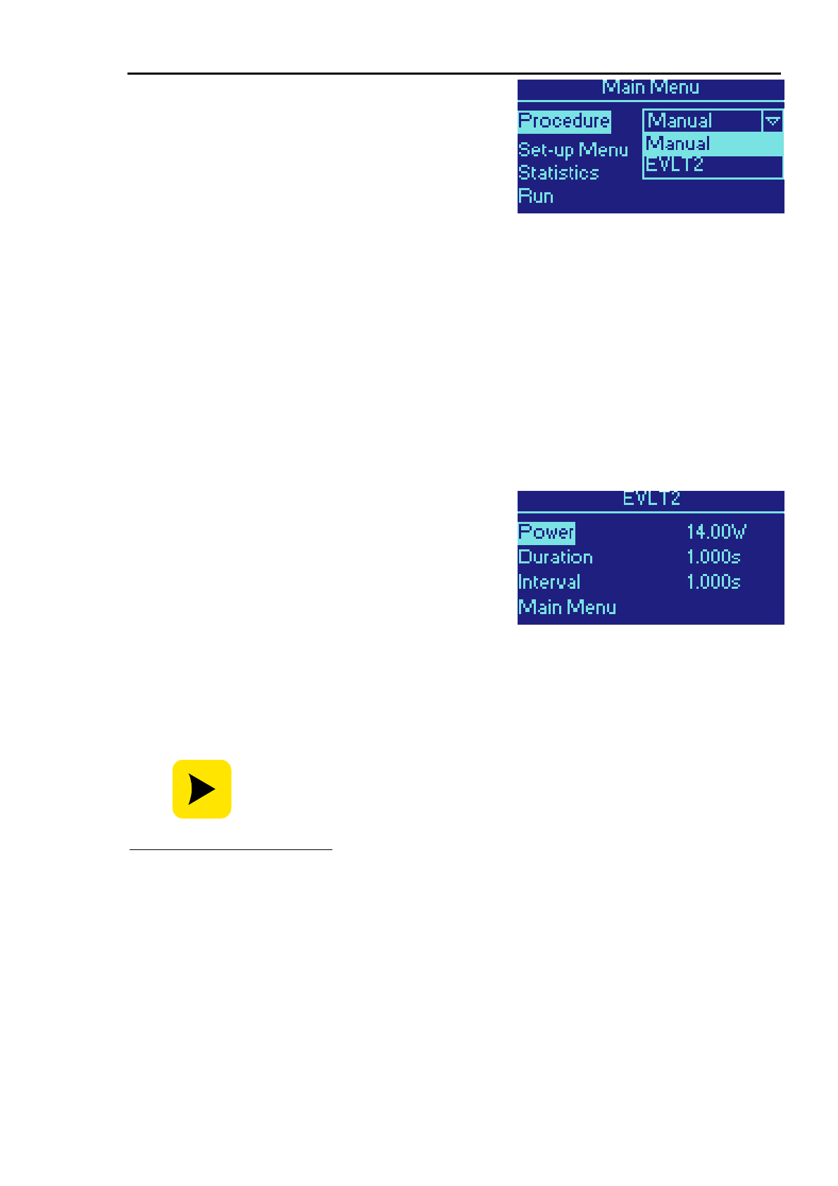
In the following example, a fiber from a DIOMED EVLT
procedure kit has been connected to the laser. The DIOMED
DELTA 15/30 recognises this fiber and loads a list of
compatible procedures into the top, as shown on the
display
4
.
The default procedure is shown at the top of the menu. To
select a different procedure turn the SCROLL knob until
Procedure is highlighted and press CONFIRM. Select the
desired procedure with the SCROLL knob and press
CONFIRM again.
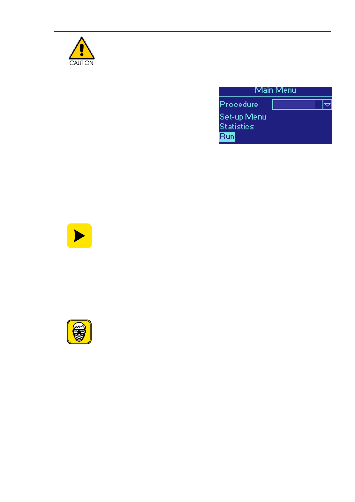
When the procedure has been selected, highlight Run using
the SCROLL knob and press CONFIRM.
Parameter Adjustment
At this point, calibration may be required for certain fibers and procedures. In this case, follow the
instructions on page 14.
The DIOMED DELTA 15/30 will set the default operating parameters for the selected procedure. Some
procedures also allow the default parameters to be varied within lower and upper limits, which are
defined in the procedure’s specification.
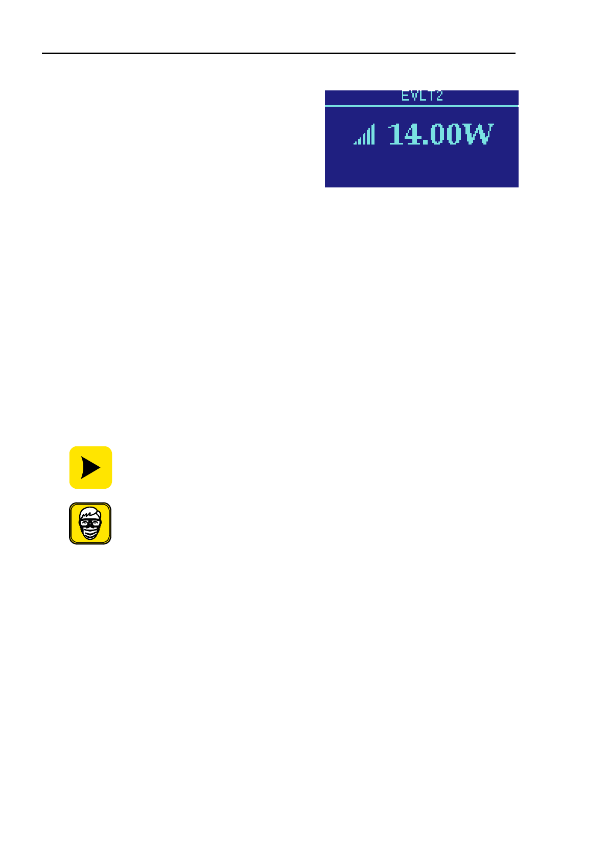
To adjust a parameter, turn the SCROLL knob to highlight
the required parameter (Power, Pulse or Interval) and
press CONFIRM. The highlight will now move to the value
of the parameter on the right hand side of the display. Turn
the SCROLL knob to adjust the value and press CONFIRM
again. The highlight will move back to the left hand side of
the display. Repeat this process for the other parameters
as required.
When you have completed setting up the operating
parameters of the DIOMED DELTA 15/30, turn the
SCROLL knob to move the highlight to Continue and press
CONFIRM.
The method of adjusting settings will vary depending on the procedure selected.
Please refer to section 4 entitled DIOMED Procedures for full details of how to
use specific procedures.
4
The list of procedures shown on this menu will only include those that are installed in the laser.
DIOMED will, over the lifetime of this system, release new procedures that may be compatible with
currently available fibers. Please check with your DIOMED representative for the latest information
regarding available procedures. Further information on the currently available procedures and the
methods of installing them into the DIOMED DELTA 15/30 can be found in section 4.
DELTA 15/30
DELTA 15/30 Operator Manual Page 3.14 Version B.2
Run the Procedure
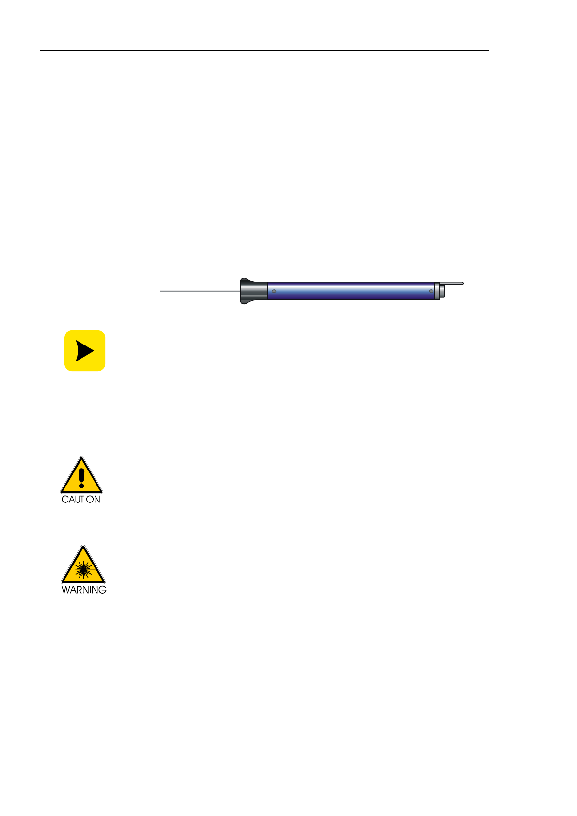
The DIOMED DELTA 15/30 is now ready to start the
procedure. Press STANDBY/READY and wait for the
DIOMED DELTA 15/30 to enter the READY mode.
Depress the footswitch. An audible warning will be heard
during laser irradiation and the laser emission indicator will
be lit.
To pause treatment, release the footswitch. Press the
footswitch again to continue. To end treatment, release the
footswitch and return the unit to STANDBY.
Note: the DIOMED DELTA 15/30 will automatically return
to STANDBY if treatment is paused for 3 minutes.
To turn the DIOMED DELTA 15/30 off, turn the key switch
anti-clockwise, remove the key and switch off at the rear
panel.
Calibration
Calibration is not a requirement for all procedures. However, if necessary, calibration is normally
performed after the procedure has been selected. If appropriate, calibration can also be performed by
selecting the Calibration option at the main menu screen.
This feature is not available on the DIOMED DELTA 15 unless fitted with the optional Optical Power
Calibration Port.
This calibration procedure is for 600µm non-contact fibers with a cooling sheath
only. Contact fibers cannot be calibrated.
Ensure all personnel are wearing approved safety eyewear.
When calibration is carried out, the displayed power will be the power at the distal
end of the fiber.
If calibration is NOT carried out, the displayed power will be the power at the laser
aperture.
Instructions on how to perform the calibration routine are displayed on the screen. Selecting Cancel at
any time will return the user to the Main Menu leaving the fiber un-calibrated.
1. Screw in the optical fiber calibration port adapter. (The adapter should be sterilised in order to
maintain fiber sterility).

DELTA 15/30
DELTA 15/30 Operator Manual Page 3.15 Version B.2
2. Guide the fiber into the calibration port using the optical fiber calibration port adapter provided.
3. Place the DIOMED DELTA 15/30 in READY mode.
4. Follow the instructions on screen.
5. Fire the DIOMED DELTA 15/30 by pressing the footswitch until release is indicated on the
display.
6. The screen will display the fiber acceptability and transmission percentage.
7. To proceed, highlight Continue and press SELECT.
Transmission Acceptability
The DIOMED DELTA 15/30 will calculate the percentage transmission of the fiber system, and the
results will be shown on screen as Acceptable or Unacceptable.
• A percentage rating of 75% - 100% indicates that the fiber is Acceptable, and ‘Cal’ is displayed
in the top right corner of the display showing that the fiber has been calibrated. The power
displayed will represent the power output at the distal end of the calibrated fiber and the system
will compensate for any fiber transmission losses.
• A percentage rating of 0% - 75% indicates that the fiber is Unacceptable. In this case the fiber
must be replaced with a new fiber and re-calibrated.
Calibration will be cancelled if:
• The unit is turned off or
• The fiber port interlock is activated (i.e. the user has changed the fiber).
DELTA 15/30
DELTA 15/30 Operator Manual Page 3.16 Version B.2
SPOT HANDPIECE MODE
This section includes special instructions to be followed when using a spot handpiece with the DIOMED
DELTA 15/30.
Spot Handpiece mode is only available when the DIOMED DELTA 15/30 is fitted with a calibration port.
This port is optional on the DIOMED DELTA 15.
Fixed Focus Spot Handpiece
The handpiece delivery system consists of a sleeved optical fiber, with an optical
fiber connector at one end and a handpiece at the other. The handpiece has a
user replaceable protective lens.
A Ø 2mm fixed focus Spot Handpiece is available separately for use with the
DIOMED DELTA 15/30. The Ø 2mm fixed focus Spot Handpiece, colour-coded
blue for identification, delivers a 2mm diameter beam of laser energy.
Ø 2mm fixed focus Spot Handpiece
A Ø 4mm fixed focus Spot Handpiece (not illustrated) is available separately for
use with the DIOMED DELTA 30 only. The Ø 4mm fixed focus Spot Handpiece is
colour-coded yellow for identification and delivers a 4mm diameter beam of laser
energy.
New handpieces are supplied with the fiber fitted and with an integrated FRS
gripper. If you have an older Spot Handpiece, without a FRS gripper, please
contact your local DIOMED representative who will be able to supply you with a
new fiber.
Great care must be taken in ensuring optical faces are kept clean, particularly at
the optical fiber connector end. A protective cap is provided which should be
replaced each time the optical fiber end of the fiber is not connected to the Laser
aperture.
Before using the handpiece inspect the fiber and connector for signs of damage
and check the handpiece to ensure it is clean, correctly assembled and has no
signs of damage.
If there is any evidence of handpiece damage or fiber breakage do not use
the handpiece as it may cause injury to the operator or patient. Replace the
handpiece or fiber immediately. (See fixed focus Spot Handpiece
Instructions for Use if the fiber requires changing).
DELTA 15/30
DELTA 15/30 Operator Manual Page 3.17 Version B.2
The Ø 2mm fixed focus Spot Handpiece delivers power densities four times
greater than the Ø 4mm fixed focus Spot Handpiece at the same
power/duration settings.
Handpiece Identification
After it has finished checking the interlocks, the system will
read the FRS information stored inside the handpiece’s
gripper. From this the laser is able to determine whether it is
a Ø 2mm or Ø 4mm handpiece. Depending on the type of
handpiece connected, a screen similar to the following will
be displayed.
If the laser does not detect the presence of a valid FRS Spot
Handpiece then it will not permit a procedure to be carried
out. Please refer to the Troubleshooting section for help in
this situation.
Calibration
Calibration of a Spot Handpiece must be performed either each time the unit is
switched ON or each time a new handpiece is connected. This ensures that
accurate Fluence is available at the treatment site.
The DIOMED DELTA 15/30 system will always perform a calibration if the
handpiece has not been calibrated.
The Spot Handpiece will require re-calibration if any of the following occur during
the treatment session:
• Power failure / unit switched off
• Footswitch disconnected
• Emergency switch pressed
• Handpiece is disconnected
• A new handpiece is used
Ensure all personnel are wearing approved safety glasses.
Ensure that the window cell / treatment window of the handpiece to be
calibrated is clean.
Instructions on how to perform the calibration routine are displayed on the screen. Selecting Cancel at
any time will return the user to the Main Menu leaving the Spot Handpiece un-calibrated.
1. Screw in the Spot Handpiece calibration port adapter.
2. Insert the Spot Handpiece into the calibration port adapter.
2mm spot

DELTA 15/30
DELTA 15/30 Operator Manual Page 3.18 Version B.2
3. Ensure that the probe on the Spot Handpiece lines up with the hole on the adapter and is
inserted fully into the calibration port.
4. Place the DIOMED DELTA 15/30 in READY mode.
5. Follow the instructions on screen.
6. Fire the DIOMED DELTA 15/30 by pressing the footswitch until release is indicated on the
display.
7. The screen will display the handpiece acceptability and transmission percentage.
8. To proceed, highlight Continue and press SELECT.
Transmission Acceptability
The DIOMED DELTA 15/30 will calculate the percentage transmission of the handpiece system, and
the results will be shown on screen as Acceptable or Unacceptable.
Transmission should be 65% or greater. If less than 65% the result will be shown as Unacceptable and
the handpiece will need cleaning or replacing if damaged (see Fixed Focus Spot Handpiece Instructions
for Use supplied with the handpiece).
After carrying out the calibration procedure the DIOMED DELTA 15/30 will display that the handpiece
has been calibrated.
Fluence
After successful calibration of a Spot Handpiece, the Fluence screen will be displayed.
The Fluence function automatically calculates and displays the laser energy per unit area (J/cm
2
)
projected onto the patient. If the Power and Pulse duration are adjusted, the Fluence will be
automatically re-calculated and the display updated.
Fluence (J/cm
2
) is calculated using the formula:
where Spot Radius = 0.1 cm for a Ø 2 mm spot handpiece.
To adjust a parameter, turn the SCROLL knob to highlight
the required parameter (Power, Pulse or Interval) and
press CONFIRM. The highlight will now move to the value
of the parameter on the right hand side of the display. Turn
the SCROLL knob to adjust the value and press CONFIRM
again. The highlight will move back to the left hand side of
the display. Repeat this process for the other parameters
as required.
When you have set up the required value of fluence of the
DIOMED DELTA 15/30, turn the SCROLL knob to move
the highlight to Continue and press CONFIRM.
)()(
)()(
2
cmRadiusSpotx
sDurationPulsexWPower
Fluence
π
=

DELTA 15/30
DELTA 15/30 Operator Manual Page 3.19 Version B.2
The DIOMED DELTA 15/30 is now ready to start the
procedure. Press STANDBY/READY and wait for the
DIOMED DELTA 15/30 to enter the READY mode.
Depress the footswitch. An audible warning will be heard
during laser irradiation and the laser emission indicator will
be lit.
To pause treatment, release the footswitch. Press the
footswitch again to continue. To end treatment, release the
footswitch and return the unit to STANDBY.
Note: the DIOMED DELTA 15/30 will automatically return
to STANDBY if treatment is paused for 3 minutes.
To turn the DIOMED DELTA 15/30 off, turn the key switch
anti-clockwise, remove the key and switch off at the rear
panel.

DELTA 15/30
DELTA 15/30 Operator Manual Page 3.20 Version B.2
MANUAL OPERATION
Manual operation is not enabled on all versions of the DIOMED DELTA 15/30. Please consult with your
DIOMED representative if you require assistance with setting up your laser.
For best results always use the DIOMED DELTA 15/30 with a DIOMED FRS fiber. This will be detected
by the laser, which will automatically select suitable preset parameters. However it is also possible to
manually configure the settings DIOMED DELTA 15/30 in the following situations:
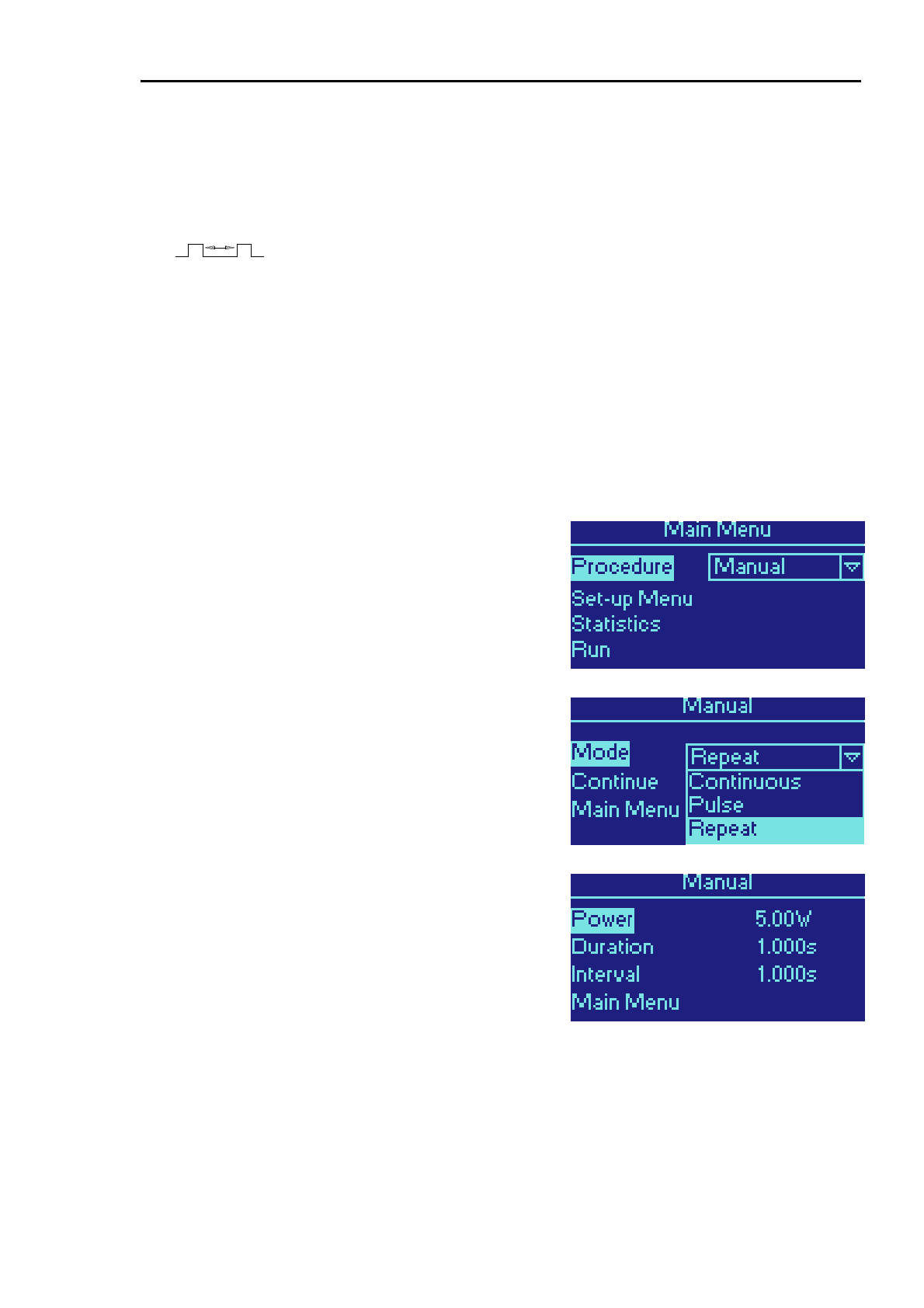
• Some DIOMED FRS fibers allow free setting of parameters. This is enabled by selecting
Manual from the Procedure menu.
• DIOMED supply a general purpose bare-ended fiber fitted with FRS, that sets the DIOMED
DELTA 15/30 to use Manual settings.
• Third party fibers
5
may also be used with the DIOMED DELTA 15/30. But these must first be
fitted with a special DIOMED FRS adapter, available from your DIOMED representative.
If a DIOMED FRS fiber is detected but no compatible procedure is installed, please
contact your local DIOMED representative who will advise on how you can update
the procedures installed in your DIOMED DELTA 15/30.
Parameters
Table 1. The following parameters may be adjusted manually.
The available modes are:
Continuous (not with a Spot Handpiece)
Pulse
Mode
Repeat Pulse
Power (W) Power may be adjusted in all operating modes:
Fiber:
0.5W to 5W in 0.5W increments
5W to maximum W in 1W increments
Spot Handpiece:
0.5W to maximum W in 0.1W increments
Pulse Duration (s) The pulse duration may be adjusted in Pulse and Repeat pulse modes:
Fiber:
5
DIOMED do not recommend the use of third party fibers as their quality and efficacy cannot be
guaranteed. Any damage caused to your DIOMED DELTA 15/30 by using a fiber not supplied by
DIOMED may not by covered under the DIOMED warranty.
DELTA 15/30
DELTA 15/30 Operator Manual Page 3.21 Version B.2
0.1 to 9.9 seconds in 0.1 second increments in single pulse mode
0.1 to 1.0 seconds in 0.1 second increments in repeat pulse mode
Spot Handpiece:
50 to 250 ms in 10 ms increments in single or repeat pulse mode
Interval (s) The interval between the pulses may be adjusted only in the Repeat pulse mode:
0.1 to 1.0 seconds in 0.1 second increments
Timer (s) Provides a countdown timer in Continuous and Repeat Pulse modes:
OFF to 120 seconds in 10 second increments
120 to 9999 seconds in 30 second increments (final increment of 9 seconds)
Table 2. The default parameters for each available mode are:
Mode Power Pulse Duration Pulse Interval Timer
Continuous 5 W Not available Not available OFF
Pulse 5 W 1 sec Not available Not available
Repeat Pulse 5 W 1 sec 1 sec OFF
Selecting Manual Operation
Manual operation allows the operator complete freedom
over the settings of the DIOMED DELTA 15/30 and is
enabled by selecting Manual from the Procedure menu.
Setting the Mode
The default mode is shown at the top of the menu. To
select a different mode turn the SCROLL knob until Mode
is highlighted and press CONFIRM. Select the desired
mode with the SCROLL knob and press CONFIRM again.
When the mode has been selected, highlight Continue
using the SCROLL knob and press CONFIRM.
Setting Power, Pulse Duration and Interval
Depending on the Mode selected, the next screen will show
a set of default parameters, as described in table 2 above.
To adjust a parameter, turn the SCROLL knob to highlight
the required parameter and press CONFIRM. The highlight
will now move to the value on the right hand side of the
display. Turn the SCROLL knob to adjust the value within
the range shown in table 1 and press CONFIRM. The
highlight will move back to the left hand side of the display.
Repeat this process for the other parameters as required.

DELTA 15/30
DELTA 15/30 Operator Manual Page 3.22 Version B.2
When you have completed setting up the operating
parameters, turn the SCROLL knob to highlight Continue
and press CONFIRM.
When the operating Mode is Continuous, the Pulse & Interval parameters are not
applicable and cannot be adjusted.
Similarly in Pulse mode, the Interval parameter cannot be adjusted and the Timer
is not available.
Start the Procedure
The DIOMED DELTA 15/30 is now ready to start the
procedure. Press STANDBY/READY and wait for the
DIOMED DELTA 15/30 to enter the READY mode.
Depress the footswitch. An audible warning will be heard
during laser irradiation and the laser emission indicator will
be lit.
To pause treatment, release the footswitch. Press the
footswitch again to continue. To end treatment, release the
footswitch and return the unit to STANDBY.
To turn the DIOMED DELTA 15/30 off, turn the key switch
anti-clockwise, remove the key and switch off at the rear
panel.
Countdown Timer
Countdown mode is enabled by setting the value of the
Timer parameter to any value except OFF. This mode
allows:
• Longer CW exposure times than the maximum 9.9
seconds allowed when using the Pulse mode
• A train of pulses to be output for a fixed time in
Repeat Pulse mode
The Timer is not available if the Pulse mode is selected.
The default time is 60 seconds but the time can be set to
any value between 10 and 3200 seconds.
When the Timer is active and the footswitch is pressed to
start treatment, the display will show a countdown until zero
is reached or the footswitch is released. To restart the
countdown after the footswitch has been released press the
footswitch and the countdown will resume. When the
countdown reaches zero the system will automatically enter
STANDBY mode.
The countdown time cannot be adjusted after the footswitch
has been pressed unless the user returns to the Manual
Control menu, or the countdown time has been completed.

DELTA 15/30
DELTA 15/30 Operator Manual Page 3.23 Version B.2
SESSION FAULT EMERGENCY OVERRIDE
In extreme circumstances, such as a power cut or a technical problem, the DIOMED DELTA 15/30 will
need to be restarted and will log a Session Fault. If this occurs during a treatment then the fiber in use
may become invalid before the completion of the treatment.
In these circumstances, the Emergency Override may be activated to allow treatment to continue. This
option is only available immediately after the Session Fault has been cleared and will not work if an
attempt is made to use an expired or otherwise invalid fiber at any other time.
Select Emergency Override to use this option or Main Menu to cancel.
If the Emergency Override has already been used, then this option is not
available.
Resetting the Emergency Override
The Emergency Override can be reset by means of a special reset device (DIOMED part number
AS/598). One of these is supplied with the DIOMED DELTA 15/30.
Each device can only be used once, after which it is advisable to contact your DIOMED representative
as soon as possible to obtain a replacement.
To reset the Emergency Override:
• Switch on the laser
• Attach the device by screwing it on to the laser aperture port, in the same way as you would
attach a fiber
• The DIOMED DELTA 15/30 will detect the device and reset the Emergency Override and
display a message on the screen
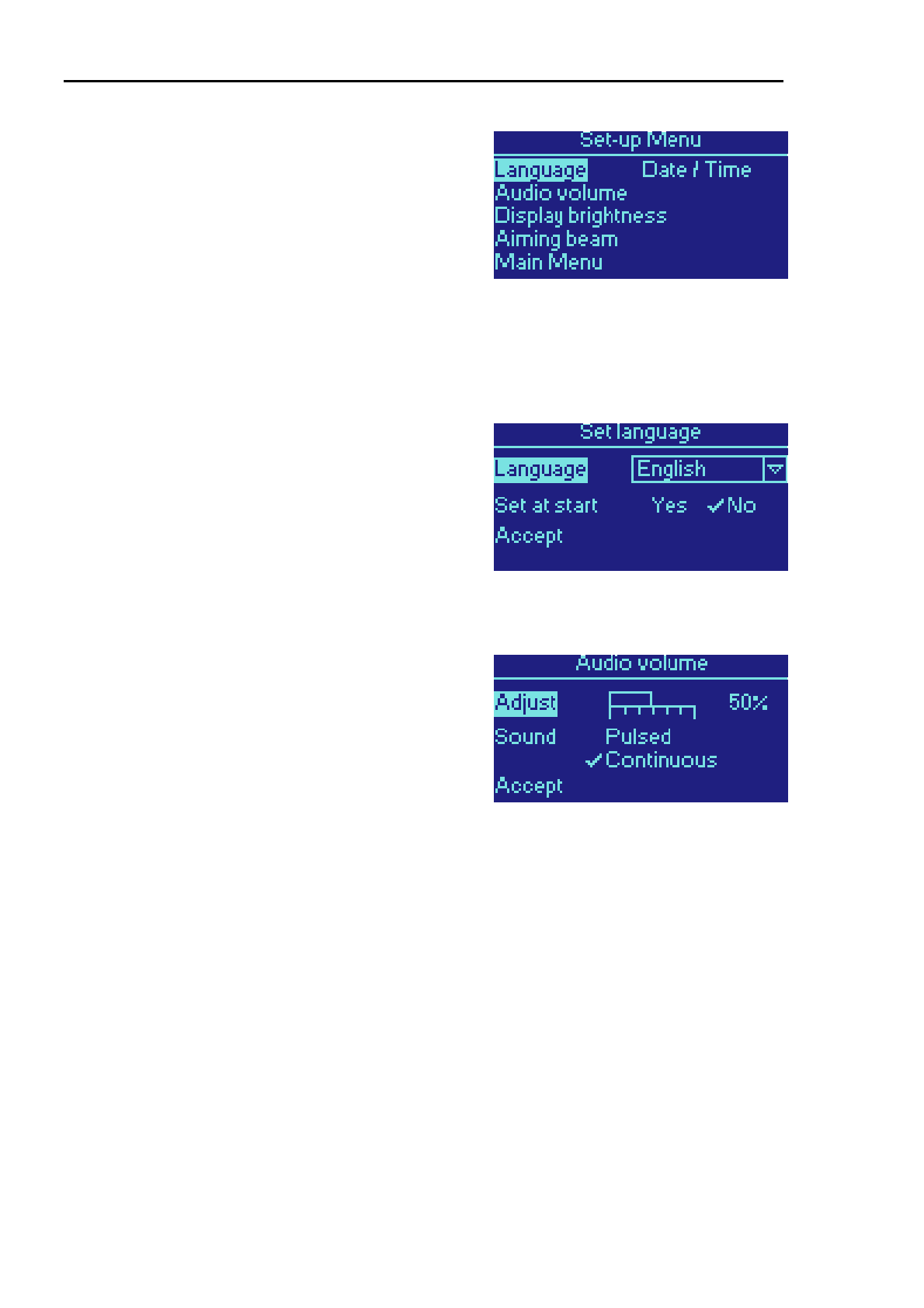
DELTA 15/30
DELTA 15/30 Operator Manual Page 3.24 Version B.2
SET-UP MENU
The Set-up Menu is available from the Main Menu. It
allows the operator to customise certain properties of the
DIOMED DELTA 15/30.
To access any of the functions within the Set-up Menu turn
the SCROLL knob until the function is highlighted and then
press CONFIRM.
To return to the Set-up Menu from any of these functions,
highlight Accept and press CONFIRM.
All of the changes made from this menu will be retained
when the DIOMED DELTA 15/30 is switched off.
Language
To change the language used for the user interface, turn
the SCROLL knob to highlight Language and press
CONFIRM. Now use the SCROLL knob to select the
required language from the drop down list and press
CONFIRM.
When Set at start is set to Yes, this language selection
screen will occur every time that the DIOMED DELTA
15/30 is switched on. This option can be toggled between
Yes and No by using the SCROLL knob to highlight Set at
start and pressing CONFIRM.
Audio Volume
To adjust the volume of the audible indicator heard when
the laser is firing, turn the SCROLL knob to highlight
Adjust and press CONFIRM. Now use the SCROLL knob
to select the required volume. Press CONFIRM when
finished.
If the volume is set to 0% the audible indicator is switched
off. In this case the visible laser emission indicator is the
sole indication of laser activity
The audible indicator can also operate in two modes, which
can be selected by choosing Sound with the SCROLL
knob:
• Pulsed – the audible indicator pulses in time with
the laser output (as long as the pulses are long
enough to be discernable)
• Continuous – the audible indicator sounds
continuously when the laser is firing
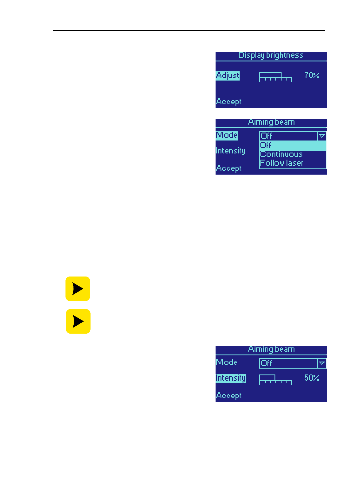
DELTA 15/30
DELTA 15/30 Operator Manual Page 3.25 Version B.2
Display Brightness
To adjust the brightness of the display, turn the SCROLL
knob to highlight Adjust and press CONFIRM. Now use the
SCROLL knob to select the required brightness. Press
CONFIRM when finished.
Aiming Beam
Mode
The aiming beam can operate in three modes, which can
be selected by choosing Mode with the SCROLL knob:
• Off – the aiming beam is switched off
• Continuous – the aiming beam is on continuously
when the laser is firing
• Follow laser - the aiming beam pulses in time with
the laser output (as long as the pulses are long
enough to be discernable)
The Follow laser mode is a useful aid for the operator as it
causes the aiming beam to mimic the characteristics of the
procedure. For example, if the laser output is pulsing one
second on and one second off then the aiming beam will
pulse at the same rate. Similarly, if the intensity of the laser
output varies then so will the aiming beam’s intensity.
In this mode, the aiming beam’s output will always provide
a visual indication that the laser is active, even if the output
is very low or very short, infrequent pulses.
If using the laser in non-contact mode, it is advisable to have the aiming beam
switched on to identify the target tissue that will be affected by the laser energy.
To observe the different modes of the aiming beam, place the DIOMED DELTA
15/30 into READY mode by pressing the STANDBY/READY button. The aiming
beam will be activated if Continuous or Follow Laser are selected. For safety, it
is not possible to fire the laser in READY state at this menu.
Intensity
To adjust the intensity of the aiming beam, turn the
SCROLL knob to highlight Intensity and press CONFIRM.
Now use the SCROLL knob to select the required intensity.
Press CONFIRM when finished.
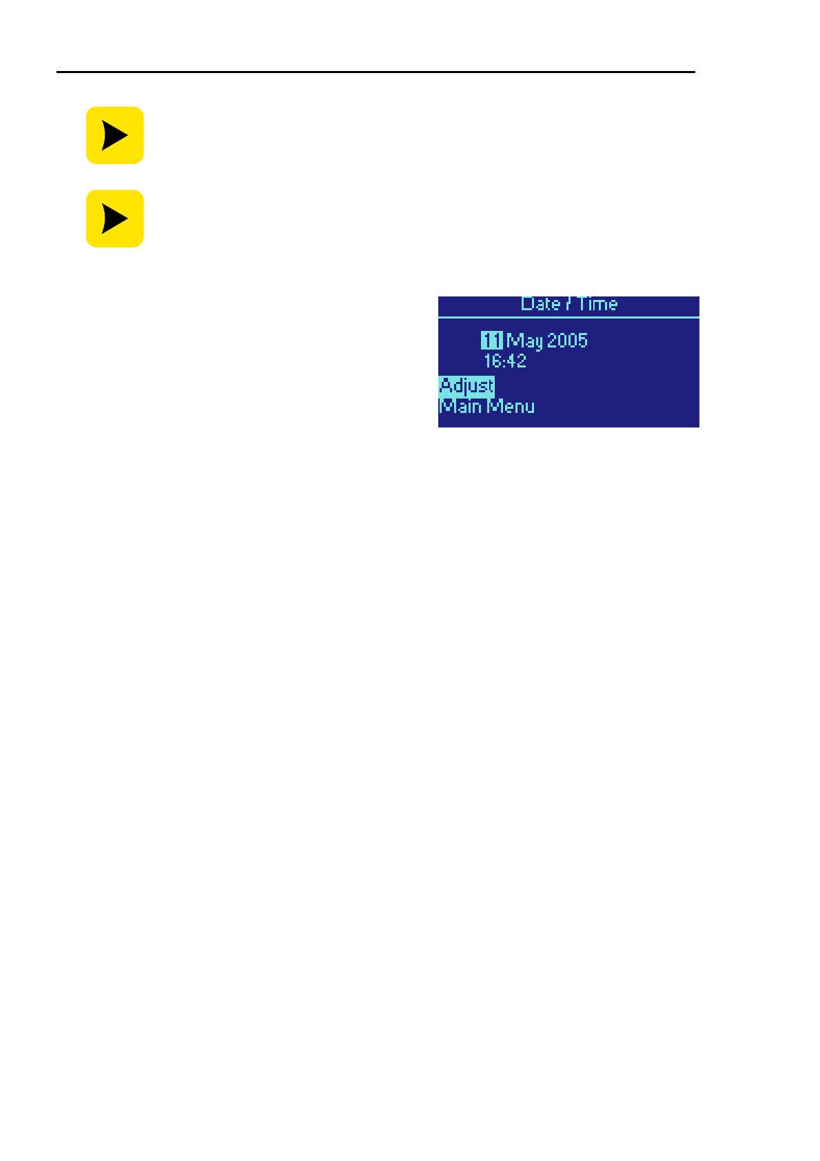
DELTA 15/30
DELTA 15/30 Operator Manual Page 3.26 Version B.2
The intensity adjustment will be ignored if the aiming mode is Off.
To observe the intensity of the aiming beam, place the DIOMED DELTA 15/30 into
READY state by pressing the STANDBY/READY key. The aiming beam will be
activated. For safety, it is not possible to fire the laser in READY state at this
menu.
Time & Date
To set the internal clock and calendar of the DIOMED
DELTA 15/30 turn the SCROLL knob to highlight Adjust
and press CONFIRM. Turn the SCROLL knob to change
the highlighted value and press CONFIRM to accept and
move on.
The order of adjustment is Day, Month, Year, Hours &
Minutes.
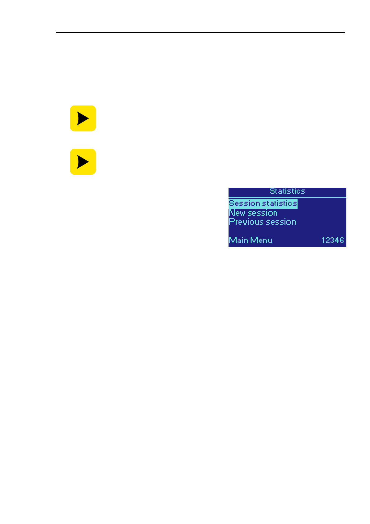
DELTA 15/30
DELTA 15/30 Operator Manual Page 3.27 Version B.2
SESSION STATISTICS
Session Statistics can be defined as a summary of the laser energy delivered and are recorded for the
time that the DIOMED DELTA 15/30 is switched on. Session Statistics will be displayed as the amount
of joules of energy delivered.
Each time the treatment parameters are changed, the Session Statistics will be shown on a separate
line of the screen. The total amount of laser energy used in this session will be displayed on the screen.
Session Statistics are stored in the DIOMED DELTA 15/30 internal memory. They
may also be transferred to a PC using a MMC memory card.
To minimise the risk of error, it is advisable to transfer Session Statistics from the
DIOMED DELTA 15/30 to a PC immediately after the procedure has been
completed.
The Statistics menu enables the operator to view the
session statistics from the current or previous sessions.
To access this menu turn the SCROLL knob until
Statistics is highlighted in the Main Menu and then press
CONFIRM.
To access any of the functions within the Session Statistics
menu turn the SCROLL knob until the function is
highlighted and then press CONFIRM.
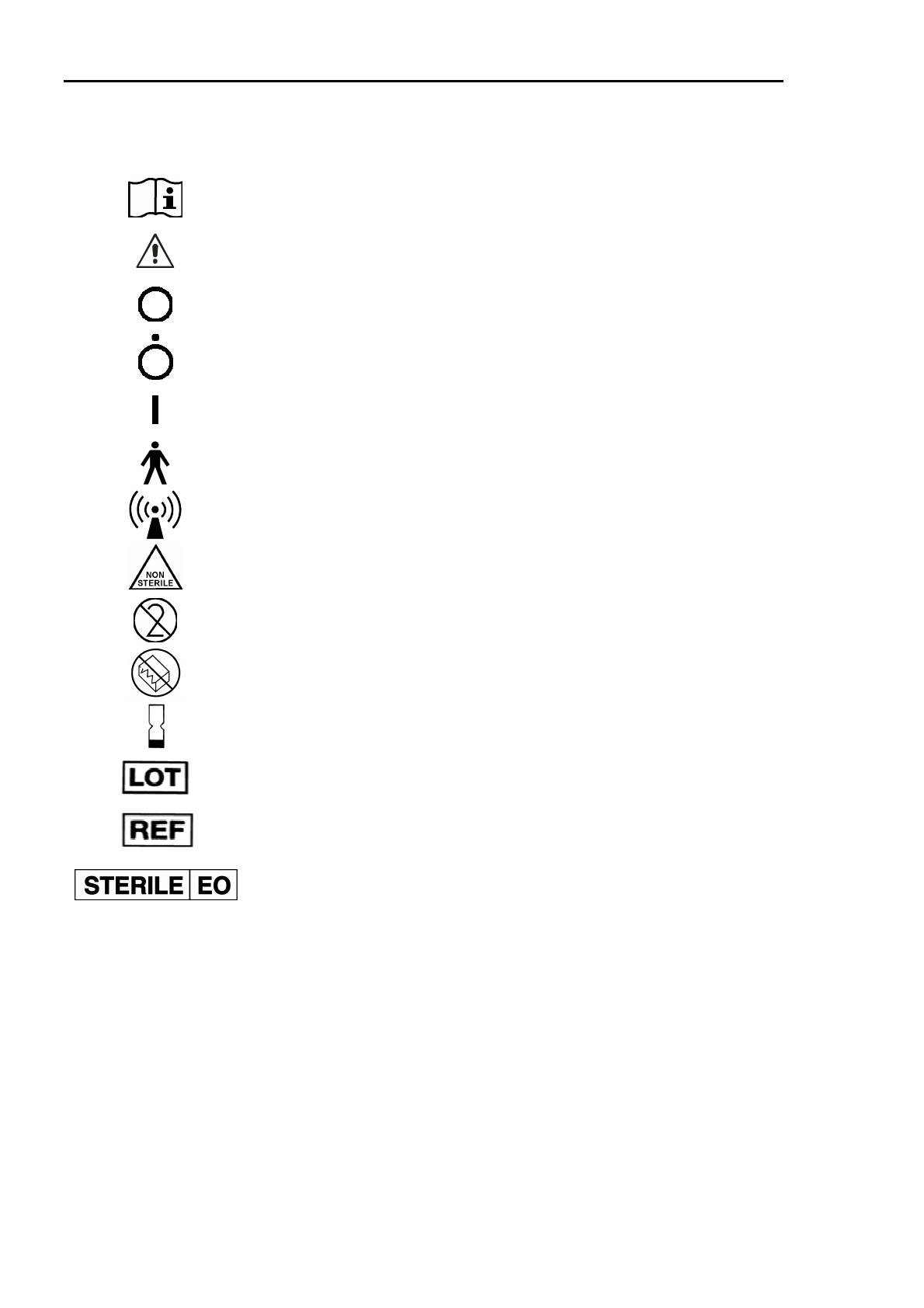
DELTA 15/30
DELTA 15/30 Operator Manual Page 3.28 Version B.2
SYMBOLS USED ON DIOMED PRODUCTS
The following symbols are used on the DIOMED DELTA 15/30 laser and on accessories provided by
DIOMED.
Refer to instructions
Refer to instructions (alternative)
Power Off
Power Off (only for a part of equipment)
Power On
Type B applied part
Intentional radiator
The component or accessory is non-sterile
Single-use
Do not use if packaging is damaged
Expiry date
Batch number
Product re-order code
Sterile by Ethylene Oxide

DELTA 15/30
DELTA 15/30 Operator Manual Page 4.1 Version B.2
SECTION 4 PROCEDURES
The DIOMED DELTA 15/30 lasers are optimised to operate with DIOMED fibers and procedure kits that
are equipped with the DIOMED Fiber Recognition System (FRS). For a full description of this system
please see section 3 of this manual.
This section describes the FRS fibers, procedure kits and other accessories that are currently available
from your DIOMED representative.
DIOMED’s policy of continual product development and improvement means that fibers and procedure
kits may be added to the product range at any time. Therefore the information in this section may
change without notice. Please contact your DIOMED representative to obtain the latest product
information.
CONTENTS
Section 4
PROCEDURES .................................................................................................................... 1
Contents ................................................................................................................................................. 1
Diomed Fibers and Procedures.............................................................................................................. 2
Ordering Information............................................................................................................................... 2
EVLT....................................................................................................................................................... 3
Spot Handpieces .................................................................................................................................... 4
Bare-ended Fiber.................................................................................................................................... 4
Manual Adapter ...................................................................................................................................... 4
Test Fiber................................................................................................................................................ 4
Emergency Override Reset Device ........................................................................................................ 4

DELTA 15/30
DELTA 15/30 Operator Manual Page 4.2 Version B.2
DIOMED FIBERS AND PROCEDURES
When a DIOMED fiber fitted with FRS is connected to a DIOMED DELTA 15/30 laser, the laser will
attempt to recognise the type of fiber from the information stored in the FRS gripper. If successful, it will
cross-reference the type of fiber with an internal database of compatible procedures. Any procedures
that are compatible with the connected fiber are listed in the Procedure menu and may be selected by
the operator.
From time to time, Diomed will release new fibers, and procedure kits. In order to use these, your
DIOMED DELTA 15/30 will need to be updated with the latest procedure information.
ORDERING INFORMATION
The following order codes should be quoted when ordering replacement procedure kits, fibers and
accessories for your DIOMED DELTA 15/30.
Description DIOMED or fibersdirect.com part number
EVLT Procedure Kit EVLT/PK-02
EVLT Procedure Kit – Extra Length EVLT/PK-02-EL
Micro-Introducer Kit EVLT/PK/MIK
2mm Spot Handpiece replacement fiber only AS/0618
4mm Spot Handpiece replacement fiber only AS/0619
Manual Adapter AS/0686
Test fiber AS/0604
Emergency Override Reset Device AS/0598
MMC Multimedia Memory Card S10/06/0086
USB MMC Card Reader/Writer S10/06/0087
DIOMED Key Fob / MMC Card Holder AS/0685
This list was correct at the time of publication but new procedure kits, fibers and accessories may be
added at any time. Please check with your local DIOMED representative for the latest information.
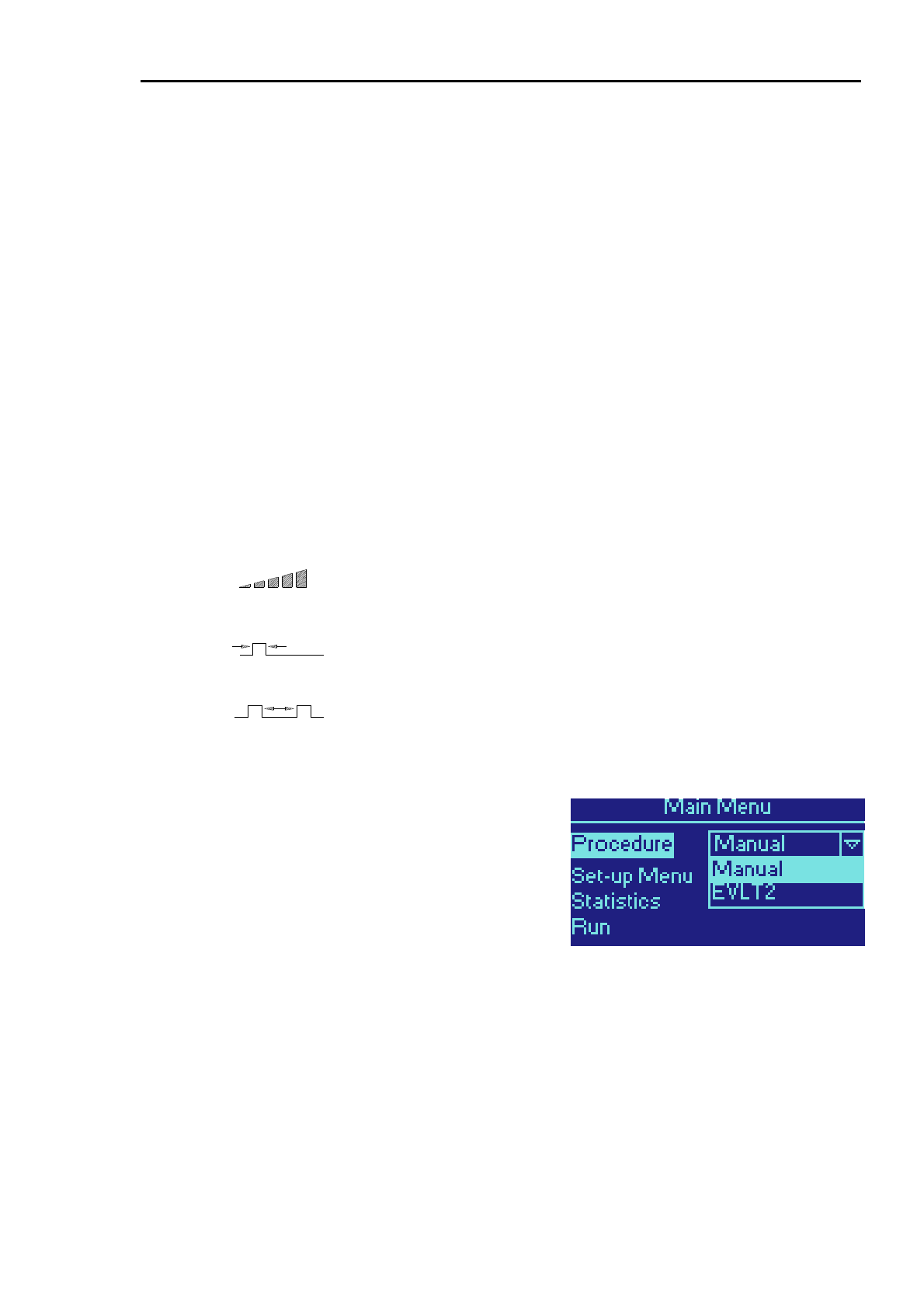
DELTA 15/30
DELTA 15/30 Operator Manual Page 4.3 Version B.2
EVLT
There are three procedures that are compatible with the EVLT procedure kit. Two of these are designed
to cover the currently-approved methods for performing an EVLT procedure. The third is intended to
allow the operator some freedom in setting parameters manually.
Note: If the DIOMED DELTA 15/30 laser is also enabled for Manual operation, then it may also be
configured for any parameters within its design specifications.
EVLT Continuous
The laser output power is fixed at a continuous 14 W. No adjustments can be made.
EVLT Pulsed
The laser output power is fixed at 12 W with a 1 second pulse and 1 second interval. No adjustments
can be made.
EVLT Manual
The laser output power may be varied between 5 W and 15 W. The mode may be switched between
continuous output and 1 second pulses with 1 second interval.
These three procedures are summarised in the following table:
EVLT Continuous EVLT Pulsed EVLT Manual
Power (W)
14 W 12 W 5 W to 15 W
Pulse Duration (s)
1 second
Interval (s)
Continuous
1 second
Continuous
or
1 second Pulse /
1 second Interval
Selecting the Procedure
The default procedure is shown at the top of the menu. To
select a different procedure turn the SCROLL knob until
Procedure is highlighted and press CONFIRM. Select the
desired procedure with the SCROLL knob and press
CONFIRM again.
When the required procedure has been selected, highlight
Run using the SCROLL knob and press CONFIRM.
Adjusting an EVLT procedure
The EVLT Continuous and EVLT Pulsed procedures use preset parameters and cannot be adjusted.
The EVLT Manual procedure allows the power to be adjusted between 5 W and 15 W and the mode

DELTA 15/30
DELTA 15/30 Operator Manual Page 4.4 Version B.2
may be switched between Continuous and Pulsed. The pulse duration and interval are preset to 1
second.
Instructions on how to select mode and adjust power are included in section 3 – Operating Instructions.
SPOT HANDPIECES
When a DIOMED spot handpiece is connected to the DIOMED DELTA 15/30, FRS will recognise the
type of handpiece and automatically displays suitable preset parameters. Follow the operating
instructions in section 3.
BARE-ENDED FIBER
When a DIOMED bare-ended fiber is connected to the DIOMED DELTA 15/30, FRS will recognise the
type of fiber and automatically select the manual mode for the laser. Follow the operating instructions in
section 3.
MANUAL ADAPTER
If you wish to use a fiber not supplied by DIOMED then, in certain circumstances, it is possible to use a
special adapter to enable the fiber to be accepted by the Fiber Recognition System. The DIOMED
DELTA 15/30 will then be enabled for Manual operation.
For details of this adapter please contact your DIOMED representative.
TEST FIBER
The test fiber is a special type of FRS fiber used during testing and evaluation only.
EMERGENCY OVERRIDE RESET DEVICE
The Emergency Override Reset Device consists of a special FRS gripper, supplied without a fiber.
Instructions on when and how to use this device are in section 3.

DELTA 15/30
DELTA 15/30 Operator Manual Page 5.1 Version B.2
SECTION 5 TECHNICAL INFORMATION
The DIOMED DELTA 15/30 has been designed to operate reliably with minimal maintenance and there
are no user serviceable parts.
This section includes technical data and describes the routine maintenance procedures that you can
perform on the DIOMED DELTA 15/30 and its accessories.
Any attempts to repair, adjust or modify the laser beyond the procedures allowed in this Operator
Manual, by any person not authorised by DIOMED, will invalidate the guarantee.
CONTENTS
Section 5
TECHNICAL INFORMATION............................................................................................... 1
Contents ................................................................................................................................................. 1
Specifications.......................................................................................................................................... 2
Classification........................................................................................................................................... 3
Cleaning the DIOMED DELTA 15/30 ..................................................................................................... 3
Caring for fibers ...................................................................................................................................... 3
Troubleshooting...................................................................................................................................... 4
Accessories ............................................................................................................................................ 7
Sterilisation of Optical Fibers.................................................................................................................. 8
Surgical Handpieces............................................................................................................................... 8
Fixed Focus Spot Handpiece Maintenance............................................................................................ 9
Fuse Replacement ................................................................................................................................. 9
Disposal.................................................................................................................................................. 9
Software updates.................................................................................................................................... 9
Calibration............................................................................................................................................. 10
Laser Power Output.............................................................................................................................. 13
Technical Description ........................................................................................................................... 15

DELTA 15/30
DELTA 15/30 Operator Manual Page 5.2 Version B.2
SPECIFICATIONS
DIOMED DELTA 15 DIOMED DELTA 30
Laser Type Diode laser, CW
Centre wavelength 810 nm
Spectral bandwidth 90% of optical power contained within 810 ± 20 nm
Delivery fiber Minimum 400 µm diameter, 0.37 Numerical Aperture (NA)
Fiber connector Optical SMA-905 to MIL STD
Maximum Power 15 W to the laser output port 30 W to the laser output port
Minimum Power 0.5 W to the laser output port
Set power accuracy Better than ± 10% of displayed power
Output power stability ± 5% maximum
Aiming beam Red Class 3a diode laser, ≤ 5 mW at port, wavelength 635-655 nm
100 ms – 9900 ms
Pulse duration
Continuous Wave (CW)
Pulse Interval 100 ms – 1000 ms
Countdown timer 10 – 3200 seconds
Contact fibers, 400µm, 600µm and 1000µm
Fibers
Non-contact fibers, 600µm & 1000µm
Calibration Internal power calibration meter for handpiece or fiber calibration
(Optional on DIOMED DELTA 15)
Spot Handpiece Mode Spot handpiece mode is available on the DIOMED DELTA 30 and on the DIOMED
DELTA 15 when fitted with the optional calibration meter
Spot size Ø 2mm Ø 2mm , Ø 4mm
Single/Repeat Pulse 50ms – 250ms 50ms – 950ms
Pulse Interval 100ms – 1000ms 100ms – 1000ms
Fluence Up to 119J/cm
2
Up to 400J/cm
2
Fiber Recognition System (FRS)
Operating Frequency 125 kHz ± 1 kHz
Operating Range Maximum of 40 mm from the laser output port
RFID Modulation Type A1D
Standards FCC 47 Part 15c, Canadian RSS-210
EN 300 330-1, EN 300 330-2, EN 301 489-1, EN 301 489-3
Cooling By ambient air, with fan assistance
Power Supply 100 – 240 V AC, 50 – 60 Hz, 500 VA max.
Dimensions (H x W x D) 150 mm x 370 mm x 325 mm (± 5 mm)
Weight 12 kg max.
Up to 15W CW +10ºC to +40ºC
Operating Temperature +10ºC to +40ºC
Over 15W CW +10ºC to +30ºC
Operating Humidity Up to 75% relative humidity, non-condensing
Operating Pressure Normal atmospheric pressure
Storage Temperature 0ºC to +55ºC
Storage Humidity Up to 90% relative humidity, including condensing
Storage Pressure 500 hPa to 1014 hPa
Safety Standards EN 60601-1, EN 60601-1-2, EN 60601-2-22, EN 60825-1, 21 CFR 1040.10, 1040.11

DELTA 15/30
DELTA 15/30 Operator Manual Page 5.3 Version B.2
CLASSIFICATION
Type of protection from electric shock Class I
Degree of protection from electric shock Type B
Degree of protection against ingress of water IP21
CLEANING THE DIOMED DELTA 15/30
The DIOMED DELTA 15/30 has been designed to operate reliably with minimal maintenance. There are
no user-serviceable parts in the DIOMED DELTA 15/30. Any attempts to repair, adjust or modify the
system beyond the procedures allowed in this Operator Manual, by any person not authorised by
DIOMED, will invalidate the guarantee.
The system enclosure may be wiped down periodically with a cloth dampened with a mild antiseptic
solution. Before cleaning always disconnect the DIOMED DELTA 15/30 from the AC supply. Do not use
any other solutions, solvents or abrasives. Take care not to get any liquid inside the enclosure.
CARING FOR FIBERS
Safety Carefully read and follow the package insert instructions for use.
Handling Leave the fiber tip protector in place during the uncoiling and
connection process.
To verify the integrity of the fiber, check the fiber for any breaks by
overall visual inspection. For non-contact fibers, ensure the laser is
in READY mode, and direct the aiming beam at a flat, white surface
positioned 50-70mm away and examine the spot formed. The central
spot should be symmetrical and the outer circle uniform in both
intensity and shape.
Pre-Carbonisation of
sculpted tip (contact)
fibers
Prior to use on the patient, an enhanced tissue effect can be achieved
by establishing a plane of microcarbon on the face (end) of the contact
tip. A plane of carbon traps the laser energy within the fiber tip,
resulting in increased efficiency at lower powers.
1. Using sterile technique, darken a small area (l) on a wooden
tongue depressor/spatula with a surgical marker.
2. Pass the fiber into surgical field.
3. Set the laser power at 10 Watts continuous.
4. Observing the safety procedures described in this Operator
Manual, gently touch tip of the fiber to the darkened area on the
tongue depressor and operate laser only until a small plume of
smoke appears.
5. The fiber has now been pre-carbonised and is ready for clinical
use.
6. Reset the laser to the correct power setting and duration for
desired procedure.

DELTA 15/30
DELTA 15/30 Operator Manual Page 5.4 Version B.2
Delivery Fiber Calibration
Non-contact fibers with a cooling sheath can be calibrated using the
calibration procedure described in Section 3 – Operating Instructions.
Contact laser fibers do NOT require calibration.
Cooling for reusable tip
contact and non-contact
fibers with gas/fluid
cooling
Fibers with gas/fluid cooling have a protective catheter with the distal
tip secured in a metal ferrule. Fibers with reusable contact tips have
threaded ferrules for contact tip connection. On this type of fiber, gas,
air or distilled water is introduced near the proximal end through an
auxiliary line that has a luer lock connection. The purpose of the
cooling is to keep the distal end of fibers clean and cool during use.
Gas, air or fluid supply is not provided with the laser system. Typical
flow rates for the gas and air are from 0.2 to 1.5 l/min with minimum
pressure of 50-60 psi and for the fluid cooling from 2 to 20 ml/min.
Application to tissue When using a conical tip contact fiber, all of the energy is being
delivered out of the tip. There is a minimal tissue effect with the side
of the tip. The best results will be obtained when holding the tip of the
fiber perpendicular to the tissue and applying extremely light
pressure with the tip. Haemostasis occurs as the tissue is incised.
The orb tip contact fiber is also used for cutting tissue. The laser
energy is displaced outwards from the side of the fiber, providing the
added advantage of coagulating larger tissue surfaces.
Both styles of tips work best when applied lightly to the surface and
not buried in the tissue. Cross traction on tissue increases laser
effect and extends life of fiber tip.
TROUBLESHOOTING
Error Messages
The DIOMED DELTA 15/30 is continuously monitoring its operation and performance. Should it detect a
problem it will display a short message on the screen. To clear a message, carry out the instructions on
the display. Outlined below are some common messages and the appropriate action that the user
should undertake.
Remote interlock The remote interlock has been violated. Close the entry door or insert the
remote interlock bypass into the remote interlock bypass socket on the
rear of the unit.
Footswitch not connected The laser system will not go to READY mode unless the footswitch has
been connected. Connect the footswitch and ensure that it is correctly
inserted into the footswitch socket.
Fiber not connected
The optical fiber or spot handpiece is disconnected from the laser.
Connect a handpiece or fiber to the laser output port.

DELTA 15/30
DELTA 15/30 Operator Manual Page 5.5 Version B.2
Emergency switch
pressed. Use key switch to
reset
The emergency switch has been pressed. Switch the laser OFF and ON
using the key switch. The laser will carry out a self-test and the message
will clear automatically.
Fiber calibration failed An attempt has been made to calibrate a non-contact fiber and the
calibration has failed (below 75%). Replace the fiber and re-calibrate.
Setting Wavelength This message will occur when the temperature of the laser diode is
outside of its specified operating range for the correct diode wavelength.
Leave the laser on to allow the temperature to stabilise. This may take a
few minutes.
Ambient temperature out
of range The laser is being operated outside of its specified ambient temperature
range. Switch it off at the mains inlet and allow it to stabilise at room
temperature.
Temperature high The laser is overheating. Switch it off at the mains inlet and allow it to
cool.
Footswitch held down There is a two-second safety delay when the laser is placed from
STANDBY to READY. Ensure that the footswitch is not held down until
after the two-second delay and the audible beep is heard. The message
will clear when the footswitch is released.
Diode switched off The laser has been prevented from firing. Press SELECT and check the
maximum power available.
Software loading
unsuccessful A problem was detected when loading new software. Switch the laser
OFF and then ON at the key switch and repeat the software load process.
If the problem is repeated, call for support from your DIOMED
representative.
Footswitch invalid The laser has detected a problem with the footswitch. Check that the
footswitch has been connected correctly. If the message does not clear,
switch the laser OFF and then ON at the key switch. If this does not clear
the problem, call for support from your DIOMED representative.
Panel switch stuck A switch on the front panel has stuck during switch-on, and the laser will
not be able to go into the READY mode. Switch the laser OFF and ON
using the key switch. If this does not clear the message, call for a service
engineer.
Call service engineer If this message appears, switch the laser OFF at the key switch and then
ON. If the message does not disappear, call service support from your
DIOMED representative.
FRS Error Messages
The following error messages are associated with the Fiber Recognition System.

DELTA 15/30
DELTA 15/30 Operator Manual Page 5.6 Version B.2
FRS Error The laser has detected a problem with the FRS system for identifying
fibers. Try removing and replacing the fiber connector or connecting a new
fiber.
If the message does not clear, switch the laser OFF and then ON at the
key switch. If this does not clear the problem, call for support from your
DIOMED representative.
Fiber uses expired All the available uses of the connected fiber have expired. Replace the
fiber with a fiber that has uses remaining.
Fiber sterility expired DIOMED fibers are programmed at manufacture with a sterility expiration
date. This message is displayed when the expiry date is before the date in
the laser’s internal clock. Replace the fiber with one having a valid sterility
expiration date.
Invalid Fiber The fiber attached to the DIOMED DELTA 15/30 is either not recognised
or not equipped with the FRS system. Replace with an appropriate fiber
or, if a Session Fault is indicated, use the Emergency Override option.
FRS Troubleshooting
The DIOMED FRS system has been extensively tested. In the unlikely event of a problem being
experienced please perform the following checks before contacting your local DIOMED representative
for further advice.
“Invalid Fiber” is displayed
even with a new unused
FRS system fiber
(1) Disconnect and then reconnect the fiber to the DIOMED DELTA
15/30. This will cause the unit to try and read the fiber’s data
again.
(2) Ensure that the DIOMED DELTA 15/30 is at least 2 meters
away from any other electrical or electronic equipment that
might interfere with the FRS system, such as computers or other
electronic or medical equipment.
I need to use a non-FRS
system fiber
Some versions of the DIOMED DELTA 15/30 can also operate with
non-DIOMED fibers, as long as they are fitted with a special
DIOMED adapter at the laser end of the fiber. This adapter is
available as an accessory from your DIOMED representative and it
will allow the DIOMED DELTA 15/30 to be used in Manual mode
only. See your DIOMED representative for further information.
The Emergency Override
option is not available After it has been used once, the Emergency Override option must be
reset before it can be used again, as described in ‘Resetting the
Emergency Override’ above. Contact your DIOMED representative
to obtain a spare reset device.
The fiber is still within its
sterility date but the laser
shows it as expired
Check that the date of the internal clock in the DIOMED DELTA
15/30 is set correctly. The procedure for setting the clock is
described in Section 3 - Operator Instructions.

DELTA 15/30
DELTA 15/30 Operator Manual Page 5.7 Version B.2
ACCESSORIES
Optical Fibers The DIOMED DELTA 15/30 has an output connector for optical
fibers with standard SMA-905 connector. Only DIOMED or
fibersdirect.com labelled fibers should be used. A list of fibers
available for use with the DIOMED DELTA 15/30 can be
obtained from your DIOMED representative.
Contact Sculpted Tip Fibers Used in contact with the tissue for incision/excision.
Conical Tip Fibers DIOMED conical tip fibers have a tip size of 300µm and should
be selected where a narrow or precise incision/excision is
required. Laser energy is delivered from the end of the sculpted
tip with minimal tissue effect from the side of the tip. Heat
delivered via the tip performs the cutting and extremely light
pressure is all that is required for incising, excising and
vaporising and coagulating soft tissue. Haemostasis occurs as
the tissue is incised.
Orb Tip Fibers DIOMED orb tip fibers are available with tip sizes of 800µm,
1200µm and 3000µm and should be selected where a wider
incision or tissue vaporisation is required. Laser energy is
displaced outwards from the forward curvature of the fiber
which gives the added advantage of vaporising larger tissue
surfaces. Heat delivered via the tip performs the cutting and
extremely light pressure is all that is required for incising,
excising and vaporising and coagulating soft tissue.
Haemostasis occurs as the tissue is incised.
Bare/Flat end fibers Used in contact with the tissue for incision/ excision and in non-
contact with tissue at low power for vaporisation / coagulation.
Non-contact cooled fibers Held at a distance from the tissue for vaporisation / coagulation.
DELTA 15/30
DELTA 15/30 Operator Manual Page 5.8 Version B.2
STERILISATION OF OPTICAL FIBERS
Optical fibers are provided sterile as a disposable, single-use
product.
DO NOT RE-STERILISE THE FIBERS.
DO NOT RE-USE THE FIBERS.
USE ONLY DIOMED OR FIBERSDIRECT.COM LABELLED OR
DIOMED APPROVED FIBERS.
Failure to observe this could invalidate the Laser Guarantee.
Intra-operative cleaning If the tip accumulates debris, turn the laser to the STANDBY mode
and then carefully wipe the tip clean with a wet sponge/swab.
Fiber Disposal After use, the single-use optical fibers should be disposed of in
accordance with local regulations regarding disposal of contaminated
waste.
DIOMED and fibersdirect.com labelled optical fibers have
undergone stringent evaluation and testing to ensure that they
are of the highest quality and that they operate safely,
effectively and efficiently with DIOMED lasers.
The exact alignment of the interface between the laser aperture
and the SMA-905 connector is critical. Misalignment (as may
occur with non-approved fibers) can result in damage to the
laser and poor delivery of laser energy to the patient.
Calibration Port Adapter The optical fiber calibration port adapter provided should be sterilised
and used to locate the fiber in the calibration port.
Steam Sterilisation The calibration port adapter should be sterilised before use in
accordance with ISO 11134 1993 ‘Sterilisation of Healthcare Products,
Requirement for Validation and Routine Control, Industrial Moist Heat
Sterilisation.
A validated cycle of ≥134°C (273°F) for ≥ 3 minutes sterilising time
should be used to give a sterility Quality Assurance of 10
6
.
SURGICAL HANDPIECES
Surgical handpieces with either rigid or malleable cannulae can be obtained from your DIOMED
representative. These are available in a range of lengths and internal /external diameters.
A full description and list of handpieces is available from your local DIOMED representative.
Guildelines If the requirement is to use a fiber with a separate handpiece, the
following guidelines must be followed:
1. Remove the fiber from the sterile packaging in accordance with the
fiber instructions.
2. Ensure that the handpiece is sterile, loosen the locking nut at the
rear of the handpiece.
To prevent any premature damage to the fiber when using
malleable handpieces, ensure that the malleable part on the
handpiece has been straightened before inserting the fiber. Only

DELTA 15/30
DELTA 15/30 Operator Manual Page 5.9 Version B.2
shape the handpiece after the fiber has been inserted.
3. Insert the fiber down the handpiece from the rear until the fiber 'tip'
protrudes approximately 10mm from the distal end of the
handpiece.
4. Tighten the lock nut at the rear of the handpiece finger tight.
5. The fiber is now ready for use.
Cleaning and Sterilisation After use, remove the fiber from the handpiece, wipe down the
outside of the handpiece with alcohol. Insert a syringe full of water
into the rear of the handpiece and depress the plunger to flush out
any remaining debris. The handpiece can now be sterilised using a
validated steam sterilisation cycle.
Steam Sterilisation Reusable handpieces should be sterilised before use in accordance
with ISO 11134 1993 ‘Sterilisation of Healthcare Products,
Requirement for Validation and Routine Control, Industrial Moist Heat
Sterilisation. A validated cycle of ≥134°C (273°F) for ≥ 3 minutes
sterilising time should be used to give a sterility Quality Assurance of
10
6
.
FIXED FOCUS SPOT HANDPIECE MAINTENANCE
For information on the care and maintenance of the Fixed Focus Spot Handpieces, see the Instructions
for Use supplied with each handpiece.
FUSE REPLACEMENT
Spare mains fuses are supplied with the DIOMED DELTA 15/30. Further spares can be obtained from
DIOMED. They can be replaced as follows:
1. Use a small flat-bladed screwdriver to release the fuse compartment from the mains inlet on the
rear panel.
2. Remove the two fuses from the holder and replace with new ones of the same type and rating:
T6.3A H 250V. Fuses with a different rating or specification must not be used.
DISPOSAL
At the end its life the DIOMED DELTA 15/30 should be disposed of according to national environmental
requirements or be returned to DIOMED
SOFTWARE UPDATES
From time to time DIOMED may issue new procedures, upgrades and feature enhancements for the
DIOMED DELTA 15/30. As a registered owner you will be notified of these when they become
available.

DELTA 15/30
DELTA 15/30 Operator Manual Page 5.10 Version B.2
CALIBRATION
Checking the Calibration of the Internal Power Meter
To ensure accurate calibration of the delivery fiber, the internal power meter should be checked at least
annually. The LASER SAFETY OFFICER or suitably trained service personnel should carry out this
procedure.
The method for carrying out this procedure is described below.
Calibrating the Internal Power Meter
THE FOLLOWING INFORMATION IS PROVIDED FOR REGULATORY PURPOSES
INCORRECT CALIBRATION MAY CAUSE INJURY DURING TREATMENT.
THE ENGINEERS INTERFACE MAY BY-PASS MANY OF THE NORMAL
SAFETY SYSTEMS.
DO NOT attempt the following procedures unless specifically authorised to
do so by DIOMED. Such action may cause exposure to hazardous laser
radiation and a risk of electrical shock. It may also result in damage to the
instrument and invalidate guarantee cover.
ONLY TRAINED LASER SERVICE PERSONNEL AUTHORISED BY
DIOMED SHOULD PERFORM SERVICE AND MAINTENANCE.
DIOMED will not accept liability for the use of this equipment when
calibrated by unauthorised personnel.
Calibrating the
internal power meter
To ensure accurate calibration of the delivery fiber, the internal power meter should
be checked at least annually and re-calibrated if necessary. This section describes
the procedure undertaken to re-calibrate the internal power meter.
Equipment required • DIOMED Engineer Interface software.
• Traceable power meter capable of recording a 10W, one second
pulse of 810nm Infra Red laser light.
• 600µm reference fiber.
Procedure The calibration of the internal power meter is controlled by two electronically
controlled potentiometers (EPOTs). These need to be set to scale the output
of the power meter correctly. These are normally adjusted for gain and
settling time using a production jig. Only the facility to adjust the gain is used
here.
Connect the laser to a PC via a null-modem serial cable between the port on
the rear panel and a serial port on the PC.
Turn on the laser.
Load and run the DIOMED Engineer Interface program on the PC. From the
Connection menu, select Connect to Laser, choose the appropriate
Comms Port and press Connect.

DELTA 15/30
DELTA 15/30 Operator Manual Page 5.11 Version B.2
From the Connection menu select Enter EI and enter the password.
Connect the fiber to the calibration port using a suitable adapter. In the
engineer interface, open the ‘Non-volatile details’ tab. Note down pot
settings 1 and 2 from the Calibration Port group. Set the laser to continuous
mode, 10W and put the laser into the ready state.
In the engineer interface, select Tests/ Read radiometer ADC. A
dialog box is shown, headed ‘Reading radiometer’ Fire the laser for not more
than 10s. The ADC readings are shown in the dialog. Note down the second
ADC reading. This does not have to be very accurate – we are just scaling
the radiometer output to fit in the ADC range. Put the value in the table
below.
Pot 1 setting Pot 2 setting Stage 2 ADC reading
Change the value of the Pot 1 setting to scale the stage 2 ADC reading to
around 700. This is done by closing the ‘Reading radiometer’ window,
altering the setting for pot 1, and clicking on the ‘Update’ button. Now repeat
the sequence, recording the new settings and ADC reading in the table.
Repeat until the ADC reading is between 650 and 750 counts.
Close the ‘Reading radiometer’ window and put the laser into the standby
state.
The radiometer amplifier circuit should now be scaled correctly. The next
step is to calibrate the radiometer, using calibration points for 1W and 10W,
which are stored in the on-board EEPROM. This step will require the
calibrated power meter.
With the laser in the standby state, select Set up/ Set up radiometer
from the engineer interface menu. The following prompt should be
displayed: ‘Put fiber in external meter and fire laser. Adjust power and press
control when set’. Set the power to 10W and fire the laser into the meter.
When the power reading has settled make adjustments using the rotary
control until the power displayed is exactly 10W.
When the power setting is achieved, release the footswitch and press the
rotary control. The following prompt should be displayed: ‘Put fiber in internal
meter and fire laser until cal pulse stops.’
Attach the fiber to the calibration port, put the laser into the ready state and
fire until the laser stops (allow about 8s). Release the footswitch.

DELTA 15/30
DELTA 15/30 Operator Manual Page 5.12 Version B.2
The following prompt should be displayed: ‘Put fiber in external meter and
fire laser. Adjust power and press control when set’.
Adjust the power setting to 1W and put the laser back into the ready state.
Fire the laser into the meter and, when the power reading has settled, make
adjustments using the rotary control until the power displayed is as close as
possible to 1W.
When the power setting is achieved, release the footswitch and press the
rotary control.
The following prompt should be displayed: ‘Put fiber in internal meter and
fire laser until cal pulse stops.’
Attach the fiber to the calibration port, put the laser into the ready state and
fire until the laser stops (allow about 8s). Release the footswitch.
Select ‘Back’
In the engineer interface, update the ‘Non-volatile details’ tab and read the
calibration port data. Write the data down in the table.
Pot setting 1
Pot setting 2
ADC at 1W port power
ADC at 10W port power
Checksum
The ‘ADC at 10W port power’ figure is the calibration point for 10W, which
we have just obtained with the set-up routine. Compare this with the value
noted previously when setting the radiometer gain. That reading was
obtained with 10W port power, while the calibration point was taken with
10W distal power, so the calibration point should be 1.1x the previous ADC
reading at 10W, allowing for a 90% fiber.

DELTA 15/30
DELTA 15/30 Operator Manual Page 5.13 Version B.2
LASER POWER OUTPUT
Measuring the Laser Power Output
The LASER SAFETY OFFICER or suitably trained service personnel should check the output power of
the DIOMED DELTA 15/30 at least annually from the date of installation, by following the procedure
described below.
Equipment Required • A sampling power meter or an independent energy (integrated
power) meter of known calibration
• A bare ended optical fiber
• Laser unit to be tested
Procedure Calibrate the fiber.
Connect the fiber to the Laser unit output port and present the distal end
of the fiber to the external power meter.
1. Record the Laser unit's actual and displayed outputs at various
different power/energy settings e.g. 5W, 10W, 15W etc.
Calculate the percentage difference between the displayed and the actual
power/energy output as taken from the external power meter.
2. If calculated disparity exceeds ± 20%, contact DIOMED.
Adjusting Laser Power
Output
Power output adjustments can only be made by suitably trained DIOMED
service personnel.
For regulatory purposes, the method for carrying out these adjustments is
described below.
Please contact your DIOMED representative for further advice.
Adjusting the Laser Power Output
THE FOLLOWING INFORMATION IS PROVIDED FOR REGULATORY PURPOSES
The procedure below will explain how to adjust the power output of the laser.
Equipment Required • A sampling power meter or an independent energy (integrated
power) meter of known calibration
• A calibrated bare ended optical fiber
• Laser unit to be tested
Procedure Connect the laser to a PC via a null-modem serial cable between the
port on the rear panel and a serial port on the PC.
Connect the calibrated fiber from the laser unit output port to the
external power meter.
Turn on the laser.
Load and run the DIOMED Engineer Interface program on the PC.
From the Connection menu, select Connect to Laser, choose
the appropriate Comms Port and press Connect.
From the Connection menu select Enter EI and enter the
password.
Select the Non-volatile data tab
Diode calibration is stored in both the Monitor MCU and in the laser

DELTA 15/30
DELTA 15/30 Operator Manual Page 5.14 Version B.2
module itself. The values in these locations are shown on the screen –
if there are any discrepancies then an error message is displayed.
The laser is calibrated at three different power settings: 2W, 5W and
15W, by entering the required diode feedback value (in mV) into the
appropriate boxes on the form. Always change the values for both the
Monitor params and Diode data together, then press Update to
reconfigure the laser.
Start with the 2W setting by entering a default value (no more than
150) into the two appropriate boxes and pressing Update.
Calculate the expected power at the distal end of the fiber, i.e.
measured at the power meter, from the required port power and the
known efficiency of the fiber.
Fire the laser and record the power measured by the power meter.
Adjust the value of the feedback according to this result and enter new
values until the correct power is observed when the laser is fired.
Repeat this process for the 5W and 15W settings, starting with default
values of 400 and 1000 respectively.
Finally check that the laser outputs the correct power at all three
settings.

DELTA 15/30
DELTA 15/30 Operator Manual Page 5.15 Version B.2
TECHNICAL DESCRIPTION
The DIOMED Delta 15 and Delta 30 lasers contain no user-serviceable components. In the event that
repair or service is required please contact your local DIOMED representative. More detailed service
instructions, including schematic diagrams, are available only to suitably-qualified technical personnel.
The DIOMED Delta 15/30 lasers are built in a modular fashion, enabling ease of test, assembly and
service. The system has been designed so that any one module can be replaced with no performance
effect on the other modules or the product as a whole.
The modules present in a complete unit are:
• Laser Module
• Power Supply / Laser & TEC Driver
• Monitor & Control PCA
• User Interface PCA
• Optical Power Calibration Module (OPCM)
Laser Power Control Overview
Optical power control is achieved using a monitor photodiode measuring the output of the laser diode.
This is used to derive a control signal proportional to the total power output of the laser unit. The
feedback signal in this control loop is monitored for errors from the expected value.
In addition to this, an over-current trip circuit will operate to disable the laser driver rapidly should an
overcurrent / overpower situation be detected. Diode current is monitored while firing to ensure that it is
within acceptable limits.
Laser Module
The Laser Module consists of a laser diode, TECs, optics and an electronic control module. These
components are all mounted on a stable metal platform which doubles as a heatsink. Two fans are
mounted at one end of the heatsink to provide air-assisted cooling. The laser and TECs are located
inside a hermetically-sealed enclosure.
Semi-transmissive mirrors in the optics path allow for the addition of the visible laser diode and for
output power to be measured by means of a photodiode. The laser output port (SMA) incorporates a
thermistor, to measure the temperature of the port close to the fiber connection and two micro-switches,
which detect when a fiber has been correctly connected to the port.
PSU / Laser & TEC Driver
The mains power supply, laser driver and TEC driver are contained in their own enclosure. The power
supply accepts a mains input from 100V to 240V and provides auxiliary power rails for the system
electronics. The drivers are controlled via an interface with the Monitor & Control PCA.
Monitor & Control PCA
The Monitor & Control PCA consists of the laser power control loop, Control and Monitor
microcontrollers, control logic, external interlock interfaces, power supply monitoring, cooling fan control
and the RS232 serial port connection. This PCA connects to the Laser Module, the User Interface and
the Power Supply.

DELTA 15/30
DELTA 15/30 Operator Manual Page 5.16 Version B.2
Two separate microcontrollers are used to independently Control and Monitor the laser diode.
Instructions and information are passed from these two devices to the User Microcontroller along a
dedicated RS232 serial interface.
Monitoring of the laser diode and peripheral functions such as temperature is performed by the Monitor
MCU. The values obtained are also sent to the User Microprocessor. The Monitor MCU additionally
monitors the state of many of the Control MCU outputs to check that their status is correct for the
operating mode.
The Footswitch and Remote Interlock interface connectors are located on the rear panel. All signals on
these connectors are filtered for EMC and protected against ESD. The Remote Interlock connector also
includes an electrically-isolated ‘READY OUT’ output.
The two cooling fans attached to the heatsink may be run at four different speeds, depending on the
temperature of the heatsink, the power of the laser output and the magnitude of the TEC drive level.
The signals for the RS232 serial port come direct from the User Microcontroller. The pins of the 9-pin D-
type connector are electrically isolated from the rest of the circuit using opto-couplers and a transformer.
Ambient temperature is monitored using a digital temperature sensor, which is read by the User
Microcontroller over the I
2
C bus.
User Interface PCA
The User Interface PCA consists of the User Microcontroller, display and all the controls and indicators
required by an operator to use the product.
The User Microcontroller is from the Renesas H8 family. It is supplemented by 256Kb of SRAM
memory, 4Mb of Flash program memory and 256Kb of serial FRAM memory for non-volatile data
storage. A Real Time Clock (RTC) function provides the time and date features for the user interface.
This microcontroller system interfaces to the rest of the product via a Serial Peripheral Interface (SPI)
bus, Inter-Integrated Circuit (I
2
C) bus and RS232 serial interface.
The user interface display is a Vacuum Fluorescent Display (VFD) of 128 x 64 pixels. This is controlled
directly by the User Microcontroller. The display is filtered to a mid-blue colour.
The control of the level of TEC drive is a software function within the User Microcontroller. It operates in
a feedback loop with the objective of keeping the laser diode at a fixed temperature.
A MultiMedia Card interface allows a MMC card to be inserted into an aperture on the front panel. This
card is used to transfer usage data from the laser to the user’s PC. It can also be used to transfer
updated software and new procedure information into the laser.
Optical Power Calibration Meter
The Optical Power Calibration Meter (OPCM) is only fitted as standard to the Delta 30 laser. It is
optional on the Delta 15. If the Delta 15 laser is not fitted with an OPCM, then the laser’s software does
not permit the use of a spot handpiece.

DELTA 15/30
DELTA 15/30 Operator Manual Page 5.17 Version B.2
The OPCM consists of a power meter head unit, which has a voltage output proportional to the applied
laser power. This is conditioned, amplified and converted to a digital signal. Calibration of the meter is
achieved by a digitally-controlled potentiometer and the calibration figure is stored in an EEPROM.
Glossary
ADC Analogue to Digital Converter
DAC Digital to Analogue Converter
EMC Electro-Magnetic Compatibility
EEPROM Electrically Erasable Programmable Read Only Memory
ESD Electro-Static Discharge
FRS Fiber Recognition
I
2
C Inter-Integrated Circuit
I/O Input/Output
Kb kilobits
LED Light Emitting Diode
MCU Microprocessor Control Unit
ms milliseconds
OPCM Optical Power Calibration Meter
PCA Printed Circuit Assembly
PCB Printed Circuit Board
PSU Power Supply Unit
PWM Pulse Width Modulation
RAM Random Access Memory
RTC Real Time Clock
SFC Single Fault Condition
SPI Serial Peripheral Interface
TTL Transistor-Transistor Logic
TEC Thermo Electric Cooling
UART Universal Asynchronous Receiver/Transmitter
V Volts
VFD Vacuum Fluorescent Display
DELTA 15/30
DELTA 15/30 Operator Manual Page 6.1 Version B.2
SECTION 6 WARRANTY
MANUFACTURER’S WARRANTY POLICY
DIOMED guarantees the DIOMED DELTA 15/30 against defects in materials and
workmanship for a period of 24 months. The warranty period begins on the date of
installation.
To enable timely registration of the warranty, the owner/purchaser must complete
and return the Warranty registration form within 28 days of installation.
The following items are expressly excluded from this Warranty:
•
Safety Eyewear
•
All optical fibers, handpieces and accessories
•
Maintenance Instruments
•
Footswitch and electrical cables
•
All other accessories supplied by DIOMED Limited
Any attempt to repair, adjust or modify the system beyond those procedures
described in the Operator Manual by any person not authorised by DIOMED,
will invalidate the Warranty.
WARRANTY
CLAIMS
To make a warranty claim the purchaser shall, promptly following discovery of the
basis of claim, contact your DIOMED distributor in the first instance or DIOMED Ltd.
in writing, by telephone, fax or Email at the following address:
DIOMED Inc
One Dundee Park
Andover, MA 01810
USA
Tel: +1 866 883 8820
Fax: +1 978 475 8488
Email: service@diomedinc.com
DIOMED Limited
Building 2000
Beach Drive
Cambridge Research Park
Waterbeach
Cambridge CB5 9TE
United Kingdom
Tel: +44 1223 729372
Fax: +44 1223 729320
E-mail: service@diomedinc.com
http://www.diomedinc.com
DIOMED is a Registered Trademark of DIOMED Limited

DELTA 15/30
DELTA 15/30 Operator Manual Page 6.2 Version B.2
THIS PAGE LEFT BLANK

DELTA 15/30
DELTA 15/30 Operator Manual Page 6.3 Version B.2
WARRANTY REGISTRATION CERTIFICATE
Product Type: DIOMED DELTA 15/30 Product Serial No:
Registered User Information:
Institution:
Specialist: Name: Speciality:
Address: Street:
City: Zip / Post Code:
Country:
Telephone: Fax:
Email:
Installation:
Date Installed:
Installed by: Signed: Print Name:
Organisation:
DIOMED Sales Consultant details:
Distributor Signature: Print Name:
• Registered User and Consultant to fully complete this Certificate.
• Registered User must keep this certificate in a safe place for reference.
• The accompanying Registration Form must be completed and sent to DIOMED Inc, One Dundee
Park, PO Box 97, Andover, MA 01810, USA, by mail or fax (978) 475 8488 within 28 days of date of
Product installation. This Registered User information is essential in the event of a Guarantee
Claim.

DELTA 15/30
DELTA 15/30 Operator Manual Page 6.4 Version B.2
THIS PAGE LEFT BLANK

DELTA 15/30
DELTA 15/30 Operator Manual Page 6.5 Version B.2
WARRANTY REGISTRATION FORM
Product Type: DIOMED DELTA 15/30 Product Serial No:
Registered User Information:
Institution:
Specialist: Name: Speciality:
Address: Street:
City: Zip / Post Code:
Country:
Telephone: Fax:
Email:
Installation:
Date Installed:
Installed by: Signed: Print Name:
Organisation:
DIOMED Sales Consultant details:
Distributor Signature: Print Name:
• Registered User / Consultant to fully complete, detach and return this Registration form to DIOMED
Inc, One Dundee Park, PO Box 97, Andover, MA 01810, USA, by mail or fax (978) 475 8488) within
28 days of date of laser installation. This Registered User information is essential in the event
of a Guarantee Claim.