Anritsu MT1000A Network Master Pro User Manual Short Term Conficential
Anritsu Corporation Network Master Pro Short Term Conficential
UserManual.wiki
>
Anritsu
>
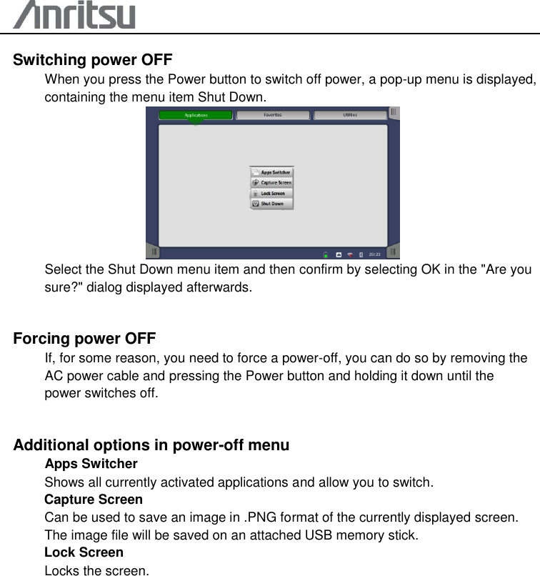
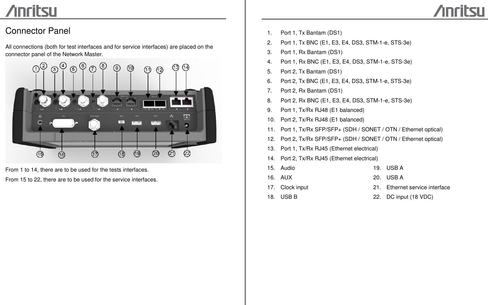
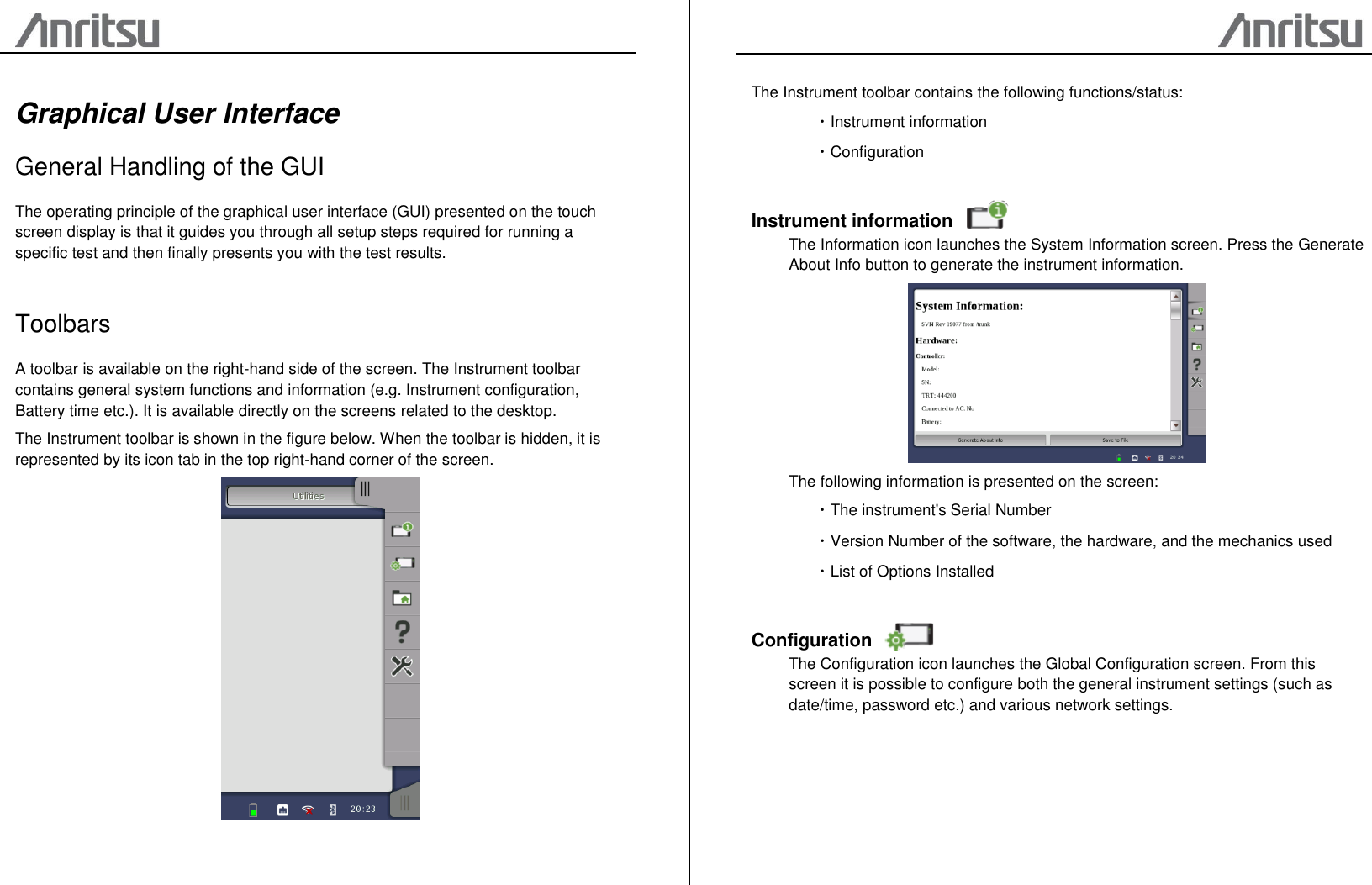
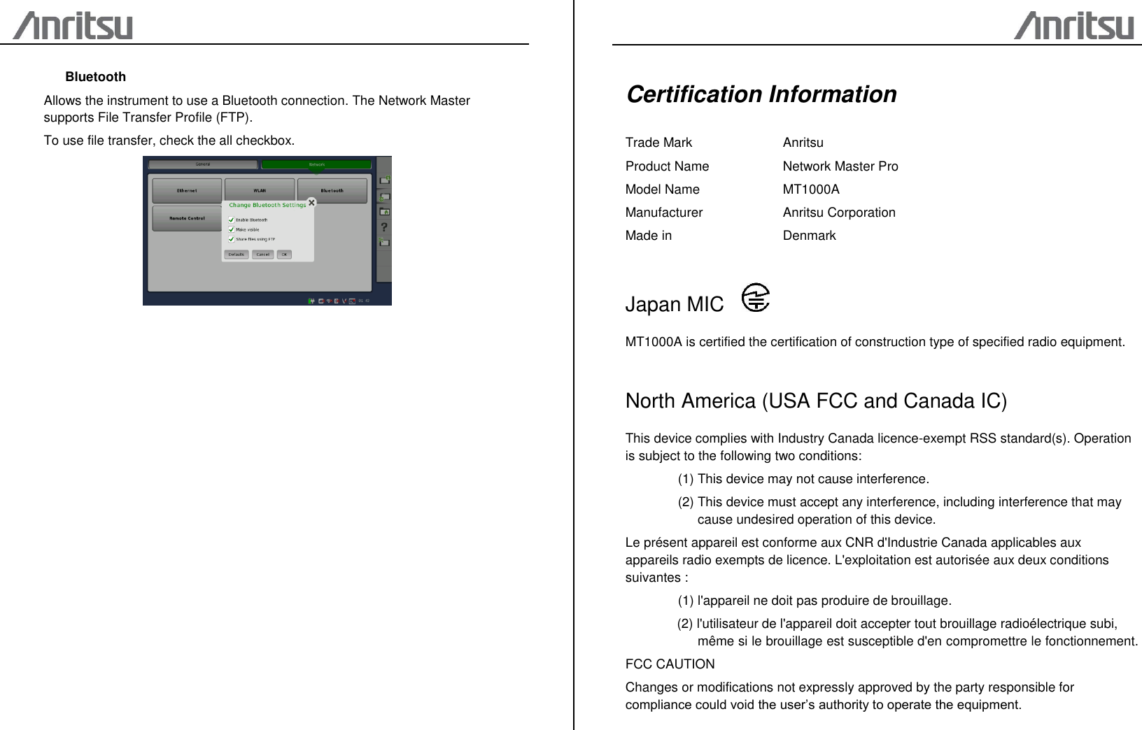
MT1000A User Manual
(Short Term Conficential) User Manual
Navigation menu
Upload a User Manual
Namespaces
Wiki Guide
HTML
PDF
Info
Views
User Manual
Discussion / Help
Navigation