Anritsu MT1100A Network Master Flex User Manual Short Term Confidential Rev
Anritsu Corporation Network Master Flex Short Term Confidential Rev
Anritsu >
(Short-Term Confidential) User Manual-Rev
MT1100A
Network Master Flex
User’s Manual
for WLAN/BT function
First Edition
ANRITSU CORPORATION
Introduction
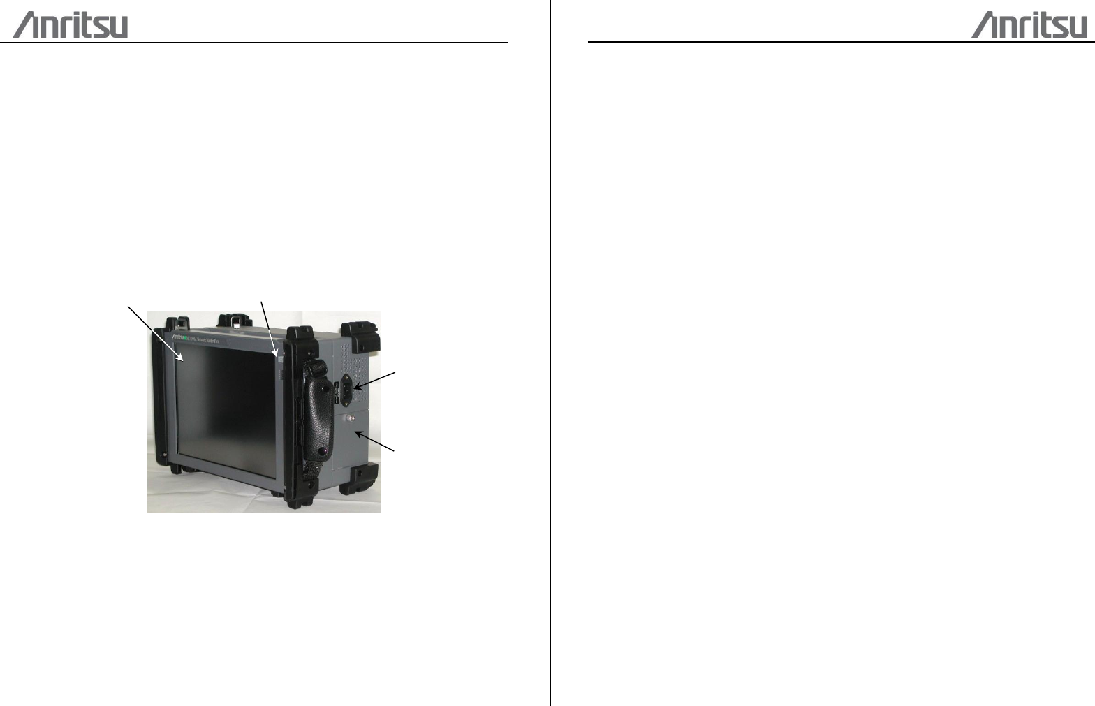
Mainframe (MT1100A)
The MT1100A Network Master Flex is a multipurpose telecommunications test
instrument up to 100 Gbit/s for field use. The installed options enable the Network
Master to be used both as a full-featured transmission line quality tester and as an
advanced signaling analyzer.
Results are easily read from the large color LCD display, where the colors and
graphical symbols facilitate interpretation. Together with the touch screen operation,
this makes the Network Master very user-friendly in operation. The instrument has the
following interface for data transfer and external communication: LAN interface
(Wired/Wireless), Bluetooth® interface and three USB ports.
The instrument is powered by the MU110001A/MU110002A power supply module unit.
Power Button
Inlet
Touch Screen
Battery
Safety
Overvoltage Category
This equipment complies with overvoltage category II defined in IEC 61010. DO NOT
connect this equipment to the power supply of overvoltage category III or IV.
Repair
Only qualified service personnel with a knowledge of electrical fire and shock hazards
should service this equipment. This equipment cannot be repaired by the operator. DO
NOT attempt to remove the equipment covers or unit covers or to disassemble internal
components. In addition, there is a risk of damage to precision components.
Battery
When replacing the battery, use the specified battery and insert it with the correct
polarity. If the wrong battery is used, or if the battery is inserted with reversed polarity,
there is a risk of explosion causing severe injury or death.
DO NOT expose batteries to heat or fire. Do not expose batteries to fire. This is
dangerous and can result in explosions or fire. Heating batteries may cause them to
leak or explode.
LCD
This equipment uses a Liquid Crystal Display (LCD). DO NOT subject the equipment to
excessive force or drop it. If the LCD is subjected to strong mechanical shock, it may
break and liquid may leak. This liquid is very caustic and poisonous.DO NOT touch it,
ingest it, or get in your eyes. If it is ingested accidentally, spit it out immediately, rinse
your mouth with water and seek medical help. If it enters your eyes accidentally, do not
rub your eyes, rinse them with clean running water and seek medical help. If the liquid
gets on your skin or clothes, wash it off carefully and thoroughly.
External Storage
This equipment uses a USB memory as external storage media for storing data and
programs. If this media is mishandled or becomes faulty, important data may be lost. To
prevent this chance occurrence, all important data and programs should be backed-up.
Anritsu will not be held responsible for lost data.
Use in Residential Environment
This equipment is designed for an industrial environment. In a residential environment,
this equipment may cause radio interference in which case the user may be required to
take adequate measures.
This equipment is also used more than 20cm away from the human body.
Use in Corrosive Atmospheres
Exposure to corrosive gases such as hydrogen sulfide, sulfurous acid, and hydrogen
chloride will cause faults and failures.
Note that some organic solvents release corrosive gases.
Configuration
This chapter contains information about the basic configuration.
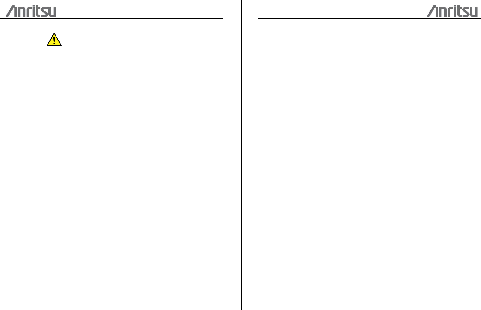
Rechargeable Battery
The Network Master is delivered with a 14.4 V Intelligent Li-Ion rechargeable and
replaceable battery.
Use only original batteries delivered from Anritsu, to prevent the risk of
instrument damage or personal injury. Battery should only be charged at room
temperature.
To install or replace the battery in the Network Master, follow the procedure below:
1. Disconnect the power cable if it is connected.
2. Switch the Network Master OFF.
3. Place the instrument on its back on a plain surface and loosen the lock
screw of the battery compartment.
4. Remove the lid of the battery compartment.
5. Pull out the battery from the compartment.
6. When installing the battery, note the direction of the battery terminals.
With the instrument placed on its back - and the battery compartment in
front of you - the terminals should be in the upper left corner.
7. Re-install the battery compartment door and tighten the lock screw.
Cables
Cables are connected to the input and output connectors located on the connector
panel of the instrument. When connecting the Network Master to the line, it is
recommended always to use shielded cables of good quality.
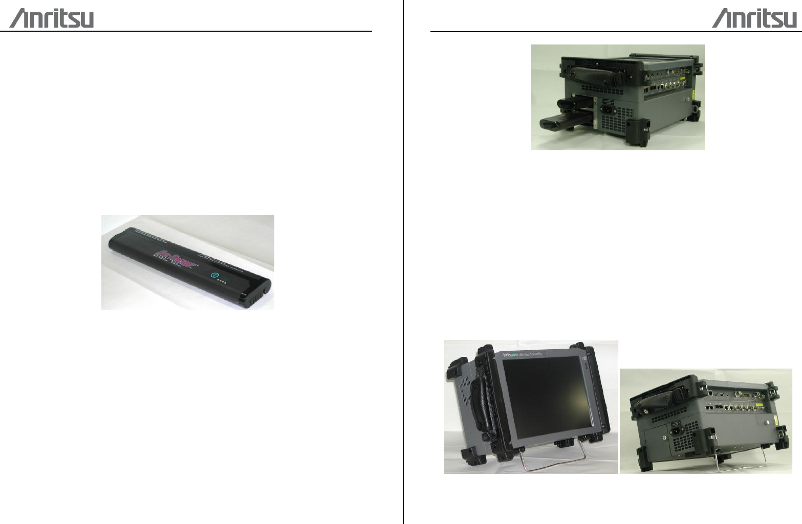
Support Stand
The Network Master is equipped with a support stand keeping the instrument at a
convenient angle during the operation. To extract the stand: pull out the
metal bar on rear of the instrument - it automatically stays in the correct position.
Carrying Strap and Handle
The included carrying strap can easily be mounted for your convenience when
transporting and/or using the Network Master.
The carrying strap is equipped with hooks for easy installation.
Use the Carrying Strap around your sholder. Do not wrap the strap around your
neck.
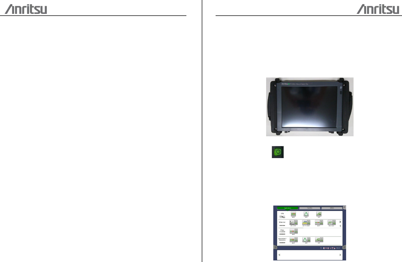
Man-Machine-Interface
Touch Screen Display
The 12.1 inch active TFT display with SVGA resolution (800x600 pixels) is used for
setups and for presentation of results. As the display includes touch screen functionality,
it is possible to navigate and operate directly from it.
Power Button
The only physical operator key is the Power button. The Power button on the front
panel of the instrument is used to switch power ON and OFF. In addition, the menu
used for power-off also contains a few extra options (e.g. to lock the screen).
Switching power ON
When you press the Power button to switch on power, the TFT display presents
you with a startup screen where you can select the application you want to use.
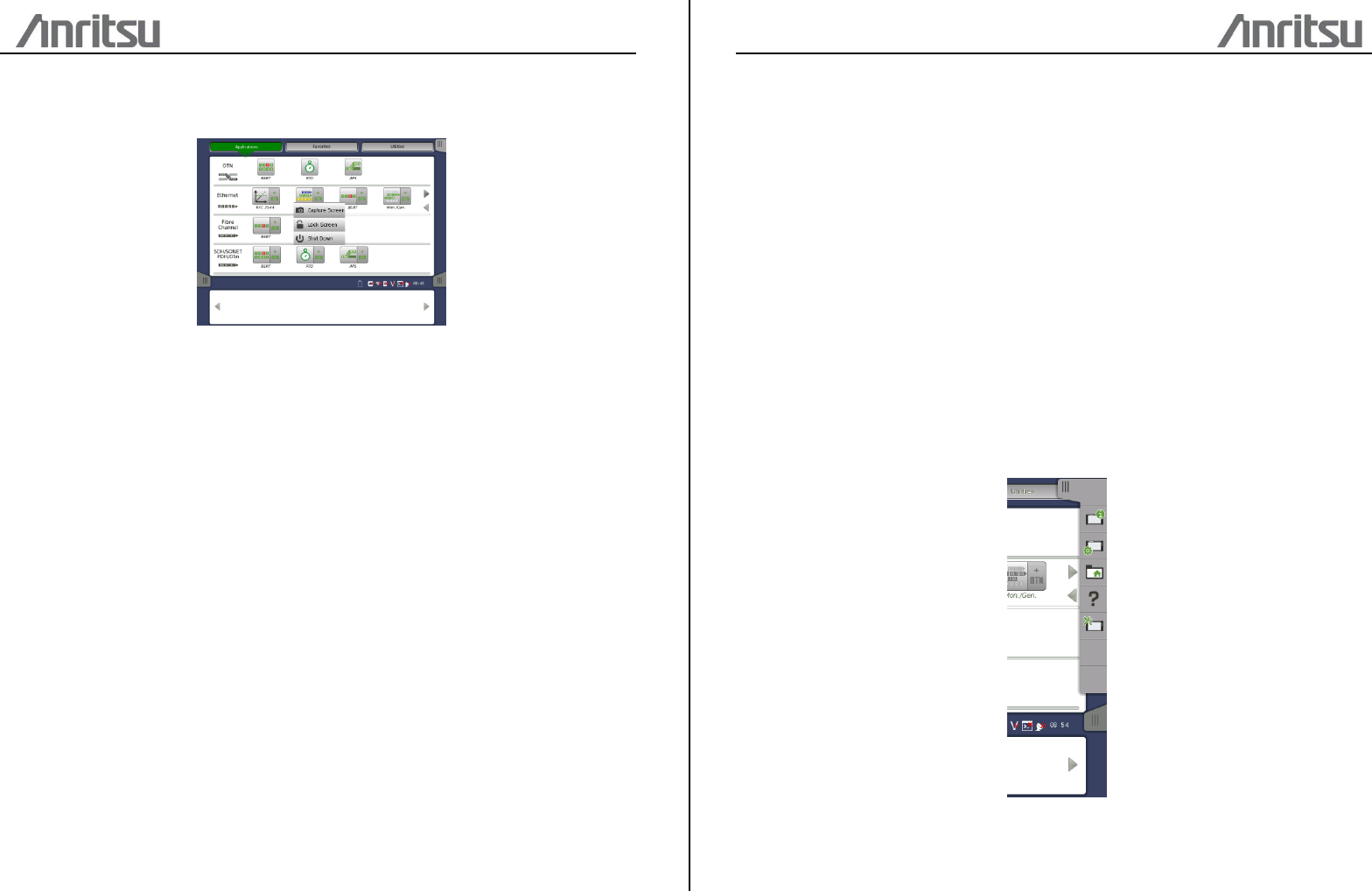
Switching power OFF
When you press the Power button to switch off power, a pop-up menu is displayed,
containing the menu item Shut Down.
Select the Shut Down menu item and then confirm by selecting OK in the "Are you
sure?" dialog displayed afterwards.
Forcing power OFF
If, for some reason, you need to force a power-off, you can do so by removing the
AC power cable and pressing the Power button and holding it down until the
power switches off.
Additional options in power button menu
Capture Screen
Can be used to save an image in .PNG format of the currently displayed screen.
The image file will be saved on an attached USB memory stick.
Lock Screen
Locks the screen.
Graphical User Interface
General Handling of the GUI
The operating principle of the graphical user interface (GUI) presented on the touch
screen display is that it guides you through all setup steps required for running a
specific test and then finally presents you with the test results.
Toolbars
A toolbar is available on the right-hand side of the screen. The Instrument toolbar
contains general system functions and information (e.g. Instrument configuration,
Battery time etc.). It is available directly on the screens related to the desktop.
The Instrument toolbar is shown in the figure below. When the toolbar is hidden, it is
represented by its icon tab in the top right-hand corner of the screen.
The Instrument toolbar contains the following functions/status:
・Instrument information
・Configuration
・File manager
・Help
・Resource monitoring
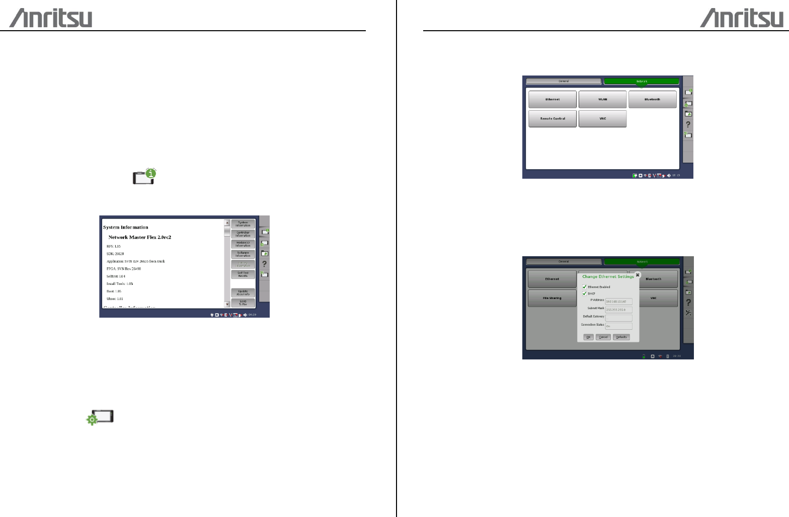
Instrument information
The Information icon launches the System Information screen. Press the Generate
About Info button to generate the instrument information.
The following information is presented on the screen:
・The instrument's Serial Number
・Version Number of the software, the hardware, and the mechanics used
・List of Options Installed
Configuration
The Configuration icon launches the Global Configuration screen. From this
screen it is possible to configure both the general instrument settings (such as
date/time, password etc.) and various network settings.
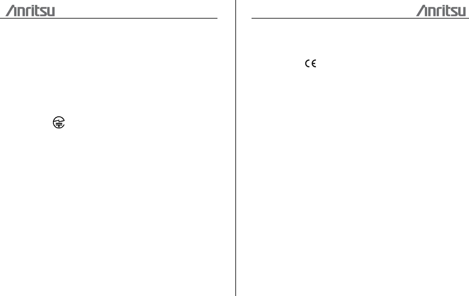
The Network tab contains the following configuration options for the instrument's
network connection:
Ethernet
Allows the instrument to be connected to the Ethernet either via dynamic
addressing (DHCP) or via manual specification of IP address, subnet mask and
default gateway.
WLAN
Allows the instrument to connect to a network via Wireless Local Area Network
(WLAN). Note that if WLAN is enabled, the instrument cannot connect to the
Ethernet via the Ethernet setting mentioned above.
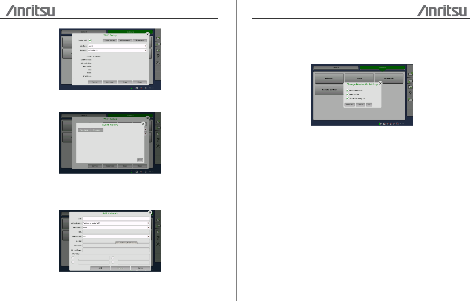
Press the Event History button to display a list of recent events.
To add a network, press the Add Network button. To edit the settings of the
current network, press the Edit Network button. In both cases, the NetworkConfig
dialog is launched.
Bluetooth
Allows the instrument to use a Bluetooth connection. The Network Master
supports File Transfer Profile (FTP).
To use file transfer, check the all checkbox.
Certification Information
Trade Mark Anritsu
Product Name Network Master Flex
Model Name MT1100A
Manufacturer Anritsu Corporation
Made in Japan
Japan MIC
MT1100A is certified the certification of construction type of specified radio equipment.
North America (USA FCC and Canada IC)
This device complies with Industry Canada licence-exempt RSS standard(s). Operation
is subject to the following two conditions:
(1) This device may not cause interference.
(2) This device must accept any interference, including interference that may
cause undesired operation of this device.
Le présent appareil est conforme aux CNR d'Industrie Canada applicables aux
appareils radio exempts de licence. L'exploitation est autorisée aux deux conditions
suivantes :
(1) l'appareil ne doit pas produire de brouillage.
(2) l'utilisateur de l'appareil doit accepter tout brouillage radioélectrique subi,
même si le brouillage est susceptible d'en compromettre le fonctionnement.
FCC CAUTION
Changes or modifications not expressly approved by the party responsible for
compliance could void the user’s authority to operate the equipment.
This transmitter must not be co-located or operated in conjunction with any other
antenna or transmitter.
Europe CE
Hereby, Anritsu Corporation, declares that this instrument is in compliance with the
essential requirements and other relevant provisions of Directive 1999/5/EC.
Support
This chapter contains information about general maintenance of the Network Master. It
also contains information about how to obtain support or service assistance.
Service and Repair
There are no user-serviceable parts in the Network Master. Possible service or repair
should be performed by Anritsu authorized personnel only. Please contact your local
Anritsu representative to get support or service assistance.
Manufacture date
If you need to check the date of manufacture, you can check by looking the label
bottom of the instrument.
Specifications
External Interfaces
Internal Clock Accuracy STRATUM 3 compliant
Reference Clock Input Accuracy ITU-T G.703 compliant
(BITS, SETS, 2 MHz) Connector BNC Jack (Unbalanced)
Range +/- 100 ppm
Serial Interface Connector D-sub 15 pin connector
Peripheral Interface USB (A x 2, mini B x 1 Port, Revision 2.0)
RJ45 Ethernet (10/100/1000 BASE-T)
WLAN (2.4 GHz IEEE802.11b/g/n)
Bluetooth 2.1 + EDR
3.5 mm Audio Jack
Remote Control Ethernet
Other Interfaces
Input device Power switch, Touch panel
LCD 12.1 inch display with SVGA resolution (800x600 pixels)
LED On, Standby, Charge
Speaker Internal (monaural)
Environment Performance
Power Consumption max. 45 W
Temperature Range Operating: 0°C to +40°C (non-condensing)
Storage: -20°C to +60°C (non-condensing)
Humidity Operating: max. 80 % RH
Storage: max. 80 % RH
EMC EN61326-1, EN61000-3-2 and EN301 489-1/-17
Mechanical Performance
Size 267 (H) x 346 (W) x 55.5 (D) (Excluding projections)
Mass 2.5 kg max.
MT1100A
Network Master Flex
User’s Manual for WLAN/BT function
25 September 2014 (First Edition)
Copyright 2014, ANRITSU CORPORATION.
All rights reserved. No part of this manual may be reproduced without the prior written
permission of the publisher.
The contents of this manual may be changed without prior notice.
Anritsu Corporation
5-1-1 Onna, Atsugi-shi, Kanagawa,
243-8555, Japan