AnyDATA DT2000 CDMA Dual Band Data Module User Manual CDMA DATA TERMINAL
AnyDATA Corporation CDMA Dual Band Data Module CDMA DATA TERMINAL
UserManual.wiki
>
AnyDATA
>
DT2000 User Manual
>
updated users manual
Contents
1.
users manual
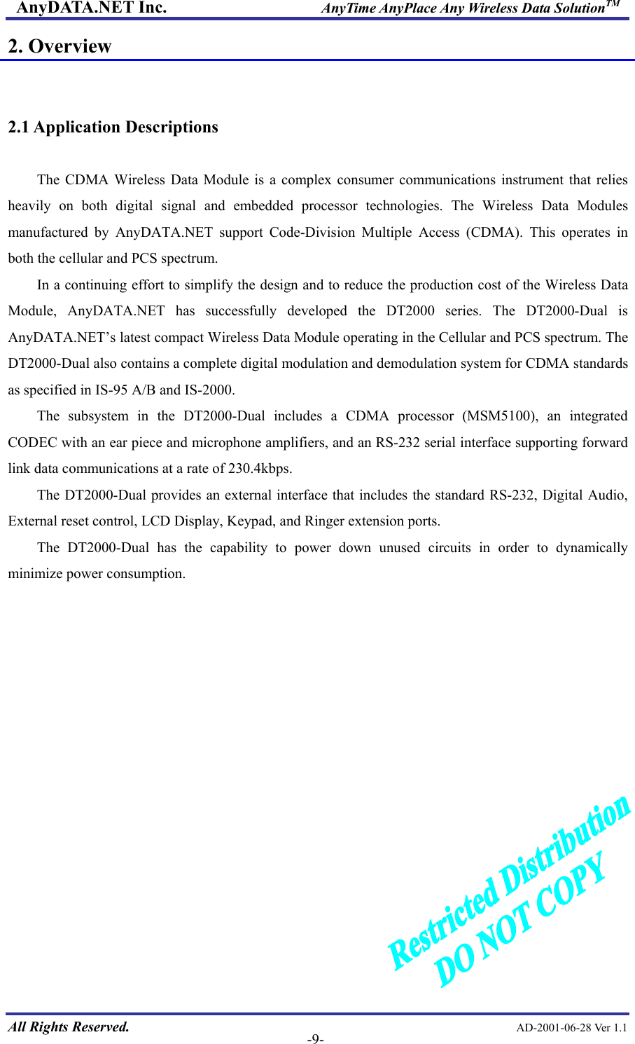
2.
updated users manual
updated users manual
Navigation menu
Upload a User Manual
Namespaces
Wiki Guide
HTML
PDF
Info
Views
User Manual
Discussion / Help
Navigation
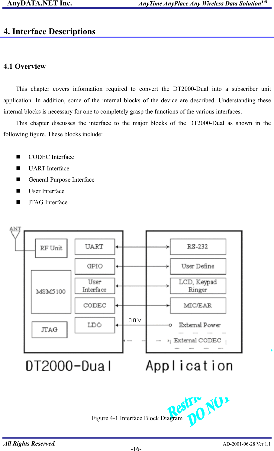
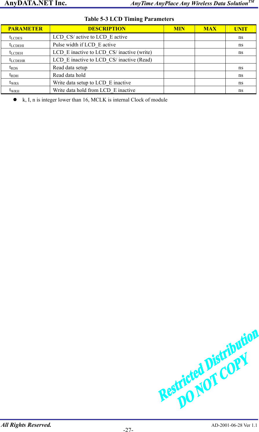
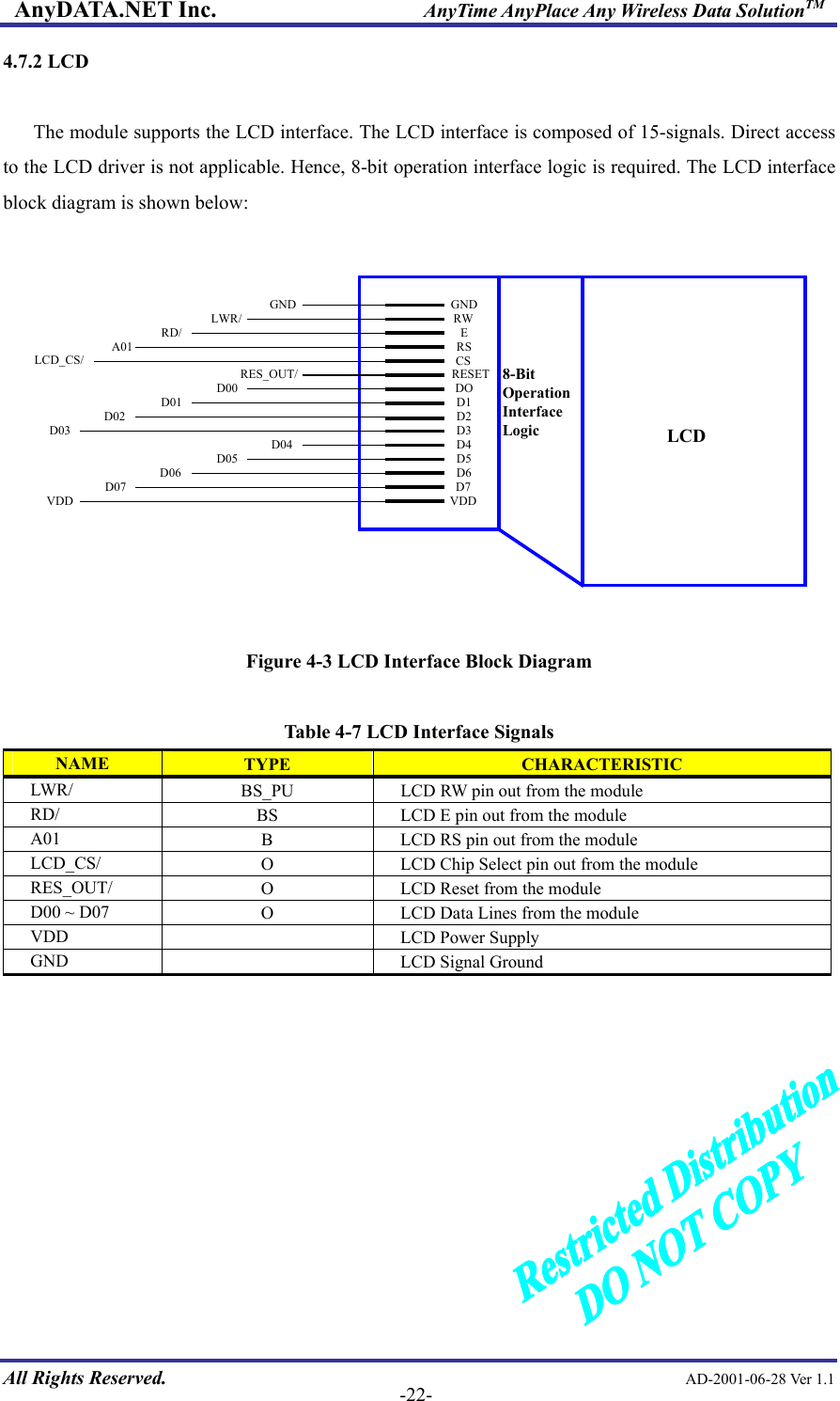
![AnyDATA.NET Inc. AnyTime AnyPlace Any Wireless Data SolutionTM 4.7 User Interface 4.7.1 Keypad The keypad interface consists of a 4 X 5 matrix pattern. Only 4 of the 5-KEYSENSE/[4:0] pins are used to connect a matrix keypad to the module. The KEYSENSE/ pins are active low. 5-GPIO pins are necessary to construct the other side of the matrix. These 5-GPIO pins must be active high in order for the keypad matrix to work properly. The general keypad matrix is shown below: #KEYSENSE0/KEYSENSE1/KEYSENSE2/KEYSENSE3/1-GPIO2-GPIO3-GPIO4-GPIO5-GPIO9630852*741SENDENDReserved Figure 4-2 Keypad Matrix All Rights Reserved. AD-2001-06-28 Ver 1.1 -21-](https://usermanual.wiki/AnyDATA/DT2000.updated-users-manual/User-Guide-413655-Page-21.png)
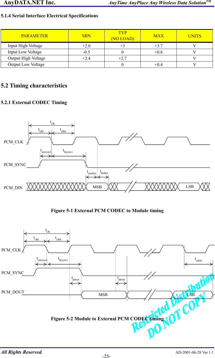
![AnyDATA.NET Inc. AnyTime AnyPlace Any Wireless Data SolutionTM Table 5-2 External PCM CODEC Parameters PARAMETER DESCRIPTION MIN TYP. MAX UNITtclk PCM-CLK cycle time 400 500 ns tclkl PCM-CLK low time 200 250 ns tclkh PCM-CLK high time 200 250 ns tsu(sync) PCM_SYNC setup time to PCM_CLK falling 150 ns th(sync) PCM_SYNC hold time after PCM_CLK falling 350 ns tsu(din) PCM_DIN setup time to PCM_CLK falling 50 ns th(din) PCM_DIN hold time after PCM_CLK falling 10 ns tpdout Delay from PCM_CLK falling to PCM_DOUT 50 ns 5.2.2 LCD Timing tWRSMCLK(modem)A[21:0]LWR/WriteData[7:0]LCD_CS/RD/LCD_EReadData[7:0]TtWRHtLCDEStLCDEHItLCDEHtRDStRDHLCD Data WriteLCD Data Read Figure 5-3 LCD Timing All Rights Reserved. AD-2001-06-28 Ver 1.1 -26-](https://usermanual.wiki/AnyDATA/DT2000.updated-users-manual/User-Guide-413655-Page-26.png)