AnyDATA DTSS-800 CDMA Data Modem with DTSS-800 User Manual EMII800 user manual
AnyDATA Corporation CDMA Data Modem with DTSS-800 EMII800 user manual
AnyDATA >
Users Manual

EMII-800 V1.0 AnyDATA.NET Proprietary Use Subject to Restrictions
EMII-800 User Manual
Application Information
EMII-800-V1.0
February 15, 2002
AnyDATA.NET Inc.
Hanvit Bank B/D 6F
Byulyang-dong Kwachon
KOREA
Tel) 82-2-504-3360
Fax) 82-2-504-3362

Interface Description EMII-800 Reference Manual Application Information
EMII-800 V1.0 AnyDATA.NET Proprietary Use Subject to Restrictions
AnyDATA.NET Inc.
Hanvit Bank B/D 6F
Byulyang-dong Kwachon
KOREA
Copyright ℃ 2001 AnyDATA.NET Inc..
All rights reserved. Printed in the Republic Of KOREA.
All data and information contained in or disclosed by this document are confidential and proprietary
information of AnyDATA.NET Inc., and all rights therein are expressly reserved. By accepting this
material, the recipient agrees that this material and the information contained therein are held in
confidence and in trust and will not be used, copied, reproduced in whole or in part, nor its contents
revealed in any manner to others without the express written permission of AnyDATA.NET Inc..
AnyDATA.NET Proprietary : Restricted Distribution. This document contains critical information about
AnyDATA.NET products and may not be distributed to anyone without permission of AnyDATA.NET
Inc. All data and information contained in this document are proprietary and confidential information of
AnyDATA.NET Inc. No part of this document may be reproduced, in any form or any means without
written permission of AnyDATA.NET Inc.
Although the information in this document has been carefully reviewed and its believed to be reliable.
AnyDATA.NET Inc. does not assume any liability arising out of the application or use of any product
described herein, Neither does it convey any license under its patent rights nor rights of others.
Send Technical Questions to :
paiton@AnyDATA.NET
EMII-800 User Manual Application Information
EMII-800-V1.0
February 15, 2002
Interface Description EMII-800 Reference Manual Application Information
EMII-800 V1.0 AnyDATA.NET Proprietary Use Subject to Restrictions
Introduction
The EMII-800 is designed for the test and simulation of the CDMA wireless data
communications. User can connect the EMII-800 to your PC or Notebook and easily test the wireless
communications. User can use this to develop your applications software even before user–s own
hardware is ready. It also can be used as a debugging during user–s hardware test.
Disclaimer and Limitation of Liability
AnyDATA.NET Inc. assumes no responsibility for any damage or loss resulting from the misuse of its
products. AnyDATA.NET Inc. assumes no responsibility for any loss or claims by third parties, which
may arise through the use of its products.
AnyDATA.NET Inc. assumes no responsibility for any damage or loss caused by the deletion or loss of
data as a result of malfunctions or repairs.
The information disclosed herein is the exclusive property of AnyDATA.NET Inc. and no part of this
publication may be reproduced or transmitted in any form or by any means including electronic storage,
reproduction, execution or transmission without the prior written consent of AnyDATA.NET Inc. The
information contained in this document is subject to change without notice.
Reproduction, adaptation or translation of this document is prohibited without prior written permission of
AnyDATA.NET Inc.
FCC RF Exposure Information
Warning! Read this information before using this device.
In August 1996 the Federal Communications Commission (FCC) of the United States
with its action in Report and Order FCC 96-326 adopted an updated safety standard for human
exposure to radio frequency electromagnetic energy emitted by FCC regulated transmitters. Those
guidelines are consistent with the safety standard previously set by both U.S. and international
standards bodies. The design of this device complies with the FCC guidelines and these
international standards.
Interface Description EMII-800 Reference Manual Application Information
EMII-800 V1.0 AnyDATA.NET Proprietary Use Subject to Restrictions
CAUTION
n Operating Requirements
The user can not make any changes or modifications not expressly approved by the party
responsible for compliance, otherwise it could void the user's authority to operate the equipment.
To satisfy FCC RF exposure compliance requirements for a mobile transmitting device, this
device and its antenna should generally maintain a separation distance of 20cm or more from a
person–s body.
Special accessories
In order to ensure this device in compliance with FCC regulation, the special accessories are provided
with this device and must be used with the device only. The user is not allowed to use any other
accessories than the special accessories given with this device

Interface Description EMII-800 Reference Manual Application Information
EMII-800 V1.0 AnyDATA.NET Proprietary Use Subject to Restrictions
Contents
1 Introduction
1.1 Purpose
1.2 Organization
1.3 Revision History
2 Overview
2.1 Application Description
2.2 Technical Specifications
2.2.1 General Specification
2.2.2 Receive Specification
2.2.3 Transmit Specification
2.2.4 Standards
2.3 Interface Diagram
2.4 EMII-800 General Features
2.5 Internal Modem Features
3 PIN Description
3.1 8-Pin Connector (RS232 Standard)
3.2 8-Pin Connector (Debugging)
3.3 DC Power Connector
4 Interface Descriptions
4.1 Overview
4.2 RS232 Interface (Standard)

Interface Description EMII-800 Reference Manual Application Information
EMII-800 V1.0 AnyDATA.NET Proprietary Use Subject to Restrictions
5 Electrical Specifications
5.1 Absolute Maximum Ratings
5.2 Recommended Operating Conditions
5.3 Power Consumption
5.4 Serial Interface Electrical Specifications
6 Mechanical Dimension
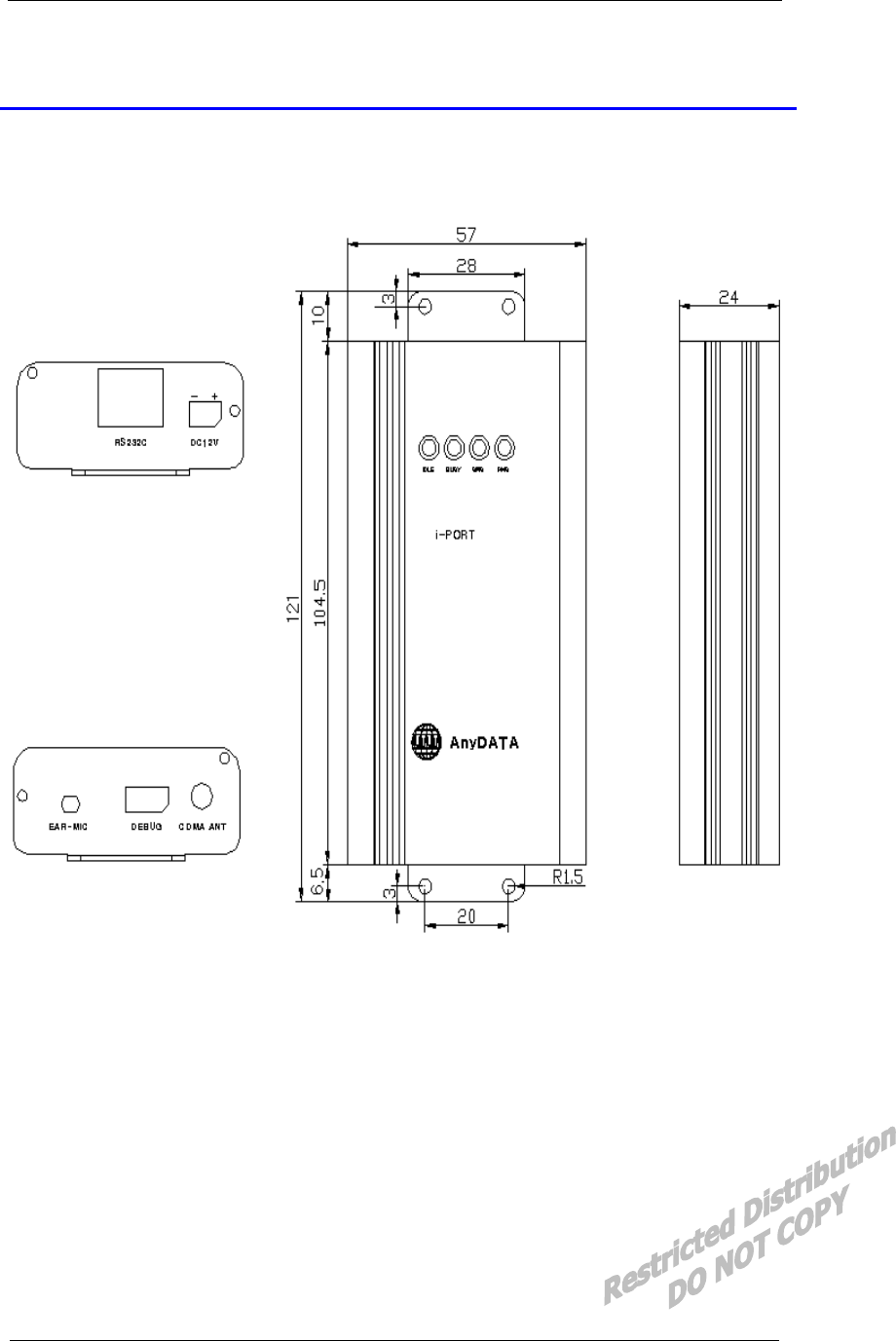
6.1 EMII-800 Outline
7 FCC Notice
Interface Description EMII-800 Reference Manual Application Information
EMII-800 V1.0 AnyDATA.NET Proprietary Use Subject to Restrictions
1. Introduction
1.1 Purpose
This Manual provides hardware interface and programming information for EMII-800 CDMA
Wireless Data Modem.
1.2 Organization
The interface and operation section is organized into the following subsections:
n Section 2 º Introduces users to the EMII-800 CDMA Wireless Data Modem basic features and
general specifications.
n Section 3 º Contains EMII-800 Pin description - DC12V Input Port, 8pin Serial Port and
Debugging Port.
n Section 4 º Describes the UART Interface.
n Section 5 º Specifies the recommended operating conditions, DC voltage characteristics, I/O
timing, and power estimations for the modem.
n Section 6 º Provides package dimensions and outlook features for the modem.
n Section 7 º Describes the FCC Notice.
1.3 Revision History
The revision history for this document is shown in Table 1-1.
Table 1-1 Revision History
Version
Date Description
V1.0 Feb. 2002 Initial Release

Interface Description EMII-800 Reference Manual Application Information
EMII-800 V1.0 AnyDATA.NET Proprietary Use Subject to Restrictions
2. Overview
2.1 Application Descriptions
The CDMA Wireless Data Modem is a complex consumer communications instrument that relies
heavily on both digital signal and embedded processor technologies. The Wireless Data Modem
manufactured by AnyDATA.NET supports Code-Division-Multiple-Access(CDMA). This operates in
PCS spectrum.
In a continuing effort to simplify the design and to reduce the production cost of the Wireless Data
Modem, AnyDATA.NET has successfully developed the EMII-800. The EMII-800 is AnyDATA.NET–s
latest compact Wireless Data Modem operating in PCS spectrum, also contains complete digital
modulation and demodulation system for CDMA standards as specified in IS-95 A/B and IS-2000.
The subsystem within the EMII-800 includes a CDMA processor (MSM5100), an integrated
CODEC with an ear piece and microphone amplifiers, and an RS-232 serial interface supporting forward
link data communications of a rate of 153.6kbps.
The EMII-800 provides external interface. External interface includes the standard RS-232, Digital
Audio, and External On/Off control.
The EMII-800 has the capability to power down unused circuits in order to dynamically minimize
power consumption.
Interface Description EMII-800 Reference Manual Application Information
EMII-800 V1.0 AnyDATA.NET Proprietary Use Subject to Restrictions
2.2 Technical Specifications
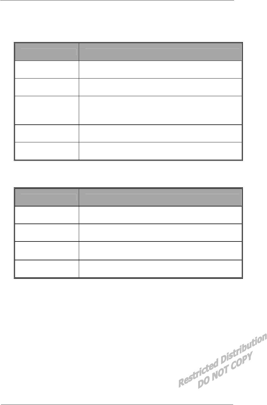
2.2.1 General Specifications
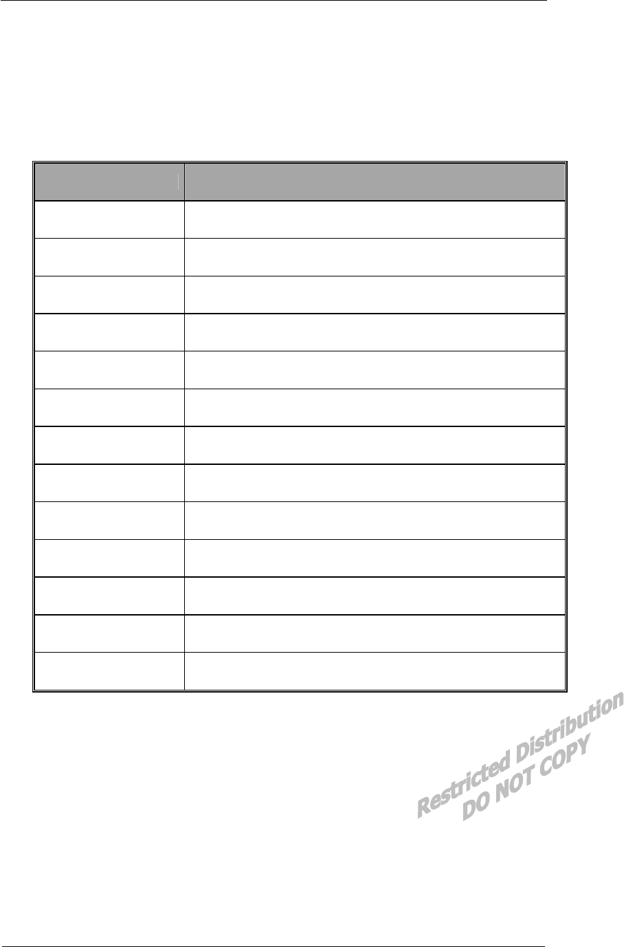
PARAMETERS DESCRIPTIONS
External Access Code-Division-Multiple-Access (CDMA)
CDMA Protocol IS-95A/B/C, IS-98A, IS-126, IS-637A, IS-707A
Data Rate 153.6Kbps
Transmit/Receive
Frequency Interval 45MHz
Band Width 1.23MHz
Operating Voltage DC 6V ~ 12V
Current Consumption Stand by mode : Idle (55mA) , Busy mode : 280mA (Max) at 12V
Operating Temperature -30± ~ +60±
Frequency Stability 䉢300Hz
Antenna Whip Antenna, 50ohm
Size 57 X 121 X 24mm with case
Weight About 112g
External Interface RS-232, Digital/Analog Audio, LCD, Keypad, Ringer
External On/Off Control
Interface Description EMII-800 Reference Manual Application Information
EMII-800 V1.0 AnyDATA.NET Proprietary Use Subject to Restrictions
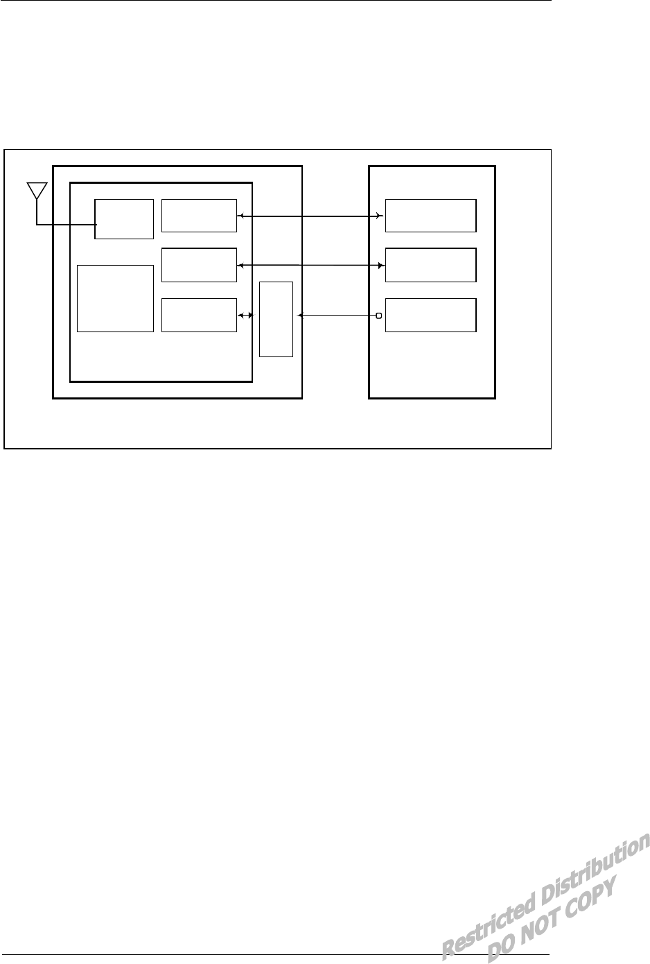
2.2.2 Receive Specifications
PARAMETERS DESCRIPTIONS
Frequency Range 869.04 ~ 893.97 MHz
Sensitivity Below º104 dBm
Interference
Rejection
Single tone (-30dBm @900KHz) : Below º101dBm
Two tone (-43 dBm @900KHz and 1700KHz) : Below º101dBm
Two tone (-32 dBm @900KHz and 1700KHz) : Below º90dBm
Two tone (-21 dBm @900KHz and 1700KHz) : Below º79dBm
Spurious Wave
Suppression Below º80dBc
Input Dynamic Range -25 dBm ~ -104dBm
2.2.3 Transmit Specifications
PARAMETERS DESCRIPTIONS
Frequency Range 824.04 ~ 848.97 MHz
Nominal Power 0.32 W
Minimum Controlled
Output Power Below º50dBm
Max Power Spurious Below º42dBc/30KHz @ 900KHz
Below º54dBc/30KHz @ 1.98MHz
2.2.4 Standards
IS-95A/B/C : Protocol Between MS & BTS
IS-96A : Voice Signal Coding
IS-98A : Base MS Function
IS-126 : Voice Loop-Back
IS-637 : Short Message Service
IS-707 : Data Service
Interface Description EMII-800 Reference Manual Application Information
EMII-800 V1.0 AnyDATA.NET Proprietary Use Subject to Restrictions
2.3 Interface Diagram
RF Unit
MSM5100
UART1
MSM Inter.
CODEC
LDO(12V)
RS-232
EARJACK
ANT
DTSS-800
Application Device
EMII-800
LDO(4V)
External PWR
(6~14V)
Figure 2-1 Interface Block Diagram
Interface Description EMII-800 Reference Manual Application Information
EMII-800 V1.0 AnyDATA.NET Proprietary Use Subject to Restrictions
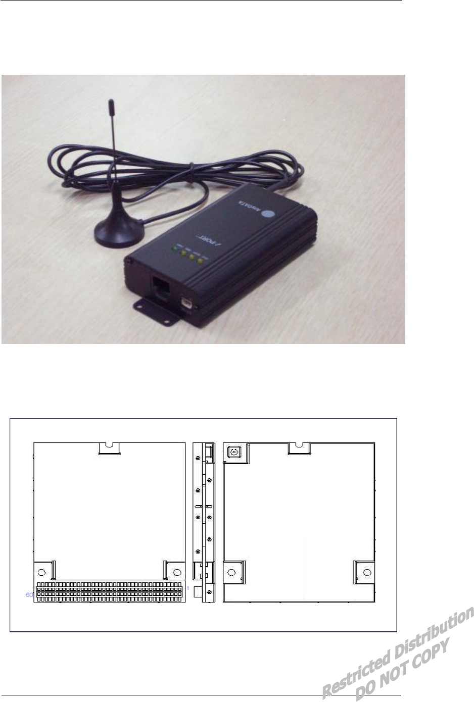
2.4 EMII-800 General Features
Figure 2-2 EMII-800General Features
2.5 Internal Modem Features
Figure 2-3 Internal Modem General Features (DTSS-800)
Interface Description EMII-800 Reference Manual Application Information
EMII-800 V1.0 AnyDATA.NET Proprietary Use Subject to Restrictions
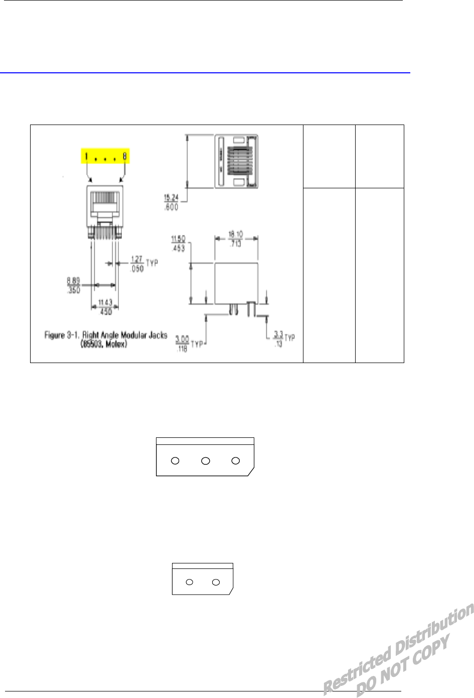
3. PIN Description
3.1 8-Pin Male Modular Jacks(RS232 Standard)
Molex
(85503)
RS-232
Pin 1
Pin 2
Pin 3
Pin 4
Pin 5
Pin 6
Pin 7
Pin 8
RI
GND
DTR
CTS
TX
RTS
RX
DCD
Figure 3-1 Right Angle Modular Jacks Pin Description (85503,Molex 8P)
3.2 3-Pin Connector (Debugging)
GND TXD RXD
Figure 3-2 Debugging Connector (5268,Molex 3P)
3.3 DC Power Connector
DC 12V
- +
Figure 3-3 DC 12V Power Connector (5268, Molex 2P)
Interface Description EMII-800 Reference Manual Application Information
EMII-800 V1.0 AnyDATA.NET Proprietary Use Subject to Restrictions
4. Interface Descriptions
4.1 Overview
This chapter covers information required to design the EMII-800 into a subscriber unit application.
In addition, the internal signals that are necessary for complete understanding of the UART interfaces are
described below.
4.2 RS232 Interface (Standard)
The Universal Asynchronous Receiver Transmitter (UART) communicates with serial data that
conforms the RS-232 Interface protocol. The modem provides 3.0V CMOS level outputs and 3.0V
CMOS switching input level. And all inputs have 5.0V tolerance but 3.0V or 3.3VCMOS logic
compatible signals are highly recommended.
All the control signals of the RS-232 signals are active low, but data signals of RXD, and TXD Are
active high. The UART has a 64byte transmit (TX) FIFO and a 64byte receive (RX) FIFO. The UART
Features hardware handshaking, programmable data sizes, programmable stop bits, and odd, even, no
parity. The UART operates at a 115.2kbps maximum bit rate.
NAME DESCRIPTION CHARACTERISTIC
DP_DCD/ Data Carrier Detect Network connected from the modem
DP_RI/ Ring Indicator Output to host indicating coming call
DP_RTS/ Request to Send Ready for receive from host
DP_TXD Transmit Data Output data from the modem
DP_DTR/ Data Terminal Ready Host ready signal
DP_RXD Receive Data Input data to the modem
DP_CTS/ Clear to Send Modem output signal
GND Signal Ground Signal ground
Figure 4-1 UART Interface Pinouts
Interface Description EMII-800 Reference Manual Application Information
EMII-800 V1.0 AnyDATA.NET Proprietary Use Subject to Restrictions
5. Electrical Specifications
5.1 Absolute Maximum Ratings
Operating the modem under conditions that exceed those listed in the Absolute Maximum. The
Ratings table may result in damage to the modem.
Absolute Maximum Ratings may be considered as limiting values, and are considered individually.
While all other parameters are within their specified operating ranges, the functional operation of the
modem under any of the conditions in the Absolute Maximum Ratings table is not implied.
Table 5-1 Absolute Maximum Ratings
PARAMETER MIN MAX UNITS
Storage Temperature -40 +100 C
Voltage On Any Input or Output Pin - +5.0 V
Supply Voltage - +15 V
Initializing Current 100 mA
Drop No damages after 60-Inch drop over concrete floor
5.2 Recommended Operating Conditions
PARAMETER MIN MAX UNITS
Supply Voltage 6 12 V
Operating Temperature -30 +60 C
Operating Humidity 95%(50C) Relative Humidity
5.3 Power Consumption
STANDBY
CONVERSATION Idle Sleep
280 mA (MAX) 55 mA 18 mA
5.4 Serial Interface Electrical Specifications
PARAMETER MIN MAX UNITS
Input High Voltage +2.0 +3.7 V
Input Low Voltage -0.5 +0.8 V
Output High Voltage +2.4 V
Output Low Voltage +0.4 V
Interface Description EMII-800 Reference Manual Application Information
EMII-800 V1.0 AnyDATA.NET Proprietary Use Subject to Restrictions
6. Mechanical Dimensions
6.1 EMII-800 Outline

Interface Description EMII-800 Reference Manual Application Information
EMII-800 V1.0 AnyDATA.NET Proprietary Use Subject to Restrictions
7. FCC Notice
This equipment has been tested and found to comply with the limits for a Class B digital device,
pursuant to part 15 of the FCC Rules. These limits are designed to provide reasonable protection
against harmful interference in a residential installation. This equipment generates, uses and can
radiate radio frequency energy and, if not installed and used in accordance with the instructions,
may cause harmful interference to radio communications. However, there is no guarantee that
interference will not occur in a particular installation. If this equipment does cause harmful
interference to radio or television reception, which can be determined by turning the equipment
off and on, the user is encouraged to try to correct the interference by one or more of the
following measures:
n Reorient or relocate the receiving antenna.
n Increase the separation between the equipment and receiver.
n Connect the equipment into an outlet on a circuit different from that to which the receiver is
connected.
n Consult the dealer or an experienced radio/TV technician for help.