Anywave Communication Technologies MPTV 1 kW DTV ATSC Transmitter User Manual
Anywave Communication Technologies, Inc. 1 kW DTV ATSC Transmitter
UserManual.wiki
>
Anywave Communication Technologies
>
MPTV User Manual
User Manual
Navigation menu
Upload a User Manual
Namespaces
Wiki Guide
HTML
PDF
Info
Views
User Manual
Discussion / Help
Navigation


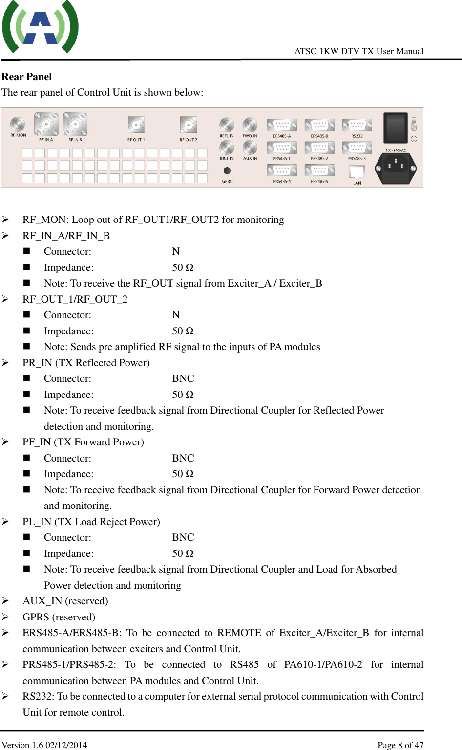
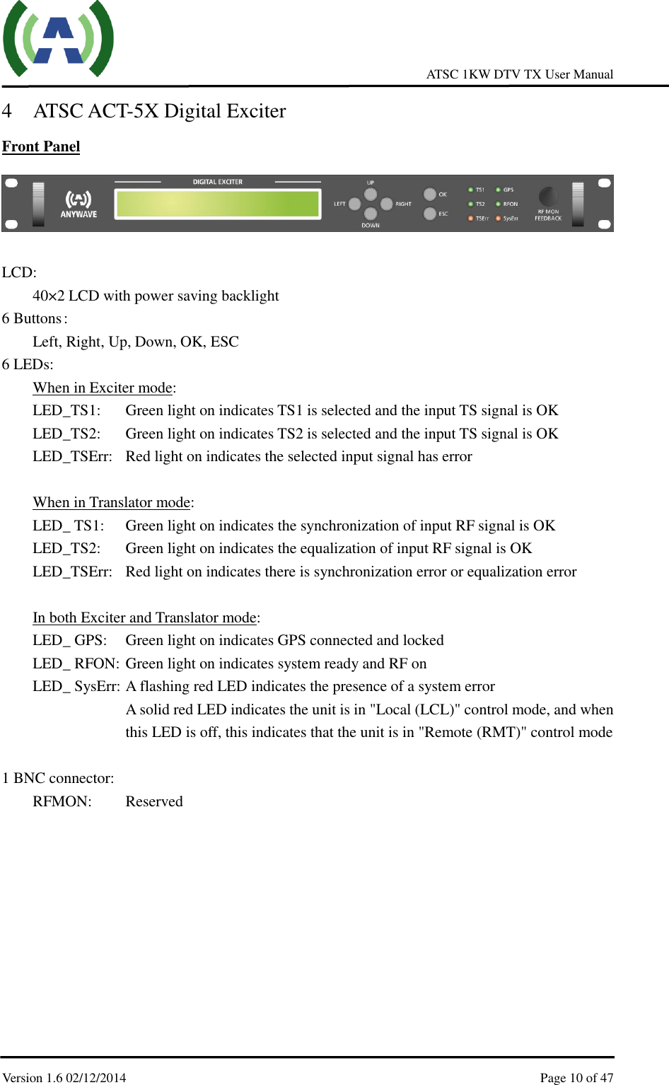
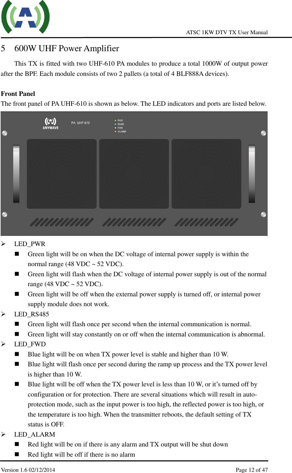
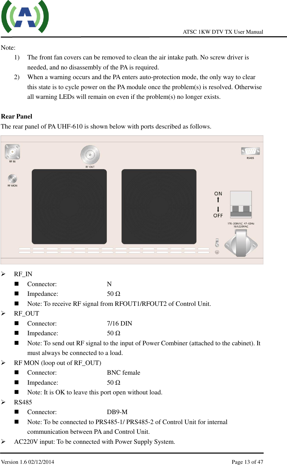
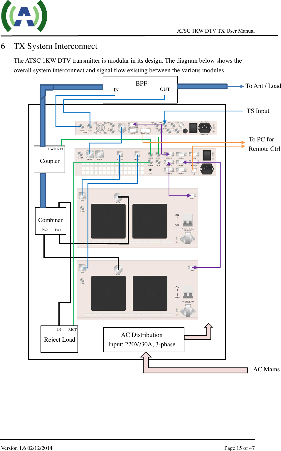
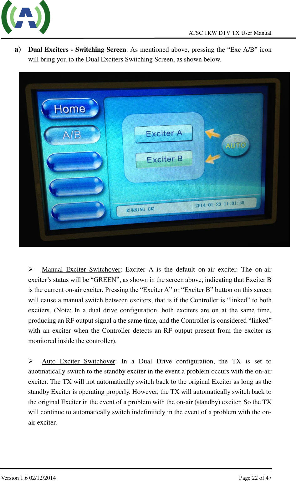
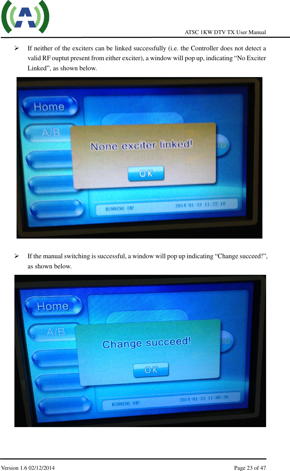
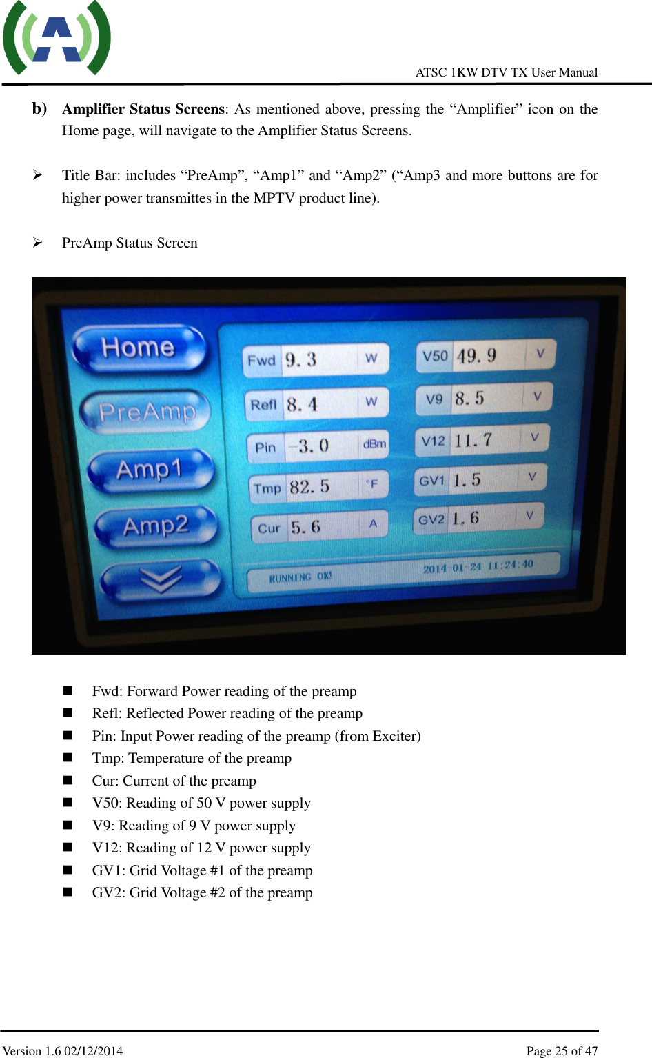
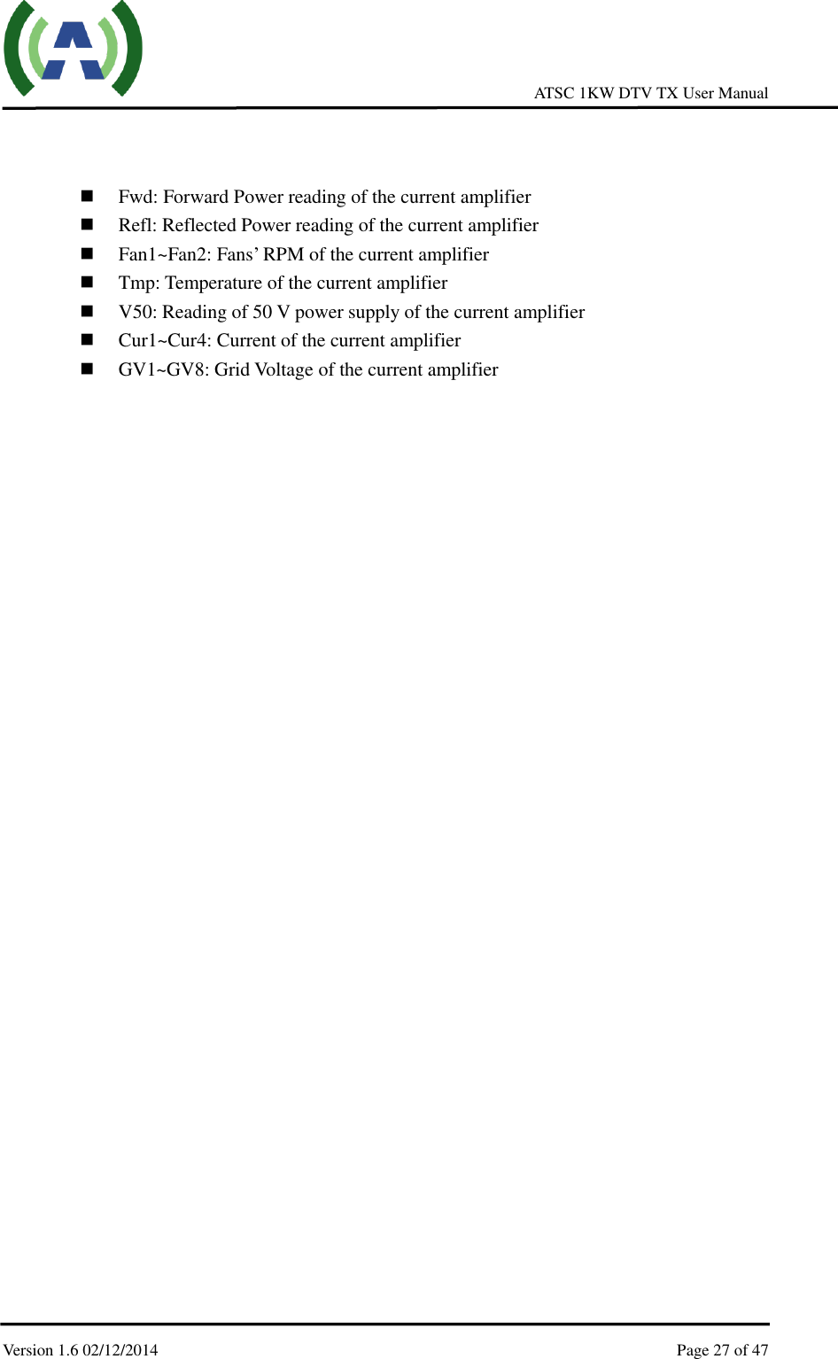
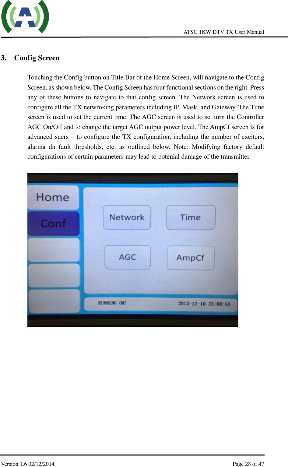
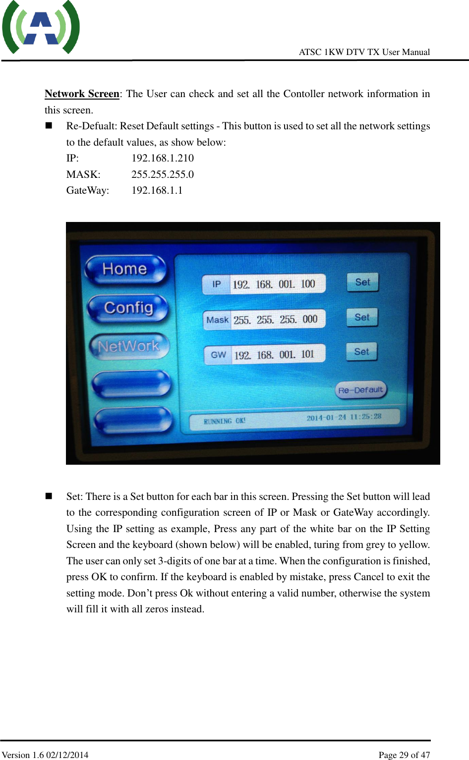
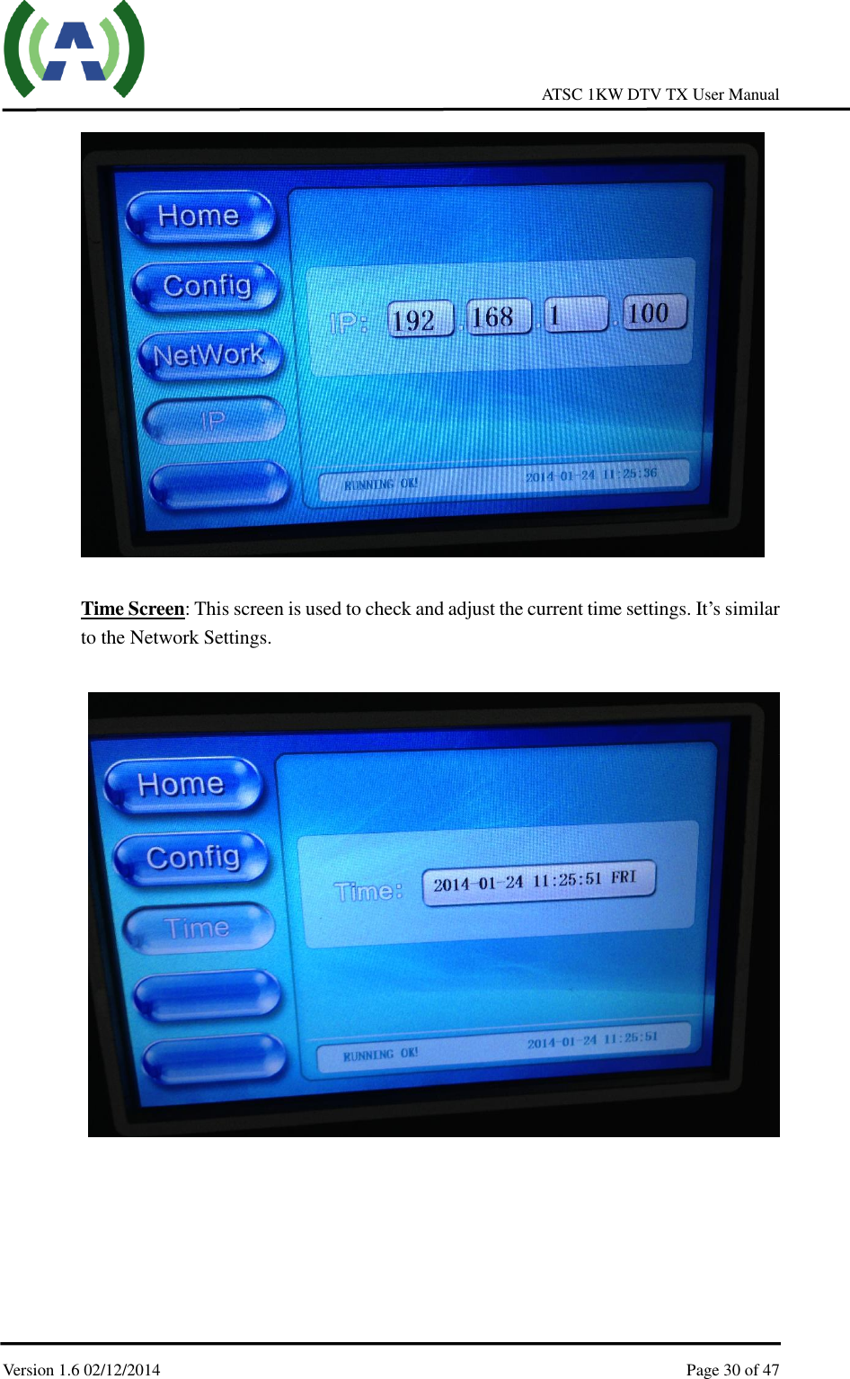
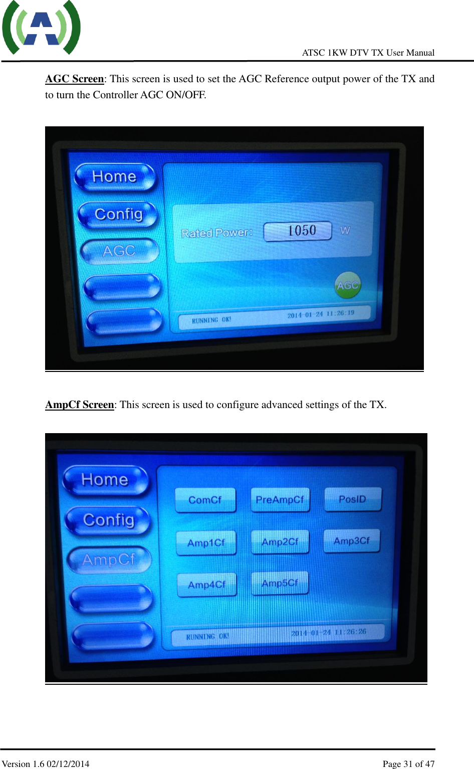
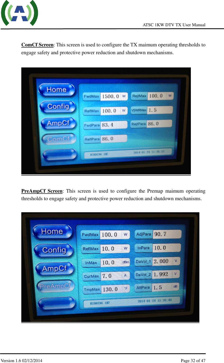
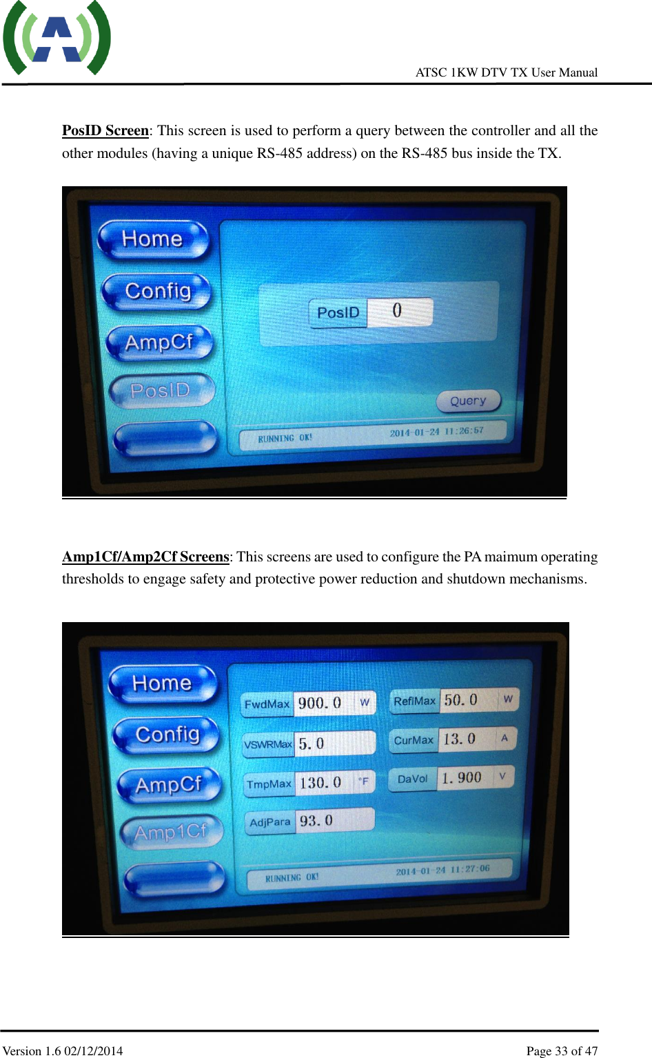
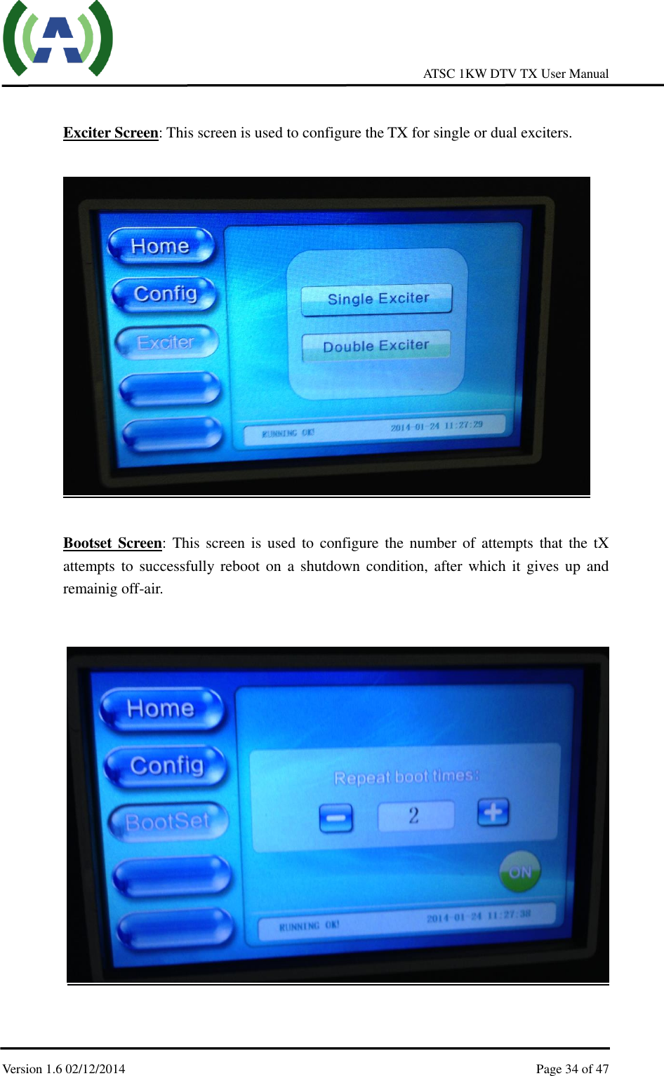
![ATSC 1KW DTV TX User Manual Version 1.6 02/12/2014 Page 11 of 47 Rear Panel RF_IN_A: Feedback signal, sampled after the band-pass filter (-5 to -15dBm) RF_IN_B: Feedback signal, sampled before the band-pass filter (-5 to -15dBm) AGC_IN: Feedback DC voltage for AGC control (0-5VDC) RF_MON: Loop out of RF_OUT for monitoring (-25 dB below RF_OUT) RF_OUT: Main RF signal output of exciter, to be connected to RF_IN_A/RF_IN_B of Control Unit (nominal 0 dBm output) DRYLOOP: Dry loop for remote control REMOTE: To be connected to ERS485-A/ERS485-B of Control Unit for internal communication between exciters and Control Unit REMOTE (RJ45-B): 10M/100M Ethernet for remote control (ipaddress: 192.168.1.143) TSoIP (RJ45-A): Reserved 10M_IN: 10 MHz input from external GPS receiver 1PPS_IN: 1 PPS input from external GPS receiver TS_IN_1: The first port of TS inputs, DVB-ASI only TS_OUT_1: Loop out of [TS_IN_1] for monitoring TS_IN_2: The second port of TS inputs, DVB-ASI only TS_OUT_2: Loop out of [TS_IN_2] for monitoring TUNER_IN: Received RF signal input Note: Please refer to the ACT-5X Exciter User Manual for more details of operations.](https://usermanual.wiki/Anywave-Communication-Technologies/MPTV/User-Guide-2225896-Page-11.png)