Aodee Electronic AODEE0AR257 Super Switch User Manual

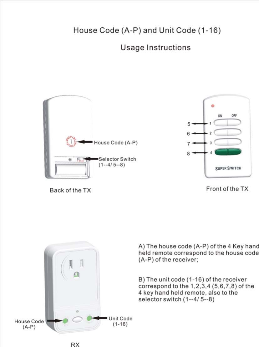
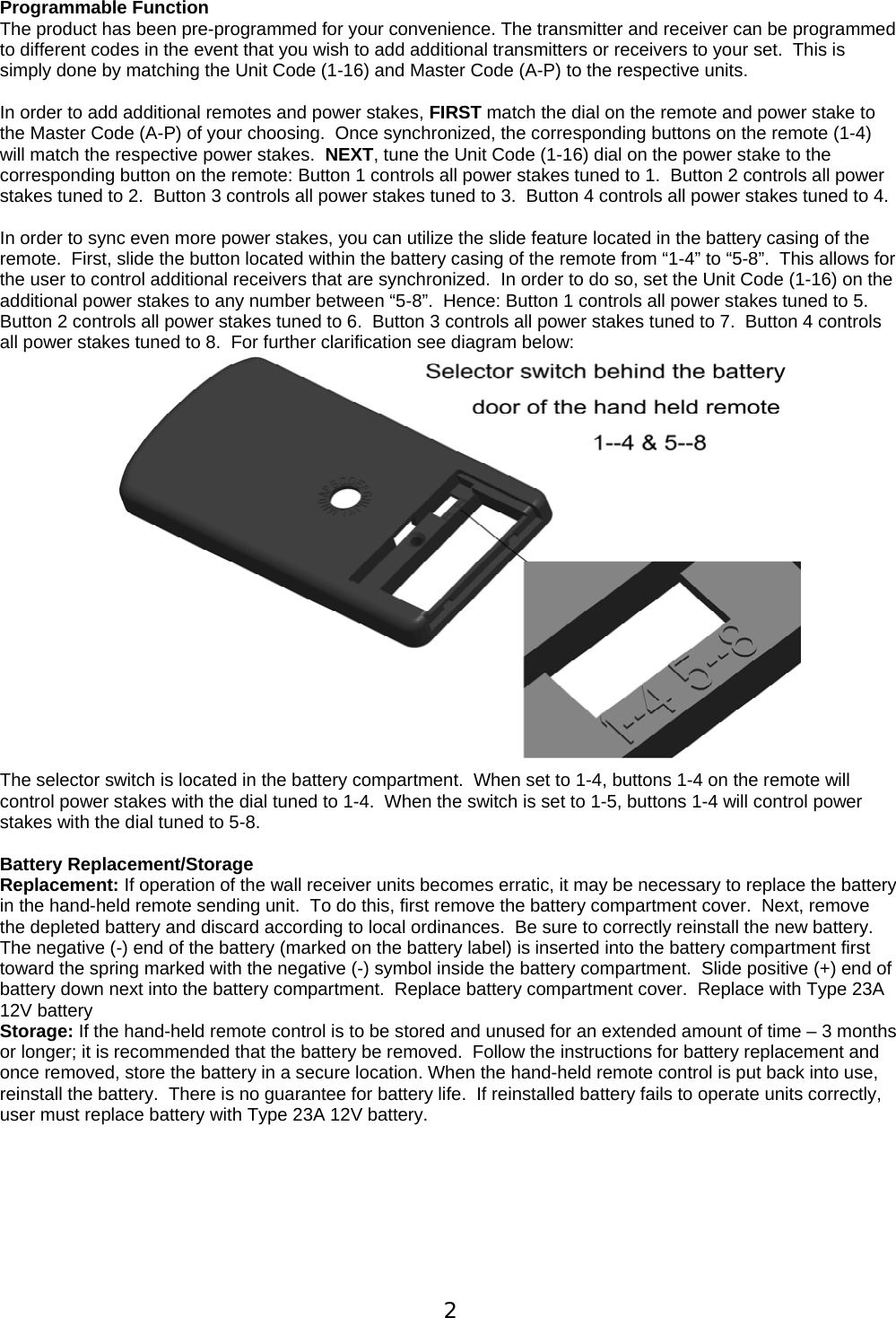
Shenzhen Aodee Electronic Co., Ltd. Super Switch

User Manual

 1 INDOOR SUPER SWITCH PRO Wireless Remote Control Wall Outlet  Set of 3 Indoor Outlets and Remote Control Package Includes: (3) Wireless Wall Outlet Receivers (Receiver Unit) (1) 4- Button Hand-Held Remote Control (Sender Unit) (1) 12V Type 23A battery  Features: The Super Switch operates on radio frequency and is not dependent on line of sight and will perform through walls, doors and floors up to 100 feet away.  No rewiring is required.   Operation: Remove Tape From Battery Chamber.   Remove battery cover on Hand-Held Remote Control unit and remove protective tape.  Re-install battery cover.    Plug in Receiver Units. Plug the individual wall receiver unit into any standard indoor wall outlet.    Operation and Safety.  Use only 1 Super Switch Receiver per AC outlet. A distance of 24 inches should be maintained between individual receiver units.  Do not overload individual Super Switch receiver unit beyond 1000 watts.  Maximum output load: 125V/60Hz/8A.  FOR INDOOR USE ONLY.   Receiver Unit Function. ON/OFF Buttons.  The power control button on the front of the wall receiver unit is used to manually power the wall receiver ON when pressed and OFF when pressed again.  The unit can also be powered ON with the hand-held remote control.  The Red LED ON light on the front of the wall receiver unit will illuminate when power is ON.  If the Red LED (ON) does not illuminate check to be sure your indoor wall outlet is powered ON.     Remote Control Functions.  The Hand-Held Remote Control unit has a single Red LED indicator light that shows the radio signal has been sent.  The Hand-Held Remote Control features four buttons marked 1, 2, 3 and 4 respectively.  Each button 1, 2, 3 corresponds to a specific wall receiver unit.  Each of the individual receivers is clearly labeled 1, 2 or 3 to correspond to the buttons on the Hand-Held Remote Control unit.  Pressing the buttons on the Hand-Held Remote Control turns the power ON or OFF at the corresponding receiver.  Button 4 does not control any of the wall receiver units included in the set, and is included on the remote control in the event you wish to purchase additional Super Switch units and program them to be controlled from a single hand-held remote control unit.  In order to do so, see section below:
 2Programmable Function  The product has been pre-programmed for your convenience. The transmitter and receiver can be programmed to different codes in the event that you wish to add additional transmitters or receivers to your set.  This is simply done by matching the Unit Code (1-16) and Master Code (A-P) to the respective units.   In order to add additional remotes and power stakes, FIRST match the dial on the remote and power stake to the Master Code (A-P) of your choosing.  Once synchronized, the corresponding buttons on the remote (1-4) will match the respective power stakes.  NEXT, tune the Unit Code (1-16) dial on the power stake to the corresponding button on the remote: Button 1 controls all power stakes tuned to 1.  Button 2 controls all power stakes tuned to 2.  Button 3 controls all power stakes tuned to 3.  Button 4 controls all power stakes tuned to 4.    In order to sync even more power stakes, you can utilize the slide feature located in the battery casing of the remote.  First, slide the button located within the battery casing of the remote from “1-4” to “5-8”.  This allows for the user to control additional receivers that are synchronized.  In order to do so, set the Unit Code (1-16) on the additional power stakes to any number between “5-8”.  Hence: Button 1 controls all power stakes tuned to 5.  Button 2 controls all power stakes tuned to 6.  Button 3 controls all power stakes tuned to 7.  Button 4 controls all power stakes tuned to 8.  For further clarification see diagram below:  The selector switch is located in the battery compartment.  When set to 1-4, buttons 1-4 on the remote will control power stakes with the dial tuned to 1-4.  When the switch is set to 1-5, buttons 1-4 will control power stakes with the dial tuned to 5-8.  Battery Replacement/Storage Replacement: If operation of the wall receiver units becomes erratic, it may be necessary to replace the battery in the hand-held remote sending unit.  To do this, first remove the battery compartment cover.  Next, remove the depleted battery and discard according to local ordinances.  Be sure to correctly reinstall the new battery.  The negative (-) end of the battery (marked on the battery label) is inserted into the battery compartment first toward the spring marked with the negative (-) symbol inside the battery compartment.  Slide positive (+) end of battery down next into the battery compartment.  Replace battery compartment cover.  Replace with Type 23A 12V battery Storage: If the hand-held remote control is to be stored and unused for an extended amount of time – 3 months or longer; it is recommended that the battery be removed.  Follow the instructions for battery replacement and once removed, store the battery in a secure location. When the hand-held remote control is put back into use, reinstall the battery.  There is no guarantee for battery life.  If reinstalled battery fails to operate units correctly, user must replace battery with Type 23A 12V battery.
 3NOTE: This Equipment has been tested and found to comply with the limits for a Class B digital device, pursuant to Part 15 of the FCC Rules. These limits are designed to provide reasonable protection against harmful interference in a residential installation. This equipment generates uses and can radiate radio frequency energy and if not installed and used in accordance with the instructions, may cause harmful interference to radio communications.  However, there is no guarantee that interference will not occur in a particular installation. If this equipment does cause harmful interference to radio or television reception, which can be determined by turning the equipment off and on, the user is encouraged to try to correct the interference by one or more of the following measures:  * Reorient or relocate the receiving anterna.  * Increase the separation between the equipment and receiver anterna.  * Connect the equipment into an outlet on circuit different from that to which the receiver is connected. * Consult the dealer or an experienced radio/TV Technician for help.   The user manual or instruction manual for an intentional or unintentional radiator shall caution the user that changes or modifications not expressly approved by the party responsible for compliance could void the user’s authority to operate the equipment.   30 Day Limited Warranty  This product (battery excluded) is warranted to the original purchaser for a period of 30 days from date of purchase. Proof of purchase is required to obtain warranty service.  Warranty is for replacement only.  No service parts are available for these products. No other warranties are expressed or implied.  Batteries, battery life or battery power cycles are not covered under this warranty. For warranty service, please contact Blackstone International Customer Service: 1-888-525-7969 or customerservice@blackstoneltd.com   © 2009 Blackstone International, LTD.  Super Switch™ and Smart Home Electronics™ are registered trademarks and logos of Blackstone International, LTD.  All other brand names and logos are trademarks or registered trademarks of their respective owners.  Specifications are subject to change without notice.           .

Navigation menu