Aodelan Technology TGTE3T Wireless Flash Trigger Transmitter User Manual 20150126 E3 TX A1 ENx
Shenzhen Aodelan Technology Co., Ltd. Wireless Flash Trigger Transmitter 20150126 E3 TX A1 ENx
UserManual.wiki
>
Aodelan Technology
>
TGTE3T User Manual
Users Manual
Navigation menu
Upload a User Manual
Namespaces
Wiki Guide
HTML
PDF
Info
Views
User Manual
Discussion / Help
Navigation
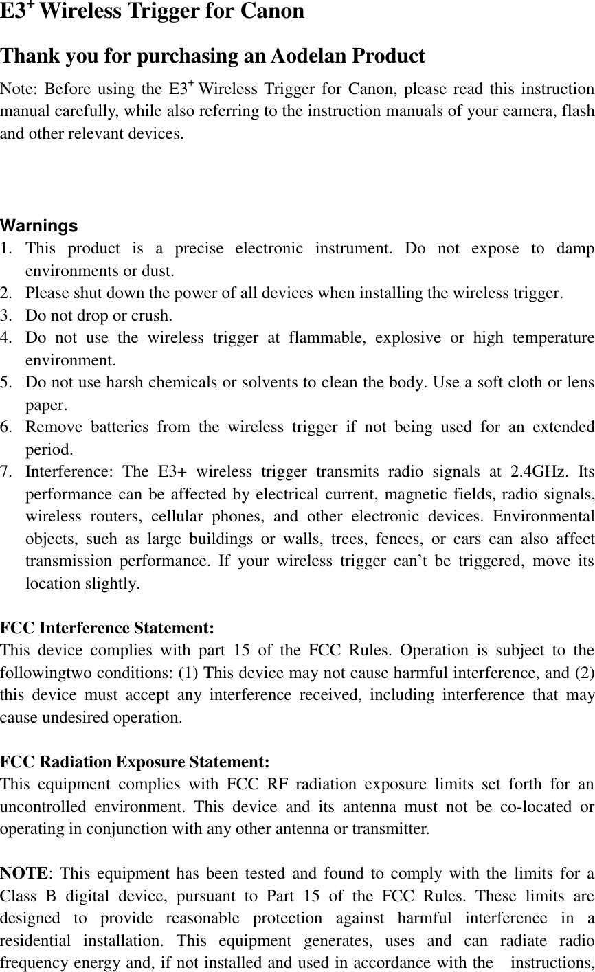
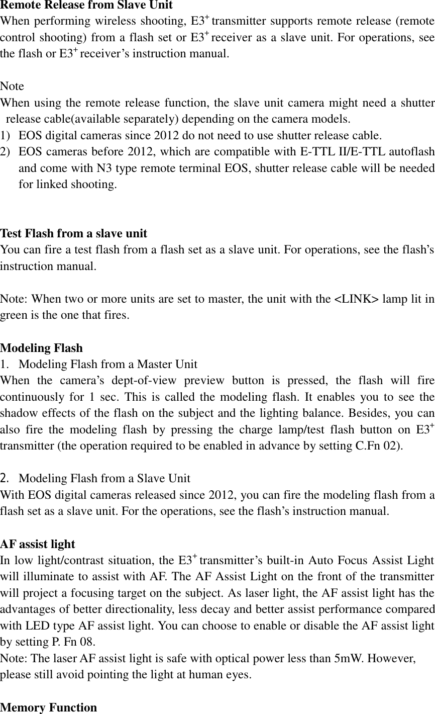
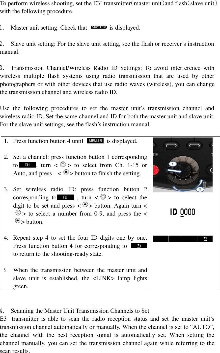
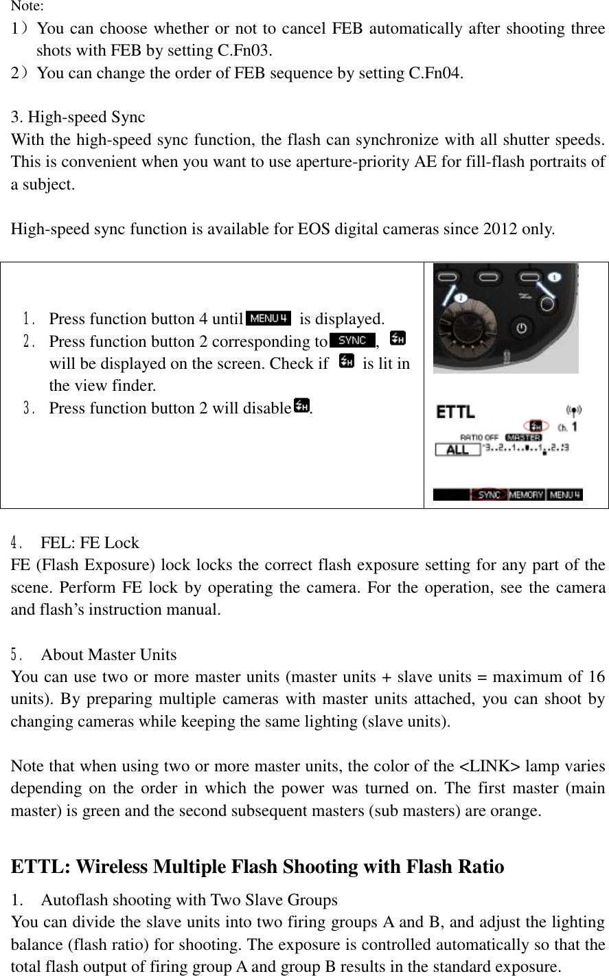
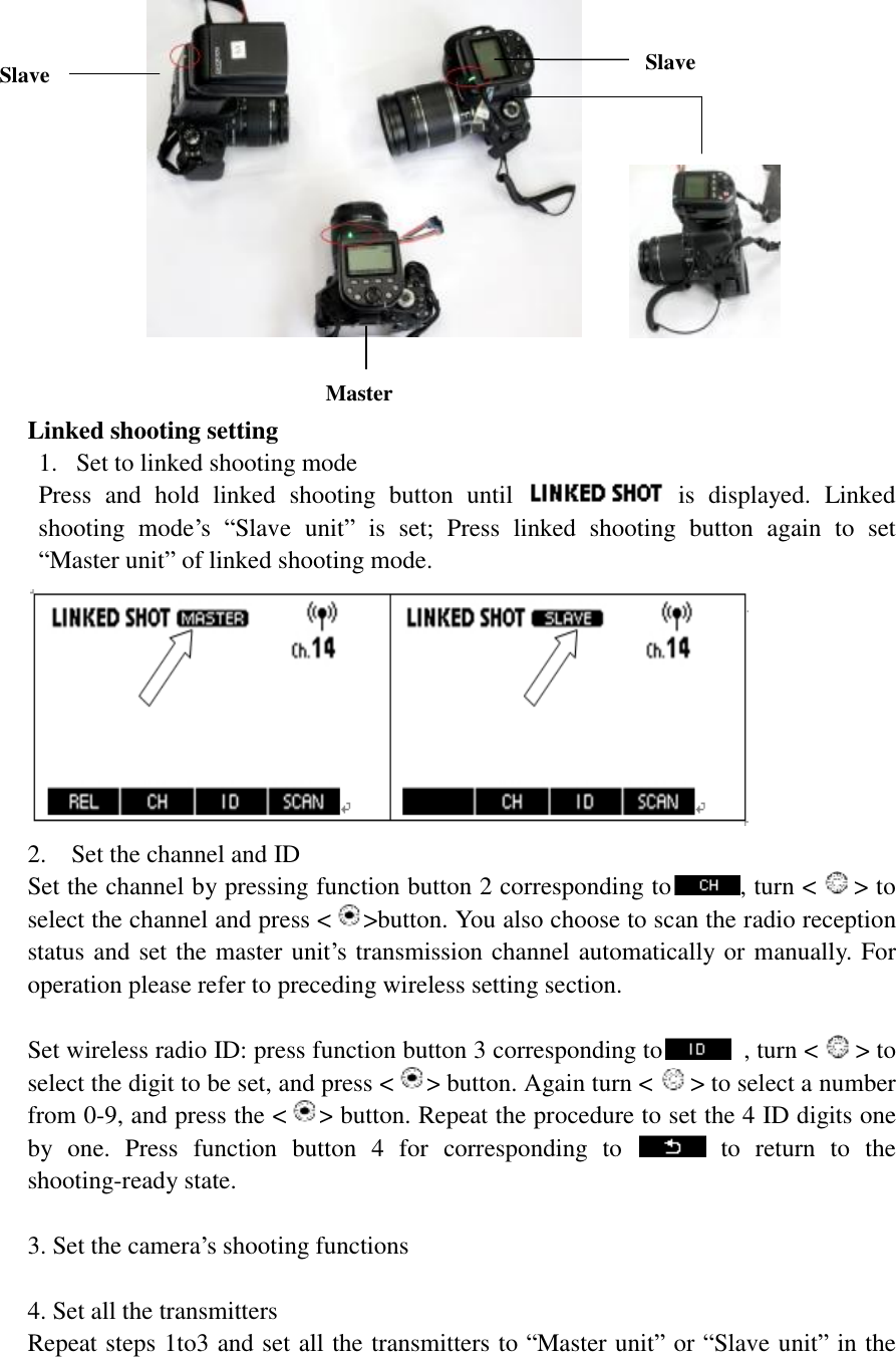
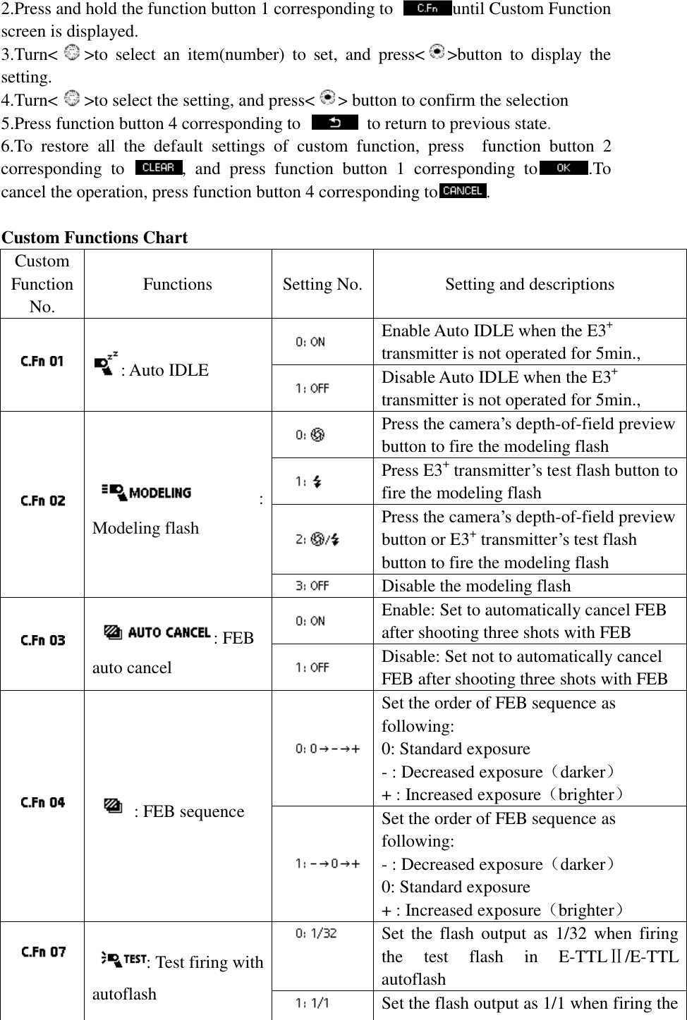
![1.Select [External Speedlite control]or[Flash control]. 2.Select[Flash function settings]or[External flash func. setting], the screen changes to the(external)flash function settings screen 3.Select an item and set the function.(The setting screen varies depending on the camera) 2.Settings Available in [Flash function settings] Flash firing [Enable] Enable wireless flash shooting [Disable] Disable wireless flash shooting E-TTLⅡflash metering [Evaluative] For normal exposures [Average] Flash exposure will be averaged for the entire scene metered by the camera. Flash exposure compensation may be necessary depending on the scene. This setting is for advanced users. Flash synchronization speed in AV mode You can set the flash sync speed when performing wireless flash shooting in aperture-priority AE(Av) mode Flash mode E-TTLⅡ/Manual flash/ MULTI flash /Individual group control Shutter synchronization 1st curtain / High-speed synchronization Flash exposure compensation Users can set the exposure compensation for flash up to ±3 stops in 1/3-stop increments. FEB Users can take three shots while automatically changing the flash output, with settable range up to ±3 stops in 1/3-stop increments. Wireless Radio transmission wireless flash](https://usermanual.wiki/Aodelan-Technology/TGTE3T/User-Guide-2608848-Page-25.png)
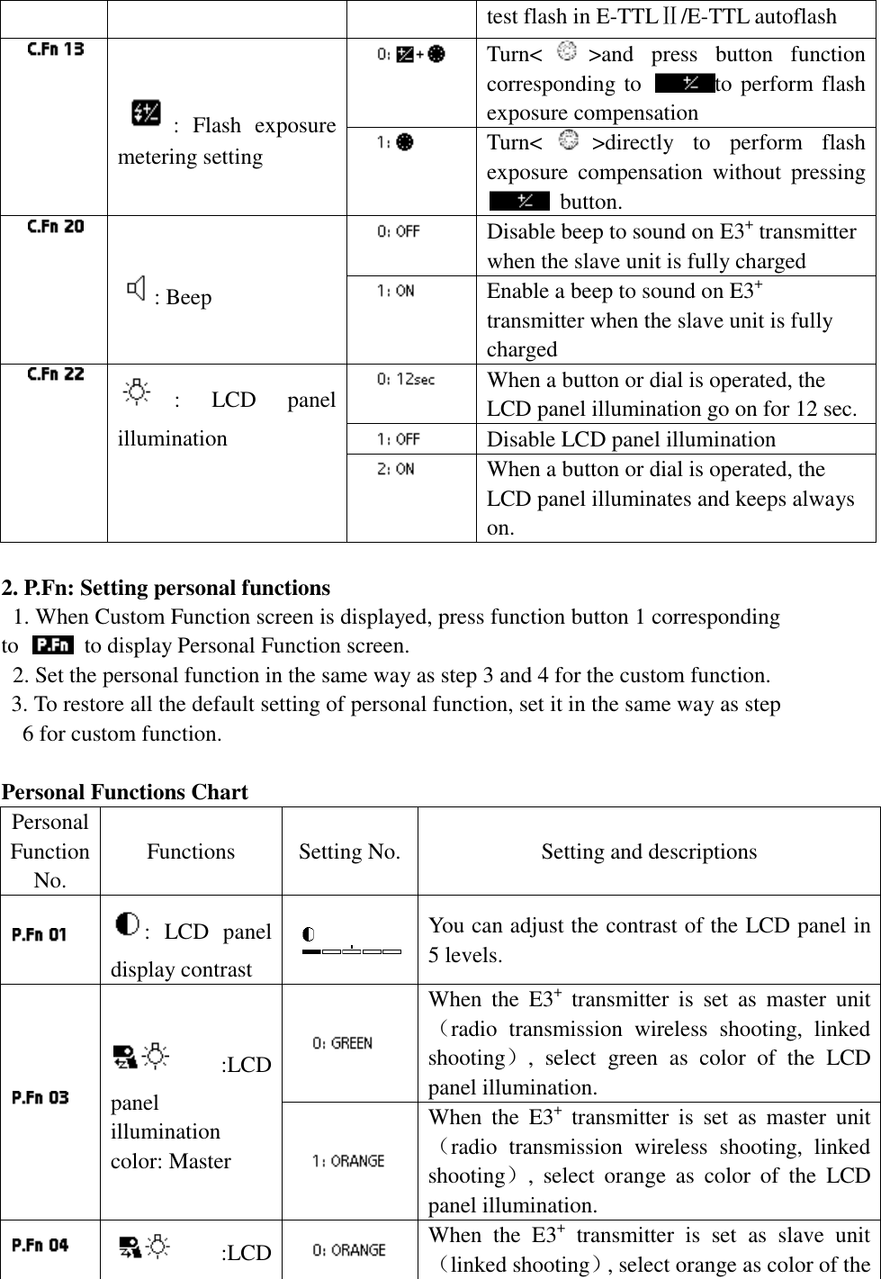
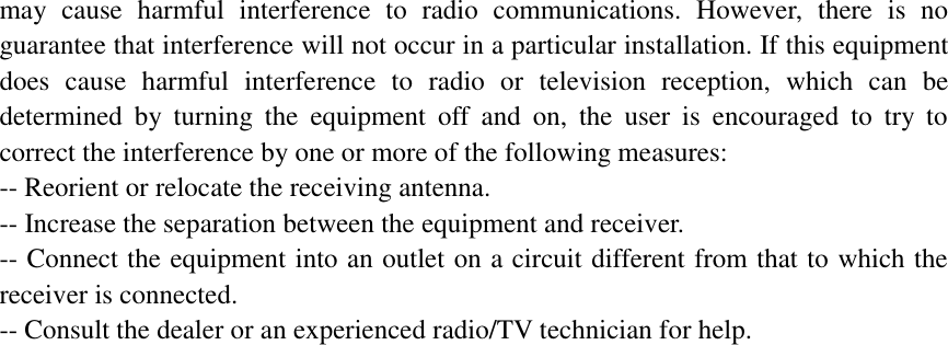
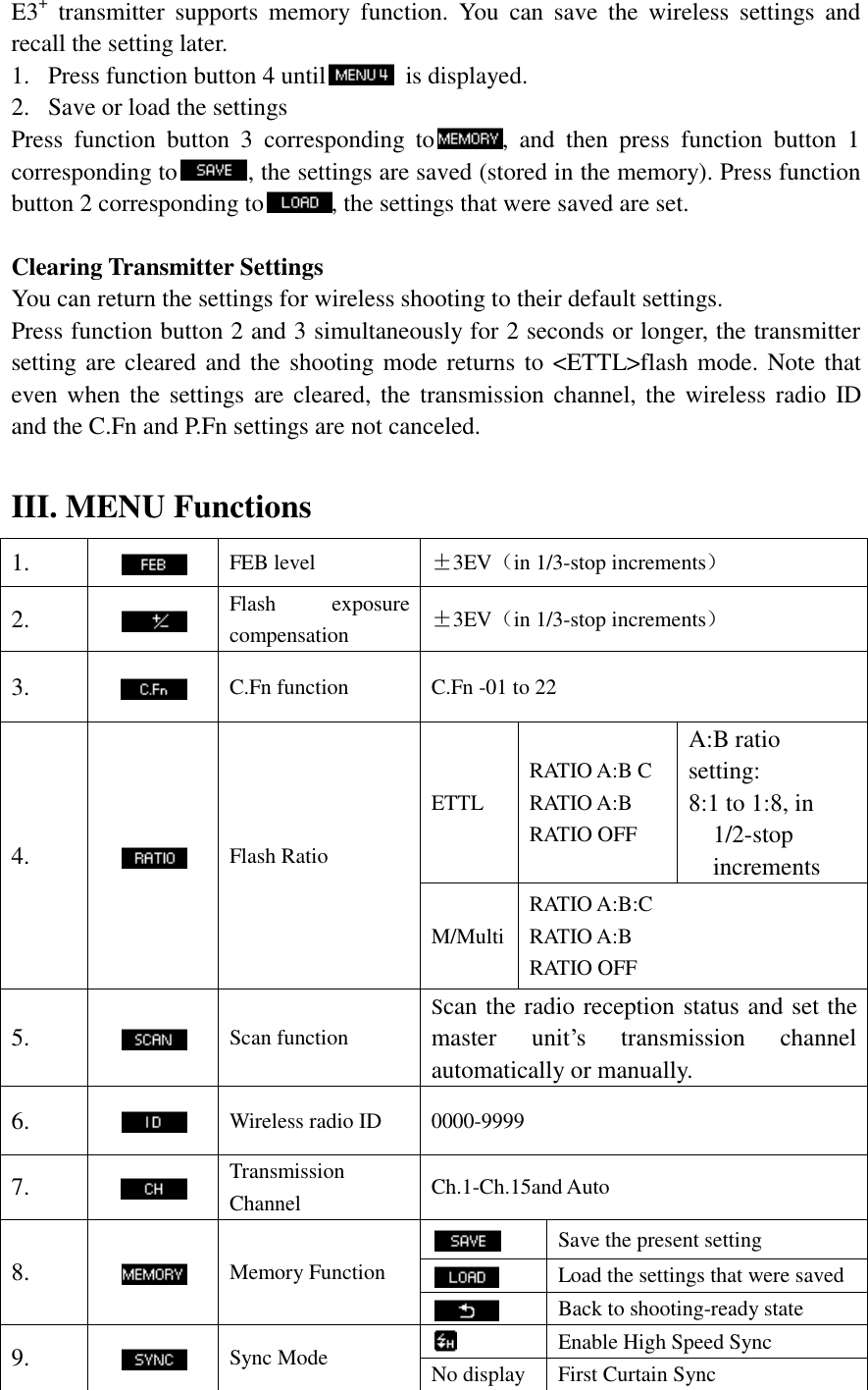
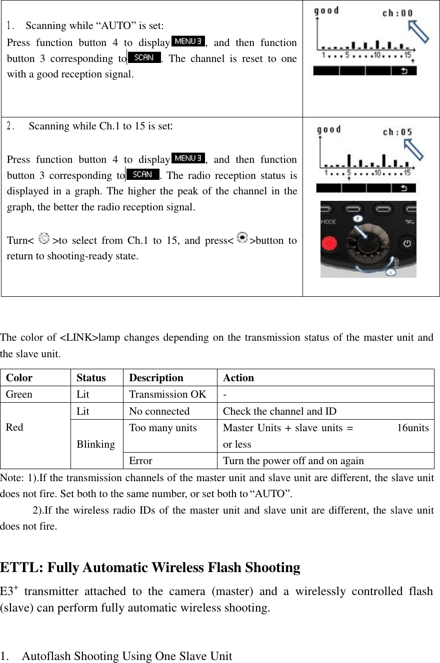
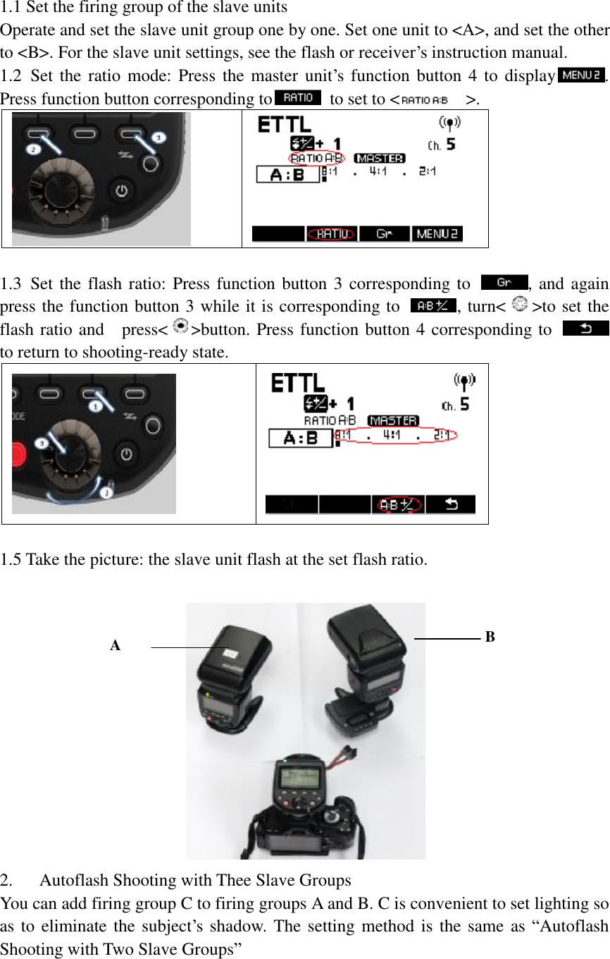
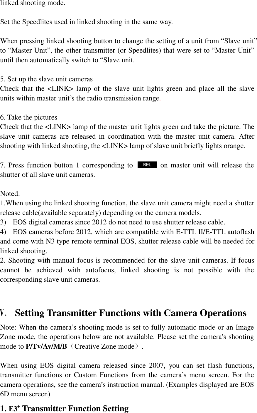
![flash functions(setting) shooting is set automatically.(*For EOS digital camera released since 2012). Clear Speedlite function settings You can restore E3+ transmitter to their default settings 3. Transmitter Custom Function Settings The displayed contents vary depending on the camera. If C.Fn-20 and 22 are not displayed, set them by operating the transmitter. 1. Select[Flash C.Fn settings]or[External flash C.Fn setting] 2. Select the Custom Function number and set function 3. To clear all the Custom Function settings, select [Clear all Speedlite C.Fn’s] or [Clear ext. flash C.Fn set] in step 1. Note: [Auto power off] under [Flash C.Fn settings] is corresponding to E3+transmitter’s C.Fn 01: Auto IDLE. You can enable or disable Auto IDLE for E3+transmitter by operating the Camera menu option. VI. Customizing the Transmitter E3+ Transmitter supports Custom function(C.Fn)and Personal Function(P.Fn)setting. You can customize the transmitter features to suit your shooting preferences with custom functions and personal functions. Note that the personal functions are customizable functions unique to the E3+ transmitter. Note: When the camera’s shooting mode is set to fully automatic mode or an Image Zone mode, the operations below are not available. Please set the camera’s shooting mode to P/Tv/Av/M/B(Creative Zone mode. 1. C.Fn: Setting custom functions 1.Press function button 4 until is displayed on the screen.](https://usermanual.wiki/Aodelan-Technology/TGTE3T/User-Guide-2608848-Page-26.png)