Apc Sgi 15000 Raid Users Manual Is15k_UG
007-5510-002 007-5510-002
15000 RAID to the manual d2be9961-40eb-490a-a525-f230fbefa6db
2015-02-03
: Apc Apc-Sgi-15000-Raid-Users-Manual-471105 apc-sgi-15000-raid-users-manual-471105 apc pdf
Open the PDF directly: View PDF ![]() .
.
Page Count: 152 [warning: Documents this large are best viewed by clicking the View PDF Link!]
- SGI® InfiniteStorage 15000 RAID User’s Guide
- Preface
- International Standards
- Potential for Radio Frequency Interference
- Note This equipment has been tested and found to comply with the limits for a class A digital device, pursuant to Part 15 of the...
- Important SGI InfiniteStorage 15000 drive enclosures must be always installed in SGI InfiniteStorage 15000 racks. SGI does not a...
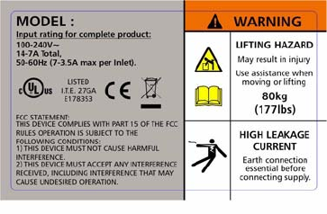
- Warning The SGI InfiniteStorage 15000 MUST be grounded before applying power.
- Warning To ensure protection against electric shock caused by HIGH LEAKAGE CURRENT (TOUCH CURRENT), the SGI InfiniteStorage 15000 must be connected to at least two separate and independent sources. This is to ensure a reliable earth connection.
- Warning To ensure your system has warning of a power failure please disconnect the power from the power supply, by either the switch (where present) or by physically removing the power source, prior to removing the PCM from the enclosure/shelf.
- Warning Do not remove covers from the PCM. Danger of electric shock inside. Return the PCM to your supplier for repair.
- Warning Operation of the Enclosure with ANY modules missing will disrupt the airflow and the drives will not receive sufficient cooling. It is ESSENTIAL that all apertures are filled before operating the unit.
- Important Observe all applicable safety precautions, e.g. weight restrictions, handling batteries and lasers etc., detailed in the preceding paragraphs when dismantling and disposing of this equipment
- Important SGI InfiniteStorage 15000 drive enclosures should only be installed in SGI InfiniteStorage 15000 racks. Mounting and installing these drive enclosures in any other rack is not authorized or supported by SGI.
- Warning It is recommended that you do not slide more than one enclosure out of the rack at a time, to avoid danger of the rack tipping over.
- 1.1 Controller Features
- 1.2 The Controller Hardware
- Figure 1-1 SGI InfiniteStorage 15000 IB - Front and Rear Views
- 1.2.1 Power Supply and Fan Modules
- 1.2.2 I/O Connectors and Status LED Indicators
- 1.2.3 Uninterruptible Power Supply (UPS)
- Chapter 2
- Controller Installation
- 1. Unpack the controller system.
- 2. If it is necessary to install the controller in the 19-inch cabinet(s), contact your service provider.
- 3. Set up and connect the drive enclosures to the controller.
- 4. Connect the controller to your Infiniband (IB) or Fibre Channel (FC) switch and host computer(s).
- 5. Connect your RS-232 terminal to the controller.
- 6. Power up the system.
- 7. Configure the storage array (create and format LUNs - Logical Units) via RS-232 interface, Telnet, or GUI.
- 8. Define and provide access rights for the clients in your SAN environment. Shared LUNs need to be managed by SAN management software. Individual dedicated LUNs appear to the client as local storage and do not require management software.
- 9. Initialize the system LUNs for use with your server/client systems. Partition disk space and create file systems as needed.
- 2.1 Setting Up the Controller
- 2.2 Unpacking the System
- 2.2.1 Rack-Mounting the Controller Chassis
- 2.2.2 Connecting the Controller in Dual Mode
- 2.2.3 Connecting the Controller
- 2.2.4 Selecting SAS- ID for Your Drives
- 2.2.5 Laying Out your Storage Drives
- 2.2.6 Connecting the RS-232 Terminal
- 2.2.7 Powering On the Controller
- 1. Verify that the power switches on the two (2) power supply module at the back of each controller are off.
- 2. Connect the two AC connectors, using the power cords provided at the back to the AC power source for each controller unit. For maximum redundancy, connect the two power connectors to two different AC power circuits for each unit.
- 3. Check that all your drive enclosures are powered up.
- 4. Check that the drives are spun up and ready.
- 5. Turn on the power supplies on the controller unit(s). The controller will undergo a series of system diagnostics and the bootup sequence is displayed on your terminal.
- 6. Wait until the bootup sequence is complete and the controller system prompt is displayed.
- 2.3 Configuring the Controller
- 2.3.1 Planning Your Setup and Configuration
- 2.3.2 Configuration Interface
- 2.3.3 Login as Administrator
- 2.3.4 Setting System Time & Date
- 2.3.5 Setting Tier Mapping Mode
- 2.3.6 Checking Tier Status and Configuration
- Figure 2-5 Tier Status Screen
- 1. If a drive is not displayed at all (that is, it is “missing”), check to ensure that the drive is properly seated and in good condition. To search for the drive, enter:
- 2. If the same channel is missing on all tiers, check the cable connections for that channel.
- 3. If “automatic disk rebuilding” is not enabled, enable it by entering:
- 4. To display the detailed disk configuration information for all of the tiers (Figure 2-6) enter:
- Figure 2-6 Current Tier Configuration
- 2.3.6.1 Heading Definitions
- Figure 2-5 Tier Status Screen
- 2.3.7 Cache Coherency and Labeling in Dual Mode
- 2.3.8 Configuring the Storage Arrays
- 1. To display the current cache settings, type: cache<Enter>
- 2. Select a cache segment size for your array. For example, to set the segment size to 128 KBytes, type:
- 3. Type: lun<Enter>.
- 4. To create a new LUN, type: lun add=x<Enter>
- 5. You will be prompted to enter the parameter values for the LUN. In this example:
- 6. When you are asked to format the LUN, type: y<Enter>
- Figure 2-9 Logical Unit Status - Formatting
- Figure 2-10 LUN Status - Ready
- 2.3.9 Setting Security Levels
- 2.3.9.1 User Authentication (Recommended for SAN Environment)
- 1. Enter: zoning<Enter>
- 2. Check to ensure that the LUN Zoning chart is empty (Figure 2-11).
- Figure 2-11 LUN Zoning Screen
- To add a user:
- 1. Type: user audit=on<Enter> The controller reports which users are connected.
- 2. Type: user add<Enter>.
- 3. Specify a new Host User’s world wide name, enter s.
- 4. Specify a 64-bit world wide name or GUID, taken from the list of available anonymous users.
- 5. Enter an alias name for the user. The name may contain up to 12 characters. Type in a name and press <Enter>.
- 6. Host users can have their port access zoned. Enter y to specify host port zoning.
- 7. For Unit 1, enter each active port on a new line and then exit. For this example, type: 1<Enter> 4<Enter> e<Enter>
- 8. For Unit 2, enter each active port on a new line and then exit. For this example, type: 1<Enter> 4<Enter> e<Enter>
- 9. Enter y to specify the unique LUN mapping (Table 2-2).
- 10. Enter a new unique LUN mapping for this user. Options are shown in Table 2-2 on page 26.
- To add a user:
- Table 2-2 LUN Mapping Options.
- Figure 2-12 Security Settings Screen
- 2.3.9.2 Host Port Zoning (Anonymous Access)
- 1. To edit the default zoning on a host port, type: zoning edit<Enter>. The current settings are displayed.
- 2. Select a host port (1..4): 1<Enter>
- 3. Specify the internal LUN (0..1023) to be mapped to the external LUN. The new settings will display .
- 4. Repeat steps 1-3 to configure other host ports.
- Chapter 3
- Controller Management
- 2.3.9.1 User Authentication (Recommended for SAN Environment)
- 3.1 Managing the Controller
- Locally - Serial Interface
- Remotely - Telnet
- Host WWN
- Disk and Channel Information
- Figure 3-9 Disk Channel Screen
- Figure 3-10 Disk Status Screen
- Figure 3-11 Disk Defect List Screen
- Table 3-2 PHY Link Error Status Block Information
- Figure 3-12 Disk PLS Tier 1 Status Screen
- 3.2.2.1 Tier View
- 3.2.2.2 Tier Configuration
- 3.2.2.3 LUN View
- 3.2.2.4 LUN Configuration
- 3.2.2.5 LUN Reservations
- 3.2.2.6 Adding/Removing Storage Assets
- 3.2.2.7 Status of Drive Enclosures
- 3.2.2.8 Display SES Devices Information
- 3.2.2.9 Visual Indication of Drive
- 3.2.2.10 Visual Indication of Tier
- 3.2.2.11 Visual Indication of Channel
- 3.2.3 Tier Mapping for Enclosures
- 3.2.4 System Network Configuration
- 3.2.5 Restarting the Controller
- 3.2.6 Setting the System’s Date and Time
- 3.2.7 Saving the Controller’s Configuration
- 3.2.8 Restoring the System’s Default Configuration
- 3.2.9 LUN Management
- SCSI Reservations
- Non-Cache Coherent
- Display Current Cache Settings
- Disk Configuration Settings
- Figure 3-30 Disk Configuration Setting Screen
- 3.3.2 Audio/Visual Settings of the System
- 3.3.3 Locking LUN in Cache
- 3.3.3.1 Locking / Unlocking a LUN
- 3.3.3.2 System Performance Statistics
- Figure 3-33 System Performance Statistics Screen
- Figure 3-34 Command Delay Statistics Screen
- Figure 3-35 Host Delay Statistics Screen
- Figure 3-36 Tier Delay Statistics Screen
- Figure 3-37 Host Command Offsets Screen
- Figure 3-38 Dual Message Statistics Screen
- Figure 3-39 Command Length Statistics Screen
- Figure 3-40 Host Command Offsets Screen
- 3.3.4 Resources Allocation
- Background Format/Rebuild Operations
- Figure 3-41 Displaying the Current Rebuild Parameters
- 3.3.4.1 Background LUN Verify Operations
- 3.3.4.2 Background TIER Verify Operations
- 1. At the prompt, type TIER VERIFY=ON <Enter>.
- 2. The system will ask which tier you wish to verify. Enter the tier number or type a for “All.”
- 3. The system will ask if you want run the Tier Verify operation continuously or not. Type y to run continuously or N to run just once. The default is N.
- Figure 3-42 Tier Verify ON Screen
- Figure 3-43 Tier Verify OFF Screen
- 3.3.4.3 Rebuild Journaling
- 3.3.4.4 SES Device Monitoring Rate
- 3.3.4.5 Host Command Timeout
- 3.4 Security Administration
- 3.5 Firmware Update Management
- 3.5.1 Displaying Current Firmware Version
- 3.5.2 Firmware Update Procedure
- 1. Collect and save the output of the following commands before you update the firmware: VERSION AV CACHE DISK DISK LIST DUAL HOST HOST STATUS LOG LUN LUN CONFIG NETWORK STATS STATS DELAY STATS TIER DELAY TIER TIER CONFIG
- 2. Copy the new firmware file to your TFTP server.
- 3. Connect to the controller via Telnet or serial (CLI port).
- 4. Enter TFTP
- 5. You will be asked to confirm action (Figure 3-53). Enter y to continue.
- Figure 3-53 Downloading Controller Firmware
- 6. Enter the TFTP server’s IP address: TFTP <IP_address>
- 7. Enter the firmware path and filename: TFTP <filename>
- 8. For the couplet controller configuration, connect and log into the other controller. Repeat Steps 4- 7 above to update the firmware.
- 9. Enter RESTART to restart the unit(s).
- 10. (For dual mode only): After both controllers are back on-line, use the DUAL command to verify that both controller units are healthy. If either controller shows failed, login to the healthy controller and issue the DUAL HEAL command.
- 3.6 Remote Login Management
- 3.7 System Logs
- 3.7.1 Message Log
- 3.7.2 System and Drive Enclosure Faults
- Figure 3-59 Current System Faults
- To display the current SDRAM memory faults (ECC- error controller counters), use FAULTS MEMORY command. To clear the values in the memory faults (ECC) statistics, use FAULTS MEMCLEAR command.
- To display the current status of the host and disk SFPs, use the FAULTS SFP command.
- To display the number of LUN array parity errors detected by the system, use the FAULTS ARRAYPARITY command. The system saves th...
- FAULTS BUSPARITY displays the number of bus parity and data path errors detected by the system.
- FAULTS BUSPARITYCLEAR clears the count of errors.
- You may set a parameter (ECCSHUTDOWN) that allows the system to automatically shutdown if it encounters an unrecoverable error. ...
- The EXCEPTIONSHUTDOWN command parameter allows the system to automatically shutdown if it encounters a task exception.
- FAULTS EXCEPTIONSHUTDOWN=ON enables automatic shutdown for task exceptions. This is the default setting.
- The FAULTS EXCEPTIONSHUTDOWN=OFF disables automatic shutdown and allows the system to continue to run in spite of task exceptions.
- Figure 3-59 Current System Faults
- 3.7.3 Displaying System Uptime
- 3.7.4 Saving a Comment to the Log
- 3.8 Other Utilities
- 4.1 Remote Management of the Controller
- 4.1.1 Network Connection
- 4.1.2 Network Interface Set Up
- 1. Use the NETWORK command to display the current settings (Figure 4-2).
- 2. Change the controller’s IP address for your network environment: network IP=<new IP address>.
- 3. Change the netmask of the controller (if needed): network netmask=<new netmask>.
- 4. Enable the Telnet capability (if needed): network telnet=ON.
- 5. Decide whether the SNMP functionality should be enabled.
- Figure 4-2 Current Network Configuration Screen
- 6. If the SNMP function is enabled, enter the IP address of the computer to be used to monitor the SNMP traps: network trapip=<computer’s IP address>
- 7. Decide whether the Syslog capability should be enabled. To enable (ON) or disable (OFF) the Syslog, enter: network syslog=on|off
- 8. If the SYSLOG function is enabled, enter the destination IP address for the Syslog packets: network SYSLOGIP=<destination IP address>
- 9. The default destination port number for Syslog packets is 514. To change it, enter: network SYSLOGPORT=<port number>
- 10. Set up the routing table. This table describes how the controller communicates with the hosts on other networks. Use the ROUTE command to display the current settings (Figure 4-3).
- Figure 4-3 Current Controller Routing Table
- 4.1.3 Login Names and Passwords
- 4.1.4 SNMP Set Up on Host Computer
- 1. Ensure the host computer, which will receive the traps, has an SNMP browser (such as HP OpenView) properly installed and configured. Refer to your browser’s documentation for instructions on how to load the MIB files.
- 2. Set up the host computer to listen to Ports 161 and 162.
- 3. Load the following controller MIB. Note these MIB files:
- 4. Start a query. You should be able to see various controller information such as tempLevel, powerNumber, fanNumber, powerTable, tierNumber, and tierTable.
- 5. To verify that the SNMP function has been set up correctly:
- a) Unplug one of the power supplies.
- b) Check that a power failure message appears in your SNMP browser.
- 4.1.4.1 Controller Implementation of SNMP
- InfiniteStorage 15000 MIB (The InfiniteStorage 15000 MIB is read only.)
- 4.1.4.2 Traps
- 4.2 Troubleshooting the Controller
- 4.2.1 Component Failure Recovery
- 4.2.1.1 Power Supply Failure
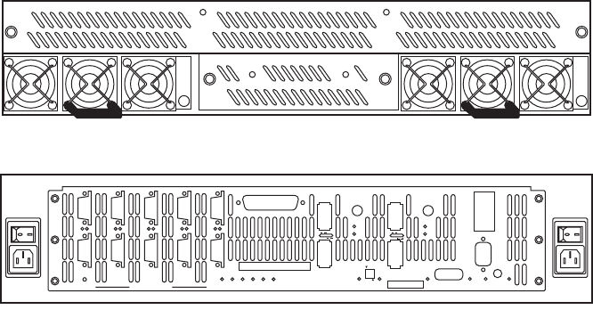
- Figure 4-4 Power Modules - Front View
- 1. Remove the cover panel (if the panel is installed).
- 2. Locate the failed power supply module (indicated by an off Status LED).
- 3. Turn off module’s power switch (found on back of unit).
- 4. Remove the module’s thumbscrews, then slide the module out of the bay.
- 5. Slide the module into the bay making sure it is fully inserted. Install the two thumbscrews to secure it.
- 6. Turn on the power switch. Check that the Status LED is green, indicating that the module is operating normally.
- 7. Replace the cover panel (if necessary).
- Figure 4-4 Power Modules - Front View
- 4.2.1.2 Fan Failure
- 4.2.1.1 Power Supply Failure
- 4.2.2 Recovering from Drive Failures
- 4.2.2.1 Single Drive Failures
- 4.2.2.2 Returning the System to a Fault-Tolerant State
- 4.2.2.3 Manually Replacing a Failed Disk with Spare Disk
- 4.2.2.4 Changing the Rate of Rebuild
- 4.2.2.5 Interrupting the Rebuild Operation
- 4.2.2.6 Multiple Drive and Channel Failures
- 1. Use the TIER command to check the current disk status and see if the drives failed are all on the same channel.
- 2. Use the DISK command to check the status of the channel.
- 1. Contact SGI technical support to determine the cause of error and what steps may need to be taken to recover form the error.
- 2. Isolate the cause of channel failure (for example, loose cable connections).
- 3. Rebuild all the drives on that channel individually by issuing the command:
- 4.2.3 Component Failure on Enclosures
- 4.2.1 Component Failure Recovery
- 5.1 The SGI InfiniteStorage 15000 Drive Enclosure
- 5.2 Enclosure Core Product
- 5.3 The Plug-in Modules
- 5.4 Indicators
- 5.5 Visible and Audible Alarms
- 5.6 Drive Enclosure Technical Specification
- 5.7 Environment
- 6.1 Introduction
- 6.2 Planning Your Installation
- Before you begin installation, you should become familiar with the configuration requirements of your drive enclosure system and the correct positions of each of the optional plug-in modules (Table 6-1).
- Table 6-1 Drive Enclosure Configuration
- Figure 6-1 DEM Pair Locations
- 6.2.1 Enclosure Bay Numbering Convention
- 6.3 Enclosure Installation Procedures
- Important SGI InfiniteStorage 15000 drive enclosures should only be installed in SGI InfiniteStorage 15000 racks. Mounting and installing these drive enclosures in any other rack is not authorized or supported by SGI.
- Warning The drive enclosure with all its component parts installed is too heavy for a single person to easily install into a Rack cabinet.
- Caution Ensure that you have fitted and checked a suitable anti-static wrist or ankle strap and observe all conventional ESD pre...
- Note Drive enclosures are supplied and delivered populated with Backplane, Baseplane, Front Panel, DEMs, and with PCMs installed. The Drive Carrier Modules are supplied as a separate package.
- 6.4 I/O Module Configurations
- 6.5 SAS DEM
- 6.6 SATA Interposer Features
- 6.7 Drive Enclosure Device Addressing
- 6.8 Grounding Checks
- 7.1 Before You Begin
- 7.2 Power On / Power Down
- Caution Do not operate the subsystem until the ambient temperature is within the specified operating range. If the drives have been recently installed, ensure they have had time to acclimatize before operating them.
- Important If AC power is lost for any reason, on restoration of power the enclosure will re-start automatically.
- 7.2.1 PCM LEDs
- 7.2.2 I/O Panel LEDs
- 8.1 Overview
- 8.2 Initial Start-up Problems
- 8.2.1 Faulty Cords
- 8.2.2 Alarm Sounds On Power Up
- 8.2.3 Green “Signal Good” LED on I/O Module Not Lit
- 8.2.4 Computer Doesn’t Recognize the Drive Enclosure Subsystem
- 1 Check that the SAS interface cables from the drive enclosure to the host computer, or I/O controller, are fitted correctly.
- 2 Check that all drive carrier modules have been correctly installed.
- 3 Check that there is a valid SAS signal present at the I/O connector. If there is no signal present, ensure the cable has been properly inserted.
- 4 Check the I/O module setup as follows:
- 8.3 LEDs
- 8.4 Audible Alarm
- 8.5 Troubleshooting
- 8.5.1 Thermal Control
- 1 Check the installation for any airflow restrictions at either the front or rear of the enclosure. A minimum gap of 25mm at the front and 50mm at the rear is recommended.
- 2 Check for restrictions due to dust build-up; clean as appropriate.
- 3 Check for excessive re-circulation of heated air from rear to the front. Use in a fully enclosed rack installation is not recommended.
- 4 Check that all Blank modules are in place.
- 5 Reduce the ambient temperature.
- 8.5.2 Thermal Alarm
- 1 Check local ambient environment temperature is below the upper 40˚C specification.
- 2 Check the installation for any airflow restrictions at either the front or rear of the enclosure. A minimum gap of 25mm at the front and 50mm at the rear is recommended.
- 3 Check for restrictions due to dust build-up. Clean as appropriate.
- 4 Check for excessive re-circulation of heated air from rear to the front. Use in a fully enclosed rack installation is not recommended.
- 5 If possible, shutdown the enclosure and investigate the problem before continuing.
- 8.5.3 Thermal Shutdown
- 8.5.1 Thermal Control
- 8.6 Dealing with Hardware Faults
- 8.7 Continuous Operation During Replacement
- 8.8 Replacing a Module
- Warning Whenever replacing a module NEVER leave an EMPTY bay in the rear of the enclosure, obtain a replacement before removing the problem part.
- Warning Observe all conventional ESD precautions when handling drive enclosure modules and components. Avoid contact with Backplane components and module connectors, etc.
- 8.8.1 Power Cooling Modules
- Warning Do not remove covers from the Power Cooling module (PCM). There is a danger of electric shock. Return the PCM to your supplier for repair.
- Warning To ensure your system has warning of a power failure please disconnect the power from the power supply, by either the sw...
- Warning Do not remove the faulty PCM/Cooling module unless you have a replacement unit of the correct type ready for insertion.
- 1 Make sure you identify the faulty PCM correctly from the two modules installed.
- 2 Lift latch which secures the power supply cord.
- 3 Switch off and disconnect the power supply cord.
- 4 Lift the PCM handle to the open position to cam the PCM out of the enclosure.
- 5 Grip the handle and withdraw the PCM.
- 1 Make sure you identify the faulty PCM correctly from the two modules installed.
- 2 Lift latch which secures the power supply cord.
- 3 Switch off and disconnect the power supply cord.
- 4 Remove the two thumbscrews on the right and left sides of the unit.
- 5 Firmly grip the handle on the bottom of the unit and withdraw the PCM.
- 6 Check for damage, especially to the rear connector on the PCM.
- 7 With the PCM handle in the open position, slide the module into the enclosure.
- 8 Cam the module home by manually closing the PCM handle. A click should be heard as the handle latches engage.
- 9 Connect the power supply cord to the power source, secure the latch over the cord, and switch the power supply ON.
- 1 Check for damage, especially to the rear connector on the PCM.
- 2 Slide the module into the enclosure and push unit you hear a click as the latch is engaged.
- 3 Secure the two thumbscrews on the left and right sides of the unit.
- 4 Connect the power supply cord to the power source; secure latch, and switch the power supply ON.
- 8.8.2 I/O Module
- Warning Do not remove this module unless a replacement can be immediately added. The system must not be run without all units in place.
- 1 Release the two latches on the bottom of the unit by simply pulling each latch out and away from unit.
- 2 Pull the latches forward to cam the module out of the enclosure.
- 3 Grip the unit securely and withdraw the module.
- 4 With the latches in the open position, slide the EBOD module into the enclosure until the latch engages automatically.
- 5 Cam the module home by manually closing the latches. A click should be heard as the latch engages.
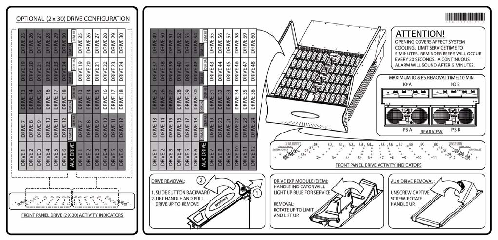
- 8.8.3 Replacing the Drive Carrier Module
- Warning Observe all conventional ESD precautions when handling drive enclosure modules and components. Avoid contact with backplane components and module connectors, etc.
- 1 Release the carrier handle by sliding the latch backwards.
- 2 Insert the carrier into the enclosure.
- 3 Slide the drive carrier, gently, all the way into the enclosure.
- 4 Cam the drive carrier home. The camming foot on the base of the carrier will engage into a slot in the enclosure.
- 5 When the carrier is fully home, close the handle. You should hear a click as the latch engages and holds the handle closed.
- 6 Close the enclosure.
- 8.9 Replacing the DEM
- A
- B
- C

SGI® InfiniteStorage 15000 RAID
User’s Guide
007-5510-002
COPYRIGHT
© 2008 SGI. All rights reserved; provided portions may be copyright in third parties, as indicated elsewhere herein.
No permission is granted to copy, distribute, or create derivative works from the contents of this electronic
documentation in any manner, in whole or in part, without the prior written permission of SGI.
LIMITED RIGHTS LEGEND
The software described in this document is “commercial computer software” provided with restricted rights (except
as to included open/free source) as specified in the FAR 52.227-19 and/or the DFAR 227.7202, or successive
sections. Use beyond license provisions is a violation of worldwide intellectual property laws, treaties and
conventions. This document is provided with limited rights as defined in 52.227-14.
The electronic (software) version of this document was developed at private expense; if acquired under an agreement
with the USA government or any contractor thereto, it is acquired as “commercial computer software” subject to the
provisions of its applicable license agreement, as specified in (a) 48 CFR 12.212 of the FAR; or, if acquired for
Department of Defense units, (b) 48 CFR 227-7202 of the DoD FAR Supplement; or sections succeeding thereto.
Contractor/manufacturer is SGI, 1140 E. Arques Avenue, Sunnyvale, CA 94085.
TRADEMARKS AND ATTRIBUTIONS
SGI and the SGI logoare registered trademarks of SGI in the United States and/or other countries worldwide.
Windows is a registered trademark of Microsoft Corporation in the United States and/or other countries.
All other trademarks mentioned herein are the property of their respective owners.
Contents
007-5510-002 i
1 Introduction ..................................................................................................................................... 1
1.1 Controller Features ...................................................................................................................... 1
1.2 The Controller Hardware ............................................................................................................. 2
1.2.1 Power Supply and Fan Modules ........................................................................................ 4
1.2.2 I/O Connectors and Status LED Indicators ........................................................................ 5
1.2.3 Uninterruptible Power Supply (UPS) .................................................................................. 9
2 Controller Installation ................................................................................................................... 11
2.1 Setting Up the Controller ........................................................................................................... 11
2.2 Unpacking the System .............................................................................................................. 12
2.2.1 Rack-Mounting the Controller Chassis ............................................................................. 12
2.2.2 Connecting the Controller in Dual Mode .......................................................................... 12
2.2.3 Connecting the Controller ................................................................................................. 13
2.2.4 Selecting SAS- ID for Your Drives .................................................................................... 13
2.2.5 Laying Out your Storage Drives ....................................................................................... 13
2.2.6 Connecting the RS-232 Terminal ..................................................................................... 14
2.2.7 Powering On the Controller .............................................................................................. 15
2.3 Configuring the Controller ......................................................................................................... 16
2.3.1 Planning Your Setup and Configuration ........................................................................... 16
2.3.2 Configuration Interface ..................................................................................................... 17
2.3.3 Login as Administrator ...................................................................................................... 17
2.3.4 Setting System Time & Date ............................................................................................ 17
2.3.5 Setting Tier Mapping Mode .............................................................................................. 18
2.3.6 Checking Tier Status and Configuration ........................................................................... 19
2.3.7 Cache Coherency and Labeling in Dual Mode ................................................................. 20
2.3.8 Configuring the Storage Arrays ........................................................................................ 21
2.3.9 Setting Security Levels ..................................................................................................... 24
3 Controller Management ................................................................................................................ 29
3.1 Managing the Controller ............................................................................................................ 29
3.1.1 Management Interface ..................................................................................................... 29
3.1.2 Available Commands ....................................................................................................... 30
3.1.3 Administrator and User Logins ......................................................................................... 30
3.2 Configuration Management ....................................................................................................... 32
3.2.1 Configure and Monitor Status of Host Ports ..................................................................... 32
3.2.2 Configure and Monitor Status of Storage Assets ............................................................. 34
3.2.3 Tier Mapping for Enclosures ............................................................................................ 42
3.2.4 System Network Configuration ......................................................................................... 43
3.2.5 Restarting the Controller ..................................................................................................45
3.2.6 Setting the System’s Date and Time ................................................................................ 46
3.2.7 Saving the Controller’s Configuration ............................................................................... 47
3.2.8 Restoring the System’s Default Configuration .................................................................. 47
3.2.9 LUN Management ............................................................................................................ 48
3.2.10 Automatic Drive Rebuild ...................................................................................................50
3.2.11 SMART Command ........................................................................................................... 51
3.2.12 Couplet Controller Configuration (Cache/Non-Cache Coherent) ..................................... 53
3.3 Performance Management ........................................................................................................ 55
3.3.1 Optimizing I/O Request Patterns ...................................................................................... 55
3.3.2 Audio/Visual Settings of the System ................................................................................ 58
3.3.3 Locking LUN in Cache ...................................................................................................... 59
3.3.4 Resources Allocation ........................................................................................................ 66
ii 007-5510-002
3.4 Security Administration ............................................................................................................. 72
3.4.1 Monitoring User Logins .................................................................................................... 73
3.4.2 Zoning (Anonymous Access) ........................................................................................... 73
3.4.3 User Authentication .......................................................................................................... 74
3.5 Firmware Update Management ................................................................................................. 75
3.5.1 Displaying Current Firmware Version .............................................................................. 75
3.5.2 Firmware Update Procedure ............................................................................................ 75
3.6 Remote Login Management ......................................................................................................76
3.6.1 When a Telnet Session is Active ..................................................................................... 77
3.7 System Logs ............................................................................................................................. 79
3.7.1 Message Log ................................................................................................................... 79
3.7.2 System and Drive Enclosure Faults ................................................................................. 79
3.7.3 Displaying System Uptime ............................................................................................... 80
3.7.4 Saving a Comment to the Log ......................................................................................... 80
3.8 Other Utilities ............................................................................................................................. 81
3.8.1 APC UPS SNMP Trap Monitor ........................................................................................ 81
3.8.2 API Server Connections ................................................................................................... 81
3.8.3 Changing Baud Rate for the CLI Interface ...................................................................... 81
3.8.4 CLI/Telnet Session Control Settings ................................................................................ 82
3.8.5 Disk Diagnostics .............................................................................................................. 82
3.8.6 Disk Reassignment and Miscellaneous Disk Commands ................................................ 83
3.8.7 SPARE Commands ......................................................................................................... 83
4 Controller Remote Management and Troubleshooting ............................................................. 85
4.1 Remote Management of the Controller ..................................................................................... 85
4.1.1 Network Connection .........................................................................................................85
4.1.2 Network Interface Set Up ................................................................................................. 85
4.1.3 Login Names and Passwords .......................................................................................... 87
4.1.4 SNMP Set Up on Host Computer .................................................................................... 88
4.2 Troubleshooting the Controller .................................................................................................. 89
4.2.1 Component Failure Recovery .......................................................................................... 89
4.2.2 Recovering from Drive Failures ....................................................................................... 90
4.2.3 Component Failure on Enclosures ................................................................................... 94
5 Drive Enclosure System ............................................................................................................... 95
5.1 The SGI InfiniteStorage 15000 Drive Enclosure ....................................................................... 95
5.2 Enclosure Core Product ............................................................................................................ 96
5.2.1 Enclosure Chassis ........................................................................................................... 97
5.3 The Plug-in Modules ................................................................................................................. 97
5.3.1 Power Cooling Module (PCM) ......................................................................................... 97
5.3.2 Input/Output (I/O) Module ................................................................................................ 98
5.3.3 Drive Carrier Module and Status Indicator ..................................................................... 100
5.3.4 DEM Card ...................................................................................................................... 100
5.4 Indicators ................................................................................................................................. 101
5.4.1 Front Panel Drive Activity Indicators .............................................................................. 101
5.4.2 Internal Indicators .......................................................................................................... 104
5.4.3 Rear of Enclosure Activity Indicators ............................................................................. 104
5.5 Visible and Audible Alarms ..................................................................................................... 105
5.6 Drive Enclosure Technical Specification ................................................................................. 105
5.6.1 Dimensions .................................................................................................................... 105
5.6.2 Weight ............................................................................................................................ 106
Contents
007-5510-002 iii
5.6.3 AC INPUT PCM .............................................................................................................. 106
5.6.4 DC INPUT PCM ............................................................................................................. 106
5.6.5 DC OUTPUT PCM ......................................................................................................... 107
5.6.6 PCM Safety and EMC Compliance ................................................................................ 107
5.6.7 Power Cord .................................................................................................................... 107
5.7 Environment ............................................................................................................................ 107
6 Drive Enclosure Installation ....................................................................................................... 109
6.1 Introduction .............................................................................................................................. 109
6.2 Planning Your Installation ........................................................................................................ 109
6.2.1 Enclosure Bay Numbering Convention .......................................................................... 110
6.3 Enclosure Installation Procedures ........................................................................................... 112
6.4 I/O Module Configurations ...................................................................................................... 112
6.4.1 Controller Options .......................................................................................................... 112
6.5 SAS DEM ................................................................................................................................ 113
6.6 SATA Interposer Features ....................................................................................................... 113
6.7 Drive Enclosure Device Addressing ........................................................................................ 113
6.8 Grounding Checks ................................................................................................................... 113
7 Drive Enclosure Operation ......................................................................................................... 115
7.1 Before You Begin .................................................................................................................... 115
7.2 Power On / Power Down ......................................................................................................... 115
7.2.1 PCM LEDs ...................................................................................................................... 115
7.2.2 I/O Panel LEDs ............................................................................................................... 116
8 Drive Enclosure Troubleshooting ............................................................................................. 117
8.1 Overview ................................................................................................................................. 117
8.2 Initial Start-up Problems .......................................................................................................... 117
8.2.1 Faulty Cords ................................................................................................................... 117
8.2.2 Alarm Sounds On Power Up .......................................................................................... 117
8.2.3 Green “Signal Good” LED on I/O Module Not Lit ........................................................... 117
8.2.4 Computer Doesn’t Recognize the Drive Enclosure Subsystem .................................... 117
8.3 LEDs ........................................................................................................................................ 118
8.3.1 HDD (Hard Disk Drive) ................................................................................................... 118
8.3.2 PCM (Power Cooling Module) ........................................................................................ 118
8.3.3 DEM (Drive Expander Module) ...................................................................................... 118
8.3.4 I/O Module ...................................................................................................................... 119
8.3.5 Front Panel Drive Activity Indicators .............................................................................. 120
8.4 Audible Alarm .......................................................................................................................... 121
8.4.1 Top Cover Open ............................................................................................................. 121
8.4.2 SES Command ............................................................................................................... 121
8.5 Troubleshooting ....................................................................................................................... 121
8.5.1 Thermal Control .............................................................................................................. 121
8.5.2 Thermal Alarm ................................................................................................................ 123
8.5.3 Thermal Shutdown ......................................................................................................... 123
8.6 Dealing with Hardware Faults ................................................................................................. 123
8.7 Continuous Operation During Replacement ............................................................................ 124
8.8 Replacing a Module ................................................................................................................. 124
8.8.1 Power Cooling Modules ................................................................................................. 124
8.8.2 I/O Module ...................................................................................................................... 126
8.8.3 Replacing the Drive Carrier Module ............................................................................... 126
iv 007-5510-002
8.9 Replacing the DEM ................................................................................................................. 127
Appendix A. Controller Technical Specifications. . . . . . . . . . . . . . . . . . . . . . . 129
Appendix B. Drive Addressing . . . . . . . . . . . . . . . . . . . . . . . . . . . . . . . . . . . . . . 131
Appendix C. Cabling Controllers and Drive Enclosures . . . . . . . . . . . . . . . . . 135
Preface
007-5510-002 v
Preface
What is in this guide
This user guide gives you step-by-step instructions on how to install, configure, and connect the
SGI InfiniteStorage 15000 system to your host computer system, as well as to use and maintain the
system.
Who should use this guide
This user guide assumes that you have a working knowledge of the Serial Attached SCSI (SAS) protocol
environments into which you are installing this system.
International Standards
The SGI InfiniteStorage 15000 system complies with the requirements of the following agencies and
standards:
•CE
•UL
•cUL
Potential for Radio Frequency
Interference
USA Federal Communications Commission (FCC)
Note This equipment has been tested and found to comply with the limits for a class A digital device, pursuant
to Part 15 of the FCC rules. These limits are designed to provide reasonable protection against harmful
interference when the equipment is operated in a commercial environment. This equipment generates,
uses and can radiate radio frequency energy and, if not installed and used in accordance with the
instruction manual, may cause harmful interference to radio communications. Operation of this
equipment in a residential area is likely to cause harmful interference in which case the user will be
required to correct the interference at his own expense.
Properly shielded and grounded cables and connectors must be used in order to meet FCC emission
limits. The supplier is not responsible for any radio or television interference caused by using other than
recommended cables and connectors or by unauthorized changes or modifications to this equipment.
Unauthorized changes or modifications could void the user’s authority to operate the equipment.
This device complies with Part 15 of the FCC Rules. Operation is subject to the following two
conditions: (1) this device may not cause harmful interference, and (2) this device must accept any
interference received, including interference that may cause undesired operation.

Preface
vi 007-5510-002
European Regulations
This equipment complies with European Regulations EN 55022 Class A: Limits and Methods of
Measurement of Radio Disturbance Characteristics of Information Technology Equipment and
EN50082-1: Generic Immunity.
Qualified Personnel
Qualified personnel are defined as follows:
•Service Person: A person having appropriate technical training and experience necessary to be
aware of hazards to which that person may be exposed in performing a task and of measures to
minimize the risks to that person or other persons.
•User/Operator: Any person other than a Service Person.
Safe Handling
• Remove drives to minimize weight.
• Do not try to lift the enclosure by yourself.
Weight Handling Label: Lifting and Tipping
Pinch Hazard Label: Keep Hands Clear
Preface
007-5510-002 vii
Chassis Warning Label: Weight Hazard
• Do not lift the drive enclosure by the handles on the power cooling module (PCM); they are not
designed to support the weight of the populated enclosure.
Safety
Important SGI InfiniteStorage 15000 drive enclosures must be always installed in SGI InfiniteStorage 15000
racks. SGI does not authorize or support the use of these drive enclosures in any standalone
benchtop or enclosure-on-enclosure stacking configuration.
If this equipment is used in a manner not specified by the manufacturer, the protection provided
by the equipment may be impaired.
Warning The SGI InfiniteStorage 15000 MUST be grounded before applying power.
Unplug the unit if you think that it has become damaged in any way and before you move it.
Caution Plug-in modules are part of the fire enclosure and must only be removed when a replacement can be
immediately added. The system must not be run without all units in place. Operate the system with the
enclosure top cover closed.
• In order to comply with applicable safety, emission and thermal requirements no covers should be
removed.
• The drive enclosure unit must only be operated from a power supply input voltage range of 200 V
AC to 240 V AC.
• The plug on the power supply cord is used as the main disconnect device. Ensure that the socket
outlets are located near the equipment and are easily accessible.
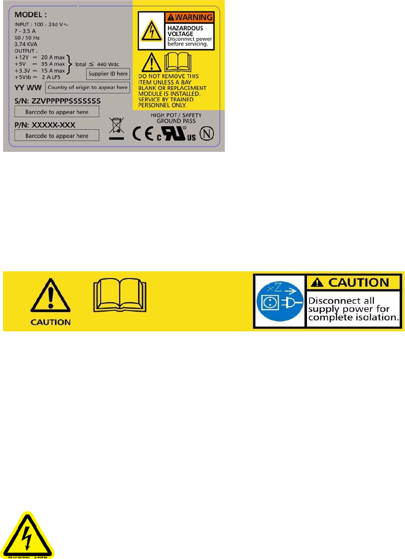
Warning To ensure protection against electric shock caused by HIGH LEAKAGE CURRENT (TOUCH
CURRENT), the SGI InfiniteStorage 15000 must be connected to at least two separate and
independent sources. This is to ensure a reliable earth connection.
• The equipment is intended to operate with two (2) working PCMs. Before removal/replacement of
any module disconnect all supply power for complete isolation.
• A faulty PCM must be replaced with a fully operational module within 24 hours.
Preface
viii 007-5510-002
Power Cooling Module (PCM) Caution Label: Do not operate with modules missing
Warning To ensure your system has warning of a power failure please disconnect the power from the
power supply, by either the switch (where present) or by physically removing the power source,
prior to removing the PCM from the enclosure/shelf.
• Do not remove a faulty PCM unless you have a replacement unit of the correct type ready for
insertion.
PCM Warning Label: Power Hazards
• The power connection must always be disconnected prior to removal of the PCM from the
enclosure.
• A safe electrical earth connection must be provided to the power cord.
• Provide a suitable power source with electrical overload protection to meet the requirements laid
down in the technical specification.
Warning Do not remove covers from the PCM. Danger of electric shock inside. Return the PCM to your
supplier for repair.
PCM Safety Label: Electric Shock Hazard Inside

Preface
007-5510-002 ix
Warning Operation of the Enclosure with ANY modules missing will disrupt the airflow and the drives will
not receive sufficient cooling. It is ESSENTIAL that all apertures are filled before operating the
unit.
•Drive Carrier Module Caution Label: Drive spin down time 30 seconds
Recycling of Waste Electrical and Electronic
Equipment (WEEE)
At the end of the product’s life, all scrap/ waste electrical and electronic equipment should be recycled
in accordance with National regulations applicable to the handling of hazardous/ toxic electrical and
electronic waste materials.
Please contact your supplier for a copy of the Recycling Procedures applicable to your product.
Important Observe all applicable safety precautions, e.g. weight restrictions, handling batteries and lasers
etc., detailed in the preceding paragraphs when dismantling and disposing of this equipment
Rack System Precautions
Important SGI InfiniteStorage 15000 drive enclosures should only be installed in SGI InfiniteStorage 15000
racks. Mounting and installing these drive enclosures in any other rack is not authorized or
supported by SGI.
The SGI InfiniteStorage 15000 drive enclosures are pre-installed in the rack before shipment. If the drive
enclosures must be re-installed and mounted, the following safety requirements must be considered
when the unit is mounted in a rack.
• The rack stabilizing (anti-tip) plates should be installed and secured to prevent the rack from tipping
or being pushed over during installation or normal use.
• When loading a rack with the units, fill the rack from the bottom up and empty from the top down.
• Always remove all modules and drives, to minimize weight, before loading the chassis into a rack.
Warning It is recommended that you do not slide more than one enclosure out of the rack at a time, to avoid
danger of the rack tipping over.
• When mounting in a rack, ensure that the enclosure is pushed fully back into the rack.
Preface
x 007-5510-002
• The electrical distribution system must provide a reliable earth ground for each unit and the rack.
• Each power supply in each unit has an earth leakage current of 1.5mA. The design of the electrical
distribution system must take into consideration the total earth leakage current from all the power
supplies in all the units.
Cover Label
ESD Precautions
Caution It is recommended that you fit and check a suitable anti-static wrist or ankle strap and observe all
conventional ESD precautions when handling plug-in modules and components. Avoid contact with
backplane components and module connectors, etc.
Data Security
• Power down your host computer and all attached peripheral devices before beginning installation.
• Each enclosure contains up to 60 removable disk drive modules. Disk units are fragile. Handle them
with care, and keep them away from strong magnetic fields.
•All the supplied plug-in modules and blanking plates must be in place for the air to flow correctly
around the enclosure and also to complete the internal circuitry.
Preface
007-5510-002 xi
• If the subsystem is used with modules or blanking plates missing for more than a few minutes, the
enclosure can overheat, causing power failure and data loss. Such use may also invalidate the
warranty.
• If you remove any drive module, you may lose data.
–If you remove a drive module, replace it immediately. If it is faulty, replace it with a drive
module of the same type and capacity
• Ensure that all disk drives are removed from the enclosure before attempting to move the rack
installation.
• Do not abandon your backup routines. No system is completely foolproof.
.
Introduction
007-5510-002 1
Chapter 1
Introduction
The SGI InfiniteStorage 15000 controller is an intelligent storage infrastructure device designed and
optimized for the high bandwidth and capacity requirements of IT departments, rich media, and high
performance workgroup applications.
The controller plugs seamlessly into existing SAN environments, protecting and upgrading investments
made in legacy storage and networking products to substantially improve their performance, availability,
and manageability.
The controller’s design is based on an advanced pipelined, parallel processing architecture, caching,
RAID, and system and file management technologies. These technologies have been integrated into a
single plug-and-play device—the SGI InfiniteStorage 15000—providing simple, centralized, and secure
data and SMNP management.
The SGI InfiniteStorage 15000 is designed specifically to support high bandwidth, rich content, and
shared access to and backup of large banks of data. It enables a multi-vendor environment comprised of
standalone and clustered servers, workstations and PCs to access and back-up data stored in centralized
or distributed storage devices in an easy, cost-effective, and reliable manner.
Each controller orchestrates a coherent flow of data throughout the storage area network (SAN) from
users to storage, managing data at speeds of up to 3000 MB/second (or 3 GB/second). This is
accomplished through virtualized host and storage connections, a DMA-speed shared data access space,
and advanced network-optimized RAID data protection and security—all acting in harmony with
sophisticated SAS storage management intelligence embedded within the controller.
The controller can be “coupled” to form data access redundancy while maintaining fully pipelined,
parallel bandwidth to the same disk storage. This modular architecture ensures high data availability and
uptime along with application performance. With its PowerLUN technology, the system provides full
bandwidth to all host ports simultaneously and without host striping.
1.1 Controller Features
The SGI InfiniteStorage 15000 controller incorporates the following features:
•Simplifies Deployment of Complex SANs
The controller provides SAN administration with the management tools required for large number
of clients.
•Infiniband or Fibre Channel (FC-8) Connectivity Throughput
The controller provides up to four (4) individual double data rate four-lane Infiniband or FC-8 host
port connections, including simultaneous access to the same data through multiple ports. Each IB
host port supports point-to-point and switched fabric operation.
•Highly Scalable Performance and Capacity
The RAID engine provides both fault-tolerance and capacity scalability. Performance remains the
same, even in degraded mode. Internal data striping provides generic load balancing across drives.
The RAID engine can support from 10 drives minimum to 1200 drives maximum. Formatable
capacity is drive capacity.
2 007-5510-002
•Comprehensive, Centralized Management Capability
The controller provides a wide range of management capabilities: Configuration Management,
Performance Management, Logical Unit Number (LUN) Management, Security Administration,
and Firmware Update Management.
•Management Options via RS-232 and Ethernet (Telnet)
A RS-232 port and Ethernet port are included to provide local and remote management capabilities.
SNMP is also supported.
•Data Security with Dual-Level Protection
Non-host based data security is maintained with scalable security features including restricted
management access, dual-level protection, and authentication against authorized listing (up to 256
direct host logins per host port are supported). No security software is required on the host
computers.
•Storage Virtualization and Pooling
Storage pooling enables different types of storage to be aggregated into a single logical storage
resource from which virtual volumes can be served up to multi-vendor host computers. Up to 1024
LUNs are supported.
•SES (SCSI Enclosure Services) Support for Enclosure Monitoring
Status information on the condition of enclosure, disk drives, power supplies, and cooling systems
are obtained via the SES interface.
•Absolute Data Integrity and Availability
Automatic drive failure recovery procedures are transparent to users.
•Hot-Swapable and Redundant Components
The controller utilizes redundant, hot-swappable power supplies and a hot swappable fan module
that contains redundant cooling fans.
1.2 The Controller Hardware
The basic controller (See Figure 1–1.) includes:
• A chassis enclosure (with a minimum of 2.56GB cache memory)
• 10 SAS connectors that connect the controller to the drive enclosures
• Connector(s) for host Infiniband or Fibre Channel (FC-8) connection(s)
• Serial connectors for maintenance/diagnostics
• Ethernet RJ-45 connector
Introduction
007-5510-002 3
Figure 1–1 SGI InfiniteStorage 15000 IB - Front and Rear Views
The controller is a high-performance controller designed to be rack-mounted in standard 19" racks. Each
controller is 3.5" in height, requiring 2U of rack space. The system uses 10 independent SAS drive
channels to manage data distribution and storage for up to 120 disk drives per channel (which can be
limited by drive enclosure type).
P
S
PS
G
H
GH
A
B
AB
E
F
EF
C
D
CD
DISK CHANNELS
AC
FAIL
SYSTEM
STATUS
CTRL
STATUS
TEMP
STATUS
DISK
STATUS
DC
STATUS
FAN
STATUS
TEST
STATUS
ACT
HOST 1/2
CLI
HOST 1
HOST 2
1
2
STATUS
ACT
HOST 3/4
CLI
HOST 3
HOST 4
3
4
1/2
TEST PLACE PIN HERE
LINK
ACT MUTE
AC
FAIL
ACT
LINK
ACT
LINK
TELNET
ALARM
SILENCE
CLI
COM
LINK
Front (behind cover panel)
Rear
4 007-5510-002
1.2.1 Power Supply and Fan Modules
Each controller is equipped with two (2) power supply modules and one (1) fan module. The PSU (power
supply unit) voltage operating ranges are nominally 110V to 230V AC, and are autoranging.
The two Power Supply modules provide redundant power. If one module fails, the other will maintain the
power supply and cooling while you replace the faulty module. The faulty module will still be providing
proper air flow for the system so do not remove it until a new module is available for replacement.
The two power supply modules are installed in the lower left and right slots at the front of the unit, behind
the cover panel (Figure 1–1). Each PSU module is held in place by one thumbscrew.
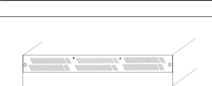
The fan module (Figure 1–1) is installed in the front top slot, behind the cover panel, and held in place
by two thumbscrews.
The two LEDs mounted on the front of the power supply module (located on the right and left of the
power supply handle) indicate the status of the PSU:
• Both LEDs will be lit green when the supply is active and the output is within operating limits with
no faults.
• The left LED indicates the status of the AC input. The LED is lit green as long as the AC input is
present.
• The right LED indicates the status of the DC output of the power supply. The LED is lit green when
the supply is enabled and the outputs are withing specification. The LED will be off when AC input
is not present, the outputs are disabled (after a SHUTDOWN command), or the outputs are not within
specification. A cooling fan failure will not turn this LED off unless the failure results in a thermal
shutdown of the supply.
The AC switch for each supply is located on the rear of the controller unit.
The fan module contains multiple fans for cooling the controller. It is the primary source of cooling and
must be installed at all times during operation (except when it is being replaced due to a faulty fan).
NOTE :
For more information on fan status, see the description of the Status LEDs on rear panel in
the next section.
Figure 1–2 Fan Module (front panel)
Introduction
007-5510-002 5
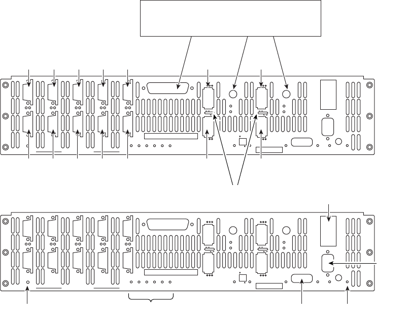
1.2.2 I/O Connectors and Status LED Indicators
Figure 1–3 shows the ports at the back of the controller 4 Infiniband (IB) unit.
Figure 1–3 I/O Ports on the Rear Panel of the Controller
P
S
PS
G
H
GH
A
B
AB
E
F
EF
C
D
CD
DISK CHANNELS
AC
FAIL
SYSTEM
STATUS
CTRL
STATUS
TEMP
STATUS
DISK
STATUS
DC
STATUS
FAN
STATUS
TEST
STATUS
ACT
HOST 1/2
CLI
HOST 1
HOST 2
1
2
STATUS
ACT
HOST 3/4
CLI
HOST 3
HOST 4
3
4
1/2
TEST PLACE PIN HERE
LINK
ACT MUTE
AC
FAIL
ACT
LINK
ACT
LINK
TELNET
ALARM
SILENCE
CLI
COM
LINK
APGEC
BSHFD
Host 3Host 1
Host 4Host 2
Ethernet
AC fail LEDAC fail LED COMStatus LEDs
RS-23
2
interfac
e
IB LEDs
These ports are for the test of the RAID
engine by the manufacturer or other authorized
personnel only.
6 007-5510-002
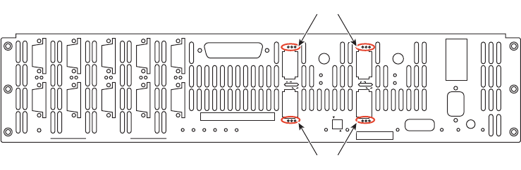
Figure 1–4 Host Port LEDs
The four HOST ports are used for IB or FC-8 host connections. You can connect your host servers IB
HCA port(s) or FC HCA port(s)directly to these ports. Additionally, you can connect these ports to your
IB or FC switches and hubs.
The IB LEDs (the Infiniband LEDs) located between the host ports, when solid green, indicate that
there is physical connectivity with the host; when steady amber, they indicate that the subnet manager
is communicating with the host.
On FC-8 models, the FC LEDs are located next to each FC host port. There are 3 LEDs for each host
port, which indicate if the connection is running at 8 GB (left LED), 4 GB (middle LED), or 2 GB (right
LED). The respective LED will be a solid green to show that there is a physical connection. If the
respective LED is flashing, this indicates data transfer. If the connector is taken from the host port, all 3
LEDs for that port will flash.
The DISK CHANNEL ports ( jackscrew style connectors) are for disk connections. The ten ports are
labeled by data channels (ABCDEFGHPS). Flashing LEDs indicate activity.
The RS-232 connector provides local system monitoring and configuration capabilities and uses a
standard DB-9 null modem female-to-male cable.
The TELNET port provides remote monitoring and configuration capabilities. The ACT (Activity)
LED flashes green when there is Ethernet activity. It is unlit when there is no Ethernet link. The LINK
LED turns green when the link speed is 1000MB/s, amber when the link speed is 100MB/s, and is unlit
when the link speed is 10 MB/s.
The LINK port is used to connect single controller units in order to form a couplet via a cross-over
Ethernet cable. The ACT (Activity) LED flashes green when there is Ethernet activity. The LED is
unlit when there is no Ethernet link. The LINK LED turns green when the link speed is 1000MB/s,
amber when the link speed is 100MB/s, and is unlit when the link speed is 10 MB/s.
The COM port is an RS-232 Interface that uses an RJ-45 cable and connects controller units. The COM
port has two(2) LEDs associated with it: HDD ACT (Activity) and LINK ACT.
The Controller ID Selection Switch (labeled as 1/2) allows the user to configure the units
as Unit 1 or Unit 2. Each unit has an activity LED. It is green for the selected unit. The switch is
comprised of two DIP switches. The first DIP switch (indicated by the 1/2 label ) is used to select the unit
configuration. Flip the switch up for Unit 1---down for Unit 2. When two controller controllers are
paired together to form a couplet, one controller must be configured as unit 1 and its partner must be
configured as unit 2.
P
S
PS
G
H
GH
A
B
AB
E
F
EF
C
D
CD
DISK CHANNELS
AC
FAIL
SYSTEM
STATUS
CTRL
STATUS
TEMP
STATUS
DISK
STATUS
DC
STATUS
FAN
STATUS
TEST
STATUS
ACT
HOST 1/2
CLI
HOST 1
HOST 2
1
2
STATUS
ACT
HOST 3/4
CLI
HOST 3
HOST 4
3
4
1/2
TEST PLACE PIN HERE
LINK
ACT MUTE
AC
FAIL
ACT
LINK
ACT
LINK
TELNET
ALARM
SILENCE
CLI
COM
LINK
Host port LEDs
Host port LEDs

Introduction
007-5510-002 7
There are two AC Fail LEDs. Each LED is connected to its power supply independent of the other
supply. The LEDs are green to indicate that the AC input to the supply is present. The LEDs turn red
if the AC input to the supply is not present. If this occurs, check the LEDs on the front side of the unit.
If you lose AC power from one supply cord, the LED for that supply outlet will turn red.
Figure 1–5 shows the following status LEDs: System, Controller, Disk, Temperature, DC, and Fan.
Figure 1–5 LED Status Indicators - Rear Panel of the Controller
The SYSTEM STATUS LED is solid green when the entire storage system is operating normally.
The CTRL (CONTROLLER) STATUS LED is green when the controller is operating normally
and turns red when the controller unit is failed.
The DISK STATUS LED is green when a disk enclosure is operating normally and turns amber when
there is a problem.
The TEMP STATUS LED is green when the temperature sensors (6 total) indicate that the system is
operating normally, amber when one (1) temp sensor indicates an over-temperature condition, and red
when two (2) or more sensors indicate an over-temperature condition.
The DC STATUS LED is green when indicating normal operating status. It turns amber if there is a
non-critical power Supply DC fault (that is, a power supply is not installed or is not indicating “Power
Good”). It turns red if an on-board supply fails or if there is a critical supply fault. If this occurs, check
the LEDs on the front side of the unit.
The FAN STATUS LED is solid green when fans are operating normally. A flashing green LED
indicates system monitoring activity such that the monitoring is being updated. The LED flashes amber
if one of the fans in the module fails. If 2 or more fans fail, the LED flashes a solid red and the system
will begin the shut down process at 5 seconds, for a total of 30 seconds to complete shutdown.
CTRL
FAN
SYSTEM DC
TEMP
STATUS
STATUS
STATUS STATUS
STATUS
STATUS
DISK

8 007-5510-002
Table 1–1 LED Indicators
Status Indicator Led Activity Explanation
IB Solid Green (Infiniband) Physical Connectivity with host
Solid Amber Subnet Manager communicating with host
DISK ports Flashing Green Activity. There is an LED for each of the ten
ports/channels (ABCDEFGPS)
Unlit
Telnet ACT Flashing Green Activity
Unlit No activity
Telnet LINK (Speed) Solid Green Link Speed=1000 mb/s
Solid Amber Link Speed=100 mb/s
Unlit Link Speed= 0 mb/s
Link ACT Flashing Green Activity
Unlit No activity
Link LINK (Speed) Solid Green Link Speed=1000 mb/s
Solid Amber Link Speed=100 mb/s
Unlit Link Speed=10 mb/s
Com Port HDD ACT Open
Com Port LINK ACT Open
Host 1/2 CLI STATUS Open
Host 1/2 CLI STATUS Open
Host 3/4 CLI ACT Open
Host 3/4 CLI ACT Open
System Solid Green System is operating normally
Ctrl Solid Green System is operating normally
Solid Amber System is shutting down

Introduction
007-5510-002 9
1.2.3 Uninterruptible Power Supply (UPS)
Using an Uninterruptible Power Supply (UPS) with the controller is highly recommended. The UPS can
guarantee power to the system in the event of a power failure for a short time, which will allow the system
to power down properly.
SGI offers two types of UPS: basic and redundant. The basic UPS is rack-mountable. It can maintain
power to a five (5) enclosure system for seven (7) minutes while the system safely shuts down during a
power failure. The redundant UPS contains power cells that provide a redundant UPS solution.
NOTE :
The UPS should be installed by a licensed electrician. Contact SGI to obtain circuit and
power requirements.
Status Indicator Led Activity Explanation
Disk Solid Green All related disk enclosures are operating
normally
Solid Amber There is a problem with 1 or more of the disk
enclosures
Temp Status Solid Green All temp sensors operating normally
Solid Amber At least 1 temp sensor has reported over-
temperature conditions
Solid Red 2 or more temp sensors has reported over-
temperature condition
DC Solid Green Operating normally
Solid Amber Non-critical power supply fault
Solid Red Critical power supply fault
Fan Status Solid Green Operating normally
Flashing Green System monitoring activity
Flashing Amber 1 fan has failed and needs to be replaced
Solid Red 2 or more fans have failed or are undetected and
the system will shutdown in 30 seconds
AC Fail Solid Green Operating normally
Solid Red Power input to supply not present. AC failure
FC (FC-8 only) Solid Physical connection has been made.
Flashing Data is being transferred.
Table 1–1 LED Indicators
Controller Installation
007-5510-002 11
Chapter 2
Controller Installation
These steps provide an overview of the controller installation process. The steps are explained in detail
in the following sections of this chapter.
1. Unpack the controller system.
2. If it is necessary to install the controller in the 19-inch cabinet(s), contact your service provider.
NOTE :
Most controller configurations arrive at sites pre-mounted in a 42U or 45U rack supplied by
SGI.
3. Set up and connect the drive enclosures to the controller.
4. Connect the controller to your Infiniband (IB) or Fibre Channel (FC) switch and host computer(s).
5. Connect your RS-232 terminal to the controller.
6. Power up the system.
7. Configure the storage array (create and format LUNs - Logical Units) via RS-232 interface, Telnet,
or GUI.
8. Define and provide access rights for the clients in your SAN environment. Shared LUNs need to be
managed by SAN management software. Individual dedicated LUNs appear to the client as local
storage and do not require management software.
9. Initialize the system LUNs for use with your server/client systems. Partition disk space and create
file systems as needed.
2.1 Setting Up the Controller
This section details the installation of the hardware components of the controller system.
NOTE :
Follow the safety guidelines for rack installation given in the “Preface”.
The SGI InfiniteStorge 15000 must be removed from the shipping pallet using a
minimum of 4 people. The racked unit may not be tipped more than 10 degrees,
either from a level surface or rolling down an incline (such as a ramp).
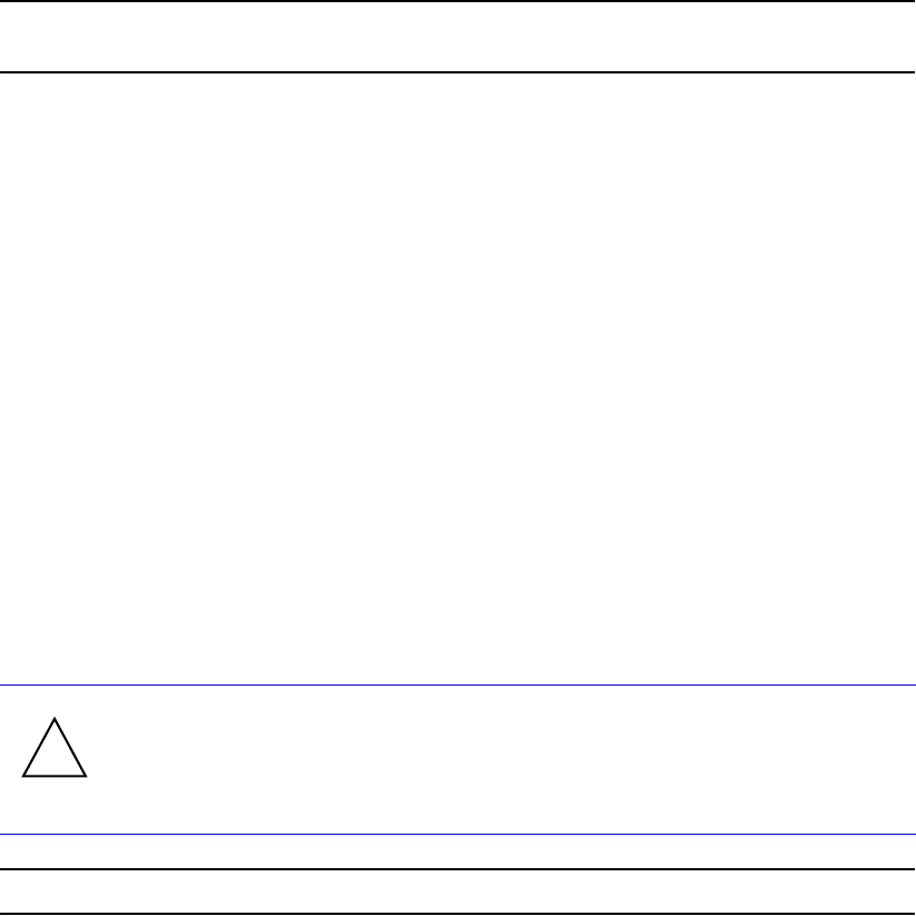
!
Warning

Controller Installation
12 007-5510-002
2.2 Unpacking the System
Before you unpack your controller, inspect the shipping container(s) for damage. If you detect damage,
report it to your carrier immediately. Retain all boxes and packing materials in case you need to store or
ship the system in the future.
While removing the components from their boxes/containers, inspect the controller chassis and all
components for signs of damage. If you detect any problems, contact SGI immediately.
Your controller ships with the following:
• controller chassis
• two (2) power cords
• RS-232 and Ethernet cables for monitoring and configuration
• cover panel and rack-mounting hardware
2.2.1 Rack-Mounting the Controller Chassis
For instructions on mounting the controller in the rack, contact your service provider.
2.2.2 Connecting the Controller in Dual Mode
For dual mode configuration only:
1. Connect the LINK ports on the two controller units using the supplied cable.
2. Connect the COM ports on the two units using the supplied cable.
Wear an ESD wrist strap or otherwise ground yourself when handling controller
modules and components. Electrostatic discharge can damage the circuit boards.
!
Warning
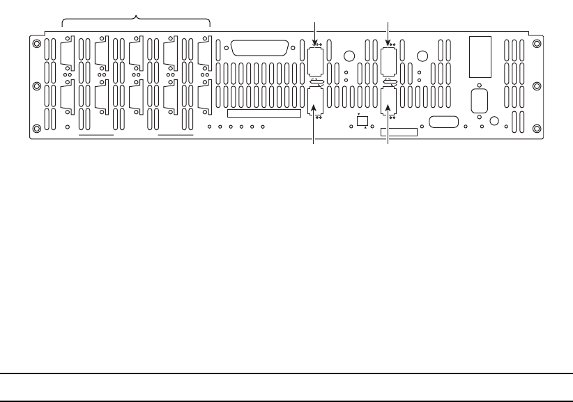
Controller Installation
007-5510-002 13
2.2.3 Connecting the Controller
To set up the disk enclosures and connect them to the controller, do the following.
1. There are 10 disk channels on the controller. They correspond with disk ports. The disk ports are
labeled as follows (Figure 2–1):
DISK A = Channel A DISK B = Channel B
DISK C = Channel C DISK D = Channel D
DISK E = Channel E DISK F = Channel F
DISK G = Channel G DISK H = Channel H
DISK P = Channel P (parity)
DISK S = Channel S (spare)
Using the 10 copper SAS cables provided, connect these disk ports to your ten disk channels.
Figure 2–1 I/O Connectors
2. Each controller supports up to four host connections. You may connect more than four client
systems to the controller using switches and you can restrict user access to the LUNs (as described
in Section 2.3 "Configuring the Controller" of this guide).
The Host ports are numbered 1 through 4 as shown in Figure 2–1. Connect your host system(s) or
switches to these ports. For FC-8 models, ensure that the latches on the transceivers are engaged.
2.2.4 Selecting SAS- ID for Your Drives
NOTE :
The controller uses a select ID of 1.
2.2.5 Laying Out your Storage Drives
Tiers, or RAID groups, are the basic building blocks of the controller. A tier can be catalogued as 8+1
or 8+2. In 8+1 mode, a tier contains 10 drives—eight (8) data drives (Channels A through H), one parity
drive (Channel P), and one optional spare drive (Channel S). In 8+2 mode, a tier contains 10 drives—
eight (8) data drives (Channels A through H) and two parity drives (Channel P and S).
The controller can manage up to 120 tiers.
P
S
PS
G
H
GH
A
B
AB
E
F
EF
C
D
CD
DISK CHANNELS
AC
FAIL
SYSTEM
STATUS
CTRL
STATUS
TEMP
STATUS
DISK
STATUS
DC
STATUS
FAN
STATUS
TEST
STATUS
ACT
HOST 1/2
CLI
HOST 1
HOST 2
1
2
STATUS
ACT
HOST 3/4
CLI
HOST 3
HOST 4
3
4
1/2
TEST PLACE PIN HERE
LINK
ACT MUTE
AC
FAIL
ACT
LINK
ACT
LINK
TELNET
ALARM
SILENCE
CLI
COM
LINK
Host port 3Host port 1
Host port 4Host port 2
Disk ports
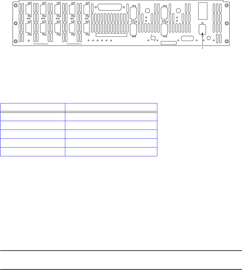
Controller Installation
14 007-5510-002
Configuration of disks in the enclosures must be in sets of complete tiers (Channels A through P).
Allocating one spare drive per tier gives you the best data protection but this is not required. The spare
drives on the controller are global hot spares.
2.2.6 Connecting the RS-232 Terminal
For first time set-up, you will need access to an RS-232 terminal or terminal emulator (such as Windows
hyperterminal). Then you may set up the remote management functions and configure/monitor the
controller remotely via Telnet.
1. Connect your terminal to the CLI port at the back of the controller using a standard DB-9 female-
to-male null modem cable (Figure 2–2).
Figure 2–2 Controller CLI Port
2. Open the terminal window.
3. Use the following settings for your serial port:
2.2.6.1 Basic Key Operations
The command line editing and history features support ANSI and VT-100 terminal modes. The
command history buffer can hold up to 64 commands. The full command line editing and history only
work on main CLI and telnet sessions when entering new commands. Basic Key Assignments are listed
in Table 2–1 on page 15.
Simple, not full command, line editing only is supported when the:
• CLI prompts the user for more information.
• alternate CLI prompt is active. (The alternate CLI is used on the RS-232 connection during an active
telnet session.)
NOTE :
Not all telnet programs support all the keys listed in Table 2–1 "Basic Key Assignments".
The Backspace key in the terminal program should be setup to send ‘Ctrl-H’.
Setting Value
Bits per second: 115,200
Data bits: 8
Parity: None
Stop bits: 1
Flow Control: None
P
S
PS
G
H
GH
A
B
AB
E
F
EF
C
D
CD
DISK CHANNELS
AC
FAIL
SYSTEM
STATUS
CTRL
STATUS
TEMP
STATUS
DISK
STATUS
DC
STATUS
FAN
STATUS
TEST
STATUS
ACT
HOST 1/2
CLI
HOST 1
HOST 2
1
2
STATUS
ACT
HOST 3/4
CLI
HOST 3
HOST 4
3
4
1/2
TEST PLACE PIN HERE
LINK
ACT MUTE
AC
FAIL
ACT
LINK
ACT
LINK
TELNET
ALARM
SILENCE
CLI
COM
LINK
CLI (RS-232 Interface)
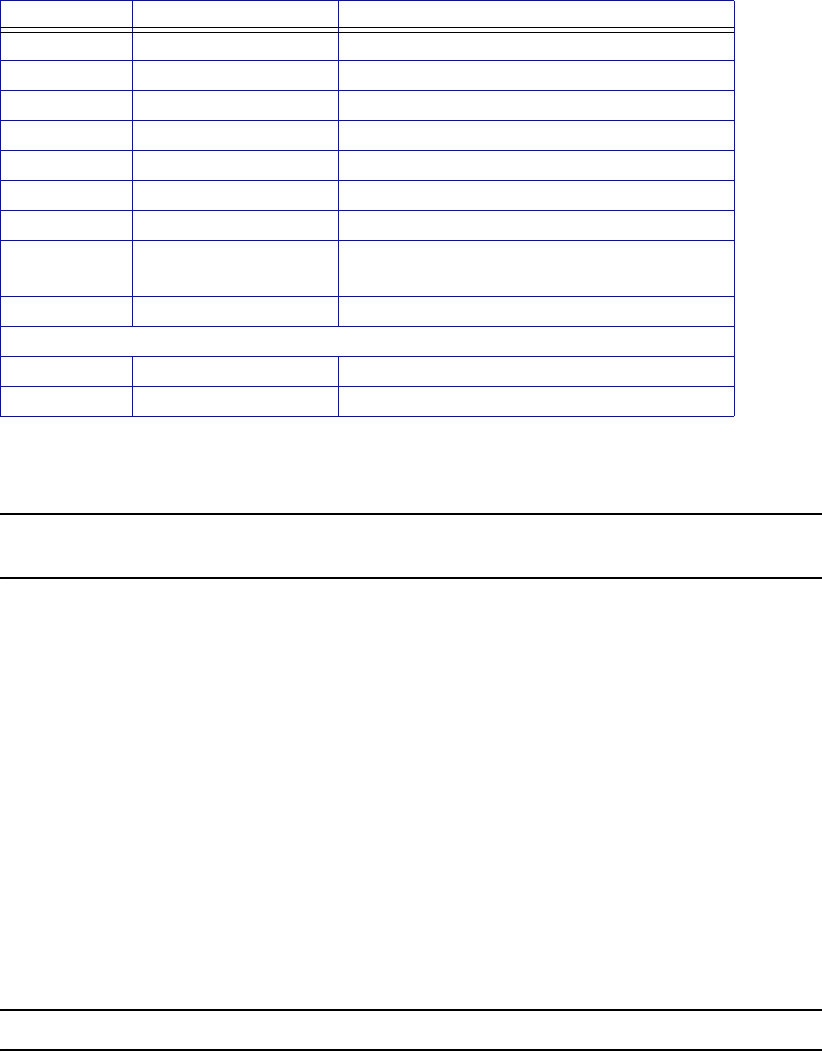
Controller Installation
007-5510-002 15
2.2.7 Powering On the Controller
NOTE :
Systems that have dual controllers (couplets) should have the controllers powered on
simultaneously ensure correct system configuration.
1. Verify that the power switches on the two (2) power supply module at the back of each controller
are off.
2. Connect the two AC connectors, using the power cords provided at the back to the AC power
source for each controller unit. For maximum redundancy, connect the two power connectors to
two different AC power circuits for each unit.
3. Check that all your drive enclosures are powered up.
4. Check that the drives are spun up and ready.
5. Turn on the power supplies on the controller unit(s). The controller will undergo a series of system
diagnostics and the bootup sequence is displayed on your terminal.
6. Wait until the bootup sequence is complete and the controller system prompt is displayed.
NOTE :
Do not interrupt the boot sequence without guidance from SGI support personnel.
You may now configure the system as described in Section 2.3 "Configuring the Controller".
Table 2–1 Basic Key Assignments
Key Escape Sequence Description
Backspace Ctrl-H, 0x08 deletes preceding character
Del Del, 0x7F or Esc [3~ deletes current character
Up Arrow Esc [A retrieves previous command in the history buffer
Down Arrow Esc [B retrieves next command in the history buffer
Right Arrow Esc [C moves cursor to the right by one character
Left Arrow Esc [D moves cursor to the left by one character
Home Esc [H or Esc [1~ moves cursor to the start of the line.
End Esc [K or
Esc [4~
moves cursor to the end of the line
Ins Esc [2~ toggles character insert mode, on and off
NOTE: Insert mode is ON by default and resets to ON for each new command.
PgUp Esc [5~ retrieves oldest command in the history buffer
PgDn Esc [6~ retrieves latest command in the history buffer
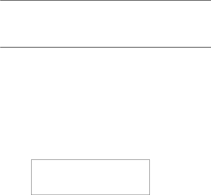
Controller Installation
16 007-5510-002
2.3 Configuring the Controller
This section provides information on configuring your controller.
NOTE :
The configuration examples provided here represent only a general guideline. These
examples should not be used directly to configure your particular controller.
The CLI (command line interface) commands used in these examples are fully
documented in sections 3.1 through 3.8—though exact commands may change depending
on your firmware version. To access the most up-to-date commands, use the CLI’s online
HELP feature.
2.3.1 Planning Your Setup and Configuration
Before proceeding with your controller configuration, determine the requirements for your SAN
environment, including the types of I/O access (random or sequential), the number of storage arrays
(LUNs) and their sizes, and user access rights.
The controller uses either an 8+2 or an 8+1+1 parity scheme. It is a unique implementation that combines
the virtues of RAID 3, RAID 0, and RAID 6 (Figure 2–3). Like RAID 3, a dedicated parity drive is used
per 8+1 parity group; two parity drives are dedicated in the case of an 8+2 parity group or RAID 6. A
parity group is also known as a Tier.
This RAID implementation exhibits RAID 3 characteristics such as tremendous large block-transfer—
READ and WRITE—capability with NO performance degradation in crippled mode. This capability
also extends to RAID 6, delivering data protection against a double disk drive failure in the same tier with
no loss of performance.
Figure 2–3 Striping Across Tiers - RAID
However, Like RAID 5, this RAID implementation does not lock drive spindles and does allow the disks
to re-order commands to minimize seek latency, and the RAID 0-like functionality allows multiple tiers
to be striped, providing “PowerLUNs” that can span hundreds of disk drives. These PowerLUNs support
very high throughput and have a greatly enhanced ability to handle small I/O (particularly as disk
spindles are added) and many streams of real-time content.
LUNs can be created on just a part of a tier, a full tier, across a fraction of multiple tiers, or across multiple
full tiers. A minimum configuration for tiers of drives require either 9 drives in an 8+1 configuration or
10 drives in an 8+2 configuration. When configured in 8+1+1 mode, the tenth data segment is reserved
for global hot spare drives. When configured in 8+2 mode, spares may reside on each data segment and
are global only to that data segment.
Tier Configuration
Space Available
(Mbytes)Tier Disk Status Lun List
Capacity
(Mbytes)
ABCDEFGHPS
------------------------------------------------------------
2718202800121
ABCDEFGHPS2718202800122
ABCDEFGHPS2718202800123
0
0
0
---------------->
Parity Protection within same tier
----------->
Striping
across tiers
when a LUN
is created
across
multiple tiers

Controller Installation
007-5510-002 17
The controller supports various disk drive enclosures that can be used to populate the 10
<ABCDEFGHPS> disk channels in both SAS 1x and SAS 2x modes. Each chassis has a limit to the tiers
that can be created and supported. Refer to the specific disk enclosure user guides for further information.
You can create up to 1024 LUNs in a controller. LUNs can be shared or dedicated to individual users,
according to your security level setup, with Read or Read/Write privileges granted per user. Users only
have access to their own and “allowed-to-share” LUNs. Shared LUNs need to be managed by SAN
management software. Individual dedicated LUNs appear to users as local storage and do not require
external management software.
NOTE :
In dual mode, LUNs are “owned” by the controller unit on which they are created. Hosts only
see the LUNs on the controller to which they are connected, unless cache coherency is enabled.
For random I/O applications, use as many tiers as possible and create one or more LUNs. For
applications that employ sequential I/O, use individual or small grouping of tiers. If you need guidance
in determining your requirements, contact SGI support.
2.3.2 Configuration Interface
You can use the Command Line Interface (CLI) to configure the controller system. This user guide
provides information for setup using the CLI.
2.3.3 Login as Administrator
The default Administrator account name is admin and its default password is password. (See
Section 3.1.3 "Administrator and User Logins" for information on how to change the user and
administrator passwords.) Only users with administrator rights are allowed to change the configuration.
To login:
1. At the login prompt, type:
login admin<Enter>
2. At the password prompt, type:
password<Enter>
2.3.4 Setting System Time & Date
The system time and date for the controller are factory-configured for the U.S. Pacific Standard Time
(PST) zone. If you are located in a different time zone, you need to change the system date and time so
that the time stamps for all events are correct. In dual mode, changes should always be made on Unit 1.
New settings are automatically applied to both units.
To set the system date, at the prompt, type:
date mm dd yyyy <Enter>
where mm represents the two digit value for month, dd represents the two digit value for day, and yyyy
represents the four digit value for year.
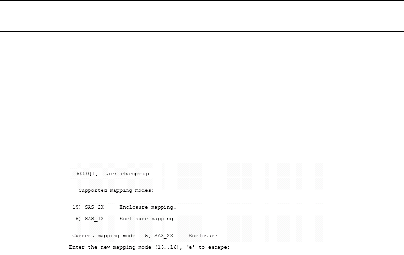
Controller Installation
18 007-5510-002
For example, to change the system date to March 1, 2009, enter:
date 3 1 2009<Enter>
To set the system time, at the prompt, type:
time hh:mm:ss<Enter>
where hh represents the two digit value for hour (00 to 24), mm is the two digit value for minutes, and
ss represents the two digit value for seconds
For example, to change the system time to 2:15:32 p.m., enter:
time 14:15:32<Enter>
NOTE :
The system records time using the military method, which records hours from 00 to 24, not
in a.m. and p.m. increments of 1 to 12.
2.3.5 Setting Tier Mapping Mode
When the controller system is first configured, it is necessary to select a tier mapping mode for the
attached enclosures.
The controller currently supports SAS drive enclosures.
To display the current mapping mode, type: tier map<Enter>.
Figure 2–4 Tier Changemap Screen
To change the mapping mode (Figure 2–4):
1. Enter: tier changemap<Enter>
2. Enter the appropriate mapping mode.
•For 10 and 20 box solutions, choose SAS_2X.
•For 5 box solutions, choose SAS_1X.
3. For the changes to take effect, enter: restart<Enter>.
Controller Installation
007-5510-002 19
2.3.6 Checking Tier Status and Configuration
Use the tier command to display your current tier status. Figure 2–5 illustrates the status of a system
containing 80 drives on 8 tiers with both parity modes of 8+1 and 8+2 tiers. The plus sign (+) adjacent
to the tier number indicates that the tier is in 8+2 mode.
Figure 2–5 Tier Status Screen
Each letter under the “Disk Status” column represents a healthy drive at that channel (as shown in Figure
2–5). Verify that all drives can be seen by the controller.
“Unhealthy” drives appear as follows:
• A blank space indicates that the drive is not present (or detected) at that location.
• A period (.) denotes that the disk was failed by the system.
• A question mark (?) indicates that the disk has failed the diagnostics tests or is not configured
correctly.
• The character “r” indicates that the disk at that location is being replaced by a spare drive.
After entering the tier command, perform the following steps if necessary:
1. If a drive is not displayed at all (that is, it is “missing”), check to ensure that the drive is properly
seated and in good condition. To search for the drive, enter:
disk scan<Enter>
2. If the same channel is missing on all tiers, check the cable connections for that channel.
3. If “automatic disk rebuilding” is not enabled, enable it by entering:
tier autorebuild=on<Enter>
4. To display the detailed disk configuration information for all of the tiers (Figure 2–6) enter:
tier config<Enter>
Tier Status
Space Available
(Mbytes)Tier Disk Status Lun List
Capacity
(Mbytes)
ABCDEFGHPS
-----------------------------------------------------------------
280012280012 1 +
ABCD FGHPS2800122800122
ABCDEFGHPS2800122800123
Automatic disk rebuilding is Enabled
15000 [1]: tier
ABCDEFGHPS2800122800124
AB.DEFGHPS2800122800125
System rebuild extend: 32 Mbytes
System rebuild delay: 60
System Capacity 2240096 Mbytes, 2240096 Mbytes available.
Owner
1
1
1
1
1
ABCDEFGHPS280012280012 6 + 1
ABCDEFG?PS2800122800127 1
ABCDEFGHPS280012280012 8 + 1
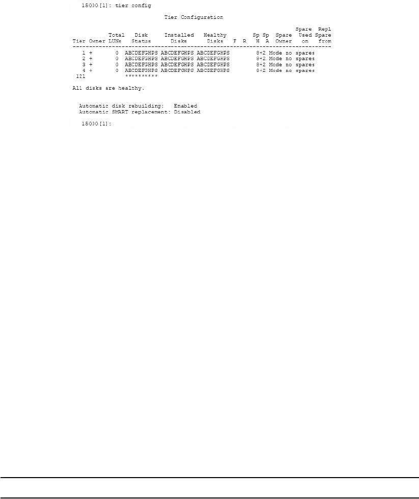
Controller Installation
20 007-5510-002
Figure 2–6 Current Tier Configuration
2.3.6.1 Heading Definitions
•Total LUNs. LUNs that currently reside on the tier.
•Healthy Disk. The “health” of the spare disk currently being used (if any is being used) to replace
a disk on the listed tier. The health indication for the spare channel that is physically on the listed
tier is found under SP H.
•F indicates the failed disk (if any) on the tier.
•R indicates the replaced disk (if any) on the tier.
•Sp H indicates if the spare disk that is physically on the tier is healthy.
•Sp A indicates if the spare disk that is physically on the tier is available for use as a replacement.
•Spare Owner indicates the current owner of the physical spare, where ownership is assigned when
the spare is used as a replacement. “RES-#” will appear under the Spare Owner heading while a
replacement operation is underway to indicate that unit “#” currently has the spare reserved.
•Spare Used on indicates the tier (if any) where this physical spare is being used as a replacement.
•Repl Spare from indicates the tier (if any) whose spare disk is being used as a replacement for this
tier.
NOTE :
Tiers are 8+1 mode by default.
2.3.7 Cache Coherency and Labeling in Dual Mode
Use the DUAL command to check the status of the units that are healthy and verify that the “Dual”
(COM2) and “Ethernet” (LINK) communication paths between the two controller units are established
(Figure 2–7).
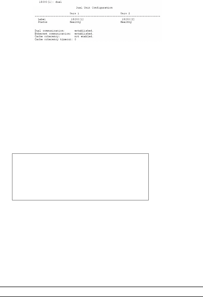
Controller Installation
007-5510-002 21
Figure 2–7 Dual Controller Configuration
If you require multi-pathing to the LUNs, enable cache coherency. If you do not require multi-pathing,
disable cache coherency.
To enable/disable the cache coherency function, enter the following (ON enables, OFF disables):
dual coherency=on|off<Enter>
You may change the label assigned to each unit. This allows you to uniquely identify each unit in the
system. Each unit can have a label of up to 31 characters long.
1. To change the label, enter:
dual label<Enter>
2. Select which unit you want to re-label (see Figure 2–8).
3. When prompted, type in the new label for the selected unit. The new name is displayed.
Figure 2–8 Labeling a Controller Unit
2.3.8 Configuring the Storage Arrays
When you have determined your array configuration, you need to create and format the LUNs. You have
the option of creating a 32-bit or a 64-bit address LUN.
In the example below, 2 LUNs (32-bit addressing) are created:
• LUN 0 on Tiers 1 to 8 with capacity of 8192MB each.
• LUN 1 on Tiers 1 and 2 with capacity of 8192MB each.
NOTE :
You may press e at any time to exit and cancel the command completely.
Enter the number of the Unit you wish to rename.
15000 [1]: dual label
LABEL=1 for Unit 1, Test System[1]
LABEL=2 for Unit 2, Test System[2]
Unit: 1
Enter a new label for Unit 1, or DEFAULT to return to the default label.
Up to 31 characters are permitted.
Current Unit name: Test System[1]
New Unit name: System[1]
15000 [1]:

Controller Installation
22 007-5510-002
NOTE :
In dual mode, LUNs are “owned” by the controller unit where they are created. Hosts only
see the LUNs on the unit to which that they are connected, unless cache coherency is enabled.
1. To display the current cache settings, type: cache<Enter>
2. Select a cache segment size for your array. For example, to set the segment size to 128KBytes,
type:
cache size=128<Enter>
This setting can also be adjusted on-the-fly for specific application tuning: see section 3.2.12
"Couplet Controller Configuration (Cache/Non-Cache Coherent)". The default setting is 1024.
3. Type: lun<Enter>.
The Logical Unit Status chart should be empty, as no LUN is present on the array.
4. To create a new LUN, type: lun add=x<Enter>
where X is the LUN number. Valid LUN numbers are 0..1023.
If only lun add is entered, you are prompted to enter a LUN number.
5. You will be prompted to enter the parameter values for the LUN. In this example:
- Enter a label for the LUN (you can include up to 12 characters). The label may be changed later
using the LUN LABEL command.
- Enter the capacity (in Mbytes) for a single LUN in the LUN group: 8192<Enter>
- Enter the number of tiers to use: 8<Enter>
- Select the tier(s) by entering the Tier number. Enter each one on a new line. Tiers are numbered
from 1 through 125.
1 <Enter>
2 <Enter>
3 <Enter>
4 <Enter>
5 <Enter>
6 <Enter>
7 <Enter>
8 <Enter>
- Enter the block size in Bytes: 512<Enter>
NOTE :
512 is the recommended block size. A larger block size may give better performance.
However, verify that your OS and file system can support a larger block size before changing the block
size from its default value.
This message will display: Operation successful: LUN 0 added to the system
6. When you are asked to format the LUN, type: y<Enter>
Controller Installation
007-5510-002 23
After you have initiated LUN format, the message Starting Format of LUN is displayed.
You can monitor the format progress by entering the command LUN (see Figure 2–9).
Upon completion, this message: Finished Format of LUN 0 displays.
Figure 2–9 Logical Unit Status - Formatting
7. Enter the command LUN to check the status of the LUN, which should be “Ready” (see Figure 2–
10).
Figure 2–10 LUN Status - Ready
8. To create the LUN 1, type:
lun add=1<Enter>
9. Enter these parameters:
- Enter a label for the LUN 1
- For capacity, enter the value in MBytes: 8192 <Enter>
- Enter the number of tiers to use: 2<Enter>
- Select the tier(s) by entering the Tier number. Enter each one on a new line and press the <Enter>
key. The tiers are numbered from 1 through 125.
1 <Enter>
2 <Enter>
- Enter the block size in Bytes: 512<Enter>
- When asked to format the LUN, type: y<Enter>
NOTE :
LUN format is a background process and you can start adding the next LUN as soon as the
format for the previous LUN has started.
Logical Unit Status
Block
Size
LUN Owner Tier ListCapacity
(Mbytes)
512
------------------------------------------------------------------------------
8192Format 14%0
System Capacity 2240096 Mbytes, 2207328 Mbytes available.
Status
1 1 2 3 4 5 6 7 8
15000 [1]: lun
Tiers
8
Label
Logical Unit Status
Block
Size
LUN Owner Tier ListCapacity
(Mbytes)
512
------------------------------------------------------------------------------
8192Ready0
System Capacity 2240096 Mbytes, 2207328 Mbytes available.
Status
1 1 2 3 4 5 6 7 8
15000 [1]: lun
Tiers
8
Label

Controller Installation
24 007-5510-002
2.3.9 Setting Security Levels
After you have formatted all the LUNs, you can define users’ access rights. Configurations come in two
types:
• authorized user
• host port zoning
The Authorized User configuration is highly recommended for use in a SAN environment-- your data
is completely secured and no accidental plug-in is allowed to do damage such as data change or deletion.
Authorized users have access only to their own and “allowed to share” data. Administrators can also
restrict users’ access to the host ports and their read/write privileges to the LUNs. Another advantage of
this configuration is that the users see the same LUN identification scheme regardless of the host port
connection.
The Host Port Zoning configuration provides the minimum level of security. The LUN mappings
change according to the host port connection. The read-only and read/write privileges can be specified
for each LUN.
The place holder LUN feature allows the controller administrator to map a zero-capacity LUN to a host
or group of hosts (via zoning or user authentication). The administrator can then create a real LUN and
map it to the host(s) to replace the place holder LUN in the future. In most cases, the host does not have
to reboot since it already mapped to the place holder LUN.
NOTE :
Support of place holder LUNs is dependent upon the OS (operating system), the driver, and
the Host Card Adapter (HCA-IB), or Host Bus Adapter.
2.3.9.1 User Authentication (Recommended for SAN Environment)
Each user connected to the controller is identified by a World Wide Name (WWN) or GUID, and is
given a unique user ID number. The controller can store configurations for up to 512 users and the
security settings apply to all host ports.
Below is an example for adding two users to a system containing two LUNs (numbered 0 and 1). Each
user has an internal LUN 1 is shared and “read-only.” Both users see the shared LUN as LUN 0 and they
see their own LUN as LUN 1. User 1 has access to host ports 1 and 4 while User 2 only has access to
host port 2.
Prior to adding any users, verify that no “anonymous” access is allowed to the system:
1. Enter: zoning<Enter>

Controller Installation
007-5510-002 25
2. Check to ensure that the LUN Zoning chart is empty (Figure 2–11).
Figure 2–11 LUN Zoning Screen
To add a user:
1. Type: user audit=on<Enter> The controller reports which users are connected.
2. Type: user add<Enter>.
3. Specify a new Host User’s world wide name, enter s.
4. Specify a 64-bit world wide name or GUID, taken from the list of available anonymous users.
5. Enter an alias name for the user. The name may contain up to 12 characters. Type in a name and
press <Enter>.
6. Host users can have their port access zoned. Enter y to specify host port zoning.
7. For Unit 1, enter each active port on a new line and then exit. For this example, type:
1<Enter>
4<Enter>
e<Enter>
8. For Unit 2, enter each active port on a new line and then exit. For this example, type:
1<Enter>
4<Enter>
e<Enter>
Host users are limited to accessing specific LUNs, as follows:
• a host user may have its own unique LUN mapping, or
• a host user may use the anonymous LUN mapping.
The anonymous user LUN mapping is handled by the port ZONING command. In either case, the LUN
mapping applies on all the ports for which the user has been zoned.
9. Enter y to specify the unique LUN mapping (Table 2–2).
LUN Zoning
-----------------------------------------------------------------------------
15000 [1]: zoning
World Wide NamePort External LUN, Internal LUN
1 21000001FF040004
2 22000001FF040004
3 23000001FF040004
4 24000001FF040004
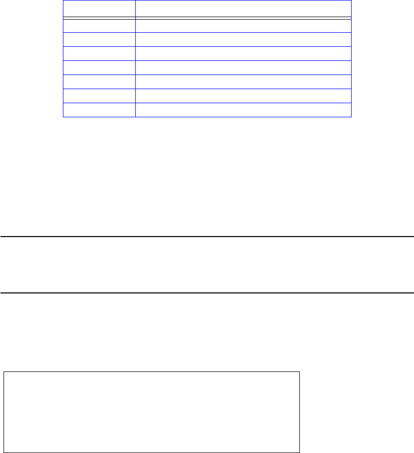
Controller Installation
26 007-5510-002
10. Enter a new unique LUN mapping for this user. Options are shown in Table 2–2 on page 26.
11. Connect user 2 and repeat steps 2--10 to specify the host port zoning and LUN mappings with the
following changes:
- For active host port (step 6), enter port 2 only.
- For LUN mapping:
External LUN 0 is mapping to internal LUN: R1
External LUN 1 is mapping to internal LUN: 1
External LUN 2 is mapping to internal LUN: q
NOTE :
In this scheme, users 1 and 2 have their own custom LUN identification scheme. The internal
LUN 1 that is shared by the users needs to be managed by SAN management software.
The individual dedicated LUN appears to the user as local storage and does not require
external management software.
12. To display the new security settings, type:
user<Enter>.
Figure 2–12 shows a finished sample.
Figure 2–12 Security Settings Screen
Table 2–2 LUN Mapping Options.
Option Description
G.1 GROUP.LUN number
P place-holder
R Read-Only. Place before the GROUP.LUN
N Clear current assignment
<cr> No Change
EEXIT
? Display detailed help text.
15000 [1]: user
LUN Zoning
-------------------------------------------------------------------------------
User
210000E08B057383000 client1
World Wide Name
1 4
User auditing is enabled.
External LUN, Internal LUN
Ports
12
R000,001 001,0
210000E08B028233128 client2 2 R000,001 001,1

Controller Installation
007-5510-002 27
2.3.9.2 Host Port Zoning (Anonymous Access)
Host Port Zoning (Anonymous Access) should only be used for non-SAN environment. Users are given
“general admission” to the data.
One zoning configuration is supported for each of the host ports. Any unauthorized user accessing the
storage is considered “anonymous” and granted zoning access for the host port to which they are
connected. Given below is an example for adding LUN zoning to host port 1. External LUN 1 is mapped
to internal LUN 0 and it is read-only for the users.
1. To edit the default zoning on a host port, type: zoning edit<Enter>. The current settings are
displayed.
2. Select a host port (1..4): 1<Enter>
3. Specify the internal LUN (0..1023) to be mapped to the external LUN. The new settings will display
.
4. Repeat steps 1–3 to configure other host ports.
Anonymous Access (host port zoning) provides only the minimum level of
security.
!
Warning
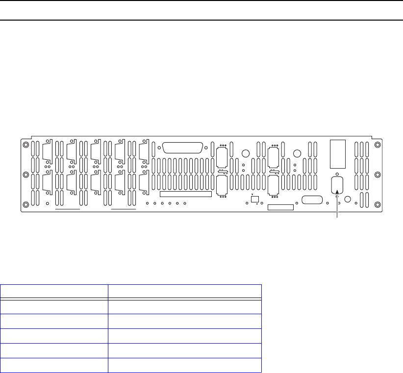
Controller Management
007-5510-002 29
Chapter 3
Controller Management
3.1 Managing the Controller
The controller provides a set of tools that enable administrators to centrally manage the network storage
and resources that handle business-critical data. These include Configuration Management, Performance
Management, Remote Login Management, Security Administration, and Firmware Update
Management. Bundled together, this is called the controller’s Administrator Utility.
3.1.1 Management Interface
SAN management information for the controller can be accessed locally through a serial interface, or
remotely through Telnet.
NOTE :
A controller may have only one active login (serial or Telnet) at any given time.
Locally - Serial Interface
Any RS-232 terminal or terminal emulator (such as Microsoft Windows HyperTerminal) can be used to
configure and monitor the controller.
1. Connect your terminal to the CLI port at the back of the controller using a standard DB-9 female-
to-male null modem cable (Figure 3–1).
Figure 3–1 Controller CLI Port
2. Open your terminal window and use these settings for your serial port:
Setting Value
Bits per second: 115,200
Data bits: 8
Parity: None
Stop bits: 1
Flow Control: None
P
S
PS
G
H
GH
A
B
AB
E
F
EF
C
D
CD
DISK CHANNELS
AC
FAIL
SYSTEM
STATUS
CTRL
STATUS
TEMP
STATUS
DISK
STATUS
DC
STATUS
FAN
STATUS
TEST
STATUS
ACT
HOST 1/2
CLI
HOST 1
HOST 2
1
2
STATUS
ACT
HOST 3/4
CLI
HOST 3
HOST 4
3
4
1/2
TEST PLACE PIN HERE
LINK
ACT MUTE
AC
FAIL
ACT
LINK
ACT
LINK
TELNET
ALARM
SILENCE
CLI
COM
LINK
CLI (RS-232 Interface)

30 007-5510-002
3. With the controller ready, press <Enter> to get the controller prompt.
NOTE :
To change the baud rate on controller, see section 3.8.3 "Changing Baud Rate for the CLI
Interface" in this guide.
Remotely - Telnet
To configure and monitor the controller remotely, connect the controller to your Ethernet network. Refer
to Section 4.1, "Remote Management of the Controller" for information on how to set up the controller’s
network interface.
3.1.2 Available Commands
Use the Help command to display the available commands within the utility. To get help information on
a command, type the command followed by a question mark.
For example, type: cache?<Enter>
to display help on cache options on the system.
3.1.3 Administrator and User Logins
The login command allows the user to log into a (new) terminal or Telnet session at a specific security
user level—administrative or general purpose. You will need Administrator access on the controller in
order to change the system configurations.
For RS-232 terminal session, the general purpose user does not require login. For a Telnet session, you
are required to login as either an administrator or a general purpose user. If you login as an administrator,
you will have access to all the management and administrative functions. You can obtain status
information and make changes to the system configuration.
At the general purpose user access level, you are only allowed to view status and configuration
information. If the controller determines that the individual does not have the proper privileges, it will
return a message (where the “user entered command” represents a command keyed in by the user):
<user entered command>: Permission denied
3.1.3.1 Login
To login to the system, do the following:
1. To login (Figure 3–2), enter: login<Enter>
The prompt will display Enter a login name:
2. Enter a login name.
This prompt will display Enter the password:
3. Enter a password (see Figure 3–2).
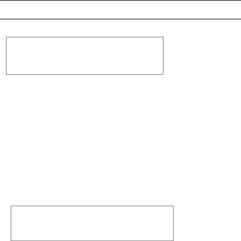
Controller Management
007-5510-002 31
NOTE :
The default administrator account name is “admin” and its password is “password.”
Similarly, the default user account name is “user” and its password is “password.”
Figure 3–2 Login Screen
3.1.3.2 Logout
To logout of the system, enter:
logout<Enter>
For a terminal session, you are returned to the general purpose user level.
For Telnet, the current session is disconnected.
3.1.3.3 Password
Entering the PASSWORD command allows the administrator to change the login names and passwords
for administrative and general purpose users (Figure 3–3). The associated privileges remain the same
regardless of the name or password changes.
Figure 3–3 Password Configuration Screen
Login names and passwords can be changed using the PASSWORD command, via RS-232 or Telnet
(see Section 3.1.3 in this guide). By default, the administrator name is “admin” and its password is
“password”. Similarly, the default user name is “user” and its password is “password.” If a user forgets
the password, entering PASSWORD DEFAULTS while logged in as “admin”, will restore all passwords
and user names to the default values.
3.1.3.4 Who Am I
To display the owner and the security level of the current terminal or Telnet session (Figure 3–4), enter:
whoami<Enter>
Enter a login name: admin
Enter the password: ********
15000 [1]: login
Successful CLI session login.
New owner : admin.
New security level: Administrative.
Enter new name to replace <admin>:
Enter old password: ********
15000 [1]: password
Enter new name to replace <user>:
Enter old password: ********
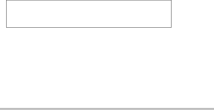
32 007-5510-002
Figure 3–4 WHOAMI Screen
3.2 Configuration Management
The controller provides uniform configuration management across heterogeneous SANs. Status of host
ports and storage assets are continuously being monitored.
Table 3–1 Controller Limits
3.2.1 Configure and Monitor Status of Host Ports
The status information of the host ports can be obtained at any time.
The HOST command displays the current settings and status for each host port (Figure 3–5 and
Figure 3–6). It also displays a list of the users currently logged into the system. An unauthorized user is
given the user name Anonymous.
CLI session:
Current owner : admin.
15000 [1]: whoami
Current security level: Administrative.
Item Limit
Number of LUNs 1024
Total Number of Users 512
Number of LUNs Per User 255
Number of LUNs per port (zoning) 255
FC logins per port 512
Number of IB Logins per HCA (2 ports) 256
Max RDMA size (IB only) 256 KB
Max Msg size (IB only ) 4 KB
Max Msg Depth (IB only ) 32
Max number of tiers per LUN 8
Max number of tiers 120
Max size of 32-bit LUN 0xFFFF0000 (blocks)
Max size of 64-bit LUN 168 TB
Granularity of LUN size 2 MB x number of tiers
Support LUN block sizes 512 bytes, 1K, 2K, 4K
Active host commands 32 per port
Max queued commands per host port (does not
include active host commands) 512
Max commands per disk 32 (can be lower for SATA
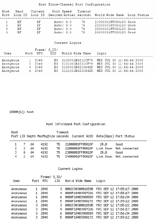
Controller Management
007-5510-002 33
The PORT=X|ALL parameter specifies the specific host port(s) (1 to 4) to be affected when used in
combination with any of the other parameters: ID, TIMEOUT, SPEED (for FC only), or WWN. The
default is to apply changes to ALL host ports.
Figure 3–5 FC Host Ports Configuration Screen
Figure 3–6 IB Host Ports Configuration Screen
3.2.1.1 Host ID
HOST ID=<new ID> changes the hard loop ID of a host port. The system selects a soft ID if the hard
loop ID is already taken by another device. This parameter is entered as an 8-bit hex value. The default
value is EF.
Host WWN
HOST WWN=X|DEFAULT overrides the system ID and specifies a different World Wide Name (WWN)
for a host port. This parameter is entered as an 64-bit hex value. Default WWN is based on the serial
number of the unit.
3.2.1.2 Host Status
HOST STATUS displays the loop status of each host port (Figure 3–7).
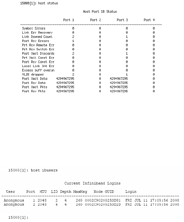
34 007-5510-002
HOST STATUSCLEAR resets the error counts.
Figure 3–7 IB Host Ports Status Screen
3.2.1.3 Host IB Users
HOST ibusers displays additional information on the Infiniband (IB) users logged into the controller.
(Figure 3–8).
Figure 3–8 Host IB Users Screen
3.2.1.4 Host Port Speed
HOST SPEED lets you display and change the port speed on the host port(s). You are prompted for the
desired speed as well as for the choice of host port(s).
3.2.2 Configure and Monitor Status of Storage Assets
Disk and Channel Information
The DISK command displays the current disk configuration and the status of the ten disk channels
(ABCDEFGHPS) on the controller (Figure 3–9).

Controller Management
007-5510-002 35
Figure 3–9 Disk Channel Screen
If the channel status is “acquiring loop synchronization,” this may indicate a channel problem. Refer to
4.2.2, "Recovering from Drive Failures" for recovery information.
Entering DISK INFO=<tier><channel> retrieves information about a specific disk (tier, channel).
DISK LIST displays a list of the disks installed in the system and indicates how many were found.
DISK SCAN checks each disk channel in the system for any new disks and verifies that the existing disks
are in the correct location. DISK SCAN also starts a rebuild operation on any failed disks which pass the
disk diagnostics.
DISK STATUS displays the loop status of each disk channel and a count of the SAS errors encountered
on each channel (Figure 3–10).
Figure 3–10 Disk Status Screen
DISK STATUSCLEAR=<tier><channel> resets the channel error counts.
DISK DEFECTLIST=<tier><channel> displays the defect list information for a specified disk. The tier
is in the range of <1..125>. The channel is one of the following: A, B, C, D, E, F, G, P, or S. The list is
classified into two types: G (Grown) and P (Permanent) (Figure 3–11).
The G list consists of the sectors that have become bad after the disk has left the factory and which can
be added to at any time. The P list consists of the bad sectors that are found by the disk manufacturer .
Disk Channel Status
LUN
--------------------------------------------------
InValDw:0
15000 [1]: disk status
A
0
B
0
C
0
D
0
E
0
F
0
G
0
H
0
P
0
S
0
InValDw:1 0000000000
InValDw:2 0000000000
InValDw:3 0000000000
LsDwSyn:0 0000000000
LsDwSyn:1 0000000000
LsDwSyn:2 0000000000
LsDwSyn:3 0000000000
PhyRst:0 0000000000
PhyRst:1 0000000000
PhyRst:2 0000000000
PhyRst:3 0000000000
RunDisp:0 0000000000
0 RunDisp:1
RunDisp:2
RunDisp:3
0
Recovery
0
0
0
0
0
0
0
0
0
0
0
0
0
0
0
0
0
0
0
0
0
0
0
0
0
0
0
0
0
0
0
0
0
0
0
0
0
0
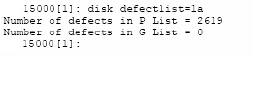
36 007-5510-002
Figure 3–11 Disk Defect List Screen
DISK FAIL=<tier><channel> instructs the system to fail the specified disk at the physical tier in the
range of <1 ...125> and channel in the range of <ABCDEFGHPS>. When a non-SPARE disk is specified
and it is failing, the disk will not cause a multi-channel failure. The disk is marked as failed. An attempt
is made to replace it with a spare disk. When a SPARE disk is specified and it is currently in use as a
replacement for a failed disk, the disk that the spare is replacing is put back to a failed status and the spare
is released, but marked as unhealthy and unavailable.
DISK PLS=<tier><channel> requests/displays the PHY Link Error Status Block information for the
specified drive.
The disk is specified by its physical tier and channel locations, 'tc', where:
• 't' indicates the tier in the range <1..120>, and
• 'c' indicates the channel in the range <ABCDEFGHPS>.
If neither the tier nor the channel are specified, the PLS information is requested from all drives. If only
the tier is specified, the PLS information is requested from all the drives on the specified tier.
Table 3–2 on page 37 shows the types of PHY errors. Note that SATA and SAS drives report PHY errors
differently.

Controller Management
007-5510-002 37
Table 3–2 PHY Link Error Status Block Information
NOTE :
SATA drives have an Active/Active MUX (AAMUX) installed. Error counts are read
directly from the AAMUX.
SATA AAMUX PHY ERRORS
H-RX The number of SATA FIS CRC errors received on the host port of the AAMUX
H-TX The number of SATA R_ERR primitives received on the host port indicating a problem
with the transmitter of the AAMUX
H-Link The number of times the PHY has lost link on the host port.
H-Disp The number of frame errors for the host port of the AAMUX. These include: code error,
disparity error, or realignment
O-RX The number of SATA FIS CRC errors received on the other host port of the AAMUX
O-TX The number of SATA R_ERR primitives received on the other host port indicating a
problem with the transmitter of the AAMUX
O-Link The number of times the PHY has lost link on the other host port.
O-Disp The number of frame errors for the other host port of the AAMUX. These include: code
error, disparity error, or realignment.
D-RX The number of SATA FIS CRC errors received on the device port of the AAMUX
D-TX The number of SATA R_ERR primitives received on the device port indicating a problem
with the transmitter of the AAMUX.
D-Link The number of times the PHY has lost link on the device port.
D-Disp The number of frame errors for the device port of the AAMUX. These include: code error,
disparity error, or realignment.
SAS PHY ERRORS
InvDW Invalid DWORD Count - The number of invalid dwords received outside of the PHY
reset sequence.
RunDis Running disparity Count - The number of dwords containing running disparity errors
received outside of the PHY reset sequence
LDWSYN Loss of DWORD synchronization count - The number of times the PHY has lost
synchronization and restarted the link reset sequence
PHYRES PHY Reset Problem count - The number of times the PHY reset sequence has failed.

38 007-5510-002
Figure 3–12 Disk PLS Tier 1 Status Screen
For other DISK parameters, see section 3.2.10 "Automatic Drive Rebuild" in this guide.
3.2.2.1 Tier View
Tiers (also known as RAID groups) are the basic building blocks of the controller. In an 8+1 mode, a
tier contains 10 drives: eight (8) data drives (Channels A through H), one(1) parity drive (Channel P),
and an optional spare drive (Channel S). In an 8+2 mode, a tier contains 10 drives, but the setup is
different: eight (8) data drives (Channels A through H), and two (2) parity drives (Channel P and S).
Drives that have the same SAS ID across all ten channels are put on the same tier. Tiers are automatically
added to the system when the disks are detected. A tier will automatically be removed if it is not in use
by any of the LUNs and all of the disks in the tier are removed or moved to another location.
Entering TIER lets you display the current status and configuration of the tiers in the system.
The tiers’ total and available capacities are shown under the “Capacity” and “Space Available” columns
respectively.
The TIER command shows the status of each disk on the tier as follows:
• A letter <ABCDEFGHPS> represents a healthy disk at that location.
• A space indicates that the disk is not present or detected.
• A period (.) denotes that the disk was failed by the system.
• The symbol “?” indicates that the disk has failed the diagnostic tests or is not configured correctly.
• The character “r” indicates that the disk was failed by the system and replaced by a spare disk.
• The symbol “!” indicates that the disk is in the wrong location.
NOTE :
The rate of rebuild and format operations can be adjusted with the commands, Tier
Delay=x and Tier Extent=x.
Channel
--------------------------------------------------
H-RX:
15000 [1]: disk pls
A
.
B
.
C
.
D
.
E
.
F
.
G
.
H
.
P
.
S
.
H-TX: ..........
H-Link: ..........
H-Disp: ..........
O-RX: ..........
0-TX: ..........
O-Link: ..........
0-Disp: ..........
D-RX: ..........
D-TX: ..........
D-Link: ..........
D-Disp: ..........
InvDW: 0000000000
0 RunDis:
LDWSYN:
PHYRES:
0
0
0
0
0
0
0
0
0
0
0
0
0
0
0
0
0
0
0
0
0
0
0
0
0
0
0
0
0
PHY Error Status Blocks
Tier 1
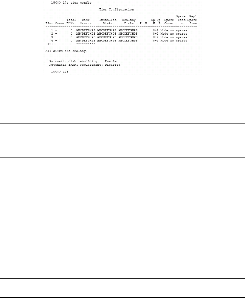
Controller Management
007-5510-002 39
3.2.2.2 Tier Configuration
TIER CONFIG displays the detailed tier configuration information for all of the tiers (Figure 3–13).
Figure 3–13 Tier Configuration Screen
The headings for the Tier Configuration screen indicate the following values or conditions for the tiers.
Total LUNs lists the number of LUNs that currently reside on the tier.
NOTE :
The health indication for the spare channel under the 'Healthy Disks' heading is an
indication of the health of the spare disk (if any) that is currently being used to replace
a disk on the listed tier. The health indication for the spare channel that is physically
on the listed tier is found under the 'Sp H' heading.
These headings indicate the respective conditions on the tier.
Ffailed disk (if any).
Rreplaced disk (if any).
Sp H whether the spare disk that is physically on the tier is healthy.
Sp A whether the spare disk that is physically on the tier is available for use as a
replacement.
Spare Owner current owner of the physical spare tier, where ownership is assigned when the
spare is used as a replacement.
Spare Used on tier (if any) on which this physical spare is being used as a replacement.
Repl Spare from tier (if any) whose spare disk is being used as a replacement. Tiers are in 8+1
mode by default.
NOTE :
RES-# will display under the Spare Owner heading while a replacement operation is
underway to indicate that unit '#' currently has the spare reserved.
TIER CONFIG=ALL displays tier configuration and replacements for both 8+1 and 8+2 modes. (Figure
3–14).
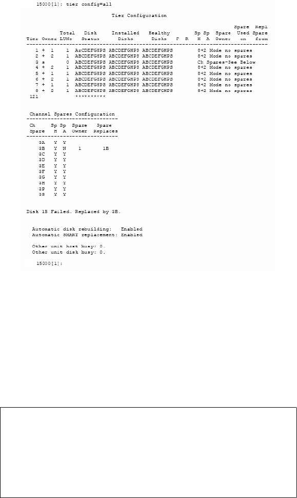
40 007-5510-002
Figure 3–14 Tier Configuration ALL Screen
3.2.2.3 LUN View
Entering the LUN command displays the current status of the LUNs (
). “Ready” indicates that the LUN is in good condition. The percentage of completion is displayed if the
LUN is being formatted or rebuilt. A status of “Unavailable” may result from multiple drive failures.
“Ready [GHS]” indicates that a spare drive has been successfully swapped for one of the drives the tier.
Figure 3–15 LUN Status Screen
LUN LIST displays a list of all valid LUNs in the system. The list shows the capacity, owner, status, and
serial number of each LUN (Figure 3–16).
Logical Unit Status
Block
Size
LUN Owner Tier ListCapacity
(Mbytes)
512
-------------------------------------------------------------------------
10002Ready [GHS]0
System Capacity 2240096 Mbytes, 2200088 Mbytes available.
15000 [1]: lun
Status
11
51210002Ready11 2
51210002Ready21 3
51210002Format 14%31 4
Tiers
1
1
1
1
Label
vol1
vol2
vol3
vol4

Controller Management
007-5510-002 41
Figure 3–16 LUN List Screen
3.2.2.4 LUN Configuration
LUN CONFIG displays the configuration information for all the valid LUNs in the system (Figure 3–17).
Figure 3–17 LUN Configuration Screen
3.2.2.5 LUN Reservations
LUN RESERVATIONS displays a list of all valid LUNs in the system and shows which LUNs currently
have a SCSI reservation and which initiator holds the reservation (Figure 3–18).
LUN RELEASE releases any SCSI reservations and registrations on a LUN.
Figure 3–18 LUN Reservations Screen
3.2.2.6 Adding/Removing Storage Assets
The controller supports up to 120 tiers. New tiers can be added without affecting system operations.
DISK SCAN checks each disk channel in the system for any new disks. New tiers are automatically
added to the system when the disks are detected. A tier is automatically deleted if it is not in use by any
of the LUNs and all of the disks in the tier are removed or moved to another location.
Logical Unit Status
Serial
Number
LUN Owner Capacity
(Mbytes)
00015A1300A7
-------------------------------------------------------------------------
10002Ready [GHS]0
System Capacity 2240096 Mbytes, 2200088 Mbytes available.
15000 [1]: lun list
Status
1
0001A28101A710002Ready11
0001A29A03A710002Ready21
Label
vol1
vol2
vol3
0001A2b1040010002Ready31vol4
Logical Unit Configuration
Tier
End
LUN Block Tier
Start
1FFFFF
-------------------------------------------------------------------------
0 00
15000 [1]: lun config
LUN
512
Capacity
1000000
(Blocks) Size Offset
Tier List
1 2
2FFFFF200000 01 5122000000 1 2 3 4
27FFFF200000 01.00 5121000000
2FFFFF28000010000001.01 5121000000
Current SCSI LUN Reservations
PortLUN Status
-------------------------------------------------------------------------
No SCSI Reservations0
15000 [1]: lun reservations
Reservation ID
Ready
Label User Name
No SCSI Reservations1 Ready
No SCSI Reservations2 Ready

42 007-5510-002
3.2.2.7 Status of Drive Enclosures
The SES command displays the failures reported by the enclosure (Figure 3–19), through the SCSI
Enclosure Services (SES). It also provides a means to access SES specific functions such as disk,
channel, and LUN. Drive failures are not displayed using the SES command; you must use the TIER
command to view drive status.
Figure 3–19 Displaying the Current Disk Enclosure Failures
If your enclosures provide redundant SES communication paths, the error is reported twice. In Figure
3–19, EncID is the Enclosure Logical Indentifier of the enclosure that reported the failure. The last
four digits of the WWN are the last four digits of the enclosure’s serial number.
SES ON saves the SES state to the parameter blocks, and starts up the SES monitors.
SES OFF saves the SES state to the parameter blocks, and shuts down the SES monitors.
3.2.2.8 Display SES Devices Information
SES SHOWDEVICES displays all the SES devices on all channels.
SES SHOWALL displays all configuration information for all the SES devices on all channels.
SES SHOW=<tier><channel> displays the configuration information and the status information
returned from an SES Enclosure Status page for the SES device for the specified drive in the range of
<1..120> and <ABCDEFGHPS>.
3.2.2.9 Visual Indication of Drive
SES IDDISK=<tier><channel> provides a visual indication of the specified drive
(<1..120><ABCDEFGHPS>). The status LED of the drive blinks until the command SES ID=OFF is
issued. The SES ID=OFF command restores the system to its original visual state.
3.2.2.10 Visual Indication of Tier
SES IDTIER=<tier> provides a visual indication of the specified tier <1..125>. The status LED of the
drives blinks until the command SES ID=OFF is issued, which restores the system to its original visual
state.
3.2.2.11 Visual Indication of Channel
SES IDCHANNEL=<channel> provides a visual indication of the specified channel
<ABCDEFGHPS>. The status LED of the drives blinks until the command SES ID=OFF is issued,
which restores the system to its original visual state.
3.2.3 Tier Mapping for Enclosures
The controller supports various drive enclosures. When the system is first configured, it is necessary to
select a tier mapping mode so that the position of the tiers in the system are changed to conform with the
layout of your drive enclosures. The tier mapping information also allows the controller to properly light
the enclosure fault LEDs.
EncID:50050CC0000033C8: Power Supply 1:DC Power Failure
15000 [1]: ses

Controller Management
007-5510-002 43
TIER MAP displays the current mapping mode for the disks in the array.
TIER CHANGEMAP changes the current tier mapping for the disks in the array. To change the current
tier mapping, do the following:
1. Enter: tier changemap<Enter>
2. Select the appropriate mapping mode for your drive enclosures and press <Enter>.
3. For the changes to take effect, enter: restart<Enter>.
NOTE :
The CHANGEMAP command should only be used when the system is first configured.
Changing the mapping mode will alter all the tier information, making LUN information
inaccessible.
3.2.4 System Network Configuration
These commands do the following:
NETWORK displays the current network interface settings.
NETWORK USAGE displays the address resolution protocol map, ICMP (ping), general network, and
IP, TCP, and UDP layer statistics.
NETWORK IP=<new address> changes the IP address. (The system must be restarted before the
changes will take effect).
NETWORK NETMASK=<aaa.bbb.ccc.ddd> changes the netmask.
NETWORK GATEWAY=<aaa.bbb.ccc.ddd> sets the current gateway in the network routing table to
the supplied Internet address. The gateway is where IP datagrams are routed when there is no specific
routing table entry available for the destination IP network or host.
NOTE :
GATEWAY=<no Internet address> clears out the current gateway.
NETWORK PRIVATE displays the MAC address for the private network device.
3.2.4.1 Telnet
NETWORK TELNET=ON|OFF enables/disables the Telnet capability on the controller. The system
must be restarted before the changes will take effect.
NOTE :
To only temporarily affect Telnet session availability during a concurrent power-cycle,
refer to the TELNET command in Section 3.6 "Remote Login Management" in this
guide.
NOTE :
Telnet connections are “clear text.” If Telnet connections are used, you may expose
controller passwords to third parties. For greater security, turn off Telnet access if it is
not required.

44 007-5510-002
NETWORK TELNETPORT=<port number> changes the Telnet port number for the current controller.
The system must be restarted before the changes will take effect. Valid port numbers are 0 to 32768;
however, the results may be unpredictable if the port number chosen is already in use (on this unit) by
either the GUI or SYSLOG facilities. The default port number is 23.
3.2.4.2 SNMP & Syslog
NETWORK SNMP=ON|OFF enables and disables the SNMP functionality. The system must be
restarted before the changes will take effect.
NETWORK LIMIT_SNMP=ON|OFF specifies whether the SNMP functionality will only report
component-level information, or all levels of information, The default setting is OFF.
NETWORK TRAPIP=<aaa.bbb.ccc.ddd> changes the destination IP address for SNMP trap packets.
The system must be restarted before the changes will take effect.
NETWORK SYSLOG=ON|OFF enables and disables the Syslog capability.
NOTE :
NETWORK SYSLOG should be enabled , since it is the best way to find out what
occurred in the event of a problem. However, since some problems can produce a large
amount of output, it is a good idea to have your syslog program configured to rotate
based on log size rather than date.
NETWORK SYSLOGIP=<aaa.bbb.ccc.ddd> changes the destination IP address for syslog packets,
Both controllers in the couplet pair will share the same syslog destination IP address but each controller
can specify a different destination port.
NETWORK SYSLOGPORT=<port number> changes the destination port number for syslog packets
for the current controller. Both controllers in the couplet pair will share the same syslog destination IP
address but each controller can specify a different destination port. Valid ports are 0 to 32768. However
the results may be unpredictable if the port number chosen is already in use (on this unit) by the TELNET
facilities. Default port number is 514.
NOTE :
The controller sends syslog messages via the local 7 (23) facility.
Refer to Chapter 4,"Controller Remote Management and Troubleshooting" in this guide for information
on how to set up Telnet and SNMP functionality on your host computer.
3.2.4.3 API Server Connections
NETWORK API_SERVER=ON|OFF enables/disables the API server capability. The system must be
restarted before the changes will take effect.
NOTE :
To affect the API Server connection availability only temporarily during the current
power-cycle, see Section 3.8.2, "API Server Connections".
NETWORK API_PORT=<port number> specifies the API Server port number for the current
controller. The system must be restarted before the changes will take effect. Valid ports are 0 to 32768.
The results may be unpredictable if the port number chosen is already in use (on this unit) by either the
TELNET or SYSLOG facilities. The default port number is 8008.

Controller Management
007-5510-002 45
3.2.4.4 Displaying and Editing the Routing Table
The ROUTE command displays the current routing table of the system (Figure 3–20) and allows the
administrator to change it. The routing table describes how the controller can communicate with the
hosts on other networks.
Figure 3–20 Routing Table
ROUTE ADD=<aaa.bbb.ccc.ddd> GATEWAY=<aaa.bbb.ccc.ddd> adds gateways to the routing
table. Up to 6 permanent routes can be added to the tables. For example, to indicate that the machine with
Internet address 91.0.0.3 is the gateway to the destination network 90.0.0.0, enter: ROUTE
ADD=90.0.0.0 GATEWAY=91.0.0.3
ROUTE DEL=<aaa.bbb.ccc.ddd> GATEWAY=<aaa.bbb.ccc.ddd> deletes gateways from the routing
table.
ROUTE GATEWAY=<aaa.bbb.ccc.ddd> sets the current gateway in the network routing table to the
specified Internet address. The gateway is where IP datagrams are routed when there is no specific
routing table entry available for the destination IP network or host. If an empty gateway value is
provided, then the current gateway is cleared.
3.2.5 Restarting the Controller
3.2.5.1 System Restart
RESTART performs a restart on the controller on which the command is issued. This command prepares
the system to be restarted. The system halts all I/O requests and saves the data to the disks before
restarting. The restart process may take several minutes to complete.
NOTE :
If cache coherency is enabled, restarting a controller unit will cause the partner
controller to fail the restarting unit. Once the reboot is complete, you will have to heal
the controller unit.
RESTART DELAY=X (where “X” is minutes) delays a restart of a unit between 0 and 255 minutes.
destination
Gateway 172.16.0.254
Permanent Routing Table:
15000 [1]: route
gateway
----------------------------
0.0.0.0 172.16.0.254
----------------------------
ROUTE NET TABLE
destination gateway
--------------------------------------------------------------------
0.0.0.0 172.16.0.254
--------------------------------------------------------------------
Current Routing Tables:
flags
3
Refcnt
0
Use
46569
Interface
fei0
172.16.0.0 172.16.0.1 101 03 fei0
192.168.0.0 172.13.0.254 3 01 fei0
ROUTE HOST TABLE
-------------------------------------------------------------------
-------------------------------------------------------------------
destination gateway flags Refcnt Use Interface
127.0.0.1 127.0.0.1 5 12 l00
========================
=========================

46 007-5510-002
RESTART DUAL restarts both units.
RESTART KILL stops a timed restart that is in progress.
3.2.5.2 System Shutdown
SHUTDOWN shuts down the controller unit.
If you need to power down the controller, use SHUTDOWN prior to shutting off power. This will cause
the controller to flush its cache, abort all format and rebuild operations, and proceed with an orderly
shutdown.
All hosts actively using the controller should be safely shutdown and all users logged out before using
this command. The controller will halt all I/O requests and save the data to the disks.
NOTE :
Use SHUTDOWN whenever you power down the controller for maintenance.
SHUTDOWN flushes any data left in the cache and prepares the controller for an orderly
shutdown. For couplet controller configuration, issue SHUTDOWN to both controllers.
To perform a hard restart of the unit by cycling the power, use: SHUTDOWN RESTART=X, where X is
a value between 1 and 1023 seconds before the unit powers up again. If the number is not specified, the
default is 15 seconds.
NOTE :
If SHUTDOWN RESTART is used in conjunction with the DUAL parameter, the
restart will only affect unit where it was issued on and not both.
SHUTDOWN DELAY=X delays a shutdown of a unit between 0 and 255 minutes (where x is minutes
delayed).
SHUTDOWN DUAL shutdowns both units.
SHUTDOWN KILL stops a timed shutdown that is in progress.
3.2.6 Setting the System’s Date and Time
Valid date settings are between years 2000 and 2104. In dual mode, settings should always be done on
Unit 1. Changes will automatically be applied to both units. Settings are automatically adjusted for leap
years.
3.2.6.1 System Date
DATE displays the current system date.
You can also change the system date. At the prompt, type:
date mm dd yyyy <Enter>
where mm represents the two digit value for month, dd represents the two digit value for day, and yyyy
represents the four digit value for year.
For example, to change the date to March 14, 2009, type:
date 03 14 2009<Enter>.
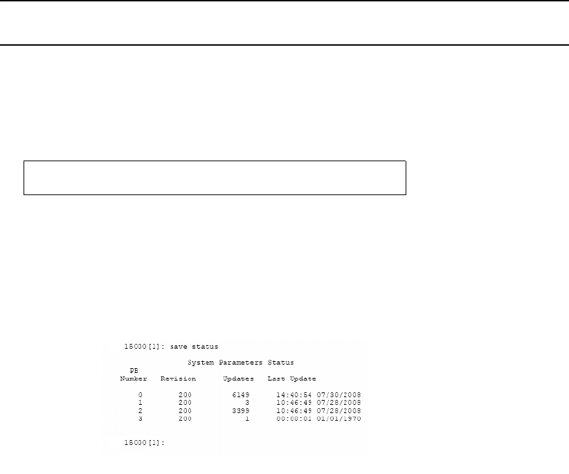
Controller Management
007-5510-002 47
3.2.6.2 System Time
TIME displays the current system time.
You can also change the system time. At the prompt, type:
time hh:mm:ss<Enter>
where hh represents the two digit value for hour (00 to 24), mm represents the two digit value for
minutes, and ss represents the two digit value for seconds.
For example, to change the system time to 2:15:32 p.m., type:
time 14:15:32<Enter>
NOTE :
The system records time using the military method, which records hours from 00 to 24,
not in a.m. and p.m. increments of 1 to 12.
3.2.7 Saving the Controller’s Configuration
The SAVE command can be used to save the system configuration to non-volatile memory
(Figure 3–21).
Figure 3–21 Saving System Parameters Screen
Backup copies of the system configuration are also saved on the disks. The system will automatically
save and update the backup copies when changes are made to the system configuration or status.
The SAVE STATUS command, in addition to saving the parameter blocks to non-volatile memory and
on the disks, displays the current status of the system parameters (Figure 3–22).
Figure 3–22 Current System Parameters Status Screen
Normally, the system must determine which copy of the parameter blocks is more recent, the one on the
disks or the internal copy. When the system reboots, it will load the more recent copy.
3.2.8 Restoring the System’s Default Configuration
The DEFAULTS command may be used to restore the system to its default configuration.
Saving system parameters. Done.
15000 [1]: save
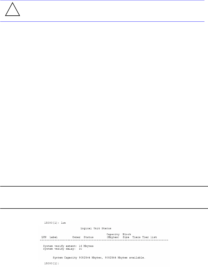
48 007-5510-002
The system will halt all I/O requests, delete all the LUNs and restore all the parameters back to their
default values. This is a destructive operation which will delete all the data stored in the system.
The system will ask if you want to erase all the configuration information stored on the disks. This will
prevent the system from retrieving the backup copies of the configuration settings from the disks after
the system is restarted. After the default settings have been loaded, the system will ask if you want to
begin reconfiguration by scanning for the disks. New LUNs can be created after the disks have been
added back to the system.
3.2.9 LUN Management
The controller creates centrally-managed and vendor-independent storage pooling. It enables different
types of storage to be aggregated into a single logical storage resource from which virtual volumes
(LUNs) can be served up to multi-vendor host computers. The networked storage pools will provide the
framework to manage the growth in storage demand from web-based applications, database growth,
network data-intensive applications, and disaster tolerance capabilities.
3.2.9.1 Configuring the Storage Array
The storage array may consist of up to 120 tiers, depending on individual disk enclosure’s numbering
scheme. The tiers can be combined, used individually, or split into multiple LUNs. A LUN can be as
small as part of a tier or as big as the whole system. LUNs can be shared or dedicated to individual users.
Up to 1024 LUNs are supported in total. LUNs are “owned” by the controller via which they are created.
You can add and remove LUNs without affecting system operations. Use the LUN command to display
the current Logical Unit Status (Figure 3–23).
NOTE :
In dual mode, LUNs will be “owned” by the controller unit on which they are created.
Hosts will only see the LUNs on the controller to which they are connected, unless cache
coherency is used.
Figure 3–23 Logical Unit Status Screen
3.2.9.2 Creating a LUN
LUNs can be added to the system based on two commands.
The DEFAULT command will delete all LUN configuration and data
unconditionally. Do not issue this command without guidance from SGI.
!
Warning
Controller Management
007-5510-002 49
To add a 32-bit LUN that will not exceed 2 TB, type:
lun add=X<Enter>
To add a 64-bit LUN, that exceeds 2 TB:
lun add64=X<Enter>
For both cases, “X” is the Logical Unit with a range of <0..1023>.
For either case, the system prompts you for all the necessary information to create the LUN and indicates
if the LUN was successfully added to the system.
The required LUN information includes:
•Capacity (in MBytes) - default is to use all available capacity
•Number of tiers - default is to use all tiers
•Block size (in Bytes) - default is 512Bytes
•Label - may contain up to 12 characters
3.2.9.3 Formatting a LUN
A LUN must be formatted before it can be used.
To format a LUN, use LUN FORMAT. Specify the LUN <0..1023> when prompted. This performs a
destructive initialization on the specified LUN by over-writing all the data on the LUN with zeroes.
The rate of format can be adjusted using the DELAY and EXTENT parameters of the LUN command.
3.2.9.4 Interrupting a LUN Format Operation
If you need to interrupt a format operation, for any reason, use these commands:
•LUN PAUSE pauses the current format operations.
•LUN RESUME releases the paused format operations.
•LUN STOP aborts all the current format operations.
3.2.9.5 Changing a LUN Label
To change the label of a LUN:
1. Type:
lun label <Enter>.
2. Select the LUN to change <0..1023> and press Enter.
3. Type in the new label and press Enter. A LUN label may contain up to 12 characters (Figure 3–24).

50 007-5510-002
Figure 3–24 Changing a LUN Label Screen
3.2.9.6 Moving a LUN (Dual Mode Only)
To change the ownership of a LUN from one controller to its partner (when the units are in dual mode),
enter:
lun move=x <Enter>
where x is the Logical Unit number <0..1023> (Figure 3–25). If a LUN is on a tier that is shared by other
LUNs, the controller will prompt and then move the other dependent LUNs as well.
Figure 3–25 Moving a LUN
3.2.9.7 Deleting a LUN
LUN DEL=x (where “x” is the LUN <0.1023>) deletes a LUN from the system. You can only delete a
LUN that is owned by the controller unit onto which you are logged.
SCSI Reservations
LUN RELEASE=x allows you to release all SCSI reservations on a LUN. The command LUN
RESERVATIONS can be used to view the current SCSI reservations on all of the LUNs in the system.
The LUN to be released can be specified by “x” where “x” is in the range <0..1023>.
LUN START lets you start all the LUNs that have been stopped by a SCSI START/STOP request. This
parameter is not related to the LUN STOP command.
3.2.10 Automatic Drive Rebuild
The controller’s automatic drive failure recovery procedures ensure that absolute data integrity is
maintained while operating in degraded mode. In the event of a drive failure, the controller will
automatically initiate a drive rebuild using a spare drive if the “autorebuild” function has been enabled.
Enter the LUN to label (0..1023), ‘e’ to exit:
15000 [1]: lun label
0
Enter a new label for LUN 0, up to 12 characters:
vol1
Logical Unit Status
Block
Size
LUN Owner Tier ListCapacity
(Mbytes)
512
-------------------------------------------------------------------------
10002Ready [GHS]0
System Capacity 277810 Mbytes, 237802 Mbytes available.
Status
11
51210002Ready12 2
51210002Ready21 3
51210002Ready32 4
Tiers
1
1
1
1
Label
vol1
15000 [1]: lun move=0
LUN 0 is owned by this 15000.
Do you want to move ownership to the OTHER 15000? (y/n):

Controller Management
007-5510-002 51
Use the TIER command to display the current setting (Figure 3–26). The rebuild operation can take up
to several hours to complete, depending on the size of the disk and rate of rebuild.
Figure 3–26 Automatic Disk Rebuilding Parameter
TIER AUTOREBUILD=ON|OFF enables/disables the automatic disk rebuild function. A disk will only
be replaced by a spare disk if it fails and Autorebuild is ON (ON being the default setting). This function
should always be enabled so that data can be reconstructed on the spare drive when a drive failure occurs.
After the failed drive is replaced, data will be automatically copied from the spare drive to the
replacement drive.
3.2.10.1 Manual Drive Rebuild
DISK REBUILD=<tier><channel> initiates a rebuild on a specific drive. This operation will reconstruct
data on the replacement drive and restore a degraded LUN to healthy status.
3.2.10.2 Drive Rebuild Verify
DISK REBUILDVERIFY=ON|OFF determines if the system will send SCSI Write with Verify
commands to the disks when rebuilding failed disks. This feature is used to guarantee that the data on the
disks is rebuilt correctly. Default is OFF. This feature will increase the time it takes for rebuilds to
complete.
3.2.10.3 Manual Drive Replace
To replace the specified failed drive with a spare drive, enter: DISK REPLACE=<tier><channel>
A Replace operation is used to temporarily replace a failed disk with a healthy spare disk.
3.2.10.4 Interrupting a Rebuild Operation
To interrupt a Rebuild operation, use these commands:
•TIER PAUSE pauses the current rebuild operations.
•TIER RESUME releases the paused rebuild operations.
•TIER STOP aborts all the current rebuild operations.
3.2.11 SMART Command
Use the SMART command to identify failing drives before they fail.
Tier Status
Space Available
(Mbytes)Owner Disk Status Lun List
Capacity
(Mbytes)
ABCDEFGHPS
-------------------------------------------------------------------
280012280012
ABCDEFGHPS280012280012
ABCDEFGHPS280012280012
Automatic disk rebuilding is Enabled
15000 [1]: tier
System rebuild extent: 32 Mbytes
System Capacity 840036 Mbytes, 840036 Mbytes available.
System rebuild delay: 60
Tier
1
2
3
52 007-5510-002
SMART ENABLE enables SMART on all the disk drives installed in the system and updates the
parameter blocks on the disk. This enables the Information Exception and the Temperature warnings.
However, the user can skip the update part and enter SMART DISKUPDATE later to write the
parameter blocks to the disks.
SMART DISABLE disables SMART on all the disk drives installed in the system and updates the
parameter blocks on the disk. However, the user can skip the update part and call and enter SMART
DISKUPDATE later to write the parameter blocks to the disks.
SMART STATUS displays the SMART ENABLE status of a specified disk. The disk is specified by its
physical tier and channel locations, 'tc', where:
• 't' indicates the tier in the range <1..125>
• 'c' indicates the channel in the range <ABCDEFGHPS>.
Displays the Information Exception and the Temperature warnings if enabled for a specified disk; (i.e.
SMART ENABLE).
SMART UPDATE updates the parameter blocks that correspond to the SMART configuration.
SMART DATA=tc displays the SELF TEST log. Also reads and displays the SMART information of the
specified disk. The disk is specified by its physical tier and channel locations, 'tc', where:
• 't' indicates the tier in the range <1..125>
• 'c' indicates the channel in the range <ABCDEFGHPS>.
SMART SELFTEST=tc|testtype starts a specified self test on a specified hard disk. The disk is specified
by its physical tier and channel locations, 'tc', where:
• 't' indicates the tier in the range <1..125>
• 'c' indicates the channel in the range <ABCDEFGHPS>.
There are 3 tests to choose from: default test, Background short test, and Background long test. All the
tests are supported on the SAS drives, while only the Background short test is supported on the SATA
drives.
SMART ABORTSELFTEST=tc aborts a self test that has been launched using the SMART SELFTEST
command. The abort event will logged to the self test log.
The disk is specified by its physical tier and channel locations, 'tc', where:
• 't' indicates the tier in the range <1..125>
• 'c' indicates the channel in the range <ABCDEFGHPS>.
SMART ABORTSELFTEST=ALL. This command only works for SAS disks. Aborts background self
tests on all disks.
SMART CLEAR=tc|all Clears SMART trips on specified drives or all drives.
• 't' indicates the tier in the range <1..125>
• 'c' indicates the channel in the range <ABCDEFGHPS >
• ‘ALL’ indicates all drives.
SMART LOG=tc|ALL reads the self test log from the specified disk and displays it.
• 't' indicates the tier in the range <1..125>
• 'c' indicates the channel in the range <ABCDEFGHPS>.
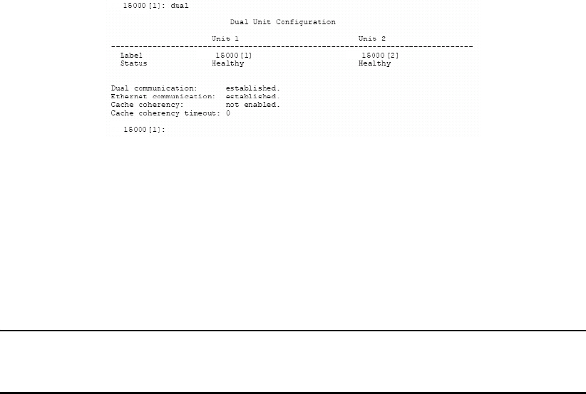
Controller Management
007-5510-002 53
SMART TEST=ON enables the test bit in the Information exception mode page for all the disks installed.
Setting the test bit simulates a FALSE SMART trip condition which raises a FALSE check condition to
the controller. Currently, this parameter is valid only with Fibre Channel disks.
SMART TEST=OFF disables the test bit in the Information exception mode page for all the disks
installed.
SMART INTERVALTIME displays the interval (in hours) in which the SMART Information will be
polled.
SMART INTERVALTIME=h sets the interval (in hours) that SMART Information polling will occur. 'h'
indicates the interval in hours in the range <1..24>.
3.2.12 Couplet Controller Configuration (Cache/Non-Cache Coherent)
There are two primary couplet controller configurations: cache coherent and non-cache coherent.
The DUAL command displays information about couplet system configuration (Figure 3–27).
Figure 3–27 Couplet Controller Configuration
3.2.12.1 Cache Coherent
In this configuration, each controller can access all LUNs. The couplet controller communication occurs
over the internal UART and private Ethernet. If the controllers detect an Ethernet failure, controller 2
will be failed. (This means that an external event can cause a controller to fail even though the controller
may be perfectly fine.) Therefore, it is mandatory that the controller Ethernet resides on a private
Ethernet segment.
NOTE :
Data cache is not copied from one controller to another. If a controller fails, all “dirty”
data in cache will be lost. Thus if power failures are a concern, writeback cache should
be disabled.
Non-Cache Coherent
In this configuration, the couplet controller communication occurs over the internal UART. Each
controller owns LUNs and tiers. Spare drives are “owned” by individual controller units, according to
tier ownership.
In healthy situations, the controller cannot access LUNs or tiers owned by the other controller. However,
if the other controller is failed, the healthy controller will have access to all LUNs and tiers.
Users, via mapping, can be assigned any combination of LUNs. In a healthy environment, users will only
see LUNs owned by the controller to which they are connected.

54 007-5510-002
For example, a user is given access to internal LUNs 5, 6, and 7, which are mapped to external LUNs 0,
1, and 2, respectively. controller 1 owns LUNs 0 and 1 while controller 2 owns LUN 2. The user is
physically connected to controller 1, thus, they will only see LUNs 0 and 1. The user will not be able to
access LUN 2. If the user was physically connected to controller Unit 2, the reverse would be true: only
LUN 2 would be accessible. When a controller fails, the user will be given access to all mapped LUNs
regardless of the physical connection.
Data cache is not copied from one controller to another. If a controller fails, all “dirty” data in cache will
be lost. Thus if power failures are a concern, writeback cache should be disabled.
DUAL COHERENCY=ON|OFF enables/disables the cache coherency function. Default is dual
coherency disabled which is the non-cache coherent configuration.
DUAL TIMEOUT=X allows you to set the cache coherency timeout for cache node requests in seconds.
Valid range is <0...255>. Default is zero (0) seconds. The timeout value should be less than the host
timeout value (HOST TIMEOUT=X). A timeout value of 0 allows for only one retry.
NOTE :
In dual mode, LUNs will be “owned” by the controller unit on which they are created.
Hosts will only see the LUNs on the controller to which they are connected, unless cache
coherency is enabled.
3.2.12.2 Fail / Restore the Other Controller Unit in the Couplet Pair
To fail the other controller unit in the system (for example, in order to perform maintenance), enter:
dual fail <Enter>
The healthy controller unit will take ownership of all the LUNs/tiers from the failed controller unit.
To restore the other controller unit in the system to healthy status after failure recovery, enter:
dual heal <Enter>
Ownership of LUNs/tiers are transferred back to the formerly failed controller unit.
3.2.12.3 Labeling the Controller Unit(s)
You may change the label assigned to each controller unit. This allows you to uniquely identify each unit
in the controller system. The CLI prompt for each controller is built by adding a colon (:) and a space at
the end of the label. Each controller can have a label up to 31 characters long.
To change the label:
1. Type: dual label=1|2 <Enter>.
2. Select which unit you want to rename (Figure 3–28).
3. When prompted, type in the new label for the selected unit. The new name is displayed.
NOTE :
If you type DEFAULT for the new label, the label for the unit is restored to its default
setting.

Controller Management
007-5510-002 55
Figure 3–28 Labeling a Controller Unit
3.2.12.4 Singlet
The DUAL SINGLET command sets the system in the singlet mode. System recognizes only Unit 1. This
command:
• disables cache coherency
• heals unit 1 if it is failed
• fails unit 2 before attempting to remove it.
To set the system in singlet mode not couplet mode, type: dual singlet<Enter>.
NOTE :
The system may automatically add unit 2 if it is connected to the system. Therefore, we
advise you to power off and remove unit 2 from the system after the Dual Singlet
command is completed.
3.3 Performance Management
The controller optimizes performance operations due to its extensive monitoring and reporting
capability.
3.3.1 Optimizing I/O Request Patterns
The controller manages pre-fetch and cache efficiency through the LUN.
Display Current Cache Settings
The CACHE command displays the current cache settings for each LUN in the system( Figure 3–29).
Enter the number of the unit you wish to rename.
15000 [1]: dual label
LABEL=1 for unit 1, Test System[1]
LABEL=2 for unit 2, Test System[2]
unit: 1
Enter a new label for unit 1, or DEFAULT to return to the default label.
Up to 31 characters are permitted.
Current unit name: Test System[1]
New unit name: System[1]

56 007-5510-002
Figure 3–29 Cache Setting Screen
You can use the LUN=x option to specify which LUN to change. If no LUN is specified, changes will
be applied to all the LUNs. Valid LUN values are 0 to 1023. The default value will apply changes to all
LUNs.
3.3.1.1 Cache Segment Size
A large cache segment size may give better performance for large I/O requests and a small cache segment
size may give better performance for small I/O requests. For optimal performance, the cache segment
size should be larger than the average host I/O request size. You may use the STATS LENGTH command
to determine the average host I/O request size. The cache segment size should not be changed during
heavy I/O conditions because the system will temporarily halt all I/O requests while the changes are
taking effect.
Use the CACHE SIZE=x command to set the cache segment size for the specified LUN in kilobytes
(kbs). Valid segment sizes are 128, 256, 512, 1024, and 2048 kilobytes (kbs). The default value is 1024.
This command should not be issued under heavy I/O conditions because the system will momentarily
halt all I/O requests while the changes are taking effect.
3.3.1.2 Writeback Cache Settings
Writeback caching allows the system to increase the performance of handling write I/O requests by
storing the data in cache and saving the data to the disks at a later time.
CACHE WRITEBACK=ON|OFF enables or disables writeback caching for the specified LUN. Default
setting is ON.
CACHE WRITELIMIT=x specifies the maximum percentage of the cache that can be used for writeback
caching. The system will force all writeback requests to be flushed to the disks immediately if the
percentage of writeback data in the cache exceeds this value. Valid range is <0...100>. Default value is
75.
3.3.1.3 Prefetch Settings
When the system receives a request, it can read more data than has been requested. PREFETCH tells the
system how much data to look ahead. This will improve performance if your system needs to perform
sequential reads. For random I/O applications, however, use the smallest prefetch value.
CACHE PREFETCH=x sets the prefetch that will occur on read commands for the specified LUN. Valid
range is 0 to 65535. Default setting is 1.
Current Cache Settings
Maximum
PrefetchLUN
Write
Caching
On
----------------------------------------------------
x1Enabled0
15000 [1]: cache
640.0 Mbytes of Cache Installed
MF
Bit
Prefetch
Ceiling
65535
Onx1Enabled1 65535
Onx1Enabled2 65535
Onx1Enabled3 65535
writeback limit: 75%
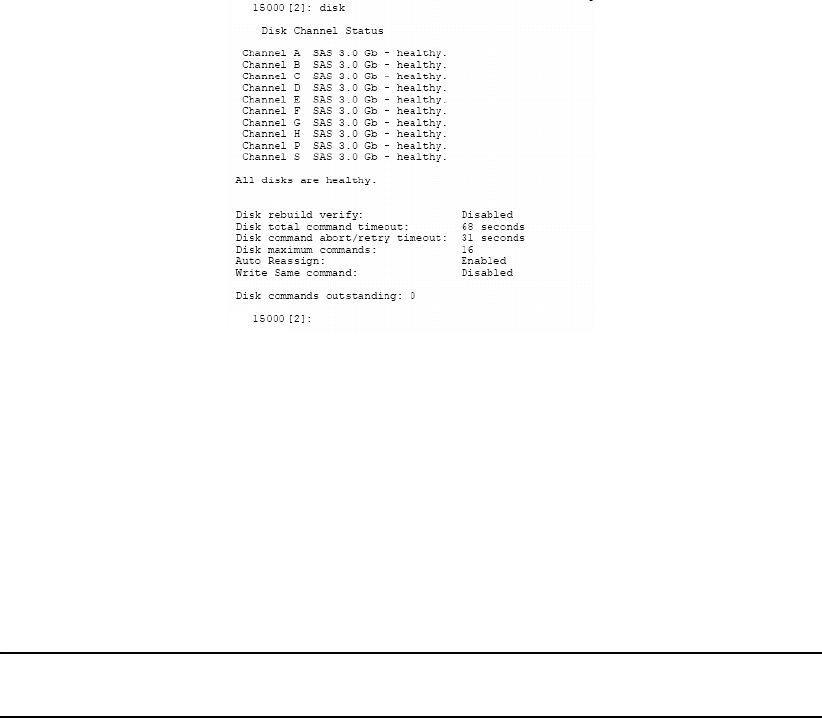
Controller Management
007-5510-002 57
If the MF (Multiplication Factor) parameter is OFF, the system will only prefetch the number of blocks
specified by PREFETCH after every read command. If the MF parameter is ON, then the system will
multiply the transfer length of the command by the prefetch value to determine how much data will be
prefetched. A prefetch value of less than 8 is recommended when the MF parameter is ON.
CACHE MF=ON|OFF enables/disables the MF bit on the specified LUN. Default is ON.
The Maximum Prefetch Ceiling parameter sets the maximum prefetch ceiling in blocks for prefetches
on read commands. It sets an upper limit on prefetching when the MF parameter is ON. The system will
automatically limit the amount of prefetching if the system is running low on resources.
CACHE MAX=x (where X is a range from 0...65535) sets the maximum prefetch ceiling in blocks for
prefetches on Read commands for the specified LUN. Valid range is 0 to 65535. Default setting is 65535.
3.3.1.4 Cache Settings Reset
CACHE DEFAULTS loads the default settings for all of the cache parameters for the specified LUNs.
Disk Configuration Settings
The DISK command displays the current disk configuration settings (Figure 3–30).
Figure 3–30 Disk Configuration Setting Screen
The writeback cache and disk timeout settings can be configured manually.
DISK TIMEOUT=x sets the disk timeout for an I/O request in seconds. Valid range is 1 to 512 seconds.
Default setting is 68 seconds.
DISK CMD_TIMEOUT=x sets the Retry Disk timeout (in seconds) for an I/O request. The retry timeout
value indicates the maximum amount of time that is allotted to receive a reply for each retry of an I/O
request. If the I/O request does not complete within this time, it is aborted and potentially retried: if there
is still time remaining in the overall disk timeout to allow for another retry, it is retried; if not, it
completes with an error status.
NOTE :
The DISK CMD_TIMEOUT value must be smaller than or equal to DISK TIMEOUT.
Valid range is 1 to 512 seconds.
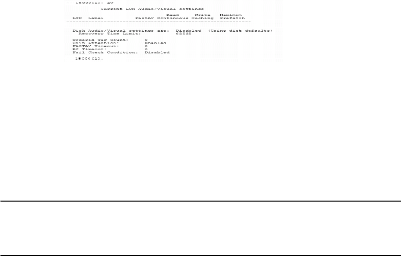
58 007-5510-002
3.3.2 Audio/Visual Settings of the System
The audio and visual (AV) settings of the system and the disks can be tuned to provide better
performance and a lower latency. The writeback and prefetch settings for each LUN are changed with
the CACHE command.
The AV command displays information about the audio/visual settings of the system (Figure 3–31).
Figure 3–31 Current Audio/Visual Settings
AV FASTAV=ON|OFF enables/disables the disk fast audio/video read options for streaming data. When
enabled, the system will start the data transfer for read operations before all of the disk commands have
finished. This feature reduces the latency for read operations but the system will be unable to check the
integrity of the data. This parameter is saved on a LUN by LUN basis. Use LUN=X command to change
the settings for a single LUN. Default setting is OFF.
NOTE :
When FASTAV mode is enabled, the controller no longer checks data in real-time.
Changing the disk parameters can adversely affect the I/O operation of the system. This
parameter should only be adjusted when the system is idle. Default setting is OFF.
FASTAVTIMEOUT=x sets the timeout before the FASTAV option activates on a host read command.
The FASTAV mechanism is not used until the host command takes longer than the timeout value. A
value of zero indicates that the system starts the data transfer as soon as a minimum number of drives are
ready. This value is in 100 millisecond increments. The range for “x” is 0 to 255. The default is 50.
ORDEREDQUEUE=x enables the use of ordered tags when communicating with the drives. The value
“x” indicates the number of disk commands that can be sent before an ordered tag must be sent to the
disks. Valid range is 0 to 255. Default is 0.
UA=ON enables the initial Unit Attention condition when an initiator logs into the system; the system
reports a Unit Attention condition on the first SCSI command after the initiator logs in. Default is ON.
UA=OFF disables the initial Unit Attention condition when an initiator logs into the system; the system
automatically clears the unit attention condition when an initiator logs in.

Controller Management
007-5510-002 59
RC=ON|OFF enables the Read Continuous (RC) option for Audio/Video streaming data; the system
starts the data transfer for read operations after RCTIMEOUT is reached, even if the disks commands
have not finished. Use this to reduce the latency for read operations in Audio/Visual environments where
latency is more important than data integrity. This parameter is saved on a per-LUN basis. Use in
combination with the LUN=x parameter to change the settings for a single LUN. Enabling this feature
automatically enables FASTAV.
WARNING! This feature allows the system to return invalid data to the initiator.
RCTIMEOUT=x Default setting: disables the Read Continuous option for Audio/Video streaming data.
Note: This parameter is saved on a per-LUN basis. Use in combination with the LUN=x parameter to
change the settings for a single LUN.
LUN=x sets the host command timeout for the Read Continuous option for Audio/Video streaming data.
Set to 0 to disable the Read Continuous feature in the system. This value is in 100 millisecond
increments. The range for 'x' is 0 to 255. The default is 8.
FAILCC=ON instructs the host ports to report a check condition for all SCSI commands when the unit
is in a failed state. This command should only be used in AV environments when a check condition is
required instead of taking the unit off the loop.
FAILCC=OFF This is the default setting. Host ports will NOT report a check condition for all SCSI
commands when the unit is in a failed state.
3.3.3 Locking LUN in Cache
Locking a LUN in data cache will keep all of the data for the LUN in the cache for faster access. Once
a LUN is locked, the data that is gathered to service read and write commands will stay permanently in
the cache. The controller will continue to fill up the cache until 50% of the total cache is filled with data
from locked LUNs, while the other 50% of the cache is reserved to service I/O for unlocked LUNs.
For example, when a host issues a read command for data from LUN 1 that has been locked in cache, the
following will occur:
• The controller reads data from disks, locks data in cache, and sends data to host
• Any reads of the same data will be serviced from cache, which provides faster access than reading
from disks.
Once the size of the locked LUNs exceeds 50% of the total cache, the controller must create cache space
to process a new I/O by removing older data from the locked portion of cache. The Least Recently Used
(LRU) algorithm is used to determine which locked data to remove from cache.
50% of Data Cache used
to service Locked LUNs
50% of Data Cache used
to service Unlocked LUNs
Initial Cache
Unlocked LUN data Unallocated
cache* Data for
LUN 1
* Unallocated cache can be used for unlocked LUNs’ or locked LUNs’ data.
Once cache has been allocated to a locked LUN, however, it cannot be used
by an unlocked LUN.
Cache allocation after I/O completes

60 007-5510-002
For example, LUNs 0 to 3 are locked in cache and all 50% of the total cache has been filled by data from
LUN 0, 1, and 2.
When a host issues a read command for data from LUN 3, the following will occur:
• The controller unit determines which data to remove from the locked portion of cache, using the
LRU algorithm. The LRU algorithm is thus: If LUN 0 has not been accessed for 1 hour, LUN 1
has not been accessed for 30 minutes, and LUN 2 has not been accessed for 2 minutes, then
LUN 0’s data will be removed from cache because it is the least recently used data.
• The controller reads data from disks, locks data in cache, sends data to host.
• Any reads of same data will be serviced from cache (until data is removed from cache due to its
being the least recently used data).
3.3.3.1 Locking / Unlocking a LUN
To lock a LUN in the data cache, enter:
LUN LOCK=X<Enter>
where “X” is the Logical Unit number <0..1023> (Figure 3–32).
Figure 3–32 Logical Unit Status - LUN Locked in Cache
LUN UNLOCK=x unlocks a LUN and releases its cache locked by the LUN.
3.3.3.2 System Performance Statistics
The controller monitors pre-fetch and cache efficiency, request distribution, transaction, and transfer
rates by port.
The STATS command displays the Performance Statistics for the host ports, disk channels, and cache
memory (Figure 3–33). It will show the read and write performance of each of the host ports.
Unlocked LUN data Data for
LUN 2
Initial Cache
Data for
LUN 0 Data for
LUN 1
Cache allocation after I/O completes
Unlocked LUN data Data for
LUN 2
Data for
LUN 3 Data for
LUN 1
Logical Unit Status
Block
Size
LUN Tiers Tier ListCapacity
(Mbytes)
512
-------------------------------------------------------------------------
10002Cache Locked0
System Capacity 277810 Mbytes, 237802 Mbytes available.
Status
3 1 2 3
51210002Ready13 1 2 3
51210002Ready23 1 2 3
51210002Ready33 1 2 3
15000 [1]: lun lock=0
Owner
1
1
1
1
Label
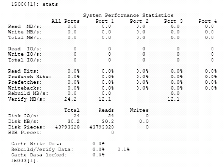
Controller Management
007-5510-002 61
Figure 3–33 System Performance Statistics Screen
Read Hits shows the percentage of Read I/O requests where the data was already in the cache. Prefetch
Hits shows the percentage of Read I/O requests where the data was already in the cache due to
prefetching. Prefetches shows the percentage of host Read I/O requests to the disks due to prefetching.
The bottom of the screen displays the Read and Write performance of the disks. Disk Pieces shows the
total number of disk I/O requests from the host ports. The system will combine several host I/O requests
into a single disk I/O request. The histogram at the lower right shows how often this is occurring for reads
and writes. BDB Pieces is the number of host I/O blocking and deblocking requests.
Cache Writeback Data shows the percentage of the cache which contains writeback data that must be
written to the disks. Cache Rebuild Data shows the percentage of the cache in use for rebuild operations.
Cache Data Lock shows the percentage of the cache which is locked by the locked LUNs.
STATS CLEAR resets all the statistics back to zero.

62 007-5510-002
STATS DELAY displays a histogram of the time it takes for the host and disk I/O requests to complete
in 100 msec intervals (Figure 3–34).
Figure 3–34 Command Delay Statistics Screen
Command Delay Statistics
Time
15000 [1]: stats delay
Host Host Disk Disk
seconds Reads Writes Reads Writes
1690087 1446110 281633 2537040.1
82900 79522 87112 452600.2
389 263 13243 77280.3
64 77 3319 31490.4
12 24 970 14350.5
5 7 336 6720.6
0 8 92 3440.7
0 4 38 1360.8
0 3 13 840.9
0 9 8 84451.0
634241.1
9192141.2
12 15 1 181.3
12 17 0 101.4
12 19 0 91.5
7320 01.6
14 34 0 01.7
22 12 0 01.8
23 12 0 01.9
56 19 0 02.0
175 4 0 02.1
70 1 0 02.2

Controller Management
007-5510-002 63
STATS HOSTDELAY displays a histogram of the time delay between when the last data transfer is set
ready and the host command completes (Figure 3–35). The host ready delay information is shown in
100msec intervals.
Figure 3–35 Host Delay Statistics Screen
STATS TIERDELAY=<tier> displays a histogram of the time it takes for the disk I/O request to complete
for all the disks in the specified tier (Figure 3–36). If no tier is specified, all valid tiers will be displayed.
Figure 3–36 Tier Delay Statistics Screen
Host Command Ready Delay Statistics
Time
15000 [1]: stats hostdelay
Port 1
seconds Reads Writes
Port 2
Reads Writes
Port 3
Reads Writes
Port 4
Reads Writes
0.1 00000000
0.2 00010000
0.3 00012100
0.4 00120200
0.5 00000000
0.6 00010200
0.7 00010200
0.8 00000000
0.9 00000000
1.0 00000200
1.1 00000000
1.2 00000100
1.3 00002100
1.4 00002100
1.5 00000000
1.6 00000000
Tier 1 Delay Statistics
Time
15000 [1]: stats tierdelay
Disk Channels
seconds A BCDEFGHPS
0.1 3407b 33108 339bd 3409f 572c5 34c0d 33640 30603 3391a 7ed5d
0.2 480f4 4885c 4866a 48190 27b83 47910 484cc 4acc1 48196 21e
0.3 2ca6 33d8 2def 2c1f 127 2928 324f 3a63 32a7 0
0.4 d1 1bc cd c7 0 c0 185 10f 176 0
0.5 2c 2b 26 12 0 23 27 33 36 0
0.6 13 1b 14 12 0 e 13 1d 1d 0
0.7 13157a6e1528170
1.8 0000000000
1.9 0000000000
2.0 0000000000
....
Hit enter to continue, ‘e’ to escape:

64 007-5510-002
STATS DISK displays a histogram of the disks in the system that have taken an unusually long time to
complete an I/O request (Figure 3–37). The count is incremented for a disk if that disk takes longer than
the other disks to finish an I/O request. This command is used to determine if a disk in the array is slowing
down system performance.
Normally all the disks in a tier should have similar counts. A disk with a significantly higher count
indicates that the disk may be slower than the other disks or have problems.
Figure 3–37 Host Command Offsets Screen
Delayed Disk Command Counts
15000 [1]: stats disk
0ABCDEFGHPS
10000000000
2 3C5 392 34D 4DC 37C 361 3BD 3EE 48B 0
30000000000
4 421 7F7 37F 396 7DB 3D2 5B6 3C6 55E 0
50000000000
6 338 37E 37F 36C 30F 38B 8DF 5D1 58E 0
70000000000
80000000000
9 3F1 347 6D4 7DD 929 357 3B4 4D4 5FA 0
10 78C 3B3 412 2ED 642 40A 788 33B 43E 0
11 465 3EE 739 34C 2FC A2F 358 310 382 0
120000000000
Disks in the same tier should have similar results.
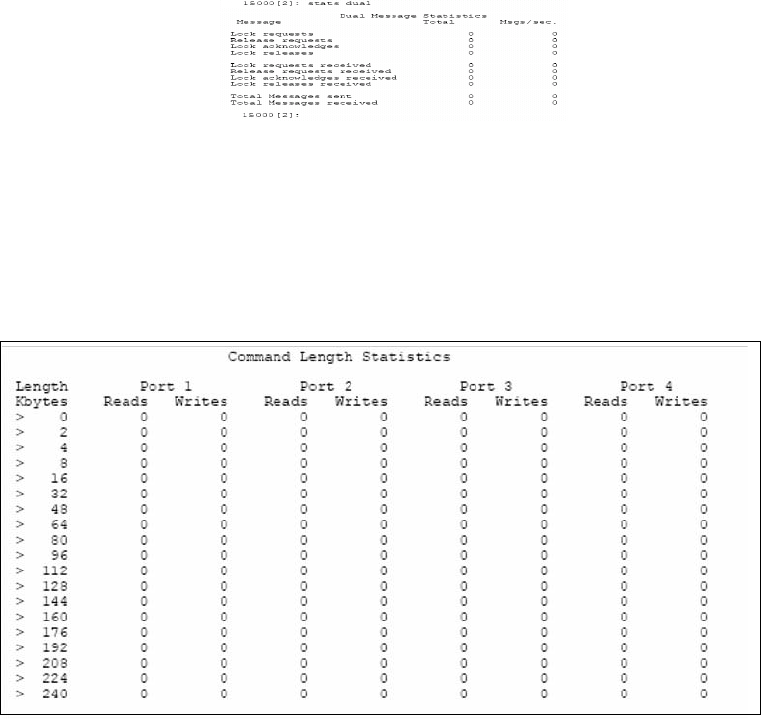
Controller Management
007-5510-002 65
STATS DUAL displays the statistics for the dual mode messages (Figure 3–38).
Figure 3–38 Dual Message Statistics Screen
STATS LENGTH displays a histogram of the length of the host I/O requests in 16 kb intervals (Figure
3–39).
Figure 3–39 Command Length Statistics Screen
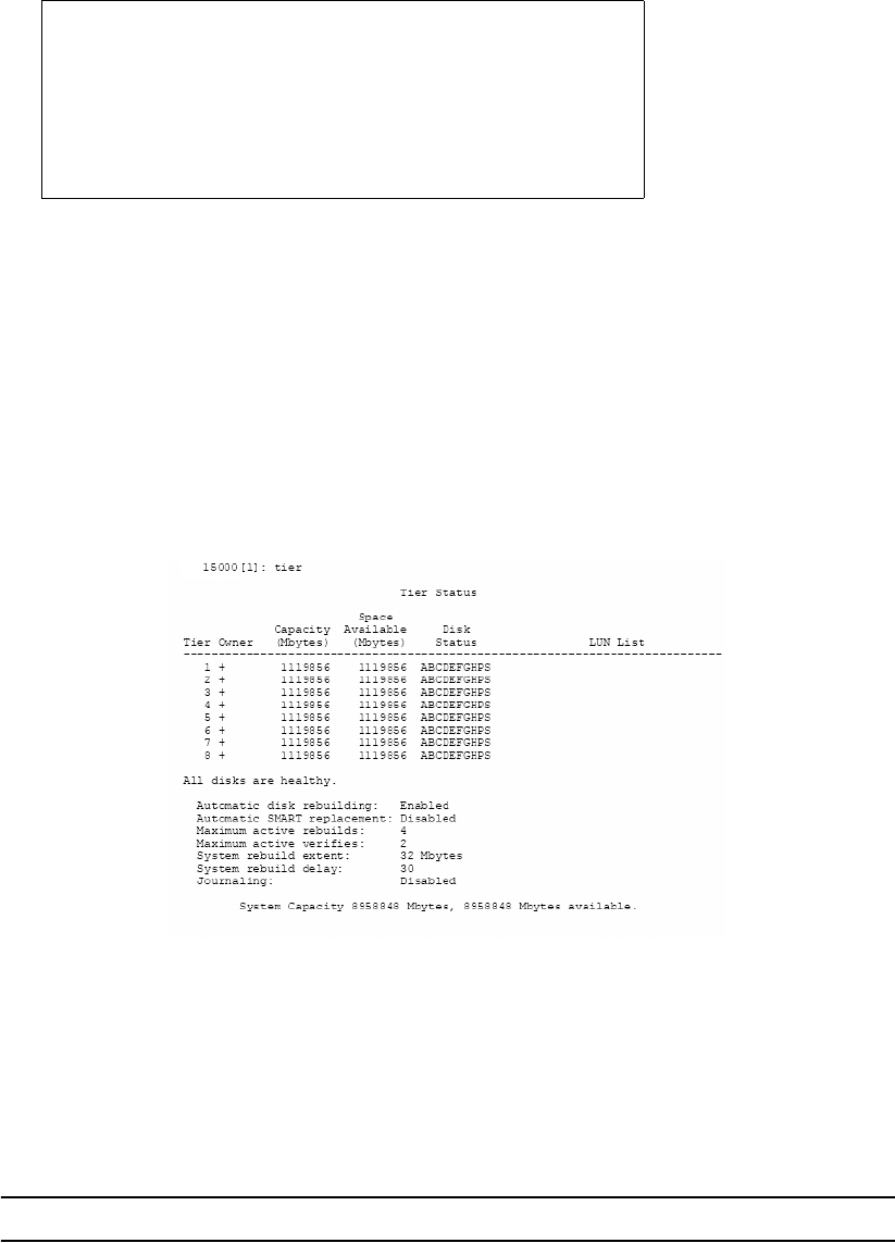
66 007-5510-002
STATS OFFSET displays a histogram of the offset of the host I/O requests into the cache segments
(Figure 3–40). Host I/O requests with offsets that are not in the 0x0 column may require blocking/
deblocking which can slow down the performance of the system.
Figure 3–40 Host Command Offsets Screen
STATS REPEAT=OFF|MBS|IOS allows you to enable/disable the repeating statistics display where
MBS displays MB/s, IOS displays IO/s, and OFF turns off (both) the repeating displays.
3.3.4 Resources Allocation
Background Format/Rebuild Operations
Format and rebuild operations are background processes; their rates can be adjusted to minimize their
impact on system performance.
Figure 3–41 Displaying the Current Rebuild Parameters
TIER displays the current rebuild parameter settings for the system (Figure 3–41).
The TIER DELAY parameter controls the amount of system wait time before rebuilding the next chunk
of data. This parameter slows down the rebuild and format operations so they will not affect the
performance of the system. TIER DELAY=0 will remove many delays so the rebuild and format
operations will go as fast as possible, but this could significantly affect the performance of the system.
NOTE :
A delay value less than 1 (<1) is not recommended.
Host Command Offsets
15000 [1]: stats offset
x0 x1 x2 x3 x4 x5 x6 x7
0 720943 8 11 5 0 2 0 343AAD2
8 3FE8E9 5 10 1 0 2 0 3486F35
10 42754D 3 6 0 0 4 1 39B0635
18 4AA571 1 4 2 0 6 0 40677A9
Most commands should be in column 0 or 4 for the best performance.

Controller Management
007-5510-002 67
TIER DELAY=x is used to set the system rebuild/format delay. This value is in 100 millisecond
increments. The range is 0 to 1000. The default setting is 30 milliseconds (3 seconds).
The REBUILD EXTENT parameter determines how much data to rebuild or format at one time. A small
EXTENT value will slow down the rebuild and format operations so they will not affect the performance
of the system. Increasing the EXTENT value will allow more data to be rebuilt in a single pass. The
recommended setting is to use the default value of 32 MBytes (MBs) and only adjust DELAY to match
your user load.
TIER EXTENT=X (where X is a value from 1 to 128) sets the system rebuild/format extent in MBs. The
range is 1 to 128 MBs. Default is 32MBs.
3.3.4.1 Background LUN Verify Operations
LUN VERIFY displays the current setting for background verify on all LUNs.
LUN VERIFY=X turns on background verify for LUN X, where X is a Logical Unit <0..1023>.
LUN VERIFY=ON|OFF prompts you for a list of LUNs where the background verify will be turned either
ON or OFF.
LUN VERIFY=ON will both turn on the background verify for the specified LUN(s), as well as start up
the verify operation(s).
LUN VERIFY=OFF only turns off the Background Verify setting for the specified LUN(s). Therefore,
any Verifys that are already active on the LUN(s) will not terminate until after the completion of that
Verify's current iteration. To stop all verify operations immediately, use the LUN STOP command.
NOTE :
It is recommended that you run LUN VERIFY in continuous mode, since it can help
increase disk reliability.
LUN DELAY= X sets the system Verify Delay value to X, where x is a value from 0 to 1000. The Verify
Delay value determines how long a verify operation will pause after it reaches the verify extent. This
parameter slows down the verify operation so that it will not affect the performance of the system (except
in the case where X is set to 0, as described below).
DELAY=X will remove all delays so that the verify operation will go as fast as possible; however, this
will slow down the performance of the system. This value is in 100 millisecond increments. The range
for X is 0 to 1000. Default is 40.
LUN EXTENT=X sets the system verify extent value X in Mbytes. The verify extent determines how
much data can be verified before the verify operation must pause. This parameter slows down the verify
operation so that it will not affect the performance of the system. Increasing the extent value will allow
more data to be verified in a single pass. The range for X is 1 to 128 MBs. Default is 32 MBs.
3.3.4.2 Background TIER Verify Operations
TIER VERIFY verifies LUNs on a tier by tier basis. TIER VERIFY differs from LUN VERIFY in that the
number of simultaneous Tier Verifys is limited to a value that is set by TIER MAXVERIFIES (default =
2) parameter. The valid range is 1 to 16. If a tier is marked for continuous verification, once the
verification completes, the next sequential tier marked for verification, not presently being verified, will
start.
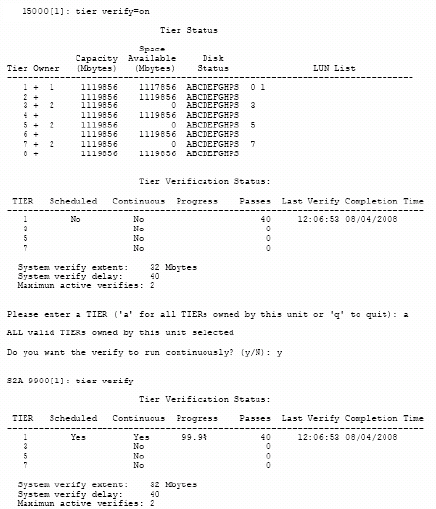
68 007-5510-002
TIER VERIFY Displays a summary of verifications.
To enable Tier Verify (Figure 3–42):
1. At the prompt, type TIER VERIFY=ON <Enter>.
2. The system will ask which tier you wish to verify. Enter the tier number or type a for “All.”
3. The system will ask if you want run the Tier Verify operation continuously or not. Type y to run
continuously or N to run just once. The default is N.
Figure 3–42 Tier Verify ON Screen
To disable Tier Verify (Figure 3–43):
1. At the prompt, type TIER VERIFY=OFF <Enter>.
2. The system will ask which tier you wish to verify. Enter the tier number or type a for “All.”
Tier Verify will be disabled off after the next iteration has completed.
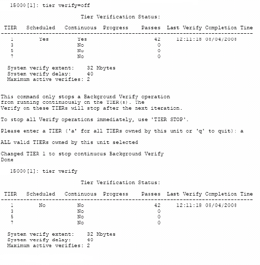
Controller Management
007-5510-002 69
Figure 3–43 Tier Verify OFF Screen
TIER VERIFY=X A specified tier will be verified if possible.
These API and CLI commands will affect the TIER verification process:
• The CLI commands TIER PAUSE, TIER RESUME, TIER STOP.
• The API command TIER STATUSCHANGE.
LUN operations (add, delete, move) can affect TIER VERIFY operations. As tiers are verified, only
LUNs that are valid and formatted are verified.
If a tier is owned by the other unit, and it is healthy, the user is notified that the verification cannot occur
due to the ownership of the tier. The user can then retry the verification on the other unit.
The verification of LUNs on a tier is performed in the order of addressing on the tier. Only valid and
formatted LUNs can be verified.
3.3.4.3 Rebuild Journaling
The rebuild journaling feature is intended to speed the recovery from disk-side loss of communication
problems. A loss of communication includes, but is not limited to, SAS expanders, hardware/software
failures, and SAS cable failures, and SFP failures.
Currently, when the controller encounters a loss of communication with a drive or a group of drives on
a SAS link, the software fails the drive(s) and continues operation. When cache coherency is enabled,
if either controller encounters a loss of communication with a drive, the firmware will fail the drive. This
allows a controller unit to maintain operation during disk-side events. Once the loss of communication
is resolved, however, the controller must rebuild all the affected drives. For large installations, a loss of
70 007-5510-002
communication, such as a cable failure, can cause the controller to fail numerous disk drives. Once the
loss of communication is resolved, the time to rebuild all the failed drives can take many weeks.
The rebuild journals contain bitmaps that indicate which portions of the disks in a tier have been updated
with new data while a disk was failed or replaced. The system uses the information in the journals to
reduce the rebuild time of drives that have not been swapped out. This can dramatically lower rebuild
time, since only portions of the tier may have been updated while the drive was failed or replaced.
The granularity of the journal will be 4MB of data on a single disk or 32MB of host data. Thus a single
host write will force the system to rebuild a minimum of 4MB of data on the disk. A new host write into
a 4MB section that has already been journaled will not cause a new journal entry. The system will
automatically update journals when disks are failed or replaced regardless of whether journaling is
enabled.
To ensure that the journals are correct, the system carefully monitors the state of the journals and will
automatically invalidate or disable the journals if it detects a condition where the journal cannot be used
or journal information could potentially be lost.
The following summarizes the limitations that apply to journaling:
• Rebuild journaling will automatically be disabled if the failed disk is swapped with a new disk. The
system will track the serial number of the disks when they are failed and will force a rebuild of the
entire disk if the serial number changes.
• Rebuild journaling will not be used when a failed disk is replaced by a spare. The rebuild journal
can be used when rebuilding a replaced disk that has not been swapped.
• The system will invalidate the journal on tiers that have failed or replaced disks on boot up. This is
required because the system does not save the journal information.
• Rebuild journaling will be managed by the controller that owns the tier. If a controller is failed, then
the journals on the tiers owned by that controller will be invalidated.
• The system tracks the original owner of a tier when a drive is failed so changing the ownership of
the tier will disable use of the journal for rebuilds on that tier.
• Rebuild journaling will be disabled when rebuilding disks that are failed due to a change in the
parity mode of the tier.
• Use of the rebuild journal will be temporarily disabled if the system is rebuilding a LUN that is a
backup LUN in a mirror group.
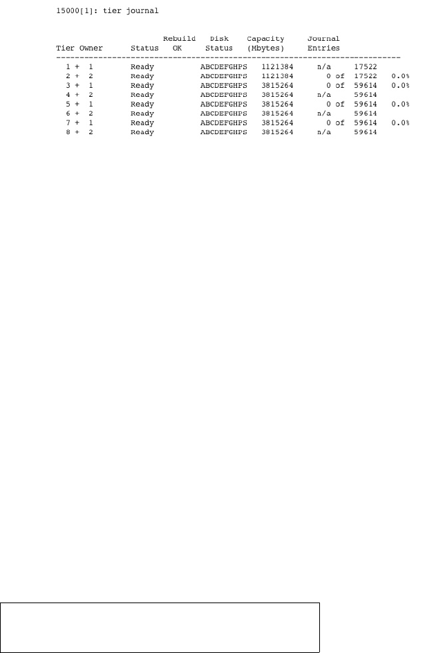
Controller Management
007-5510-002 71
To display the information about the rebuild journal, use the TIER JOURNAL command (Figure 3–44).
To display the information for a specified tier, use the TIER JOURNAL=t command, where t is the
specified tier. This screen will give detailed information about the status of the journal and a display of
all the journal entries for the tier. This screen will also give more detailed information on the status of
the journal and will indicate why it was disabled or invalidated.
Figure 3–44 Sample Tier Journal Command Screen
The status field indicates the current status of the journal:
• Ready - The journal is waiting for updates.
• Active - A disk is failed and the journal has updates.
• All other statuses indicate why the journal cannot be used.
The Rebuild OK field indicates if a rebuild can use the journal:
• Off - Journaling not enabled. Use JOURNAL=ON to enable.
• Yes - Journaling can be used when rebuilding.
• No - Journaling cannot be used.
The rebuilds will only use the journals if the “Rebuild OK” field indicates “Yes”. In order to use
journaling on rebuilds, the operation must be manually started using DISK REBUILD=tc where 't'
indicates the tier, and “c” indicates the channel or REBUILD=ALL which will start a rebuild on all disks.
The TIER JOURNAL=ON|OFF command enables/disables use of the journals during rebuild operations.
The system will automatically update the journals when disks are failed or replaced regardless of this
setting. This parameter only indicates if the journal can be used during the rebuild. The default is OFF.
3.3.4.4 SES Device Monitoring Rate
The SES device monitoring rate can be adjusted to minimize its impact on system performance. SES
M_WAIT displays the current setting in seconds (Figure 3–45).
Figure 3–45 SES Device Monitoring Rate
SES M_WAIT=x sets the SES device monitoring rate for the system in seconds. Valid range is 4 to 90.
The default monitoring rate is 6 seconds.
15000 [1]: ses m_wait
SES timer m_wait = 6 seconds
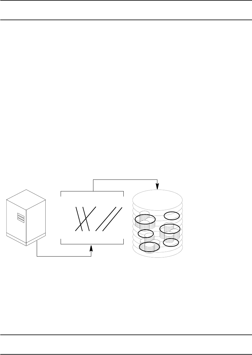
72 007-5510-002
NOTE :
Improper use of the SES M_WAIT command can prevent the SES monitors from
detecting an enclosure fault before the enclosure automatically shuts down.
3.3.4.5 Host Command Timeout
The Host Command Timeout parameter allows the system to free up resources and make them
available to other users if the request from a particular user cannot be completed. This helps to improve
performance in a SAN environment where there are a lot of users accessing the storage.
HOST TIMEOUT=X (where X is value range 1..512) lets the host command timeout for an I/O request
in seconds. Valid range is 1 to 512 seconds. Default setting is 75 seconds.
3.4 Security Administration
The controller’s dual-level, non-host based data security is maintained with scalable features including
restricted management access and authentication against authorized listing. No security software is
required on the host computers. (Refer to Section 3.1.3,"Administrator and User Logins" for information
regarding Telnet and serial port security.)
Each authorized user will have its customized LUN identification scheme which applies to all host ports
(Figure 3–46).
Figure 3–46 Mapping Internal LUNs to External LUNs
Read-only and read/write privileges can be specified for each LUN and for each user.
The “place holder” LUN feature allows the controller administrator to map a zero capacity LUN to a host
or group of hosts (via zoning or user authentication). The administrator can then create a real LUN and
map it to the host(s) to replace the “place holder” LUN in the future. In most cases, the host will not have
to reboot since it already mapped to the “place holder” LUN.
NOTE :
Support of place holder LUNs is dependent upon the operating system, the driver, Host
Card Adapter (HCA), and host bus adapter.
LUN 0
LUN 2
LUN 4
LUN 3
LUN 5
LUN 1
Internal
LUN Map
WWN 1
WWN 1
External
LUN Map
01234567
01234
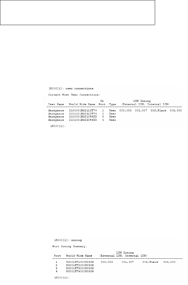
Controller Management
007-5510-002 73
3.4.1 Monitoring User Logins
The AUDIT function continuously monitors logins to the controller and provides alerts in the event of
unauthorized login attempts (Figure 3–47).
Figure 3–47 User Login Messages
USER AUDIT=ON|OFF enables/disables the user auditing function. When enabled, the system will
display a message when a user logs in or out. Default is OFF.
USER CONNECTIONS displays a list of all the currently connected users and the host port to which the
user is connected (Figure 3–48).
Figure 3–48 User Connections Screen
3.4.2 Zoning (Anonymous Access)
This type of configuration provides the first-level protection. The LUN identification scheme can be
customized for each host port. Any unauthorized user accessing the controller will be considered
“anonymous” and granted the zoning rights for the host port to which they are connected.
The ZONING command will display the current settings for the host ports. The LUN Zoning chart
indicates which internal LUNs the users will be able to access (with Read-only and Read/Write
privileges) and where the internal LUN will appear to the users. In Figure 3–49, only internal LUN 1
can be accessed and it is read-only. It will appear as LUN 0 to the users.
Figure 3–49 Current Zoning Configuration Screen
ZONING EDIT lets you change the settings for the host ports. You will be asked to select a host port to
change and enter the mapping for each LUN (Figure 3–50). The default configuration is to deny access
to all the LUNs.
ZONING DEFAULT restores the zoning of a host port back to its default settings.
Host Int 15:04:07 User Logout Client1, port:4 S_ID:000004
Host Int 15:04:47 Authenticated Login Client10, port:3 S_ID:000002
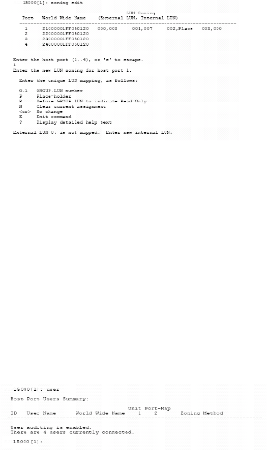
74 007-5510-002
Figure 3–50 Edit Zoning Configuration Screen
3.4.3 User Authentication
The controller creates correspondence between users (World Wide Name or GUIDs), storage LUNs, and
permissions. The system can store configurations for up to 512 users in total, and the settings apply to
all host ports.
Each authorized user will only have access to their own and “allowed-to-share” data determined by their
customized LUN identification scheme. Administrators can also restrict users’ access to the host ports
and their Read/Write privileges to the LUNs. Unauthorized users will be given the “host port zoning”
rights as defined in Section 3.4.2,"Zoning (Anonymous Access)".
USER displays the current settings for all authorized users (Figure 3–51). Each user is identified by their
64-bit World Wide Name (or GUID) and is given a unique user ID number. The Ports column indicates
which host ports, on each controller, the user is allowed. The LUN Zoning chart indicates which internal
LUNs the user will have access to (with read-only and read/write privileges), and where the internal LUN
is displayed to the user.
Figure 3–51 User Settings Screen
To configure/change the settings, use these commands:
•USER ADD adds a new user and defines the user’s access rights
•USER EDIT edits the access rights of an existing user
•USER DELETE deletes an existing user from the system.
See Section 2.3.9, "Setting Security Levels", subsection entitled User Authentication (Recommended
for SAN Environment) for further information on how to add a new user.
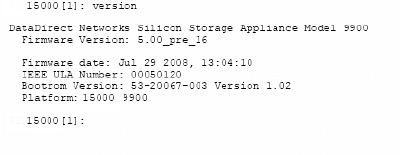
Controller Management
007-5510-002 75
3.5 Firmware Update Management
SGI periodically releases firmware updates to enhance features of their products. Contact SGI technical
support to obtain the latest firmware files.
3.5.1 Displaying Current Firmware Version
The VERSION command displays version information of the controller’s hardware and firmware
(Figure 3–52).
Figure 3–52 Version Information Screen
3.5.2 Firmware Update Procedure
TFTP enables the administrator to download the new controller firmware from a TFTP server to the
controller. When using the TFTP command, a TFTP server must be running and a copy of the firmware
file image must be on the TFTP server. This command will “fail” the current controller and should not
be used during active I/O.
Follow these steps to update the firmware files.
1. Collect and save the output of the following commands before you update the firmware:
VERSION AV CACHE
DISK DISK LIST DUAL
HOST HOST STATUS LOG
LUN LUN CONFIG NETWORK
STATS STATS DELAY STATS TIER DELAY
TIER TIER CONFIG
2. Copy the new firmware file to your TFTP server.
3. Connect to the controller via Telnet or serial (CLI port).
4. Enter TFTP
5. You will be asked to confirm action (Figure 3–53). Enter y to continue.
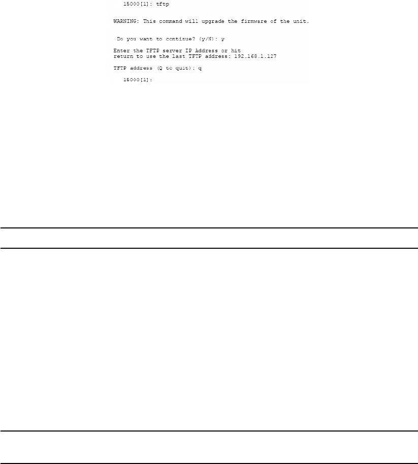
76 007-5510-002
Figure 3–53 Downloading Controller Firmware
6. Enter the TFTP server’s IP address: TFTP <IP_address>
7. Enter the firmware path and filename: TFTP <filename>
8. For the couplet controller configuration, connect and log into the other controller. Repeat Steps 4-
7 above to update the firmware.
9. Enter RESTART to restart the unit(s).
NOTE :
RESTART can be done at a later time.
10. (For dual mode only): After both controllers are back on-line, use the DUAL command to verify
that both controller units are healthy. If either controller shows failed, login to the healthy
controller and issue the DUAL HEAL command.
3.6 Remote Login Management
TELNET ENABLE allows the administrator to temporarily enable the establishment of a remote Telnet
session. Use the TELNET command to display the current setting.
TELNET DISABLE allows the administrator to temporarily disable the establishment of a remote Telnet
session.
NOTE :
Telnet capability is reset to ON after a controller restart. To turn off Telnet access
permanently, use the NETWORK command.
TELNET STATS allows the administrator to view various statistics maintained on remote Telnet
sessions (Figure 3–54). These statistics are kept from the time that the system is powered on.
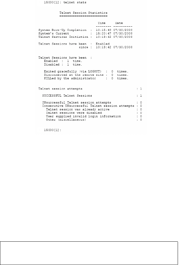
Controller Management
007-5510-002 77
Figure 3–54 Telnet Statistics
The administrator is strongly advised to perform any commands affecting the system’s configuration
from the CLI UART only (and not from a Telnet session), and to only perform such commands after
issuing the TELNET DISABLE command, so that remote users cannot log into the system in the middle
of an administrative command.
3.6.1 When a Telnet Session is Active
Whenever a remote Telnet session is active, the current RS-232 console switches to a CLI sub-shell
which allows the administrator to enter a very limited sub-set of the CLI commands. The following
message is displayed on the console when a Telnet session is initiated from a remote site (Figure 3–55).
Figure 3–55 Telnet Session Initiated
15000 [1]:
New TELNET Session initiated from IP address: 010:123:139:005
[Remote TELNET session ON] Local SUBshell 15000 [1]:
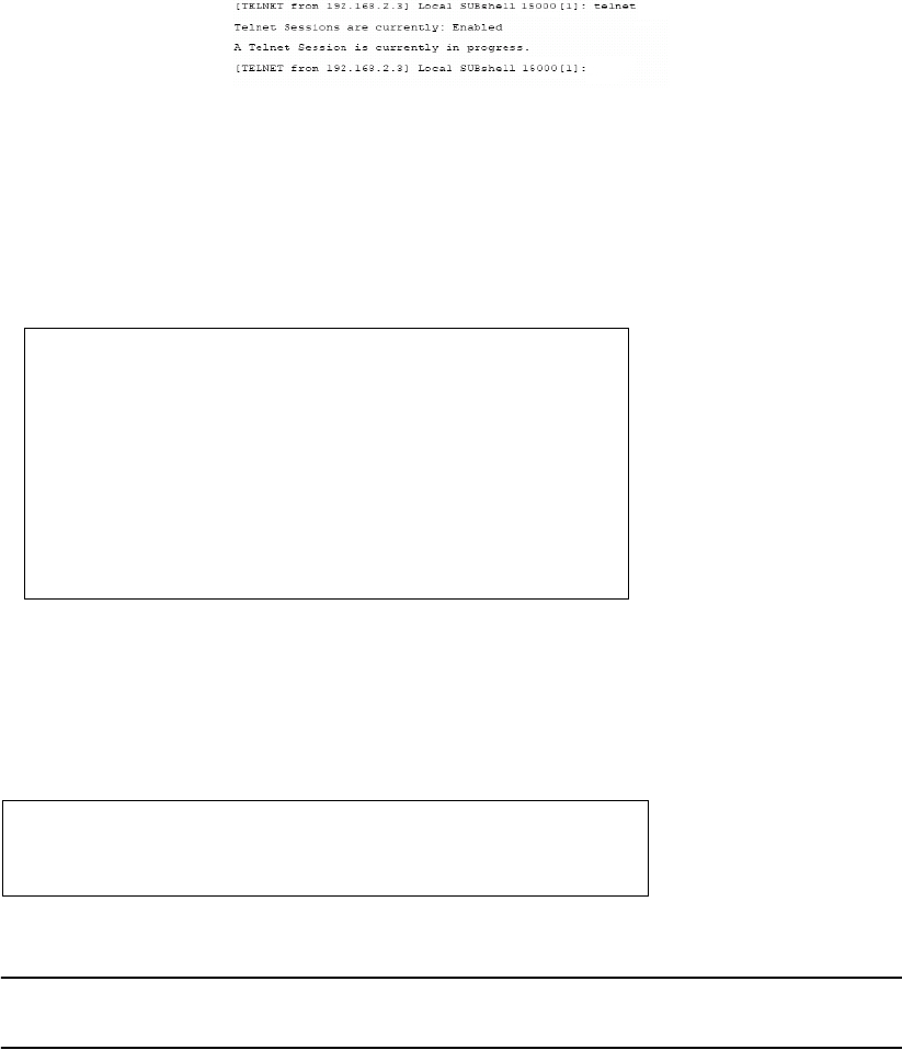
78 007-5510-002
Within the CLI subshell, the TELNET command allows the administrator to view information regarding
the currently active Telnet session (Figure 3–56).
Figure 3–56 Telnet Session Information
TELNET KILL=m lets the system administrator terminate the remote Telnet session (Figure 3–57). The
KILL parameter may also be specified with TELNET KILL=m, where m indicates the number of minutes
that will be allowed to elapse before the remote Telnet session is terminated. The valid range is
<0..15> minutes. Default is 1 minute. An administrative login is required before the command is
processed.
Figure 3–57 Terminating a Telnet Session
The remote user is given a warning that the administrator has killed his session, and indicates to him the
amount of time (if any) that he has remaining (Figure 3–58). An m value of 0 (zero) is an immediate
KILL. The remote user will be notified, but most likely will be unable to read the entire warning message
before the session ends.
Figure 3–58 Telnet Session Being Terminated
NOTE :
If a user is in the middle of running a CLI command at a remote Telnet site when the
administrative KILL is issued, the command will continue on the CLI console.
[Remote TELNET session ON] Local SUBshell 15000 [1]: telnet kill=1
-- WARNING --
Any CLI command that may be in progress on the remote Telnet site
Enter the administrative (or higher) login name: admin
Enter the appropriate password: ********
will need to be completed locally after the remote session has been
terminated.
-- Please wait for the remote TELNET session to be terminated. --
.........................
Telnet Session termination.
15000 [1]:
-- The System Administrator will terminate this TELNET Session in 30 seconds --
Connection closed by foreign host.
-- The System Administrator will terminate this TELNET Session in 1 minute --
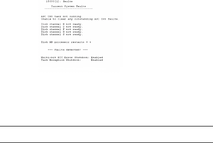
Controller Management
007-5510-002 79
3.7 System Logs
3.7.1 Message Log
All controller events are logged and saved in non-volatile memory. The log will automatically roll over
when it is full.
LOG displays the log of previous system messages.
LOG CLEAR clears the log of all previous messages.
LOG CHECKCONDITION displays the Check Condition log.
LOG CHECKCONDITION=MORE will display additional information concerning the check condition.
LOG CHECKCLEAR clears the Check Condition log, enter LOG CHECKCLEAR.
LOG QUIET= ON|OFF. This Administrator command enables a “quiet mode” on the CLI where
Message Log statements will still be logged, but not displayed.
LOG QUIET will display the current state of the Log Quiet mode. There should be the word “Quiet” at
the CLI prompt when the Log Quiet mode has been enabled.
3.7.2 System and Drive Enclosure Faults
Use the FAULTS command to display a list of all current disk, system, and drive enclosure faults or
failures (Figure 3–59).
Figure 3–59 Current System Faults
To display the current SDRAM memory faults (ECC- error controller counters), use FAULTS
MEMORY command. To clear the values in the memory faults (ECC) statistics, use FAULTS
MEMCLEAR command.
To display the current status of the host and disk SFPs, use the FAULTS SFP command.
NOTE :
A transmitter fault and a loss of signal on a disk channel or host port may indicate that
there is no connection at the corresponding connector.
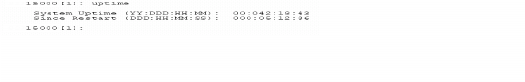
80 007-5510-002
To display the number of LUN array parity errors detected by the system, use the FAULTS
ARRAYPARITY command. The system saves the counts for each tier of all the LUNs. To clear the count
of LUN array parity errors in the system, use the FAULTS ARRAYPARITYCLEAR command.
FAULTS BUSPARITY displays the number of bus parity and data path errors detected by the system.
FAULTS BUSPARITYCLEAR clears the count of errors.
You may set a parameter (ECCSHUTDOWN) that allows the system to automatically shutdown if it
encounters an unrecoverable error. Use the FAULTS ECCSHUTDOWN=on command to enable
automatic shutdown for unrecoverable ECC errors. This is the default setting. To disable and allow the
system to continue to run in spite of unrecoverable ECC errors, use the FAULTS ECCSHUTDOWN=off.
The EXCEPTIONSHUTDOWN command parameter allows the system to automatically shutdown if it
encounters a task exception.
FAULTS EXCEPTIONSHUTDOWN=ON enables automatic shutdown for task exceptions. This is the
default setting.
The FAULTS EXCEPTIONSHUTDOWN=OFF disables automatic shutdown and allows the system to
continue to run in spite of task exceptions.
3.7.3 Displaying System Uptime
UPTIME displays the total time the system has been operational--or “uptime”(also known as Power on
Hours), as well as the total time since the last system restart. The uptime is displayed as
YY:DDD:HH:MM where YY is the number of years, DDD is the number of days, HH is the number
of hours, and MM is the number of minutes (Figure 3–60) the system has been continually in operation.
Figure 3–60 Display System Uptime
3.7.4 Saving a Comment to the Log
COMMENT <text of message> allows you to echo a message to the screen. The message is saved in the
LOG and is also sent to syslog if it is enabled. Any printable text can be entered.
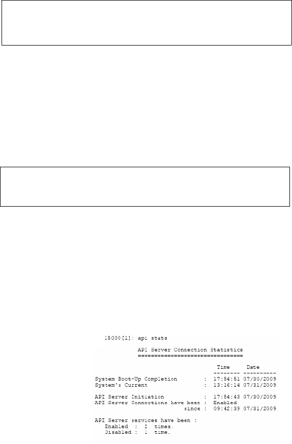
Controller Management
007-5510-002 81
3.8 Other Utilities
3.8.1 APC UPS SNMP Trap Monitor
APC_UPS displays the status of the APC UPS SNMP trap monitor (Figure 3–61).
Figure 3–61 APC UPS SNMP Trap Monitor Status
APC_UPS CLEAR_FAULTS will delete all pending APC UPS faults from the fault list. All APC UPS
events that disabled writeback caching will be cleared.
3.8.2 API Server Connections
The API command displays the current status of the API connections (Figure 3–62).
Figure 3–62 Displaying Status of API Connections
API DISABLE temporarily enables/disables the establishment of connections to the API server. When
disabled, users at remote locations will be unable to establish a new API connection until an
API ENABLE command is issued. This command only provides control over API connections during the
current power cycle.
API STATS displays the collected statistics on API connections (Figure 3–63).
API CLEARSTATS resets the collected statistics.
Figure 3–63 API Server Connection Statistics
3.8.3 Changing Baud Rate for the CLI Interface
The CONSOLE command displays the current serial console setting (Figure 3–64) of the controller.
15000 [1]: apc_ups
APC UPS SNMP trap monitor is off.
No APC UPS faults detected via SNMP trap.
15000 [1]: api
API Server connections are currently -- ENABLED--
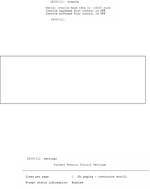
82 007-5510-002
Figure 3–64 Displaying the Serial Console Setting
CONSOLE BAUD changes the baud rate of the CONFIG port of the controller (Figure 3–65).
Figure 3–65 Changing the Baud Rate
3.8.4 CLI/Telnet Session Control Settings
You may change the CLI’s and Telnet’s various session control settings. The SETTINGS command
displays the current setting (Figure 3–66).
Figure 3–66 Current Session Control Settings
SETTINGS DEFAULTS resets all the CLI and Telnet session control settings to their default values.
SETTINGS LINES=<number of lines> sets the number of lines displayed at a time in a page of screen
information. Pages provide a way to control the amount of information displayed to the user at one time.
You will be prompted to either press a specified key in order to scroll from one page to the next, or (in
certain circumstances), to terminate the display. Valid range is 0 to 512 lines, where 0 indicates that no
paging is to be performed on the output information. Default setting is 0.
SETTINGS PROMPTINFO=ON enables extra status information in the CLI prompt. OFF disables extra
status information in the CLI prompt. When enabled, the CLI prompt indicates whether the system is
booting (BOOTING), failed (FAILED) or waiting for a restart (RESTART NEEDED). ON is the default.
3.8.5 Disk Diagnostics
The DISK DIAG=tc command performs a series of diagnostics tests on the specified disk. The disk is
specified by its physical: tier (t) in the range <1..125>, and channel (c) in the range <ABCDEFGHPS>.
15000 [1]: console baud
Select the new serial console baud rate from choices below:
1 - 9600
2 - 19200
3 - 38400
4 - 57600
5 - 115200 <- Current setting
e - escape out of this command
Enter selection:
Controller Management
007-5510-002 83
3.8.6 Disk Reassignment and Miscellaneous Disk Commands
The DISK REASSIGN=tc 0xh command allows for the reassigning of defective logical blocks on a disk
to an area of the disk reserved for this purpose. The disk is specified by its: tier (t) in the range <1..125>,
and channel (c) in the range <ABCDEFGHPS> 0xh is the hexadecimal value of the LBA (Logical Block
Address) to be reassigned.
The DISK LLFORMAT=tc command allows the user to perform a low level format of a disk drive. The
disk is specified by its: tier (t) in the range <1..125>, and channel (c) in the range <ABCDEFGHPS>.
The DISK AUTOREASSIGN=ON command is the default setting. When enabled bad blocks are
reassigned when a medium error occurs on a healthy tier, the DISK AUTOREASSIGN=OFF command
disables this feature and bad blocks are NOT reassigned when a medium error occurs on a healthy tier.
The DISK MAXCMDS=x command sets the maximum command queue depth to a tier of disks in the
range of 1 to 32 commands per tier. The default is 32 commands.
3.8.7 SPARE Commands
Use the SPARE commands to display information about the spare disks in the system or to change the
configuration settings for background diagnostics in the system. The information displayed pertains to
the current spare configuration settings as well as task status.
The SPARE CLI commands are for background diagnostics. The intent of these commands is to test
otherwise idle spare disks at least one (1) time per month to validate that they are continuing to function
properly, and are truly available to be swapped in as a replacement disk. It is testing of the “hot” spares.
They are intended to run in the background and SPARE operations are always at lower priority than any
other kind of I/O in the system.
The SPARE INFO=tc command displays the information and status about a specific spare disk in the
system. The disk is specified by its physical tier and channel locations, “tc.” The “t” indicates the tier
in the range <1..125>, and the 'c' indicates the channel in the range <ABCDEFGHPS>.
The SPARE CLEAN=tc command erases any previous test data stored on the disk indicated. The disk
is specified by its physical tier and channel locations, “tc.” The “t” indicates the tier in the range
<1..125>, and the 'c' indicates the channel in the range <ABCDEFGHPS>.
The SPARE COVERAGE=x command sets the spare diagnostic coverage of the blocks being tested as
a percent of the total number of blocks available for test. Note that increasing the coverage to higher
numbers means that more blocks on the disk will be tested for better coverage, but it also will take a
longer time for the test to complete. This parameter can be tuned to provide an optimal test time for a
single disk in the system such that all spares are tested in a reasonable amount of time. The parameter
is limited to a discrete set of values. The valid parameters for “x” are [1, 5, 10, 20, 40, 80, 100] Percent.
Default is 1 Percent.
The SPARE EXTENT=x command sets the spare diagnostic extent in Mbytes. The diagnostic extent
determines how much data can be tested before the test must sleep. This parameter slows down the test
operations so they will not affect the performance of the system. Increasing the extent will allow more
data to be tested in a single pass. Any changes applied to extent will affect tests in progress as well as
future testing. The valid range for 'x' is 1..32 Mbytes. Default is 8 Mbytes.
The SPARE DELAY=x command sets the system spare diagnostics delay. The test delay determines
how long a test operation will pause after it reaches the test extent. This parameter slows down the spare
84 007-5510-002
test so it will not affect the performance of the system. Any changes applied to delay will affect tests
in progress as well as future testing. This system spare diagnostic delay value is given in 100 millisecond
increments. The valid range for 'x' is 0..100. The default is 0.
The SPARE PATTERN=x command sets the system spare diagnostics pattern. The test pattern
determines the pattern written to the disks during the test. The system supports the following patterns:
• UNIQUE Includes unique information including timestamp
• AA 0xAA is written to each byte
• 55 0x55 is written to each byte
• FF 0xFF is written to each byte
• 00 0x00 is written to each byte
• COUNTUP A pattern of counting up is written to each byte
• COUNTDOWN A pattern of counting down is written to each byte
The default is UNIQUE. Note that the tests in progress are not affected by this parameter setting.
Changing the pattern only applies to tests started after the parameter was modified.
The SPARE START command starts the spare diagnostics task if it is not running. Note that this will start
diagnostics on both units in a dual system, as this is a system parameter.
The SPARE STOP command aborts any ongoing diagnostic operations. Note that this command will
stop them and then the task will be idle until the SPARE RESTART command is executed. Note that
this will stop diagnostics on both units in a dual system as this is a system parameter.
The SPARE PAUSE command pauses but does not stop any ongoing diagnostic operation, only on the
unit from which the command is run. If a test is being run from the other unit in a dual, the pause
command will NOT affect that test.
The SPARE RESUME command releases any paused diagnostic operations and allows them to continue
only on the unit from which the command is run. If a test has been paused on the other unit in a couplet,
the SPARE RESUME command will NOT affect that test.
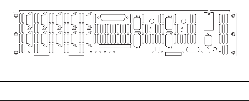
Troubleshooting
007-5510-002 85
Chapter 4
Controller Remote Management and
Troubleshooting
4.1 Remote Management of the Controller
The controller can be managed locally through the RS-232 interface, or remotely via Telnet. The
Administrative Utility is the same regardless of the management interface (RS-232 or Telnet).
The controller supports SNMP and allows the system to be remotely monitored.
4.1.1 Network Connection
Connect the Telnet port on the back of the controller to your Ethernet network (Figure 4–1). Then set the
IP addresses, login names, and passwords as described below.
Figure 4–1 Telnet Port on the Controller
NOTE :
Currently, the controller does not support network configuration protocols such as DHCP or
BOOTP.
4.1.2 Network Interface Set Up
For first time set up, you will need to connect to the CLI (RS-232) port in order to change the IP address
and/or network settings.
To set up the network interface:
1. Use the NETWORK command to display the current settings (Figure 4–2).
2. Change the controller’s IP address for your network environment: network IP=<new IP address>.
3. Change the netmask of the controller (if needed): network netmask=<new netmask>.
4. Enable the Telnet capability (if needed): network telnet=ON.
P
S
PS
G
H
GH
A
B
AB
E
F
EF
C
D
CD
DISK CHANNELS
AC
FAIL
SYSTEM
STATUS
CTRL
STATUS
TEMP
STATUS
DISK
STATUS
DC
STATUS
FAN
STATUS
TEST
STATUS
ACT
HOST 1/2
CLI
HOST 1
HOST 2
1
2
STATUS
ACT
HOST 3/4
CLI
HOST 3
HOST 4
3
4
1/2
TEST PLACE PIN HERE
LINK
ACT MUTE
AC
FAIL
ACT
LINK
ACT
LINK
TELNET
ALARM
SILENCE
CLI
COM
LINK
Telnet port
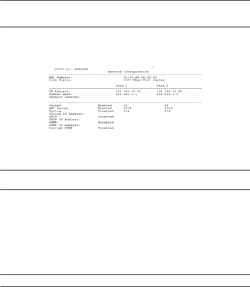
86 007-5510-002
NOTE :
Telnet connections are clear text. If Telnet connections are used, you may expose controller
passwords to third parties. For higher security, we recommend that you disengage Telnet access if it is
not required.
5. Decide whether the SNMP functionality should be enabled.
To enable or disable SNMP, use the appropriate version of the command network SNMP=on|off.
Figure 4–2 Current Network Configuration Screen
NOTE :
If you are using an external system console option like Telnet, the SNMP function should
be enabled.
6. If the SNMP function is enabled, enter the IP address of the computer to be used to monitor the
SNMP traps:
network trapip=<computer’s IP address>
7. Decide whether the Syslog capability should be enabled. To enable (ON) or disable (OFF) the
Syslog, enter:
network syslog=on|off
NOTE :
The SGI default is the Syslog capability enabled.
8. If the SYSLOG function is enabled, enter the destination IP address for the Syslog packets:
network SYSLOGIP=<destination IP address>
Ensure your destination computer supports the SYSLOG feature. For example, on UNIX systems,
the SYSLOG application must be properly installed and running.
9. The default destination port number for Syslog packets is 514. To change it, enter:
network SYSLOGPORT=<port number>
10. Set up the routing table. This table describes how the controller communicates with the hosts on
other networks. Use the ROUTE command to display the current settings (Figure 4–3).

Troubleshooting
007-5510-002 87
-ROUTE GATEWAY=<aaa.bbb.ccc.ddd> sets the current gateway in the network routing table
to the specified Internet address.
-ROUTE DEL=<aaa.bbb.ccc.ddd> GATEWAY=<aaa.bbb.ccc.ddd> deletes gateways from
the routing table.
-ROUTE ADD=<aaa.bbb.ccc.ddd> GATEWAY=<aaa.bbb.ccc.ddd> adds new gateways to
the table.
- If you have couplet controller, connect to (or Telnet to if this is not the initial set up) and log
into the other controller. Repeat the appropriate steps to set its network parameters.
Figure 4–3 Current Controller Routing Table
11. On boot up, verify the network connections, enter NETWORK PING=<IP address of a network
system>.
a) Ping a host on the same subnet as the controller.
b) Ping another host on a different subnet.
12. Make sure your firewall is running (which will block traffic and keep hosts from talking to each
other), ensure it is set up to allow the controller to pass information on Port 23 (for Telnet),
Port 161 (for SNMP), and Port 162 (for SNMP traps).
4.1.3 Login Names and Passwords
The controller’s two levels of security, administrative and general purpose user access, also applies to
remote management. If you login as an administrator, you can access all the management and
administrative functions. You can obtain status information and make changes to the system
configuration. At the user access level, you are only allowed to view the status and configuration
information of the system.
The login names and passwords can be changed using the PASSWORD command, via RS-232 or Telnet.
By default, the administrator name is admin and its password is password. Similarly, the default user
name is user and its password is password. If a user forgets the password, entering PASSWORD
DEFAULTS while logged in as “admin” will restore all passwords and user names to the default values.
Only one Telnet session is permitted at a time. Once a Telnet session is initiated, the RS-232 console
switches to a CLI sub-shell. For more information, see 3.6 ”Remote Login Management” beginning on
page 76. The Telnet client should be using port 23 and have its local echoing function disabled.
Gateway NONE
Permanent S2A Routing Table
15000 [1]: route
destination gateway
----------------------------
0.0.0.0 191.9.161.222
----------------------------
ROUTE NET TABLE
destination gateway
-----------------------------------------------------------------
0.0.0.0 191.9.161.222
-----------------------------------------------------------------
Current 15000 Routing Table
flags
3
Refcnt
0
Use
0
Interface
fei0
160.100.0.0 191.9.161.222 3
0
3 fei0
191.9.0.0 191.9.160.208 101
0
0 fei0
ROUTE HOST TABLE
destination gateway
-----------------------------------------------------------------
127.0.0.1 127.0.0.1
flags
5
Refcnt
0
Use
0
Interface
lo0
-----------------------------------------------------------------

88 007-5510-002
4.1.4 SNMP Set Up on Host Computer
The following procedure explains how to set up the host computer to monitor the controller’s events
(SNMP traps).
NOTE :
It is not possible to configure the controller through SNMP.
Refer to Section 4.1.2 in this guide for information regarding network and SNMP configuration on the
controller. Contact SGI to obtain the Management Information Base (MIB) files for the controller.
1. Ensure the host computer, which will receive the traps, has an SNMP browser (such as HP
OpenView) properly installed and configured. Refer to your browser’s documentation for
instructions on how to load the MIB files.
2. Set up the host computer to listen to Ports 161 and 162.
3. Load the following controller MIB. Note these MIB files:
-sdd.mib
- sdd_trap.mib
NOTE :
When loading the controller MIB, sdd_trap.mib must be loaded last
.
4. Start a query. You should be able to see various controller information such as tempLevel,
powerNumber, fanNumber, powerTable, tierNumber, and tierTable.
5. To verify that the SNMP function has been set up correctly:
a)Unplug one of the power supplies.
b)Check that a power failure message appears in your SNMP browser.
4.1.4.1 Controller Implementation of SNMP
InfiniteStorage 15000 MIB (The InfiniteStorage 15000 MIB is read only.)
• Temperature status {normal, warning, critical}
• Fan Status ¥1{healthy, failure}
• Power Supply Status ¥4{healthy, failure}
• Tier Status ¥125
Disk A Status {healthy, failure, missing}
Disk B Status {healthy, failure, missing}
Disk C Status {healthy, failure, missing}
Disk D Status {healthy, failure, missing}
Disk E Status {healthy, failure, missing}
Disk F Status {healthy, failure, missing}
Disk G Status {healthy, failure, missing}
Disk H Status {healthy, failure, missing}
Disk P Status {healthy, failure, missing}
Disk S Status {healthy, failure, missing}
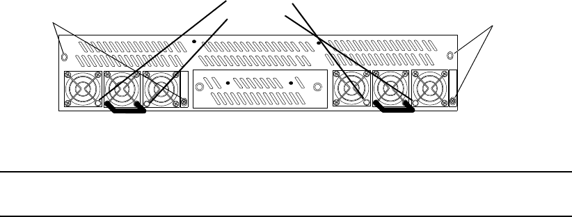
Troubleshooting
007-5510-002 89
4.1.4.2 Traps
• Generic Traps
- coldStart (occurs when the controller is restarted)
• Enterprise Specific Traps
- Any changes in controller MIB.
If any variable in the controller MIB changes, a trap will be sent. For example, when a power
supply fails or is replaced, a trap is sent. Trap includes ASCII string declaring new status of
15000 element.
- 15000 status alerts.
Trap includes ASCII string declaring the controller as failed or healed.
4.2 Troubleshooting the Controller
This section details how to perform error recovery on the controller.
To display a list of all current controller system and drive enclosure faults, enter: faults
4.2.1 Component Failure Recovery
The controller contains redundant and hot-swappable fans and power supply units. A single component
failure, therefore, will not shut down the system. However, in the unlikely event of component failure,
you can replace the failed component while the controller is running. The replaced component will
automatically be returned to service once the component has been installed and booted up.
4.2.1.1 Power Supply Failure
A power supply failure message will be displayed on your console if a power supply fails. The status
LED on the power supply module will turn off (Figure 4–4).
Figure 4–4 Power Modules - Front View
NOTE :
Make sure you have the replacement power supply available before removing the failed
module.
1. Remove the cover panel (if the panel is installed).
2. Locate the failed power supply module (indicated by an off Status LED).
3. Turn off module’s power switch (found on back of unit).
Thumbscrews Status LEDs Thumbscrews
AC Present LED
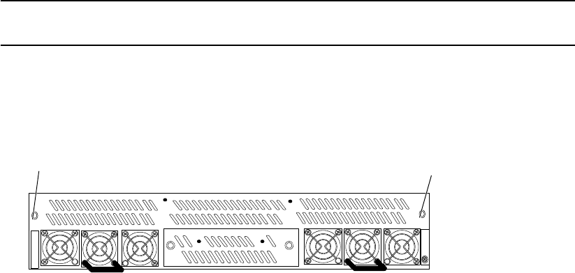
90 007-5510-002
4. Remove the module’s thumbscrews, then slide the module out of the bay.
5. Slide the module into the bay making sure it is fully inserted. Install the two thumbscrews to secure
it.
6. Turn on the power switch. Check that the Status LED is green, indicating that the module is
operating normally.
7. Replace the cover panel (if necessary).
4.2.1.2 Fan Failure
A fan failure error message will display on your console if the fan module fails. Follow these steps to
replace the module.
NOTE :
The controller should not be operated without the fan module for more than 15 seconds. Make
sure you have the replacement fan unit available before removing the failed fan unit.
1. If a cover panel has been installed, take it off by removing its two thumbscrews.
2. Remove the two thumbscrews from the fan module (Figure 4–5).
3. Slide the module out of its bay.
Figure 4–5 Fan Module
4. Slide the new module into the bay, making sure it is fully inserted.
5. Install the thumbscrews to secure it.
6. Replace the cover panel (if necessary).
4.2.2 Recovering from Drive Failures
When a drive failure occurs on the controller, the tier containing that drive will begin operating in
degraded mode. This means that the tier will continue to handle I/O commands from the host, but there
will be no redundancy to protect against additional drive failures on the same tier. If another disk drive
fails on the same tier before the data on the first drive is rebuilt (to a replacement disk or hot spare), the
tier will go offline.
If one disk in a tier fails, the data or parity information on the failed disk will be reconstructed from the
parity disk and data disks of that tier. An entire channel may fail without data loss.
It is recommended that the controller’s Automatic Disk Rebuild function be enabled at all times (TIER
AUTOREBUILD=ON).
Thumbscrew
Thumbscrew

Troubleshooting
007-5510-002 91
NOTE :
If more than one disk is failed in a single tier, only the first disk to fail will be replaced by the
spare disk. Any disks which fail after the first in each tier will not be reconstructed using a
hot spare.
4.2.2.1 Single Drive Failures
A single drive failure in any tier does not result in the data loss. The LUN(s) on that tier will continue
to operate in degraded mode. If a spare drive is available, the controller will automatically rebuild the
data on the spare drive if “autorebuild” is enabled. System operation is not affected while recovery is
taking place.
When a drive failure occurs, the controller displays an error message on your console, indicating which
drive has failed and which spare drive (if available) is replacing the failed drive. If your drive enclosure
is on the SGI official controller compatibility list, the Fault LED on the failed drive will turn amber.
The error is also written to the event log. The controller will rebuild the drive automatically once it finds
a suitable spare drive. You may monitor the rebuild progress or change the rebuild rate to match the user
load. To obtain additional information, use the TIER or LOG command.
TIER displays the status of the disks. The failed drive is denoted by an “r” .
If a Rebuild is taking place, the percentage of completion is also displayed. Figure 4–6 illustrates a
system that has a failed drive on Tier 2, Channel D and it is being rebuilt.
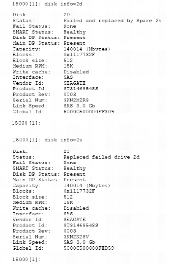
92 007-5510-002
DISK INFO will indicate what spare drive is replacing the failed drive (Figure 4–6).
Figure 4–6 Obtaining Disk Information
4.2.2.2 Returning the System to a Fault-Tolerant State
When you find a failed drive on a tier, replace it as soon as possible so that the tier can return to its optimal
state. If you replace the failed drive while a rebuild is taking place, the system will finish rebuilding data
on the spare drive first. When a rebuild is complete and the failed drive has been replaced, the system
will automatically copy the data from the spare drive to the new drive, and return the spare drive to its
standby state. The tier is then fully restored.
If no suitable spare drive exists when a drive fails, replace the failed drive as soon as possible. Once the
replacement drive is inserted and verified by the system, a rebuild will start automatically if Autorebuild
is ON. If not, initiate a rebuild by doing the following:
1. Enter: diskscan
The system checks each channel and looks for newly inserted drive(s).
2. Enter: disk rebuild=<tier><channel>.
This command initiates a disk build by tier and channel.
4.2.2.3 Manually Replacing a Failed Disk with Spare Disk
You may manually replace a specified failed disk with a spare disk using DISK
REPLACE=<tier><channel>. A Replace operation is used to temporarily replace a failed disk with a
healthy spare disk. The operation can take several hours to complete depending on the size of the disk
and speed of the replace operation. The speed of the replace operation can be adjusted with the DELAY
and EXTENT parameters. (See “Resources Allocation” on page 66.)
Troubleshooting
007-5510-002 93
4.2.2.4 Changing the Rate of Rebuild
The commands TIER DELAY and TIER EXTENT control the percentage of processor time allocated to
rebuild compared to I/O handling. Rebuild is done in steps. DELAY will control the amount of wait time
before rebuilding the next chunk of data. EXTENT determines the size of data used to rebuild.
To increase the rate of rebuild, reduce the DELAY value. (See “Resources Allocation” on page 66.) We
recommend that you use the default DELAY and EXTENT settings unless you have a specific need to
change them.
4.2.2.5 Interrupting the Rebuild Operation
To abort the rebuild, enter tier stop to stop all current rebuild operations.
4.2.2.6 Multiple Drive and Channel Failures
If multiple drives on the same drive channel fail simultaneously, the problem may be a channel failure
rather than a series of drive failures. For example, if drives 1D, 2D, and 3D fail at the same time, the
problem may be in Channel D rather than in the drives. If the drives fail as the result of a channel failure,
data on the drives may not be lost. Any single channel failure can be recovered.
Before you replace any drives:
1. Use the TIER command to check the current disk status and see if the drives failed are all on the
same channel.
2. Use the DISK command to check the status of the channel.
The Recovery steps are:
1. Contact SGI technical support to determine the cause of error and what steps may need to be taken
to recover form the error.
2. Isolate the cause of channel failure (for example, loose cable connections).
3. Rebuild all the drives on that channel individually by issuing the command:
disk rebuild=<tier><channel>
For example, disk rebuild=1d, disk rebuild=2d, disk rebuild=3d.
Several rebuild operations are processed at the same time. The other rebuild jobs are queued up and
processed in the same order as they were entered.

94 007-5510-002
4.2.3 Component Failure on Enclosures
The controller implements the SCSI Enclosure Services (SES) protocol to communicate with its drive
enclosures. If your enclosures provides SES communications, then enclosure status information of the ,
including power supply, fan, and presence of drive, will be obtained and evaluated. If a change in status
is found, an SES message is displayed on your console (Figure 4–7).
Figure 4–7 Example of SES Message
If your enclosures provide redundant SES communication paths, the message will be reported twice.
“EncID” is the Enclosure Identifier of the enclosure that reported the failure. The last four digits of the
WWN is the last four digits of the enclosure’s serial number.
EncID: 50001FF1:3E081000 Power Supply 1: OK
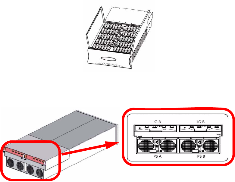
Drive Enclosure
007-5510-002 95
Chapter 5
Drive Enclosure System
5.1 The SGI InfiniteStorage 15000 Drive Enclosure
The SGI InfiniteStorage 15000 drive enclosure storage system is an ultra dense 4U 60 disk drive
enclosure. Figure 5–1 and Figure 5–2 show front and rear views of a drive enclosure, respectively.
Module and major components and their locations are shown in Figure 5–3.
Figure 5–1 The Drive Enclosure System - front open view
Figure 5–2 The Drive Enclosure System - rear isometric and rear views
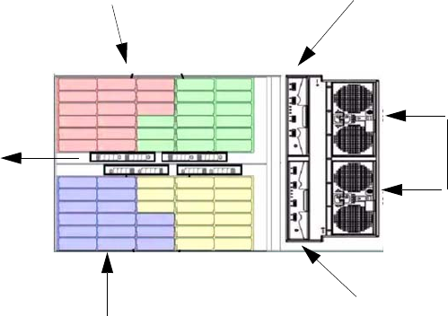
96 007-5510-002
5.2 Enclosure Core Product
The drive enclosure design concept is based on a subsystem together with a set of plug-in modules and
(as supplied) comprises:
•Enclosure Chassis with integral Front Panel Drive Status Indicator (Figure 5–9).
• Two (2) 1865W Power Cooling (PCM) plug-in modules (Figure 5–4).
• Two (2) plug-in Input/Output (I/O) modules (Figure 5–5).
• A midplane separates the front and back of the chassis and provides the interconnect system
between the PCMs, I/O modules, and the baseboard.
• Up to 60 top loadable hard disk drives (HDDs) in a 5x12 matrix.
• SAS and SATA drive intermix allowed.
The InfiniteStorage 15000 supports both SATA and SAS interface drives. SATA and SAS interface
drives can be mixed with a configuration. However, the mixing of SAS and SATA drives within a
tier is not recommended or supported.
• Eight (8) SAS disk expander modules (DEMs).
Figure 5–3 Drive Enclosure Module Locations
30 Drive Bays
30 Drive Bays
I/O-B
I/O-A
PCMs
8 DEMs
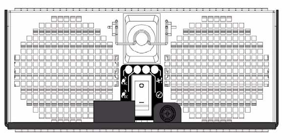
Drive Enclosure
007-5510-002 97
5.2.1 Enclosure Chassis
The chassis assembly contains 60 drive bays at the front, each of which accommodates a plug-in drive
carrier module. The 60 drive bays are arranged in five rows of twelve drives (5x12). At the rear, the
chassis assembly contains two (2) PCMs and two (2) I/O modules.
The chassis is fitted with 19-inch rack mounting features which enables it to be fitted to four (4) 19-inch
racks and uses four (4) EIA units of rack space.
5.3 The Plug-in Modules
A drive enclosure requires the following modules for normal operation:
• Power Cooling Module (PCM)
• Input/Output Module (I/O)
• Drive Carrier Module
• Drive Expander Module (DEM)
5.3.1 Power Cooling Module (PCM)
Two (2) auto ranging AC 1865W Power Cooling modules (Figure 5–4) are supplied already mounted in
the rear of the enclosure as part of the subsystem core product.
.
The drive enclosure must always be operated with two Power Cooling Modules fitted (2 PCMs).
Module replacement should only take a few minutes to perform but must be completed within 10
minutes from removal of the failed module. Four (4) LEDs mounted on the PCM (Table 5–1) indicate
the status of the PCM and the fans. PCM voltage operating ranges are nominally 200V to 240V AC.
.
Figure 5–4 Power Cooling Module (1)
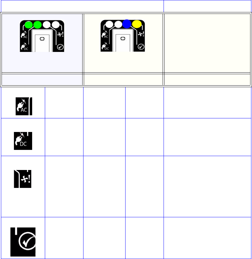
98 007-5510-002
5.3.2 Input/Output (I/O) Module
The drive enclosure storage subsystem includes an enclosure with rear facing bays which house two (2)
I/O modules (Figure 5–5). Processors housed on the I/O modules provide enclosure management and
interface to devices on the Backplane, PCM, and Display Panel in order to monitor internal functions.
The plug-in I/O modules have been designed for integration into a drive enclosure storage subsystem,
providing external SAS cable interfacing with up to 60 SAS or SATA disk drives.
Table 5–1 PCM LEDs
PCM LEDs
Normal Operation LEDs Faults LEDs Enclosure Audible Alarm
GREEN AC Input
FAILURE off
Off
GREEN DC Output
FAILURE
off
Off
OFF Fan Fault /
Power Supply
Fault
AMBER
Off
OFF ID BLUE
Off
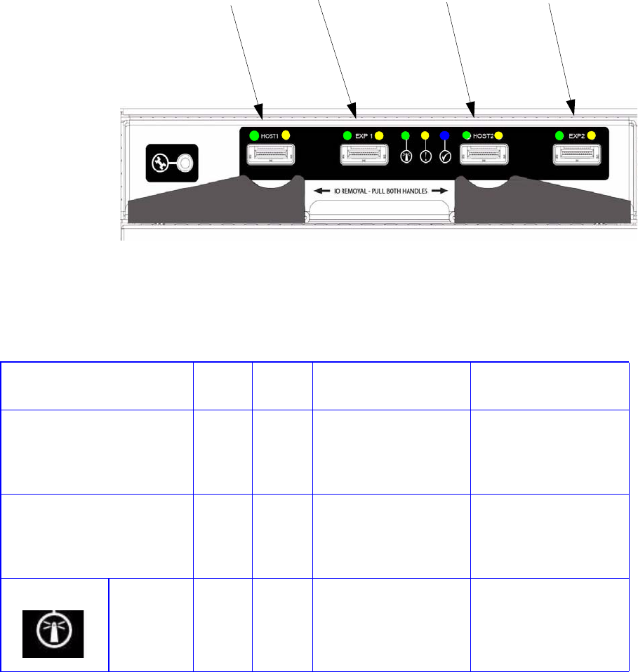
Drive Enclosure
007-5510-002 99
ITable 5–2 defines the LED indicators incorporated on the I/O module.
Figure 5–5 I/O Module
Host Port 1 Expansion Port 1 Host Port 2 Expansion Port 2
Table 5–2 I/O Module LEDs
LED Color STATU
S
Definition Enclosure Audible
Alarm
Host Port 1
Expansion Port 1
Host Port 2
Expansion Port 2
Green ON
OFF
•Incoming signal is
GOOD
•No connection or
incorrect connection
•Off
Host Port 1
Expansion Port 1
Host Port 2
Expansion Port 2
Amber ON
OFF
•Fault
•No faults
•Off
I/O Module
OK
Green ON
OFF
•properly booted and
functioning correctly
internal fault
•Off
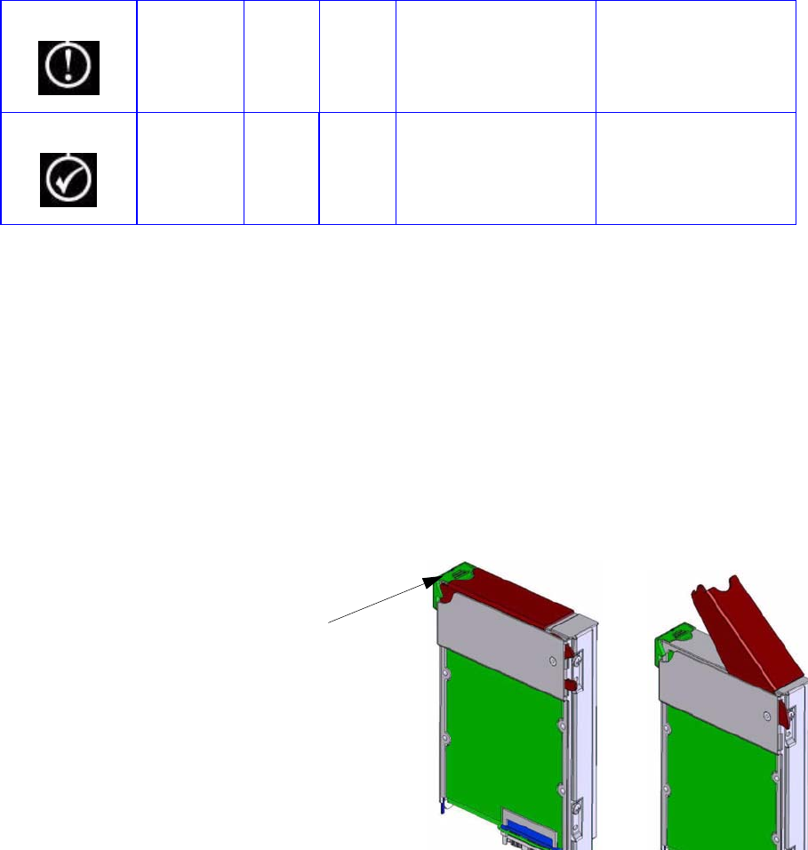
100 007-5510-002
5.3.3 Drive Carrier Module and Status Indicator
The Drive Carrier Module comprises a hard disk mounted in a carrier (Figure 5–6). Each drive bay can
house a single Low Profile 1.0 inch high, 3.5 inch form factor disk drive in its carrier.
The handle provides the following functions:
• Camming of carrier into and out of drive bays.
• Positive 'spring loading' of the drive/baseplane connector.
• The handle assembly also incorporates a Drive Status LED (Figure 5–6).
Note The enclosure system design allows for drive bays to be left empty without the need for fitting dummy
drive carriers.
5.3.4 DEM Card
The drive enclosure contains eight (8) top-loadable DEMs. The DEMs (Figure 5–7) provide the SAS
connectivity between the I/O module and the HDDs located within the enclosure.
I/O Module
Fault
Amber OFF
ON
•No Faults present
I/O Fault
•Off
I/O Module
Identity
Blue ON
OFF
•Receiving SES
Command
Not receiving SES
Command
•Off
Table 5–2 I/O Module LEDs
Figure 5–6 Drive Carrier Module: Closed and Opened
LED
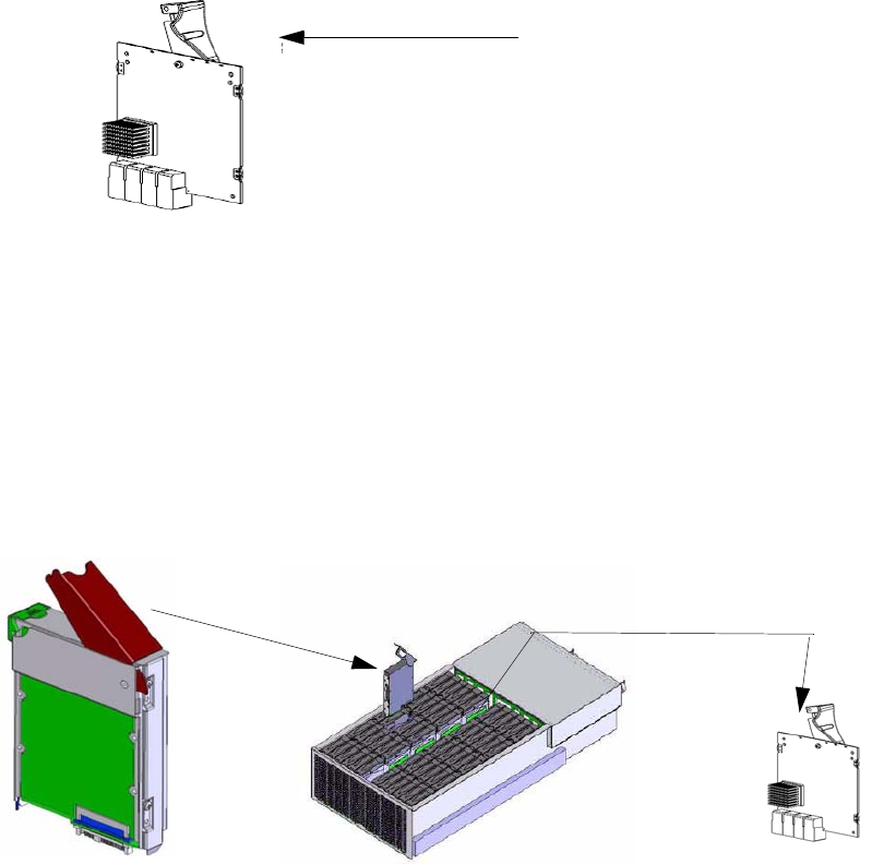
Drive Enclosure
007-5510-002 101
Note The DEM is a serviceable PCB which may be replaced by trained personnel.
Each DEM connects to a single port of the HDD based on the location within the enclosure within which
it is installed (Figure 5–8). Each provides power control signals to each drive slot. It controls HDD
identify/service LEDs and monitors the status from partner DEM. Each pair set DEM supports 15 drives;
there are 8 DEMs in a fully configured system.
5.4 Indicators
The drive enclosure has both FRU and status LEDs to indicate the state of various components within
the enclosure. Each FRU has a visible BLUE identity LED. Each FRU, except the HDD, has a visible
AMBER LED which indicates a fault.
Note In some components, the failure LED is internal to the enclosure and visible only when the cover is open.
The state of each LED within the enclosure is available through the in-band SES functionality at all
times. The host can manually set the state of each LED through an in-band SES page.
5.4.1 Front Panel Drive Activity Indicators
The Front Panel Drive Activity Indicators show the aggregated status of all the modules. This panel and
its associated LEDs are shown in Figure 5–9. Drive activity LEDs flash during data I/O when transition
Figure 5–7 DEM
Locking Mechanism
Figure 5–8 Drive Carrier and DEM Locations
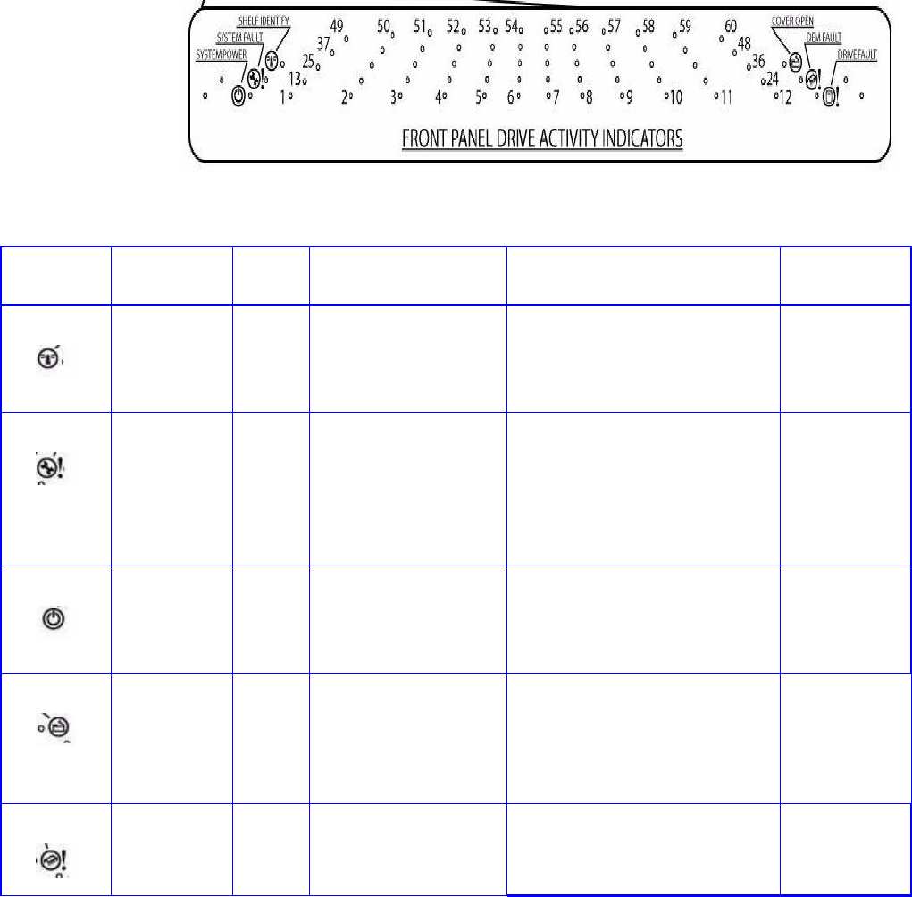
102 007-5510-002
cards are fitted to drives. These LEDs indicate drive presence. The Front Display Panel LEDs are
defined in Table 5–3.
Figure 5–9 Front Panel Drive Activity Indicators Panel
Table 5–3 Display Panel LEDs
ICON LABEL COLOR Definition Normal Behavior Enclosure
Audible Alarm
Shelf Identify BLUE enclosure Identity ON-SES is sending an identity
command.
OFF-SES is NOT sending an
identity command
Off
System Fault AMBER Enclosure Fault ON-one or more components within
enclosure have failed. A service
action is required. Exact failed
component has its own amber fault
LED lit.
OFF-no detectable faults
Off
System Power GREEN Enclosure Powered ON ON - DC power is present
OFF - DC power is NOT present
LED does NOT flash under normal
operating conditions.
Off
Cover Open AMBER Enclosure cover is open OFF-both cover pieces securely
closed and latched in place.
ON-either of the cover pieces is
NOT securely closed and latched in
place
Off
DEM Fault AMBER DEM fault OFF-all DEMs operating correctly.
ON-at least one DEM has failed;
service action required
Off

Drive Enclosure
007-5510-002 103
.
Drive Fault AMBER Drive fault ON-one or more HDDs are faulted.
SES must determine exact HDD.
OFF-no detectable drive faults
Off
Individually
numbered
HDDs GREEN HDD activity ON-indicates HDD activity
OFF-no HDD activity
Off
Table 5–3 Display Panel LEDs
ICON LABEL COLOR Definition Normal Behavior Enclosure
Audible Alarm

104 007-5510-002
5.4.2 Internal Indicators
Note In some components, the failure LED is internal to the enclosure and visible only when the cover is open.
The Internal LED indicators are explained in Table 5–4.
5.4.3 Rear of Enclosure Activity Indicators
The PCMs and the I/O Modules are located on the rear of the enclosures. The LEDs on the rear of the
enclosure are explained in Table 5–5.
Table 5–4 INTERNAL LED Indicators
Description Location Color Normal Behavior Enclosure Audible
Alarm
DEM DC DEM internal to
enclosure
GREEN ON-1.2VDC regulator circuit correctly
functioning
OFF- faulty 2.1VDC regulator circuit
Off
DEM ID DEM internal to
enclosure
BLUE ON-receiving SES identity command
OFF-NOT receiving SES identity command
Off
HDD ID HDD internal to
enclosure
BLUE ON-receiving SES identity command
OFF-NOT receiving SES identity command
Off
Table 5–5 LEDs on the Rear of the Enclosure
Description Location COLOR Normal Behavior Enclosure Audible
Alarm
PCM DC ok PCM
rear of enclosure
GREEN ON-DC output of PCM within tolerances.
OFF-failed PCM
Off
PCM AC ok PCM
rear of enclosure
GREEN ON-AC input to PCM within tolerances.
OFF-failed PCM
Off
PCM Fault PCM
rear of enclosure
AMBER ON - PCM fault detected
OFF - no detected PCM faults.
Off
PCM ID PCM
rear of enclosure
BLUE ON-receiving SES identity command
OFF-NOT receiving SES identity command
Off
I/O Module ok I/O Module
rear of enclosure
GREEN ON-properly booted and functioning
correctly.
OFF-I/O Module internal fault
Off
I/O Fault I/O Module
rear of enclosure
AMBER ON - I/O module fault detected
OFF - no detected I/O module faults.
Off
I/O Module ID I/O Module
rear of enclosure
BLUE ON-receiving SES identity command
OFF-NOT receiving SES identity command
Off

Drive Enclosure
007-5510-002 105
5.5 Visible and Audible Alarms
The functional modules have associated status LEDs. The Display Panel (Table 5–3) shows a
consolidated status for all modules:
• Constant GREEN or BLUE LEDs indicate good or positive indication.
• Constant AMBER LEDs indicate that there is a fault present within that module.
Note The Display Panel also incorporates an Audible Alarm. The only time the enclosure will sound an alarm
is when the top cover of the enclosure is opened. There is a warning beep when the cover is first opened.
If the top cover is left open for more than five minutes, the audible alarm will be continuous.
Warning The Display Panel is an integral part of the enclosure chassis assembly and is not field
replaceable.
5.6 Drive Enclosure Technical Specification
5.6.1 Dimensions
SAS Link I/O Module
rear of enclosure
GREEN ON-a valid SAS link established on at least 1
of the 4 SAS links of the 4-wide SAS port.
OFF-no SAS links
Off
SAS Link
Fault
I/O Module
rear of enclosure
AMBER ON-a detectable fault on at least 1 of the 4
SAS links of the 4-wide SAS port.
OFF-no detectable faults
Off
Table 5–5 LEDs on the Rear of the Enclosure
Description Location COLOR Normal Behavior Enclosure Audible
Alarm
Enclosure inches millimeters
Height 6.97 177
Width front 16.56 420.6
Width rear 17.56 446
Depth
front surface of bezel to end of cable management arms
42 1067
LENGTH
rack mounting surface to rear connectors surface
36 914

106 007-5510-002
5.6.2 Weight
5.6.3 AC INPUT PCM
5.6.4 DC INPUT PCM
Item Quantity per System LBS (kg) Extended Weight
Chassis
Includes
Base PCB & Midplane
18383
PCM 2 12 24
I/O Module Drives 2 4 8
60 2 120
Miscellaneous 1 5 5
Total Weight 240
Input Parameter Value
Input Voltage 190 - 264 VAC
Input Frequency 47 - 63 Hz and 400 hz
Maximum Input Current 13.1A RMS @ 190 VAC
Peak Inrush Current 50A @ 230VAC, 250
C, 5 msec max
Minimum Efficiency
measured at 30% and 50%
load and nominal line
(208 VAC)
90%
Maximum Average Output Power 1750 W
Maximum Peak Output Power, 1 second 1922W
Input Parameter Value
Input Voltage 36 - 72 VAC
Maximum Input Current TBD
Peak Inrush Current TBD
Minimum Efficiency
measured at 30% and 50%
load and nominal line
(48 DVC)
90%
Maximum Average Output Power 1750 W
Maximum Peak Output Power, 1 second 1922W
Drive Enclosure
007-5510-002 107
5.6.5 DC OUTPUT PCM
5.6.6 PCM Safety and EMC Compliance
5.6.7 Power Cord
(minimum requirements)
Note Power cord is not included in the standard drive enclosure package.
5.7 Environment
The enclosure and all of its sub-components are compliant to the European Union RoHS (Restriction of
Hazardous Substances) Directive (Directive 2002/95/EC) with no exceptions or exemptions.
Output Parameter 3.3 VDC Output 5 VDC Output 12 VDC Output
Normal Voltage 3.3 VDC 5.10 VDC 12.10 VDC
Full Load 5.0A 55.0A 120.0A
Peak Load for 1 Second 5.0A 65.0A 130.0A
Minimum Load (A) 0.0A 0.0A 0.0A
Safety Compliance UL 60950
IEC 60950
EN 60950
EMC Compliance CFR47 Part 15B Class A
EN55022
EN55024
Cord Type SV or SVT, 18 AWG minimum, 3 conductor
Plug 250V, 10A
Socket IEC 320 C-14, 250V, 15A

Drive Enclosure Installation
007-5510-002 109
Chapter 6
Drive Enclosure Installation
6.1 Introduction
Caution When connecting up the drive enclosure subsystem, use only the cables supplied.
6.2 Planning Your Installation
Before you begin installation, you should become familiar with the configuration requirements of
your drive enclosure system and the correct positions of each of the optional plug-in modules
(Table 6–1). .
Table 6–1 Drive Enclosure Configuration
Module Location
Drive Bays You can install from 1 - 60 drives in the enclosure.
In 1x mode, (connected to 10 enclosures), you can install any
number of drives in the enclosure, but every enclosure should have
the same number of drives.
In 2x mode, (connected to 5 enclosures), you must install drives in
multiples of two (2).

110 007-5510-002
6.2.1 Enclosure Bay Numbering Convention
Warning Operation of the Enclosure with ANY of the plug-in modules missing from the rear of the
enclosure will disrupt the airflow and the drives will not receive sufficient cooling. It is
ESSENTIAL that all (rear) apertures are filled before operating the unit.
The drive enclosure subsystem is housed in a 60-drive bay enclosure, arranged in four (4) groups. Each
group comprises two banks of 15 bays, that is, (as viewed from the front): 12 bays across the enclosure
by 5 bays deep. There are two numbering schemes: 1x60 and 2x30. The drive bays are numbered in
accordance with the tables shown in Figure 6–2 and Figure 6–3, when viewed from above.
Note Drive 61 is optional drive.
Power Cooling Modules (PCM) Two (2) PCMs must be fitted. Full power and cooling redundancy
is provided while a faulty module is replaced. Install the PCMs in
lower rear bays A and B.
Note: Rear bays are numbered from A and B starting from the
left when viewed from the back.
I/O Module One or two I/O modules should be Installed in the upper rear bays
A & B.
Note: If only one module is installed, it should be fitted in
Module Location A and a blank plate must be fitted
over the unused bay.
Figure 6–1 DEM Pair Locations
Table 6–1 Drive Enclosure Configuration
Module Location
Bay B
I/O
Bay A
I/O
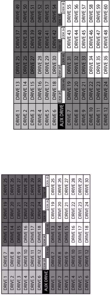
Drive Enclosure Installation
007-5510-002 111
Figure 6–2 1X60 Drive Numbering Table.
Figure 6–3 2x30 Drive Numbering Table
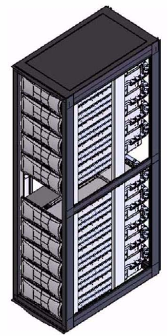
112 007-5510-002
6.3 Enclosure Installation Procedures
Important SGI InfiniteStorage 15000 drive enclosures should only be installed in SGI InfiniteStorage 15000
racks. Mounting and installing these drive enclosures in any other rack is not authorized or
supported by SGI.
Warning The drive enclosure with all its component parts installed is too heavy for a single person to
easily install into a Rack cabinet.
Caution Ensure that you have fitted and checked a suitable anti-static wrist or ankle strap and observe all
conventional ESD precautions when handling drive enclosure modules and components. Avoid contact
with Backplane components and module connectors, etc.
Note Drive enclosures are supplied and delivered populated with Backplane, Baseplane, Front Panel, DEMs,
and with PCMs installed. The Drive Carrier Modules are supplied as a separate package.
A typical rack mounting installation in shown in Figure 6–4
6.4 I/O Module Configurations
6.4.1 Controller Options
• The drive enclosure has a standard SAS JBOD IO controller, which employs a 36-port expander
with zoning. The zoning is implemented via a preset piano-switch located on the enclosure
baseboard. Host ports 1 and 2 present drives 1 through 30 and host ports 3 and 4 present drives
31 through 60. Each host port responds with drive information applicable only to the drives
presented on the respective zone and enclosure status information for the entire enclosure.
Figure 6–4 Full Rack without Controllers.
Drive Enclosure Installation
007-5510-002 113
6.5 SAS DEM
The drive enclosure contains eight (8) top-loadable DEMs. The DEMs provide the SAS connectivity
between the I/O module and the HDDs located within the enclosure. Each DEM connects to a single port
of the HDD based on the location within the enclosure in which it is installed. Each of the eight DEMs
installed in the enclosure has a unique I2C and SAS address based on a proprietary SAS address
generation scheme.
6.6 SATA Interposer Features
The drive enclosure supports an active/active SATA MUX interposer which allows simultaneous access
to the SATA HDD from both I/O modules installed in the enclosure. The MUX is implemented as a
dongle module installed in the HDD carrier assembly. Additionally, the SATA interposer allows the
power cycling of an individual HDD via SES commands.
6.7 Drive Enclosure Device Addressing
See Appendix B, “Drive Addressing”.
6.8 Grounding Checks
The product must only be connected to a power source that has a safety electrical earth connection.
Warning If more than one product is fitted in a rack, the earth connection to the rack is even more
important, because the rack will then have a high “EARTH LEAKAGE CURRENT” (“TOUCH
CURRENT”).
The earth connection to the rack must be checked before switching on, by an electrical engineer who is
qualified to the appropriate local and National standards to perform the check.
Drive Enclosure Operation
007-5510-002 115
Chapter 7
Drive Enclosure Operation
7.1 Before You Begin
Before powering up the enclosure, please ensure that all the modules are firmly seated in their correct
bays.
7.2 Power On / Power Down
Caution Do not operate the subsystem until the ambient temperature is within the specified operating range. If the
drives have been recently installed, ensure they have had time to acclimatize before operating them.
To Power On the enclosure.
• Apply AC power to the enclosure. Turn the PCMs to ON.
All LEDs on the I/O Panel should be lit (Green) when the enclosure power is activated (and the disk
drive motors should start).
Important If AC power is lost for any reason, on restoration of power the enclosure will re-start
automatically.
To power the enclosure down:
• Switch off the PCMs installed in the enclosure.
7.2.1 PCM LEDs
The PCM incorporates 4 LEDs, located above the On/Off switch. Please refer to Figure 5–4 and Table
5–2.
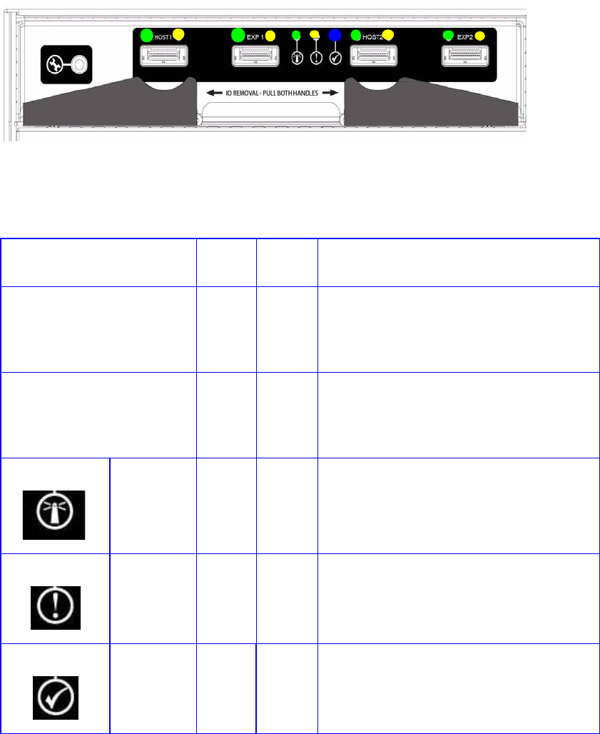
116 007-5510-002
7.2.2 I/O Panel LEDs
The I/O Panel LEDs fault and status conditions are shown in Figure 7–1.
ITable 7–1 defines the LED indicators incorporated on the I/O module.
Figure 7–1 I/O Panel LEDs
Table 7–1 I/O Module LEDs
LED Color STATU
S
Definition
Host Port 1
Expansion Port 1
Host Port 2
Expansion Port 2
Green ON
OFF
•Incoming signal is GOOD
•No connection or incorrect connection
Host Port 1
Expansion Port 1
Host Port 2
Expansion Port 2
Amber ON
OFF
•Fault
•No faults
I/O Module
OK
Green ON
OFF
•properly booted and functioning correctly
internal fault
I/O Module
Fault
Amber OFF
ON
•No Faults present
I/O Fault
I/O Module
Identity
Blue ON
OFF
•Receiving SES Command
Not receiving SES Command
Drive Enclosure Troubleshooting
007-5510-002 117
Chapter 8
Drive Enclosure Troubleshooting
8.1 Overview
The SGI InfiniteStorage15000 Drive Enclosure includes an Enclosure Services Processor and associated
monitoring and control logic to enable it to diagnose problems within the enclosure’s power, cooling,
and drive systems.
The sensors for power and cooling conditions are housed within the PCMs. Each unit is independently
monitored.
8.2 Initial Start-up Problems
8.2.1 Faulty Cords
First check that you have wired up the subsystem correctly. If:
• cords are missing or damaged,
• plugs are incorrect,
• cords are too short,
Call your supplier for a replacement.
8.2.2 Alarm Sounds On Power Up
Please refer to Section 8.4.
8.2.3 Green “Signal Good” LED on I/O Module Not Lit
Check to ensure that the cables have not been reversed during installation.
8.2.4 Computer Doesn’t Recognize the Drive Enclosure Subsystem
1Check that the SAS interface cables from the drive enclosure to the host computer, or I/O controller, are
fitted correctly.
2Check that all drive carrier modules have been correctly installed.

118 007-5510-002
3Check that there is a valid SAS signal present at the I/O connector. If there is no signal present, ensure
the cable has been properly inserted.
4Check the I/O module setup as follows:
–Ensure the I/O module has been correctly installed and all external links and cables are securely
fitted.
–Ensure the maximum cable length has not been exceeded.
8.3 LEDs
Green LEDs are always used for good or positive indication. Amber LEDs indicate there is a critical
fault present within the module. See specific LED tables for further information.
8.3.1 HDD (Hard Disk Drive)
When a HDD is faulted, Table 8–1 describes the fault LED behavior.
• Under Normal conditions, the LEDs should all be illuminated constant GREEN.
• If a problem is detected, the color of the relevant LED will change to AMBER.
8.3.2 PCM (Power Cooling Module)
The PCM LEDs are shown in Table 8–2.
• Under Normal conditions, the LEDs should all be illuminated constant GREEN
• If a problem is detected, the color of the relevant LED will change to AMBER.
8.3.3 DEM (Drive Expander Module)
The DEM fault LEDs are explained in Table 8–3.
Table 8–1 HDD LEDs
Location Color Identifier Behavior
Enclosure front Amber Enclosure fault This LED is ON with a drive fault
Enclosure front Amber Drive fault This LED is ON with a drive fault
Table 8–2 PCM LEDs
Location Color LED Identifier Behavior
FRONT Enclosure Amber Enclosure fault This LED is ON with a PCM fault.
REAR Enclosure
PCM Amber PCM fault This LED is ON with an AC input, DC output,
fan or other PCM fault.
REAR Enclosure
PCM Green AC OK This LED is ON with a DC or fan fault.
This LED is OFF with an AC input failure.
REAR Enclosure
PCM Green DC OK This LED is ON with an AC or fan fault.
This LED is OFF with an DC output failure

Drive Enclosure Troubleshooting
007-5510-002 119
• Under Normal conditions, the LEDs should all be illuminated constant GREEN
• If a problem is detected, the color of the relevant LED will change to AMBER.
8.3.4 I/O Module
The I/O fault LEDs are explained in Table 8–4.
• Under Normal conditions, the LEDs should all be illuminated constant GREEN
• If a problem is detected, the color of the relevant LED will change to AMBER.
Table 8–3 DEM LEDs
Location Color LED Identifier Behavior
FRONT Enclosure Amber Enclosure fault ON with a DEM fault.
FRONT Enclosure Amber DEM fault ON with a DEM fault.
Internal (DEM)
Enclosure Amber DEM fault ON with a DEM fault.
Internal (DEM)
Enclosure Green DC OK ON when the DC voltage regulation is
within limits.
OFF with a DC output failure.
Internal (DEM)
Enclosure Green Expander MIPS
ready
ON when the expander internal processor
is booted and operating correctly.
OFF when the expander internal
processor is NOT booted or ready.
Internal (DEM)
Enclosure BLUE DEM identify ON indicates that this DEM is being sent
an identify command by the SEP.
Table 8–4 I/O LEDs
Location Color LED Identifier Behavior
FRONT Enclosure Amber Enclosure fault ON with an I/O fault.
REAR Enclosure Green I/O OK OFF when an I/O module detectable fault
is present.
INDEPENDENT of SAS link fault condition
and stays lit during a SAS link fault.
REAR Enclosure Amber I/O fault ON when a detectable fault is present in
the I/O module.
INDEPENDENT of SAS link fault condition
and stays lit during a SAS link fault.
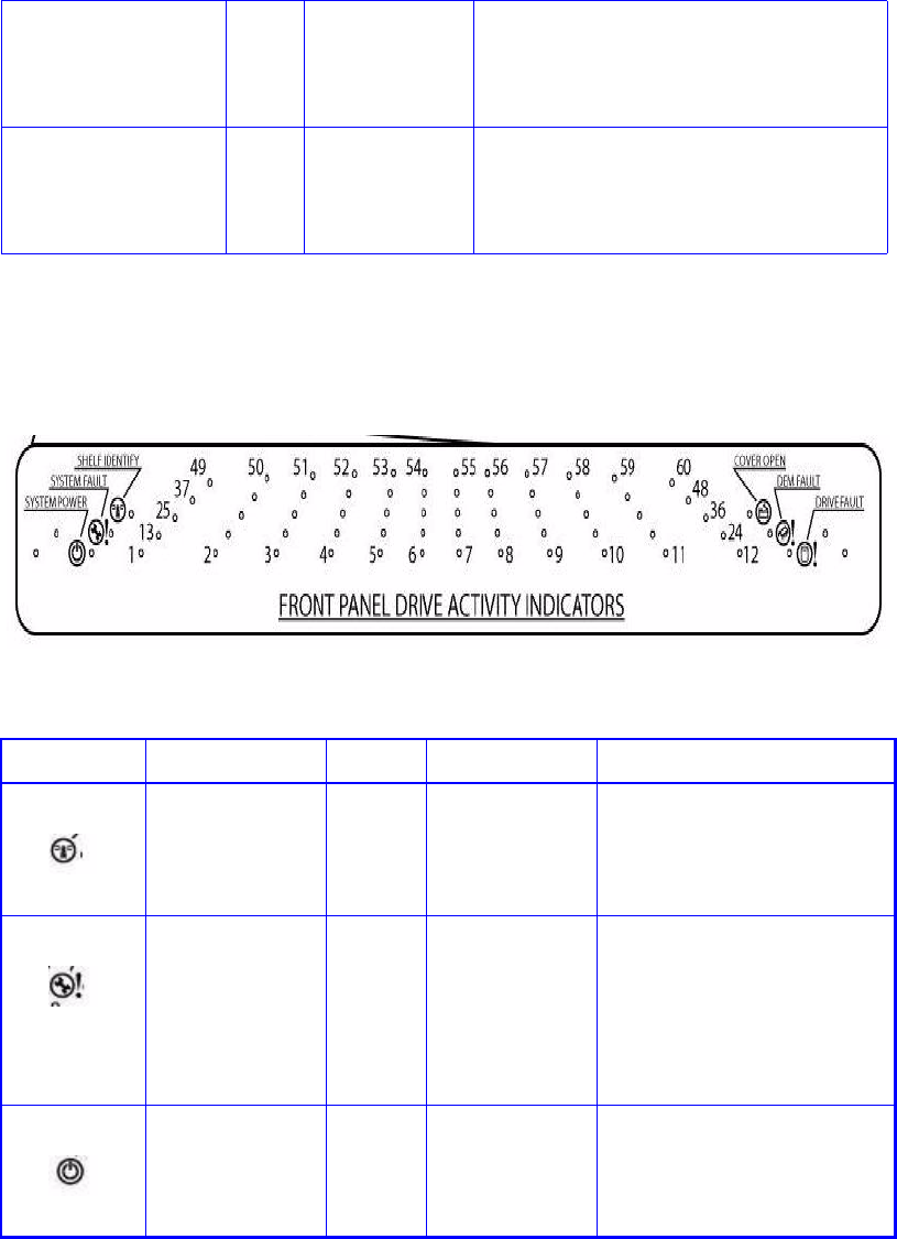
120 007-5510-002
8.3.5 Front Panel Drive Activity Indicators
The Front Panel Drive Activity Indicators show the aggregated status of all the modules. This panel and
its associated LEDs are shown in Figure 8–1. The Display Panel LEDs are defined in Table 8–5.
REAR Enclosure Green SAS Link
Activity
ON when a valid link is present on any of
the 4 links of the 4-wide port.
OFF when none of the 4 links of the 4-
wide port have a valid connection.
REAR Enclosure Amber SAS Link Fault ON when a fault is present on any of the 4
links of the 4-wide port.
OFF when none of the 4 links of the 4-
wide port have a fault.
Table 8–4 I/O LEDs
Figure 8–1 Front Panel Drive Activity Indicators Panel
Table 8–5 Display Panel LEDs
ICON LABEL COLOR Definition Normal Behavior
Shelf Identify BLUE enclosure Identity ON-SES is sending an identity
command.
OFF-SES is NOT sending an
identity command
System Fault AMBER Enclosure Fault ON-one or more components
within enclosure have failed. A
service action is required. Exact
failed component has its own
amber fault LED lit.
OFF-no detectable faults
System Power GREEN Enclosure
Powered ON
ON - DC power is present
OFF - DC power is NOT present
LED does NOT flash under
normal operating conditions.

Drive Enclosure Troubleshooting
007-5510-002 121
8.4 Audible Alarm
When the Audible Alarm sounds, use the appropriate SES CLI command.
8.4.1 Top Cover Open
The Audible Alarm sounds anytime the top cover is open. The alarm mutes automatically once the cover
is closed.
8.4.2 SES Command
The Audible Alarm can be set through SES communication. When set in this manner, the alarm remains
on until any one of the following conditions is met:
• Enclosure is power cycled.
• Alarm is turned off through SES command.
8.5 Troubleshooting
The following sections describe common problems (and possible solutions) you might encounter with
your drive enclosure system.
8.5.1 Thermal Control
The drive enclosure uses extensive thermal monitoring and takes a number of actions to ensure
component temperatures are kept low and also to minimize acoustic noise. Air flow is from the front,
over the drive section, through the midplane, through the I/O modules to rear of the enclosure.
Cover Open AMBER Enclosure cover
is open
OFF-both cover pieces securely
closed and latched in place.
ON-either of the cover pieces is
NOT securely closed and
latched in place
DEM Fault AMBER DEM fault OFF-all DEMs operating
correctly.
ON-at least one DEM has failed;
service action required
Drive Fault AMBER Drive fault ON-one or more HDDs are
faulted. SES must determine
exact HDD.
OFF-no detectable drive faults
Table 8–5 Display Panel LEDs
ICON LABEL COLOR Definition Normal Behavior

122 007-5510-002
Symptom Cause Action
If the ambient air is cool
(below 25 °C) and the fans
are observed to increase in
speed, then some restriction
on airflow may be causing
additional internal
temperature rise.
Note: This is not a fault
condition.
The first stage in the thermal
control process is for the fans
to automatically increase in
speed when a thermal
threshold is reached. This
may be caused by higher
ambient temperatures in the
local environment and may
be perfectly normal.
Note: This threshold
changes according to the
number of drives and PCMs
fitted.
1Check the installation for any
airflow restrictions at either the
front or rear of the enclosure. A
minimum gap of 25mm at the front
and 50mm at the rear is
recommended.
2Check for restrictions due to dust
build-up; clean as appropriate.
3Check for excessive re-circulation
of heated air from rear to the front.
Use in a fully enclosed rack
installation is not recommended.
4Check that all Blank modules are in
place.
5Reduce the ambient temperature.

Drive Enclosure Troubleshooting
007-5510-002 123
8.5.2 Thermal Alarm
8.5.3 Thermal Shutdown
Important An enclosure will shut down when a critical temperature threshold is exceeded in order to prevent
permanent damage to the disk drives.
8.6 Dealing with Hardware Faults
Ensure that you have obtained a replacement module of the same type before removing any faulty
module.
Warning If the drive enclosure subsystem is powered up and you remove any module, replace it
immediately. If the subsystem is used with modules or module blanks missing for more than a
few minutes, the enclosure can overheat, causing power failure and data loss. Such use will
invalidate the warranty.
• Replace a faulty drive with a drive of the same type and equal or greater capacity.
• All the supplied plug-in PCMs, electronics modules, and blank modules must be in place for the air
to flow correctly around the cabinet.
Symptom Cause Action
•Display Panel PCM/
Cooling Fault LED.
• An AMBER LED on
one or more PCMs.
• Audible Alarm
Sounding.
• Air temperature
exiting PCM above
35°C.
If the internal temperature
measured in the airflow
through the enclosure exceeds
a pre-set threshold, a thermal
alarm will sound.
1Check local ambient environment
temperature is below the upper 40°C
specification.
2Check the installation for any
airflow restrictions at either the
front or rear of the enclosure. A
minimum gap of 25mm at the front
and 50mm at the rear is
recommended.
3Check for restrictions due to dust
build-up. Clean as appropriate.
4Check for excessive re-circulation
of heated air from rear to the front.
Use in a fully enclosed rack
installation is not recommended.
5If possible, shutdown the enclosure
and investigate the problem before
continuing.

124 007-5510-002
8.7 Continuous Operation During Replacement
Depending on how the subsystem is set up, if a disk unit fails, it can normally be replaced without
interrupting the use of the system.
8.8 Replacing a Module
Warning Whenever replacing a module NEVER leave an EMPTY bay in the rear of the enclosure, obtain a
replacement before removing the problem part.
Please refer to Chapter 6, ”Drive Enclosure Installation” for information on the initial installation of the
plug-in modules in the drive enclosure.
Warning Observe all conventional ESD precautions when handling drive enclosure modules and
components. Avoid contact with Backplane components and module connectors, etc.
8.8.1 Power Cooling Modules
Warning Do not remove covers from the Power Cooling module (PCM). There is a danger of electric shock.
Return the PCM to your supplier for repair.
Warning To ensure your system has warning of a power failure please disconnect the power from the
power supply, by either the switch (where present) or by physically removing the power source,
prior to removing the PCM from the enclosure/shelf. Do not remove the faulty PCM unless you
have a replacement unit of the correct type ready for insertion. The system must not be run
without all units in place.
If a power supply unit or its fan is faulty, you must replace the whole PCM. You must not take any longer
than 5 minutes to replace this unit to prevent the enclosure from over-heating.
As there should always be two (2) PCMs installed, you can continue working while replacing the faulty
module.
To remove an AC PCM/Cooling Module- Handle Model:
Warning Do not remove the faulty PCM/Cooling module unless you have a replacement unit of the correct
type ready for insertion.
If a power supply unit or its fan is faulty, you must replace the whole PCM/Cooling module.
As there should always be two PCMs installed, you can continue working while replacing the faulty
module.
1Make sure you identify the faulty PCM correctly from the two modules installed.
2Lift latch which secures the power supply cord.
3Switch off and disconnect the power supply cord.
4Lift the PCM handle to the open position to cam the PCM out of the enclosure.
5 Grip the handle and withdraw the PCM.

Drive Enclosure Troubleshooting
007-5510-002 125
To remove an AC PCM - Thumb Screw Model:
Warning Do not remove the faulty PCM unless you have a replacement unit of the correct type ready for
insertion.
If a power supply unit or its fan is faulty, you must replace the whole PCM.
As there should always be two PCMs installed, you can continue working while replacing the faulty
module.
1Make sure you identify the faulty PCM correctly from the two modules installed.
2Lift latch which secures the power supply cord.
3Switch off and disconnect the power supply cord.
4Remove the two thumbscrews on the right and left sides of the unit.
5Firmly grip the handle on the bottom of the unit and withdraw the PCM.
To install an AC PCM - Handle Model:
6Check for damage, especially to the rear connector on the PCM.
Caution Handle the module carefully and avoid damaging the connector pins. Do not install the module if any pins
appear to be bent.
7With the PCM handle in the open position, slide the module into the enclosure.
8Cam the module home by manually closing the PCM handle. A click should be heard as the handle
latches engage.
9Connect the power supply cord to the power source, secure the latch over the cord, and switch the power
supply ON.
Note The alarm will sound until the new PCM is operating correctly.
To install an AC PCM - Thumbscrew Model:
1Check for damage, especially to the rear connector on the PCM.
Caution Handle the module carefully and avoid damaging the connector pins. Do not install the module if any pins
appear to be bent.
2Slide the module into the enclosure and push unit you hear a click as the latch is engaged.
3Secure the two thumbscrews on the left and right sides of the unit.
4Connect the power supply cord to the power source; secure latch, and switch the power supply ON.
Note The alarm will sound until the new PCM is operating correctly.
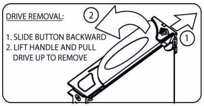
126 007-5510-002
8.8.2 I/O Module
Warning Do not remove this module unless a replacement can be immediately added. The system must not
be run without all units in place.
To remove the I/O Module:
1Release the two latches on the bottom of the unit by simply pulling each latch out and away from unit.
2Pull the latches forward to cam the module out of the enclosure.
3Grip the unit securely and withdraw the module.
To installing the I/O Module:
4With the latches in the open position, slide the EBOD module into the enclosure until the latch engages
automatically.
5Cam the module home by manually closing the latches. A click should be heard as the latch engages.
8.8.3 Replacing the Drive Carrier Module
Warning Observe all conventional ESD precautions when handling drive enclosure modules and
components. Avoid contact with backplane components and module connectors, etc.
Instructions are also clearly labeled on the inside cover of the enclosures.
Caution Drive spin down
Damage can occur to a drive if it is removed while still spinning. If possible, use the operating system to
Figure 8–2 Drive Carrier - Handle Released
Drive Enclosure Troubleshooting
007-5510-002 127
spindown the drives prior to removal. If this is not possible, we recommend that you perform All steps of
the following procedure to ensure that the drive has stopped prior to removal:
To Insert the Drive Carrier Module
1Release the carrier handle by sliding the latch backwards.
2Insert the carrier into the enclosure.
3Slide the drive carrier, gently, all the way into the enclosure.
4Cam the drive carrier home. The camming foot on the base of the carrier will engage into a slot in the
enclosure.
5When the carrier is fully home, close the handle. You should hear a click as the latch engages and holds
the handle closed.
6Close the enclosure.
8.9 Replacing the DEM
Important The DEM card should only be replaced by trained personnel.
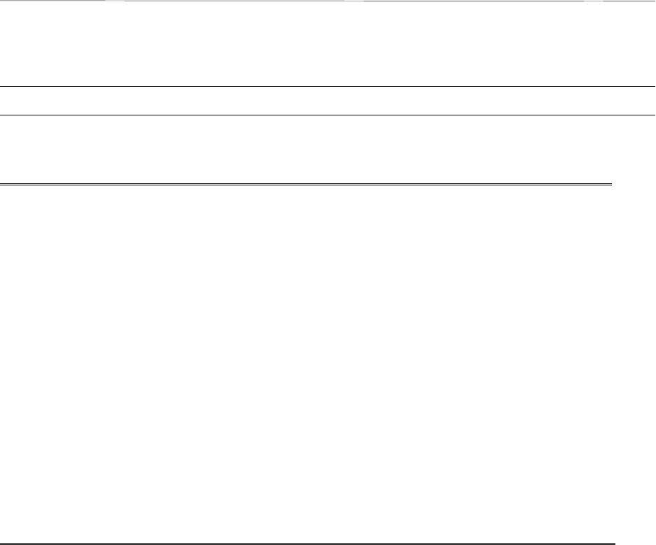
007-5510-002
129
A
Controller Technical Specifications
The following are the technical specifications of the SGI InfiniteStorage 15000 controller.
NOTE :
Specifications subject to change without notice.
Configuration, Performance, & Capacity
Host interface IB 4xDDR, FC-8
Drive interface SAS
Management interface RS-232 and Ethernet (Telnet)
Cache memory 2.5GB
Independent drive channels 10
Number of host ports 4
Number of host connections Up to 512
Number of drives supported Up to 1200 (1000 drives for data)
Number of LUN groups supported Up to 1024
Hot spare capability Yes
Full duplex 10/100/1000 BaseT onboard Yes
Reliability
SES (SCSI Enclosure Services) protocol
support Yes
Temperature monitoring Yes
Redundant hot-swappable power supplies 2
Redundant hot-swappable cooling fans 3

130
007-5510-002
Physical, Power & Environmental
Controller chassis
(H×W×D, Weight) 3.5" × 19.0" × 31", 45lbs
Electrical/AC 100-120V / 200-240V @ 47-63Hz
Power consumption (maximum
current) 2.65A @ 208VAC
Couplet: 8.0A @ 110VAC, 3.8A @ 230VAC
Power consumption (average
current) 3.0A @ 110VAC, 1.5A @ 230VAC
Couplet: 6.0A @ 110VAC, 4.2 @ 208VAC
Operating environment
(temperature / relative humidity) 5°C to 35°C / 20% - 80%,
non-condensing (at sea level)
Non-operating environment
(temperature/ relative humidity) -10°C to 50°C / 20% - 80%, non-condensing
Thermal rating (single mode/dual
mode) 1880 BTU / 3760 BTU
Certification UL, CE, CUL, C-Tick, FCC
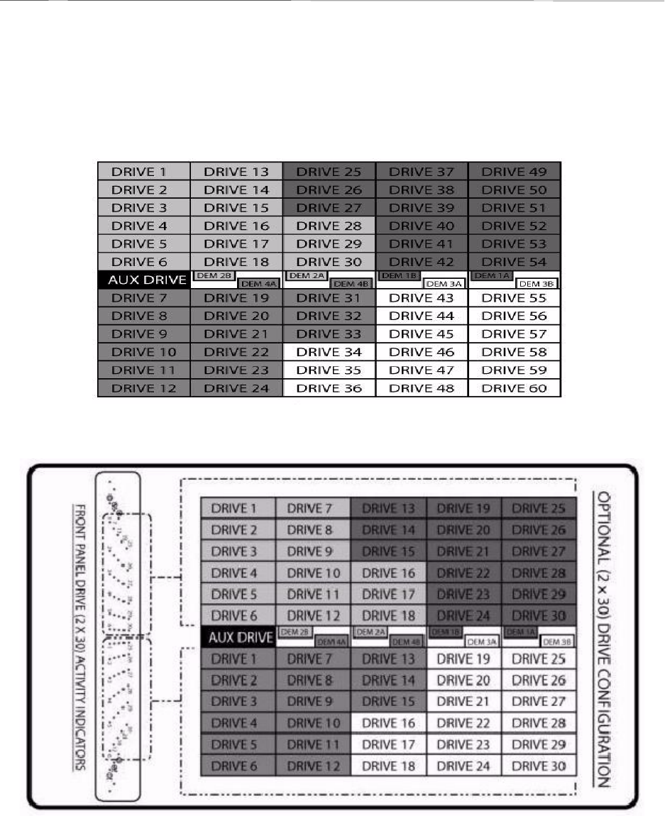
007-5510-002
131
B
Drive Addressing
This appendix illustrates the drive addressing for the disk enclosures. There are two drive numbering options:
• 1 x 60 (one set of drives 1 through 60); (Figures B-1and B-3).
• 2 x 30 (two sets of drives 1 through 30); (Figures B-2 and B-4)
Figure B–1 1x60 Drive Layout Configuration
Figure B–1 2x30 Drive Layout Configuration
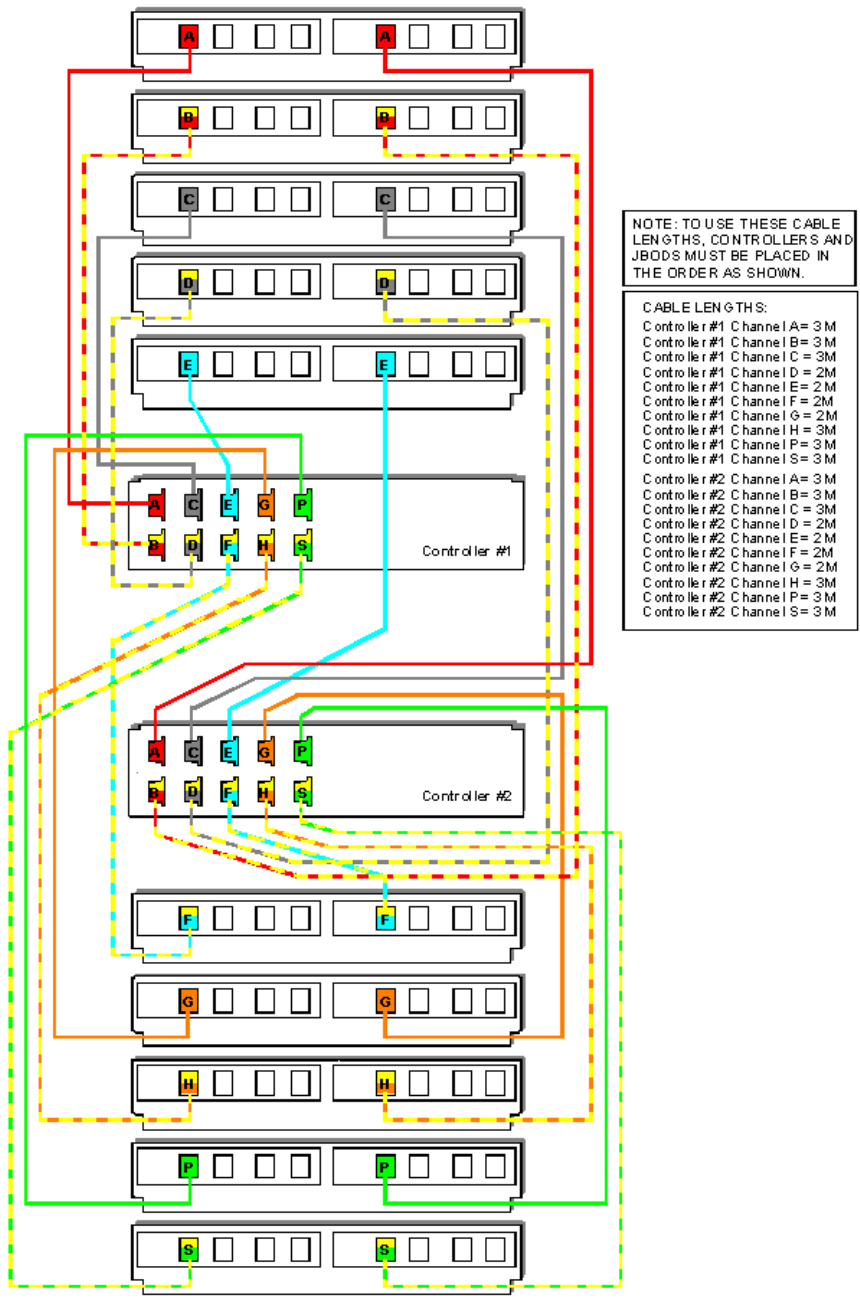
132
007-5510-002
Figure B–3 Controller-Drive Enclosure Couplet (1x Configuration)
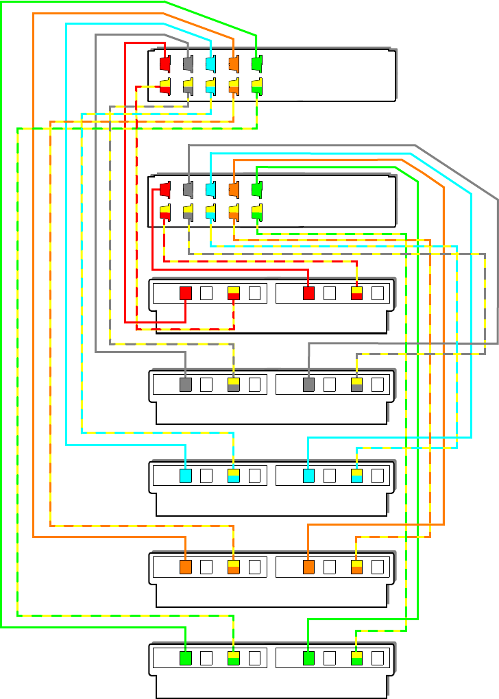
007-5510-002
133
Figure B–4 Controller-Drive Enclosure Couplet (2x Configuration)
PSPS
A
B
C
D
E
F
G
H
P
S
EE F
ABA
CD
GHG
B
D
H
F
C
A
B
C
D
E
F
G
H
P
S
Controller #1
Controller #2
Channel A/B
Channel C/D
Channel E/F
Channel G/H
Channel P/S

007-5510-002
135
C
Cabling Controllers and Drive Enclosures
This appendix illustrates the proper cabling of the following two configurations:
• 2 controllers and 5 drive enclosures (Figures C–1 and C–2)
• 2 controllers and 10 drive enclosures (Figures C–3 and C–4)
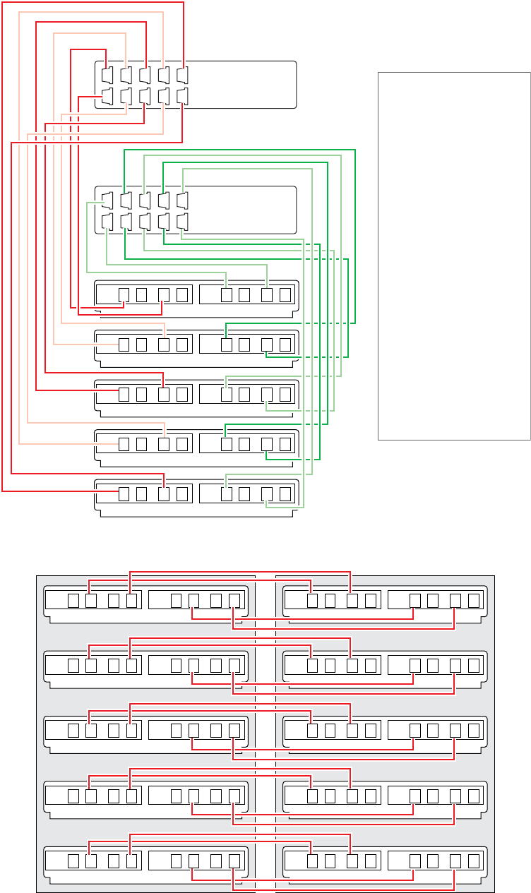
136
007-5510-002
Figure C–1 Controller Cabling (2 Controllers and 5 Drive Enclosures)
Figure C–2 Drive Enclosure Cabling (2 Controllers and 5 Drive Enclosures)
A A
Channel A/B
C C
Channel C/D
E E
Channel E/F
G G
Channel G/H
P P
Channel P/S
A C E G P
B D F H S Controller 2
A C E G P
B D F H S Controller 1
BB
DD
FF
HH
SS
Note: To use these cable
lengths, controller 1 must be
on top and controller 2 must
be on the bottom.
Cable lengths:
Controller 1 Channel A = 2M
Controller 1 Channel B = 2M
Controller 1 Channel C = 2M
Controller 1 Channel D = 2M
Controller 1 Channel E = 3M
Controller 1 Channel F = 3M
Controller 1 Channel G = 3M
Controller 1 Channel H = 3M
Controller 1 Channel P = 3M
Controller 1 Channel S = 3M
Controller 2 Channel A = 2M
Controller 2 Channel B = 2M
Controller 2 Channel C = 2M
Controller 2 Channel D = 2M
Controller 2 Channel E = 3M
Controller 2 Channel F = 3M
Controller 2 Channel G = 3M
Controller 2 Channel H = 3M
Controller 2 Channel P = 3M
Controller 2 Channel S = 3M
A A
C C
E E
G G
P P
A A
C C
E E
G G
P P
BB
DD
FF
HH
SS
BB
DD
FF
HH
SS
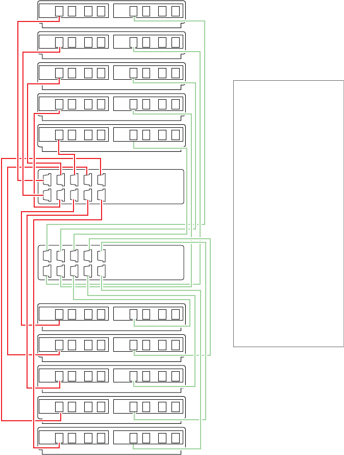
007-5510-002
137
Figure C–3 Controller Cabling (2 Controllers and 10 Drive Enclosures)
A A
Channel A
B B
Channel B
C C
Channel C
D D
Channel D
E E
Channel E
F F
Channel F
G G
Channel G
H H
Channel H
P P
Channel P
S S
Channel S
A C E G P
B D F H S Controller 2
A C E G P
B D F H S Controller 1
Note: To use these cable
lengths, controllers and
jbods must be placed in
the order as shown.
Cable lengths:
Controller 1 Channel A = 3M
Controller 1 Channel B = 3M
Controller 1 Channel C = 3M
Controller 1 Channel D = 2M
Controller 1 Channel E = 2M
Controller 1 Channel F = 2M
Controller 1 Channel G = 2M
Controller 1 Channel H = 3M
Controller 1 Channel P = 3M
Controller 1 Channel S = 3M
Controller 2 Channel A = 3M
Controller 2 Channel B = 3M
Controller 2 Channel C = 3M
Controller 2 Channel D = 2M
Controller 2 Channel E = 2M
Controller 2 Channel F = 2M
Controller 2 Channel G = 2M
Controller 2 Channel H = 3M
Controller 2 Channel P = 3M
Controller 2 Channel S = 3M
138
007-5510-002
Figure C–4 Drive Enclosure Cabling (2 Controllers and 10 Drive Enclosures)
A A
B B
C C
D D
E E
F F
G G
H H
P P
S S
A A
B B
C C
D D
E E
F F
G G
H H
P P
S S
