Aperto Networks SR1001-A1 2.5 GHz Subscriber Radio User Manual Cover PW200PW
Aperto Networks 2.5 GHz Subscriber Radio Cover PW200PW
Users Manual

PacketWave 200 Series
Subscriber Equipment Manual
10004880
Rev E1, June 2005
PacketWave
Fixed Wireless Broadband Access System
PacketWave 200 Series
Subscriber Equipment
Installation and Operation Manual
PacketWave 200 Installation and Operation
©Copyright 2003 by Aperto Networks
All rights reserved.
Specifications subject to change.
Aperto, PacketWave, and WaveCenter are trademarks of Aperto Networks.
All other trademarks used herein are the property of their respective owners.
Aperto Networks
1637 South Main Street
Milpitas, CA 95035 USA
Phone: 408.719.9977
Fax: 408.719.9970
www.apertonet.com

iii
10004880, Rev. E1
Regulatory Information
Part 15
This device complies with Part 15 of the FCC Rules. Operation is subject to the following
two conditions:
• this device may not cause harmful electromagnetic interference, and
• this device must accept any interference received including interference that may
cause undesired operations.
FCC Notice: Radio and Television Interference
The PacketWave 200 Series Subscriber Equipment has been tested and found to comply
with the limits for a Class B digital device, pursuant to Part 15 of the FCC Rules. These
limits are designed to provide reasonable protection against harmful interference in a res-
idential installation. This equipment generates, uses, and can radiate radio frequency
energy and, if not installed and used according to the instructions, may cause harmful
interference to radio communications. However, there is no guarantee that interference
will not occur in a particular installation. If this equipment does cause harmful interfer-
ence to radio or television reception, which is found by turning the equipment off and on,
the user is encouraged to try to correct the interference by one or more of the following
measures:
• Reorient or relocate the receiving antenna.
• Increase the separation between the equipment or device.
• Connect the equipment to an outlet other than the receiver's.
• Consult a dealer or an experienced radio/TV technician for assistance.

iv
10004880, Rev. E1
RF Exposure Notice
The installer shall mount all transmit antennas so as to comply with the limits for human expo-
sure to radio frequency (RF) fields per paragraph 1.1307 of FCC regulations. The FCC
requirements incorporate limits for Maximum Permissible Exposure (MPE) in terms of elec-
tric field strength, magnetic field strength, and power density.
CAUTION: 5.8 GHz ISM — To comply with FCC RF exposure requirements, antennas
used for this device must be installed to provide a separation distance of at
least 1.5m from all persons to satisfy RF exposure compliance.
CAUTION: 2.5 GHz MMDS — To comply with FCC RF exposure requirements in sec-
tion 1.1307, a minimum separation distance of 20 cm is required between
this antenna and all persons.
Canadian Standards Compliance
This Class B digital apparatus complies with Canadian ICES-003
Cet appareil numérique de la classe B est conforme
à la norme NMB-003 du Canada

v
10004880, Rev. E1
CE Notice
Declaration of Conformity
Aperto Networks Inc. of 1637 S. Main Street, Milpitas CA 95037, USA, declare under our
sole responsibility that the product PacketWave 3.5 GHz system (3.4-3.7 GHz operation) to
which this declaration relates, is in conformity with the following standards and/or other nor-
mative documents.
• EN 301 753
• EN301 489-4
• EN60950
We hereby declare that all essential radio test suites have been carried out and that the above
named product is in conformity to all the essential requirements of Directive 1999/5/EC.
The conformity assessment procedure referred to in Article 10 and detailed in Annex [III] or
[IV] of Directive 1999/5/EC has been followed with the involvement of the following Notified
Body: Compliance Certification Services, 561F Monterey Road, Morgan Hill, CA 95037
0984

vi
10004880, Rev. E1
The PacketWave 3.5 GHz system is approved in the following countries:
Country Lower band Upper band
Austria 3,510 - 3,549 3,560 - 3,599
Belgium 3,450 - 3,500 3,550 - 3,600
Denmark 3,410 - 3,490 3,510 - 3,590
Finland 3,410 - 3,500 3,510 - 3,600
France 3,465 - 3,495 3,565 - 3,595
Germany 3,410 - 3,580
Greece 3,410 - 3,438
3,459 - 3,473
3,476.5 - 3,497.5
3,510 - 3,538
3,559 - 3,573
3,576.5 - 3,597.5
Iceland 3,400 - 3,600
Ireland 3,410 - 3,4353,475 -
3,500
3,510 - 3,5353,575 -
3,600
Netherlands 3,500 - 3,530 3,550 - 3,580
Norway 3,413.5 - 3,500 3,513.5 - 3,600
Portugal 3,410 - 3,4383,600 -
3,800
3,510 - 3,538
Spain 3,400 - 3,460 3,500 - 3,560
Sweden 3,400 - 3,600
Switzerland 3,410 - 3,500 3,510 - 3,600
UK 3,480 - 3,500 3,580 - 3,600
vii
10004880, Rev. E1
UL Information
CAUTION: For the CATV system, the CATV installer should install in accordance with
Article 820-40 of the NEC which provides guidelines for proper ground-
ing and, in particular, specifies that the cable ground shall be connected
to the grounding system of the building, as close as possible to the
point of cable entry as practical.
CAUTION: The external exposed (outdoor) run of the cables, from the exit of the
building to the antenna/radio assembly, should be less than 140ft,
while the total cable run is as described in this manual.
CAUTION: For the Model 1xx, the Subscriber Unit and its power supply is intended
to be installed indoors in a dry location only. Only the Radio/Antenna
assembly is intended to be installed outdoors.
CAUTION: For the Model 2xx system, the Interface Box and its power supply is
intended to be installed indoor only. Only the Radio/Antenna assembly
is intended to be installed outdoors

viii
10004880, Rev. E1
Waste Electrical and Electronic Equipment (WEEE) Directive Compliance
Aperto Network products sold within the European Union (EU) are subject to
the requirements of the Waste Electrical and Electronic Equipment (WEEE)
Directive; as implemented by national legislation in each EU country. The
objectives of the Directive are to reduce the environmental impacts of
WEEE by promoting re-use and recycling, as an alternative to disposal.
From 13 August 2005, product placed on the EU market is required to be
marked with the symbol shown below. This symbol indicates that end-of-life
electronic equipment generated within the EU should not be mixed with
other types of waste or placed in the general waste stream; but should be
segregated for the purpose of re-use or recycling.

ix
10004880, Rev. E1

xi
10004880 Rev. D1
Preface
This manual is part of the documentation for the PacketWave broadband wireless system for
delivering high-speed subscriber services. The PacketWave documentation set includes:
• PacketWave 1000 Base Station Unit Installation, Configuration, and Operation Manual:
part number 10002690.
• PacketWave 100 Series Subscriber Equipment Installation and Operation Manual: part
number 10002689.
• PacketWave 200 Series Subscriber Equipment Installation and Operation Manual: part
number 10004880.
Scope of This Manual
This manual documents the installation and operation of the PacketWave 200 Series subscriber
equipment with software version 4.1.
This manual provides the following information:
•A QuickStart section for rapidly placing PacketWave 200 Series subscriber equipment
in operation.
• Descriptions of the PacketWave 200 Series hardware components.
• Complete site planning and installation instructions for PacketWave 200 Series sub-
scriber equipment, including the indoor bridge/router unit and the outdoor radio/
antenna unit.
• Descriptions of the PacketWave 200 Series software components, including the Web
GUI and the Aperto Installation Manager, and instructions for using them.
• IP addressing guidelines for the local PC(s).
• Procedures for initializing the PacketWave 200 Series subscriber equipment.
Complete descriptions of the PacketWave System, its components, the installation of the cell
site equipment, and overall system configuration and operation are provided in the PacketWave
1000 Base Station Unit Installation, Configuration, and Operation manual.
Preface
xii
10004880 Rev. D1
Conventions Used in This Manual
PacketWave manuals represent special kinds of text as follows:
• Files names and URLs are represented in italics, with variables described inside angle
brackets. For example, if the URL http://<IP address>/bsu.htm is referenced, you will
replace the variable <IP address> with the appropriate real IP address.
• Management interface text is represented in a bold font: for example, the Generate
Config File button.
• Labels on equipment are represented in a bold font: for example, the Control connector.
WARNING: This format is used to indicate the possibility of personal injury or damage
to equipment.
CAUTION: This format is used to indicate the possibility of system or equipment oper-
ation problems.
Items of special importance will be marked by a pointing-hand icon, as this paragraph is.
Intended Audience for this Manual
This manual is intended primarily for subscriber equipment installers. It also presents infor-
mation of use to subscribers, including a discussion of the Web GUI.
Installation of radio equipment involves numerous factors requiring considerable expertise. It
is assumed that equipment installers are professionals with a full understanding of the princi-
ples and standard practices and procedures of cell site installation, with all relevant safety
requirements, and with applicable local building codes.

xiii
10004880 Rev. D1
Preface
General Cautions and Warnings
Observe the following when installing or operating any PacketWave System components.
Carefully follow all local building and electrical codes, especially the latest revision of
the National Electrical Code (NEC) and standard safety procedures for installing and
working with this type of equipment. Improper procedures or installation can result in
damage to the equipment or the building, and injury or death. If you are not sure about
whether the installation follows these codes, contact a licensed building inspector or elec-
trician in the area for assistance.
Always use quality components—including cables, connectors, mounts, etc.—specifically
rated for your particular environmental conditions and system performance requirements.
Always use appropriate tools, and follow the instructions of the tool manufacturers.
All outdoor installation, including equipment mounting and cabling, should be performed
by trained microwave radio technicians familiar with usual and customary practices and
procedures.
Take extreme care to avoid contacting any overhead power lines, lights, and power circuits
while you are installing the Outdoor Unit. Contact with any of these objects could cause
injury or death. Do not install the Outdoor Unit near power lines.
Make sure that the outdoor radio/antenna is grounded in accordance with local, state, fed-
eral, and National Electrical Code (NEC) requirements. Pay special attention to NEC
sections 810 and 820. See the instructions in Chapter 4 of this manual.
For the PacketWave 200 Series Interface Box, use an outlet that contains surge protection
and ground fault protection, or use a surge protection device. This will protect the Pack-
etWave 200 Series equipment connected to it from damage resulting from AC current
surges, lightning, etc. For complete protection, all connections to the Interface Box (i.e.,
from radio/antenna and PC/hub) should be connected to a surge protection device. To
ensure the best signal, use surge protectors designed for the specific application.
Because Aperto Networks cannot be responsible for improper installation or use of its equip-
ment, failure to follow these and other published cautions and warnings may void your equip-
ment warranty.

Preface
xiv
10004880 Rev. D1

i
Rev. E1, June 2005
Table of Contents
Regulatory Information . . . . . . . . . . . . . . . . . . . . . . . . . . . . . . . . . . . . . . . . . . . . . . . . . . . . . . . . . iii
Scope of This Manual . . . . . . . . . . . . . . . . . . . . . . . . . . . . . . . . . . . . . . . . . . . . . . . . . . . . . . . . . . xi
Conventions Used in This Manual . . . . . . . . . . . . . . . . . . . . . . . . . . . . . . . . . . . . . . . . . . . . . . . . xii
Intended Audience for this Manual . . . . . . . . . . . . . . . . . . . . . . . . . . . . . . . . . . . . . . . . . . . . . . . xii
General Cautions and Warnings . . . . . . . . . . . . . . . . . . . . . . . . . . . . . . . . . . . . . . . . . . . . . . . . . . xiii
Chapter 1. QuickStart Guide
Chapter 2. Overview
Models and Functionality . . . . . . . . . . . . . . . . . . . . . . . . . . . . . . . . . . . . . . . . . . . . . . . . . . . . . . . 2-1
VLAN and PPPoE/PPP . . . . . . . . . . . . . . . . . . . . . . . . . . . . . . . . . . . . . . . . . . . . . . . . . . . 2-1
Subscriber Equipment . . . . . . . . . . . . . . . . . . . . . . . . . . . . . . . . . . . . . . . . . . . . . . . . . . . . . . . . . 2-3
Outdoor Unit . . . . . . . . . . . . . . . . . . . . . . . . . . . . . . . . . . . . . . . . . . . . . . . . . . . . . . . . . . 2-3
Indoor Unit . . . . . . . . . . . . . . . . . . . . . . . . . . . . . . . . . . . . . . . . . . . . . . . . . . . . . . . . . . . 2-4
Interface Box . . . . . . . . . . . . . . . . . . . . . . . . . . . . . . . . . . . . . . . . . . . . . . . . . . . . . . . . . . 2-4
Management, Configuration, and Diagnostics . . . . . . . . . . . . . . . . . . . . . . . . . . . . . . . . . . . . . . 2-5
SU Configuration . . . . . . . . . . . . . . . . . . . . . . . . . . . . . . . . . . . . . . . . . . . . . . . . . . . . . . . 2-6
Built-In Server, Client, Agent, and Router Functions . . . . . . . . . . . . . . . . . . . . . . . . . . 2-6
PacketWave 200 LEDs . . . . . . . . . . . . . . . . . . . . . . . . . . . . . . . . . . . . . . . . . . . . . . . . . . 2-7
SNMP . . . . . . . . . . . . . . . . . . . . . . . . . . . . . . . . . . . . . . . . . . . . . . . . . . . . . . . . . . . . . . . . 2-7
Event Reporting . . . . . . . . . . . . . . . . . . . . . . . . . . . . . . . . . . . . . . . . . . . . . . . . . . . . . . . . 2-8
Chapter 3. Site Planning
Location of the Interface Box . . . . . . . . . . . . . . . . . . . . . . . . . . . . . . . . . . . . . . . . . . . . . . . . . . . . 3-1
Location of the Outdoor Unit (ODU) . . . . . . . . . . . . . . . . . . . . . . . . . . . . . . . . . . . . . . . . . . . . . . . 3-1
Cables and Cable Path . . . . . . . . . . . . . . . . . . . . . . . . . . . . . . . . . . . . . . . . . . . . . . . . . . . . . . . . . 3-2
Subscriber LAN/Computer . . . . . . . . . . . . . . . . . . . . . . . . . . . . . . . . . . . . . . . . . . . . . . . . . . . . . . 3-2
Table of
Contents

ii
Rev. E1, June 2005
Table of Contents
Chapter 4. Subscriber Equipment Installation
Installation Requirements . . . . . . . . . . . . . . . . . . . . . . . . . . . . . . . . . . . . . . . . . . . . . . . . . . . . . . 4-3
Mounting the Outdoor Unit . . . . . . . . . . . . . . . . . . . . . . . . . . . . . . . . . . . . . . . . . . . . . . . . . . . . . . 4-3
Grounding the Outdoor Unit . . . . . . . . . . . . . . . . . . . . . . . . . . . . . . . . . . . . . . . . . . . . . . . . . . . . . 4-6
Positioning the Interface Box . . . . . . . . . . . . . . . . . . . . . . . . . . . . . . . . . . . . . . . . . . . . . . . . . . . . 4-8
Connecting the ODU to the Interface Box . . . . . . . . . . . . . . . . . . . . . . . . . . . . . . . . . . . . . . . . . . 4-8
Connecting to the Local Computer or LAN . . . . . . . . . . . . . . . . . . . . . . . . . . . . . . . . . . . . . . . . . . 4-10
Powering Up the PacketWave 200 . . . . . . . . . . . . . . . . . . . . . . . . . . . . . . . . . . . . . . . . . . . . . . . . 4-11
Aligning the Antenna Using Audio Auto-Alignment Mode . . . . . . . . . . . . . . . . . . . . . . . . . . . . . 4-11
Connection to the PacketWave Network . . . . . . . . . . . . . . . . . . . . . . . . . . . . . . . . . . . . . . . . . . . 4-12
Setting Up the Local Computer(s) . . . . . . . . . . . . . . . . . . . . . . . . . . . . . . . . . . . . . . . . . 4-12
Chapter 5. The PacketWave AIM
Installing the AIM Software on the PC . . . . . . . . . . . . . . . . . . . . . . . . . . . . . . . . . . . . . . . . . . . . . 5-1
Connecting to the PacketWave 200 . . . . . . . . . . . . . . . . . . . . . . . . . . . . . . . . . . . . . . . . . . . . . . . 5-2
Using the Aperto Installation Manager . . . . . . . . . . . . . . . . . . . . . . . . . . . . . . . . . . . . . . . . . . . . 5-4
Downloading the BSU’s IM.DAT File . . . . . . . . . . . . . . . . . . . . . . . . . . . . . . . . . . . . . . . 5-6
Basic Configuration . . . . . . . . . . . . . . . . . . . . . . . . . . . . . . . . . . . . . . . . . . . . . . . . . . . . 5-7
Aligning the Antenna . . . . . . . . . . . . . . . . . . . . . . . . . . . . . . . . . . . . . . . . . . . . . . . . . . . 5-12
Viewing Status of the Wireless Link (Link Status Mode) . . . . . . . . . . . . . . . . . . . . . . . 5-16
Running a Non-Destructive Test (Test Mode) . . . . . . . . . . . . . . . . . . . . . . . . . . . . . . . . 5-18
Pre-provisioning a PW200 for Later Installation (Provision Mode) . . . . . . . . . . . . . . . 5-19
Aperto Installation Manager Troubleshooting . . . . . . . . . . . . . . . . . . . . . . . . . . . . . . . . . . . . . . 5-20
Problems Connecting to the Subscriber Unit . . . . . . . . . . . . . . . . . . . . . . . . . . . . . . . . 5-20
Problems Communicating with the Base Station Unit . . . . . . . . . . . . . . . . . . . . . . . . . 5-20
Chapter 6. The Web GUI
ISP and Subscriber Logon Levels . . . . . . . . . . . . . . . . . . . . . . . . . . . . . . . . . . . . . . . . . . . . . . . . . 6-1
Accessing the Web Interface . . . . . . . . . . . . . . . . . . . . . . . . . . . . . . . . . . . . . . . . . . . . . . . . . . . . 6-2
Features of the Web Interface . . . . . . . . . . . . . . . . . . . . . . . . . . . . . . . . . . . . . . . . . . . . . . . . . . . . 6-3
Home Page: Connectivity View . . . . . . . . . . . . . . . . . . . . . . . . . . . . . . . . . . . . . . . . . . . . 6-3
Main Menu and Submenu . . . . . . . . . . . . . . . . . . . . . . . . . . . . . . . . . . . . . . . . . . . . . . . 6-4
Submitting and Uploading Changes . . . . . . . . . . . . . . . . . . . . . . . . . . . . . . . . . . . . . . . 6-5
Cancel and Refresh Buttons . . . . . . . . . . . . . . . . . . . . . . . . . . . . . . . . . . . . . . . . . . . . . . 6-5
Hyperlinks . . . . . . . . . . . . . . . . . . . . . . . . . . . . . . . . . . . . . . . . . . . . . . . . . . . . . . . . . . . . 6-5
Overview of SU Web GUI Functions . . . . . . . . . . . . . . . . . . . . . . . . . . . . . . . . . . . . . . . . . . . . . . . 6-5
Configuration Pages . . . . . . . . . . . . . . . . . . . . . . . . . . . . . . . . . . . . . . . . . . . . . . . . . . . . . . . . . . . 6-7
System Configuration . . . . . . . . . . . . . . . . . . . . . . . . . . . . . . . . . . . . . . . . . . . . . . . . . . . 6-7
Administration Configuration . . . . . . . . . . . . . . . . . . . . . . . . . . . . . . . . . . . . . . . . . . . . . 6-7
Password Configuration . . . . . . . . . . . . . . . . . . . . . . . . . . . . . . . . . . . . . . . . . . . . . . . . . 6-7
Ethernet Configuration . . . . . . . . . . . . . . . . . . . . . . . . . . . . . . . . . . . . . . . . . . . . . . . . . . 6-10
SNMP Configuration . . . . . . . . . . . . . . . . . . . . . . . . . . . . . . . . . . . . . . . . . . . . . . . . . . . . 6-11
VLAN Configuration . . . . . . . . . . . . . . . . . . . . . . . . . . . . . . . . . . . . . . . . . . . . . . . . . . . . . 6-12
VLAN Classifier Configuration . . . . . . . . . . . . . . . . . . . . . . . . . . . . . . . . . . . . . . . . . . . . 6-13
Wireless Interface Configuration . . . . . . . . . . . . . . . . . . . . . . . . . . . . . . . . . . . . . . . . . . 6-14

iii
Rev. E1, June 2005
Table of Contents
Default Best Effort Configuration . . . . . . . . . . . . . . . . . . . . . . . . . . . . . . . . . . . . . . . . . . 6-16
Routes Configuration . . . . . . . . . . . . . . . . . . . . . . . . . . . . . . . . . . . . . . . . . . . . . . . . . . . 6-17
NAT Configuration . . . . . . . . . . . . . . . . . . . . . . . . . . . . . . . . . . . . . . . . . . . . . . . . . . . . . . 6-19
DHCP Configuration . . . . . . . . . . . . . . . . . . . . . . . . . . . . . . . . . . . . . . . . . . . . . . . . . . . . 6-23
IP Filter Configuration . . . . . . . . . . . . . . . . . . . . . . . . . . . . . . . . . . . . . . . . . . . . . . . . . . . 6-26
PPPoE/PPP Configuration . . . . . . . . . . . . . . . . . . . . . . . . . . . . . . . . . . . . . . . . . . . . . . . . 6-28
Device Control Utility . . . . . . . . . . . . . . . . . . . . . . . . . . . . . . . . . . . . . . . . . . . . . . . . . . . . . . . . . . . 6-30
Fault Reporting Pages . . . . . . . . . . . . . . . . . . . . . . . . . . . . . . . . . . . . . . . . . . . . . . . . . . . . . . . . . . 6-31
Event Log Page . . . . . . . . . . . . . . . . . . . . . . . . . . . . . . . . . . . . . . . . . . . . . . . . . . . . . . . . 6-31
E-mail Configuration Page . . . . . . . . . . . . . . . . . . . . . . . . . . . . . . . . . . . . . . . . . . . . . . . 6-32
Status Pages . . . . . . . . . . . . . . . . . . . . . . . . . . . . . . . . . . . . . . . . . . . . . . . . . . . . . . . . . . . . . . . . . 6-33
Performance Pages . . . . . . . . . . . . . . . . . . . . . . . . . . . . . . . . . . . . . . . . . . . . . . . . . . . . . . . . . . . . 6-36
Debug Page . . . . . . . . . . . . . . . . . . . . . . . . . . . . . . . . . . . . . . . . . . . . . . . . . . . . . . . . . . . . . . . . . . 6-39
Chapter 7. Specifications
General Specifications . . . . . . . . . . . . . . . . . . . . . . . . . . . . . . . . . . . . . . . . . . . . . . . . . . . . . . . . . A-1
Outdoor Unit Specifications . . . . . . . . . . . . . . . . . . . . . . . . . . . . . . . . . . . . . . . . . . . . . . . . . . . . . A-3
Chapter 8. Event Reporting
Chapter 9. Diagnostic Manager
Loading the Diagnostic Manager Software onto the PC . . . . . . . . . . . . . . . . . . . . . . . . . . . . . . . C-1
Running the Diagnostic Manager . . . . . . . . . . . . . . . . . . . . . . . . . . . . . . . . . . . . . . . . . . . . . . . . . C-1
Chapter 10. Command Line Interface (CLI)
Accessing and Using the CLI . . . . . . . . . . . . . . . . . . . . . . . . . . . . . . . . . . . . . . . . . . . . . . . . . . . . D-1
Commands . . . . . . . . . . . . . . . . . . . . . . . . . . . . . . . . . . . . . . . . . . . . . . . . . . . . . . . . . . . D-2
Error Messages . . . . . . . . . . . . . . . . . . . . . . . . . . . . . . . . . . . . . . . . . . . . . . . . . . . . . . . . D-2
Chapter 11. ODU Cables

Table of Contents
iv
Rev. E1, June 2005

1–1
10004880 Rev. D1
1
QuickStart Guide
This chapter outlines the basic procedure for installing PacketWave 200 Series Subscriber
Equipment and putting it into operation. It identifies the minimal requirements for getting
the equipment up and running, and assumes that configuration using DHCP and
WaveCenter™ Configuration Manager has been performed as described in the
PacketWave 1000 Base Station Unit
manual.
WARNING: Outdoor installation procedures should be performed by qualified pro-
fessionals following all safety and other requirements and acting in
accordance with standard practices and procedures. Failure to meet
safety requirements and/or non-standard practices and procedures
could result in personal injury and/or damage to equipment.
Step 1. Prepare for Installation
A. Before visiting the subscriber’s site:
i. Make sure that the necessary system configuration has taken place (as
described in the
PacketWave 1000 Base Station Unit
manual).
ii. Verify that the Subscriber Unit configuration file has been created using Config-
uration Manager and either saved on the BSU’s TFTP server, or (for local config-
uration mode) saved on a disk and provide to the installer.
iii. Verify that the DHCP server has been configured with the Subscriber Equip-
ment’s IP and MAC addresses and its configuration file name. Make a note of
the IP address for use during installation.
iv. Verify that the DHCP and TFTP servers have the appropriate route to the
Subscriber Unit installed.
v. To perform PC-less installation using the auto-alignment feature, use the Aperto
Installation Manager (AIM) utility in Provision mode to pre-configure the Sub-
scriber Unit. For local configuration mode (see step ii above), click on Import CM
database and specify the configuration file location and name.
Chapter 1. QuickStart Guide
1–2
10004880 Rev. D1
B. At the subscriber’s site:
i. Identify the location for the Interface Box, close to an AC power source.
ii. Identify an appropriate location for mounting the Outdoor Unit (ODU). In most
cases, the unit should be pointed at the base station with the least possible
obstruction.
iii. Determine the cable path between the Interface Box and the Outdoor Unit. Max-
imum cable length is 50 m (165 ft) or 100 m (330 ft), depending on cable type
(see Table 3-A).
Step 2. Install the Interface Box
A. Run the Ethernet cable from the location for the ODU to the location for the Interface
Box. Leave plenty of slack. Place the protective rubber boot at the outdoor end. Ter-
minate both ends with shielded RJ-45 connectors.
It is highly recommended that the cable is verified using a cable tester before connec-
tion and power-up.
B. Plug the power supply attached to the Interface Box into an AC power outlet.
C. Connect the cable from the ODU into the RJ-45 jack labeled ODU.
Step 3. Install the Outdoor Unit (ODU)
A. If a mounting pole or other support is to be employed, install it in the chosen location,
following standard procedures and local building codes. The Outdoor Unit’s standard
mounting bracket accommodates pole diameters of 1.5 or 2 inches (3.8 or 5.1 cm).
B. Mount the Outdoor Unit to the pole or other support or to the building.
WARNING: Lightning protection is recommended for subscriber equipment. Instruc-
tions and an example are contained in the document titled
Surge Protec-
tion for PacketWave Products
, included on the CD that accompanies the
equipment. (If the CD or document were not provided, contact Aperto Cus-
tomer Service.) Lightning damage is not covered by the product warranty.
C. Connect the cable from the Interface Box into the RJ-45 jack on the ODU. (See
Appendix E for cable details.) Make sure the boot is properly seated in the mating
flange cutout. The boot should be flush with the radio housing. Secure the boot to the
radio housing with the screws provided. Secure the exit point of the cable from the
boot with a cable tie.
WARNING: There is DC power on the Interface Box’s ODU port. Connecting this port to
a PC or switch will cause permanent damage to the device.

1–3
10004880 Rev. D1
Chapter 1. QuickStart Guide
Step 4. Align the Antenna
A. Verify that the Ethernet cable from the Interface Box to the Outdoor Unit is properly
connected.
B. If the PacketWave 200 has been pre-provisioned as described in Step 1, the Outdoor
Unit will begin beeping, indicating that it is in auto-alignment mode. (If beeping does
not occur, the PacketWave 200 has not been pre-provisioned, and you will need to
use the AIM to align the antenna as described in Chapter 5.)
C. Initially, the audio signal will alternate between a long beep and a long silence. The
beep is an audio indication of the strength of the signal being received from the base
station. As signal reception gets stronger, the beeps increase in pitch and frequency,
becoming a continuous tone when the signal is optimal.
D. Adjust the position of the ODU for the highest pitch and frequency of the beeping,
ideally finding a position which results in a continuous tone. Secure the ODU in that
position.
E. When the ODU receives a continuously strong signal for one minute (specifically,
when the signal-to-noise ratio is higher than 16 dB and the signal strength is greater
than -88 dB without varying by more than 2 dB for one minute), the PacketWave 200
will become operational with an audio tone similar to a telephone ringing.
F. If such a signal is not obtained, auto-alignment mode will last until power is removed,
and the PacketWave 200 will not become operational. Antenna alignment will have to
be performed using the Aperto Installation Manager as described in Chapter 4.
Step 5. Configure Subscriber Hosts
A. Connect the subscriber’s hub/switch or computer to the RJ-45 jack labeled LAN on the
Interface Box.
-Use a straight Ethernet cable for connection to a hub/switch or a crossover
Ethernet cable for connection directly to a computer.
B. The Subscriber Unit has a built-in DHCP server when it is in NAT or router mode
(PacketWave 120 and 130). The DHCP server is enabled by default and can support a
maximum of 100 users on the subscriber’s LAN. If the DHCP server will be used, con-
figure this feature using the Configuration Manager, and configure the host’s TCP/IP
to obtain its IP address using DHCP.
C. Alternatively, the host may be statically configured with an IP address, default gate-
way, and DNS server. If the Subscriber Unit is in bridge mode, the default gateway
could be the IP address of the Base Station’s Wireless Subsystem (WSS) that the Sub-
scriber Unit connects to. For a Subscriber Unit in NAT or router mode, the default gate-
way for the subscriber’s hosts is the Subscriber Unit’s LAN IP address.
NOTE: To fully remove a Subscriber Unit from deployment, the configuration file
must be removed from all TFTP servers. DHCP server must download configura-
tion information before it becomes operational. This is performed by TFTP proto-

Chapter 1. QuickStart Guide
1–4
10004880 Rev. D1
col, which is routed. Two IP addresses may be given for the TFTP server to provide
for redundancy.

2–1
10004880 Rev. D1
2
Overview
As part of Aperto Networks' PacketWave Broadband Multiservice Wireless Access System,
PacketWave 200 Series Subscriber Units delivers high-speed, always-on Internet access to
small and medium-sized businesses, small offices/home offices (SOHO), and residences.
Models and Functionality
There are three models in the PacketWave 200 Series:
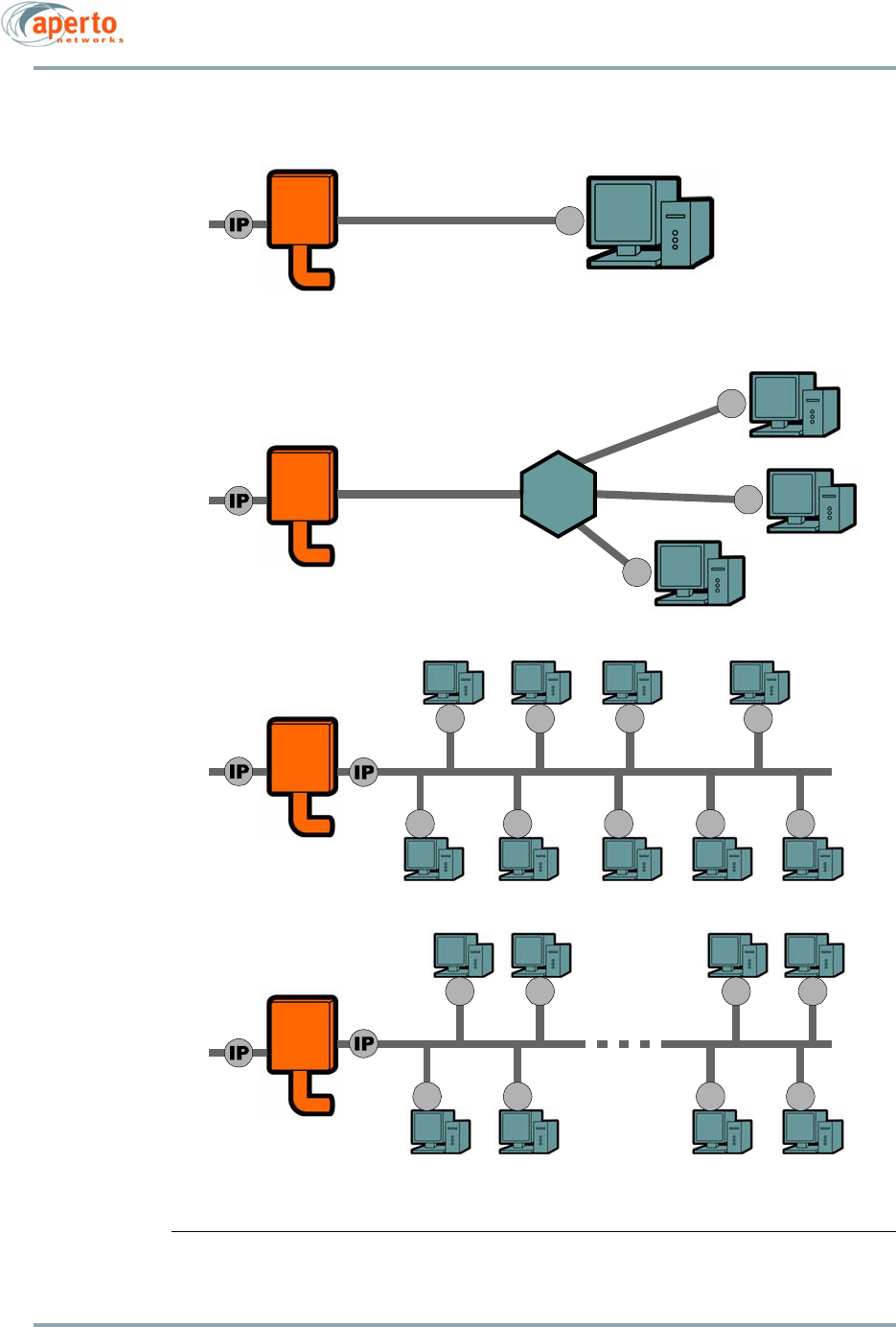
• The PacketWave 210 operates in bridging mode, supporting up to 5 hosts and 4 ser-
vice flows. It is ideal for residential subscribers.
• The PacketWave 220 operates in bridging and NAT modes, supporting up to 20 hosts
and 4 service flows. It is ideal for small office/home office (SOHO) subscribers.
• The PacketWave 230 operates in bridging, NAT, and IP routing modes, supporting
up to 254 hosts and 16 service flows. It is ideal for small and medium enterprises.
Figure 2-1 graphically illustrates the applications of the three PacketWave 200 models.
VLAN and PPPoE/PPP
All PacketWave 200 models support VLAN mode, essentially a variation of bridging mode.
In bridging mode, VLAN-tagged frames are transmitted and received transparently ( VLAN
pass-through). In VLAN mode, the PacketWave 200 functions as a bridge, but with the
ability to tag untagged frames from the Ethernet port with VLAN ID and user priority and
to strip tags from VLAN-tagged frames received at the wireless interface.
In NAT mode, the PacketWave 220 and 230 can be configured to support PPP over Ethernet
(PPPoE). These PacketWave models include a built-in PPPoE client, eliminating the need
for each host to have a PPPoE client and to originate connections by logging in.
For more about VLAN and PPPoE, see the PacketWave 1000 Base Station Unit Manual.
Chapter 2. Overview
2–2
10004880 Rev. D1
Figure 2-1 PacketWave 200 Series Operating Modes
NAT
Router
Standard
Router
Bridge
Bridge
All models
All models
PacketWave 220
& PacketWave 230
PacketWave 230
IP
IP
IP
IP
IP
IP
Hub
IP
IP
IP IP
IP
IP
IP
IP
IP
IP
IP
IP
IP
IP
IP
2–3
10004880 Rev. D1
Chapter 2. Overview
Subscriber Equipment
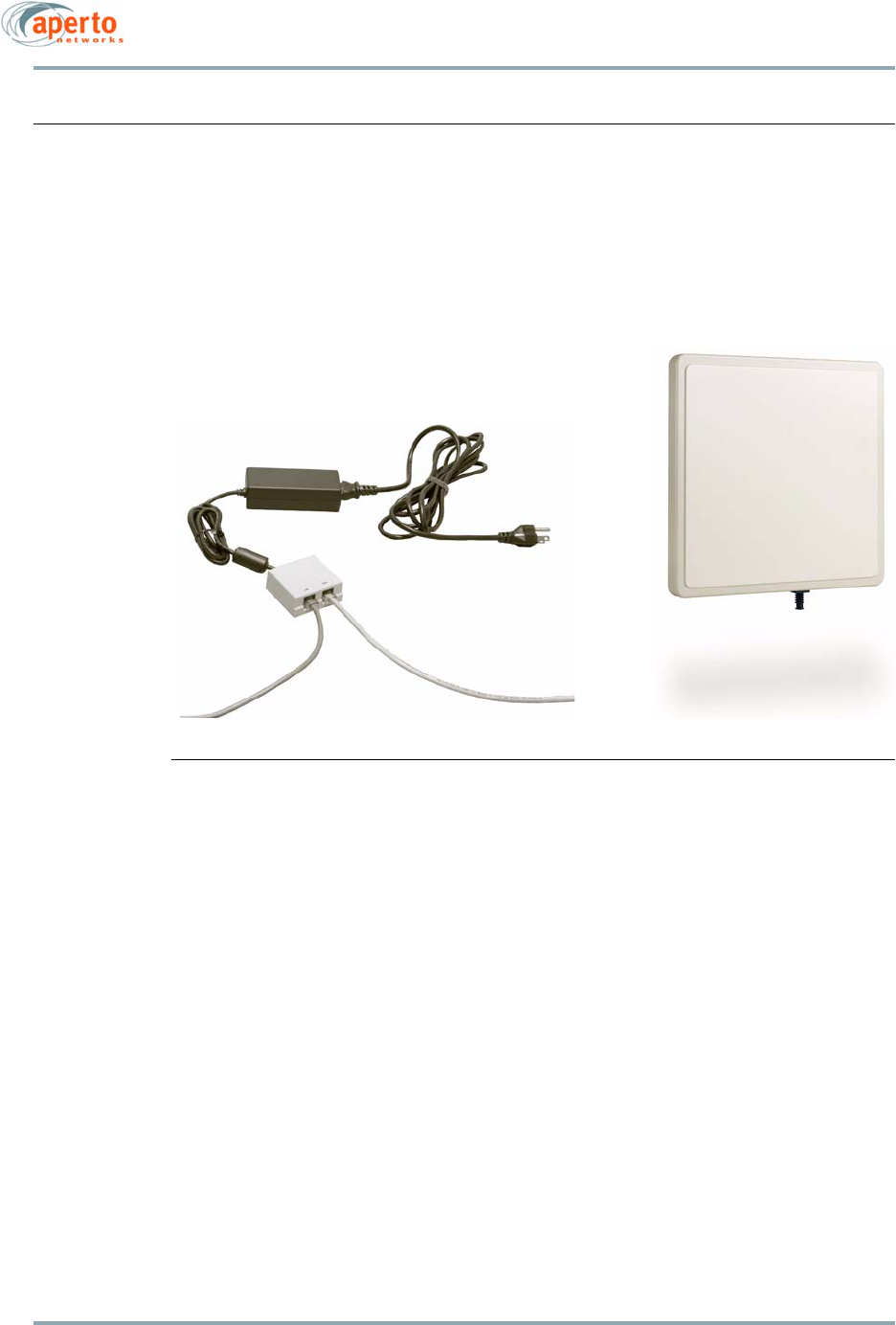
PacketWave 200 Series subscriber equipment consists of a main Outdoor Unit (ODU) and
a small indoor Interface Box, as shown in Figure 2-2.
Figure 2-2 PacketWave 200 Series Subscriber Equipment
Outdoor Unit
The outdoor portion of the subscriber equipment consists of a single unit, approximately
9 inches square, containing the radio, antenna, and bridge/router. Different versions sup-
port various frequency bands:
•2.5 GHz MMDS
•3.5 GHz FWA
•5.3 GHz
•5.8 GHz ISM
The ODU must match the frequency band employed at the base station.
ODUs mount easily on a home or office roof, under the eave, or even in a properly-situated
window. Depending on distance, a line-of-sight path may not be required for establish-
ment of a wireless link between the subscriber and the base station. PacketWave’s
OptimaLink technology minimizes the effects of obstructions in the path between the sub-
scriber’s antenna and the base station antenna.
Outdoor Unit
Interface Box
Power Supply
(ODU)

Chapter 2. Overview
2–4
10004880 Rev. D1
The ODU antennas are directional, with a beam width of 17° to 20° horizontally and verti-
cally depending on frequency. The width of this beam, combined with the width of the
base station antenna beam (90° or 60°), means that only rough alignment of the antenna
is needed for establishing a wireless link, though accurate alignment is important for max-
imum signal quality.
Automatic Frequency Selection
The PacketWave 200 Series supports Automatic Frequency Selection (AFS), which helps
to ensure optimal performance in less-than-optimal conditions. A total of up to 20 fre-
quencies within the unit’s frequency band can be selected. With AFS, when interference
degrades performance on the primary frequency, the BSU will automatically shift the link
to a frequency providing satisfactory performance using QPSK.
Indoor Unit
The Indoor Unit (IU) is a power injection box for the Aperto 200 series. It is an intelligent
device that insures power will only be injected towards the Outdoor Unit (ODU) and not to
a computer or router. The IU is marked LAN and ODU ports to avoid confusion while con-
necting the IU, ODU, and computer or router. Also, IU uses standard power-over-Ethernet
cabling and therefore is limited to a maximum of 100 meters. The amount of power
required for the long-range radios is higher. Further, IU provides 36 V at 1.11 Amps yielding
40 Watts of power. Please do not attempt to use third part power injectors with the Pack-
etWave 200 series products.
If the resistance that shows the unit connected to the ODU port is not correct, no power
will be put on the CAT-5 cable. When the power is put on the cable, the IU will display a
green LED signifying power is being transmitted. The LED is not a link status light. An
orange LED shows there is an error in the connection.
Interface Box
The Interface Box is a small, free-standing unit which can be placed virtually anywhere
within the subscriber’s premises, subject to the following basic requirements:
• The unit must have access to AC power.
• The cable run to the Outdoor Unit can be up to 100 m (330 ft) with proper cable.
See Appendix E for cable details.
The Interface Box has two RJ-45 connectors for connecting to the Outdoor Unit (ODU) and
the hub, switch, or PC on subscriber’s LAN.
NOTE: These connectors are extensions of the Ethernet port on the ODU. The
Interface Box does not regenerate Ethernet signals as an Ethernet hub does. In
2–5
10004880 Rev. D1
Chapter 2. Overview
addition, the ODU port on the Interface Box provides power to the ODU via the
Ethernet cable connecting the units.
WARNING: There is DC power on the Interface Box’s ODU port. Connecting this port to
a PC or switch will cause permanent damage to the device.
The Interface Box comes with an external power supply and power cord that plugs into a
standard AC wall plug (120 or 220 volts).
On PacketWave 100, and 200 series there is no serial interface. If the Ethernet port
of the computer or router connected to the 100 or 200 series cannot auto-negotiate
(standard practice) and requires static setting, it cannot be performed if the wireless
link is down. This rarely happens because the 100/200 will set the Ethernet interface
to theslowest possible value (10 Mbits, half-duplex). This should allow enough flexi-
bility and communication to change the static setting.
Management, Configuration, and Diagnostics
The PacketWave 200 includes a number of features which provide management,
configuration, and diagnostic functions. They range from LEDs to a Web-based graphical
user interface, and include:
• LEDs — LED indicators on the Outdoor Unit and Interface Box show status of the
LAN and wireless interfaces as well as power to the unit.
• Audio Auto-Alignment - Simplifies antenna.
• Installation Manager — This utility initializes newly-installed subscriber equipment
and allows antenna alignment for optimal wireless communication. Use of the
Installation Manager is described in Chapter 5.
• Web GUI — Each PacketWave 200 includes a graphical user interface (GUI) which
can be accessed via a standard Web browser, either directly or through the Base
Station Unit’s Web GUI. Use of the Web GUI for configuration, status, and perfor-
mance monitoring is described in Chapter 6.
• SNMP Agent — Each PacketWave 200 includes an SNMP agent which can be
accessed via a standard SNMP manager, either directly or through the Base Station
Unit’s proxy agent.
• Diagnostic Manager — This utility provides diagnostic testing of the subscriber
equipment. Use of the Diagnostic Manager is described in Appendix C.
• Command Line Interface — For basic diagnostics, a limited command line interface
(CLI) to the PacketWave 200 can be accessed via telnet. Use of the CLI is described
in Appendix D.

Chapter 2. Overview
2–6
10004880 Rev. D1
SU Configuration
SU configuration can be done in server mode or in local mode:
• In local mode, the SU’s configuration is performed using the Aperto Installation
Manager (AIM). No configuration file is downloaded from the BSU’s TFTP server.
• In server mode, subscriber equipment is provisioned using the WaveCenter Config-
uration Manager, as described in the
PacketWave 1000 Base Station Unit Installa-
tion, Configuration, and Operation
manual. On boot-up, after getting address and
file information from its assigned DHCP server, the PacketWave 200 downloads its
configuration file from the base station’s TFTP server.
PacketWave 200 should be appropriately be configured in Server mode. They receive their
IP address and configuration information from a DHCP server. DHCP entries should be
reserved to the MAC address of the deployed/provisioned Aperto equipment. PacketWave
200 should be configured with infinite leases. This is highly appropriate since you never
want to give this IP address to another device in the network.
Some configuration of the PacketWave 200 can be performed via the Web GUI and SNMP.
If desired, these configuration changes can be made permanent by uploading them to the
SU configuration file on the TFTP server. (If configuration changes are made via the Web
GUI or SNMP but not uploaded, they will be lost when the PacketWave 200 is reset or re-
powered.) Uploading configuration changes made via the Web GUI or SNMP is a conve-
nient way to modify the configuration file of an in-service PacketWave 200.
Configuration uploads from the Web GUI and SNMP require that the TFTP server be
configured to accept uploads.
NOTE: Advanced Installation Manager (AIM) will allow the installer to configure
a Subscriber Unit (SU) in local mode by providing appropriate IP addresses and con-
figuration parameters. It always uses the default configuration file for the unit.
Aperto highly suggests only using server mode for the Subscriber Unit.
Built-In Server, Client, Agent, and Router Functions
Servers, agent/client, and router functions are built into PacketWave 200:
• DHCP Client — All PacketWave Series 200 models include a Dynamic Host
Configuration Protocol (DHCP) client for local address management by the Base
Station Unit’s assigned DHCP server.
• DHCP Server — PacketWave 220 and 230 models include a Dynamic Host
Configuration Protocol (DHCP) server for local address management.
• NAT Server — PacketWave 220 and 230 models include a built-in NAT (Network
Address Translation) server.
• IP Router — PacketWave 230 models include a built-in IP router.
• SNMP Agent — All PacketWave Series 200 models include an SNMP agent for inte-
gration of the PacketWave network into an SNMP management system.
2–7
10004880 Rev. D1
Chapter 2. Overview
• PPPoE Client — PacketWave 220 and 230 models include a built-in PPPoE (PPP over
Ethernet) server.
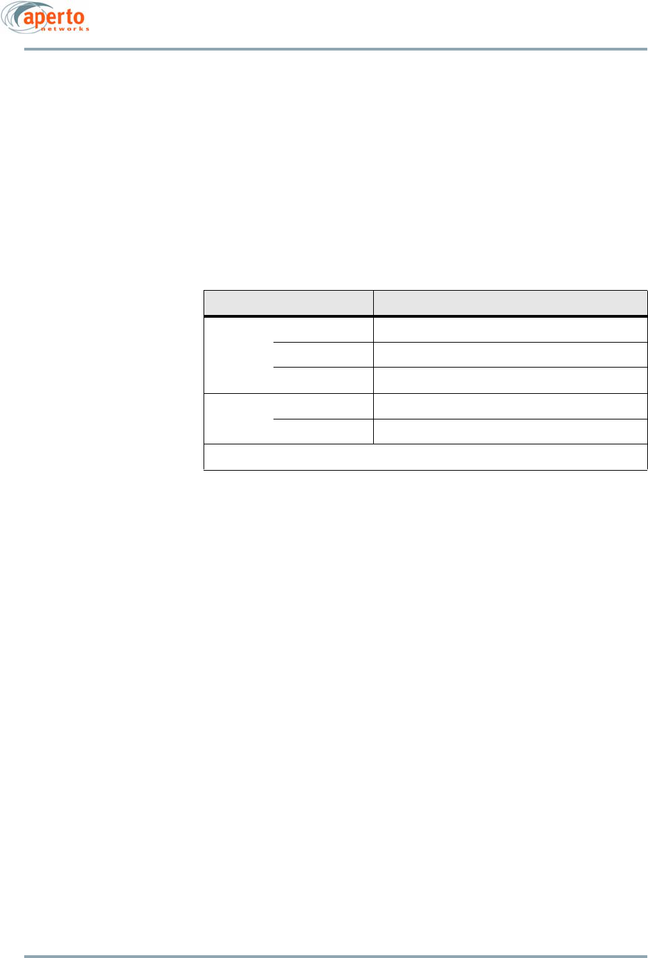
PacketWave 200 LEDs
The LEDs on the Outdoor Unit and Interface Box provide operational information as
described in Table 2-A.
SNMP
Each PacketWave 200 includes an SNMP agent supporting the following MIBs:
• SNMP MIB (RFC 1157)
• MIB II (RFC 1213)
• Aperto private MIB
The complete MIBs are provided on the PacketWave CD, and are available on the Aperto
Web site,
www.apertonet.com
.
SNMP can be used to read configuration, status, and performance data from Subscriber
Units. In addition, SNMP can be used to change some configuration parameters (those
which can be changed via the Web GUI), and to upload the configuration changes to the
TFTP server (if the TFTP server is configured to accept uploads).
The SNMP agents support trap reporting. Trap-reporting parameters can be specified via
the Configuration Manager and the Web GUI as well as via SNMP.
Table 2-A PacketWave 200 LEDs
LED Indications
Outdoor
Unit
Left Wireless Tx: Blinks on Wireless transmit activity.
Middle Wireless Rx: Blinks on Wireless receive activity.
Right On when Ethernet link is up; Off when it is down.
Interface
Box
ODU Port, left On when the Interface Box is powered on.
ODU Port, Right On when power is provided to the Outdoor Unit.
LEDs for the LAN port on the Interface Box are always off.

Chapter 2. Overview
2–8
10004880 Rev. D1
Event Reporting
The PacketWave 200 offers several means of reporting subscriber equipment events:
• E-mail messages — The PacketWave 200 can be configured (via the Configuration
Manager, the Web GUI, or SNMP) to report events via e-mail to specified addresses.
• SNMP traps — The PacketWave 200 SNMP agent supports trap reporting. Trap-
reporting parameters can be specified via the WaveCenter Configuration Manager,
the Web GUI, or SNMP.
• Syslog — The PacketWave 200 supports logging of event messages to a designated
server according to the Syslog protocol. If Syslog is employed, the Syslog server
must be identified in the Subscriber Unit configuration file created using the
WaveCenter Configuration Manager.
Use of Syslog is strongly recommended as a means of providing a record of
system events for performance management and troubleshooting.
• Event log — A historical event log can be displayed on request via the Web GUI.
For information about specific PacketWave 200 events which can be reported, see
Appendix B.

3–1
10004880 Rev. D1
3
Site Planning
There are three basic site-planning issues which must be decided before you begin instal-
lation:
• Location of the Interface Box.
• Location and mounting method of the Outdoor Unit.
• Cable path between the Interface Box and the Outdoor Unit.
Location of the Interface Box
Typically, the Interface Box is located near the subscribers hub or computer. However, the
Ethernet cable to the local computer or hub can be up to 100 m (330 ft) in length.
Location of the Outdoor Unit (ODU)
For optimal wireless channel performance, it is advantageous to locate the PacketWave
200 Outdoor Unit where it has the least-obstructed path to the base station antenna. If a
line-of-site path is available, locate the Outdoor Unit where the path is least likely to be
affected by such obstructions as blowing branches, seasonally changing foliage, etc. If a
clear line-of-site path is not available, choose a path that minimizes obstructions.
Fine-tuning of the antenna alignment is performed using the Aperto Installation Man-
ager utility, as described in Chapter 4 of this manual.
Other factors to consider when choosing a location for the Outdoor Unit include:
• Distance to the Interface Box — Locate the Outdoor Unit so that cables to the Inter-
face Box will be within the maximum cable length limit as described in Table 3-A.
• Cable routing — Consider how cables from the Outdoor Unit will enter the building.
Chapter 3. Site Planning
3–2
10004880 Rev. D1
• Accessibility — If possible, choose a location that is relatively accessible, which will
simplify installation and any adjustment or repair in the future.
• Mounting method — The Outdoor Unit’s standard mounting bracket supports
mounting on a pole that is 1.5 inches (3.8 cm) or 2 inches (5.1 cm) in diameter. For
other mounting options (under an eave or on a chimney, for example), mounting
hardware may be adapted or replaced as necessary. Any alternate mounting
method should allow adequate adjusting of the antenna direction, both horizon-
tally and vertically.
Cables and Cable Path
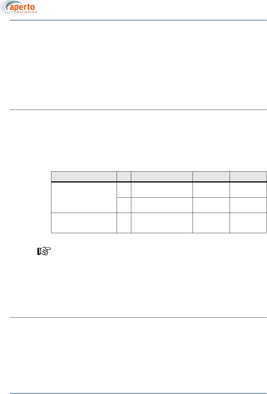
For PacketWave 200 installation, you will need the cables indicated in Table 3-A. See
Appendix for additional details about the cable from the Interface Box to the ODU.
Specific models of cable are listed in a document titled Cables for PacketWave Prod-
ucts, included on the PacketWave CD that accompanies the equipment.
Choose the path along which the cable will run between the Interface Box and the Outdoor
Unit. Carefully consider both the outdoor and indoor portions of the cable run. Decide how
the cable run will be secured, how it will enter the building, and whether it will include
wall jacks. Consider all local building codes and standard construction practices when
planning the cable path.
Subscriber LAN/Computer
If the PacketWave 200 is functioning in NAT mode, addresses on the local subnet (i.e.,
LAN) will not be visible beyond the subscriber’s subnet. The PacketWave 200 can become
a DHCP server for hosts on the subscriber’s subnet. In addition, in the default setting, the
PacketWave 200’s DHCP server will use the DNS server address supplied by the system’s
DHCP server to resolve network addresses.
Table 3-A Subscriber Site Cable Requirements
Connection Qty Cable Type Max. Length Connectors
Interface Box to ODU 1 Shielded outdoor-rated Cat
5
50 m (165 ft) RJ45 male (2)
Shielded outdoor-rated Cat
5E
100 m (330 ft) RJ45 male (2)
Ethernet to Computer/Hub 1 Cat 5 Ethernet cable:
crossover for computer,
straight-through for hub
Per cable spec-
ifications
RJ45 male (2)

4–1
10004880 Rev. D1
4
Subscriber Equipment Installation
Installing the PacketWave 200 Series Subscriber Equipment consists of the following
steps:
1. Determining the locations for the Interface Box and Outdoor Unit (ODU).
2. Mounting and grounding the ODU.
3. Installing the Ethernet cable between the Interface Box and ODU.
4. Optimizing the direction of the antenna using the audio auto-alignment mode.
5. Connecting the Interface Box to the subscriber’s computer or LAN, and to AC power.
6. Configuring the subscriber’s PC or LAN.
7. If the audio auto-alignment mode was not used or was not successful, using the
Aperto Installation Manager utility to optimize the direction of the antenna.
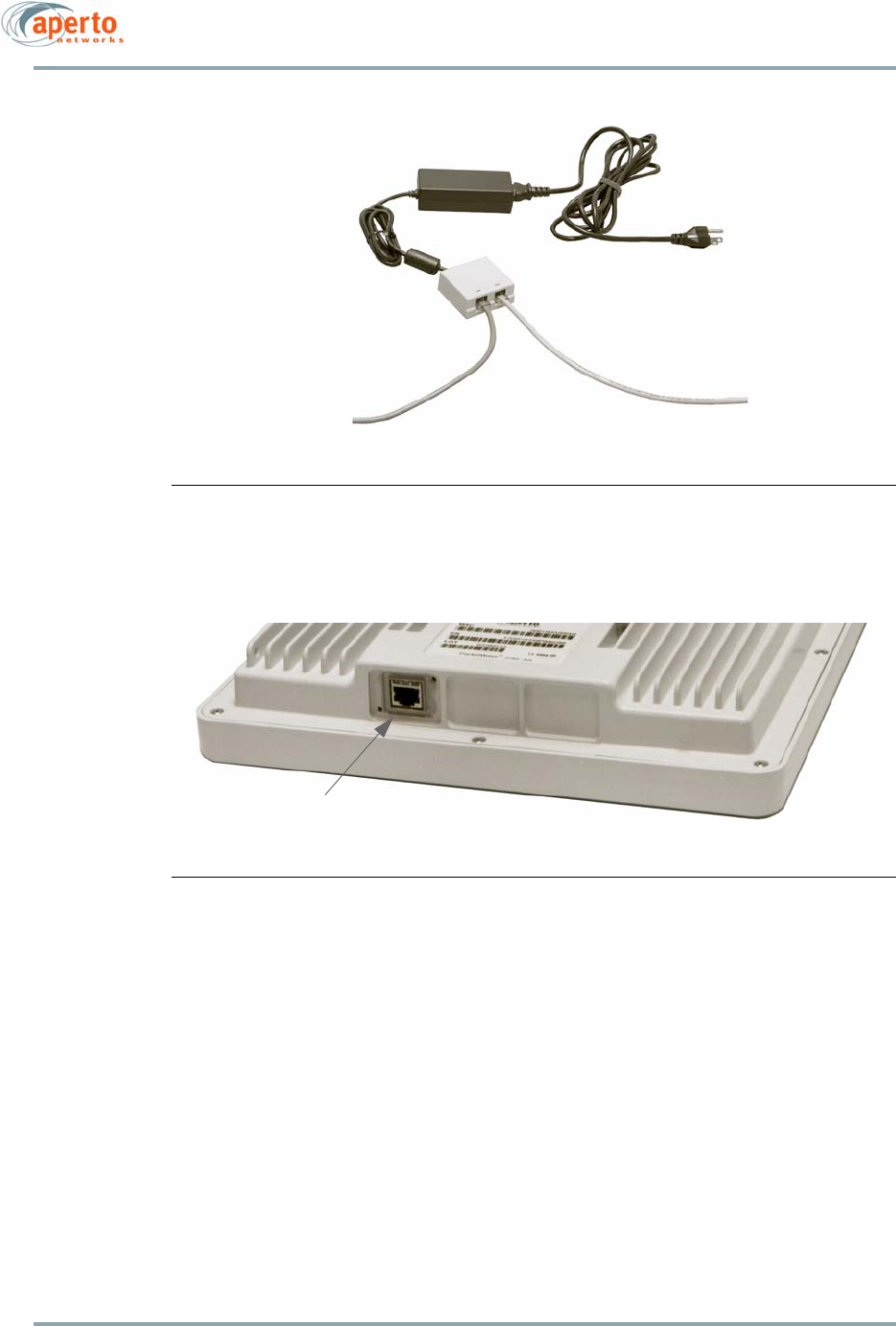
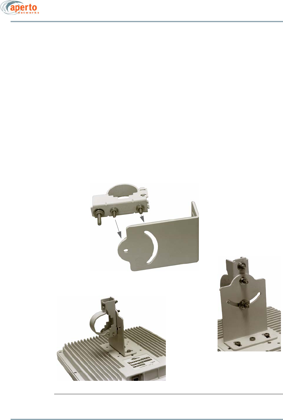
Connectors on the Interface Box and Outdoor Unit are shown in Figure 4-1 and Figure 4-2,
respectively.
NOTE: Connectors and/or markings on some units may be slightly different in
appearance from those shown in the figures.
Chapter 4. Subscriber Equipment Installation
4–2
10004880 Rev. D1
Figure 4-1 Interface Box Connections
Figure 4-2 Outdoor Unit Connector
Interface Box
Power Supply
to Outdoor Unit
to AC Wall Socket
to PC or Hub/Switch
LAN Port
ODU Port
Ethernet/Power Connector

4–3
10004880 Rev. D1
Chapter 4. Subscriber Equipment Installation
Installation Requirements
You will need the following tools and supplies when installing the PacketWave 200:
• Drill (for cable entry through walls, etc.)
• Phillips screwdriver
•Wrench (7/16 inch)
• Cabling tools
• Cable tester (capable of testing 10Base-T and EIA/TIA 568B)
• Cable ties, staples, or clamps for dressing cables
• Silicone sealant
You will also need the following cables and connectors:
• Shielded Cat 5 or Cat 5E cable (outdoor rated), long enough to run between the
Interface Box and the Outdoor Unit, with rubber connector boot and two shielded
RJ45 male connectors. See Appendix for cable details.
• Ethernet cable with RJ45 male connectors (straight-through for connection to hub,
or crossover for connection to computer).
You may also need a PC (laptop highly recommended) with the Aperto Installation
Manager utility installed. The Installation Manager can be used for configuration and to
fine-tune the alignment of the antenna (Outdoor Unit) for optimal communication with the
base station. If the PacketWave 200 is pre-provisioned, however, the audio auto-align-
ment mode can be used for antenna alignment, and a PC connection will not be required
for installation.
Mounting the Outdoor Unit
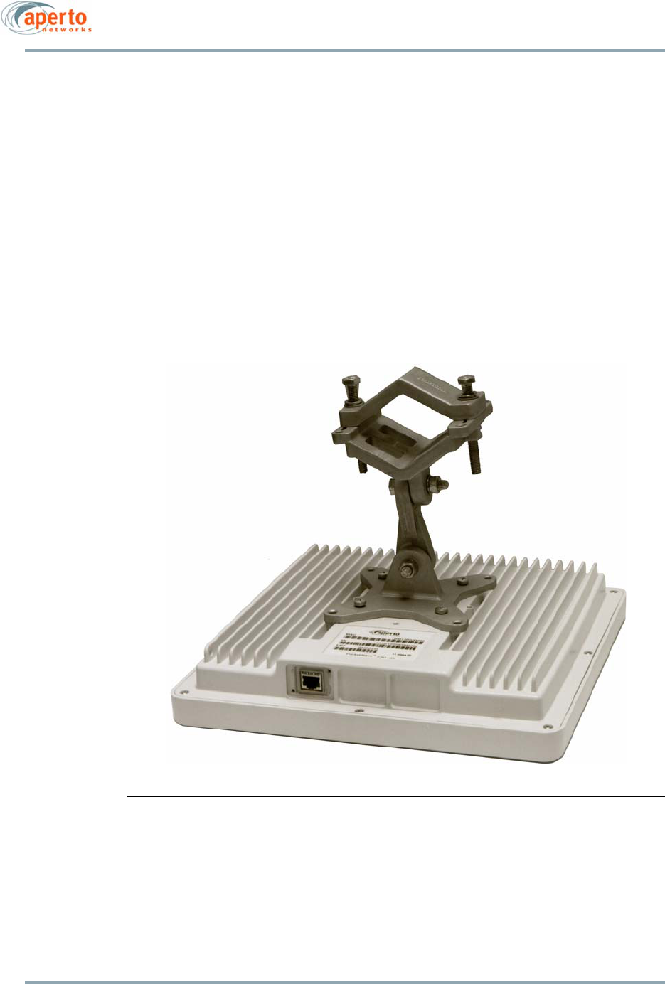
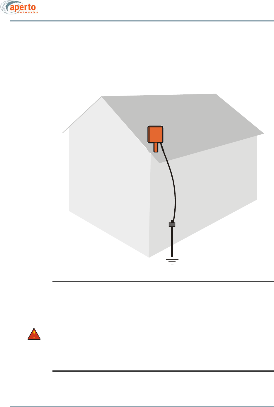
The Outdoor Unit (ODU) includes a rear-mounted bracket as shown in Figure 4-3. This
standard mounting bracket allows the ODU to be mounted on a pole or antenna mast with
a diameter of 1.5 or 2 inches (3.8 or 5.1 cm). Aperto also offers an alternate bracket, as
illustrated in Figure 4-4.
Other mounting options, such as under an eave or in a window, can also be employed. In
such cases, appropriate mounting hardware must be obtained.
WARNING: Outdoor installation procedures should be performed by qualified profes-
sionals following all safety and other requirements and acting in accor-
dance with standard practices and procedures. Failure to meet safety
requirements and/or non-standard practices and procedures could result
in personal injury and/or damage to equipment.
Chapter 4. Subscriber Equipment Installation
4–4
10004880 Rev. D1
To mount an Outdoor Unit on a pole using the standard bracket shown in Figure 4-3:
1. Locate the mounting holes for the standard bracket on the back of the ODU. There
are two sets of holes, allowing the mounting bracket to be oriented vertically or at
45 degrees. Choose the best orientation, making sure the RJ45 connector will be at
the bottom of the ODU when it is mounted.
2. Attach the L-bracket to the back of the ODU using the three screws provided.
3. Remove the bolt that holds the clamp closed.
4. Position the clamp around the pole in the desired location. Install and tighten the
clamp bolt to secure the clamp to the pole.
5. Position the ODU with attached L-bracket so that two bracket bolts on the clamp fit
through the mounting hole and slot on the L-bracket. Using the washers and nuts
provided, secure the L-bracket to the clamp.
6. Adjust the azimuth and elevation orientation of the radio/antenna as necessary by
loosening the appropriate nuts, repositioning the ODU, and tightening the nuts.
Figure 4-3 Standard ODU Mounting Bracket
L-Bracket
Pole Clamp
4–5
10004880 Rev. D1
Chapter 4. Subscriber Equipment Installation
To mount an Outdoor Unit on a pole using the alternate bracket shown in Figure 4-4:
1. Locate the appropriate mounting holes for the alternate bracket on the back of the
ODU.
2. Attach the mounting bracket to the ODU using the four screws provided.
3. Remove the two bolts that hold the pole clamp closed.
4. Position the clamp around the pole in the desired location. Install and tighten the
clamp bolts to secure the clamp to the pole.
5. Adjust the azimuth and elevation orientation of the radio/antenna as necessary by
loosening the appropriate nuts, repositioning the ODU, and tightening the nuts.
Figure 4-4 Alternate ODU Mounting Bracket
Chapter 4. Subscriber Equipment Installation
4–6
10004880 Rev. D1
Grounding the Outdoor Unit
Grounding of the outdoor radio/antenna is an essential part of the installation process. A
proper grounding circuit is illustrated in Figure 4-5.
Figure 4-5 Grounding the Outdoor Unit
WARNING: Lightning protection is recommended for subscriber equipment. Instruc-
tions and an example are contained in the document titled
Surge Protec-
tion for PacketWave Products
, included on the PacketWave CD that
accompanies the equipment. (If the CD or document were not provided,
contact Aperto Customer Service.) Lightning damage is not covered by
the product warranty.
Connection to
Outdoor Unit
Ground Lug
Grounding Conductor
(NEC Section 810-21)
Grounding Clamp
4–7
10004880 Rev. D1
Chapter 4. Subscriber Equipment Installation
To properly ground the Outdoor Unit:
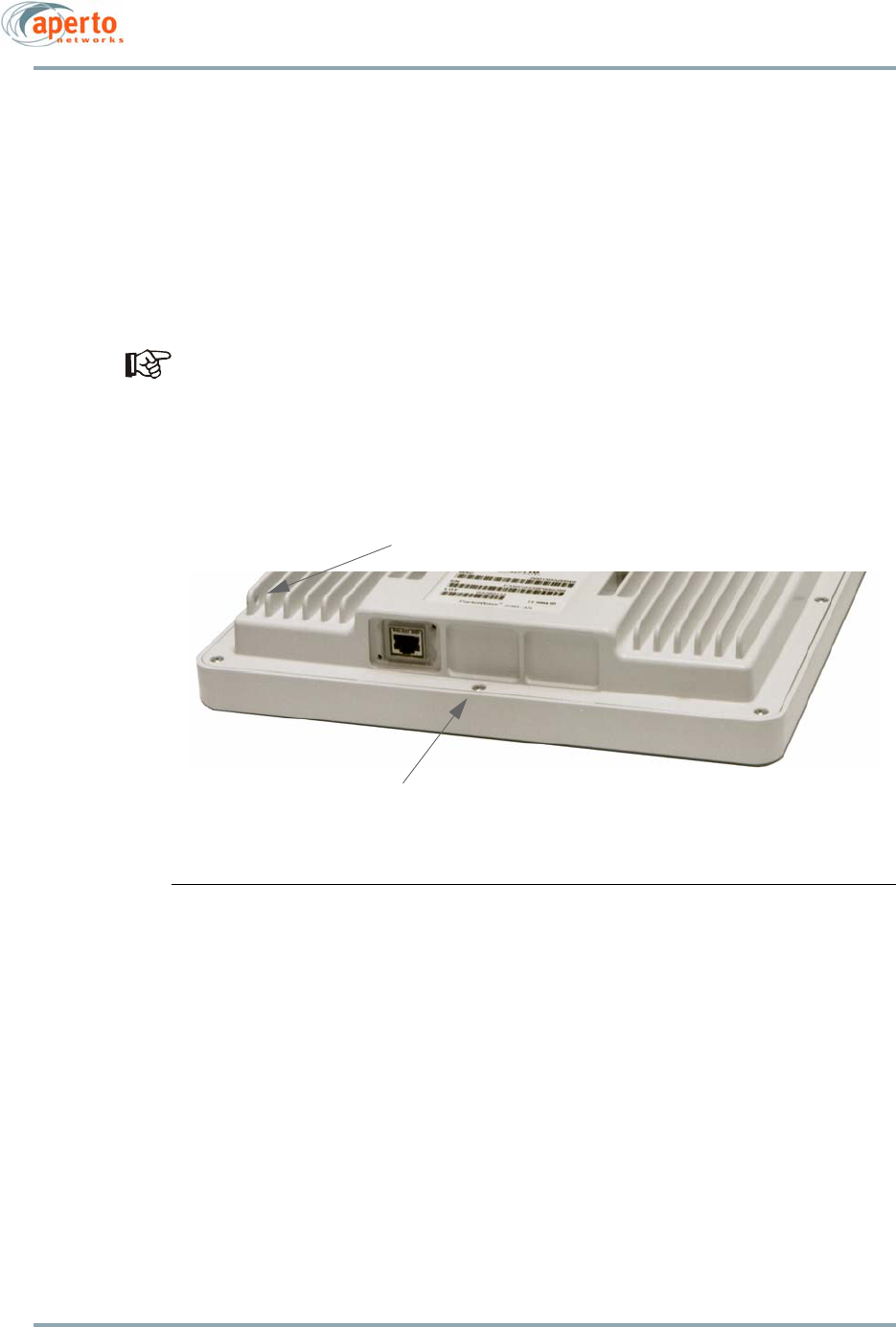
1. Locate the grounding lug on the ODU, as illustrated in Figure 4-6.
2. Provide a proper grounding conductor (NEC Section 810-21) long enough to reach
from the Outdoor Unit to the earth ground.
3. Attach one end of the conductor to the lug on the ODU.
4. Connect the other end of the grounding conductor to an appropriate earth ground
using a grounding clamp.
If you install a grounding electrode separate from the power service grounding elec-
trode system, connect the separate electrode to the grounding system in accordance
with the National Electrical Code (NEC) and local electrical codes.
Figure 4-6 Location of Grounding Lug on Outdoor Unit
Grounding Lug Location —
Attach Electrode to Lug
Hole for Cable Tie

Chapter 4. Subscriber Equipment Installation
4–8
10004880 Rev. D1
Positioning the Interface Box
Position the Interface Box in a suitable location (typically an out-of-the-way location near
the subscriber’s computer or LAN hub/switch) within reach of an AC wall socket.
Connecting the ODU to the Interface Box
A single cable connects the Outdoor Unit to the Interface Box, providing an Ethernet link
as well as power from the Interface Box to the ODU. The cable should be shielded outdoor-
rated Cat 5 or Cat 5E with an RJ45 male connector (plug) at each end, and can be up to 50
m (165 ft) in length with Cat 5 cable, or up to 100 m (330 ft) with Cat 5E. See Appendix for
cable details.
NOTE: For outdoor-to-indoor connections, the order of the steps in the installa-
tion procedure will vary depending on a number of factors, including site partic-
ulars and installers’ preferred practice. For example, in some cases it may be best
to run unterminated cable and then attach connectors; in others it may be more
efficient to attach one or both connectors to the cable before running it, or to use
a pre-assembled cable. Also, cable dressing at various locations may be best per-
formed at different points in the procedure. Therefore, the procedures given for
these connections should be taken as a list of necessary steps and a suggested
order, and modified as appropriate for your particular circumstances.
1. Obtain an appropriate length of cable, and run it from the Interface Box to the Out-
door Unit. Include a service/drip loop as appropriate.
2. Place the supplied rubber boot over the outdoor end of the cable.
3. Install a shielded RJ45 male connector on each end of the cable, making sure to
connect the cable shield to the RJ45 ground shell.
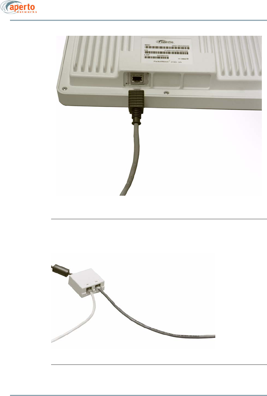
4. Plug the cable into the RJ45 socket on the Outdoor Unit as shown in Figure 4-7.
5. Make sure the boot is properly seated in the mating flange cutout. The boot should
be flush with the radio housing. Secure the boot to the radio housing with the
screws provided. Secure the exit point of the cable from the boot with a cable tie.
6. Dress the conductor using a cable tie through the hole illustrated in Figure 4-6,
ensuring that the cable does not hang unsupported from the connector.
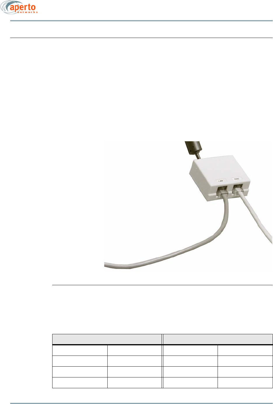
7. Attach the cable to the ODU connector on the Interface Box as shown in Figure 4-8.
WARNING: There is DC power on the Interface Box’s ODU port. Connecting this port to
a PC or switch will cause permanent damage to the device.
8. Seal the entry of the cable to the building as appropriate.
4–9
10004880 Rev. D1
Chapter 4. Subscriber Equipment Installation
Figure 4-7 Connection to the Outdoor Unit
Figure 4-8 Interface Box Connection from Outdoor Unit
To Interface Box
To Outdoor Unit
ODU Port
Chapter 4. Subscriber Equipment Installation
4–10
10004880 Rev. D1
Connecting to the Local Computer or LAN
To connect the Interface Box to the subscriber’s computer(s):
1. Provide an appropriate Cat 5 Ethernet cable with an RJ45 male connector at each
end. Use a straight-through cable for connection to a hub or switch. Use a crossover
cable for connection directly to a computer. (See Table 4-A for pinouts.)
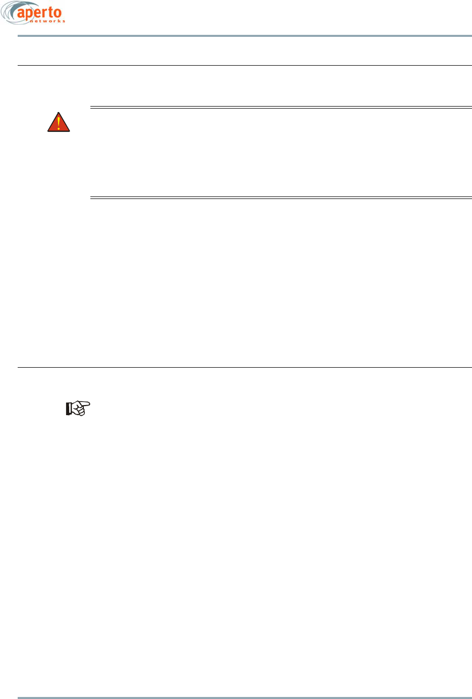
2. Plug one end of the Ethernet cable into the RJ45 socket labeled LAN on the Interface
Box, as illustrated in Figure 4-9.
3. Plug the other end of the Ethernet cable into the socket on the local hub, switch,
or computer.
Figure 4-9 Subscriber Ethernet Connection
Table 4-A Ethernet Cable Pinouts
Straight Cable (to Hub or Router) Crossover Cable (to PC)
Pin 1: Tx+ Pin 1: Rc+ Pin 1: Rc+ Pin 3: Tx+
Pin 2: Tx- Pin 2: Rc- Pin 2: Rc- Pin 6: Tx
Pin 3: Rc+ Pin 3: Tx+ Pin 3: Tx+ Pin 1: Rc+
Pin 6: Rc- Pin 6: Tx- Pin 6: Tx- Pin 2: Rc-
To computer or LAN
LAN port
4–11
10004880 Rev. D1
Chapter 4. Subscriber Equipment Installation
Powering Up the PacketWave 200
WARNING: For the PacketWave 200, use an outlet that contains surge protection and
ground fault protection, or use a surge protection device. This will protect
the PacketWave 200 and equipment connected to it from damage result-
ing from AC current surges, lightning, etc. For complete protection, all
connections to the PacketWave 200 should be connected to a surge pro-
tection device. To ensure the best signal, use surge protectors designed
for the specific application.
To apply power to the PacketWave 200:
1. Plug the power cord into the connector on the transformer connector to the Inter-
face Box.
2. Plug the power cord into a surge-protected AC outlet.
The PacketWave 200 does not have an on/off switch; to turn the unit off, disconnect power
at the power outlet.
NOTE: The ODU receives power from the Interface Box via the Ethernet cable.
Aligning the Antenna Using Audio Auto-Alignment Mode
For the audio auto-alignment mode to function, the PacketWave 200 must be pre-
provisioned prior to installation using the Aperto Installation Manager (AIM) in Provi-
sion mode, as described in Chapter 5. If preconfiguration has not been performed,
use the AIM for antenna alignment as detailed in Chapter 5
When power is applied to a pre-configured PacketWave 200, the ODU will begin slowly beep-
ing. The beep is an audio indication of the strength of the signal received from the base sta-
tion. As reception gets stronger (within the range from -50 dBm to -100 dBm), beeping
increase in pitch and frequency, becoming a continuous tone when the signal is optimal.
To optimize antenna alignment using the audio auto-alignment mode:
1. Adjust the position of the ODU for the highest pitch and frequency of the beeping,
ideally finding a position which results in a continuous tone. Secure the ODU in
that position.
2. When the ODU receives a continuously strong signal for one minute (specifically,
when the signal-to-noise ratio is higher than 16 dB and the signal strength is greater
than -88 dB without varying by more than 2 dB for one minute), the PacketWave 200
will become operational with an audio tone similar to a telephone ringing.
3. If such a signal is not obtained, the audio signal will continue until power is removed,
and the PacketWave 200 will not become operational. Antenna alignment will need
to be performed using the Aperto Installation Manager as described in Chapter 5.

Chapter 4. Subscriber Equipment Installation
4–12
10004880 Rev. D1
Connection to the PacketWave Network
When the PacketWave 200 goes operational at the end of the antenna alignment, it per-
forms an initialization procedure that brings it up as part of the PacketWave network.
During this procedure:
• The PacketWave 200 requests an IP address from the system’s DHCP server. (The
DHCP request is passed along by the BSU’s DHCP relay agent.)
• The DHCP server responds with the IP address and other information, including the
name of the PacketWave 200’s configuration file. The Base Station Unit and the
PacketWave 200 both learn the new IP address.
• The PacketWave 200 downloads its configuration file (as previously created using
the WaveCenter Configuration Manager) from the TFTP server.
NOTE: For information about the WaveCenter Configuration Manager software,
see the PacketWave 1000 Base Station Unit Installation, Configuration, and Oper-
ation manual.
• The PacketWave 200 configures itself according to the received configuration file
and activates for subscriber traffic.
• If the PacketWave 200 is functioning in NAT mode, the IP addresses of its attached
computers are obtained from the PacketWave 200’s internal DHCP server.
Setting Up the Local Computer(s)
Whether the subscriber’s computers are connected to a Subscriber Unit functioning in
bridge or NAT mode, each host needs an IP address. The simplest solution is to configure
each computer to obtain its IP address using DHCP. It is also possible to manually enter
the IP addresses. For larger subscriber LANs, a local DHCP server may be preferable.

5–1
10004880 Rev. D1
5
The PacketWave AIM
This chapter provides instructions for using the Aperto Installation Manager (AIM) utility.
The AIM can be used to perform any of the following functions:
• Initially configure the PacketWave 200 and optimize antenna alignment.
• Re-align the antenna of a previously-installed PacketWave 200.
• View wireless link status.
• Perform ping and throughput tests of the wireless link between the PacketWave
200 and the base station.
• Pre-provision (preconfigure) a PacketWave 200 for later installation using the audio
auto-alignment procedure.
Aperto products have adaptive modulation and error correction. The system starts
with the highest error correction and the lowest throughput modulation. As data is
transferred without error, the system will automatically adjust. It will take about 1 Mbit
of data transfer to achieve the maximum throughput.
AIM automatically transfers data following antenna alignment and reports the actual
throughput values attained which will be less than actual since the system is adjust-
ing for the best throughput values.
Installing the AIM Software on the PC
To load the Aperto Installation Manager (AIM) software onto the computer to be used in
the procedures described in this chapter:
1. Obtain the PacketWave CD distributed with your PacketWave Series 200 equip-
ment, which includes the PacketWave Aperto Installation Manager (AIM) software
plus Java software from SUN Microsystems.

Chapter 5. The PacketWave AIM
5–2
10004880 Rev. D1
2. If the Java Runtime Environment is not present on the PC, install it from the
PacketWave CD (bsu/Software/Application/Support directory) or the java.sun.com
web site.
3. Install the Aperto Installation Manager (AIM) software by running the file
setup.exe
from the /Software/Application/ApertoInstallationManager/<OS> directory of the
PacketWave CD (where <OS> is the operating system being used, such as win32). At
the end of this installation, an AIM icon will be placed on the Windows desktop.
Connecting to the PacketWave 200
Connect the computer on which the Aperto Installation Manager (AIM) is loaded:
1. Ensure that the Interface Box is connected to the Outdoor Unit as described under
Connecting the ODU to the Interface Box on page 4-8.
2. Connect the computer to the Interface Box LAN port using a crossover Ethernet cable.
NOTE: Aperto recommends a laptop PC with 256 MB RAM, 10 GB disk drive, Pen-
tium processor, and Ethernet LAN connection. Systems as small as 128 MB RAM
and a 386 processor have been used, but their performance is not satisfactory.
3. Ensure that there is only one active Ethernet interface on the computer. (If there are
multiple active Ethernet interfaces, the AIM cannot determine which to use.)
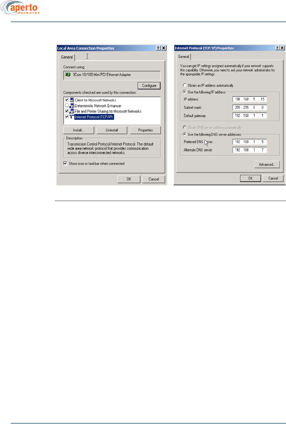
4. Ensure that the computer has a fixed IP address, and not one set by a DHCP server.
Figure 5-1 gives an example of setting a fixed IP address on Windows 2000; be sure
to select Use the following IP address. It does not matter what IP address, network
mask, and gateway are used.
5–3
10004880 Rev. D1
Chapter 5. The PacketWave AIM
Figure 5-1 Windows 2000 IP Address Setting
Chapter 5. The PacketWave AIM
5–4
10004880 Rev. D1
Using the Aperto Installation Manager
The perform any of the AIM functions, use the following procedure:
1. Connect a PC with AIM software installed to the PacketWave 200 as described in
the previous sections of this chapter.
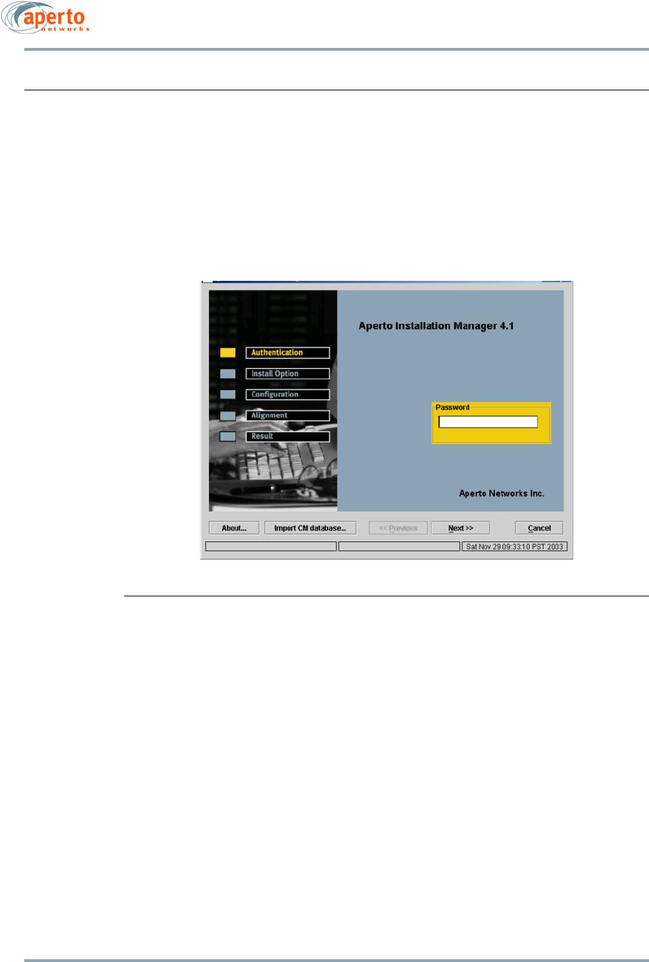
2. Double-click on the Aperto Installation Manager icon on the PC’s desktop. This will
cause the Authentication window to be displayed, as shown in Figure 5-2. Note the
buttons at the bottom of the window.
Figure 5-2 AIM Authentication Window
3. Enter the AIM password. The default is isp.
4. Click on the Next>> button at the bottom of the window. The AIM will begin commu-
nications with the PacketWave 200.
NOTE: You will get an error message if the AIM cannot establish a connection
to the PacketWave 200. Verify that you are using a crossover cable, that the
PacketWave 200 is receiving power, that the computer has just one Ethernet
interface enabled, and that it is properly configured with a fixed IP address. As
with most windows applications, double-double clicking on buttons which are
single action, will cause two occurences of the same request. This is true of the
next buttin in AIM. When the next buttin is double-clicked on the screen request-
ing the password, two tasks do the password checking. In completing with one
another, the process does not complete successfully and the error, “too many
errors” is displayed. Be Patient and single click on the next button. It will take a
few seconds to retrieve teh password from the Subscriber init and verify it.
5–5
10004880 Rev. D1
Chapter 5. The PacketWave AIM
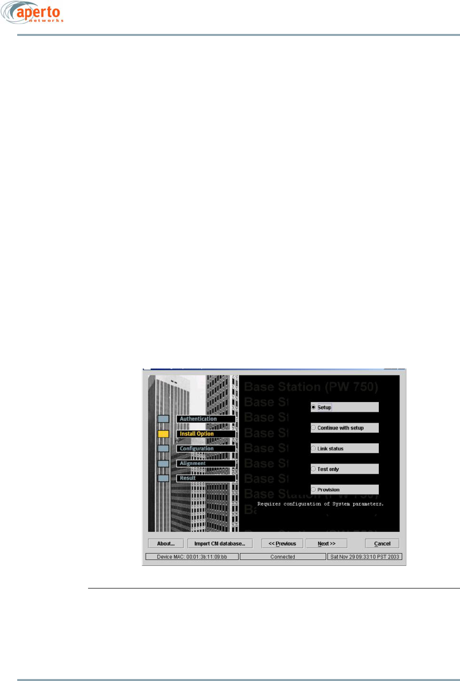
5. The Installation Option Window will be displayed, as shown in Figure 5-3. This win-
dow presents five AIM modes:
•Setup provides the complete AIM functionality: basic configuration, antenna
alignment, and throughput testing. To use this option, proceed to the next
section, Basic Configuration.
•Continue with Setup is used for antenna alignment when basic configuration
has already been completed. (Use this option if antenna alignment was not
successfully completed for a preconfigured PacketWave 200.) To use this
mode, follow the instructions under Re-aligning the Antenna (Continue with
Setup Mode) on page 5-15.
•Link Status displays graphs of the status of the wireless link. To use this
mode, follow the instructions under Viewing Status of the Wireless Link (Link
Status Mode) on page 5-16.
• Test only provides direct access to the ping and throughput tests. To use this
mode, follow the instructions under Running a Non-Destructive Test (Test
Mode) on page 5-18.
• Provision provides access to the basic configuration without proceeding to
antenna alignment; it allows pre-provisioning of the unit prior to installation,
and enables the audio auto-alignment feature described in Chapter 4. To use
this mode, follow the instructions under Pre-provisioning a PW200 for Later
Installation (Provision Mode) on page 5-19.
Figure 5-3 Install Option Window
Chapter 5. The PacketWave AIM
5–6
10004880 Rev. D1
Downloading the BSU’s IM.DAT File
When BSU configuration is performed using the Configuration Manager (CM), the IM.DAT
database file is generated. This file records basic parameters for all configured BSUs:
• BSU config file name
•BSU name
•Sector name
• Channel width
• Channel frequency
•Broadcast polarization
•BSU diversity
•SR ratio
•Frequency band
The Configuration Manager has an option to copy the IM.DAT file to a diskette.
The Installation Manager allows the IM.DAT file to be downloaded from the computer to
the PacketWave 200. The PacketWave 200 will then load all of its configuration parame-
ters automatically from the IM.DAT file once the SU’s BSU and sector are selected.
To download the IM.DAT file to the PacketWave 200:
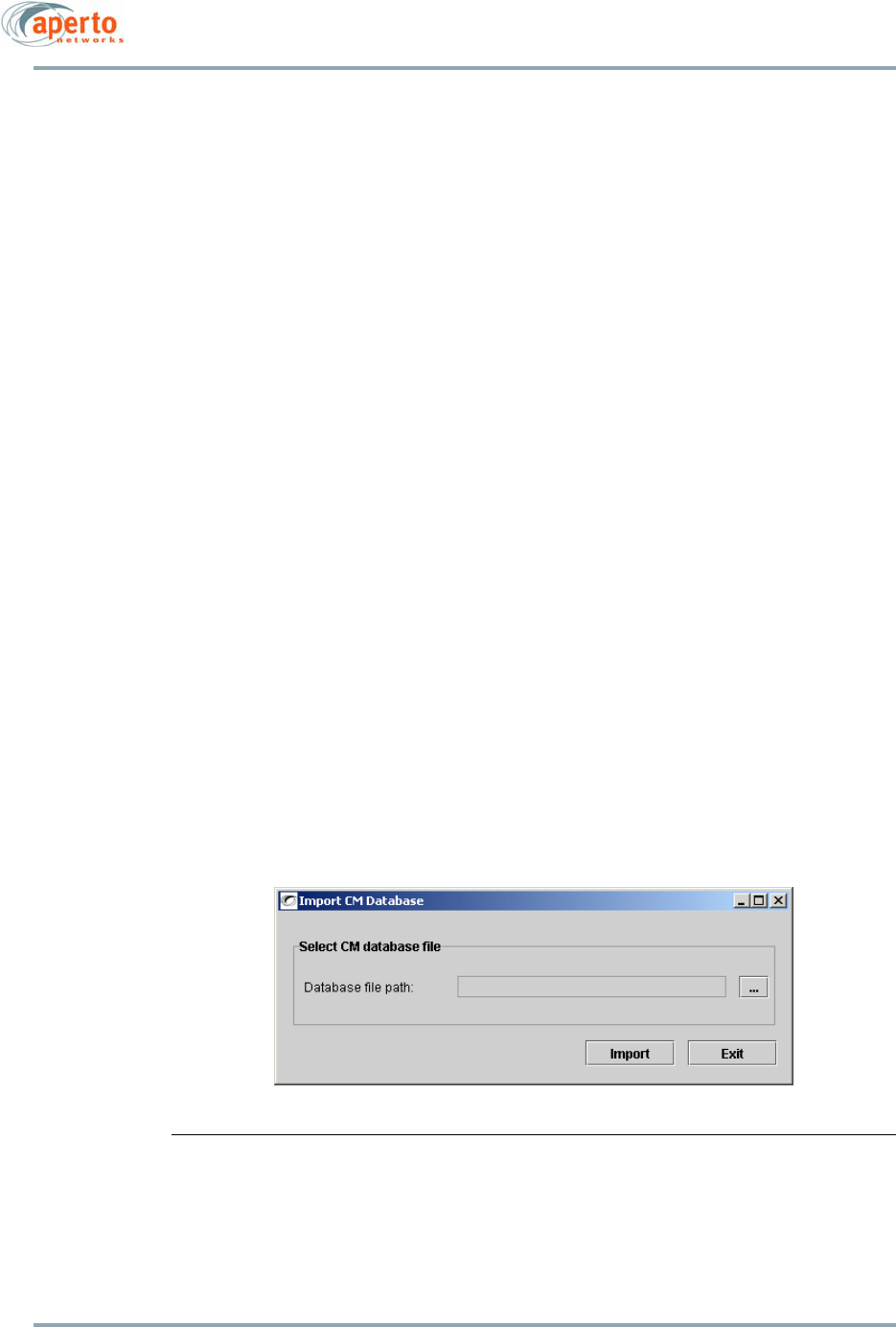
6. Click on the Import CM database button in either the Install Option or Configuration
window.
7. The Import CM Database window shown in Figure 5-4 will appear. Specify the Data-
base file path (the location of the IM.DAT file) and click on Import.
8. Wait for the indication that the file has been downloaded.
.
Figure 5-4 Import CM Database Window
5–7
10004880 Rev. D1
Chapter 5. The PacketWave AIM
Basic Configuration
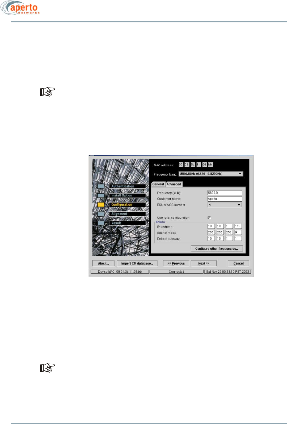
9. In the Install Option window, select Setup; then click on the Next>> button. The
Configuration Window will be displayed, as shown in Figure 5-5. The Configuration
Window shows the configuration retrieved from the PacketWave 200. The MAC
address should be the same as recorded on the label on the unit.
If the IM.DAT file has been downloaded as described under Downloading the BSU’s
IM.DAT File on page 5-6, the only parameters you need to configure are the BSU’s
WSS number and the BSU ID (name); the others will be determined automatically
using the IM.DAT file. Steps 10 to 13 may be skipped.
10. In the Configuration Window, select the frequency band of the wireless link from
the drop-down menu. (This selection must match the frequency band of the
PacketWave 200.)
.
Figure 5-5 Configuration Window: General
11. With the General tab selected in the Configuration Window as shown in Figure 5-5,
configure the following parameters as appropriate:
a. In the Frequency (MHz) field, select the center frequency for the wireless link
from the pull-down menu.
You will need to determine an appropriate center frequency prior to per-
forming this configuration. Aperto has no way of suggesting a default
value appropriate to your area. As soon as you finish configuring the
PacketWave 200, it will begin transmitting on the selected frequency.
b. In the Customer name field, enter a name to identify the PacketWave 200.
Chapter 5. The PacketWave AIM
5–8
10004880 Rev. D1
c. In the BSU’s WSS number field, select the wireless port with which the SU
will communicate.
d. If local IP configuration is chosen, specify the appropriate IP address, Subnet
mask, and Default gateway for the PacketWave 200. Alternatively, uncheck
the Use local configuration box to enable the PacketWave 200 to receive IP
configuration from the BSU using DHCP.
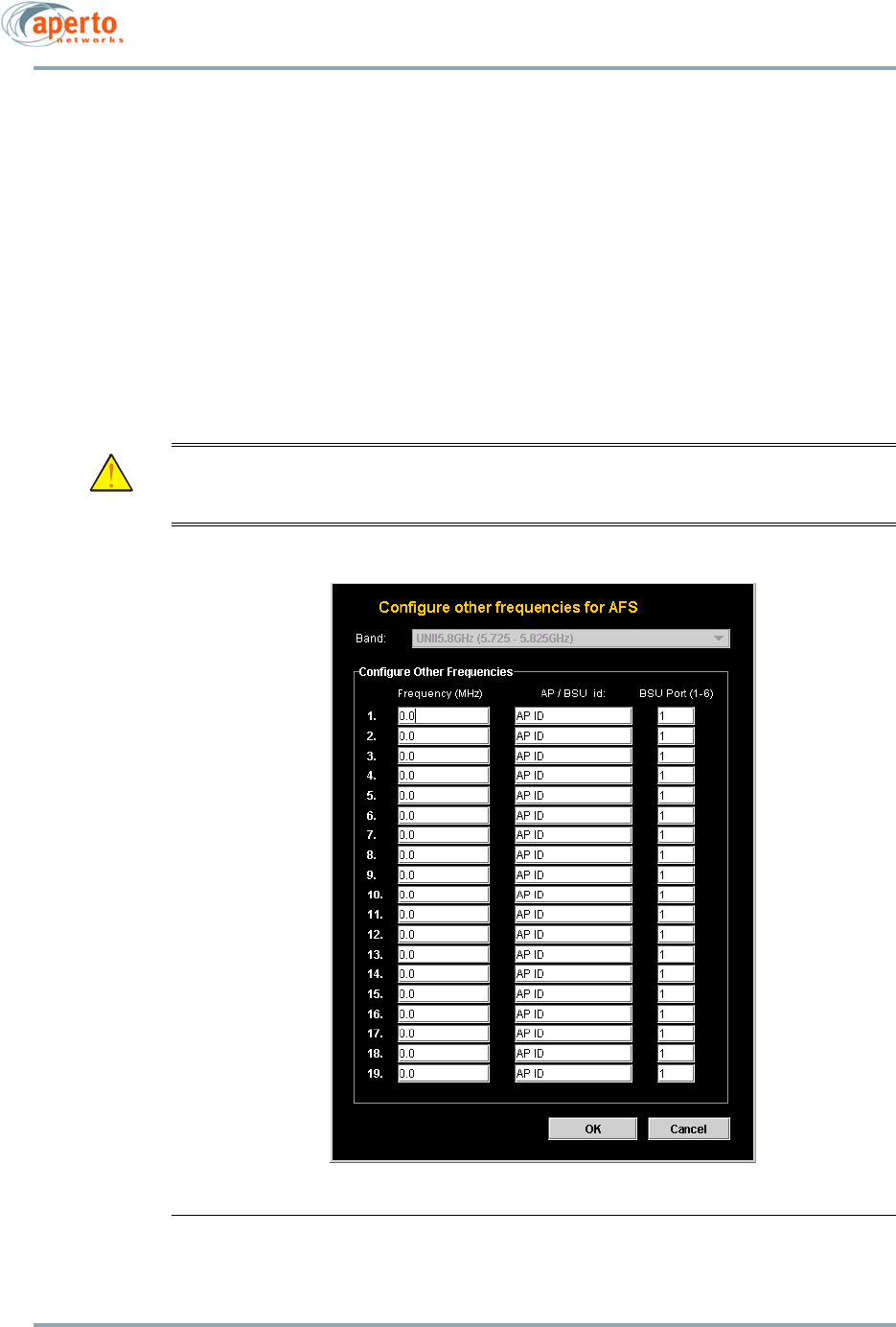
12. If Automatic Frequency Selection (AFS) is desired, you can click on the Configure
other frequencies button to open the AFS Frequencies window shown in Figure 5-6.
AFS will be enabled if you specify at least one alternate frequency. To make antenna
aligning easier, however, Aperto recommends that you specify additional frequen-
cies for the PacketWave 200 via the Web GUI after antenna alignment has been per-
formed. (See Wireless Interface Configuration on page 7-13.)
CAUTION: Enabling AFS during initial setup using the AIM will mean that the
PacketWave 200 will be likely to switch frequencies every 2 minutes dur-
ing antenna alignment, making the procedure very difficult.
Figure 5-6 Configure Other Frequencies Window
5–9
10004880 Rev. D1
Chapter 5. The PacketWave AIM
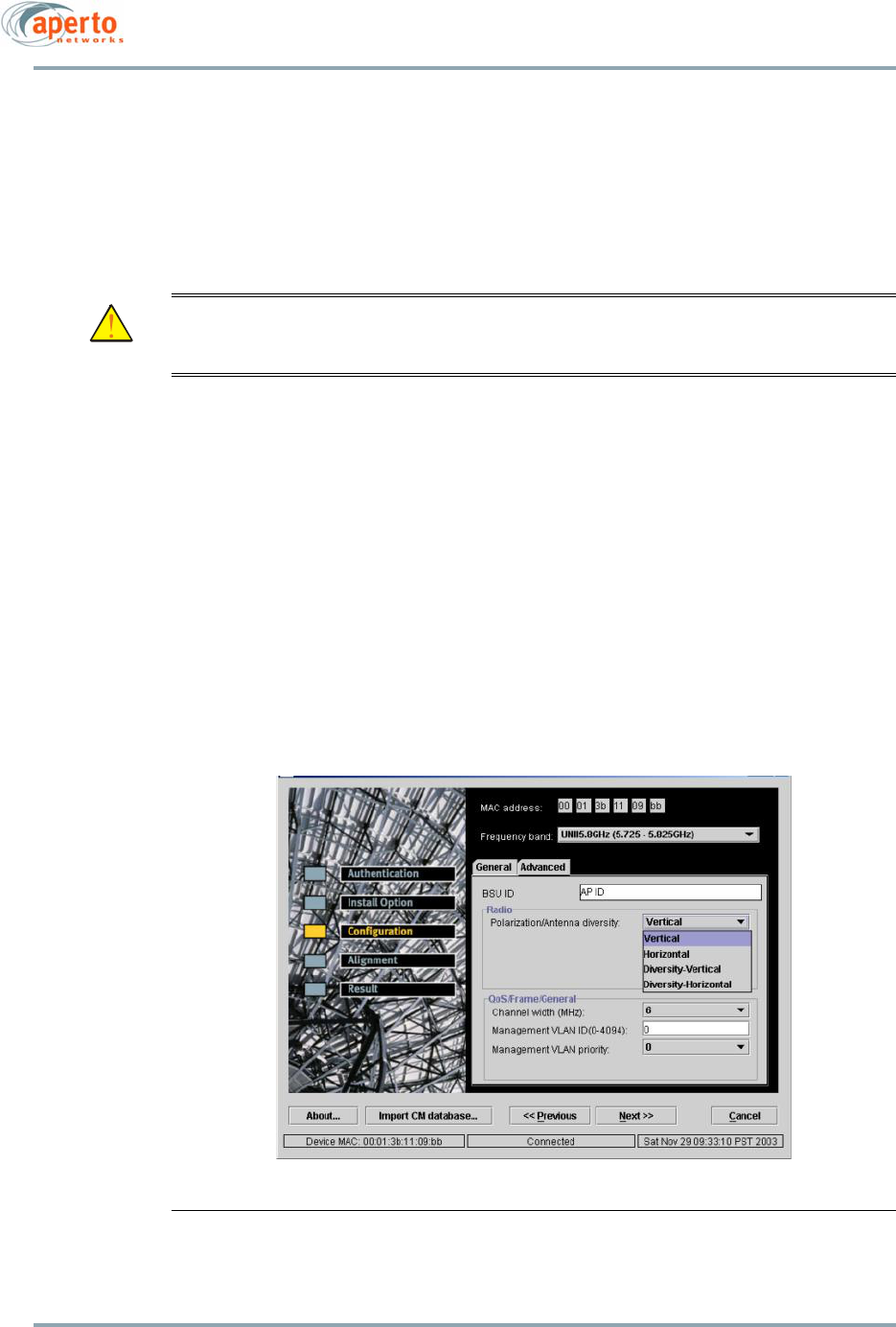
13. In the Configuration Window, click on the Advanced tab to view additional config-
uration options as shown in Figure 5-7. Configure the following parameters as
appropriate:
a. In the BSU ID field, enter the name of the PacketWave 200’s Base Station
Unit, as specified in the configuration of the BSU. Remember that the BSU ID
is case-sensitive.
CAUTION: Since the BSU and SU both use the BSU name and wireless port in the
signal scrambling algorithm, the BSU and SU will not be able to commu-
nicate if the BSU name is not entered correctly.
b. Select the Polarization/Antenna Diversity from the drop-down menu.
NOTE: If you are unsure about what to select, the default (Vertical) will probably
be an appropriate choice.
c. Use the drop-down menu to select the Channel Width. If you are unsure, stick
with the default selection.
d. For VLAN applications, specify the Management VLAN ID and Management
VLAN priority. Usually, the Management VLAN ID should be the same for the
SU and BSU. If you leave the value at the default of 0, the SU will automati-
cally learn and use the BSU’s Management VLAN ID.
NOTE: VLAN configuration is performed primarily using the Configuration Man-
ager. Only the VLAN management ID and priority can be set locally using the AIM.
Figure 5-7 Configuration Window: Advanced
Chapter 5. The PacketWave AIM
5–10
10004880 Rev. D1
14. When you have finished specifying configuration parameters, click on the Next>>
button.
15. If you logged on using the default password, the AIM will prompt for a more secure
password as shown in Figure 5-8.
WARNING: Once the new password has been selected, there will be no default pass-
word for emergency access. Therefore, be careful not to lose the pass-
word.
If you are ready to specify the permanent AIM password, enter the new password.
Otherwise, enter isp to retain the default password. Then click OK.
NOTE: If you retain the default password by entering isp, the Change Password
window will be displayed again the next time the AIM Setup mode is used.
Figure 5-8 Change Password Window
16. After you click Next>> in the Configuration Window (and specify a new password is
necessary), the AIM will send the configuration choices to the PacketWave 200,
then reset the device. The status windows shown in Figure 5-9 will be displayed,
the one on the left first followed by the one on the right.
17. When the restart is finished, the AIM will go into antenna alignment mode, display-
ing the Alignment Window shown in Figure 5-10.
AIM will change the password of a Subscriber Unit (SU) at initial setup. This was done
for security reasons. If this was not true and the AIM software was to fall into the wrong
hands, it might be possible to cause significant problems in the service offering of the
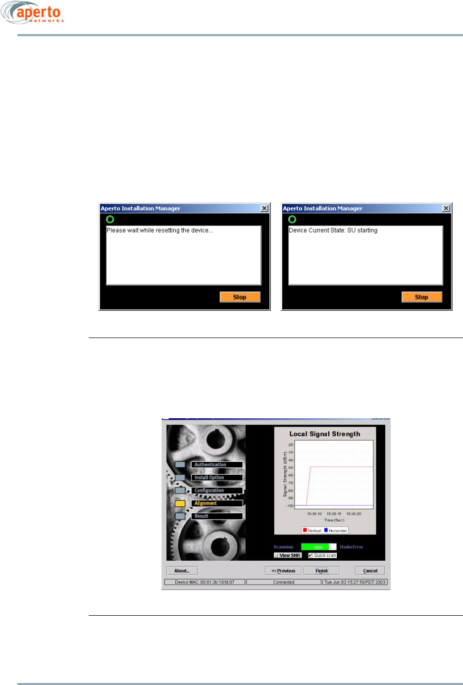
5–11
10004880 Rev. D1
Chapter 5. The PacketWave AIM
SU. For this reason, please be sure to correctly enter the password when AIM requests
that the password be changed.
AIM checks for the default password to determine that a password requires changing.
If you wish to continue using the default password, simply re-enter the default pass-
word when prompted to make a password entry change.
If the password is forgotten or not entered correctly, there is a possibility of using the
WEB interface to correct the problem. Please contact Aperto customer support for
instructions on using the debug password to correct the problem.
Figure 5-9 Restart Status Windows
Figure 5-10 Alignment Window — Local Signal Strength Graph

Chapter 5. The PacketWave AIM
5–12
10004880 Rev. D1
Aligning the Antenna
When the Alignment Window is displayed (Figure 5-10), the ODU will begin slowly beep-
ing. The beep is an audio indication of the strength of the signal received from the base
station. As reception gets stronger (within the range from -50dBm to -100dBm), beeping
increase in pitch and frequency, becoming a continuous tone when the signal is optimal.
To align the antenna, perform the steps in this section.
18. For most situations, verify that Quick scan in the Alignment window is checked as
shown in Figure 5-10. This will cause the PacketWave 200 to scan through frequen-
cies and transmission variables such as gain more quickly than it would otherwise
do. Generally, Quick scan should be unchecked only when there are multiple fre-
quencies (AFS) or the SU will be connected to more than one BSU/WSS for backup.
19. To use the audio signal for antenna alignment:
a. Adjust the position of the ODU for the highest pitch and frequency of the
beeping, ideally finding a position which results in a continuous tone. Secure
the ODU in that position.
b. When the ODU receives a continuously strong signal for one minute (specifi-
cally, when the signal-to-noise ratio is higher than 16 dB and the signal
strength is greater than -88 dBm without varying by more than 2 dB for one
minute), the PacketWave 200 will become operational with an audio tone
similar to a telephone ringing.
20. To use the AIM graphs for antenna alignment:
a. While viewing the graph shown in Figure 5-10, move the antenna to maximize
the signal strength as shown on the graph. Values greater than -82 dBm will
work in 16QAM. Values greater than -89 dBm will work in QPSK.
If the signal does not move up from the bottom of the Local Signal Strength
graph (i.e., shows -100 dBm), do the following:
• Verify that the frequency and BSU ID were correctly configured.
• If the link has line-of-sight between the antennas, you should know the
general direction to align the antenna. Start in that direction. Move the
antenna every few seconds until the Local Signal Strength line rises at
lease once. Once it rises, slow the movement of the antenna. If the Sig-
nal Indicator line has not risen after 2 to 3 minutes, it is best to click the
Previous and then the Next buttons to reset sequence.
• If the installation is not line-of-sight, either search for a first synchroni-
zation (as indicated by the rise of the Signal Indicator line) or just pick
a direction to align the antenna.
b. Once the Local Signal Strength value is maximized, click on the View SNR
button to display the full window as shown in Figure 5-11. SNR (signal-to-
noise ratio) values in the red area are not good; values in the yellow area are
acceptable; values in the green area are best. (However, the unit can operate
reliably to an SNR level of 12 dB in QPSK.)
c. Adjust the antenna again until Local Signal Strength and SNR are maximized.
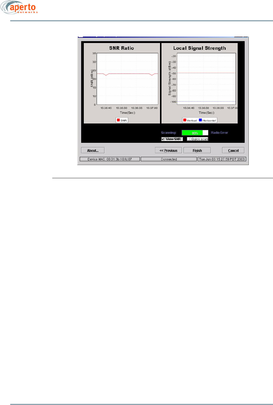
5–13
10004880 Rev. D1
Chapter 5. The PacketWave AIM
Figure 5-11 Alignment Window with SNR Graph
NOTE: Quick scan is a mode for frequency scanning in AIM. In quick scan the
signal alignment is rapidly adjusted for minor differences. Quick scan will not
change frequencies even if there are multiple configured frequencies in the AIM
AFS table. This may cause a problem where the target frequency is not the appro-
priate BSU frequency for the Subscriber Unit (SU) because no signal strength will
be reported. Once the user selects the finish button, the SU will scan all frequen-
cies and become operational. If there are multiple frequencies you would like
AIM to select, de-select the quick scan option on AIM.
21. Click on the Finish button in the Alignment window.
22. A series of pop-up windows will display, showing the progress of the application.
The PacketWave equipment must perform automatic transmission strength and
radio gain adjustment, become operational, and perform IP stability testing before
the application is complete.
a. First, parameters are sent to the PacketWave 200; then the unit is reset and
the antenna alignment flag is set. This takes a few minutes of time, during
which the window shown in Figure 5-12 will be displayed.
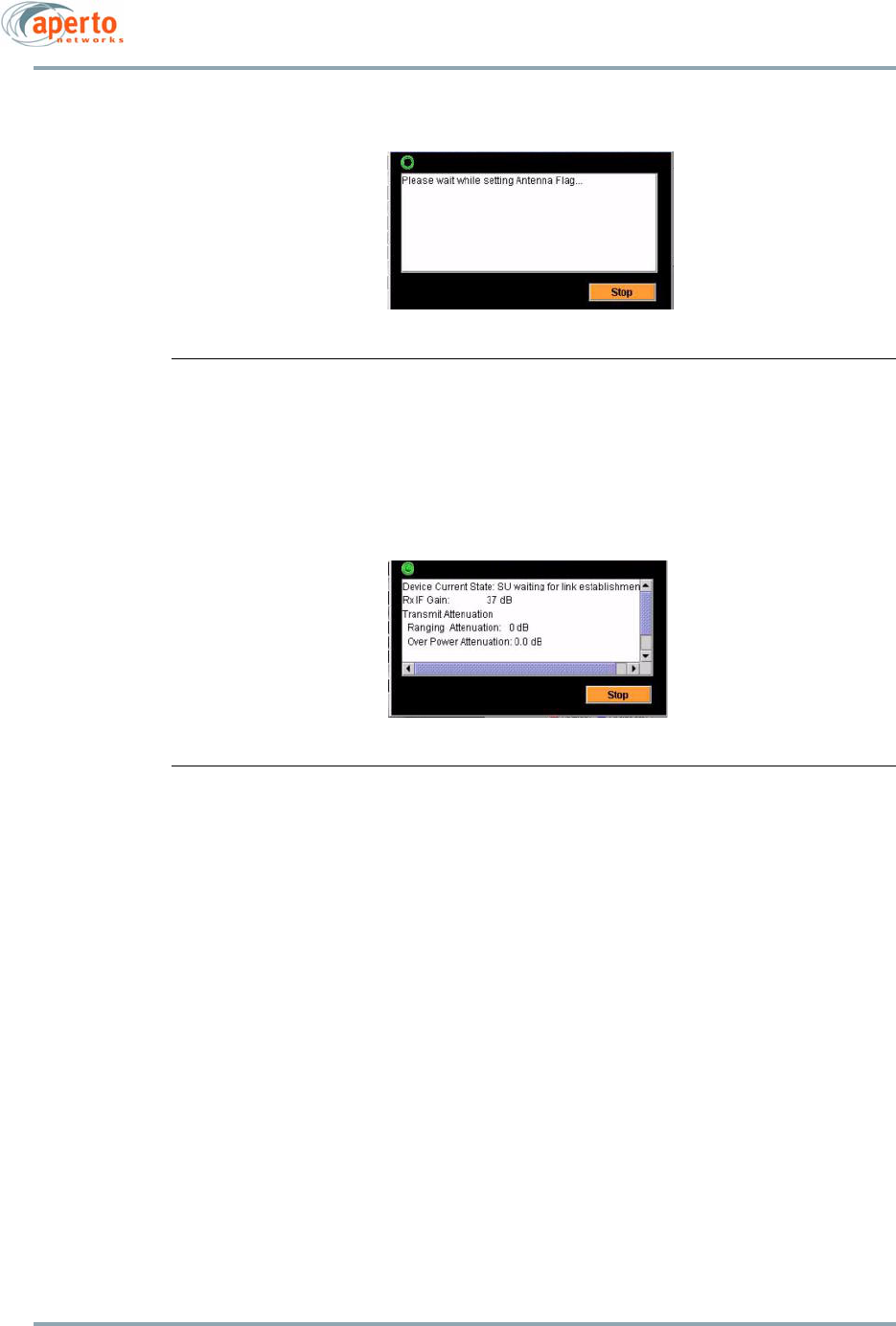
Chapter 5. The PacketWave AIM
5–14
10004880 Rev. D1
Figure 5-12 Setting Antenna Flag Window
b. When the PacketWave 200 has reset, the window shown in Figure 5-13 is dis-
played. This window shows the current state of the unit, the radio gain, and
transmit attenuation, and is refreshed periodically.
Figure 5-13 Device State Window
c. Next, the AIM performs a standard ping test with the BSU, displaying the win-
dow shown in Figure 5-14.
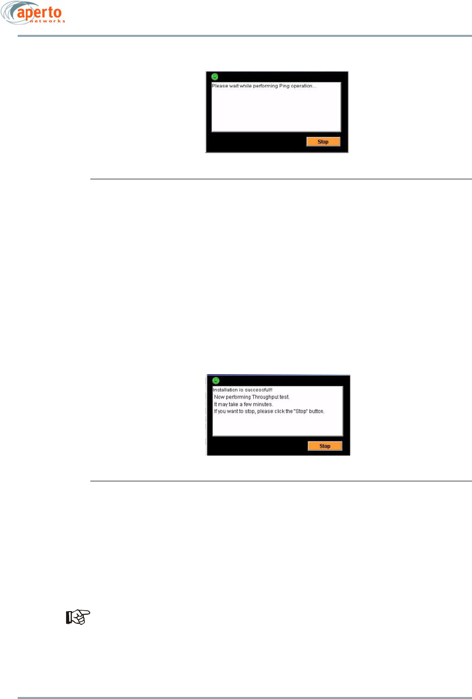
5–15
10004880 Rev. D1
Chapter 5. The PacketWave AIM
Figure 5-14 Performing Ping Test Window
NOTE: At the completion of the AIM cycle, a throughput test is performed. It is
important to note that this value is performed at Best Effort. Therefore the value may
be skewed if other Subscriber Units are currently sending traffic. Also, it is most
likely that when the throughput test is started, the forward error correction and mod-
ulation is at its most robust value. This causes the initial portion of the throughput to
possibly be slower at the beginning of the test, once again skewing the throughput
speed. A more accurate value may be obtained by re-running the throughput test.
d. After the ping test, the AIM performs a throughput test (an FTP transfer of 1
megabyte of data up and down the wireless link), displaying the window
shown in Figure 5-15.
Figure 5-15 Performing Throughput Test Window
e. This test may take a few minutes to complete, depending upon the signal
characteristics. If you are not interested in the throughput test, or if the
throughput test takes more than 10 minutes, click on the Stop button.
f. When the throughput test is finished or stopped, the window shown in
Figure 5-16 is displayed, showing results of the ping and throughput tests.
These results and RF transmission results are recorded in a text file with
the name of the IP address, in the directory in which the AIM application
is loaded (normally C:\aim). Each time the Setup or Test function suc-
cessfully executes, this file is updated.
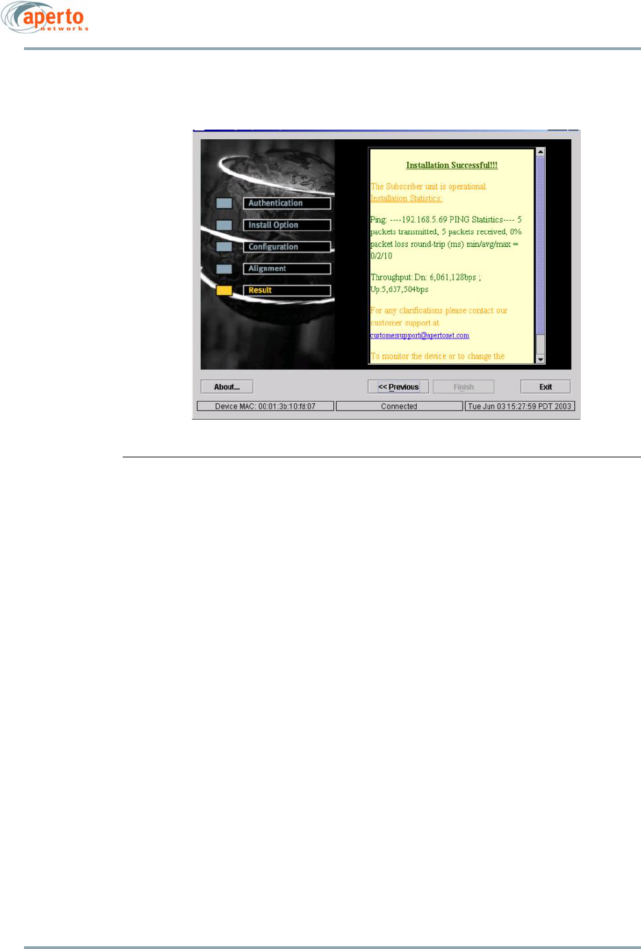
Chapter 5. The PacketWave AIM
5–16
10004880 Rev. D1
.
Figure 5-16 Installation Results Window
23. It is important to check the RF and IP transmission results to see if you have the
best possible wireless connection. If the results are not acceptable, perform the
steps described under Re-aligning the Antenna (Continue with Setup Mode) to
repeat the alignment process:
24. If you are ready to close the AIM, click on the Exit button of the Installation Results
window. The AIM will prompt for confirmation that you really want to exit.
NOTE: Advanced Installation Manager (AIM) performs radio checks following the
antenna alignment. This will allow the installer to check radio cables during align-
ment testing if no signal or a weak signal is being shown on the alignment
screen. This may cause confusion in detecting the difference between a radio not
properly connected and no coverage. Click on the finish button from the antenna
alignment screen, if in any doubt. The radio will be checked and the user will be
informed about the radio connectivity.
Viewing Status of the Wireless Link (Link Status Mode)
To view link status:
1. Go to the Install Option window (Figure 5-3) in one of two ways:
• Perform steps 1 through 5 under Using the Aperto Installation Manager on page
5-4.
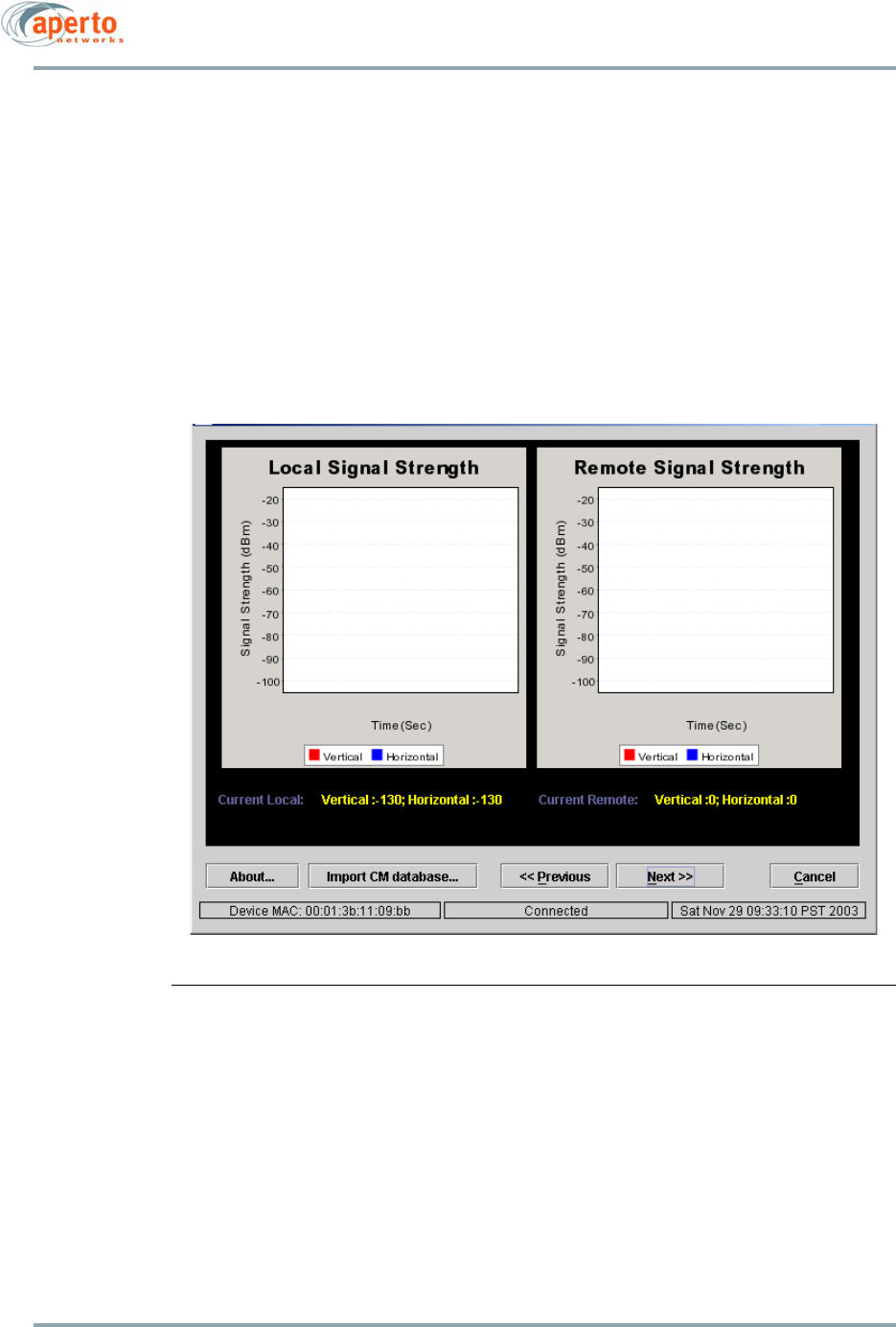
5–17
10004880 Rev. D1
Chapter 5. The PacketWave AIM
• After completing an AIM mode, click on the Previous button until the Install
Option window is displayed.
2. Select Link Status and click on the Next>> button.
3. The Link Status window shown in Figure 5-17 will be displayed, showing local sig-
nal strength (as received by the SU) and remote signal strength (as received and
reported by the BSU) over time.
4. Click on the Next>> button when you are finished viewing the link status. The Install
Options window (Figure 5-3) will be displayed.
Figure 5-17 Link Status Window for PacketWave 200
NOTE: In scanning mode of AIM, the Subscriber Unit also adjusts the synchro-
nization. The synchronization is necessary to match that of the Base Station. It is
normally carried in the wireless frame. Since it is possible that the SU has not yet
found the appropriate signal as it is scanning, it is possible that the synchroni-
zation adjustment may be misaligned. To ensure proper antenna alignment, do
not spend more than 10 minutes in the alignment phase of AIM. Use the previous
and next buttons to restart the process at least every 10 minutes.
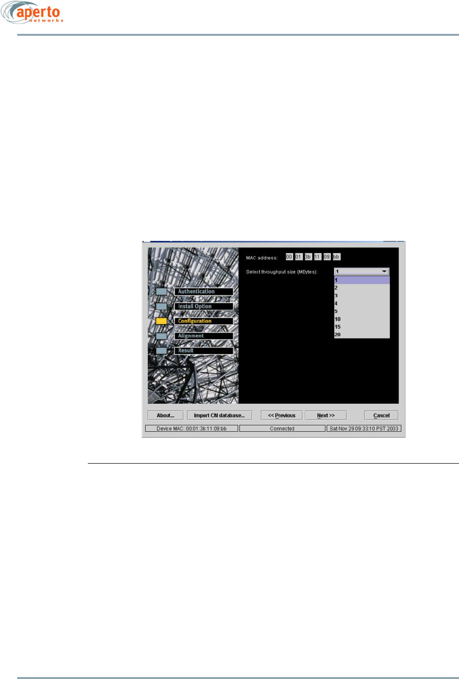
Chapter 5. The PacketWave AIM
5–18
10004880 Rev. D1
Running a Non-Destructive Test (Test Mode)
You can run a non-destructive test of the wireless link at any time. To run a test:
1. Go to the Install Option window (Figure 5-3) in one of two ways:
• Perform steps 1 through 5 under Using the Aperto Installation Manager on page
5-4.
• After completing an AIM mode, click on the Previous button until the Install
Option window is displayed.
2. Select Test only and click on the Next>> key.
3. The Test Configuration window shown in Figure 5-18 will be displayed. Choose the
number of megabytes to be transferred; then click on the Next>> button.
Figure 5-18 Test Configuration Window
4. The Test Results window shown in Figure 5-19 will be displayed, and the test results
text file will be updated.
NOTE: This window is the same as the Installation Results window shown in
Figure 5-16 on page -16.
5. If you are ready to close the AIM, click on the Exit button of the Installation Results
window. The AIM will prompt for confirmation that you really want to exit.
Otherwise, use the <<Previous buttons to return to the window you choose.
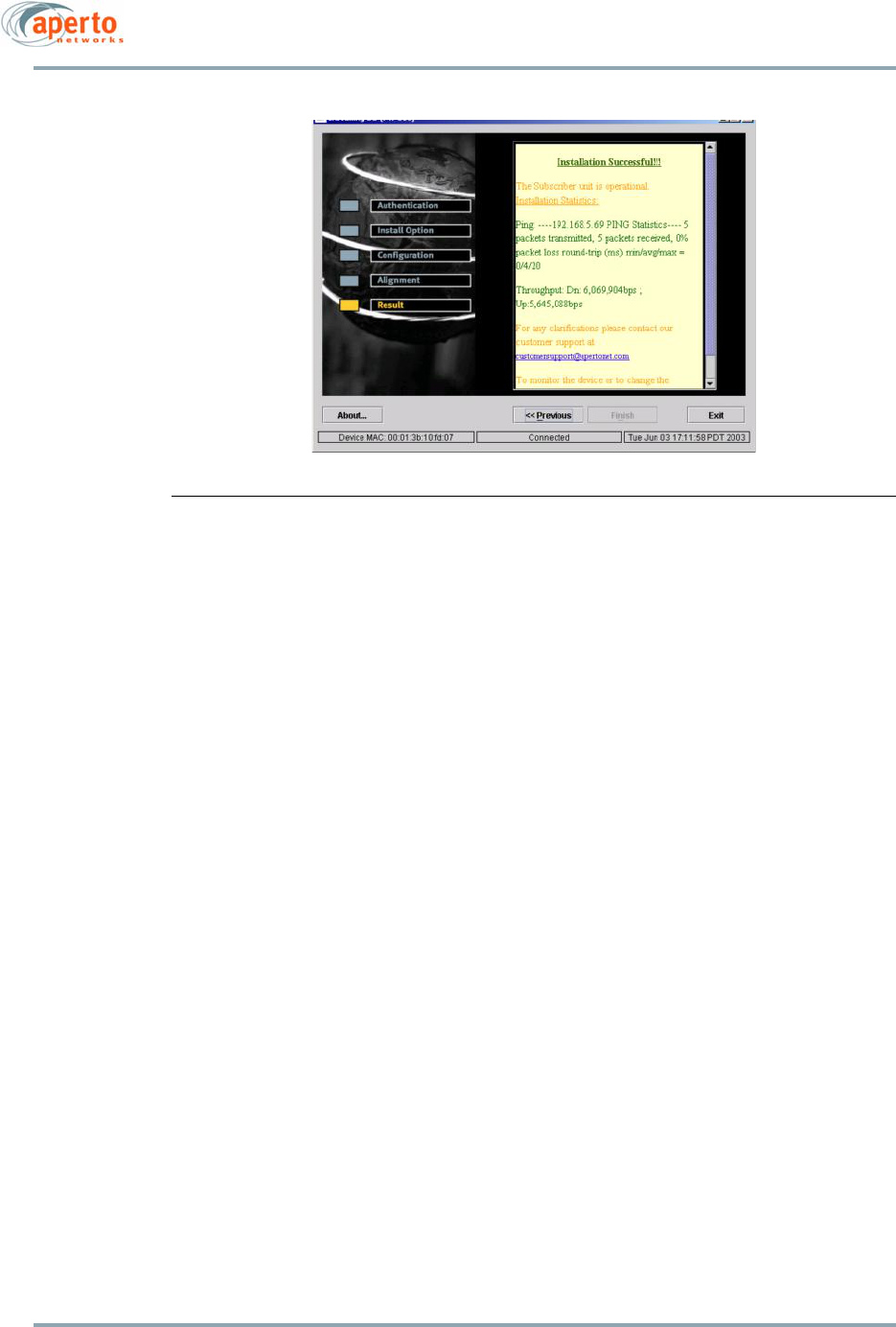
5–19
10004880 Rev. D1
Chapter 5. The PacketWave AIM
.
Figure 5-19 Test Results Window
Pre-provisioning a PW200 for Later Installation (Provision Mode)
The Provision mode is typically used to provision a PacketWave 200 in the lab prior to
installation. This enables the audio auto-alignment feature, described in Chapter 4.
NOTE: The Provision mode can also be used to re-enable the audio auto-align-
ment feature, should that be desired. After Provision mode, the PacketWave 200
is configured to go directly into audio alignment mode at power-up. If the audio
auto-alignment feature has not been enabled by using the AIM Provision mode,
alignment can be performed only using the AIM.
To use the Provision mode:
1. Go to the Install Option window (Figure 5-3) in one of two ways:
• Perform steps 1 through 5 under Using the Aperto Installation Manager on page
5-4.
• After completing an AIM mode, click on the Previous button until the Install
Option window is displayed.
2. Select Provision and click on the Next>> key. The Configuration Window will be dis-
played, as shown in Figure 5-5.
3. Configure the PacketWave 200 as described in steps 8 through 14 under Basic Con-
figuration on page 5-7.
4. After configuration has been completed, the AIM will reset the PacketWave 200,
enable audio auto-alignment, and display the Provisioning Results window similar
to that shown in Figure 5-19.

Chapter 5. The PacketWave AIM
5–20
10004880 Rev. D1
Aperto Installation Manager Troubleshooting
This section offers solutions for problems related to the use of the Aperto Installation
Manager (AIM) utility.
Problems Connecting to the Subscriber Unit
If the Aperto Installation Manager fails to connect with the PacketWave 200 after MAC
address/frequency configuration, a “Host unreachable” message will result. Possible
causes and solutions include the following:
• Cabling problem — Verify that a crossover cable is being used, and that it is
securely connected at both ends.
• No power to the PacketWave 200 — Make sure that the Interface Box is properly
connected to an AC outlet and to the Outdoor Unit (ODU), and that the Interface
Box ODU Port’ LEDs indicate that power is on.
• Incorrect MAC address — Check the MAC address entered against the MAC address
on the PacketWave 200 ODU, and correct if necessary.
• Computer does not have fixed IP addresses — On the computer running the AIM,
ensure that the Ethernet connection is configured with a fixed IP address, subnet
mask, and gateway.
• Multiple Ethernet connections enabled — On the computer running the AIM, verify
that only the Ethernet connection to the PacketWave 200 is enabled. If multiple
Ethernet connections are enabled, the AIM will not be able to determine the correct
connection to use.
• Another application using the port — Close any application that might be using the
computer port employed by the AIM. Use the Windows task manager or LINUX/UNIX
process status as appropriate, and remove the task or reboot the computer as nec-
essary. (Sometimes Windows will have an extra Java task that is using the port.)
Problems Communicating with the Base Station Unit
After antenna alignment is finished, the Aperto Installation Manager (AIM) establishes
communication with the Base Station Unit, downloads configuration and IP information,
and performs ping and throughput tests with the Base Station Unit. The SU state during
establishment of the communication link and initialization of the SU is indicated by mes-
sages in a pop-up window. If the Aperto Installation Manager hangs at a particular state,
that state will help identify the nature of the problem.
If establishment of the communication link and initialization of the SU succeed, but the
ping and throughput tests are not successfully completed, the Aperto Installation Manager
indicates installation failure in the Results Window.
Possible causes and solutions for a failure in communication with the Base Station Unit
include the following:

5–21
10004880 Rev. D1
Chapter 5. The PacketWave AIM
• Incorrect frequency entered — Verify that the frequency information specified for
the SU matches the BSU. (Typically, the AIM will have hung at the “searching for
sync” or “link establishment” state.)
• Incorrect BSU ID entered — Verify the BSU ID, which is case-sensitive and must
match the ID as entered on the BSU.
• Incorrect WSS port number entered — Verify that the SU is in the correct sector and
that the correct port number is being used.
• Cable problems — Ensure that the Cat 5 cable between the Interface Box and the
Outdoor Unit is properly and securely connected; that the cable meets the require-
ments given in this manual; and that the cable does not exceed 100 m (330 ft) in
length if Cat 5E, or 50 m (165 ft) if Cat 5. (Typically, the AIM will have hung at the
“searching for sync” or “link establishment” state.)
• Incorrect antenna alignment — Try re-running the AIM and aligning the antenna
again, making sure to secure the Outdoor Unit in the position where the strongest
signal is being received. (Typically, the AIM will have hung at the “searching for
sync” or “link establishment” state.)
• BSU wireless failure — Confirm that the BSU’s wireless interface to the SU is oper-
ating correctly. (Typically, the AIM will have hung at the “searching for sync” or “link
establishment” state.)
• DHCP failure — If the Installation Manager hangs in the “DHCP request sent” state,
the communication link has been successfully established but there has been a
problem with DHCP or configuration downloading. Ensure that:
-The DHCP server has a proper entry for the SU’s MAC address.
-The DHCP server has an established route to the SU.
-The TFTP server has a valid configuration file for the SU.
• Noisy or bad communication link — If the throughput test is inordinately slow, the
communication link’s error rate may make it inappropriate to put the SU into ser-
vice. Experience has shown that the test can take up to ten minutes and still be
completed without errors. If the throughput rate is not appropriate, try aligning the
antenna in its current location or relocating the antenna. If this does not solve the
problem, perhaps the sensitivity of the antenna at the base station should be
adjusted (depending on performance of other SUs in the sector).
• Signal too strong — If the base station antenna is adjusted for communication with
distant SUs, an SU near the base station may not be able to turn its transmit power
low enough to avoid overdriving its signal to the base station. (Typically, the AIM
will have hung at the “searching for sync” or “link establishment” state.) If this
occurs, align the subscriber antenna for the maximum signal; then adjust the
antenna alignment upward (“detuning” the antenna to decrease transmit power),
keeping the signal strength below -40 dBm.
NOTE: Please be sure to have the correct frequency, BSU ID, sector number, and
channel width when running AIM. Without these correct entries, the unit will not be
able to synchronize with the Base Station and you will not be able to align the
antenna. The lack of signal will appear the same as a non-covered area. Either use a

Chapter 5. The PacketWave AIM
5–22
10004880 Rev. D1
“Have Disk” file generated by the Configuration Manager or use the correct WSS
number.

6–1
10004880 Rev. D1
6
The Web GUI
The PacketWave 200 Series Subscriber Unit includes a Java-based graphical user interface
(GUI) which runs on a standard Web browser (Netscape 4.74 or Internet Explorer 5.0). Func-
tions which can be performed using the Web GUI include:
• Viewing network connectivity.
• Monitoring status and performance.
• Reviewing configuration.
• Making basic configuration changes.
• Uploading configuration changes to the Subscriber Unit’s configuration file on the
TFTP server.
• Resetting the PacketWave 200.
ISP and Subscriber Logon Levels
The Packet SU Web GUI features different logon levels for ISPs and subscribers, each pro-
tected by a different user-set password. (There is also a Debug logon level, reserved for
Aperto use.) The ISP logon level provides access to all areas of SU configuration, status
reporting, performance monitoring, and operating commands. The Subscriber logon level
is limited to:
• The site connectivity view of the SU home page.
• Password Configuration page (subscriber password only).
• Configuration pages for DHCP, NAT, and routing functions
• Read-only PPPoE/PPP Configuration page.
• Configuration Upload utility.
• System Status and PPPoE/PPP Status pages.
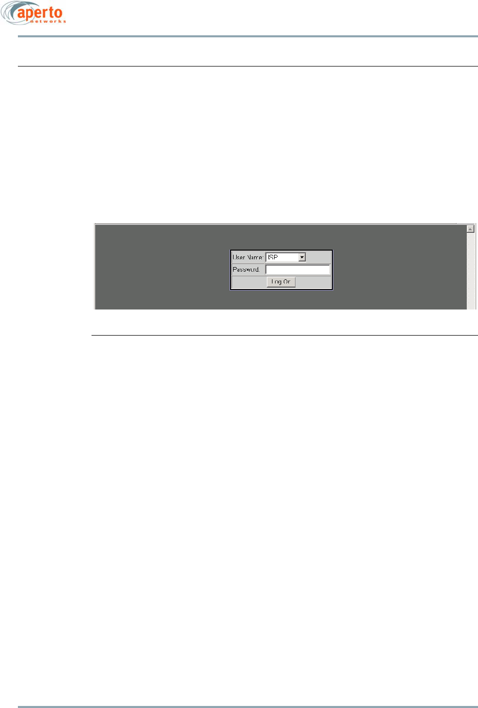
Chapter 6. The Web GUI
6–2
10004880 Rev. D1
Accessing the Web Interface
To access the Web GUI:
1. On a computer with IP access to the PacketWave 200 (via either the LAN or wireless
interface), open Netscape 4.74 or Internet Explorer 5.0.
NOTE: Other browsers could show some anomalies.
Enter the URL, http://<
PW200
IP address>/. The logon page will appear, as shown in
Figure 6-1.
Figure 6-1 SU Web GUI Logon Screen
2. Select the ISP or Subscriber user name.
3. Enter the correct password. (The password is case-sensitive.)
NOTE: The default passwords are isp and subscriber. For security, different
passwords should be defined. (Passwords can be specified via the Web GUI,
SNMP, and the Configuration Manager.)
4. Click on the Logon button.
5. If the browser prompts that it needs to load a plug-in, allow it to do so.
6. Wait for the Web interface home page to open, as shown in Figure 6-2.
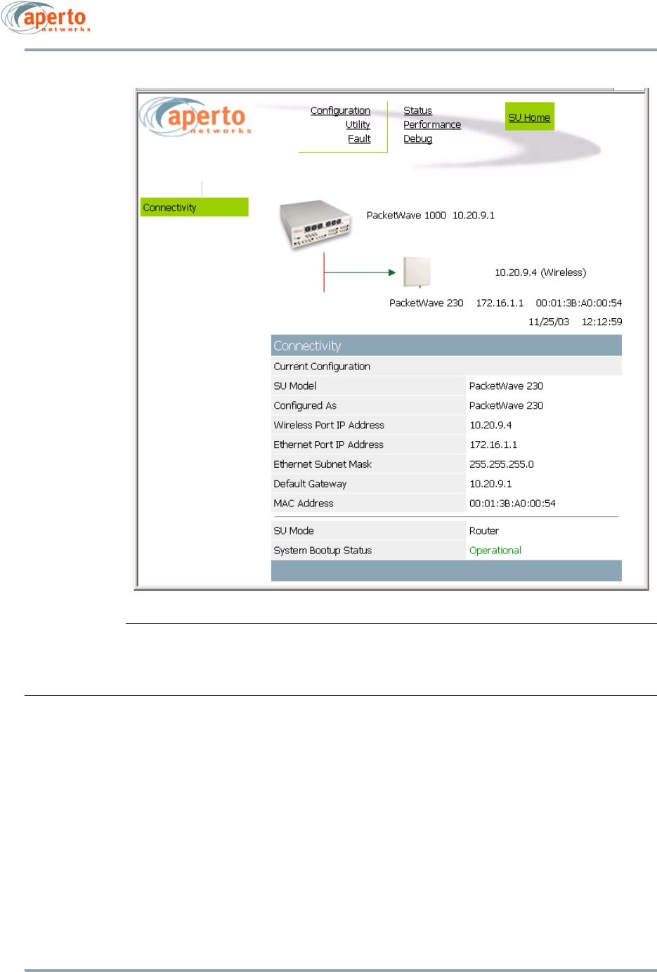
6–3
10004880 Rev. D1
Chapter 6. The Web GUI
Figure 6-2 Web GUI Home Page
Features of the Web Interface
The Web interface pages share the basic elements identified in Figure 6-3.
Home Page: Connectivity View
As shown in Figure 6-2, the home page provides a graphical representation of base sta-
tion-to-subscriber connectivity. The arrow pointing to the PacketWave 200 icon indicates
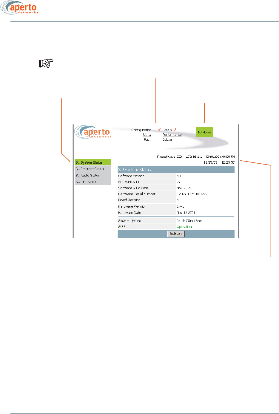
Chapter 6. The Web GUI
6–4
10004880 Rev. D1
wireless channel status: green if good or red if down. Operating mode, IP network, and
MAC address information are presented in a table below the graphical representation.
Status indications on the connectivity view are updated dynamically every 30
seconds.
Figure 6-3 Basic Elements of Web GUI
Main Menu and Submenu
The Main Menu lists the various categories of functions available via the Web GUI. The ISP
logon level provides the five Main Menu categories shown in Figure 6-3. For the Subscriber
logon level, the Main Menu lists Configuration and Status categories only. To select an
item from the Main Menu, click on it. Orange crescents will bracket the menu item to show
that it has been selected (see the Configuration item in Figure 6-3).
The Submenu is context-sensitive, changing as different Main Menu items are selected.
The Submenu lists the pages available under the selected Main Menu category. Click on
the appropriately-labeled box in the Submenu to display the desired page. Figure 6-3
shows the page displayed when the System option is selected in the Submenu.
Main Menu
Display Header
(may include model, IP address, MAC address, date and time)
Return-to-Home-Page
Button
Submenu

6–5
10004880 Rev. D1
Chapter 6. The Web GUI
Submitting and Uploading Changes
Pages on which configuration changes can be entered include a Submit button at the bot-
tom. Any change entered on the page does not take effect until the Submit button is
clicked.
Clicking Submit affects only the operating configuration of the SU. The SU’s configuration
file located on the BSU’s TFTP server is not altered; therefore, the configuration change
will be lost if the SU is reset or re-powered (after which the SU reverts to the configuration
specified in its configuration file).
To update the SU’s configuration file on the TFTP server with changes made via the Web
GUI, use the Upload Configuration button on the Device Control Utility page (page 6-30).
Clicking the Upload Configuration button will cause all configuration changes currently in
effect to be written into the SU’s configuration file on the TFTP server.
Cancel and Refresh Buttons
Some pages include Cancel and/or Refresh buttons at the bottom.
• Clicking on the Cancel button cancels any changes made on the page; altered fields
will return to their original contents.
• Clicking on the Refresh button refreshes all fields with configuration parameters
downloaded from the TFTP server.
Hyperlinks
Some Web GUI pages include hyperlinks to related pages. For example, the Routing Table
page includes hyperlinks to pages for adding and deleting routes. Hyperlinks are indi-
cated in the method defined in your browser configuration.
In some cases, hyperlinks are implemented using buttons similar to the Submit button.
For example, the Routes Configuration page includes buttons which serve as hyperlinks
to pages for adding and deleting routes.
Overview of SU Web GUI Functions
Table 6-A summarizes the functions available for each of the Main Menu and Submenu
selections.

Chapter 6. The Web GUI
6–6
10004880 Rev. D1
Table 6-A Summary of the SU Web GUI
Main Menu Submenu Functions
Configuration System Show general SU information and status; set customer name
and network access.
Administration Set contact, location, and cell name.
Password * Set password(s) for ISP and/or Subscriber access levels.
Ethernet Show/set configuration of subscriber Ethernet link.
SNMP Configure SNMP management of SU.
VLAN Show VLAN configuration. Read-only.
Wireless Show/set radio and antenna configuration.
Up/Downstream
Default Best Effort
Show configuration of upstream or downstream default best
effort service flow (ID=0). Read-only.
Routes * Allows SU routing table to be viewed and built.
NAT * Allows configuration of SU’s internal NAT routing.
DHCP * Allows configuration of SU’s internal DHCP server.
IP Filter List of all defined IP filters for wireless or Ethernet port.
Hyperlinks to contents of individual filters. Read-only.
PPPoE/PPP * Show/set PPPoE/PPP parameters.
Utility Device Control * Reset SU (ISP only); Upload Configuration.
Fault Event logs List of logged SU events.
E-mail Configure e-mail alert reporting.
Status SU System Status * SU software and hardware info, operational status.
Ethernet Status Subscriber Ethernet link status.
Radio Status SU radio information and status.
SU Link Status Transmit and receive details for wireless link.
PPPoE/PPP Status * Show/set PPP user name and password.
Performance SU System Statistics Basic Transmit and Receive counts. Read-only.
PPPoE Statistics Shoe PPPoE packet counts.
RF Signal Quality Wireless link performance counters. Read-only.
SU Filter Statistics Passed and blocked packets for wireless or Ethernet port.
SU Flow Statistics List of service flows supported by the SU; hyperlink to ser-
vice flow details.
Debug CPE Access to performance displays and debug commands.
* Available at Subscriber level.

6–7
10004880 Rev. D1
Chapter 6. The Web GUI
Configuration Pages
The Web GUI displays SU configuration in numerous individual pages, as indicated by the
Configuration Submenu. In addition, many configuration parameters can be changed via
the Configuration pages.
System Configuration
As shown in Figure 6-4, the system configuration page provides an overview of the
Subscriber Unit’s network and operating parameters. All parameters are read-only except:
•Network Access enables or disables connection to the wireless network.
•Customer Name is a text field identifying the subscriber.
Click on the Submit button to activate any changes made to these two parameters.
A change to the Customer Name field will take effect immediately, without a reboot.
An event will be logged indicating the change (see Figure 6-29). The customer name
will also be changed on the BSU’s SU Inventory page when it is changed at the SU.
This page is available only at the ISP logon level.
Administration Configuration
The Administration Configuration page, shown in Figure 6-5, allows SNMP name, contact,
and location information to be entered for the subscriber site. Any text entry is acceptable,
subject to length limitations for each field.
Click on the Submit button to activate any changes made on this page.
This page is available only at the ISP logon level.
Password Configuration
Passwords for the ISP and Subscriber logon levels are specified on the Password Config-
uration page, shown in Figure 6-6. Passwords which can be defined depend on the current
logon level; if logon is at the Subscriber level, only the Subscriber password fields will be
displayed. The passwords are used for the Web GUI, SNMP, CLI, and FTP.
The password must be entered exactly the same (including case) in the two password
fields to be accepted. After specifying the desired password, click Submit. The Web GUI
will prompt that password storage is temporary, and that the Upload Configuration func-
tion (page 6-30) is required for making the password permanent.
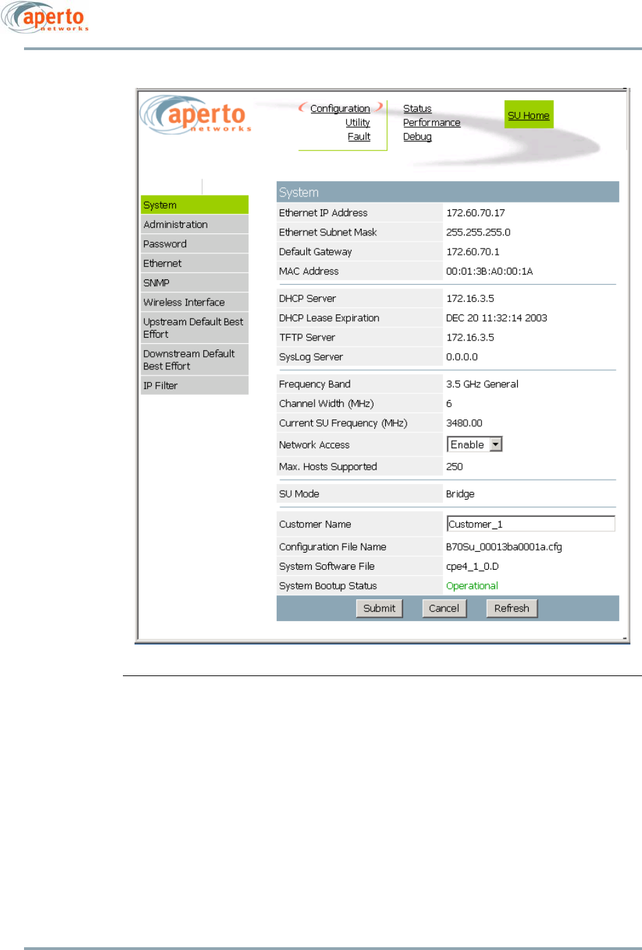
Chapter 6. The Web GUI
6–8
10004880 Rev. D1
Figure 6-4 System Configuration Page
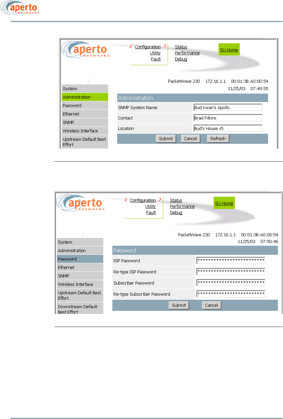
6–9
10004880 Rev. D1
Chapter 6. The Web GUI
Figure 6-5 Administration Configuration Page
Figure 6-6 Password Configuration Page
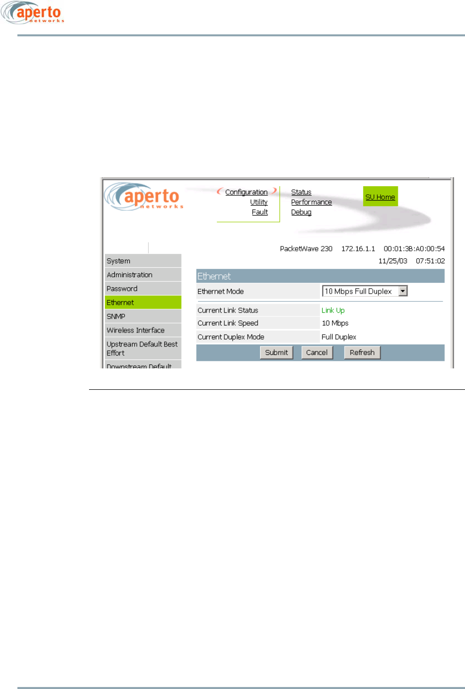
Chapter 6. The Web GUI
6–10
10004880 Rev. D1
Ethernet Configuration
The Ethernet Configuration page, shown in Figure 6-7, allows the Ethernet link to the sub-
scriber’s computer or network to be specified as full or half duplex, 10 or 100 Mbps, as
well as auto-detecting. The page also shows current status of the Ethernet link.
Click on the Submit button to activate any changes made on this page.
This page is available only at the ISP logon level.
Figure 6-7 Ethernet Configuration Page
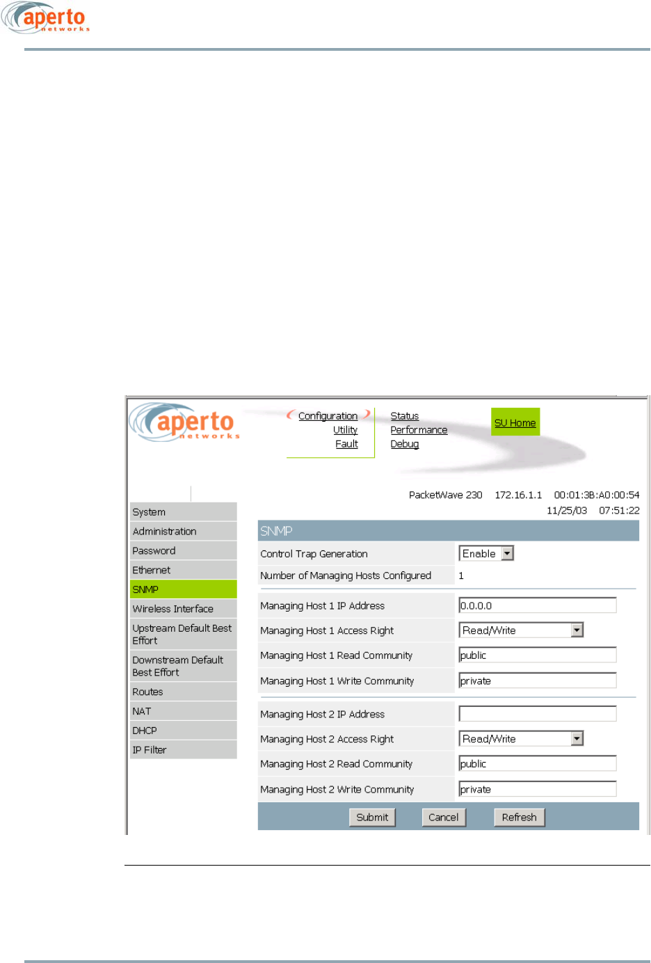
6–11
10004880 Rev. D1
Chapter 6. The Web GUI
SNMP Configuration
As shown in Figure 6-8, the SNMP configuration page allows the viewing and altering of
SNMP parameters for one or two SNMP managers:
• Whether traps will be generated.
• What SNMP manager(s) will be recognized, what access rights they will have, and
the read and write community names.
Click on the Submit button to activate any changes made on this page.
NOTE: This page does not support deletion of SNMP managers.
This page is available only at the ISP logon level.
Figure 6-8 SNMP Configuration Page
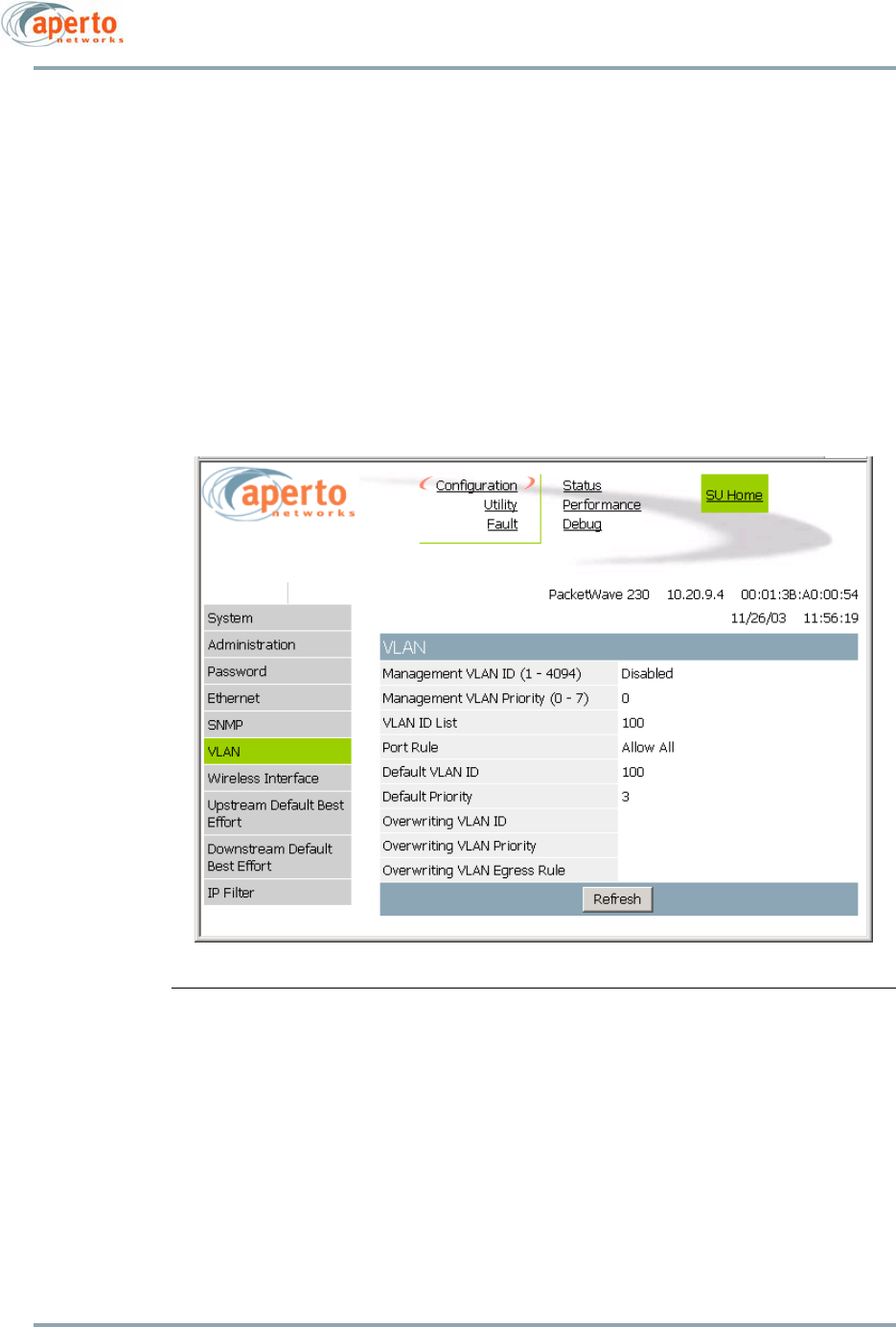
Chapter 6. The Web GUI
6–12
10004880 Rev. D1
VLAN Configuration
The VLAN Configuration option is available only when the PacketWave 200 is configured
for VLAN operation via the Configuration Manager (or CLI). As shown in Figure 6-9, the
VLAN Configuration page shows read-only configuration for VLAN operation.
For an explanation of these VLAN parameters, see the PacketWave 1000 Base Station Unit
Manual.
This page is available only at the ISP logon level.
Figure 6-9 VLAN Configuration Page
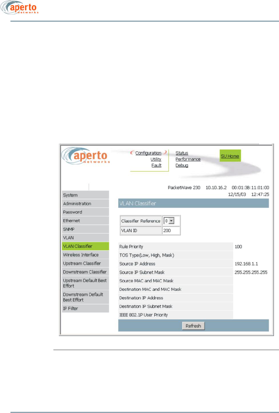
6–13
10004880 Rev. D1
Chapter 6. The Web GUI
VLAN Classifier Configuration
The VLAN Classifier Configuration option is available only when the PacketWave 200 is
configured for VLAN operation and VLAN classifiers are enabled via the Configuration Man-
ager (or CLI). As shown in Figure 6-10, the VLAN Classifier Configuration page shows read-
only configuration for VLAN operation.
Use the Classifier Reference drop-down menu to select the VLAN classifier for which you
want to display configuration.
For an explanation of VLAN classifiers and the parameters on this page, see the
PacketWave 1000 Base Station Unit Manual.
This page is available only at the ISP logon level.
Figure 6-10 VLAN Classifier Configuration Page
Chapter 6. The Web GUI
6–14
10004880 Rev. D1
Wireless Interface Configuration
As shown in Figure 6-11, the Wireless Interface Configuration allows an operator to view
and in some cases change a variety of wireless link parameters:
•Frequency Band — Unit’s frequency band; read-only.
•Channel Width — Unit’s channel width; read-only.
•SU Frequency — The frequency currently being used by the SU; read-only.
•Target BSU ID — The identifier for the SU’s BSU (case-sensitive).
•Target Port ID — The number of the SU’s BSU wireless port.
•Polarization — Antenna polarization: Vertical, Horizontal, Vertical with diversity, or
Horizontal with diversity.
•Frequency Table — Multiple frequencies for the Automatic Frequency Selection
(AFS) feature. To enable up to 19 different alternate frequencies (which may link to
the same or different BSUs and/or wireless ports), enter the desired BSU and Port
IDs and frequencies in the appropriate fields. (The specified frequencies must also
be in the AFS tables for the BSU wireless ports.) AFS will be enabled whenever at
least one frequency is defined in the table.
NOTE: In most cases, no more than 4 or 5 frequencies will be needed. A fre-
quency can be specified more than once to increase its likelihood of being
selected. For optimum performance, AFS frequencies tables for the BSU and SUs
should include the same frequencies in the same order unless the SU includes
frequencies from multiple BSUs and/or wireless ports.
CAUTION: Configurable parameters on this page can significantly affect the perfor-
mance of the wireless link. Do not change any of these parameters
unless you have a solid understanding of their purpose and why they
should be changed.
Click on the Submit button to activate any changes made on this page.
This page is available only at the ISP logon level.
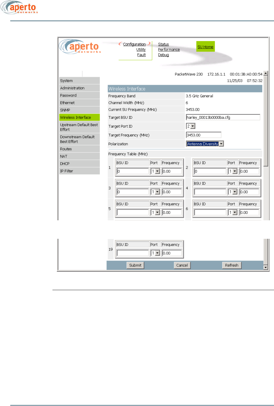
6–15
10004880 Rev. D1
Chapter 6. The Web GUI
Figure 6-11 Wireless Interface Configuration Page
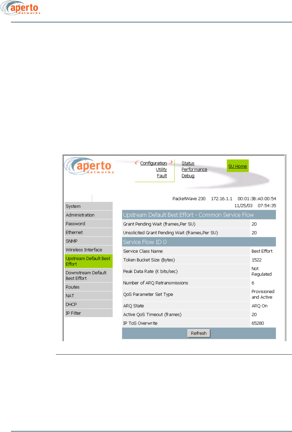
Chapter 6. The Web GUI
6–16
10004880 Rev. D1
Default Best Effort Configuration
All Subscriber Units have at least one service flow in each direction: a Best Effort service
flow with an ID of 0. Any traffic which does not meet a defined classifier (if there are any)
will be assigned to these service flows. Performance parameters of the default upstream
and downstream service flows are configurable using the WaveCenter Configuration Man-
ager, but the Service Flow ID (0) and class (Best Effort) cannot be altered.
Configuration pages for default Best Effort service flows are shown in Figure 6-12 and
Figure 6-13. All fields are read-only.
NOTE: If all traffic will be transmitted using the default Best Effort service flows,
no classifiers need to be defined.
These pages are available only at the ISP logon level.
Figure 6-12 Upstream Default Best Effort Configuration Page
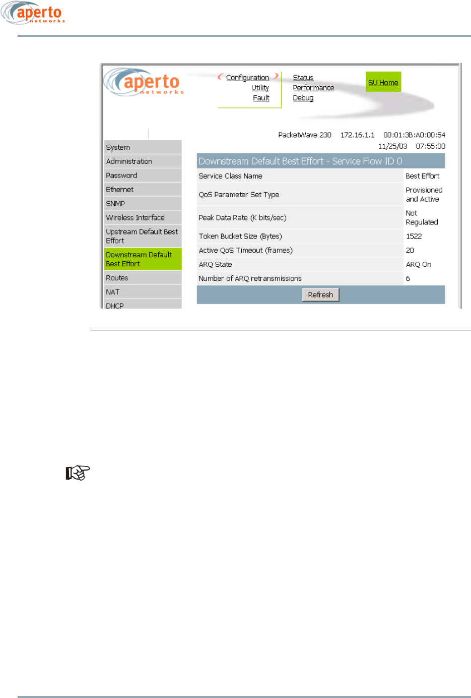
6–17
10004880 Rev. D1
Chapter 6. The Web GUI
Figure 6-13 Downstream Default Best Effort Configuration Page
Routes Configuration
If the Subscriber Unit supports routing, the Routes Configuration pages allow subscribers
to construct a routing table for the Subscriber Unit. These pages are accessible only when
the Subscriber Unit is in routing mode, and are fully configurable at the Subscriber and
ISP logon levels.
Route configuration should be performed by a network administrator.
Figure 6-14 shows the Routing Table page, which list all routes defined for the Subscriber
Unit.
To add a route, click on the Add Routes button; enter the route information on the Add
Routes page (Figure 6-15), and click the Submit button.
To delete one or more routes, click on the Delete Routes button; on the Delete Routes page
(Figure 6-16), click the Delete box for each route to be deleted, and click the Submit but-
ton.
To make the routes configuration part of the Subscriber Unit’s permanent configuration,
use the Upload Configuration function (page 6-30).
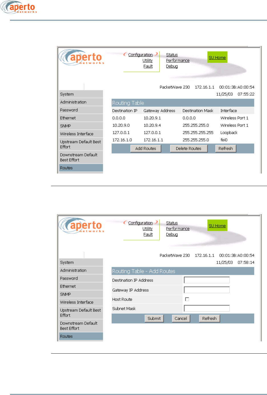
Chapter 6. The Web GUI
6–18
10004880 Rev. D1
Figure 6-14 Routing Table Page
Figure 6-15 Add Routes Page
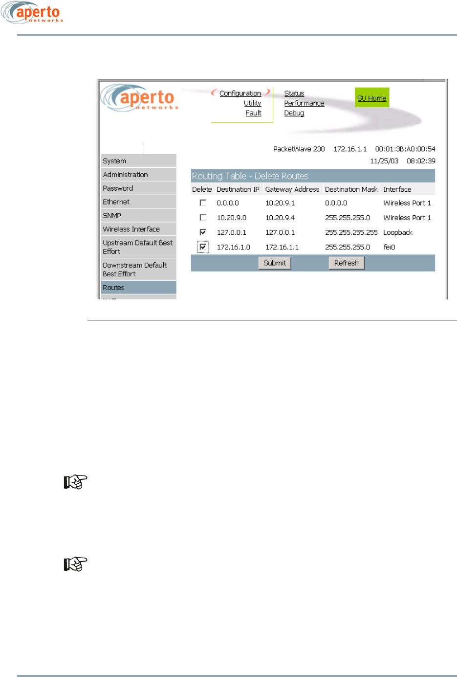
6–19
10004880 Rev. D1
Chapter 6. The Web GUI
Figure 6-16 Delete Routes Page
NAT Configuration
As shown in Figure 6-17, Figure 6-18, Figure 6-19, and Figure 6-20, there are four pages
that allow subscribers to configure NAT (Network Address Translation) routing for the sub-
scriber's LAN. These pages are accessible only when the Subscriber Unit is in NAT mode,
and are fully configurable at the Subscriber and ISP levels. Use these pages to configure
NAT parameters as appropriate for the local network. To move between the NAT pages,
click on the hyperlinks at the top of the pages.
NAT configuration should be performed by a network administrator.
On the NAT General page, specify the LAN IP Address and LAN Subnet Mask (required
fields), and any other parameters as desired. Then click Submit to implement the config-
urations. Two prompts will appear: to perform DHCP configuration; and to use the Upload
Configuration function (page 6-30) to make the NAT configuration permanent.
If you specify a port in the Divert HTTP to SU via port field, you will need to close your
browser and log on again using the URL with port—e.g., http://10.10.16.2:5002.
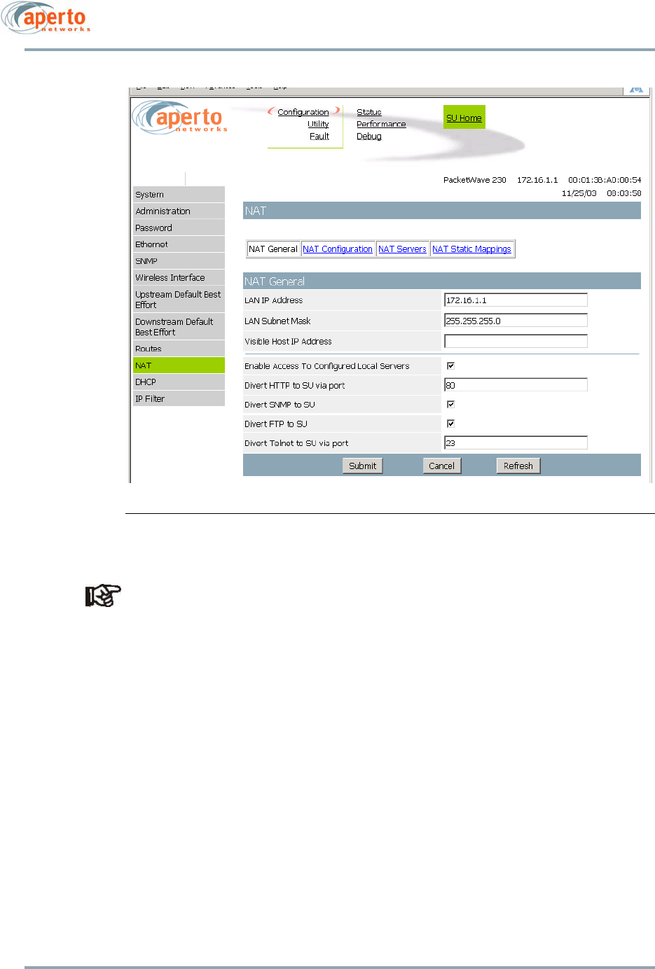
Chapter 6. The Web GUI
6–20
10004880 Rev. D1
Figure 6-17 NAT General Page
If the WEB HTTP interface is used to change the NAT IP address, please reset the Sub-
scriber Unit for it to take effect.
Use the NAT Configuration page to define local servers. All fields are required. After spec-
ifying the parameters for a particular server, click Add. The NAT Configuration page can
then be used to define another server.
Once a server has been added, it will be included in the list on the NAT Servers page. From
this page, servers can be deleted if desired. To delete a server, click on the box at the
beginning of the row describing the server; then click Submit.
The NAT Static Mappings page can be used to build a table of static mappings of local IP
addresses to global IP addresses. To add a static address mapping, click on the Add Map-
ping button and specify the local and global IP addresses. To remove a mapping from the
table, select the mapping in the table and click on the Delete Mapping button.
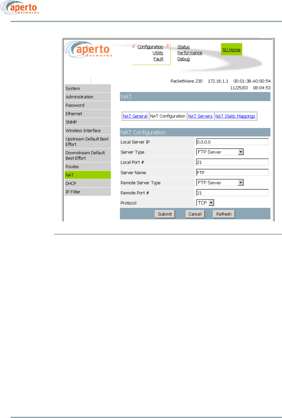
6–21
10004880 Rev. D1
Chapter 6. The Web GUI
Figure 6-18 NAT Configuration Page
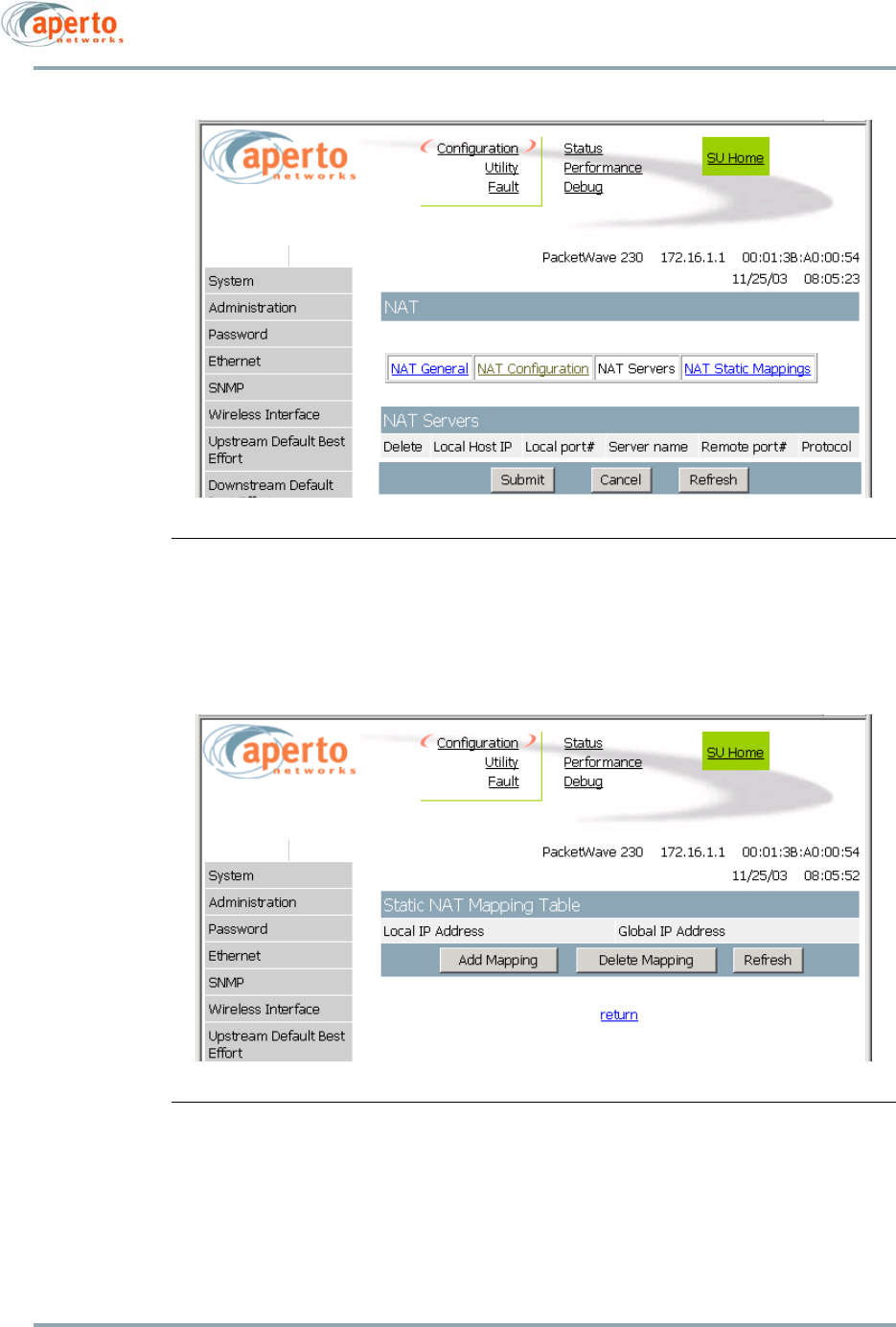
Chapter 6. The Web GUI
6–22
10004880 Rev. D1
Figure 6-19 NAT Servers Page
Figure 6-20 NAT Static Mappings Page
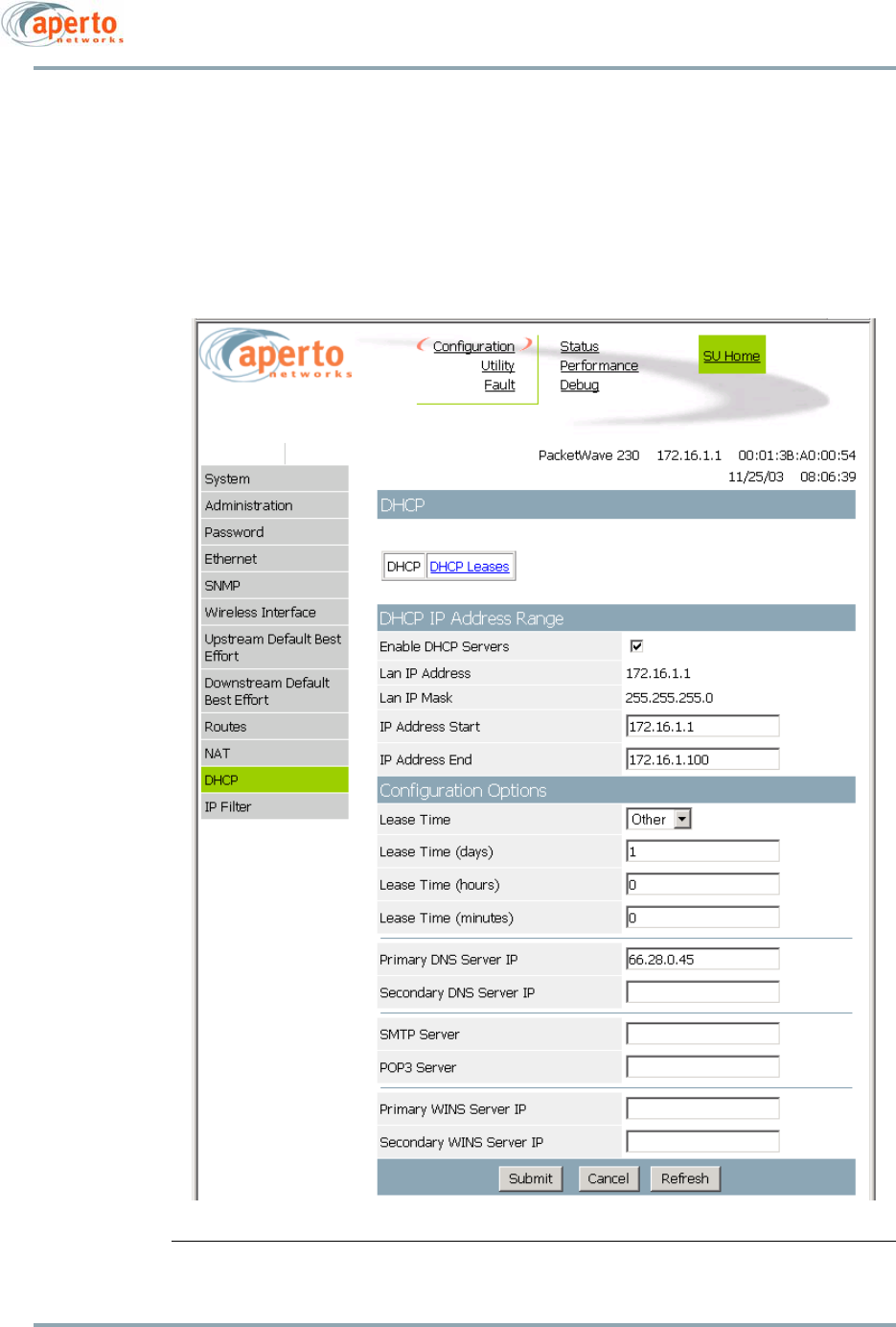
6–23
10004880 Rev. D1
Chapter 6. The Web GUI
DHCP Configuration
As shown in Figure 6-21 and Figure 6-22, there are two pages that allow subscribers to
configure the Subscriber Unit’s DHCP (Dynamic Host Configuration Protocol) server. These
pages are accessible only when the Subscriber Unit is in NAT or router mode, and are fully
configurable at the Subscriber and ISP levels.
Figure 6-21 DHCP General Configuration Page
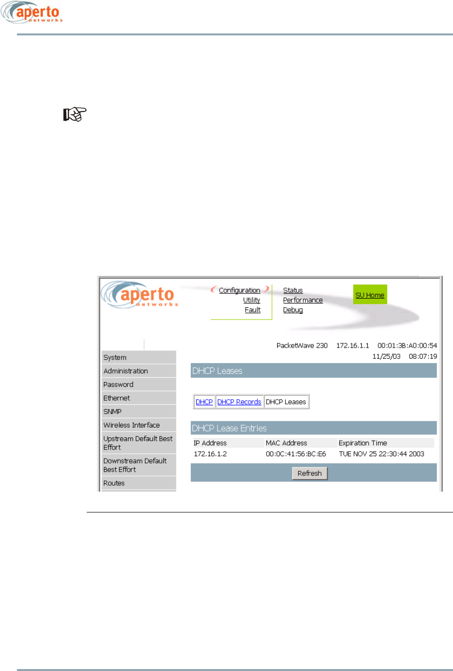
Chapter 6. The Web GUI
6–24
10004880 Rev. D1
Use these pages to configure DHCP parameters as appropriate for the subscriber’s LAN.
To move between the DHCP configuration pages, click on the hyperlinks at the top of the
pages.
DHCP configuration should be performed by a network administrator.
On the DHCP Configuration page, specify IP Address Start and IP Address End which will
define the DHCP address range (required), and any other configuration parameters as
desired; then click Submit.
On the DHCP Records page, assign and configure any individual IP address(es) as desired;
then click Submit.
To make the DHCP configuration part of the Subscriber Unit’s permanent configuration,
use the Upload Configuration function (page 6-30).
Figure 6-22 DHCP Leases Page
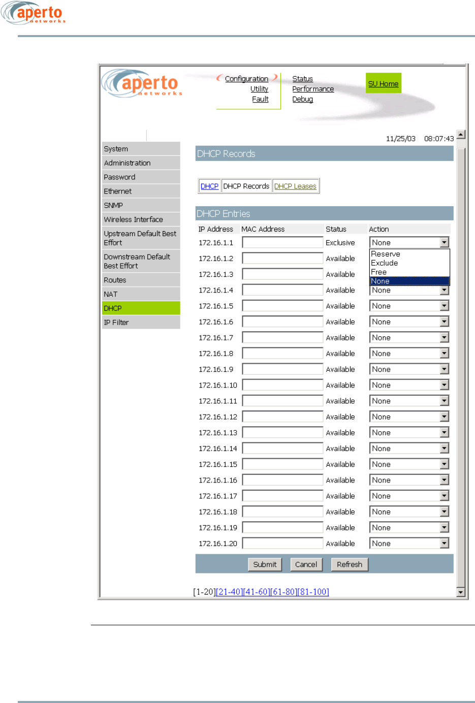
6–25
10004880 Rev. D1
Chapter 6. The Web GUI
Figure 6-23 DHCP Records Page
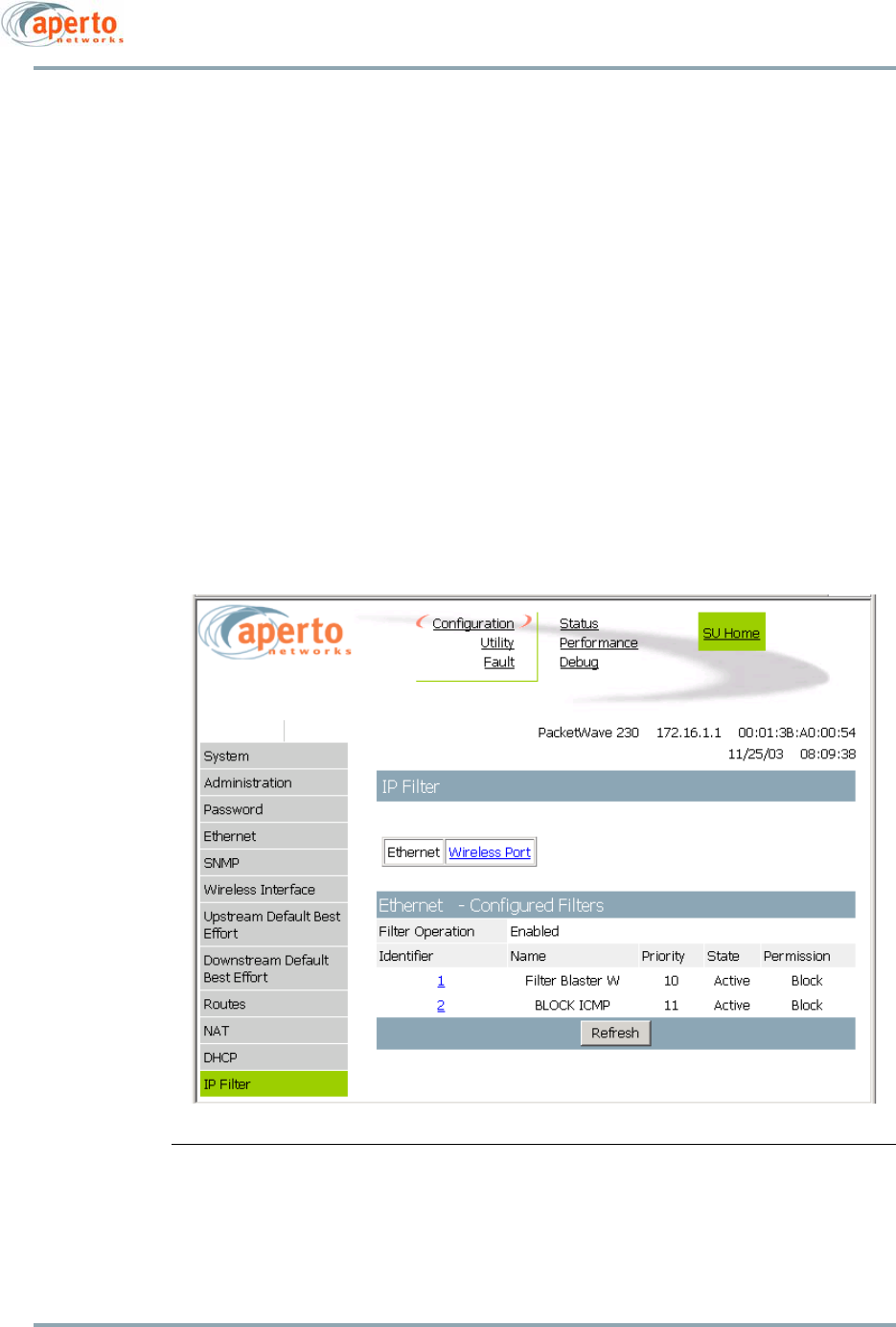
Chapter 6. The Web GUI
6–26
10004880 Rev. D1
IP Filter Configuration
IP Filter Configuration pages show any IP filters configured for the Subscriber Unit’s wire-
less and Ethernet interfaces. IP Filter List pages list all filters configured for a particular
interface, as shown in Figure 6-24. Hyperlinks at the top of the page allow either the Ether-
net or the wireless interface filters to be listed.
Each filter listed has an identifier number which also functions as a hyperlink to an IP Filter
Contents page. As illustrated in Figure 6-25, the IP Filter Contents page identifies the Layer
2 or Layer 3 parameters used in this particular filter. Hyperlinks at the top of the page
allow selection of Ethernet or wireless interface filter contents.
All IP Filter Configuration parameters are read-only. These pages are available only at the
ISP logon level.
Figure 6-24 IP Filter List Page (Ethernet)
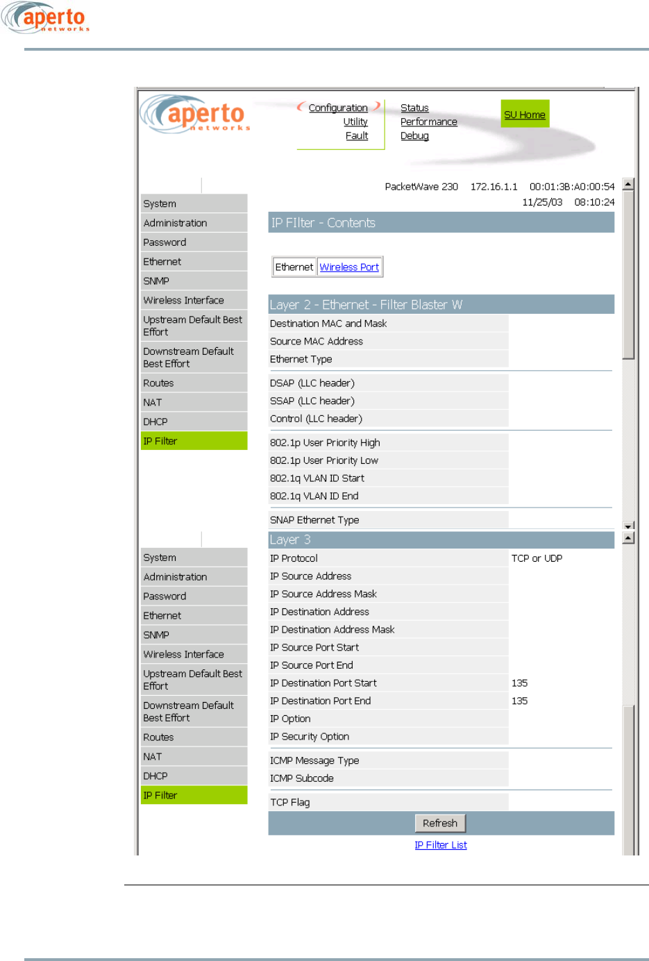
6–27
10004880 Rev. D1
Chapter 6. The Web GUI
Figure 6-25 IP Filter Content Page
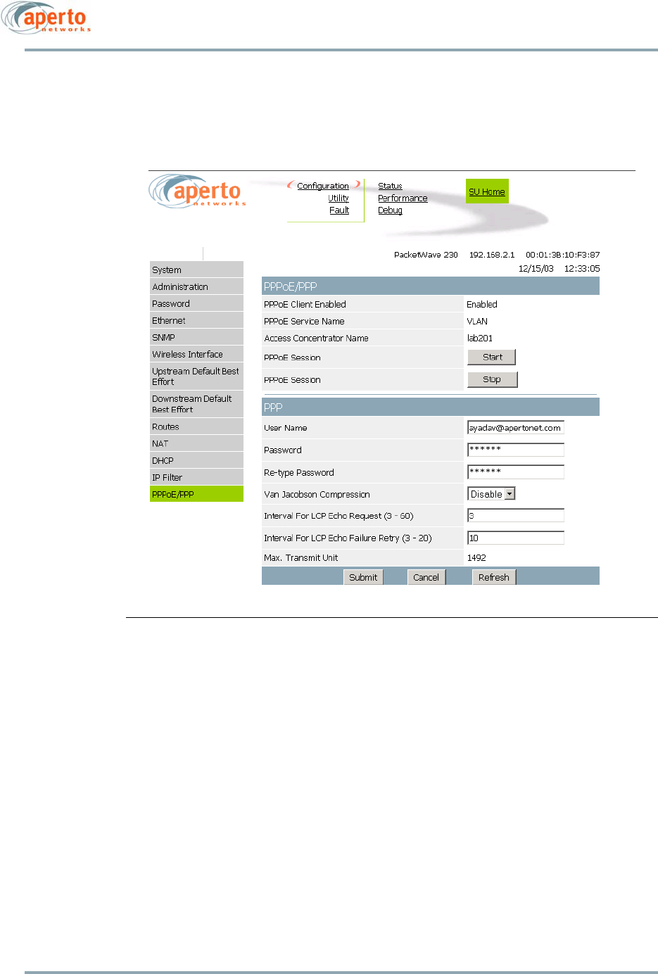
Chapter 6. The Web GUI
6–28
10004880 Rev. D1
PPPoE/PPP Configuration
The PPPoE/PPP Configuration page shown in Figure 6-26 is available at the ISP access
level when PPPoE is enabled. It is available only at the ISP logon level.
Figure 6-26 PPPoE/PPP Configuration Page, ISP Level
The PPPoE/PPP section includes the following PPPoE read-only client parameters:
• PPPoE Client Support Enable — Always enabled when this page is available.
• PPPoE Service Name and Access Concentrator Name — Optional fields set using the
Configuration Manager that can be used to identify an Access Concentrators.
The PPPoE/PPP section also includes Start and Stop buttons; use these buttons to start
or stop a PPPoE session.
The PPP section includes the following PPP client parameters:
• User name for authentication and Password for authentication — Specify the user
name and password for login to a remote ISP network
• Interval for LCP echo request — Specify how often Echo-Request messages are sent
on idle links to check the viability and integrity of the link.
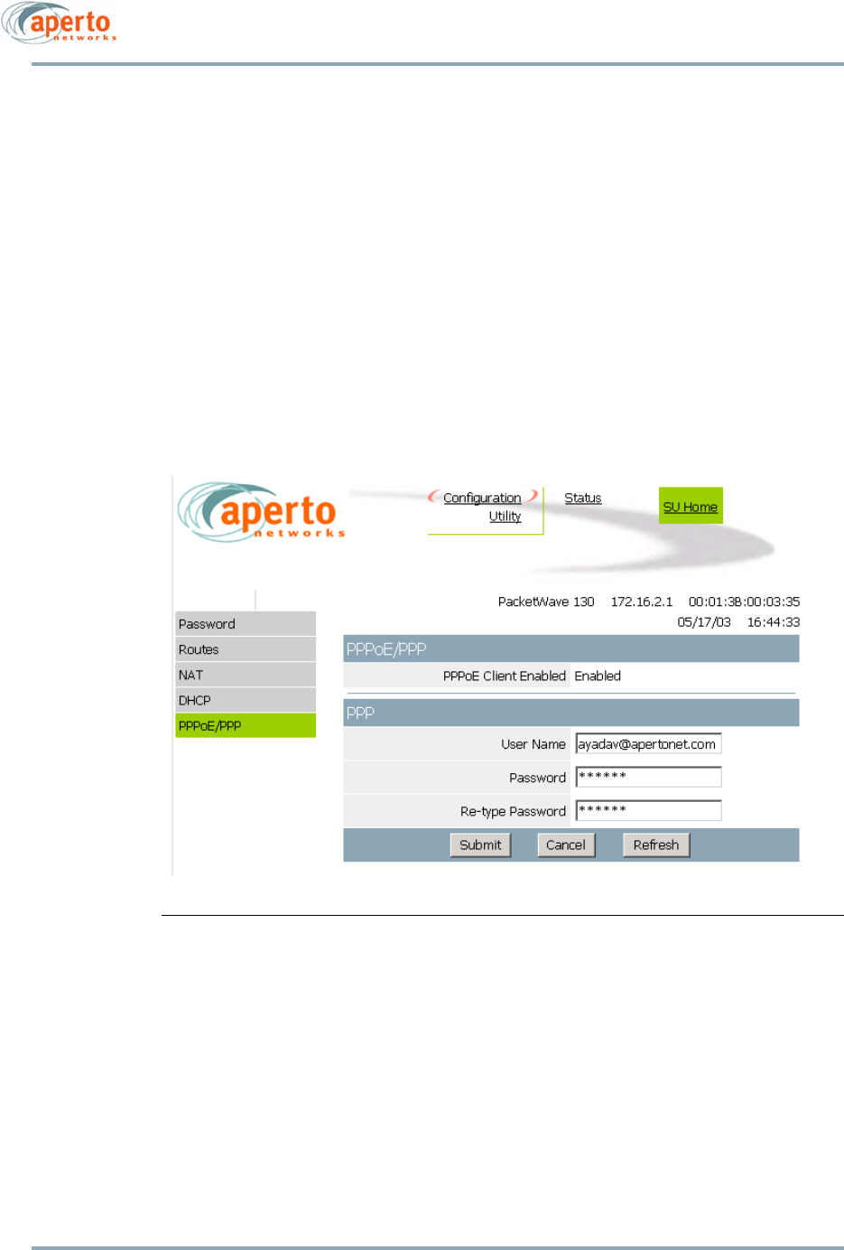
6–29
10004880 Rev. D1
Chapter 6. The Web GUI
• Maximum LCP echo failure retry — Specify the maximum number of times to retry
sending the LCP echo request if no replying packet is received.
• Maximum Transmit Unit (MTU) — Specify the maximum transmit size for a PPP
packet.
• Van Jacobson compression — Disable or enable Van Jacobson TCP/IP header com-
pression. (By reducing the size of the TCP/IP headers to as few as three bytes, Van
Jacobson compression can be a significant improvement on slow serial lines, par-
ticularly for interactive traffic.)
At the Subscriber level, the read-only PPPoE/PPP Configuration page shown in Figure 6-27
is available.
Figure 6-27 PPPoE/PPP Configuration Page, Subscriber Level
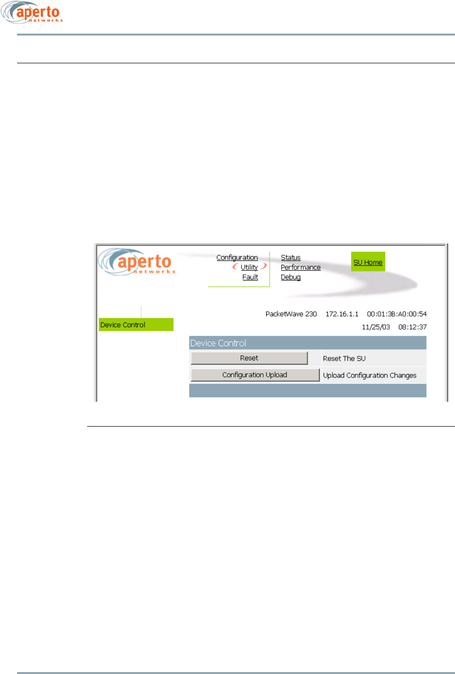
Chapter 6. The Web GUI
6–30
10004880 Rev. D1
Device Control Utility
The Device Control page, illustrated in Figure 6-28, provides access to a pair of functions:
• Resetting the PacketWave 200.
• Uploading configuration changes entered via the Web interface to the Subscriber
Unit’s configuration file on the TFTP server, making the changes part of the
Subscriber Unit’s permanent configuration.
The interface will prompt for confirmation before performing a selected function.
The full Device Control page is available only at ISP logon level. At the Subscriber logon
level, only the Upload Configuration function is available.
Figure 6-28 Device Control Page
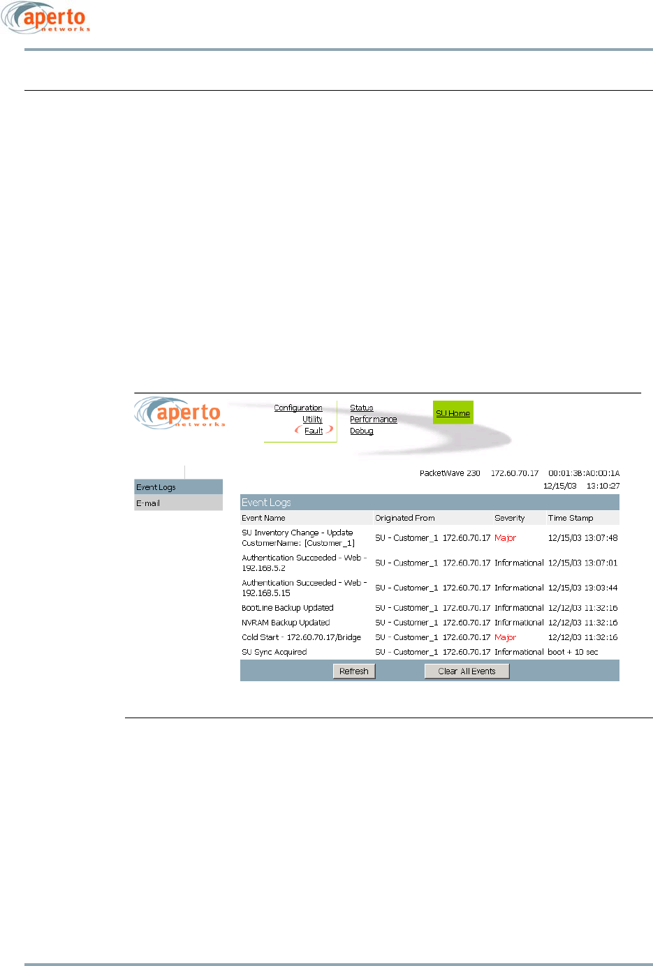
6–31
10004880 Rev. D1
Chapter 6. The Web GUI
Fault Reporting Pages
The subscriber fault reporting functions include an event log and E-mail configuration, as
shown in Figure 6-29 and Figure 6-30. These functions are available only at the ISP logon
level.
Event Log Page
The Event Log page, shown in Figure 6-29, includes all logable events reported by the
PacketWave 200. You can empty the log by clicking on the Clear All Events button.
NOTE: The data base used to generate the log is updated in real time. However,
the pages do not update dynamically; you must click on the Refresh button to
see later status.
Figure 6-29 Event Log Page
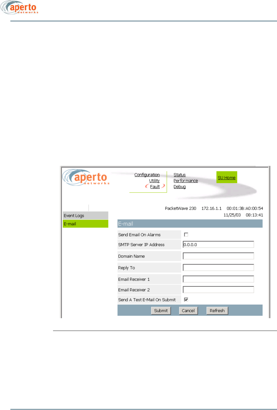
Chapter 6. The Web GUI
6–32
10004880 Rev. D1
E-mail Configuration Page
The E-mail Configuration page, shown in Figure 6-30, allows the viewing and altering of
E-mail event reporting parameters:
• Whether event reporting via E-mail is enabled or disabled.
• The address of the SMTP server.
• The E-mail domain name.
• Reply-to and receiver E-mail addresses.
• Whether a test E-mail will be sent when the Submit button is clicked on.
Click on the Submit button to activate any changes made on this page.
Figure 6-30 Email Page
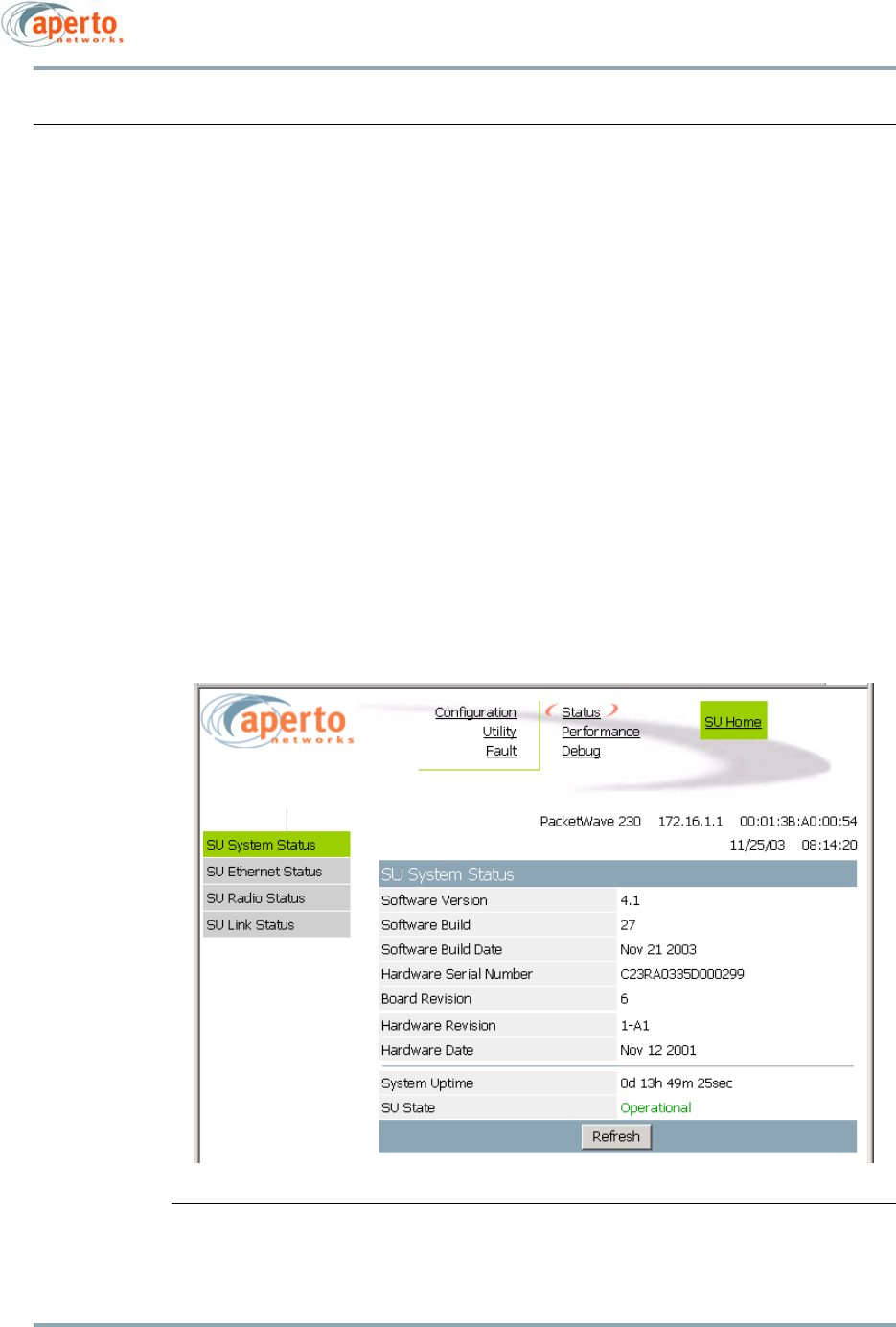
6–33
10004880 Rev. D1
Chapter 6. The Web GUI
Status Pages
The Web GUI include the following status pages:
• The System Status page, shown in Figure 6-31, identifies the PacketWave 200, its
software and hardware, and its current operational status.
•The Ethernet Status page, shown in Figure 6-32, shows the status, speed, and
duplex mode of the Ethernet link to the subscriber’s computer or network.
• The Radio Status page, shown in Figure 6-33, provides information and status
regarding the PacketWave 200 radio.
• The Link Status page, shown in Figure 6-34, provides information about the wire-
less link between the subscriber equipment and the base station.
• The PPPoE/PPP Status page, shown in Figure 6-35, provides information about the
PPPoE/PPP session. This page will only be available only if NAT and PPPoE have
been enabled.
System Status and PPPoE/PPP Status are available at both ISP and Subscriber levels;
Ethernet, Radio, and Link Status are available at the ISP level only.
Figure 6-31 System Status Page
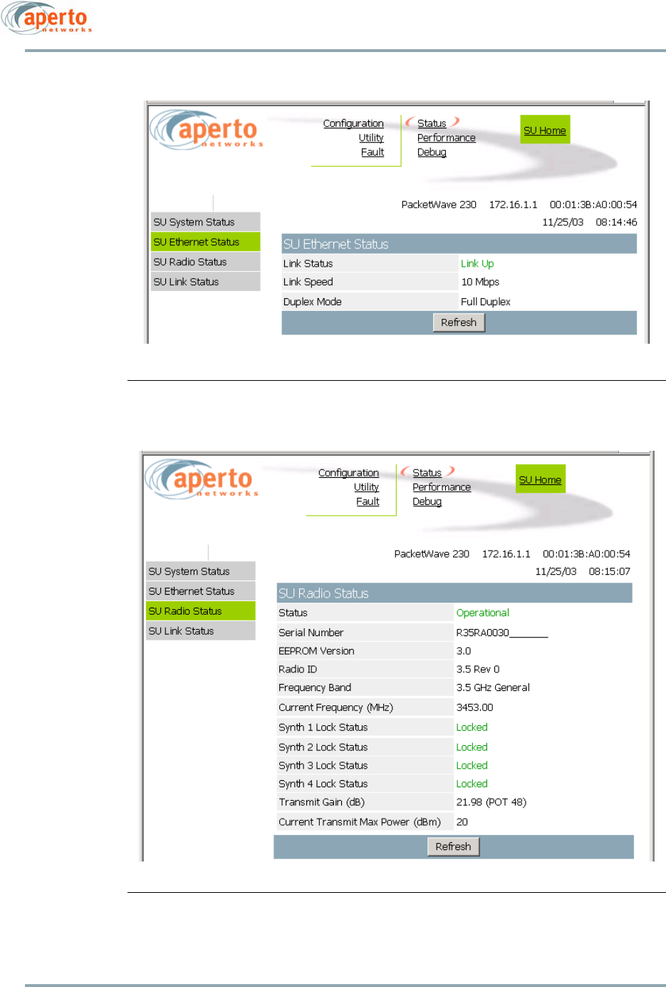
Chapter 6. The Web GUI
6–34
10004880 Rev. D1
Figure 6-32 Ethernet Status Page
Figure 6-33 Radio Status Page
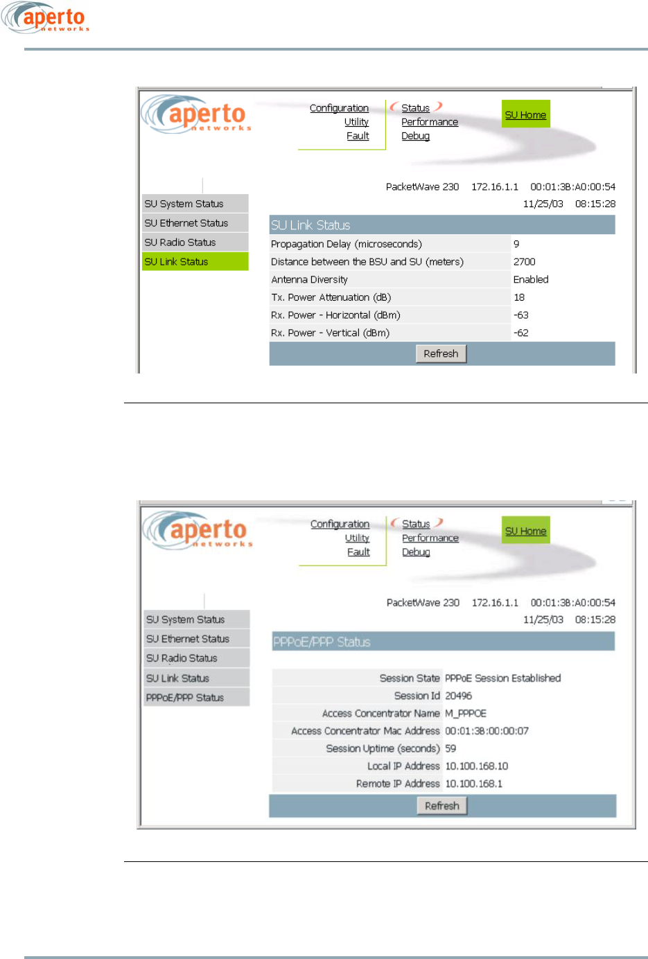
6–35
10004880 Rev. D1
Chapter 6. The Web GUI
Figure 6-34 Link Status Page
Figure 6-35 PPPoE/PPP Status Page
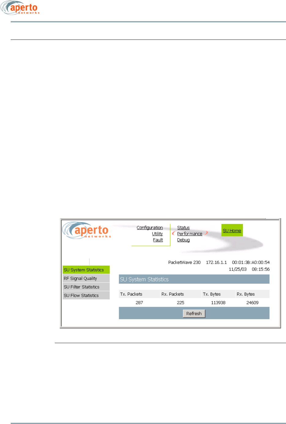
Chapter 6. The Web GUI
6–36
10004880 Rev. D1
Performance Pages
There are four performance pages:
• The SU System Statistics page (Figure 6-36) includes counts of packets and bytes
transmitted and received on the wireless link.
• The PPPoE Statistics page (Figure 6-37) shows PPPoE packet counts. This page will
only be available only if PPPoE and NAT have been enabled.
• The RF Signal Quality page (Figure 6-38) provides various measures of the quality
of the wireless signal. counters can be reset to 0 by clicking on the Reset Signal
Quality Counters button.
• The SU Filter Statistics page (Figure 6-39) provides counts of passed and blocked
packets. Hyperlinks allow selection of Ethernet or wireless interface statistics.
• The SU Flow Statistics page (Figure 6-40) provides upstream, downstream, and
upstream dropped packet counts for all defined service flows. Each Service Flow ID
serves as a hyperlink to a Service Flow Details page (Figure 6-41) providing detailed
flow statistics about the particular service flow. A hyperlink at the bottom of the
Service Flow Details page leads back to the Service Flow Summary page.
Performance pages are available at the ISP level only.
Figure 6-36 System Statistics Page
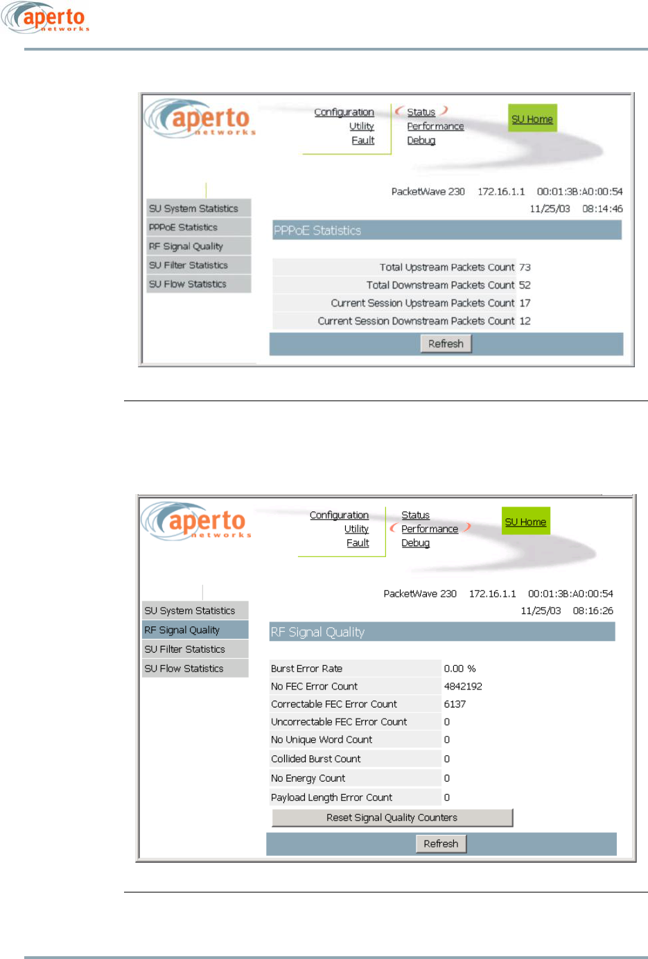
6–37
10004880 Rev. D1
Chapter 6. The Web GUI
Figure 6-37 PPPoE Statistics Page
Figure 6-38 RF Signal Quality Page
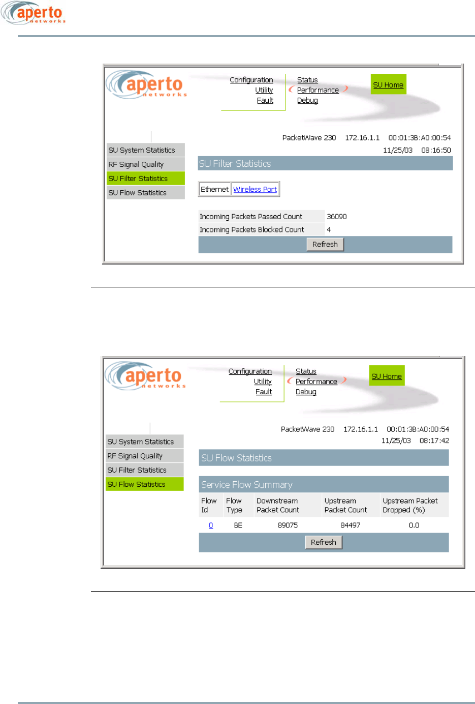
Chapter 6. The Web GUI
6–38
10004880 Rev. D1
Figure 6-39 Filter Statistics Page
Figure 6-40 Service Flow Summary Page
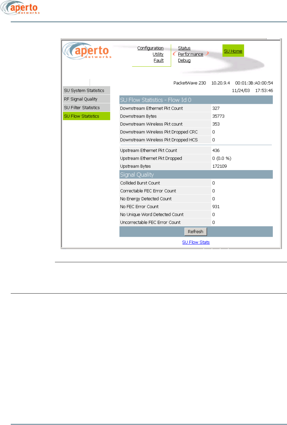
6–39
10004880 Rev. D1
Chapter 6. The Web GUI
Figure 6-41 Service Flow Details Page
Debug Page
The Debug CPE Page, illustrated in Figure 6-42, provides access to a wide range of perfor-
mance data and debug commands. It is available at the ISP level only, and provides
advanced troubleshooting capabilities for dealing with unusual installation or operation
problems.
Select performance displays and debug commands from the Commands drop-down menu
as desired. When a selection has been made, the content of the debug window will
change appropriately. To update the window, click Submit.
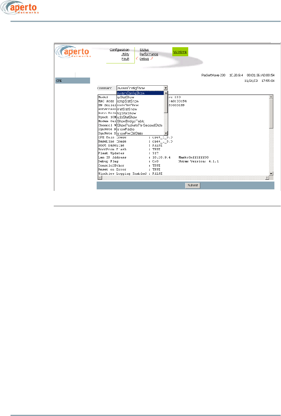
Chapter 6. The Web GUI
6–40
10004880 Rev. D1
Figure 6-42 Debug CPE Page

A–1
10004880 Rev. D1
Appendix
A
Specifications
General Specifications
Models
PacketWave 210 — Bridging mode; up to 5 hosts
PacketWave 220 — Bridging and NAT modes; up to 20 hosts
PacketWave 230 — Bridging, NAT, and IP routing modes; up to 254 hosts
Interfaces
Interface Box to PC/Hub — 10/100Base-T Ethernet, RJ-45 connector, standard Cat 5
Ethernet cable (crossover for connection to computer; straight-through for connection
to hub/switch)
Interface Box to Outdoor Unit — Ethernet plus power, shielded RJ-45 connector, shielded
Cat 5 or Cat 5E cable (outdoor rated); up to 50 m (165 ft) with Cat 5, or 100 m (330 ft)
with Cat 5E
Power
Power Requirement — 100 to 240 V ac, 47 to 63 Hz
Power Consumption — 30 Watts for Indoor and Outdoor Unit
Networking and Protocols
Bridging
DHCP server and client
NAT
VLAN

Appendix A. Specifications
A–2
10004880 Rev. D1
RF
Data Rates — from 64 kbps with burst mode up to 20 Mbps in a 6 MHz channel
Modulation — QPSK, 16 QAM
Management
Service Provider
Subscriber provisioning using Java-based WaveCenter Configuration Manager;
Windows 98/2000/Pro, Linux, and Sun Solaris 2.8 platforms
Embedded WaveCenter agent supporting SNMP and web browser
SNMP MIB (RFC 1157), MIB II (RFC 1213), Aperto Enterprise MIBs
Software updates via TFTP
Subscriber
Web-based interface for subscriber-side
DHCP server and NAT configuration
Installation Manager Utility
Facilitates antenna alignment process
Diagnostic Manager Utility
Provides diagnostic functions for troubleshooting subscriber equipment
LED Indicators
Interface Box — Power present, Power provided to ODU
Outdoor Unit — Wireless Transmit and Receive, Ethernet Link
Interface Box
Operating Temperature — 32 to 104 °F (0 to 40 °C)
Humidity — 10 to 90%, noncondensing
W x H x D 1x2x2.5 inches (2.5x5.5x6 cm)
Weight 0.5 lbs (0.23 kg)
Regulatory Approvals
FCC Class B
ETSI

A–3
10004880 Rev. D1
Appendix A. Specifications
Outdoor Unit Specifications
Mounting
Clamping bracket for pole with diameter of 1.5 inch, 2 inches, or 5 cm
Adjustable elevation
Environmental
Operating Temperature — -22 to 140 °F (-30 to 60 °C)
Storage Temperature — -40 to 257 °F (-40 to 125 °C)
Humidity — 0 to 100%
2.5 GHz Outdoor Unit
Frequency Range — 2500 to 2686 MHz; Maximum EIRP * — -35 dBm
Dimensions: W x H x D — 12.6 x 12.6 x 1.9 inches (32.0 x 32.0 x 4.8 cm)
3 dB Beamwidth — Azimuth 20°; Elevation 20°
Polarization — Horizontal and vertical
3.5 GHz Outdoor Unit
Frequency Range — 3300 to 3800 MHz; Maximum EIRP * — -38 dBm
Dimensions: W x H x D — 10.2 x 10.2 x 1.9 inches (25.9 x 25.9 x 4.8 cm)
3 dB Beamwidth — Azimuth 20°; Elevation 20°
Polarization — Horizontal and vertical
5.3 GHz Outdoor Unit
Frequency Range — 5250 to 5350 MHz; Maximum EIRP * — -24 dBm for UNII
Dimensions: W x H x D — 8.1 x 8.1 x 1.9 inches (20.6 x 20.6 x 4.8 cm)
3 dB Beamwidth — Azimuth 17°; Elevation 17°
Polarization — Horizontal and vertical
NOTE: Frequency Scanning with PacketWave 200 3.5 models may have errors if
the frequency range is the entire frequency band. Please divide the tests into
smaller ranges.
5.8 GHz Outdoor Unit
Frequency Range — 5725 to 5875 MHz; Maximum EIRP * — -38 dBm
Dimensions: W x H x D — 8.1 x 8.1 x 1.9 inches (20.6 x 20.6 x 4.8 cm)
3 dB Beamwidth — Azimuth 17°; Elevation 17°
Polarization — Horizontal and vertical

Appendix A. Specifications
A–4
10004880 Rev. D1
* The maximum EIRP varies depending on country regulations.
Contact Aperto Networks sales for more information.

B–1
10004880 Rev. D1
Appendix
B
Event Reporting
The PacketWave subscriber equipment can be configured to report events by any of sev-
eral means:
• E-mail event messages.
•SNMP traps.
• Logging to a Syslog server.
• Event log presented on request via the Web GUI.
Reportable events are identified in Table B-A.
Table B-A Events Reported
ID Fault Event Severity Description/Comments
1 AUTHENTICATION_FAIL Major Request not properly authenticated. Attached string specifies interface
(Web, CLI, or SNMP) and IP Address of requestor.
2 SYSTEM_WARM_START Major System has performed a warm start.
3 SYSTEM_COLD_START Major SU has received registration acknowledged message from BSU.
Attached string specifies IP Address of SU and operating mode
(bridge, router, NAT, or VLAN). String can also include:
“TxGain Not Calib'ed” (Radio gain is not calibrated)
“OvrPwr Not Calib'ed” (Radio Regulatory power is not calibrated)
13 CPE_SYNC_ACQUIRED Major SU acquired sync for the first time.
18 DHCP_FAILURE Major Attached string:
DHCPC:ERROR-No DHCP Offer
DHCPC: WARNING-Using Cached Data
DHCPC:ERROR - Param Failure
DHCPC:INVALID OFFER - no Config File/Server
DHCP FAILURE-USING CACHED DATA
ERROR adding default Gateway: <IP address>
DHCP Failure

Appendix B. Event Reporting
B–2
10004880 Rev. D1
19 CFG_DOWNLOAD_FAILURE Major Download or parsing of config file from TFTP server failed.
Attached string:
Fail download cfg file from primary TFTP server
Failed to download config file
Failed to parse config file
Failed to verify checksum
20 RAM_AVLBL_TOO_LOW Major Available RAM has gone below 1.9%.
Attached string: Current RAM availability (in 0.1%).
21 RAM_AVLBL_NORMAL Major Available RAM has returned to 1.9% or higher.
Attached string: Current RAM availability (in 0.1%).
24 RADIO_VOLT_REG_FAILED Major Voltage regulator on the radio board failed (non-PW200 radios only).
25 RADIO_VOLT_REG_CLEARE
D
Major Voltage regulator failure cleared (non-PW200 radios only).
26 RADIO_SYNTH_NOT_LOCKE
D
Major Frequency synthesizer on the radio lost lock. Attached string identifies
synthesizer.
27 RADIO_SYNTH_NOT_LOCKE
D_
CLEARED
Major Frequency synthesizer on the radio regained lock. Attached string iden-
tifies synthesizer.
30 DC12V_FAILED Major System power supply failed.
31 DC12V_CLEARED Major System power supply recovered from failure.
37 FLASH_AVLBL_SPACE_TOO_
LOW
Major Only for RAM0. Available system flash space has gone below 0.4%.
Attached string gives availability (in 0.1%).
38 FLASH_AVLBL_SPACE_NOR
MAL
Major Only for RAM0. Available system flash space has returned to 0.4% or
higher. Attached string gives availability (in 0.1%).
41 FILESYSTEM_CORRUPTED Major For RAM0 only. File system has become corrupted.
42 FILESYSTEM_CORRUPTION_
CLEARED
Major For RAM0 only. File system no longer corrupted.
43 EVENT_CODE_SMTP_CONN
ECT_FAILURE
Major Connection to SMTP Server cannot be established. Attached string
identifies the IP Address of the SMTP Server.
45 SW_WATCHDOG_RESET Major Software watchdog task detected an inactive/crashed task and forced
the wireless subsystem to reset. Attached string identifies problem by
numeric code (0 = System Memory Low; 1 = Daemon Suspended; 2 =
Assert Fail; 3 = Calls Stuck; 4 = WMAC stopped.
46 NAT_CONFIG_ERROR Warning Error configuring NAT; attached string gives IP address.
47 CURRENT_IMAGE_CORRUP
TED
Major System booted up from the baseline image (since the previous boot
process with the original image failed). Attached string identifies
image file name.
48 BSC_CPE_FAILED_
REGISTRATION
Major SU failed during registration.
49 DEFAULT_CONFIG_FILE_NO
T_
FOUND
Major DFS file is absent in the device.
51 CURRENT_CPE_STATE Info For Operational or Standby state only.
Table B-A Events Reported
ID Fault Event Severity Description/Comments

B–3
10004880 Rev. D1
Appendix B. Event Reporting
52 MEMORY_BUFFER_TOO_LO
W
Major A memory buffer critical to the system operation is almost full.
53 MEMORY_BUFFER_NORMA
L
Major A memory buffer is no longer almost full.
54 CFG_VERSION_CHECK_FAIL
URE
Major “Last_Cfg_Update_Version” defined in config file is later than the cur-
rent SW version; or “Last_Cfg_Update_Version” is not defined in con-
fig file. Attached string may be “Incompatible Config file version” or
“Config file version absent”.
55 DFS_VERSION_CHECK_FAIL
URE
Major “Config_Version” defined in DFS file is different from the current SW
version; or “Config_Version” is not defined in DFS file. Attached
string may be “Incompatible DFS file version” or “DFS file version
absent”.
56 CFG_UPLOAD_FAILURE Major Upload of config file to TFTP server failed.
57 CFG_UPLOAD_CHECKSUM_
FAILURE
Major Checksum verification failed for the config file upload.
65 MODEL_NUMBER_CHECK_
FAILURE
Major SU’s configured model number does not match actual functionality.
Attached string gives SU Mac Address and reason (“Model number not
supported”; “Model numbers not compatible”; “Incompatible model
and mode”; “Model number not configured”; “CPE mode not config-
ured”).
66 DHCP_Warning Warning DHCP not completely successful. String attached:
No IP record bound for <MAC Address>
Duplicated MAC address <MAC Address> found
Fail to add <MAC Address> to leased table
Dynamic Lease <IP Address> overridden.
Fail to configure <IP Address>
Exclude a reserved entry <IP Address>
IP entry <IP Address> not found.
Invalid parameter “X”
67 CFG_PARSE_FAILURE Major or
Warning
Config file can't be parsed correctly. String attached:
Error parsing config file
Unknown TLVs found in config file [This may happen when a
config file generated with the new software is loaded onto a sys-
tem using relatively older software]
Unknown WSS found in config file [TLVs that belong to an
unknown WSS are found in the config file]
68 EV_UPDATE_CPE_INVENTO
RY
Major Customer name has been changed dynamically. Attached string gives
SU customer name.
69 PPP_FAILURE Major PPP failed to establish a session (may be a result of LCP negotiation
failure or a result of CHAP authentication failure). Attached string:
“PPP authentication fails”
“PPP LAC call fails”
70 PPP_STATUS Info PPP link has gone up or down. Attached string:
“PPP link is up”
“PPP link is down”
71 FREQUENCY_CHANGE Major
or Info
SU radio frequency has been changed dynamically. Attached string
gives new frequency.
Severity is Info if the SU is not operational; Major otherwise.
74 PPPOE_SESSION_UP Info A PPPoE Session has come up. Attached string specifies “SESSION
ACTIVE:<SessionId #>”
Table B-A Events Reported
ID Fault Event Severity Description/Comments

Appendix B. Event Reporting
B–4
10004880 Rev. D1
75 PPPOE_OFFER_ERROR Warning No valid PPPoE Active Discovery Offer (PADO) was received in
response to a PPPoE Active Discovery Initiation (PADI) packet; or no
valid PPPoE Active Discovery Session-confirmation (PADS) was
received in response to a PPPoE Active Discovery Request (PADR)
packet. Attached string elaborates:
“Invalid Offer: Access Concentrator Name didn't match”
“Invalid Offer: Service Name didn't match”
“Invalid Offer: No Service Name in offer”
“No PPPoE Active Discovery Offer received”
“MAX PADI Retries exceeded-giving up”
“Timed out waiting for PADS”
76 PPPOE_SESSION_TERMINAT
E
Warning A PPPoE Session has terminated. Attached string indicates reason:
“Terminating PPPoE Session: PADT From Server”
“Terminating PPPoE Session: NMS Initiated”
“Terminating PPPoE Session: PPP Initiated”
77 ETH_LINK_AUTO_NEGOTIA
TE
Major Ethernet link failed to come up using a fixed speed and duplex setting
and has fallen back to Auto-Negotiate.
78 RADIO_INIT_ERROR Major SU only. Radio cannot be initialized. Attached string:
“Ctrl Error” (ODU interface issues)
“Bad Chksum” (incorrect checksum on serial EEPROM)
“Cfg Freq Invalid” (mismatch between configured frequency and
radio board)
“HFDD Not Supported” (configuring FDD mode on non-FDD
radio)
79 RADIO_CANNOT_HIT_MAX_
POWER
Major Radio board cannot reach maximum configured power. May be caused
by a combination of faulty (or very long) coaxial cable connection,
extremely hot weather, and/or bad calibration data.
80 RADIO_CANNOT_HIT_MAX_
POWER_CLEARED
Major Radio board which could not reach maximum configured power can
now do so.
81 SODU_AGC_TABLE_NOT_
CALIBRATED
Major The PW200 SU platform relies on accurate calibration of the receive
gain throughout the entire receive chain. If the table is not correctly cal-
ibrated or gets corrupted, the PW200 will have to fall back on default
receive power adjustment algorithm which may be far from optimal.
This problem does not stop a PW200 from becoming operational but
the downstream link quality may suffer.
82 FREQ_TABLE_NO_VALID_E
NTRY
Major SU’s frequency table is configured with invalid frequency/BSU ID.
83 HTML_UNZIP_ERROR Major Web GUI files on the flash are either missing or are corrupted. Attached
String:
“File Not Found”
“File Corrupted”
84 BOOTLINE_BACKUP_UPDAT
ED
Info Backup bootline parameters have been updated to bring them in sync
with the actual boot parameters.
85 BOOTLINE_RESTORED_FRO
M_
BACKUP
Major Main bootline parameters are corrupted; the system has fallen back to
backup boot parameters.
86 NVRAM_BACKUP_UPDATED Info Backup copy of NVRAM configuration parameters has been updated
to bring them in sync with actual NVRAM configuration.
87 NVRAM_RESTORED_FROM_
BACKUP
Major Main NVRAM configuration data is corrupted; the system has fallen
back on backup NVRAM configuration.
Table B-A Events Reported
ID Fault Event Severity Description/Comments

C–1
10004880 Rev. D1
Appendix
C
Diagnostic Manager
The Diagnostic Manager utility supports a range of diagnostic functions designed to help
isolate Subscriber Unit problems under direct supervision by Aperto personnel. It is not
intended for general use by subscribers or service providers.
Loading the Diagnostic Manager Software onto the PC
To load the Aperto Installation Manager (AIM) software onto the PC to be used to run the
Diagnostic Manager:
1. Obtain the CD distributed with your PacketWave 200 equipment, which includes
the Diagnostic Manager (DM) software plus Java software from SUN Microsystems.
2. If the Java Runtime Environment is not present on the PC, install it from the
PacketWave distribution CD (bsu/Software/Application/Support directory) or the
java.sun.com web site.
3. Run the file
setup.exe
from the /Software/Application/DiagnosticManager/<OS> direc-
tory (where
<OS>
is the operating system being used, such as
win32
). At the end of
this installation, a Diagnostic Manager icon will be placed on the PC’s desktop.
NOTE: Diagnostic (DM) is now combined with AIM. It does work with the same
interface protocol as AIM and therefore is included in the same package.
Running the Diagnostic Manager
To use the Diagnostic Manager:
1. Connect the PC to the PacketWave 200 as described under Connecting to the Pack-
etWave 200 on page 5-2.
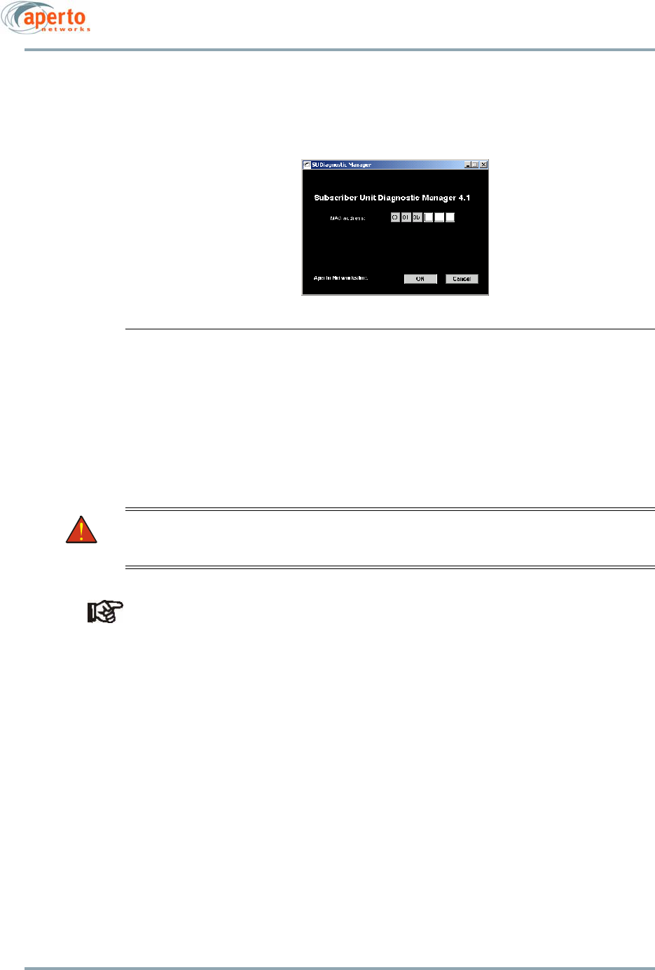
Appendix C. Diagnostic Manager
C–2
10004880 Rev. D1
2. Click on the Diagnostic Manager icon on the desktop to launch the utility. The win-
dow shown in Figure C-1 will be displayed.
3. Enter the MAC address of the PacketWave 200 as prompted; then click OK.
Figure C-1 Opening Diagnostic Manager Window
4. The Diagnostic Manager will open as shown in Figure C-2. The Diagnostic Manager
includes numerous diagnostic functions which can be initiated from the main
menu bar or from the command list area at the bottom of the window.
5. Execute diagnostic commands as directed by Aperto personnel. Command results
will be displayed in the text area below the menu bar.
WARNING: Diagnostic functions can seriously disrupt operation of the PacketWave
200. Use the Diagnostic Manager utility only under direct supervision by
Aperto personnel.
Make sure you close Diagnostic Manager (DM) sessions manually when using DM with
PacketWave 200 series products. If they are not closed, the data, which remains in the
memory will take up space needed by theSystem Upgrade Manager (SUM). SUM will give
a warning that there is not enough space and the process will not complete
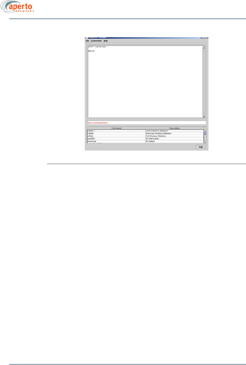
C–3
10004880 Rev. D1
Appendix C. Diagnostic Manager
Figure C-2 Diagnostic Manager

Appendix C. Diagnostic Manager
C–4
10004880 Rev. D1

D–1
10004880 Rev. D1
Appendix
D
Command Line Interface (CLI)
Each Subscriber Unit includes a simple command line interface (CLI) accessible via telnet.
The CLI is intended primarily for troubleshooting and debug use under direction of Aperto
personnel.
Accessing and Using the CLI
To access and use the Subscriber Unit’s command line interface:
1. Telnet to the Subscriber Unit’s IP address.
2. At the Login: prompt, enter the desired logon level: ISP or Subscriber. (There is also
a Debug logon level, which is reserved for Aperto use.)
NOTE: All CLI entries, including user name and password, are case-sensitive.
3. At the Password: prompt, enter the correct password for the specified logon level.
The CLI uses the same passwords as the Web interface. The default passwords
are isp and subscriber (case-sensitive). Passwords can be changed via the
WaveCenter Configuration Manager, the Web GUI, SNMP, and the CLI.
4. When the CLI# prompt appears, you are in the CLI.
a. For a list of commands, type ? (the ? will not appear on the screen; pressing
[Enter] is not necessary). The CLI will respond with a list of the available com-
mands groups.
b. To see the specific commands in a group, type the group name followed by ?
(again, the ? will not appear, and pressing [Enter] is not necessary).
c. To display information about the use of a specific commands, including com-
mand parameters, enter the command followed by ?.
5. If there is no activity on a connection for 30 minutes, the CLI will disconnect.
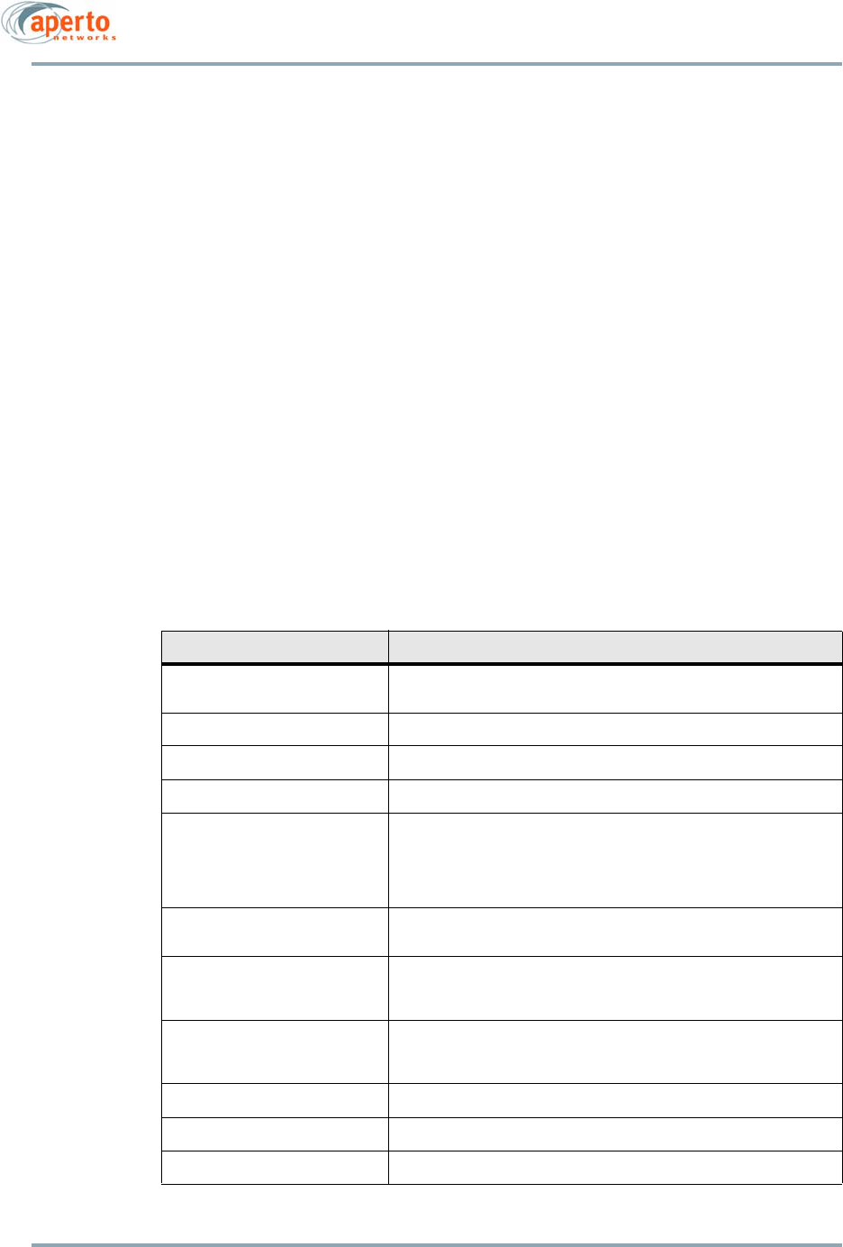
Appendix D. Command Line Interface (CLI)
D–2
10004880 Rev. D1
6. When you are finished with the CLI, end the Telnet session by entering the killTelnet
command or simply closing the Telnet application.
NOTE: One should type the command followed by an enter key. Then type the
“?” followed by an enter key. This will produce the desired effect.
Commands
Subscriber Unit CLI commands are defined in Table D-A. All commands are case-sensitive.
Error Messages
Error messages which may be returned by the Subscriber Unit CLI include the following:
• Error: Bad Command — command has been entered incorrectly.
• Error: Invalid Parameter — command has been entered incorrectly.
• Not applicable for SU — command applies to BSU CLI only.
• Passwords are not the same — when setting a password, two password entries do
not match.
Table D-A Subscriber Unit CLI Commands
Command Function
killTelnet Causes the CLI to terminate all current Telnet sessions connected at
port 5000.
reboot Reboots the Subscriber Unit.
set dhcpServer Does not apply to Subscriber Unit.
set vlan Sets vlan parameters.
set debug_passwd
set isp_passwd
set subs_passwd
These commands set passwords for Debug, ISP, and Subscriber logon.
CLI prompts for password to be entered twice (Enter Password:, then
Confirm Password:). New password is set only if the two entries are
identical, including case. Password cannot be set for higher logon level
than current logon.
show dhcp_server Shows the DHCP parameters, including IP address, subnet mask, and
gateway, TFTP servers, and config file name.
show config file Displays the Subscriber Unit’s configuration file in text format. File is
displayed one screen at a time; CLI prompts for key to be pressed to
display next screen.
show config frequency port 1
show config frequency all
Either command shows the center frequency for the Subscriber Unit’s
wireless port. The center frequency unit is 100 Hz; add two zeros for
frequency in Hz.
show config su_local_cfg Does not apply to Subscriber Unit.
show config vlan Shows the management VLAN parameters.
show status system Displays a broad range of system parameters.
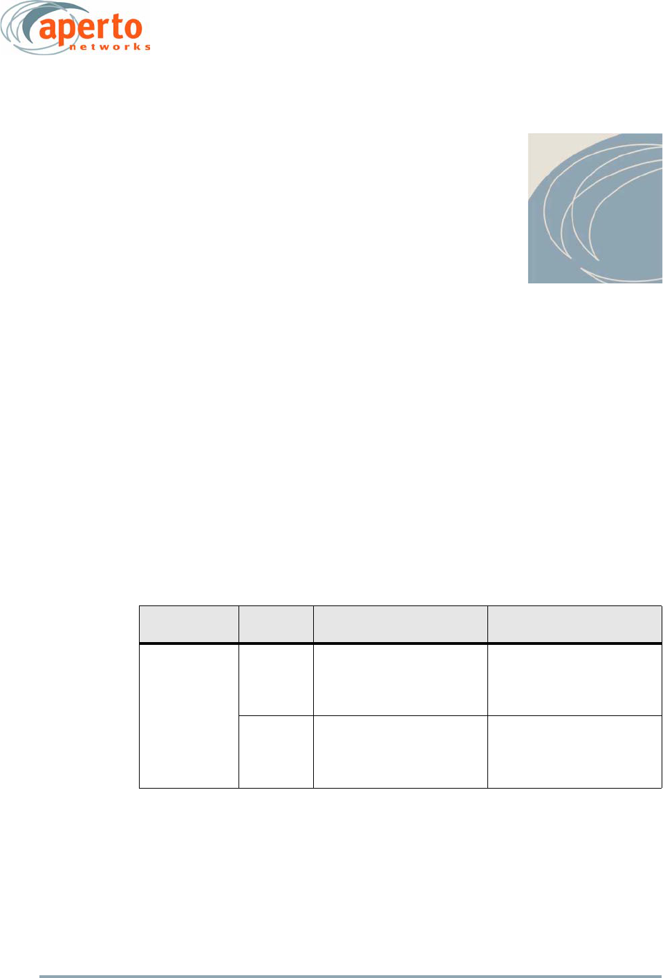
E–1
10004880 Rev. D1
Appendix
E
ODU Cables
Table E-A identifies specific cables and cable components that have been verified to meet
PacketWave 200 Series Subscriber Unit specifications for connection of the ODU to the
Interface Box.
NOTE: You can use other similar cables if you choose. However, only the cables
specified in Table E-A have been tested to the maximum lengths specified for
PacketWave installations.
Table E-B identifies accessories that will simplify cable installation.
Table E-A Radio Signal and Control Cables
Cable Use Maximum
Length
Cable Type Connectors
Interface Box to
ODU
50 m
(165 ft)
RG-6
Commscope 5741
Quad shielded, Copper covered
steel center conductor
Anixter #CS5741
Thomas & Betts SNS6QS
F connector for RG-6 Quad
shield
Snap and Seal (Environmental)
Anixter #182461
100 m
(330 ft)
RG-6
Belden 9290
Quad bare copper shielded, cop-
per center conductor
Anixter #B9290
Thomas & Betts SNS6QS
F connector for RG-6 Quad
shield
Snap and Seal (Environmental)
Anixter #182461

Appendix E. ODU Cables
E–2
10004880 Rev. D1
Table E-B Cable Accessories
Accessory Description
Modular Plug Crimping Tool
TYCO/AMP 2-231652-1
Anixter #143320
Hand crimp tool recommended for crimping
modular plugs to Cat5e cables.
Coax Cable Tester
Ideal Industries 62-202
Anixter #224414.
This is an example of a coax cable tester. (Many
alternatives are also available.)
Cat 5e Cable Tester
Ideal Industries 62-200 Linkmaster Cable Tester
Anixter #216776
This is an example of a Cat 5e cable tester. (Many
alternatives are also available.)

Index-1
10004880 Rev. D1
Index
A
AC power xiii, 1-2, 2-4, 2-6, 4-8, 4-11, 5-19, A-1
Consumption A-1
Access Concentrator 6-28
Access rights, SNMP 6-11
Administration Configuration page 6-7
Alignment — see Antenna alignment
Alignment mode, AIM 5-11
Alignment Window 5-9
Antenna alignment 1-3, 2-4, 3-1, 4-1, 4-3, 4-11, 4-12,
5-1, 5-4, 5-7, 5-9, 5-11 to 5-12, 5-15, 5-19,
5-20
Detuning 5-20
Graphs 5-11
Antenna alignment flag 5-12
Aperto Installation Manager (AIM) 1-1, 1-3, 2-5, 3-1,
4-1, 4-3, 4-11, 5-1 to 5-20
Connecting the PC 5-2
DHCP failure 5-20
Ethernet interface configuration 5-2, 5-3
Fails to connect 5-19
Hangs 5-19
Icon 5-1, 5-3
Installing on PC 5-1
IP address 5-2
Modes 5-4
Password 5-3, 5-9
Troubleshooting 5-19 to 5-20
Audio signal 1-3, 4-11, 5-11
Auto-alignment 1-1, 1-3, 4-1, 4-11, 5-4, 5-18
Automatic Frequency Selection (AFS) 2-4, 5-7, 5-11,
6-14
B
Base station 1-2, 1-3
Base station antenna 2-3
Sensitivity 5-20
Base Station Unit 4-12, 6-3, 6-14
WSS failure 5-20
Beam width 2-4, A-3
Best Effort (BE) class of service 6-16
Boot-up 2-5
Bridge/router modes 2-2, 6-8
Bridging 2-1, 2-2
BSU ID 5-6, 5-8, 6-14
BSU’s WSS number 5-6, 5-7
C
Cable Accessories E-2
Cables 1-2, 3-1, 3-2, 4-3, 4-9, 4-10, 5-19, 5-20, E-1 to
E-2
Cable length 1-2, 2-4, 3-1, 3-2
Cable routing 1-2, 3-1, 3-2
Connectors 3-2, 4-3, 4-8
Dressing cables 4-3, 4-8
Ethernet 1-3, 3-1, 4-3
Cancel button, Web GUI 6-5
Channel center frequency 5-20, 6-8, A-3, D-2
Channel Width 5-8, 6-14
Classifiers 6-16
Clear All Events button, Web GUI 6-31
Command line interface (CLI) 2-5, 6-7, 6-12, 6-13, D-1
to D-2
Error messages D-2
Login D-1, D-2
Passwords D-1, D-2
Commands, Debug 6-40
Community names, SNMP 6-11
Configuration 2-5, 2-7, 5-4, 5-5, 5-6 to 5-9, 6-5, 6-7 to
6-27
System configuration 1-1
Upload to TFTP server 2-5, 2-7, 6-1, 6-5, 6-30
Configuration file 1-1, 2-5, 2-7, 4-12, 6-30, D-2

Index-2
10004880 Rev. D1
Configuration Manager 1-1, 1-3, 2-5, 2-7, 4-12, 5-5,
5-8, 6-12, 6-13, 6-16
Platforms A-2
Connectivity View page 6-3
Connectors 4-1, 4-3, 4-8, 4-9, 4-10
Interface Box 4-2, 4-9, 4-10, A-1
Outdoor Unit (ODU) 4-2, 4-9
Continue with Setup mode, AIM 5-4, 5-15
Customer Name 5-6, 6-7
D
Debug page 6-40
Default Best Effort Configuration page 6-16, 6-17
Default gateway 1-3
Device Control page 6-30
DHCP 1-1, 1-3, 5-7, 6-1, 6-8, 6-20, 6-23 to 6-25
Address range 6-24
Server configuration 1-1, 6-23
DHCP client 2-6
DHCP Configuration pages 6-23 to 6-25
DHCP server 2-5, 2-6, 3-2, 4-12, 5-20, 6-23, D-2
Local 4-12
Diagnostic Manager 2-5, C-1 to C-2
Divert HTTP to SU via port 6-20
DNS server 1-3, 3-2
Documentation set xi
Dynamic updates, Web GUI 6-3
E
EIRP A-3
E-mail event reporting 6-31 to 6-32
Addresses 6-32
Domain name 6-32
Test 6-32
Environmental requirements A-3
Error messages B-1 to B-4
Ethernet 1-3
Hub 1-3, 3-1, 4-3, 4-10
Ethernet cable 1-2, 4-10, 5-2
Pinouts 4-10
Ethernet port 6-26, 6-36
Ethernet Status page 6-33, 6-34
Event Log, Web GUI
Clear All Events 6-31
Event log, Web GUI 2-7, 6-31, B-1
Event messages 2-7
Event reporting 2-7, B-1 to B-4
E-mail messages 2-7, B-1
F
Fault reporting 6-31 to 6-32, B-1
E-mail 6-31 to 6-32
Fault Reporting pages 6-31 to 6-32
Filter Statistics page 6-36, 6-38
Flow Statistics pages 6-36, 6-38, 6-39
Frequency bands 2-3, 5-6, 6-14, A-3
FTP 6-7
G
Gateway 1-3, 5-2, 5-7
Ground fault protection xiii, 4-11
Grounding xiii, 4-1, 4-6 to 4-7
Grounding lug, Outdoor Unit 4-7
H
Host unreachable 5-19
HTTP 6-20, 6-21
Hub 1-3, 3-1, 4-3, 4-10
Humidity A-3
Hyperlinks, Web GUI 6-5
I
Import CM database 1-1, 5-5
IM.DAT file 5-5, 5-6
Indoor Unit
Bridge/router modes 4-12
Initialization 4-12, 5-19
Installation Manager —
see Aperto Installation Manager (AIM)
Installation requirements 4-3
Cables 4-3
Connectors 4-3
Supplies 4-3
Tools 4-3
Installation Results window 5-14
Interface Box 1-2, 2-3, 2-4, 4-10
LEDs 2-6
Location 1-2, 3-1, 4-1, 4-8
Power 2-6
Internet Explorer 6-1, 6-2
IP address 1-1, 1-3, 4-12, 5-2, 5-7, 6-8, 6-20, 6-21, 6-24,
D-1
IP Filter Configuration pages 6-26 to 6-27
IP filters 6-26 to 6-27
IP routing 2-1, 2-2, 2-6, 6-18
ISP logon level 6-1, 6-2, 6-4, 6-7

Index-3
10004880 Rev. D1
J
Java 5-19, 6-1
Java Runtime Environment (JRE) 5-1, C-1
L
LAN connector 4-10
LAN IP address 6-20
LAN subnet mask 6-20
Layer 2 IP filters 6-26
Layer 3 IP filters 6-26
LCP echo request 6-29
LEDs 2-5, 2-6, 5-19
Lightning 1-2, 4-6, 4-11
Line-of-sight path 2-3, 3-1
Link Status mode, AIM 5-4, 5-16
Link Status page 6-33, 6-35
Local configuration 1-1, 5-7
Local Signal Strength graph 5-10, 5-11
M
MAC address 1-1, 5-19, 5-20, 6-8, C-1
Management 2-3 to 2-7, 6-1 to 6-40, A-2, C-1 to C-2
Management VLAN ID 5-8
Management VLAN priority 5-8
MIBs 2-7, A-2
Models 2-2, 2-6, A-1
Mounting 1-2, 4-3 to 4-5
Mounting brackets 1-2, 4-3 to 4-5
Alternate 4-5
Standard 4-4
N
NAT Configuration pages 6-20 to 6-22
NAT (Network Address Translation) 1-3, 2-1, 2-2, 2-6,
3-2, 4-12, 6-1, 6-20 to 6-22
Configuration 6-20 to 6-22
National Electrical Code (NEC) xiii, 4-7
Netscape 6-1, 6-2
Network mask 5-2, 5-7
O
OptimaLink technology 2-3
Outdoor Unit (ODU) 1-2, 2-3, 2-6
Beam width 2-4
Frequency bands 2-3
Grounding -xiii, 4-1, 4-6 to 4-7
Grounding lug 4-7
Location 1-2, 3-1, 4-1
Mounting 1-2, 2-3, 3-2, 4-1, 4-3, A-3
Power 2-4, 2-6, 4-8, 4-11
P
PacketWave CD 1-2, 2-7, 3-2, 4-6, 5-1, C-1
Password Configuration page 6-7
Passwords 5-9, 6-1, 6-2, 6-7, D-1
Command line interface (CLI) D-2
Default 6-2
Performance pages 6-36 to 6-39
Performance statistics 6-36, 6-37, 6-38, 6-39
Ping test 5-13, 5-19
Polarization/Antenna Diversity 5-8, 6-14
Pole clamp — see Mounting bracket
Power — see AC power
Power consumption A-1
PPPoE Statistics page 6-36, 6-37
PPPoE/PPP 2-1, 6-28 to 6-29, 6-33, 6-36
Configuration 6-28
PPPoE/PPP Configuration page 6-29
PPPoE/PPP Status page 6-33
Pre-provisioning 1-1, 1-3, 4-3, 4-11, 5-1, 5-4
Provision mode, AIM 5-4, 5-18
Q
QPSK 2-4, 5-11
Quick scan 5-11
R
Radio Status page 6-33, 6-34
Reboot D-2
Refresh button, Web GUI 6-5, 6-31
Reset 6-30, D-2
RF Signal Quality page 6-36, 6-37
Router 2-6
Routes Configuration page 6-18
Routing 1-1, 1-3, 2-1, 2-2, 2-6, 6-1, 6-18
Adding routes 6-18, 6-19
Deleting routes 6-18, 6-19
Routing Table page 6-18
S
Safety xii, xiii, 1-1, 4-3
Security 6-1, 6-2, 6-7
Logon levels 6-1
Passwords 6-1, 6-2, 6-7
Servers 2-6
Configuration 1-1
Local 6-21

Index-4
10004880 Rev. D1
Service Flow Details page 6-36, 6-39
Service Flow ID (SID) 6-16, 6-36
Service Flow Summary page 6-38
Service Flows 6-16 to 6-17, 6-36
Setup mode, AIM 5-4, 5-6
Signal quality 2-4, 3-1, 5-20
Signal scrambling 5-8
Site preparation 1-1, 3-1
SMTP 6-32
SNMP 2-5, 2-6, 2-7, 6-7, 6-11, 6-20, 6-21
Configuration 6-11
Managers 6-11
MIBs 2-7, A-2
Traps 2-7, 6-11, B-1
SNMP Configuration page 6-11
SNR graph 5-11, 5-12
Software releases 6-33
Specifications A-1 to A-3
Status indications 6-3, 6-7
Status pages 6-33 to 6-35
SU Inventory page, BSU 6-7
Submit button, Web GUI 6-5
Subnet addresses 3-2, 6-20
Subnet mask — see Network mask
Subscriber host computer 3-2, 4-1
Configuration 3-2, 4-1
Subscriber LAN 3-2, 4-1, 4-12, 6-8, 6-20, 6-21, 6-24
Subnet addresses 3-2, 6-20, 6-21
Subscriber logon level 6-1, 6-2, 6-4, 6-6, 6-7
Surge protection xiii, 1-2, 4-6, 4-11
Syslog 2-7, 6-8, B-1
System Configuration page 6-7
System Statistics page 6-36
System Status page 6-33, 6-35
T
TCP/IP 1-3
Telnet 6-20, 6-21, D-1, D-2
Temperature A-3
Test mode, AIM 5-4, 5-17
Testing 5-4, 5-12, 5-13, 5-14, 5-17, 5-18
text file 5-14
TFTP server 1-1, 2-5, 2-7, 4-12, 5-20, 6-1, 6-5, 6-30
Throughput test 5-13, 5-14, 5-19, 5-20
Tools needed 4-3
Traps 2-7, 6-11, B-1
Troubleshooting 6-40, B-1 to B-4, C-1 to C-2
Aperto Installation Manager (AIM) 5-19 to 5-20
U
Upload Configuration function 6-5, 6-7, 6-18, 6-20,
6-24, 6-30
Utility (Web GUI) 6-30
V
Van Jacobson compression 6-29
View SNR 5-11
VLAN 2-1, 5-8, 6-12, 6-13
VLAN pass-through 2-1
VLAN Classifier Configuration page 6-13
VLAN Configuration page 6-12
W
Warranty xiii, 1-2, 4-6
WaveCenter Configuration Manager —
see Configuration Manager
Web browsers 6-1
Web GUI 2-5, 2-7, 6-1 to 6-40, B-1
Access 6-2
Basic Elements 6-4
Cancel button 6-5
Connectivity view 6-3
Home page 6-3
Hyperlinks 6-5
Logon 6-2
Main Menu 6-4
Refresh button 6-5
Submenu 6-4
Submit button 6-5
Summary of functions 6-5
Wireless Interface Configuration page 6-14, 6-15
Wireless link 2-4, 2-6, 3-1, 6-36
Status 5-16, 6-3, 6-33
Testing 5-4, 5-13, 5-17
Wireless port 2-6, 6-14, 6-26, 6-36, D-2