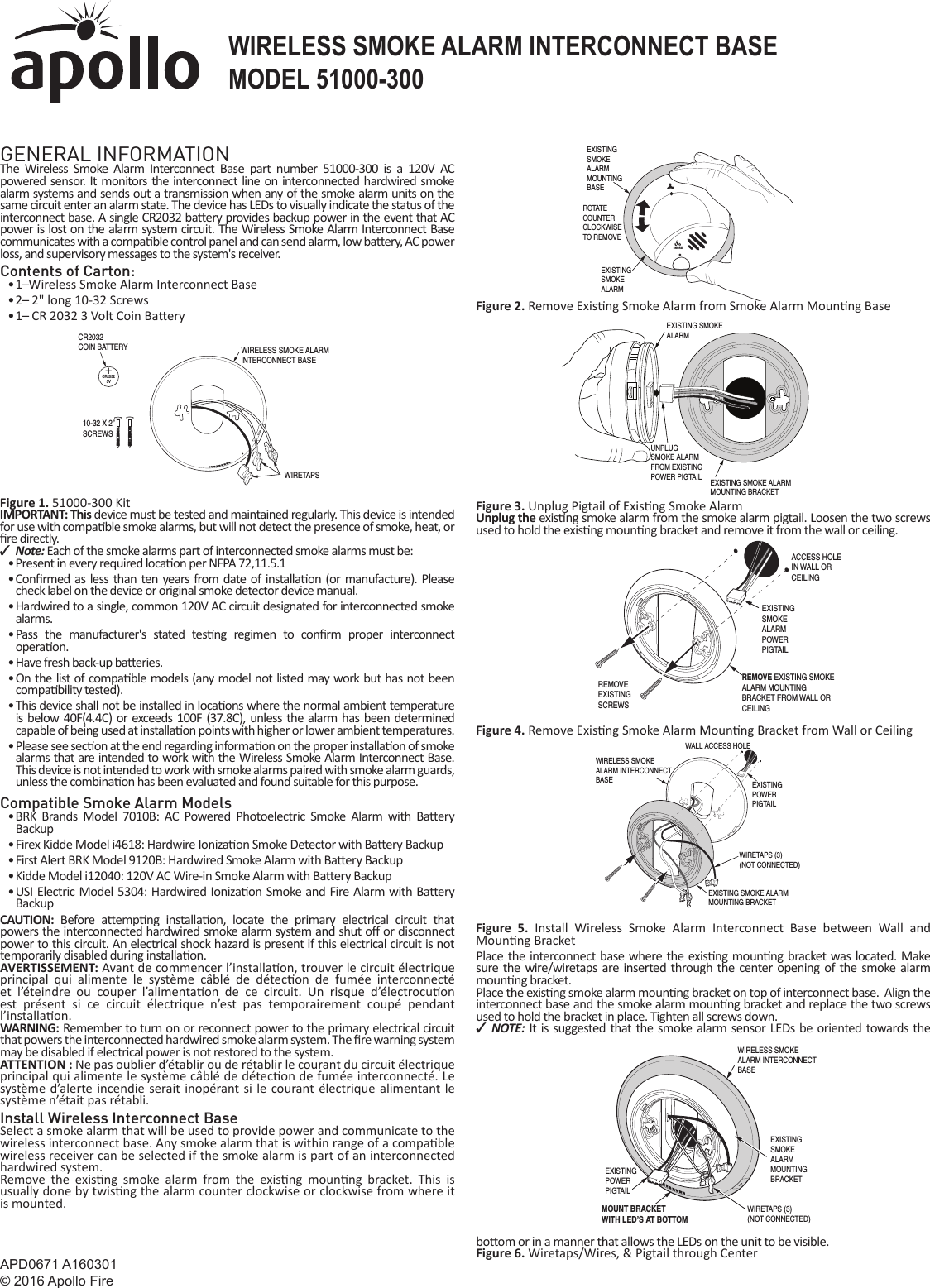
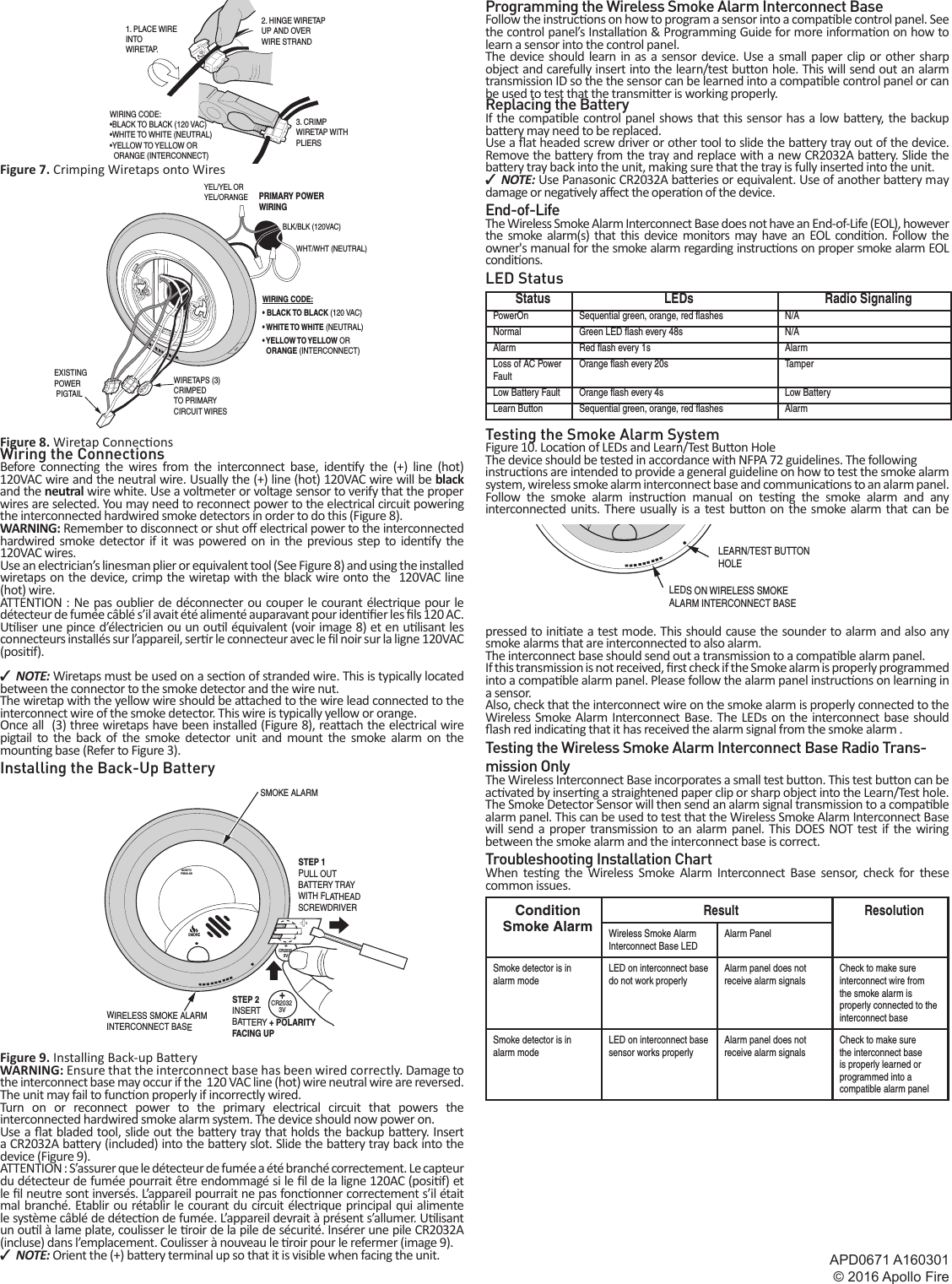
Apollo America 51000300 Wireless Smoke Alarm Interconnect Base User Manual Manual

Apollo America, Inc Wireless Smoke Alarm Interconnect Base Manual

Manual

APD0671 A160301© 2016 Apollo Fire Copyright © 2016 l 151000-300WIRELESS SMOKE ALARM INTERCONNECT BASEGENERAL INFORMATIONThe Wireless Smoke Alarm Interconnect Base part number 51000-300 is a 120V AC powered sensor. It monitors the interconnect line on interconnected hardwired smoke alarm systems and sends out a transmission when any of the smoke alarm units on the same circuit enter an alarm state. The device has LEDs to visually indicate the status of the interconnect base. A single CR2032 ba ery provides backup power in the event that AC power is lost on the alarm system circuit. The Wireless Smoke Alarm Interconnect Base communicates with a compa ble control panel and can send alarm, low ba  ery, AC power loss, and supervisory messages to the system's receiver.Contents of Carton:• 1   Wireless Smoke Alarm Interconnect Base• 2    2" long 10-32 Screws• 1    CR 2032 3 Volt Coin Ba eryFigure 1. 51000-300 KitIMPORTANT: This device must be tested and maintained regularly. This device is intended for use with compa ble smoke alarms, but will not detect the presence of smoke, heat, or  re directly. ✓Note: Each of the smoke alarms part of interconnected smoke alarms must be:• Present in every required loca on per NFPA 72,11.5.1• Con rmed as less than ten years from date of installa on (or manufacture). Please check label on the device or original smoke detector device manual.• Hardwired to a single, common 120V AC circuit designated for interconnected smoke alarms.• Pass the manufacturer's stated tes ng regimen to con rm proper interconnect opera on.• Have fresh back-up ba eries.• On the list of compa ble models (any model not listed may work but has not been compa bility tested).• This device shall not be installed in loca ons where the normal ambient temperature is below 40F(4.4C) or exceeds 100F (37.8C), unless the alarm has been determined capable of being used at installa on points with higher or lower ambient temperatures.• Please see sec on at the end regarding informa on on the proper installa on of smoke alarms that are intended to work with the Wireless Smoke Alarm Interconnect Base.This device is not intended to work with smoke alarms paired with smoke alarm guards, unless the combina on has been evaluated and found suitable for this purpose.Compatible Smoke Alarm Models• BRK Brands Model 7010B: AC Powered Photoelectric Smoke Alarm with Ba ery Backup• Firex Kidde Model i4618: Hardwire Ioniza on Smoke Detector with Ba ery Backup• First Alert BRK Model 9120B: Hardwired Smoke Alarm with Ba ery Backup• Kidde Model i12040: 120V AC Wire-in Smoke Alarm with Ba  ery Backup• USI Electric Model 5304: Hardwired Ioniza on Smoke and Fire Alarm with Ba ery BackupCAUTION:  Before a emp ng  installa on, locate the primary electrical circuit that powers the interconnected hardwired smoke alarm system and shut o  or disconnect power to this circuit. An electrical shock hazard is present if this electrical circuit is not temporarily disabled during installa on.AVERTISSEMENT: Avant de commencer l’installa on, trouver le circuit électrique principal qui alimente le système câblé de détec on de fumée interconnecté et l’éteindre ou couper l’alimenta on de ce circuit. Un risque d’électrocu on est présent si ce circuit électrique n’est pas temporairement coupé pendant l’installa on.  WARNING: Remember to turn on or reconnect power to the primary electrical circuit that powers the interconnected hardwired smoke alarm system. The  re warning system may be disabled if electrical power is not restored to the system.ATTENTION : Ne pas oublier d’établir ou de rétablir le courant du circuit électrique principal qui alimente le système câblé de détec on de fumée interconnecté. Le système d’alerte incendie serait inopérant si le courant électrique alimentant le système n’était pas rétabli.Install Wireless Interconnect BaseSelect a smoke alarm that will be used to provide power and communicate to the wireless interconnect base. Any smoke alarm that is within range of a compa ble wireless receiver can be selected if the smoke alarm is part of an interconnected hardwired system.Remove the exis ng smoke alarm from the exis ng  moun ng bracket. This is usually done by twis ng the alarm counter clockwise or clockwise from where it is mounted.Figure 2. Remove Exis ng Smoke Alarm from Smoke Alarm Moun ng BaseFigure 3. Unplug Pigtail of Exis ng Smoke AlarmUnplug the exis ng smoke alarm from the smoke alarm pigtail. Loosen the two screws used to hold the exis ng moun ng bracket and remove it from the wall or ceiling.Figure 4. Remove Exis ng Smoke Alarm Moun ng Bracket from Wall or CeilingFigure 5. Install Wireless Smoke Alarm Interconnect Base between Wall and Moun ng BracketPlace the interconnect base where the exis ng moun ng bracket was located. Make sure the wire/wiretaps are inserted through the center opening of the smoke alarm moun ng bracket.Place the exis ng smoke alarm moun ng bracket on top of interconnect base.  Align the interconnect base and the smoke alarm moun ng bracket and replace the two screws used to hold the bracket in place. Tighten all screws down. ✓NOTE:  It is suggested that the smoke alarm sensor LEDs be oriented towards the bo om or in a manner that allows the LEDs on the unit to be visible.Figure 6. Wiretaps/Wires, & Pigtail through Center PRINTER’S INSTRUCTIONS:INSTR,INSTL,APOLLO WIRELESS SMKE ALARM INTERCONNECT BASE - P/N: 10011636 X1- INK: BLACK - MATERIAL: 20 LB. MEAD BOND - SIZE: 8.500” X 11.000” - TOL. +/- .125”- SCALE: 1-1 -  FOLDING: FOLD 1X TO FINAL SIZE: 8.500" X 5.500"- FINISH WITH LOGO SHOWING+CR20323VWIRELESS SMOKE ALARMINTERCONNECT BASEWIRETAPSCR2032COIN BATTERY10-32 X 2” SCREWSSMOKEEXISTING SMOKEALARMMOUNTING BASE EXISTING SMOKEALARMROTAT ECOUNTERCLOCKWISETO REMOVEEXISTING SMOKEALARMEXISTING SMOKE ALARMMOUNTING BRACKETUNPLUGSMOKE ALARMFROM EXISTING POWER PIGTAILREMOVE EXISTING SMOKEALARM MOUNTING BRACKET FROM WALL ORCEILINGEXISTINGSMOKEALARMPOWERPIGTAILACCESS HOLEIN WALL OR CEILINGREMOVEEXISTINGSCREWSWIRELESS SMOKE ALARM INTERCONNECTBASEEXISTING SMOKE ALARMMOUNTING BRACKETEXISTINGPOWERPIGTAILWALL ACCESS HOLEWIRETAPS (3)(NOT CONNECTED)WIRELESS SMOKEALARM INTERCONNECTBASEEXISTING SMOKE ALARM MOUNTINGBRACKETEXISTING POWERPIGTAILWIRETAPS (3)(NOT CONNECTED)MOUNT BRACKETWITH LED’S AT BOTTOMApolloWIRELESS SMOKE ALARM INTERCONNECT BASEMODEL 51000-300
APD0671 A160301© 2016 Apollo Fire2 Copyright © 2016Figure 7. Crimping Wiretaps onto WiresFigure 8. Wiretap Connec onsWiring the ConnectionsBefore connec ng the wires from the interconnect base, iden fy the (+) line (hot) 120VAC wire and the neutral wire. Usually the (+) line (hot) 120VAC wire will be black and the neutral wire white. Use a voltmeter or voltage sensor to verify that the proper wires are selected. You may need to reconnect power to the electrical circuit powering the interconnected hardwired smoke detectors in order to do this (Figure 8).WARNING: Remember to disconnect or shut o  electrical power to the interconnected hardwired smoke detector if it was powered on in the previous step to iden  fy  the  120VAC wires.Use an electrician’s linesman plier or equivalent tool (See Figure 8) and using the installed wiretaps on the device, crimp the wiretap with the black wire onto the  120VAC line (hot) wire.ATTENTION : Ne pas oublier de déconnecter ou couper le courant électrique pour le détecteur de fumée câblé s’il avait été alimenté auparavant pour iden  er les   ls 120 AC.U liser une pince d’électricien ou un ou l équivalent (voir image 8) et en u lisant les connecteurs installés sur l’appareil, ser r le connecteur avec le  l noir sur la ligne 120VAC (posi f).  ✓NOTE: Wiretaps must be used on a sec on of stranded wire. This is typically located between the connector to the smoke detector and the wire nut.The wiretap with the yellow wire should be a ached to the wire lead connected to the interconnect wire of the smoke detector. This wire is typically yellow or orange.Once all  (3) three wiretaps have been installed (Figure 8), rea ach the electrical wire pigtail to the back of the smoke detector unit and mount the smoke alarm on the moun ng base (Refer to Figure 3).Installing the Back-Up BatteryFigure 9. Installing Back-up Ba eryWARNING: Ensure that the interconnect base has been wired correctly. Damage to the interconnect base may occur if the  120 VAC line (hot) wire neutral wire are reversed. The unit may fail to func on properly if incorrectly wired.Turn on or reconnect power to the primary electrical circuit that powers the interconnected hardwired smoke alarm system. The device should now power on.Use a  at bladed tool, slide out the ba ery tray that holds the backup ba ery. Insert a CR2032A ba ery (included) into the ba ery slot. Slide the ba ery tray back into the device (Figure 9).ATTENTION : S’assurer que le détecteur de fumée a été branché correctement. Le capteur du détecteur de fumée pourrait être endommagé si le  l de la ligne 120AC (posi f) et le  l neutre sont inversés. L’appareil pourrait ne pas fonc onner correctement s’il était mal branché. Etablir ou rétablir le courant du circuit électrique principal qui alimente le système câblé de détec on de fumée. L’appareil devrait à présent s’allumer. U lisant un ou l à lame plate, coulisser le  roir de la pile de sécurité. Insérer une pile CR2032A (incluse) dans l’emplacement. Coulisser à nouveau le  roir pour le refermer (image 9).  ✓NOTE: Orient the (+) ba ery terminal up so that it is visible when facing the unit.Programming the Wireless Smoke Alarm Interconnect BaseFollow the instruc ons on how to program a sensor into a compa ble control panel. See the control panel’s Installa on & Programming Guide for more informa on on how to learn a sensor into the control panel.The device should learn in as a sensor device. Use a small paper clip or other sharp object and carefully insert into the learn/test bu on hole. This will send out an alarm transmission ID so the the sensor can be learned into a compa ble control panel or can be used to test that the transmi er is working properly.Replacing the BatteryIf the compa ble control panel shows that this sensor has a low ba ery, the backup ba ery may need to be replaced.Use a  at headed screw driver or other tool to slide the ba ery tray out of the device. Remove the ba ery from the tray and replace with a new CR2032A ba ery. Slide the ba ery tray back into the unit, making sure that the tray is fully inserted into the unit. ✓NOTE: Use Panasonic CR2032A ba eries or equivalent. Use of another ba ery may damage or nega vely a ect the opera on of the device.End-of-LifeThe Wireless Smoke Alarm Interconnect Base does not have an End-of-Life (EOL), however the smoke alarm(s) that this device monitors may have an EOL condi on. Follow the owner's manual for the smoke alarm regarding instruc ons on proper smoke alarm EOL condi ons.LED StatusStatus LEDs Radio SignalingPowerOn Sequential green, orange, red fl ashes N/ANormal Green LED fl ash every 48s N/AAlarm Red fl ash every 1s AlarmLoss of AC Power FaultOrange fl ash every 20s TamperLow Battery Fault Orange fl ash every 4s Low BatteryLearn Button Sequential green, orange, red fl ashes AlarmTesting the Smoke Alarm SystemFigure 10. Loca on of LEDs and Learn/Test Bu  on HoleThe device should be tested in accordance with NFPA 72 guidelines. The followinginstruc ons are intended to provide a general guideline on how to test the smoke alarm system, wireless smoke alarm interconnect base and communica ons to an alarm panel.Follow the smoke alarm instruc on manual on tes ng the smoke alarm and any interconnected units. There usually is a test bu on on the smoke alarm that can be pressed to ini ate a test mode. This should cause the sounder to alarm and also any smoke alarms that are interconnected to also alarm.The interconnect base should send out a transmission to a compa ble alarm panel. If this transmission is not received,   rst check if the Smoke alarm is properly programmed into a compa ble alarm panel. Please follow the alarm panel instruc ons on learning in a sensor.Also, check that the interconnect wire on the smoke alarm is properly connected to the Wireless Smoke Alarm Interconnect Base. The LEDs on the interconnect base should  ash red indica ng that it has received the alarm signal from the smoke alarm . Testing the Wireless Smoke Alarm Interconnect Base Radio Trans-mission OnlyThe Wireless Interconnect Base incorporates a small test bu on. This test bu on can be ac vated by inser ng a straightened paper clip or sharp object into the Learn/Test hole. The Smoke Detector Sensor will then send an alarm signal transmission to a compa ble alarm panel. This can be used to test that the Wireless Smoke Alarm Interconnect Base will send a proper transmission to an alarm panel. This DOES NOT test if the wiring between the smoke alarm and the interconnect base is correct.Troubleshooting Installation ChartWhen tes ng the Wireless Smoke Alarm Interconnect Base sensor, check for these common issues.ConditionSmoke AlarmResult ResolutionWireless Smoke Alarm Interconnect Base LEDAlarm PanelSmoke detector is in alarm modeLED on interconnect base do not work properlyAlarm panel does not receive alarm signalsCheck to make sure interconnect wire from the smoke alarm is properly connected to the interconnect baseSmoke detector is in alarm modeLED on interconnect base sensor works properlyAlarm panel does not receive alarm signalsCheck to make sure the interconnect base is properly learned or programmed into a compatible alarm panelEXISTING POWER PIGTAILWIRETAPS (3)CRIMPED TO PRIMARYCIRCUIT WIRESWIRING CODE:• BLACK TO BLACK (120 VAC)• WHITE TO WHITE (NEUTRAL)• YELLOW TO YELLOW OR  ORANGE (INTERCONNECT)PRIMARY POWERWIRINGWHT/WHT (NEUTRAL)BLK/BLK (120VAC)YEL/YEL ORYEL/ORANGE+CR20323VMOVE TOFRESH AIRSMOKE+CR20323VSTEP 1PULL OUTBATTERY TRAYWITH FLATHEADSCREWDRIVERSTEP 2INSERT BATTERY + POLARITYFACING UPWIRELESS SMOKE ALARMINTERCONNECT BASESMOKE ALARM LEDS ON WIRELESS SMOKEALARM INTERCONNECT BASELEARN/TEST BUTTONHOLE1. PLACE WIRE INTOWIRETAP.2. HINGE WIRETAPUP AND OVER WIRE STRAND3. CRIMPWIRETAP WITHPLIERSWIRING CODE:•BLACK TO BLACK (120 VAC)•WHITE TO WHITE (NEUTRAL) •YELLOW TO YELLOW OR  ORANGE (INTERCONNECT)
APD0671 A160301© 2016 Apollo Fire Copyright © 2016 l 3Specifi cationsInput Power 120VAC 50/60Hz 12WBackup Power 3-Volt CR2032 Battery or EquivalentBackup Battery Life >8 yearsOperating Temperature 32°F to 122°F (0°C to 50°C)Operating Humidity 5–95% RH non-condensingCompatibility ADT Lynx and ADT VistaWireless Signal Range 350ft (110m)Supervisory Interval 70 minutesCertifi cation FCC/IC and ETLFCC NoticeThis device complies with Part 15 of the FCC’s Rules. Opera on is subject to the following two condi ons: 1 This device may not cause harmful interference, and 2 This device must accept any interference received, including interference that may cause undesired opera on. This equipment has been tested and found to comply with the limits for a Class B digital device, pursuant to Part 15 of the FCC Rules. These limits are designed to provide reasonable protec on against harmful interference in a residen al installa on. This equipment generates, uses and can radiate radio frequency energy and, if not installed and used in accordance with the instruc  ons, may cause harmful interference to radio communica  ons. However, there is no guarantee that interference will not occur in a par  cular installa on. If this equipment does cause harmful interference to radio or television recep on, which can be determined by turning the equipment o  and on, the user is encouraged to try to correct the interference by one or more of the following measures:  ✓Reorient or relocate the receiving antenna.  ✓Increase the separation between the equipment and receiver.  ✓Connect the equipment into an outlet on a circuit different from that to which the receiver is connected.  ✓Consult the dealer or an experienced radio/TV technician for help. To satisfy FCC/IC RF exposure safety requirements, a separation distance of 20 cm or more should be maintained between this device and person’s body (excluding extremities: hands, wrists, feet, and ankles).NOTE: Any changes or modi ca ons not expressly approved by the party responsible for compliance could void the user’s authority to operate this equipment.Industry Canada (IC) ComplianceThis device complies with Industry Canada license-exempt RSS standard(s). Opera on is subject to the following two condi ons: (1) this device may not cause interference, and (2) this device must accept any interference, including interference that may cause undesired opera on of the device. Le présent appareil est conforme aux CNR d’Industrie Canada applicables aux appareils radio exempts de licence. L’exploita on est autorisée aux deux condi ons suivantes: 1 l’appareil ne doit pas produire de brouillage, et 2 l’u lisateur de l’appareil doit accepter tout brouillage radioélectrique subi, même si le brouillage est suscep ble d’en comprome  re le fonc onnement.This Class B digital apparatus complies with Canadian ICES-003. Cet appareil numérique de la classe B est conforme à la norme NMB-003 du Canada. Apollo25 Corporate DriveAuburn Hills, MI 48326 USATEL: +1-248-332-3900FAX: +1-248-332-8807www.apollo- re.com                          10011636 X1
APD0671 A160301© 2016 Apollo Fire25 Corporate DriveAuburn Hills, Michigan 48326+1 (248) 332-3900  FAX: +1 (248) 332-8807www.apollo-re.com • SalesUSA@apollo-re.com

Navigation menu