Apple EarlierPowerMac 0309179AEXTVDOCONII User Manual External Video Connector Getting Started
User Manual: Apple EarlierPowerMac AppleExternalVideoConnector-GettingStarted
Open the PDF directly: View PDF ![]() .
.
Page Count: 63

When you install the Apple External Video Connector Kit,
you add a video connector (sometimes called a monitor-out
port) to your computer. You can connect a second monitor,
the Apple Presentation System, or a liquid crystal display
(LCD) panel to the external video connector.
1
CHAPTER
1
Getting Started
Do you have what you need?
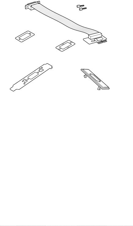
Check your package to make sure you have the external
video connector assembly, large metal bracket, plastic access
cover, two small metal brackets, and two jack nuts.
You also need a screwdriver to open your computer.
External video
connector assembly
Large metal bracket
Small metal bracket
Plastic access cover
Jack nuts
Small metal bracket with ribs
2Chapter 1

What you do next depends on what type of computer you
have:
mIf you have a 5400 series Macintosh computer, such as the
Macintosh Performa 5400 or the Power Macintosh 5400, go
to Chapter 2.
mIf you have a 5200 series or 5300 series Macintosh desktop
computer, go to Chapter 3.
mIf you have a Macintosh LC 580 computer, go to Chapter 4.
3
Getting Started
Follow the instructions in this chapter to install the external
video connector kit in a 5400 series Macintosh computer.
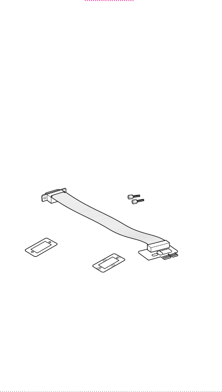
For this installation, you need the following parts: the video
connector assembly, two jacknuts, and two small metal
brackets. (One of the brackets has four ribs on it. The other
one is plain.)
You won’t need other parts in the package. They are for
installing the external video connector kit in other computer
models.
External video
connector assembly
Small metal bracket
Jack nuts
Small metal bracket with ribs
5
CHAPTER
2
Installing the Apple External
Video Connector in a
5400 Series Macintosh Computer

Opening the computer
1If your computer is on, choose Shut Down from the Special
menu, or press the Power key on the keyboard.
Keep your computer plugged in to a three-hole grounded
outlet to ground the computer and protect it from
electrical damage.
Important To avoid generating static electricity that may
damage components, do not walk around the room until
you have completed the installation of the connector and
closed the computer. Additionally, move the logic board as
little as possible while it is outside the computer.
2Turn the computer completely off by pressing the power
switch on the back of the computer.
Press the side of the switch marked with the jsymbol.
3Unplug the cable that connects your keyboard to the
computer.
6Chapter 2
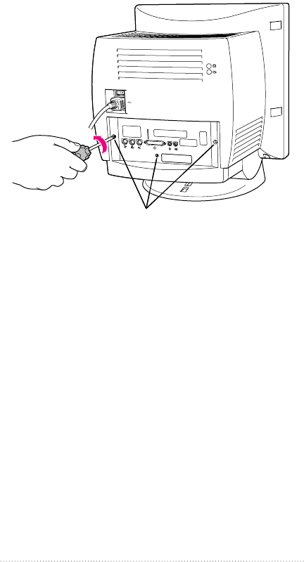
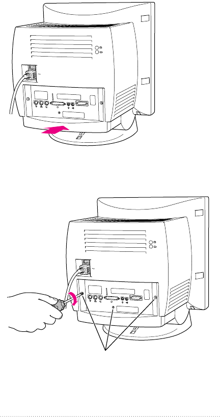
4Remove the security screws on the computer’s back panel
with a screwdriver.
Remove these screws.
(Your computer may have only two screws.)
7
Installing in a 5400 Series Macintosh Computer
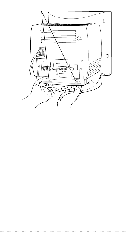
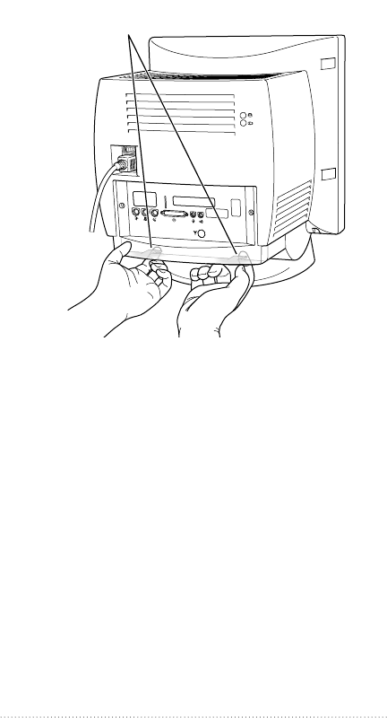
5With your fingertips, find the two latches on the underside
of the computer’s case.
6Pull gently on the latches.
Locate the two latches on the underside of the computer’s
case with your fingertips.
8Chapter 2
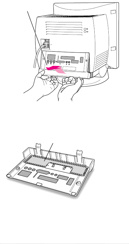
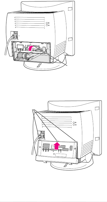
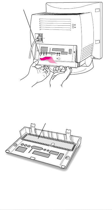
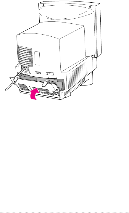
7Swing the panel up and slip it out.
8Carefully set the panel aside.
To protect the metal shielding on the inside of the panel, lay
down the panel so that the metal shielding faces up.
Metal shielding
Pulling gently, swing the
panel up, and slip it out.
9
Installing in a 5400 Series Macintosh Computer

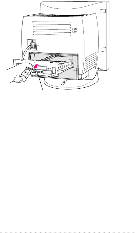
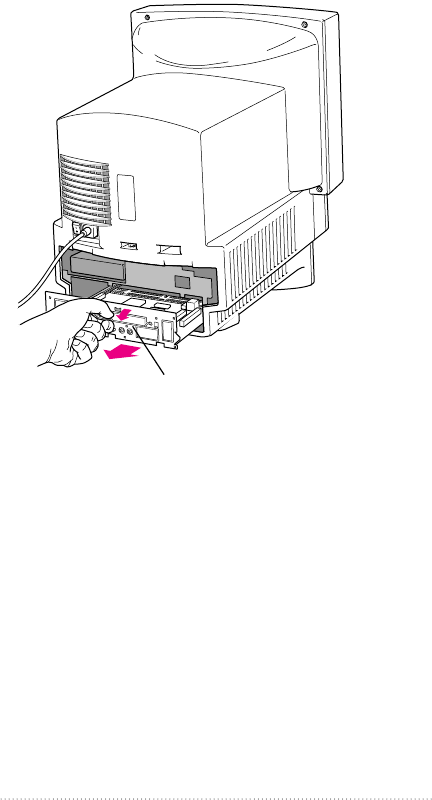
9Swing the wire handle out from its storage position. Then
grasp the handle and gently but firmly pull it toward you.
The vertical plate and the logic board to which it’s attached
slide all the way out of the computer.
10 Place the logic board on top of a magazine on a stable, clean,
flat surface.
The magazine will protect the bottom of the logic board and
prevent it from scratching your working surface.
Remember: Don’t walk around the room until you have
completed the installation of the connector and closed the
computer. Move the logic board as little as possible while it
is outside the computer.
Wire handle
10 Chapter 2
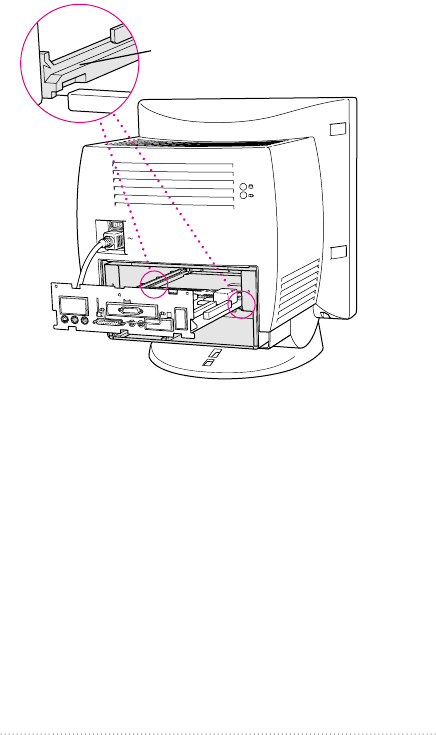
Removing the access cover
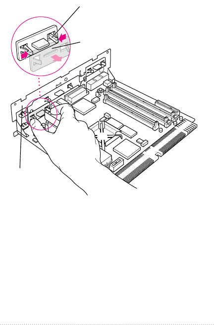
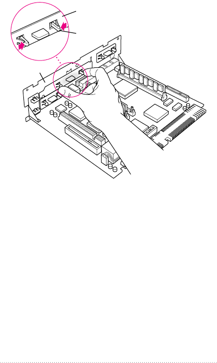
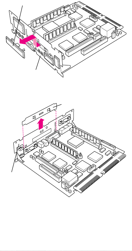
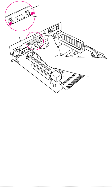
1Remove the small plastic access cover and the metal retainer
from the vertical plate.
Be sure to remove the correct access cover—the one shown
in the illustration below. Squeeze the two plastic tabs
together and pull the metal retainer so the access cover
comes off.
Squeeze the two plastic tabs together and
pull off the metal retainer so the access
cover can come off.
Vertical plate
Metal retainer
11
Installing in a 5400 Series Macintosh Computer
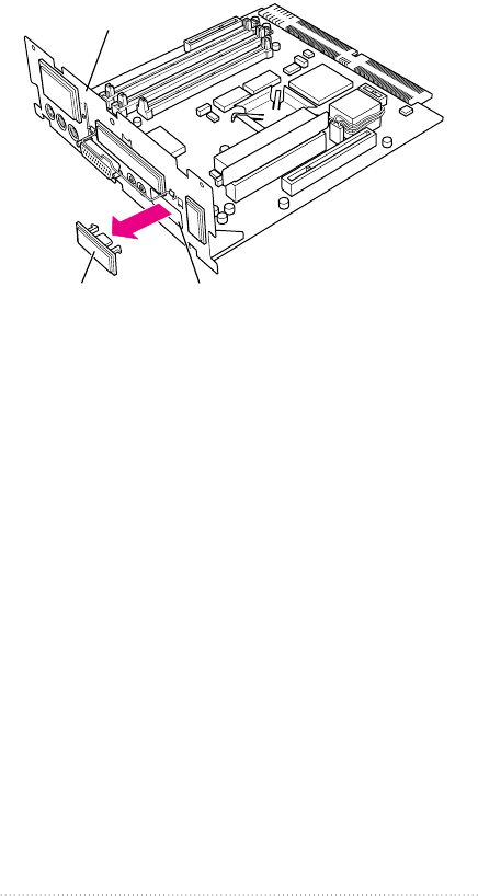
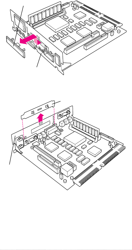
2Push the cover out. Set it aside.
Note Be sure to keep the plastic access cover and the
metal retainer; don’t throw them away. If you ever remove
the external video connector, you should replace the access
cover and the retainer on your computer.
Installing the external video connector
assembly
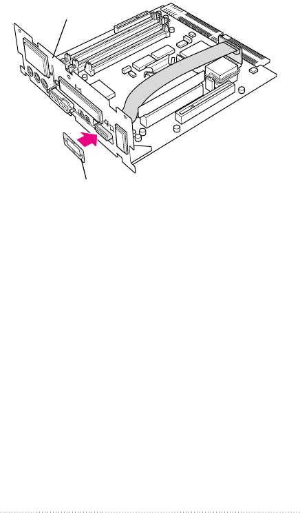
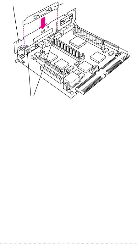
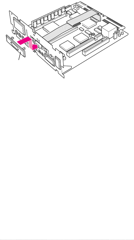
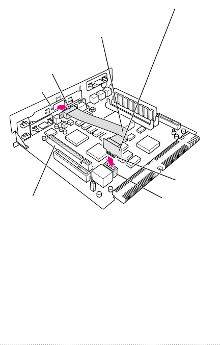
1Insert the small card at the end of the external video
connector assembly into the monitor-out slot on the logic
board. The card will fit in the slot only one way.
Vertical plate
Plastic access cover Opening in vertical plate
12 Chapter 2
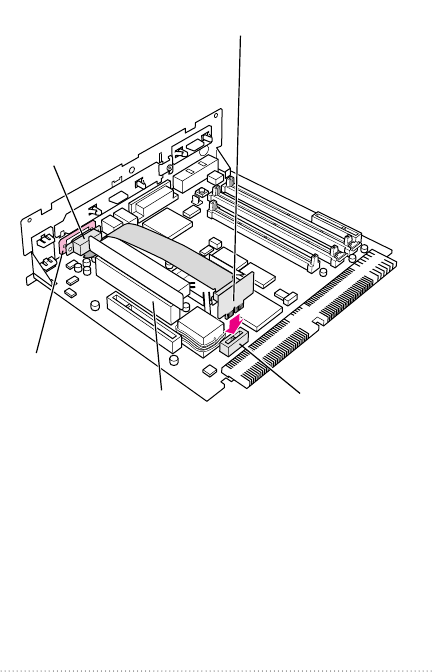
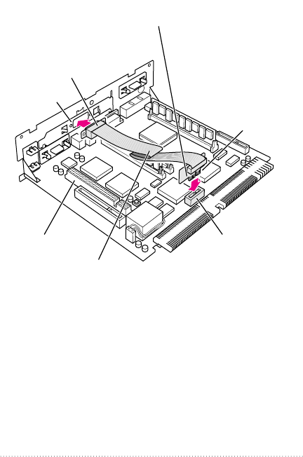
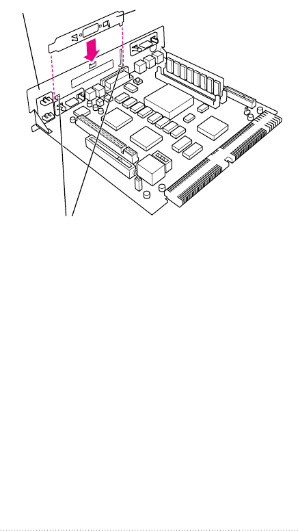
2Place the small metal bracket (the one without the ribs) over
the port on the other end of the video connector assembly.
Then insert the port through the opening on the vertical
plate.
If you already have an expansion card installed in the
computer’s PCI slot, lay the cable over (not under) the
expansion card.
Monitor-out slotPCI slot
1 Insert the small card into the monitor-out slot.
The card will fit in the slot only one way.
2 Insert the video connector
through the hole in the small
metal bracket, and pass the
video connector through
the opening in the
vertical plate.
Small metal
bracket (shown
tinted here)
13
Installing in a 5400 Series Macintosh Computer
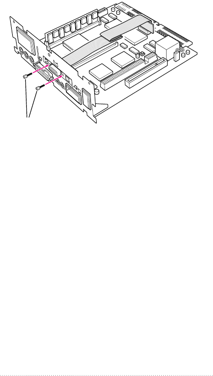
3Place the small metal bracket with ribs over the port on the
other side of the vertical plate.
Make sure the ribs face inward so that they help align the
port in the port opening.
Vertical plate
Small metal bracket with ribs
(The ribs should face the vertical plate.)
14 Chapter 2
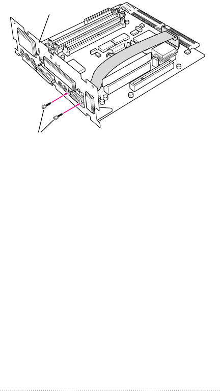
4Insert the jack nuts into the small holes on either side of the
video connector and tighten them.
This secures the connector to the vertical plate.
Vertical plate
Secure the video connector and the two small metal brackets
by installing the two jack nuts with your fingers. You can
tighten them with either a small wrench or nutdriver.
15
Installing in a 5400 Series Macintosh Computer
Closing the computer
1Slip the base of the logic board into the guide rails inside the
computer’s case.
Make sure the logic board slides
into the guides that are on both
sides of the computer’s interior.
16 Chapter 2
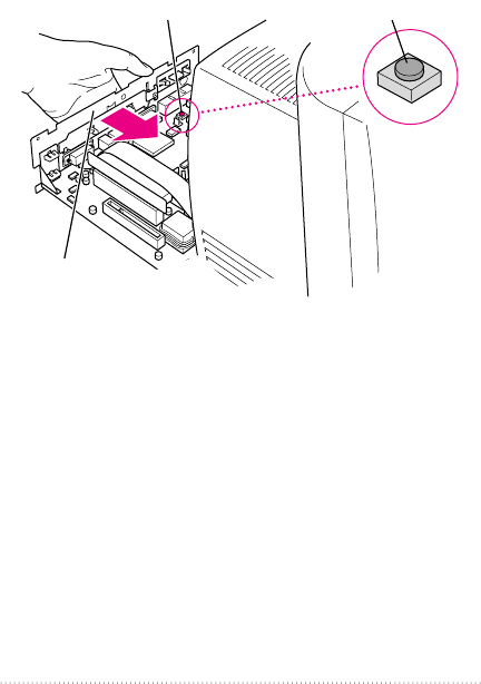
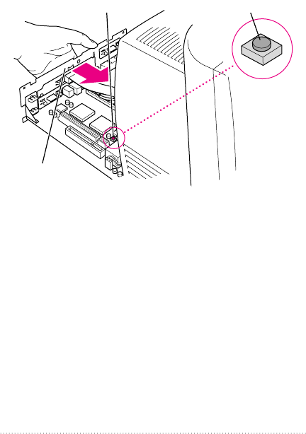
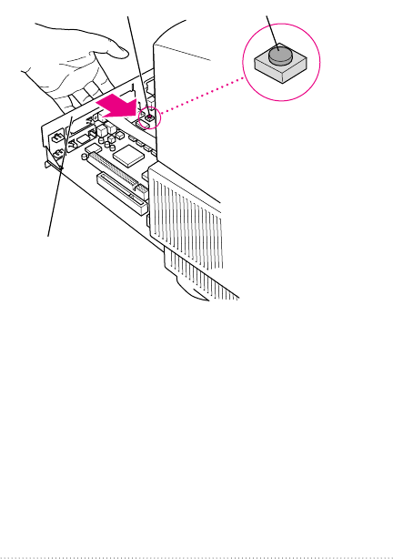
2Press the reset button on the logic board and then slide the
logic board back into the computer.
Note When you press the reset button, some of your
computer’s software settings will change. You may want to
open the control panels for the date and time, keyboard, and
mouse to make sure that they are set the way you want
them. For more information about working with control
panels, see Macintosh Guide, the on-screen help that’s
available in the Guide (h) menu.
1 Press the reset button.
2 Gently but
firmly push the
vertical plate until the logic
board is solidly back in place.
Reset button
17
Installing in a 5400 Series Macintosh Computer
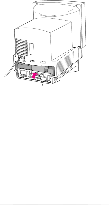
3Swing the wire handle back into its storage position.
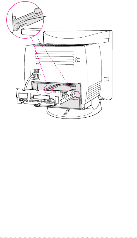
4Slip the three tabs at the top of the back panel into the
grooves in the computer’s case.
Slip the three tabs on the
back panel into the grooves
in the computer’s case.
Swing the handle up,
into its storage position.
18 Chapter 2
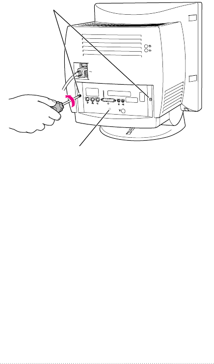
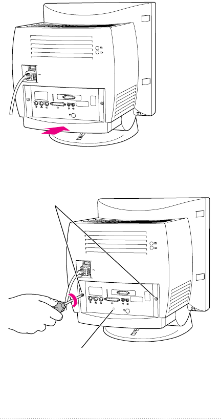
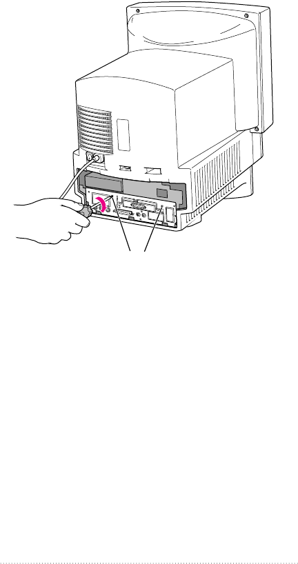
5Snap the base of the back panel into place.
6Reinsert the security screws.
Reinsert these screws.
Snap the plastic back panel into place.
19
Installing in a 5400 Series Macintosh Computer

7Reconnect the cables you disconnected at the beginning of
this process.
8Turn on the power switch on the back of the computer.
The external video connector is now installed.
Reminder: When you turn on your computer, don’t forget
to open the control panels for the date and time, keyboard,
and mouse to make sure that they are set the way you want
them. (Pressing the reset button on the logic board changed
these settings.) For more information about working with
control panels, see Macintosh Guide, the on-screen help
that’s available in the Guide (h) menu.
Connecting a second monitor or display
to the external video connector
By connecting a second monitor, a liquid crystal display
(LCD) panel, or the Apple Presentation System to the
external video connector, you can simultaneously display on
a second device the images shown on your computer screen.
The instructions below are specifically for connecting a
second monitor, but step one is basically the same for
connecting an LCD panel or the Apple Presentation System.
(For further information about connecting an LCD panel,
follow the instructions that came with the panel.)
20 Chapter 2
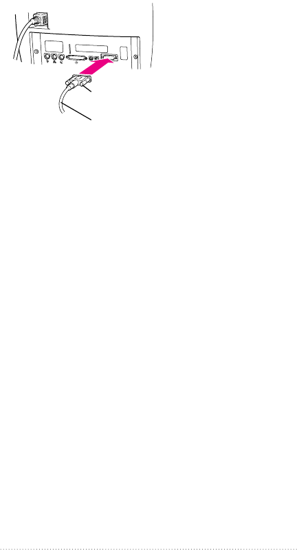
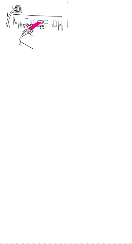
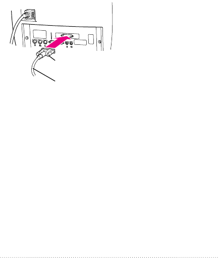
1Attach the second monitor’s monitor cable to the external
video connector and tighten the thumbscrews.
2Plug the monitor into a power source.
3Turn the monitor on.
On Apple monitors, the power switch is located on either
the front or the back of the monitor. See the manual that
came with the monitor.
The second monitor is ready to use.
You can turn your computer back on now.
Warning Never turn on your computer unless all of its
internal and external parts are in place. Operating the
computer when it is open or missing parts can be
dangerous, and can damage your computer.
Thumbscrews
Monitor cable from the second monitor
21
Installing in a 5400 Series Macintosh Computer

To install the external video connector kit in a 5200 series
or 5300 series Macintosh desktop computer, follow the
instructions in this chapter.
Opening the computer
1If your computer is on, choose Shut Down from the Special
menu, or press the Power key on the keyboard.
Keep your computer plugged into a three-hole grounded
outlet to ground the computer and protect it from
electrical damage.
Important To avoid generating static electricity that may
damage components, do not walk around the room until
you have completed the installation of the connector and
closed the computer. Additionally, move the logic board as
little as possible while it is outside the computer.
2Turn the computer completely off by pressing the power
switch at the back of the computer.
Press the side of the switch marked with the jsymbol.
23
CHAPTER
3
Installing the Apple External
Video Connector in a
5200 Series or 5300 Series
Macintosh Computer
3Unplug the cable that connects your keyboard to the
computer.
4Remove the security screws on either side of the computer’s
back panel with a screwdriver.
Remove both screws
Your computer may have a third screw here.
24 Chapter 3
5With your fingertips, find the two latches on the underside
of the computer’s case.
6Pull gently on the latches.
Locate the two latches on the underside of the computer’s
case with your fingertips.
25
Installing in a 5200 Series or 5300 Series Macintosh Computer
7Swing the panel up and slip it out. Set the panel aside.
8Carefully set the panel aside.
To protect the metal shielding on the inside of the panel, lay
down the panel so that the metal shielding faces up.
Metal shielding
Pulling gently, swing the
panel up, and slip it out.
26 Chapter 3
9Swing the wire handle out from its storage position. Then
grasp the handle and gently but firmly pull it toward you.
The vertical plate and the logic board to which it’s attached
slide all the way out of the computer.
10 Place the logic board on top of a magazine on a stable, clean,
flat surface.
The magazine will protect the bottom of the logic board and
prevent it from scratching your working surface.
Remember: Don’t walk around the room until you have
completed the installation of the connector and closed the
computer. Move the logic board as little as possible while it
is outside the computer.
Wire handle
27
Installing in a 5200 Series or 5300 Series Macintosh Computer
Installing the metal bracket
1Remove the plastic access cover from the vertical plate.
Squeeze the two plastic tabs together and pull the metal
retainer so the access cover comes off.
Vertical plate
Plastic tabs
Metal retainer
28 Chapter 3
2Push the cover out. Set it aside.
3Lift the metal retainer up and out. Set it aside.
Vertical plate
Metal retainer
Vertical plate
Plastic access cover
29
Installing in a 5200 Series or 5300 Series Macintosh Computer
4Insert the metal bracket that came with your external video
connector kit. Make sure the bottom of the bracket engages
the two small hooks on the logic board’s vertical plate.
Vertical plate
The metal bracket is properly
seated when it engages these two hooks.
Metal bracket
30 Chapter 3
Installing the external video connector
assembly
1Insert the small card at the end of the external video
connector assembly into the monitor-out slot on the logic
board. The card will fit in the slot only one way.
2Insert the video connector at the end of the ribbon cable
through the opening in the metal bracket.
3If there is slack in the cable, fold it as shown.
If you already have an expansion card installed in the
computer’s processor-direct slot, lay the cable over (not
under) the expansion card.
Monitor-out slot
Connectors
3 Remove any slack in the
cable by folding the cable as shown.
1 Insert the small card into the monitor-out slot.
The card will fit in the slot only one way.
2 Insert the video connector
through the hole in the
metal bracket.
Metal bracket
Processor-direct slot
31
Installing in a 5200 Series or 5300 Series Macintosh Computer
4Insert the jack nuts into the small holes on either side of the
video connector and tighten them.
This secures the connector to the vertical plate.
Secure the video connector
by installing the two jack nuts with
your fingers. You can tighten them with
either a small wrench or nutdriver.
32 Chapter 3
5Snap the plastic access cover onto the vertical plate. Make
sure the connector protrudes through the opening in
the cover.
Snap on the
plastic access cover.
33
Installing in a 5200 Series or 5300 Series Macintosh Computer
Closing the computer
1Slip the base of the logic board into the guide rails inside the
computer’s case, and swing the wire handle back into its
storage position.
Make sure the logic board slides
into the guides that are on both
sides of the computer’s interior.
34 Chapter 3
2Press the reset button on the logic board and then slide the
logic board back into the computer.
Note When you press the reset button, some of your
computer’s software settings will change. You may want to
open the control panels for the date and time, keyboard, and
mouse to make sure that they are set the way you want
them. For more information about working with control
panels, see Macintosh Guide, the on-screen help that’s
available in the Guide (h) menu.
1 Press the reset button.
2 Gently but
firmly push the
vertical plate until the logic
board is solidly back in place.
Reset button
35
Installing in a 5200 Series or 5300 Series Macintosh Computer

3Swing the wire handle back into its storage position.
4Slip the three tabs at the top of the back panel into the
grooves in the computer’s case.
Slip the three tabs on the
back panel into the grooves
in the computer’s case.
Swing the handle up,
into its storage position.
36 Chapter 3
5Snap the base of the back panel into place.
6Reinsert the security screws.
Reinsert both screws
Your computer may have a third screw
here which you will need to reinsert.
Snap the plastic back panel into place.
37
Installing in a 5200 Series or 5300 Series Macintosh Computer

7Reconnect the cables you disconnected at the beginning of
this process.
The external video connector is now installed.
Reminder: When you turn on your computer, don’t forget
to open the control panels for the date and time, keyboard,
and mouse to make sure that they are set the way you want
them. (Pressing the reset button on the logic board changed
these settings.) For more information about working with
control panels, see Macintosh Guide, the on-screen help
that’s available in the Guide (h) menu.
Connecting a second monitor or display
to the external video connector
By connecting a second monitor, a liquid crystal display
(LCD) panel, or the Apple Presentation System to the
external video connector, you can simultaneously display on
a second device the images shown on your computer screen.
The instructions below are specifically for connecting a
second monitor, but step one is basically the same for
connecting an LCD panel or the Apple Presentation System.
(For further information about connecting an LCD panel,
follow the instructions that came with the panel.)
38 Chapter 3
1Attach the second monitor’s monitor cable to the external
video connector and tighten the thumbscrews.
2Plug the monitor into a power source.
3Turn the monitor on.
On Apple monitors, the power switch is located on either
the front or the back of the monitor. See the manual that
came with the monitor.
The second monitor is ready to use.
You can turn your computer back on now.
Warning Never turn on your computer unless all of its
internal and external parts are in place. Operating the
computer when it is open or missing parts can be
dangerous, and can damage your computer.
Thumbscrews
Monitor cable from the second monitor
39
Installing in a 5200 Series or 5300 Series Macintosh Computer

To install the external video connector kit in a 580 series
Macintosh computer, follow the instructions in this chapter.
Opening the computer
1If your computer is on, choose Shut Down from the Special
menu, or press the Power key on the keyboard.
Keep your computer plugged into a three-hole grounded
outlet to ground the computer and protect it from
electrical damage.
Important To avoid generating static electricity that may
damage components, do not walk around the room until
you have completed the installation of the connector and
closed the computer. Additionally, move the logic board as
little as possible while it is outside the computer.
2Turn the computer completely off by pressing the power
switch at the back of the computer.
Press the side of the switch marked with the jsymbol.
41
CHAPTER
4
Installing the Apple External
Video Connector in a
580 Series Macintosh Computer
3Unplug the cable that connects your keyboard to
the computer.
4If there are security screws on either side of the computer’s
back panel, remove them with a screwdriver.
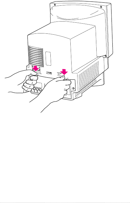
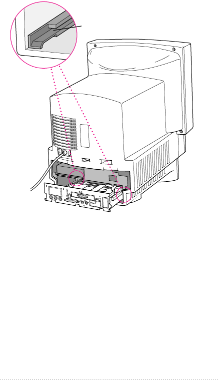
5Place your thumbs on the two plastic tabs on the back panel
of the computer.
42 Chapter 4
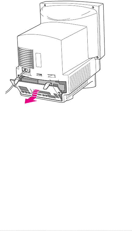
6Press down on the tabs and pull gently until the back panel
opens.
7Take the back panel off and set it aside.
43
Installing in a 580 Series Macintosh Computer
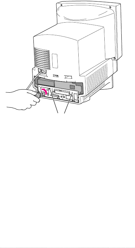
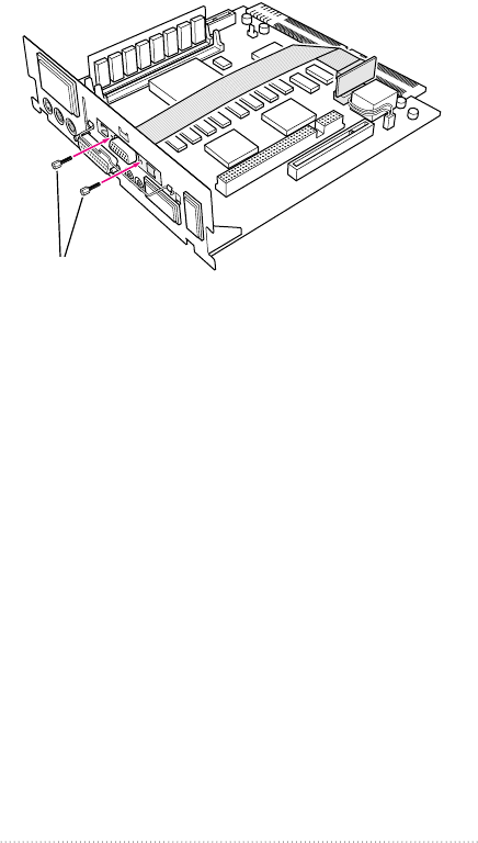
8Remove both retainer screws from the vertical plate with
a screwdriver.
Remove both retainer screws from the vertical plate.
44 Chapter 4
9Swing the wire handle down from the vertical plate and
gently pull the logic board out of the computer.
10 Place the logic board on top of a magazine on a stable, clean,
flat surface.
The magazine will protect the bottom of the logic board and
prevent it from scratching your working surface.
Remember: Don’t walk around the room until you have
completed the installation of the connector and closed the
computer. Move the logic board as little as possible while it
is outside the computer.
Wire handle
45
Installing in a 580 Series Macintosh Computer
Installing the metal bracket
1Remove the plastic access cover from the vertical plate.
Squeeze the two plastic tabs together and pull the metal
retainer so the access cover comes off.
Vertical plate
Plastic tabs
Metal retainer
46 Chapter 4
2Push the cover out. Set it aside.
3Lift the metal retainer up and out. Set it aside.
Vertical plate
Metal retainer
Vertical plate
Plastic access cover
47
Installing in a 580 Series Macintosh Computer
4Insert the metal bracket that came with your external video
connector kit. Make sure the bottom of the bracket engages
the two small hooks on the logic board’s vertical plate.
Vertical plate
The metal bracket is properly
seated when it engages these two hooks.
Metal bracket
48 Chapter 4
Installing the external video connector
assembly
1Insert the small card into the monitor-out slot on the logic
board. The card will fit in the slot only one way.
2Insert the video connector at the end of the ribbon cable
through the opening in the metal bracket.
If you already have an expansion card installed in the
computer’s processor-direct slot, lay the cable over (not
under) the expansion card.
Monitor-out slot
Connectors
3 Insert the video connector
through the hole in the
metal bracket.
1 Insert the small card into the monitor-out slot. The card will fit
in the slot only one way.
2 Fold the ribbon cable as shown.
Metal bracket
Processor-direct slot
49
Installing in a 580 Series Macintosh Computer
3Insert the jack nuts into the small holes on either side of the
video connector and tighten them.
This secures the connector to the vertical plate.
Secure the video connector
by installing the two jack nuts with
your fingers. You can tighten them with
either a small wrench or nutdriver.
50 Chapter 4
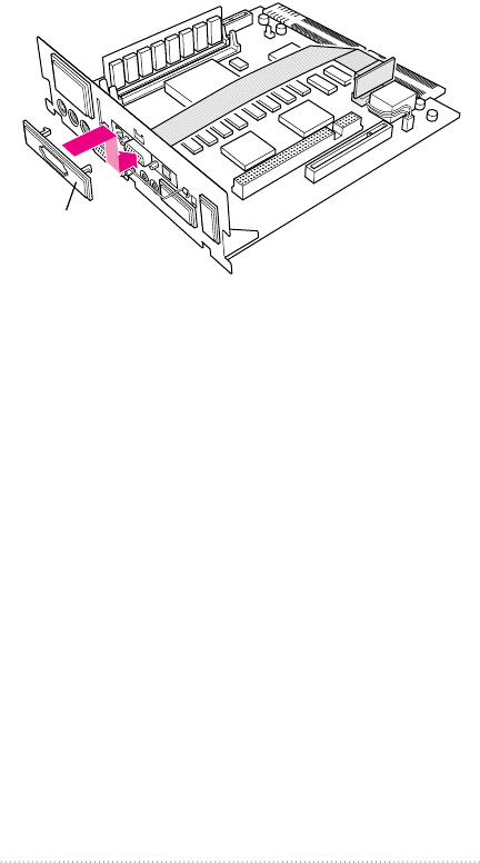
4Snap the plastic access cover onto the vertical plate. Make
sure the connector protrudes through the opening in
the cover.
Snap on the
plastic access cover.
51
Installing in a 580 Series Macintosh Computer
Closing the computer
1Slip the base of the logic board into the guide rails inside the
computer’s case.
Make sure the logic board slides
into the guides that are on both
sides of the computer’s interior.
52 Chapter 4
2Press the reset button on the logic board and then slide the
logic board back into the computer.
Note When you press the reset button, some of your
computer’s software settings will change. You may want to
open the control panels for the date and time, keyboard, and
mouse to make sure that they are set the way you want
them. For more information about working with control
panels, see Macintosh Guide, the on-screen help that’s
available in the Guide (h) menu.
1 Press the reset button.
2 Gently but firmly
push on the vertical plate
until the logic board is
solidly back in place.
Reset button
53
Installing in a 580 Series Macintosh Computer
3Swing the wire handle back into its storage position.
Swing the handle up, into its storage position.
54 Chapter 4
4Reinsert the retainer screws into the vertical plate.
Reinsert both retainer screws into the vertical plate.
55
Installing in a 580 Series Macintosh Computer
5Replace the back panel of the computer.
Slip the back panel over the prongs at the bottom edge of
the back of the computer, then push the back panel up and
forward until it snaps into place. If the back panel was held
on by security screws, reinsert them.
6Reconnect the cables you disconnected at the beginning of
this process.
The external video connector is now installed.
Reminder: When you turn on your computer, don’t forget
to open the control panels for the date and time, keyboard,
and mouse to make sure that they are set the way you want
them. (Pressing the reset button on the logic board changed
these settings.) For more information about working with
control panels, see Macintosh Guide, the on-screen help
that’s available in the Guide (h) menu.
56 Chapter 4
Connecting a second monitor or display
to the external video connector
By connecting a second monitor, a liquid crystal display
(LCD) panel, or the Apple Presentation System to the
external video connector, you can simultaneously display on
a second device the images displayed on your computer
screen. The instructions below are specifically for connecting
a second monitor, but step one is basically the same for
connecting an LCD panel or the Apple Presentation System.
(For further information about connecting an LCD panel,
follow the instructions that came with the panel.)
1Attach the second monitor’s monitor cable to the external
video connector and tighten the thumbscrews.
2Plug the monitor into a power source.
Thumbscrews
Monitor cable from the second monitor
57
Installing in a 580 Series Macintosh Computer

3Turn the monitor on.
On Apple monitors, the power switch is located on either
the front or the back of the monitor. See the manual that
came with the monitor.
The second monitor is ready to use.
You can turn your computer back on now.
Warning Never turn on your computer unless all of its
internal and external parts are in place. Operating the
computer when it is open or missing parts can be
dangerous, and can damage your computer.
58 Chapter 4

Apple
External Video
Connector
Installation Manual
KApple Computer, Inc.
©1996 Apple Computer, Inc. All rights reserved.
Under the copyright laws, this manual may not be copied, in whole or part, without
the written consent of Apple. Your rights to the software are governed by the
accompanying software license agreement.
The Apple logo is a trademark of Apple Computer, Inc., registered in the U.S. and
other countries. Use of the “keyboard” Apple logo (Option-Shift-K) for commercial
purposes without the prior written consent of Apple may constitute trademark
infringement and unfair competition in violation of federal and state laws.
Every effort has been made to ensure that the information in this manual is accurate.
Apple is not responsible for printing or clerical errors.
Apple Computer, Inc.
1 Infinite Loop
Cupertino, CA 95014-2084
(408) 996-1010
Apple, the Apple logo, LaserWriter, Macintosh and Power Macintosh are trademarks of
Apple Computer, Inc., registered in the U.S. and other countries.
Adobe, Adobe Illustrator, Adobe Photoshop, and PostScript are trademarks of Adobe
Systems Incorporated or its subsidiaries and may be registered in certain jurisdictions.
Helvetica is a registered trademark of Linotype-Hell AG and/or its subsidiaries.
. Simultaneously published in the United States and Canada.
Mention of third-party products is for informational purposes only and constitutes
neither an endorsement nor a recommendation. Apple assumes no responsibility with
regard to the performance or use of these products.
The Apple Publishing System
This Apple manual was written, edited, and produced on a desktop publishing system
using Apple Macintosh computers and QuarkXPress. Technical illustrations were
drawn in Adobe™Illustrator; screen shots were created and modified with system
software, ExposurePro, and Adobe Photoshop. Final pages were output using
PostScript™technology.
Text type is Apple Garamond, Apple’s corporate font. Display type is Helvetica®Black.
Ornaments are custom symbols designed for Apple Computer.
PostScript, the LaserWriter page-description language, was developed by Adobe
Systems Incorporated.

CONTENTS
Communications regulation information iv
1 Getting Started 1
Do you have what you need? 2
2 Installing the Apple External Video Connector
in a 5400 Series Macintosh Computer 5
Opening the computer 6
Removing the access cover 11
Installing the external video connector assembly 12
Closing the computer 16
Connecting a second monitor or display to the external video
connector 20
3 Installing the Apple External Video Connector
in a 5200 Series or 5300 Series Macintosh
Computer 23
Opening the computer 23
Installing the metal bracket 28
Installing the external video connector assembly 31
Closing the computer 34
Connecting a second monitor or display to the external video
connector 38
4 Installing the Apple External Video Connector
in a 580 Series Macintosh Computer 41
Opening the computer 41
Installing the metal bracket 46
Installing the external video connector assembly 49
Closing the computer 52
Connecting a second monitor or display to the external video
connector 57
iii

Communications regulation information
FCC statement
This equipment has been tested and found to comply with the limits for a Class B
digital device in accordance with the specifications in Part 15 of FCC rules. See
instructions if interference to radio or television reception is suspected.
Radio and television interference
The equipment described in this manual generates, uses, and can radiate radio-
frequency energy. If it is not installed and used properly—that is, in strict accordance
with Apple’s instructions—it may cause interference with radio and television
reception.
This equipment has been tested and found to comply with the limits for a Class B
digital device in accordance with the specifications in Part 15 of FCC rules. These
specifications are designed to provide reasonable protection against such interference
in a residential installation. However, there is no guarantee that interference will not
occur in a particular installation.
You can determine whether your computer system is causing interference by turning it
off. If the interference stops, it was probably caused by the computer or one of the
peripheral devices.
If your computer system does cause interference to radio or television reception, try to
correct the interference by using one or more of the following measures:
mTurn the television or radio antenna until the interference stops.
mMove the computer to one side or the other of the television or radio.
mMove the computer farther away from the television or radio.
mPlug the computer into an outlet that is on a different circuit from the television or
radio. (That is, make certain the computer and the television or radio are on circuits
controlled by different circuit breakers or fuses.)
If necessary, consult an Apple-authorized service provider or Apple. See the service
and support information that came with your Apple product. Or, consult an
experienced radio/television technician for additional suggestions.
Important Changes or modifications to this product not authorized by Apple
Computer, Inc., could void the FCC Certification and negate your authority to operate
the product.
iv
This product was tested for FCC compliance under conditions that included the use of
Apple peripheral devices and Apple shielded cables and connectors between system
components. It is important that you use Apple peripheral devices and shielded cables
and connectors between system components to reduce the possibility of causing
interference to radios, television sets, and other electronic devices. You can obtain
Apple peripheral devices and the proper shielded cables and connectors through an
Apple-authorized dealer. For non-Apple peripheral devices, contact the manufacturer
or dealer for assistance.
DOC statement
DOC Class B Compliance This digital apparatus does not exceed the Class B limits for
radio noise emissions from digital apparatus as set out in the interference-causing
equipment standard entitled “Digital Apparatus,” ICES-003 of the Department of
Communications.
Observation des normes—Classe B Cet appareil numérique respecte les limites de
bruits radioélectriques applicables aux appareils numériques de Classe B prescrites
dans la norme sur le matériel brouilleur : “Appareils Numériques”, NMB-003 édictée
par le ministre des Communications.
VCCI statement
v
