Apple Logic Pro X Effects User Manual
Logic Pro - X - Effects logic_pro_x_effects Free User Guide for Apple Logic Software, Manual
2013-07-16
User Manual: Apple Logic Pro X Logic Pro X Effects
Open the PDF directly: View PDF ![]() .
.
Page Count: 286 [warning: Documents this large are best viewed by clicking the View PDF Link!]
- Logic Pro X Effects
- Contents
- Chapter 1: Amps and pedals
- Chapter 2: Delay effects
- Chapter 3: Distortion effects
- Chapter 4: Dynamics processors
- Chapter 5: Equalizers
- Chapter 6: Filter effects
- Filter effects overview
- AutoFilter
- EVOC 20 Filterbank
- EVOC 20 TrackOscillator
- EVOC 20 TrackOscillator overview
- Vocoder overview
- EVOC 20 TrackOscillator interface
- EVOC 20 TrackOscillator analysis in parameters
- Use EVOC 20 TrackOscillator analysis in
- EVOC 20 TrackOscillator U/V detection parameters
- EVOC 20 TrackOscillator synthesis in parameters
- EVOC 20 TrackOscillator oscillators
- EVOC 20 TrackOscillator formant filter
- EVOC 20 TrackOscillator modulation
- EVOC 20 TrackOscillator output parameters
- Fuzz-Wah
- Spectral Gate
- Chapter 7: Imaging processors
- Chapter 8: Metering tools
- Chapter 9: MIDI plug-ins
- Chapter 10: Modulation effects
- Chapter 11: Pitch effects
- Chapter 12: Reverb effects
- Chapter 13: Space Designer convolution reverb
- Chapter 14: Specialized effects and utilities
- Chapter 15: Utilities and tools
- Appendix: Legacy effects

Logic Pro X Eects
For OS X
100
KApple Inc.
Copyright © 2013 Apple Inc. All rights reserved.
Your rights to the software are governed by the accompanying
software license agreement. The owner or authorized user
of a valid copy of Logic Pro software may reproduce this
publication for the purpose of learning to use such software.
No part of this publication may be reproduced or transmitted
for commercial purposes, such as selling copies of this
publication or for providing paid for support services.
The Apple logo is a trademark of Apple Inc., registered in
the U.S. and other countries. Use of the “keyboard” Apple
logo (Shift-Option-K) for commercial purposes without the
prior written consent of Apple may constitute trademark
infringement and unfair competition in violation of federal and
state laws.
Every eort has been made to ensure that the information in
this manual is accurate. Apple is not responsible for printing or
clerical errors.
Because Apple frequently releases new versions and updates
to its system software, applications, and Internet sites, images
shown in this manual may be slightly dierent from what you
see on your screen.
Apple
1 Innite Loop
Cupertino, CA 95014
408-996-1010
www.apple.com
Apple, the Apple logo, Final Cut Pro, Finder, FireWire,
GarageBand, iMovie, iPad, iPhoto, iPod, iSight, iTunes,
iTunes Store, Jam Pack, Logic, Logic Pro, Mac, Macintosh,
MainStage, QuickTime, and Ultrabeat are trademarks of Apple
Inc., registered in the U.S. and other countries.
IOS is a trademark or registered trademark of Cisco in the U.S.
and other countries and is used under license.
Other company and product names mentioned herein
are trademarks of their respective companies. Mention of
third-party products is for informational purposes only and
constitutes neither an endorsement nor a recommendation.
Apple assumes no responsibility with regard to the
performance or use of these products.
019-2553
Contents
10 Chapter 1: Amps and pedals
10 Amps and pedals overview
10 Amp Designer
10 Amp Designer overview
13 Amp Designer models
18 Build a custom Amp Designer combo
21 Amp Designer equalizer
23 Amp Designer amplier controls
24 Amp Designer eects
26 Amp Designer microphone parameters
27 Bass Amp Designer
27 Bass Amp Designer overview
28 Bass Amp Designer models
29 Build a custom Bass Amp Designer combo
30 Bass Amp Designer signal ow
32 Use the D.I. box
33 Bass Amp Designer amplier controls
34 Bass Amp Designer eects
37 Bass Amp Designer microphone parameters
38 Pedalboard
38 Pedalboard overview
39 Use the Pedal Browser
40 Use Pedalboard’s import mode
41 Use the Pedal area
42 Use Pedalboard’s Router
44 Use Pedalboard’s Macro Controls
45 Pedalboard distortion pedals
46 Pedalboard modulation pedals
50 Pedalboard delay pedals
51 Pedalboard lter pedals
51 Pedalboard dynamics pedals
52 Pedalboard utility pedals
3
53 Chapter 2: Delay eects
53 Delay eects overview
54 Delay Designer
54 Delay Designer overview
55 Delay Designer main display
56 Use the Delay Designer Tap display
59 Create taps in Delay Designer
61 Select, move, and delete taps
63 Edit parameters in the Tap display
68 Delay Designer Tap parameter bar
69 Delay Designer sync mode
70 Delay Designer master parameters
71 Use Delay Designer in surround
72 Echo
72 Sample Delay
73 Stereo Delay
74 Tape Delay
76 Chapter 3: Distortion eects
76 Distortion eects overview
77 Bitcrusher
78 Clip Distortion
79 Distortion eect
79 Distortion II
80 Overdrive
81 Phase Distortion
82 Chapter 4: Dynamics processors
82 Dynamics processors overview
83 Adaptive Limiter
84 Compressor
84 Compressor overview
86 Use Compressor
87 DeEsser
89 Use Ducker
90 Enveloper
92 Expander
93 Limiter
94 Multipressor
94 Multipressor overview
94 Multipressor Display parameters
95 Multipressor Frequency Band parameters
96 Multipressor Output parameters
97 Use Multipressor
98 Noise Gate
98 Noise Gate overview
99 Use Noise Gate
Contents 4
100 Surround Compressor
100 Surround Compressor overview
101 Surround Compressor Link parameters
102 Surround Compressor Main parameters
103 Surround Compressor LFE parameters
104 Chapter 5: Equalizers
104 Equalizers overview
104 Channel EQ
104 Channel EQ overview
105 Channel EQ parameters
106 Channel EQ use tips
107 Channel EQ Analyzer
107 Linear Phase EQ
107 Linear Phase EQ overview
108 Linear Phase EQ parameters
109 Linear Phase EQ use tips
110 Linear Phase EQ Analyzer
110 Match EQ
110 Match EQ overview
111 Match EQ parameters
113 Use Match EQ
115 Edit the Match EQ lter curve
116 Single-Band EQ
117 Chapter 6: Filter eects
117 Filter eects overview
117 AutoFilter
117 AutoFilter overview
118 AutoFilter threshold
118 AutoFilter envelope
119 AutoFilter LFO
120 AutoFilter lter
121 AutoFilter distortion
121 AutoFilter output
12 2 EVOC 20 Filterbank
12 2 EVOC 20 Filterbank overview
12 3 EVOC 20 Filterbank Formant Filter
124 EVOC 20 Filterbank modulation
125 EVOC 20 Filterbank output parameters
12 6 EVOC 20 TrackOscillator
12 6 EVOC 20 TrackOscillator overview
12 6 Vocoder overview
12 7 EVOC 20 TrackOscillator interface
128 EVOC 20 TrackOscillator analysis in parameters
128 Use EVOC 20 TrackOscillator analysis in
129 EVOC 20 TrackOscillator U/V detection parameters
131 EVOC 20 TrackOscillator synthesis in parameters
131 EVOC 20 TrackOscillator oscillators
133 EVOC 20 TrackOscillator formant lter
Contents 5
134 EVOC 20 TrackOscillator modulation
135 EVOC 20 TrackOscillator output parameters
13 6 Fuzz-Wah
13 6 Fuzz-Wah overview
13 6 Auto Wah parameters
13 8 Fuzz-Wah Compressor parameters
13 8 Fuzz parameters
13 9 Spectral Gate
13 9 Spectral Gate overview
140 Use Spectral Gate
141 Chapter 7: Imaging processors
141 Imaging processors overview
141 Binaural Post-Processing
142 Direction Mixer
142 Direction Mixer overview
143 Stereo miking techniques
145 Stereo Spread
146 Chapter 8: Metering tools
146 Metering tools overview
146 BPM Counter
147 Correlation Meter
147 Level Meter plug-in
148 MultiMeter
148 MultiMeter overview
149 MultiMeter Analyzer parameters
150 MultiMeter Goniometer parameters
151 MultiMeter Level Meter
151 MultiMeter Correlation Meter
152 MultiMeter Peak parameters
153 Surround MultiMeter
153 Surround MultiMeter overview
153 Surround MultiMeter Analyzer mode
154 Surround MultiMeter Goniometer mode
155 Surround MultiMeter Level Meter
156 Surround MultiMeter Balance/Correlation
157 Surround MultiMeter Peak parameters
158 Use the Tuner utility
Contents 6
159 Chapter 9: MIDI plug-ins
159 Use MIDI plug-ins
160 Arpeggiator MIDI plug-in
160 Arpeggiator overview
161 Arpeggiator control parameters
162 Arpeggiator note order parameters
167 Arpeggiator pattern parameters
170 Arpeggiator options parameters
171 Arpeggiator keyboard parameters
172 Use Arpeggiator keyboard parameters
173 Assign Arpeggiator controller parameters
174 Chord Trigger MIDI plug-in
174 Chord Trigger overview
175 Use Chord Trigger
178 Modier MIDI plug-in
179 Modulator MIDI plug-in
179 Modulator MIDI plug-in overview
179 Modulator MIDI plug-in LFO
181 Modulator MIDI plug-in envelope
183 Note Repeater MIDI plug-in
184 Randomizer MIDI plug-in
185 Scripter plug-in
185 Use the Scripter plug-in
186 Use the Script Editor
187 Scripter API overview
187 MIDI processing functions
190 JavaScript objects
193 Create Scripter controls
195 Transposer MIDI plug-in
196 Velocity Processor MIDI plug-in
196 Velocity Processor overview
197 Velocity Processor Compress/Expand mode
198 Velocity Processor Value/Range mode
198 Velocity Processor Add/Scale mode
199 Chapter 10: Modulation eects
199 Modulation eects overview
200 Chorus eect
201 Ensemble eect
202 Flanger eect
202 Microphaser
203 Modulation Delay
205 Phaser eect
206 Ringshifter
206 Ringshifter overview
206 Ringshifter interface
207 Set the Ringshifter mode
208 Ringshifter oscillator parameters
209 Ringshifter delay parameters
209 Ringshifter modulation
211 Ringshifter output parameters
Contents 7
212 Rotor Cabinet eect
212 Rotor Cabinet eect overview
213 Rotor Cabinet eect motor parameters
214 Rotor Cabinet eect microphone types
215 Rotor Cabinet eect mic processing controls
216 Scanner Vibrato eect
217 Spreader
218 Tremolo eect
219 Chapter 11: Pitch eects
219 Pitch eects overview
219 Pitch Correction eect
219 Pitch Correction eect overview
220 Pitch Correction eect parameters
221 Pitch Correction eect quantization grid
222 Exclude notes from pitch correction
223 Use Pitch Correction eect reference tuning
224 Pitch Shifter
224 Pitch Shifter overview
225 Use Pitch Shifter
226 Vocal Transformer
226 Vocal Transformer overview
226 Vocal Transformer parameters
227 Use Vocal Transformer
229 Chapter 12: Reverb eects
229 Reverb eects overview
230 EnVerb
230 EnVerb overview
231 EnVerb time parameters
232 EnVerb sound parameters
233 PlatinumVerb
233 PlatinumVerb overview
234 PlatinumVerb early reections parameters
235 PlatinumVerb reverb parameters
236 PlatinumVerb output parameters
237 SilverVerb
238 Chapter 13: Space Designer convolution reverb
238 Space Designer overview
239 Space Designer interface
240 Use impulse responses
243 Space Designer envelopes and EQ
243 Space Designer envelopes and EQ overview
244 Space Designer button bar
245 Edit Space Designer envelope parameters
246 Space Designer volume envelope
247 Space Designer density envelope
248 Use Space Designer EQ parameters
250 Space Designer lter
250 Space Designer lter parameters
251 Space Designer lter envelope
Contents 8
252 Space Designer global parameters
252 Space Designer global parameters overview
253 Use Space Designer global parameters
256 Use Space Designer output parameters
259 Chapter 14: Specialized eects and utilities
259 Specialized eects overview
259 Denoiser
259 Denoiser overview
260 Denoiser smoothing parameters
261 Exciter
262 Grooveshifter
263 Speech Enhancer
264 SubBass
264 SubBass overview
264 SubBass parameters
265 SubBass use tips
266 Chapter 15: Utilities and tools
266 Utilities and tools overview
266 Down Mixer
267 Gain plug-in
268 Use I/O utility
269 Multichannel Gain
270 Test Oscillator
271 Appendix: Legacy eects
271 Legacy eects overview
271 AVerb
272 Bass Amp
273 EQ
273 DJ EQ
274 Fat EQ
275 Single-Band EQs
276 Silver EQ
277 GoldVerb
277 GoldVerb overview
278 GoldVerb early reections parameters
279 GoldVerb reverb parameters
280 Guitar Amp Pro
280 Guitar Amp Pro overview
281 Guitar Amp Pro amplier models
281 Guitar Amp Pro cabinet models
282 Guitar Amp Pro EQ
282 Guitar Amp Pro amplier controls
283 Guitar Amp Pro eects
284 Guitar Amp Pro microphone parameters
285 Silver Compressor
286 Silver Gate
Contents 9
10
Amps and pedals overview
Logic Pro X features an extensive collection of guitar and bass ampliers and classic pedal eects.
You can play live—or process recorded audio and software instrument parts—through these
amps and eects.
The amplier models recreate vintage and modern tube and solid-state amps. Built-in eect
units, such as reverb, tremolo, or vibrato, are also reproduced. The modeled ampliers can be
paired with a number of emulated speaker cabinets. These ampliers and speaker cabinets can
be used as a matching set or combined in other ways to create interesting hybrids.
Also emulated are a number of “classic” foot pedal eects—or stompboxes—that were, and
remain, popular with guitarists and keyboardists. As with their real-world counterparts, you can
chain pedals in any order to create your sound.
Amp Designer
Amp Designer overview
Amp Designer emulates the sound of more than 20 famous guitar ampliers and the speaker
cabinets used with them. Each precongured model combines an amp, a cabinet, and EQ
that recreates a well-known guitar amplier sound. You can process guitar signals directly,
reproducing the sound of your guitar played through these amplication systems. You can also
use Amp Designer for experimental sound design and processing. You can use it with other
instruments as well, applying the sonic character of a guitar amp to a trumpet or vocal part,
for example.
The ampliers, cabinets, and EQs emulated by Amp Designer can be combined in numerous
ways to alter the tone. Virtual microphones are used to pick up the signal of the emulated
amplier and cabinet. You can choose from, and position, seven dierent microphone types.
Amp Designer also emulates classic guitar amplier eects, including spring reverb, vibrato,
and tremolo.
Amps and pedals 1
Chapter 1 Amps and pedals 11
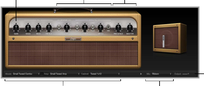
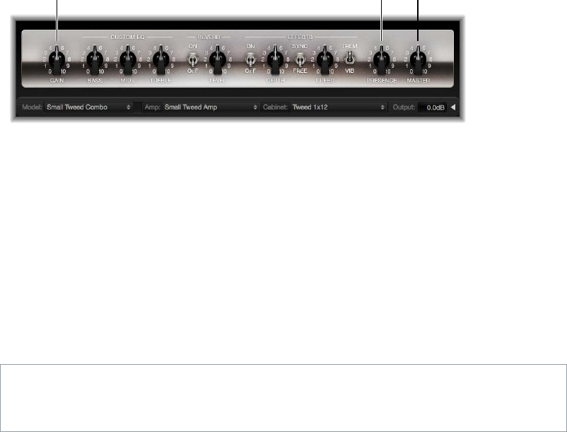
The Amp Designer interface is divided into four main parameter sections.
Model parameters
Output slider
Microphone parameters
Amp
parameters
Effects
parameters
Amp
parameters
•Model parameters: The Model pop-up menu in the black bar at the bottom is used to choose a
precongured model, consisting of an amplier, a cabinet, an EQ type, and a microphone type.
The other pop-up menus in the black bar enable you to independently choose the type of
amplier, cabinet, and microphone. See Build a custom Amp Designer combo on page 18.
•Amp parameters: Located at each end of the knobs section, these parameters are used to
set an amp’s input gain, presence, and output level. See Amp Designer amplier controls on
page 23.
•Eects parameters: Located in the center of the knobs section, these parameters control the
integrated eects. See Amp Designer eects overview on page 24.
•Microphone parameters: Located at the right of the interface, these parameters set the type
and position of the microphone that captures the amplier and cabinet sound. See Amp
Designer microphone parameters on page 26.
•Output slider: The Output slider (or the Output eld, in the small interface) is found at the
lower-right corner of the interface. It serves as the nal level control for Amp Designer’s
output that is fed to the ensuing Insert slots in the channel strip or directly to the channel
strip output.
Note: This parameter is dierent from the Master control, which serves the dual purpose of
sound design as well as controlling the level of the Amp section.
Chapter 1 Amps and pedals 12
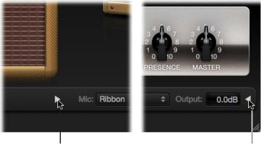
Switch between the full and small versions of the interface
mClick the disclosure triangle between the Cabinet and Mic pop-up menus in the full interface to
switch to the smaller version.
In the small interface you can access all parameters except microphone selection
and positioning.
mTo switch back to the full interface, click the disclosure triangle beside the Output eld in the
small interface.
Click here in
full interface.
Click here in
small interface.
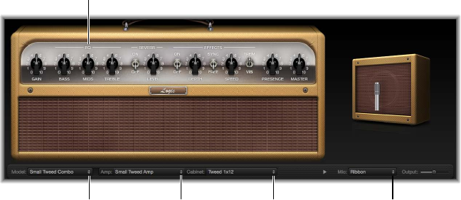
Choose an Amp Designer model
You can use the Model pop-up menu to choose a precongured model, or you can build
a customized model using the Amp, Cabinet, and Mic pop-up menus. See Build a custom
Amp Designer combo. Your choices remain visible in the pop-up menus and they are also
illustrated in the visual display above them. For example, if you choose Tweed 4X10 from the
Cabinet pop-up menu, you see the Tweed cabinet with four 10" speakers on the right side of
the display.
mChoose a precongured model, consisting of an amplier, a cabinet, an EQ type, and a
microphone type, from the Model pop-up menu.

Chapter 1 Amps and pedals 13
Amp Designer models
Tweed Combos
The Tweed models are based on American combos from the 1950s and early 1960s that helped
dene the sounds of blues, rock, and country music. They have warm, complex, clean sounds that
progress smoothly through gentle distortion to raucous overdrive as you increase the gain. Even
after half a century, Tweeds can still sound contemporary. Many modern boutique ampliers are
based on Tweed-style circuitry.
Model Description
Small Tweed Combo A 1 x 12" combo that transitions smoothly from clean
to crunchy, making it a great choice for blues and
rock. For extra denition, set the Treble and Presence
controls to a value around 7.
Large Tweed Combo This 4 x 10" combo was originally intended for
bassists, but it was also used by blues and rock
guitarists. It is more open and transparent-sounding
than the Small Tweed Combo, but it can deliver
crunchy sounds.
Mini Tweed Combo A small amp with a single 10" speaker, used by
countless blues and rock artists. It is quite punchy-
sounding and can deliver the clean and crunch tones
that Tweed combos are known for.
Tip: Tweed combos are responsive to playing dynamics. Adjust the knobs to create a distorted
sound, then reduce the level of your guitar’s volume knob to create a cleaner tone. Turn up your
guitar’s volume knob when soloing.
Classic American Combos
The Blackface, Brownface, and Silverface models are inspired by American combos of the mid
1960s. These tend to be loud and clean with a tight low-end and restrained distortion. They are
useful for clean-toned rock, vintage R & B, surf music, twangy country, jazz, or any other style
where strong note denition is essential.
Model Description
Large Blackface Combo A 4 x 10" combo with a sweet, well-balanced tone
favored by rock, surf, and R & B players. Great for lush,
reverb-saturated chords or strident solos.
Silverface Combo A 2 x 12" combo with a loud, clean tone. It has a
percussive, articulate attack that is suitable for funk,
R & B, and intricate chord work. It can be crunchy
when overdriven, but most players favor it for clean
tones.
Mini Blackface Combo A 1 x 10" combo that is bright and open-sounding,
with reasonable low end impact. It excels at clean
tones with a minimal overdrive.
Small Brownface Combo A 1 x 12" combo that is smooth and rich-sounding,
but retains a level of detail.
Blues Blaster Combo A 1 x 15" combo that has a clear top end with a tight,
dened low end. This model is favored by blues and
rock players.

Chapter 1 Amps and pedals 14
Tip: Although these amps tend toward a clean and tight sound, you can use a Pedalboard
distortion stompbox to attain hard-edged crunch sounds with sharp treble and extended low-
end denition. See Pedalboard distortion pedals on page 45.
British Stacks
The British Stack models are based on the 50- and 100-watt amplier heads that have largely
dened the sound of heavy rock, especially when paired with 4 x 12" cabinets. At medium gain
settings, these amps are suitable for thick chords and ris. Raising the gain yields lyrical solo
tones and powerful rhythm guitar parts. Complex peaks and dips across the tonal spectrum keep
the tones clear and appealing, even when heavy distortion is used.
Model Description
Vintage British Stack Captures the sound of a late 1960s 50-watt amp
famed for its powerful, smooth distortion. Notes retain
clarity, even at maximum gain. After four decades this
remains a denitive rock tone.
Modern British Stack 1980s and 1990s descendants of the Vintage British
amplier head, which were optimized for hard rock
and metal styles of the time. Tonally, it has a deeper
and brighter sound at the low and high end, with a
more “scooped” midrange than the Vintage British
amp.
Brown Stack Unique tones can be coaxed from a British head
by running it at lower voltages than its designers
intended. The resulting “brown” sound—often more
distorted and loose than the standard tone—can add
interesting thickness to a guitar sound.
Tip: The classic British head and 4 x 12" cabinet combo is ideal for ris at high gain levels. These
heads can also sound good through small cabinets, or at clean, low-gain settings.
British Combos
The British Combos capture the brash, treble-rich sound associated with 1960s British rock and
pop. The sonic signature of these amps is characterized by their high-end response, yet they are
rarely harsh-sounding due to a mellow distortion and smooth compression.
Model Description
British Blues Combo This 2 x 12" combo has a loud, aggressive tone that
is cleaner than the British heads, yet delivers rich
distorted tones at high gain settings.
British Combo A 2 x 12" combo based on early 1960s amps. Perfect
for chiming chords and crisp solos.
Small British Combo A 1 x 12" combo with half the power of the British
Combo, this amp oers a darker, less open tone.
Boutique British Combo A 2 x 12" combo that is a modern take on the original
1960s sound. The tone is thicker, with stronger lows
and milder highs than the other British Combos.
Tip: You can often use higher Treble and Presence knob settings with the British Combos than
with other amp types. If the British Blues Combo is too clean for your needs, combine it with
Pedalboard’s Hi Drive stompbox for an aggressive blues tone, or the Candy Fuzz stompbox for a
heavy rock tone. See Pedalboard distortion pedals on page 45.

Chapter 1 Amps and pedals 15
British Alternatives
The late 1960s amplier heads and combos that inspired the Sunshine models are loud and
aggressive, with full mid frequencies. These amps are useful for single note solos, power chords,
and big, open chords—making them popular with the “Brit-pop” bands of the 1990s. The
Stadium amps are famed for their ability to play at extremely high levels without dissolving into
an indistinct distortion. They retain crisp treble and superb note denition, even at maximum
gain settings.
Model Description
Sunshine Stack A robust-sounding head paired with a 4 x 12" cabinet.
It is a good choice for powerful pop-rock chords. If
the tone is too dark, use a high Treble knob setting to
open up the sound.
Small Sunshine Combo A 1 x 12" combo based on a modern amp known for
a “big amp” sound. It is brighter than the Sunshine
Stack head and has tonal qualities similar to the 1960s
British Combo. This amp also sounds good with a 4 x
12" cabinet.
Stadium Stack A classic head and 4 x 12" cabinet conguration
popular with 1970s arena rock bands. Its tones are
cleaner than other Amp Designer 4 x 12" stacks, but it
retains body and impact. A good choice if you need
power and clarity.
Stadium Combo A 2 x 12" combo based on a modern amp. The tone is
smoother than the Stadium Stack.
Tip: The Stadium amps can be slow to distort, so most famous users have paired them with
aggressive fuzz pedals. Try combining them with Pedalboard’s Candy Fuzz or Fuzz Machine
stompboxes. See Pedalboard distortion pedals on page 45.
Metal Stacks
The Metal Stack models are inspired by the powerful, high gain amplier heads favored by
modern hard rock and metal musicians. All are paired with 4 x 12" cabinets. Their signature tones
range from heavy distortion to extremely heavy distortion. These models are ideal if you want
powerful lows, harsh highs, and long sustain in your guitar tones.
Model Description
Modern American Stack A powerful high-gain amp that is ideal for heavy rock
and metal. Use the Mids knob to set the right amount
of scoop or boost.
High Octane Stack Although a powerful, high-gain amp, this model oers
a smooth transition between gain settings and natural
compression. It is a good choice for fast soloing and
for two- or three-note chords.
Turbo Stack An aggressive-sounding amp with spiky highs and
noisy harmonics, especially at high gain settings. Use
the Turbo Stack when you need a guitar tone that
cuts through a mix.
Tip: Combining the Turbo Stack with distortion and fuzz pedals can diminish the amp’s edgy
tone. A dry sound is often the best choice for high-impact ris.

Chapter 1 Amps and pedals 16
Additional Combos
The combos and utility models in this category are versatile amps that you can use for a wide
variety of musical styles.
Model Description
Studio Combo A 1 x 12" combo based on boutique combos of the
1980s and 1990s. These models use multiple gain
stages to generate smooth, sustain-heavy distortion
and bold, bright, clean sounds. Can deliver a heavier
sound when paired with a 4 x 12" cabinet.
Boutique Retro Combo A 2 x 12" combo inspired by expensive modern amps
that combine the sounds of several 1960s combos. It
excels at clean and crunch tones, making it a good
choice when you want an old-fashioned avor but
with the crisp highs and dened lows of a modern
amplier. This model has very sensitive tone controls
that can deliver countless guitar tones.
Pawnshop Combo A 1 x 8" combo based on the inexpensive amps sold
in American department stores in the 1960s. Despite
their limited features and budget workmanship, these
amps are the secret behind the sound of many rock,
blues, and punk players. The clean sounds are warm,
and distorted sounds are thick, despite the small
speaker.
Transparent Preamp A preamp stage with no coloration. Note that
Transparent Preamp is activated in the Amp pop-up
menu, not in the Model pop-up menu.
Tip: Combine the Pawnshop Combo amp with Pedalboard’s Hi Drive or Candy Fuzz stompboxes
to emulate hard rock tones of the late 1960s. See Pedalboard distortion pedals on page 45.
Amp Designer cabinets
This table outlines the properties of each cabinet model available in Amp Designer.
Cabinet Description
Tweed 1 x 12 A 12" open-back cabinet from the 1950s with a warm
and smooth tone.
Tweed 4 x 10 A 4 x 10" open-back cabinet from the late 1950s that
was originally conceived for bassists but that guitarists
use for its sparkling presence.
Tweed 1 x 10 A single 10" open-back combo amp cabinet from the
1950s with a smooth sound.
Blackface 4 x 10 Classic open-back cabinet with four 10" speakers. Its
tone is deeper and darker than the Tweed 4 x 10.
Silverface 2 x 12 An open-back model from the 1960s that provides
low-end punch.
Blackface 1 x 10 An open-back 1960s cabinet with glassy highs and
low/mid body.
Brownface 1 x 12 A balanced 1960s open-back cabinet that is smooth,
transparent, and rich-sounding.
Brownface 1 x 15 This early 1960s open-back cabinet houses the largest
speaker emulated by Amp Designer. Its highs are clear
and glassy, and its lows are tight and focused.

Chapter 1 Amps and pedals 17
Cabinet Description
Vintage British 4 x 12 This late 1960s closed-back cabinet is synonymous
with classic rock. The tone is big and thick yet
also bright and lively, due to the complex phase
cancelations between the four 30-watt speakers.
Modern British 4 x 12 A closed-back 4 x 12" cabinet that is brighter and has
a better low end than the Vintage British 4 x 12, with
less midrange emphasis.
Brown 4 x 12 A closed-back 4 x 12" cabinet with a good low end
and complex midrange.
British Blues 2 x 12 A bright-sounding open-back cabinet with solid lows
and crisp highs, even at high gain settings.
Modern American 4 x 12 A closed-back 4 x 12" cabinet with a full sound. The
lows and mids are denser than the British 4 x 12"
cabinets.
Studio 1 x 12 A compact-sounding open-back cabinet with full
mids and glassy highs.
British 2 x 12 A mid 1960s open-back cabinet with an open, smooth
tone.
British 1 x 12 A small open-back cabinet with crisp highs and low/
mid transparency.
Boutique British 2 x 12 A 2 x 12" cabinet based on the British 2 x 12. It has a
richer midrange and is more powerful in the treble
range.
Sunshine 4 x 12 A 4 x 12" closed-back cabinet with a thick, rich
midrange.
Sunshine 1 x 12 A single 12" open-back combo amp cabinet with
a lively sound that has bright, sweet highs, and
transparent mids.
Stadium 4 x 12 A tight, bright, closed-back British cabinet with bold
upper/mid peaks.
Stadium 2 x 12 A nicely balanced modern British open-back cabinet.
Tonally, it is a compromise between the warmth of the
Blackface 4 x 10 and the brilliance of the British 2 x 12.
Boutique Retro 2 x 12 A 2 x 12" cabinet based on the British 2 x 12. It has
a rich, open midrange and is more powerful in the
treble range.
High Octane 4 x 12 A modern, closed-back European cabinet with strong
lows and highs and scooped mids appropriate for
metal and heavy rock.
Turbo 4 x 12 A modern, closed-back European cabinet with strong
lows, very strong highs, and deeply scooped mids
appropriate for metal and heavy rock.
Pawnshop 1 x 8 A single 8" speaker cabinet that has a strong low-end
punch.
Direct This option bypasses the speaker emulation section.
Tip: A creative sound design option is to choose Direct from the Cabinet pop-up menu, insert
Space Designer in the next free Insert slot, then load one of Space Designer’s “warped” speaker
impulse responses.
Chapter 1 Amps and pedals 18
Build a custom Amp Designer combo
You can use one of the default models or you can create your own hybrid of dierent ampliers,
cabinets, and so on. You create your own by using the Amp, Cabinet, and Mic pop-up menus,
located in the black bar at the bottom of the interface, as well as the EQ pop-up menu,
which you open by clicking the word EQ or Custom EQ above the knobs in the left part of the
knobs section.
Note: If you create your own hybrid amp combo, you can use the Settings pop-up menu to save
it as a setting le, which also includes any parameter changes you have made.
Amp
pop-up menu
Model
pop-up menu
Mic
pop-up menu
Cabinet
pop-up menu
EQ pop-up menu
Choose an Amp Designer amplier
mChoose an amplier from the Amp pop-up menu in the black bar at the bottom of the
Amp Designer interface. See the following sections for details on the characteristics of each
amplier in these categories:
•Tweed Combos on page 13
•Classic American Combos on page 13
•British Stacks on page 14
•British Combos on page 14
•British Alternatives on page 15
•Metal Stacks on page 15
•Additional Combos on page 16
Chapter 1 Amps and pedals 19
Choose an Amp Designer cabinet
Cabinets have a huge impact on the character of a guitar sound (see Amp Designer cabinets on
page 16).
Whereas certain amplier and cabinet pairings have been popular for decades, departing
from them can be an eective way to create fresh-sounding tones. For example, most players
automatically associate British heads with 4 x 12" cabinets. Amp Designer lets you drive a small
speaker with a powerful head, or pair a tiny amp with a 4 x 12" cabinet. You can experiment with
random amplier and cabinet combinations, but you can also make an educated guess about
nontraditional combinations by considering the variables that determine a cabinet’s “sound.”
mChoose a cabinet from the Cabinet pop-up menu in the black bar at the bottom of the
Amp Designer interface. Use the following considerations to guide your decision:
•Combos or Stacks: Combo amps include both an amplier and speakers in a single enclosure.
These usually have an open back, so the sound resonates in multiple directions. The resulting
sound is open—with bright, airy highs and a spacious sound. Amplier stacks consist of
an amplier head, with the speakers in a separate cabinet. These cabinets generally have
a closed back and project the sound forward in a tight, focused beam. They tend to sound
more powerful than open-back cabinets, and typically have a tighter low-end response at the
expense of some high-end transparency.
•Old or New Speakers: Amp Designer models based on vintage cabinets capture the character
of aged speakers. These may be a bit looser and duller sounding than new speakers, but many
players prefer them for their smoothness and musicality. Sounds based on new cabinets tend
to have more snap and bite.
•Large Speakers or Small Speakers: A larger speaker doesn’t guarantee a larger sound. In fact, the
most popular bass guitar cabinet in history uses 8" speakers. You can often get a deeper, richer
tone from a 10" speaker than from a large 4 x 12" cabinet. Try several sizes and choose the one
that works best for your music.
•Single Speakers or Multiple Speakers: Guitarists typically choose cabinets with multiple speakers
for their big sound. The number of speakers is less important than it may appear. Phase
cancelations occur between the speakers, adding texture and interest to the tone. Much of
the “classic rock” sound, for example, is due to tonal peaks and dips caused by interactions
between the speakers in a 4 x 12" cabinet.
Chapter 1 Amps and pedals 20
Choose a microphone type and placement
1 Choose a microphone model from the Mic pop-up menu.
•Condenser models: Emulate the sound of high-end studio condenser microphones. The sound
of condenser microphones is ne, transparent, and well-balanced. Choose Condenser 87 or
Condenser 414.
•Dynamic models: Emulate the sound of popular dynamic cardioid microphones. Dynamic
microphones sound brighter and more cutting than Condenser models. The mid-range is
boosted, with softer lower-mid frequencies, making dynamic microphones a good choice for
rock guitar tones, especially if you want guitars to cut through other tracks in a mix. Choose
Dynamic 20, Dynamic 57, Dynamic 421, or Dynamic 609.
•Ribbon 121: Emulates the sound of a ribbon microphone. A ribbon microphone is a type of
dynamic microphone that captures a sound often described as bright or brittle, yet still warm.
It is useful for rock, crunch, and clean tones.
2 Drag the white dot in the graphic above the Mic pop-up menu to set the microphone position
and distance relative to the cabinet.
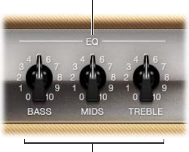
Choose and adjust an EQ type
1 Click the word EQ or CUSTOM EQ above the Bass, Mids, and Treble knobs to open the EQ pop-up
menu, then choose an EQ model. See Amp Designer EQ types on page 22.
2 Rotate the Bass, Mids, and Treble knobs to adjust the EQ model you choose.
Chapter 1 Amps and pedals 21
Amp Designer equalizer
Amp Designer equalizer overview
Hardware amplier tone controls vary among models and manufacturers. For example, the treble
knobs on two dierent models may target dierent frequencies or provide dierent levels of cut
or boost. Some equalizer (EQ) sections amplify the guitar signal more than others, thus aecting
the way the amp distorts.
Amp Designer provides multiple EQ types to mirror these variations in hardware ampliers. All
EQ types have identical controls—Bass, Mids, and Treble—but these controls can behave very
dierently depending on which EQ type you choose.
Selecting an EQ type other than the one traditionally associated with an amplier usually results
in signicant tonal changes. As with hardware ampliers, Amp Designer’s EQs are calibrated to
perform well with particular amplier models. Choosing other EQ types can sometimes produce
a thin or unpleasantly distorted tone.
Despite these less pleasant-sounding possibilities, it is worth experimenting with various
amplier and EQ combinations, because many will sound good together.
EQ pop-up menu
Bass, Mids,
and Treble knobs
EQ parameters
•EQ pop-up menu: Click the word EQ or CUSTOM EQ above the Bass, Mids, and Treble knobs to
open the EQ pop-up menu, which contains the following EQ models: British Bright, Vintage,
U.S. Classic, Modern, and Boutique. Each EQ model has unique tonal qualities that aect the
way the Bass, Mids, and Treble knobs respond. See Amp Designer EQ types on page 22.
•Bass, Mids, and Treble knobs: Rotate to adjust the frequency ranges of the EQ models, similar
to the way you would adjust the tone knobs on a hardware guitar amplier. The behavior and
response of these knobs changes when dierent EQ models are chosen.

Chapter 1 Amps and pedals 22
Amp Designer EQ types
This table describes the properties of each Amp Designer EQ type.
EQ type Description
British Bright Inspired by the EQ of British combo amps of the
1960s, it is loud and aggressive, with stronger highs
than the Vintage EQ. This EQ is useful if you want
more treble denition without an overly clean sound.
Vintage Emulates the EQ response of American Tweed-style
amps and the vintage British stack amps that used a
similar circuit. It is loud and subject to distortion. This
EQ is useful if you want a rougher sound.
U.S. Classic Derived from the EQ circuit of the American Blackface
amps, it has a tone of higher delity than the Vintage
EQ, with tighter lows and crisper highs. This EQ is
useful if you want to brighten your tone and reduce
distortion.
Modern Based on a digital EQ unit popular in the 1980s and
1990s, this EQ is useful for sculpting the aggressive
highs, deep lows, and scooped mids associated with
that era’s rock and metal music styles.
Boutique Replicating the tone section of a “retro modern”
boutique amp, it excels at precise EQ adjustments,
though its tone may be too clean when used with
vintage ampliers. This EQ is a good choice if you
want a cleaner, brighter sound.
Chapter 1 Amps and pedals 23
Amp Designer amplier controls
The amp parameters include controls for the input gain, presence, and master output. The Gain
knob is located to the left in the knobs section, the Presence and Master knobs are to the right,
and the Output parameter is at the lower-right edge of the interface.
Presence
Gain Master
Amplier parameters
•Gain knob: Rotate to set the amount of pre-amplication applied to the input signal. This
control aects specic amp models in dierent ways. For example, when you use the British
Amp, the maximum gain setting produces a powerful crunch sound. When you use the
Vintage British Head or Modern British Head, the same gain setting produces heavy distortion,
suitable for lead solos.
•Presence knob: Rotate to adjust the ultra-high frequency range—above the range of the Treble
control. The Presence parameter aects only the output (Master) stage.
•Master knob: Rotate to set the output volume of the amplier signal sent to the cabinet. For
tube ampliers, increasing the Master level typically produces a compressed and saturated
sound, resulting in a more distorted and louder signal.
WARNING: Because high Master knob settings can produce an extremely loud output that
can damage your speakers or hearing, start with a low Master knob setting and then slowly
increase it.
•Output slider or eld: Drag to set the nal output level of Amp Designer.
Note: The slider is replaced with a eld in the small interface.
Chapter 1 Amps and pedals 24
Amp Designer eects
Amp Designer eects overview
The eects parameters include reverb, tremolo, and vibrato, which emulate the processors found
on many ampliers. These controls are found in the center of the knobs section.
Reverb, which is controlled by an On/O switch in the middle, can be added to either tremolo or
vibrato, or it can be used independently. See Amp Designer reverb eect on page 24.
You can select either Trem(olo), which modulates the amplitude or volume of the sound, or
Vib(rato), which modulates the pitch. See Amp Designer tremolo and vibrato on page 25.
Note: The Eects section is placed before the Presence and Master controls in the signal ow, and
receives the pre-amplied, pre-Master signal.
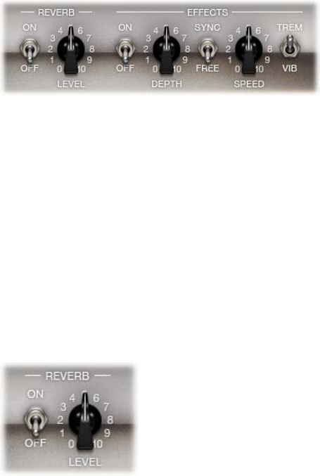
Amp Designer reverb eect
Reverb is always available in Amp Designer, even when you are using a model that is based on
an amplier that provides no reverb function. Reverb is controlled by an On/O switch and a
Level knob in the middle. The Reverb pop-up menu is located above these controls. You can add
Reverb to either the tremolo or vibrato eect, or you can use it independently.
Reverb parameters
•On/O switch: Turns the reverb eect on or o.
•Reverb pop-up menu: Click the word Reverb to open the pop-up menu, which includes the
following reverb types: Vintage Spring, Simple Spring, Mellow Spring, Bright Spring, Dark
Spring, Resonant Spring, Boutique Spring, Sweet Reverb, Rich Reverb, and Warm Reverb. See
Amp Designer reverb types on page 25 for information on these reverb types.
•Level knob: Rotate to set the amount of reverb applied to the pre-amplied signal.
Chapter 1 Amps and pedals 25
Amp Designer reverb types
This table indicates the properties of each Amp Designer reverb type.
Reverb type Description
Vintage Spring This bright, splashy sound has largely dened combo
amp reverb since the early 1960s.
Simple Spring A darker, subtler spring sound.
Mellow Spring An even darker, low-delity spring sound.
Bright Spring Has some of the brilliance of Vintage Spring, but with
less surf-style splash.
Dark Spring A moody-sounding spring. More restrained than
Mellow Spring.
Resonant Spring Another 1960s-style spring with a strong, slightly
distorted midrange emphasis.
Boutique Spring A modernized version of the classic Vintage Spring
with a richer tone in the bass and mids.
Sweet Reverb A smooth modern reverb with rich lows and
restrained highs.
Rich Reverb A rich and balanced modern reverb.
Warm Reverb A lush modern reverb with rich lows/mids and
understated highs.
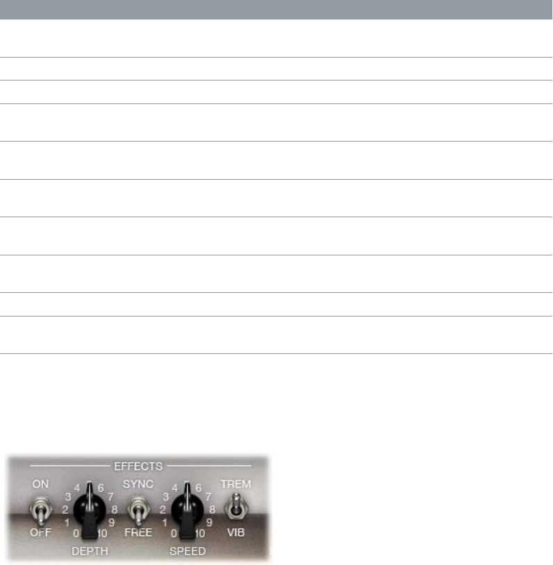
Amp Designer tremolo and vibrato
Tremolo and vibrato are controlled by several switches and two knobs in the eects section.
Tremolo modulates the amplitude or volume of the sound, and Vibrato modulates the pitch of
the sound.
Tremolo and vibrato parameters
•On/O switch: Click to turn the tremolo or vibrato eect on or o.
•Trem(olo)/Vib(rato) switch: Click to choose either tremolo or vibrato.
•Depth knob: Rotate to set the intensity of the modulation for either tremolo or vibrato.
•Speed knob: Rotate to set the speed of the modulation in hertz. Lower settings produce a
smooth, oating sound. Higher settings produce a rotor-like eect.
•Sync/Free switch: Select Sync to synchronize the modulation speed with the host application
tempo. If you select Free, you can use the Speed knob to set the modulation speed to dierent
bar, beat, and musical note values (1/8, 1/16, and so on, including triplet and dotted-note
values).
Chapter 1 Amps and pedals 26
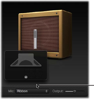
Amp Designer microphone parameters
Amp Designer provides seven virtual microphone types. As with other components in the tone
chain, dierent selections can yield very dierent results. After choosing a cabinet, you can set
the type of microphone to emulate and can place the microphone, relative to the cabinet.
The Mic pop-up menu is near the right end of the black bar. The speaker-adjustment graphic
appears when you move your pointer in the area above the Mic pop-up menu.
Note: The parameters described in this section are accessible only in the full Amp Designer
interface. If you are in the small interface, click the disclosure triangle to the right of the Output
eld to switch to the full interface.
Move your mouse above the
Mic pop-up menu to display the
speaker-adjustment graphic.
Microphone parameters
•Cabinet and speaker-adjustment graphic: By default, the microphone is placed in the center of
the speaker cone (on-axis). This placement produces a fuller, more powerful sound, suitable for
blues or jazz guitar tones. If you place the microphone on the rim of the speaker (o-axis), you
obtain a brighter, thinner tone, making it suitable for cutting rock or R & B guitar parts. Moving
the microphone closer to the speaker emphasizes bass response.
The microphone position is shown on the cabinet and is indicated by the white dot in the
speaker-adjustment graphic. Drag the white dot to change the microphone position and
distance, relative to the cabinet. Placement is limited to near-eld positioning.
•Mic pop-up menu: Choose a microphone model:
•Condenser models: Emulates the sound of high-end studio condenser microphones. The
sound of condenser microphones is ne, transparent, and well-balanced. Choose from:
Condenser 87 and Condenser 414.
•Dynamic models: Emulates the sound of popular dynamic cardioid microphones. Dynamic
microphones sound brighter and more cutting than Condenser models. The mid-range is
boosted, with softer lower-mid frequencies, making dynamic microphones a good choice
for rock guitar tones; useful if you want guitars to cut through other tracks in a mix. Choose
from: Dynamic 20, Dynamic 57, Dynamic 421, and Dynamic 609.
•Ribbon 121: Emulates the sound of a ribbon microphone. A ribbon microphone is a type
of dynamic microphone that captures a sound often described as bright or brittle, yet still
warm. It is useful for rock, crunch, and clean tones.
Tip: Combining multiple microphone types can produce an interesting sound. Duplicate the
guitar track, and insert Amp Designer on both tracks. Select dierent microphones in each
Amp Designer instance while retaining identical settings for all other parameters, then set
track signal levels.
Chapter 1 Amps and pedals 27
Bass Amp Designer
Bass Amp Designer overview
Bass Amp Designer emulates the sound of three famous bass guitar ampliers and the speaker
cabinets used with them. Each precongured model combines an amp and cabinet that
recreates a well-known bass guitar amplier sound. The amp and cabinet can be combined
with integrated compression and EQ units to alter the tone. You can process signals directly,
reproducing the sound of your bass played through these amplication systems. Virtual
microphones are used to pick up the signal of the emulated amplier and cabinet. You can
choose from, and position, three dierent microphone types.
When recording, many bass players use a direct connection to a mixing board or other recording
equipment, often using a passive (non powered) or active (powered) D.I. box (Direct Injection
box). The use of a pre-amp with passive or active EQ and a hardware compressor instead of, or in
addition to, a D.I. box is extremely popular too. Bass Amp Designer emulates a professional-level
American D.I. box.
Bass Amp Designer has a two channel design—one for the pre-amp and one for the D.I. box.
This enables you to exibly change the signal ow for the following playing and recording
congurations: pre-amp with passive or active EQ, compressor, a straight power amp, just the
sound of the cabinets and microphones, D.I. box alone, bass amp alone, or both in parallel. See
Amplier signal ow and Pre-amp signal ow.
Model parameters Microphone parameters
Amp parameters Effects parameters Amp parameters Output slider
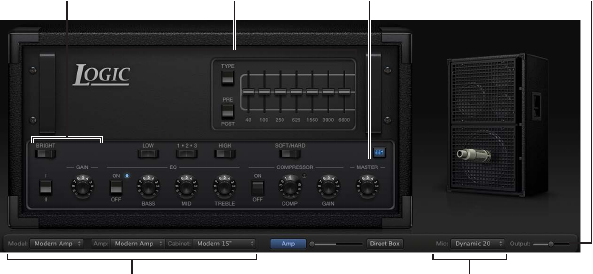
The Bass Amp Designer interface is divided into four main parameter sections.
•Model parameters: The Model pop-up menu at the left of the black bar at the bottom is used
to choose a precongured model, consisting of an amplier, a cabinet, and a microphone type.
The other menus in the black bar enable you to independently choose the type of amplier,
cabinet, and microphone. See Build a custom Bass Amp Designer combo on page 29.
•Amp parameters: Located at each end of the knobs section, these parameters are used to set
an amp’s input gain, presence, and output level. See Bass Amp Designer amplier controls on
page 33.
•Eects parameters: Located in the center of the knobs section, these parameters control the
integrated EQ and compressor eects. A further graphic or parametric EQ is shown above
the compressor controls when the EQ button is turned on. See Bass Amp Designer eects
overview on page 34.
•Microphone parameters: Located at the right of the interface, these parameters set the type
and position of the microphone that captures the amplier and cabinet sound. See Bass Amp
Designer microphone parameters on page 37.

Chapter 1 Amps and pedals 28
•Output slider: The Output slider is found at the lower-right corner of the interface. It serves as
the nal level control for Bass Amp Designer’s output that is fed to the ensuing Insert slots in
the channel strip, or directly to the channel strip output.
Note: This parameter is dierent from the Master control, which serves the dual purpose of
sound design as well as controlling the level of the Amp section.
Choose a Bass Amp Designer model
mChoose a precongured model, consisting of an amplier, a cabinet, and a microphone type,
from the Model pop-up menu.
You can use the Model pop-up menu to choose a precongured model, or you can build a
customized model using the Amp, Cabinet, and Mic pop-up menus. See Build a custom Bass
Amp Designer combo. Your choices remain visible in the pop-up menus, and they are also
illustrated in the visual display above them.
Bass Amp Designer models
Bass amplier models
Bass Amp Designer emulates the three most iconic tube bass amps and cabinets from the 1960s,
1970s, and 1980s. The table includes the cabinets that each amplier is normally matched with.
Amp model Cabinet Description
Classic Amp 8 x 10 inch speakers Emulates a classic six-tube bass
amp with a tuned, closed-back
cabinet introduced in 1960. This
model is good for a range of
musical styles.
Flip Top Amp 1 x 15 inch speaker Emulates a 300-watt tube head
introduced in 1969. It is ideal for
full, fundamental tones.
Modern Amp 3-way speaker array Emulates a 12-tube 360-watt head
introduced in 1989. It is suitable
for many musical styles and is the
ideal choice for highly articulated
performances.

Chapter 1 Amps and pedals 29
Bass cabinet models
The table below outlines the properties of each cabinet model available in Bass Amp Designer.
Cabinet Description
Modern Cabinet 15" 1 x 15 inch speaker, closed-back design. Very deep and
full tone.
Modern Cabinet 10" 1 x 10 inch speaker, closed-back design. A punchy
tone.
Modern Cabinet 6" 1 x 6 inch speaker, closed-back design.
Classic Cabinet 8 X 10" 8 x 10 inch speakers, closed-back design.
Flip Top Cabinet 1 X 15" 1 x 15 inch speaker, closed-back design.
Modern 3 Way 1 x 15 inch speaker, 1 x 10 inch speaker, and 1 x 6 inch
speaker. You can move the microphone vertically and
can position it 20, 30, or 40 cm away from the cabinet.
Direct (PowerAmp Out) A direct signal from the power stage of the emulated
amplier. The cabinet and microphone are removed
from the signal path.
Direct (PreAmp Out) A direct signal from the pre-amplier stage of the
emulated amplier. The cabinet, microphone, and
power amp are removed from the signal path.
Build a custom Bass Amp Designer combo
You can use one of the default models or you can create your own hybrid of dierent ampliers,
cabinets, and so on, using the Amp, Cabinet, and Mic pop-up menus.
Note: If you create your own hybrid amp combo, you can use the Settings pop-up menu to save
it as a setting le, which also includes any parameter changes you have made.
Choose a Bass Amp Designer amplier
mChoose an amplier from the Amp pop-up menu in the black bar at the bottom of the
Amp Designer interface. See Bass amplier models for details on the characteristics of
each amplier.
Choose a Bass Amp Designer cabinet
Cabinets have a huge impact on the character of a bass guitar sound (see Bass cabinet
models on page 29).
Whereas certain amplier and cabinet pairings have been popular for decades, departing from
them is an eective way to create fresh-sounding tones. You can try random combinations, but
if you consider the variables that determine a cabinet’s “sound”, you’ll be able to make educated
guesses about non-traditional amplier and cabinet combinations.
mChoose a cabinet from the Cabinet pop-up menu in the black bar at the bottom of the Bass
Amp Designer interface.
•Old or new speakers: Some Bass Amp Designer models capture the character of aged speakers.
These may be a bit looser and duller sounding than new speakers, but many players prefer
them for their smoothness and musicality. Sounds based on new cabinets tend to have more
snap and bite.
•Large speakers or small speakers: Try several sizes and choose the one that works best for
your music.
Chapter 1 Amps and pedals 30
•Single speakers or multiple speakers: The number of speakers is less important than it may
appear. Phase cancelations occur between the speakers, adding texture and interest to
the tone.
Choose a microphone type and placement
1 Click the Mic pop-up menu to choose a microphone model.
•Condenser 87: Emulates the sound of a high-end German studio condenser microphone. The
sound of condenser microphones is ne, transparent, and well-balanced.
•Dynamic 20: Emulates the sound of popular American dynamic cardioid microphones. This
microphone type sounds brighter and more cutting than the Condenser 87 model. The lower-
mid frequencies are rolled o, making it a good choice for miking rock tones. It is especially
useful if you want your bass guitar part to cut through other tracks in a mix.
•Dynamic 421: Emulates the sound of a German dynamic cardioid microphone. It can capture a
wide frequency range and has a slight emphasis of the treble range. It is useful for clean tones.
2 Drag the white dot in the graphic above the Mic pop-up menu to set the microphone position
and distance relative to the cabinet.
Bass Amp Designer signal ow
Amplier signal ow
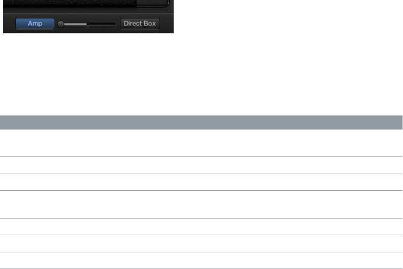
Bass Amp Designer has a two-channel design—one for the pre-amp and one for the D.I. box.
You can use these independently or can blend them by using the controls on the black bar at
the bottom.
Important: The two channels are always used in parallel if the Blend slider is not set to the far
right or to the far left position.
The channel signal ow changes when you choose dierent models from the Cabinet
pop-up menu.
Cabinet Blend slider position Channel 1 routing Channel 2 routing
Any speaker cabinet
model
Middle Pre-amp, power amp,
cabinet, mic
D.I. box
Direct (PowerAmp Out) Middle Pre-amp, power amp D.I. box
Direct (PreAmp Out) Middle Pre-amp D.I. box
Any speaker cabinet
model
Far left Pre-amp, power amp,
cabinet, mic
Direct (PowerAmp Out) Far left Pre-amp, power amp
Direct (PreAmp Out) Far left Pre-amp
Direct (PreAmp Out) Far right D.I. box

Chapter 1 Amps and pedals 31
Pre-amp signal ow
The pre-amp section is very exible, and can be used in several ways when you use dierent
combinations of On/O and Pre/Post switches. The signal ow indicated in the Mode column is
in series when multiple processors are used—that is, the output of one processor signal is fed
into the next processor.
Mode EQ On/O Compressor On/
O
Additional EQ On/
O
Pre/Post switch
All o O O O
EQ only On O O
Compressor only O On O
Additional EQ only O O On
EQ into Compressor
only
On On O
EQ into Additional
EQ only
On O On
Additional EQ into
Compressor only
O On On Pre
Compressor into
Additional EQ only
O On On Post
All on (EQ into
Additional EQ into
Compressor)
On On On Pre
All on (EQ into
Compressor into
Additional EQ)
On On On Post
Chapter 1 Amps and pedals 32
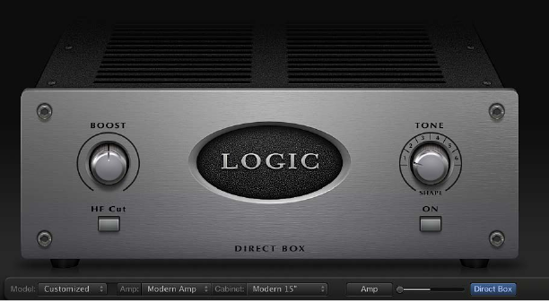
Use the D.I. box
The D.I. box is modeled on a highly regarded American D.I. unit.
D.I. box parameters
•Boost knob: Rotate to set the input gain of the D.I. box.
•HF Cut button: Click to turn on a highpass lter. This is used to reduce noise.
•Tone knob: Rotate to set the tonal color of the D.I. box. Choose from the following preset EQ
curves:
•1: An EQ curve with a -6 dB scoop from 100 Hz to 10 kHz, most pronounced around 800 Hz.
Suitable for acoustic and string instruments, electric bass, and keyboards.
•2: An EQ curve with a very pronounced -24 dB v-shaped notch from 100 Hz to 10 kHz,
centered around 800 Hz. Suitable for electric bass guitar.
•3: An EQ curve with a -3 dB scoop from 100 Hz to 10 kHz, most pronounced around 800 to
1200 Hz. Suitable for acoustics, strings, electric and bass guitar, and keyboards.
•4: An EQ curve with a -3 dB scoop from 1 kHz to 10 kHz, most pronounced around 8
kHz. Frequencies between 60 Hz and 1 kHz have a slight boost of 1 or 2 dB above unity.
Frequencies above 10 kHz have a +3 dB boost. Suitable for acoustics, strings, electric and
bass guitars, and keyboards.
•5: A sloped EQ curve that ramps up from -24 dB at 10 Hz to + 3 dB at around 900 Hz. Suitable
for acoustic and electric guitar.
•6: A sloped EQ curve that ramps up from -24 dB at 10 Hz to +3 dB at around 900 Hz. The
signal rolls o by approximately 6 dB between 10 and 20 kHz. Suitable for electric and
bass guitar.
•Tone on/o button: Click to turn on the tone control.
Use the D.I. box only
mDrag the Blend slider located in the black bar to the far right.
Use the D.I. box and the amplier in parallel
mDrag the Blend slider located in the black bar to any central position—not to the far right or the
far left.
Chapter 1 Amps and pedals 33
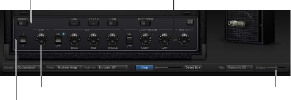
Bass Amp Designer amplier controls
The amp parameters include controls for channel selection, input lter and gain, and master
output. The Gain knob is located to the left in the knobs section and the Master knob and
Output slider are located at the far right.
Bright switch
Gain knob
Channel I/II switch
Master knob
Output slider
Amplier parameters
•Channel I/II switch: Click to switch between channel I and channel II.
•Channel I is active, with a gain of 0 dB.
•Channel II is passive, with a gain of -15 dB.
•Bright switch: Click to switch between normal and bright modes. In the bright position, highs
and upper mids are added to the tone.
Note: The increased mid and high range may lead to a perceived low end roll-o. Use the Bass
EQ knob if you feel the bottom end needs a boost.
•Gain knob: Rotate to set the amount of pre-amplication applied to the input signal. The Gain
knob aects amp models dierently.
•Master knob: Rotate to set the output volume of the amplier signal sent to the cabinet.
Increasing the Master level typically produces a compressed and saturated sound, resulting in
a more distorted and louder signal.
Note: If you choose Direct PowerAmp from the Cabinet pop-up menu, the output signal is
routed directly to the Amp/Direct Box Blend fader. However, if you choose Direct PreAmp from
the Cabinet pop-up menu, the Master knob acts as pre-amp master gain control before the
output signal is routed to the Amp/Direct Box Blend fader.
•Output slider: Drag to set the nal output level of Bass Amp Designer.
Chapter 1 Amps and pedals 34
Bass Amp Designer eects
Bass Amp Designer eects overview
Bass Amp Designer provides multiple EQ types to sculpt your instrument tones.
It provides a basic EQ that mirrors the tonal qualities of the integrated EQ of the amplier model
you choose, if applicable. All amplier model EQs have identical controls: Bass, Mids, and Treble.
See Bass Amp Designer EQ.
Bass Amp Designer also oers an additional Graphic or Parametric EQ that you turn on with the
EQ switch above the Master knob at the far right. See Bass Amp Designer Graphic EQ and Bass
Amp Designer Parametric EQ.
Bass Amp Designer also integrates a dedicated, custom-built compression circuit that is
optimized for electric bass. See Bass Amp Designer compressor.
Bass Amp Designer EQ
The EQ section contains a larger and more inclusive set of the EQ units found in the three
original bass amps emulated by Bass Amp Designer.
EQ parameters
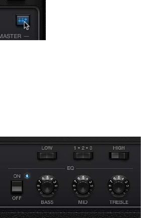
•EQ on/o switch: Click to turn the EQ on or o.
•Bass, Mids, and Treble knobs: Rotate to adjust the frequency ranges of the EQ, similar to the tone
knobs on a hardware amplier.
•Low switch: Click to switch between two positions that aect the tone and behavior of the Bass
EQ knob.
•1-2-3 switch: Click to switch between three positions that aect the tone and behavior of the
Mids EQ knob.
•High switch: Click to switch between two positions that aect the tone and behavior of the
Treble EQ knob.
Chapter 1 Amps and pedals 35
Bass Amp Designer compressor
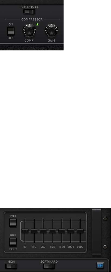
The internal compression circuit is custom-built for use with Bass Amp Designer. It features an
AutoGain function that compensates for volume reductions caused by compression.
Compressor parameters
•Compressor on/o switch: Click to turn the Compressor on or o.
•Fast/Easy switch: Click to switch between two compression algorithms:
•Fast: Stronger compression, with good control over levels, which makes it easier to t the
bass into an arrangement.
•Easy: Compression with a slow attack and longer sustain phase.
•Comp(ression) knob: Rotate to set the amount of compression intensity applied to the
input signal.
•Gain knob: Rotate to add gain to, or subtract gain from, the gain staging of the internal
AutoGain feature.
Note: AutoGain is always active.
Bass Amp Designer Graphic EQ
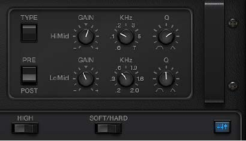
Bass Amp Designer oers an additional Graphic or Parametric EQ that you turn on with the EQ
switch above the Master knob at the far right.
Note: The Graphic EQ in a pre-compressor signal ow is enabled by default.
Graphic EQ parameters
•Type switch: Click the up position to choose the Graphic EQ. Click the down position to choose
the Parametric EQ.
Graphic and Parametric EQ parameter settings are retained when switching between EQ types
and when the additional EQ is turned o. This enables you to quickly make AB comparisons.
•Pre/Post switch: Click to determine if the additional EQ is inserted before or after—pre or
post—the compressor section within the signal ow.
Note: This parameter is relevant only if the Compressor is turned on.
•Frequency sliders: Drag to set the amount of boost or cut for each frequency band.
Chapter 1 Amps and pedals 36
Bass Amp Designer Parametric EQ
Bass Amp Designer oers an additional Graphic or Parametric EQ that you turn on with the EQ
switch above the Master knob at the far right. The Parametric EQ provides two EQ bands:
•HiMid: Controls frequencies in the high and high-mid range.
•LoMid: Controls frequencies in the low and low-mid range.
Parametric EQ parameters
•Type switch: Click the up position to choose the Graphic EQ. Click the down position to choose
the Parametric EQ.
Graphic and Parametric EQ parameter settings are retained when switching between EQ types
and when the additional EQ is turned o. This enables you to quickly make AB comparisons.
•Pre/Post switch: Click to determine if the additional EQ is inserted before or after—pre or
post—the compressor section within the signal ow.
Note: This parameter is relevant only if the Compressor is turned on.
•Gain knobs: Rotate to adjust the amount of cut or boost applied to the frequency range set
with the kHz knob.
•kHz knobs: Rotate to set the frequency range that you want to cut or boost with the Gain knob.
•Q knobs: Rotate to set the width of the band surrounding the frequency set with the
kHz knobs.
The lower the Q knob value, the wider the band, which means that more frequencies will
be aected. The higher the Q knob value, the narrower the band, which means that only the
frequencies nearest to the frequency set with the kHz knob will be aected.
Chapter 1 Amps and pedals 37
Bass Amp Designer microphone parameters
Bass Amp Designer oers three virtual microphone types. As with other components in the tone
chain, dierent selections can yield dierent results. After choosing a cabinet, you can choose the
type of microphone to emulate and you can adjust the position of the microphone, relative to
the cabinet.
The Mic pop-up menu is near the right end of the black bar. The speaker-adjustment graphic
appears when you move your mouse in the area above the Mic pop-up menu.
Move your mouse above the
Mic pop-up menu to display
the speaker-adjustment
graphic.
Microphone parameters
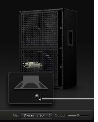
•Cabinet and speaker-adjustment graphic: By default, the microphone is placed in the center
of the speaker cone (on-axis). This placement produces a fuller, more powerful sound. If you
place the microphone on the rim of the speaker (o-axis), you obtain a brighter, thinner tone.
Moving the microphone closer to the speaker emphasizes bass response.
The microphone position is shown on the cabinet and is indicated by the white dot in the
speaker-adjustment graphic. Drag the white dot to change the microphone position and
distance, relative to the cabinet. Placement is limited to near-eld positioning.
•Mic pop-up menu: Choose a microphone model:
•Condenser 87: Emulates the sound of a high-end German studio condenser microphone. The
sound of condenser microphones is ne, transparent, and well-balanced.
•Dynamic 20: Emulates the sound of popular American dynamic cardioid microphones. This
microphone type sounds brighter and more cutting than the Condenser 87 model. The
lower-mid frequencies are rolled o, making it a good choice for miking rock tones. It is
especially useful if you want your bass guitar part to cut through other tracks in a mix.
•Dynamic 421: Emulates the sound of a German dynamic cardioid microphone. It can capture
a wide frequency range and has a slight emphasis of the treble range. It is useful for
clean tones.
Tip: Combining multiple microphone types can produce an interesting sound. Duplicate the
bass guitar track, and insert Bass Amp Designer on both tracks. Select dierent microphones
in each Bass Amp Designer instance while retaining identical settings for all other parameters,
then set track signal levels.
Chapter 1 Amps and pedals 38
Pedalboard
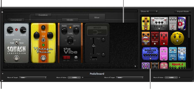
Pedalboard overview
Pedalboard simulates the sound of a number of famous “stompbox” pedal eects. You can
process any audio signal with a combination of stompboxes.
You can add, remove, and reorder pedals. The signal ow runs from left to right in the Pedal
area. The addition of two discrete busses, coupled with splitter and mixer units, enables you to
experiment with sound design and precisely control the signal at any point in the signal chain.
All stompbox knobs, switches, and sliders can be automated. Eight Macro controls enable real-
time changes to any pedal parameter with a MIDI controller.
Macro Controls area
Routing area
Pedal Browser
Pedal area
•Pedal Browser: Shows all pedal eects and utilities. These can be dragged into the Pedal area as
part of the signal chain. See Use the Pedal Browser on page 39. This interface area is also used
for the alternative import mode. See Use Pedalboard’s import mode on page 40.
•Pedal area: This is where you determine the order of eects and set eect parameters. You can
add, replace, and remove stompboxes here. See Use the Pedal area on page 41.
•Router: Used to control signal ow in the two eects busses (Bus A and Bus B) available in
Pedalboard. See Use Pedalboard’s Router on page 42.
•Macro Controls: Used to assign eight MIDI controllers, which can be used to control any
stompbox parameter in real time. See Use Pedalboard’s Macro Controls on page 44.
Chapter 1 Amps and pedals 39
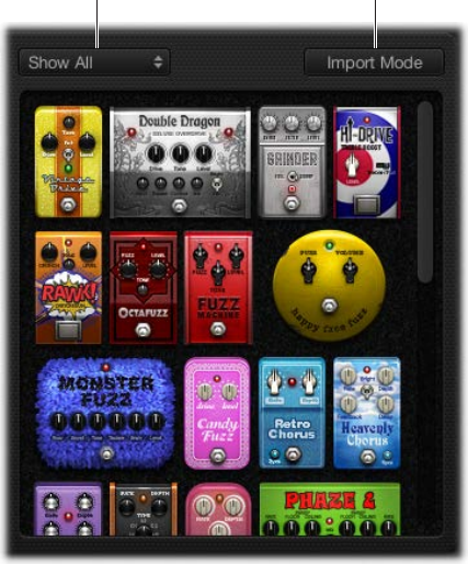
Use the Pedal Browser
Pedalboard oers dozens of pedal eects and utilities in the Pedal Browser on the right side of
the interface. Each eect and utility is grouped into a category, such as distortion, modulation,
and so on. The eect and utility pedals are described in the following sections:
•Pedalboard distortion pedals on page 45
•Pedalboard modulation pedals on page 46
•Pedalboard delay pedals on page 50
•Pedalboard lter pedals on page 51
•Pedalboard dynamics pedals on page 51
•Pedalboard utility pedals on page 52
View pop-up menu Import Mode button
Hide or show the Pedal Browser
mClick the disclosure triangle in the lower-right corner of the Pedal area.
Show specic pedal groups in the Pedal Browser
mChoose Distortion, Modulation, Delay, Filter, Dynamics, or Utility from the View pop-up menu.
The Pedal Browser shows only the stompboxes within the category you choose.
To show all the pedal groups, choose Show All from the View pop-up menu.
Add a stompbox to the Pedal area
Do one of the following:
mDrag the eect that you want to insert from the Pedal Browser to the appropriate Pedal area
position. This can be to the left, to the right, or in between existing pedals.
mDouble-click an eect in the Pedal Browser to add it to the right of all existing stompboxes in the
Pedal area.
Note: Double-clicking a stompbox in the Pedal Browser when a stompbox is selected in the
Pedal area replaces the selected pedal.
Chapter 1 Amps and pedals 40
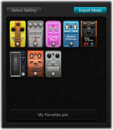
Use Pedalboard’s import mode
Pedalboard has a feature you can use to import parameter settings for each type of pedal. In
contrast to the plug-in window Settings pop-up menu, which you use to load a setting for the
entire Pedalboard plug-in, this feature can be used to load a setting for a specic stompbox type.
Turn import mode on or o
mClick the Import Mode button to show all pedals used in the most recent Pedalboard setting.
When the Import Mode button is active, the Pedal Browser switches to an alternate view mode
that displays imported settings. When import mode is inactive, the normal Pedal Browser view
is shown.
Import pedal settings into the Pedal Browser
1 Click the Import Mode button to activate import mode.
Note that the View menu changes to the Select Setting button.
Note: If this is your rst attempt to import settings, a dialog opens where you can select a setting
to import.
2 Click the Select Setting button and select a setting, then click Open.
Depending on the setting you chose, one or more stompboxes appear in the Pedal Browser. The
name of the imported setting is shown at the bottom of the Pedal Browser.
Add an imported pedal to the Pedal area
Do one of the following:
mDrag the stompbox that you want to add from the Pedal Browser to the appropriate Pedal area
position. This can be to the left, to the right, or in between existing pedals.
mMake sure that no pedal is selected in the Pedal area, then double-click a stompbox in the Pedal
Browser to add it to the right of all existing eects in the Pedal area.
Note: The parameter settings of pedals added in import mode are also imported.
Chapter 1 Amps and pedals 41
Replace a pedal setting in the Pedal area with an imported pedal setting
1 Click the pedal you want to replace in the Pedal area.
It is highlighted with a blue outline.
2 Click the stompbox in the Pedal Browser to replace the selected pedal (or pedal setting) in the
Pedal area.
The blue outlines of the selected pedal in the Pedal area and Pedal Browser blink on and o to
indicate an imported setting. The setting name area at the bottom of the Pedal Browser displays
“Click selected item again to revert.”
Note: If you want to make your replacement permanent, click the background in the Pedal
Browser, or click the Import Mode button.
3 To restore the selected pedal’s previous setting, click the highlighted stompbox in the Pedal
Browser. The Import Mode button and the outline of the selected pedal (in the Pedal area)
become solidly highlighted, indicating that the original setting has been restored.
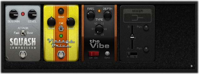
Use the Pedal area
Pedalboard’s stompbox eect pedals not only resemble their physical counterparts; they are also
used in much the same way, albeit without patch cords, power supplies, and screws or locking
mechanisms. The Pedal area layout mirrors a traditional pedalboard, with signals running from
left to right.
Add a pedal to the Pedal area
Do one of the following:
mDrag the stompbox that you want to insert from the Pedal Browser to the appropriate Pedal area
position. This can be to the left, to the right, or in between existing pedals.
mMake sure that no pedal is selected in the Pedal area, then double-click a stompbox in the Pedal
Browser to add it to the right of all existing eects in the Pedal area.
Note: You insert Mixer and Splitter utility pedals in a dierent way. See Use Pedalboard’s
Router on page 42.
Change an eect pedal position in the Pedal area
mDrag the stompbox to a new position, either to the right or the left.
Automation and bus routings, if active, are moved with the eect pedal. For information about
automation and bus routings, see Use Pedalboard’s Router on page 42.
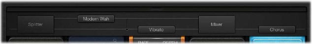
Chapter 1 Amps and pedals 42
Replace a pedal in the Pedal area
Do one of the following:
mDrag the stompbox from the Pedal Browser directly over the pedal you want to replace in the
Pedal area.
mClick to select the stompbox you want to replace in the Pedal area, then double-click the
appropriate pedal in the Pedal Browser.
Note: You can replace “eect” pedals, but not the Mixer or Splitter utilities. Bus routings, if active,
are not changed when an eect pedal is replaced. See Use Pedalboard’s Router on page 42.
Remove a pedal from the Pedal area
Do one of the following:
mDrag the pedal out of the Pedal area.
mClick the pedal to select it, and press the Delete key.
Use Pedalboard’s Router
Pedalboard has two discrete signal busses—Bus A and Bus B—that appear as two horizontal
gray lines in the Router above the Pedal area. These busses provide a great deal of exibility
when you are setting up signal processing chains. All stompboxes that you drag into the Pedal
area are inserted into Bus A—the lower of the two lines—by default.
Note: The Router area appears when you move your pointer to a position immediately above the
Pedal area, and it disappears when you move the pointer away. When you create a second bus
routing, the Router remains open even when your pointer is not over it. You can close the Router
by clicking the small latch button at the top; the Router then opens or closes automatically when
you move your pointer over it.
Notes on Splitter utility and Mixer utility use
Dragging a Splitter utility into the Pedal area automatically inserts a Mixer utility to the far right
of all inserted pedals.
You cannot drag a Splitter utility to the far right of all inserted pedals, to directly after an inserted
Splitter utility, to directly in front of an inserted Mixer utility, or to an empty space in the Pedal
area.
Dragging a Mixer utility into the Pedal area automatically creates a split point at the earliest
possible point—the leftmost point—within the signal chain.
You cannot drag a Mixer utility to the rst slot in the Pedal area, to between an inserted Splitter
and Mixer utility combination, or directly to the right of an inserted Mixer utility.
Chapter 1 Amps and pedals 43
Create a second bus routing
Do one of the following:
mMove your pointer immediately above the Pedal area to open the Router, and click the name of a
stompbox in the Router.
Two gray lines appear in the Router—the lower one representing Bus A and the upper one Bus
B—and the pedal name moves to the upper line. The chosen stompbox is now routed to Bus B,
and a Mixer utility pedal is automatically added to the end of the signal chain.
mDrag a Splitter utility pedal into the Pedal area when more than one pedal is inserted.
This also inserts a Mixer at the end of the signal chain if one doesn’t already exist.
Remove the second bus routing
Do one of the following:
mDelete the Mixer and Splitter utility pedals from the Pedal area.
mRemove all stompboxes from the Pedal area. This automatically removes any Mixer utility.
Remove an eect from the second bus
mClick the name of the pedal in the Router. (You can also click the lower gray line immediately
above the pedal to remove the pedal from the second bus.)
Note: The removal of all eects from Bus B does not remove the second bus. The Mixer utility
pedal remains in the Pedal area, even when a single stompbox (eect) is in the Pedal area. This
enables parallel routing of wet and dry signals. Only when all pedal eects are removed from the
Pedal area are the Mixer utility and second bus removed.
Determine the split point between busses
When more than one bus is active, a number of dots appear along the “cables”—the gray lines—
in the Router. These represent the output (the socket) of the pedal to the lower left of the dot.
mClick the appropriate dot to determine the split point—the point where the signal is routed
between busses.
A cable appears between the busses when you click a dot.
Note: You cannot create a split point directly before or after the Mixer utility.
Switch between a Splitter utility and a bus split point
mTo replace a bus split point with a Splitter utility: Double-click the bus split point dot in the Router.
The Splitter utility appears in the Pedal area.
mTo replace a Splitter utility with a bus split point: Double-click the Splitter label in the Router.
The Splitter utility is removed from the Pedal area.
Change a Mixer utility position in the Pedal area
mDrag the Mixer utility to a new position, either to the left or to the right.
If you move the Mixer utility to the left, the “downmix” of Bus A and Bus B occurs at the earlier
insertion point. Relevant eect pedals are moved to the right and are inserted into Bus A.
If you move the Mixer utility to the right, the “downmix” of Bus A and Bus B occurs at the later
insertion point. Relevant eect pedals are moved to the left and are inserted into Bus A.
Note: A Mixer pedal cannot be moved to a position directly following or preceding a
corresponding split point or Splitter utility.
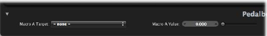
Chapter 1 Amps and pedals 44
Change a Splitter utility position in the Pedal area
mDrag the Splitter utility to a new position, either to the left or to the right.
If you move the Splitter utility to the left, the split between Bus A and Bus B occurs at the earlier
insertion point. Relevant eect pedals are moved to the right and are inserted into Bus A.
If you move the Splitter utility to the right, the split between Bus A and Bus B occurs at the later
insertion point. Relevant eect pedals are moved to the left and are inserted into Bus A.
Note: A Splitter pedal cannot be moved to a position directly preceding (or to the right of) a
corresponding Mixer utility.
Use Pedalboard’s Macro Controls
Pedalboard provides eight Macro Targets—A through H—that are found in the Macro Controls
area below the Pedal area. These enable you to map any parameter of an inserted stompbox as a
Macro A–H target. You can save dierent mappings with each Pedalboard setting.
In Logic Pro X, you use a controller assignment or create a Workspace knob for “Macro A–H
Value.” MIDI hardware switches, sliders, or knobs can then be used to control the mapped
Pedalboard Macro A–H target parameters in real time. See the Logic Pro X Help for details.
Click the disclosure triangle at the bottom left to hide or show the Macro Controls area.
•Macro A–H Target pop-up menus: Determine the parameter that you want to control with a
MIDI controller.
•Macro A–H Value sliders and elds: Set, and display, the current value for the parameter chosen
from the corresponding Macro Target pop-up menu.
Assign a Macro A–H Target
Do one of the following:
mChoose the parameter that you want to control from any of the Macro A–H Target pop-up
menus.
Each stompbox parameter is shown in the following way: “Slot number—Pedal Name—
Parameter”—for example, “Slot 1—Blue Echo—Time,” or “Slot 2—Roswell Ringer—Feedback.”
The Slot number refers to the position among the pedals, as they appear from left to right in the
Pedal area.
mChoose the “Auto assign” item from any Macro A–H Target pop-up menu, then click the
appropriate parameter in any inserted pedal.
Note: The chosen parameter is displayed in the Macro A–H Target pop-up menu.

Chapter 1 Amps and pedals 45
Pedalboard distortion pedals
This table below describes the distortion eects pedals.
Stompbox Description
Candy Fuzz A bright, “nasty” distortion eect. Drive controls the
input signal gain. Level sets the eect volume.
Double Dragon A deluxe distortion eect. It oers independent level
controls for input (Input) and output (Level). Drive
controls the amount of saturation applied to the
input signal. The Tone knob sets the cuto frequency.
The Squash knob sets the threshold for the internal
compression circuit. Contour sets the amount of
nonlinear distortion applied to the signal. Mix sets the
ratio between the source and distorted signals. The
Bright/Fat switch changes between two xed, high
shelving lter frequencies. Blue and red LEDs indicate
the Bright and Fat switch positions, respectively.
Fuzz Machine An American “fuzz” distortion eect. Fuzz controls
the input gain. Overall output gain is set with Level.
The Tone knob increases treble, while simultaneously
reducing low frequencies, as you move it to higher
values.
Grinder Grinder is a lo-, dirty “metal” distortion. Grind sets
the amount of drive applied to the input signal.
Tone is controlled with the Filter knob, making the
sound harsher and more crunchy at higher values.
The Full/Scoop switch alternates between two xed
Gain/Q lter settings. At the Full position, ltering is
less pronounced than at the Scoop position. Overall
output level is controlled with the Level knob.
Grit A hard and nasty ltered distortion eect that sounds
great on keyboards and guitars.
Happy Face Fuzz A softer, full-sounding distortion eect. Fuzz sets the
amount of saturation applied to the input signal.
Volume sets the output level.
Hi-Drive An overdrive eect that can emphasize high
frequency content in the signal. Level controls the
eect output. The Treble/Full switch sets a xed
shelving frequency, allowing either the treble portion
or the full range input signal to be processed.
Monster Fuzz A saturated, slightly harsh distortion. Roar sets the
amount of gain applied to the input signal. Growl
sets the amount of saturation. Tone sets the overall
color of the distortion. Higher Tone values increase
the treble content of the signal, but there is a
corresponding decrease in overall volume. Texture
can smooth out or roughen up the distortion. Grain
sets the amount of nonlinear distortion applied to the
signal. The eect output is controlled with the Level
knob.
Octafuzz A fat fuzz eect that can deliver a soft, saturated
distortion. Fuzz controls the input gain. Level sets the
ratio between the distorted and source signals. The
Tone knob sets the cuto frequency of the highpass
lter.

Chapter 1 Amps and pedals 46
Stompbox Description
Rawk! Distortion A metal/hard rock distortion eect. Crunch sets the
amount of saturation applied to the input signal.
Output gain is set with Level. Tonal color is set with
the Tone knob, making the sound brighter at higher
values.
Tube Burner A vacuum tube-based distortion that provides a wide
palette of sounds, ranging from warm grain to crispy
overdrive.
Vintage Drive Overdrive eect that emulates the distortion
produced by a eld-eect transistor (FET), commonly
used in solid-state ampliers. When saturated, FETs
generate a warmer sounding distortion than bipolar
transistors, such as those emulated by Grinder. Drive
sets the saturation amount for the input signal. Tone
sets the frequency for the high cut lter, resulting in
a softer or harsher tone. The Fat switch, when at the
top position, enhances lower frequency content in the
signal. Level sets the overall output level of the eect.
Pedalboard modulation pedals
This table describes the modulation eects pedals.
Stompbox Description
Dr Octave A classic octaver eect with two independent octave
controls plus an integrated overdrive.
Flange Factory A deluxe anging eect that allows precise control of
every aspect of your sound.
Heavenly Chorus A rich, sweet-sounding chorus eect that thickens
the sound. Rate sets the modulation speed and can
either run freely or be synchronized with the host
application tempo when you enable the Sync button.
When synchronized, you can specify bar, beat, and
note values, including triplets and dotted notes.
Depth sets the strength of the eect. Feedback sends
the output of the eect back in to the input, further
thickening the sound or leading to intermodulations.
Delay sets the ratio between the original and eect
signals. The upper Bright switch position applies
a xed frequency internal EQ to the signal. At the
bottom position, the EQ is bypassed.
Phase Tripper A simple phasing eect. Rate sets the modulation
speed and can either run freely or be synchronized
with the host application tempo when you enable the
Sync button. When synchronized, you can specify bar,
beat, and note values, including triplets and dotted
notes. Depth sets the strength of the eect. Feedback
determines the amount of eect signal that is routed
back into the input. This can change the tonal color,
make the sweeping eect more pronounced, or do
both.

Chapter 1 Amps and pedals 47
Stompbox Description
Phaze 2 A exible dual-phaser eect. LFO 1 and LFO 2 Rate
set the modulation speed and can run freely, or
be synchronized with the host application tempo
when you enable the Sync button. Ceiling and Floor
determine the frequency range that is swept. Order
switches between dierent algorithms, with higher
(even) numbers resulting in a heavier phasing eect.
Odd order numbers result in more subtle comb-
ltering eects. Feedback determines the amount of
eect signal that is routed back into the input. This
can change the tonal color, make the phasing eect
more pronounced, or do both. Tone works from the
center position; turn it to the left to increase the
amount of lowpass ltering, or turn it to the right to
increase the amount of highpass ltering. Mix sets the
level ratio between each phaser.
Retro Chorus A subtle, vintage chorus eect. Rate sets the
modulation speed and can either run freely or be
synchronized with the host application tempo when
you enable the Sync button. When synchronized,
you can specify bar, beat, and note values, including
triplets and dotted notes. Depth sets the strength of
the eect.
Robo Flanger Flexible anging eect. Rate sets the modulation
speed and can either run freely or be synchronized
with the host application tempo when you enable the
Sync button. When synchronized, you can specify bar,
beat, and note values, including triplets and dotted
notes. Depth sets the strength of the eect. Feedback
determines the amount of eect signal that is routed
back into the input. This can change the tonal color,
make the anging eect more pronounced, or do
both. The Manual knob sets a delay time between the
source and eect signals. This can result in anger-
chorus eects, or in metallic-sounding modulations,
particularly when used with high Feedback values.
Roswell Ringer A ring modulation eect that can make incoming
audio sound metallic, or unrecognizable, and can
deliver tremolos, brighten up signals, and more. The
Freq knob sets the core lter cuto frequency. Fine
is a ne tuning knob for the lter frequency. The
Lin/Exp switch determines if the frequency curve is
linear—with 12 notes per octave—or exponential. FB
(feedback) determines the amount of eect signal
that is routed back into the input. This can change
the tonal color, make the eect more pronounced,
or do both. Balance between the original and eect
signals is set with the Mix knob. See Ringshifter
overview on page 206 for background information on
ring modulation.

Chapter 1 Amps and pedals 48
Stompbox Description
Roto Phase A phaser eect that adds movement to, and alters the
phase of, the signal. Rate sets the modulation speed
and can either run freely or be synchronized with the
host application tempo when you enable the Sync
button. When synchronized, you can specify bar, beat,
and note values, including triplets and dotted notes,
with the Rate knob. Intensity sets the strength of the
eect. The Vintage/Modern switch activates a xed-
frequency internal EQ when switched to Vintage and
deactivates it when switched to Modern.
Spin Box Emulation of a Leslie rotor speaker cabinet, commonly
used with the Hammond B3 organ. Cabinet sets the
type of speaker box. Fast Rate sets the maximum
modulation speed—this applies only when the Fast
button is active. Response determines the amount
of time required for the rotor to reach its maximum
and minimum speed. Drive increases the input gain,
introducing distortion to the signal. The Bright switch
activates a high shelving lter when turned on. The
Slow, Brake, and Fast buttons determine how the
“speaker” behaves: Slow rotates the speaker slowly;
Fast rotates the speaker quickly, up to the maximum
speed determined by the Fast Rate knob; and Brake
stops the speaker rotation. See Rotor Cabinet eect
overview on page 212 for background information on
the Leslie eect.
Total Tremolo A exible tremolo eect—modulation of the signal
level. Rate sets the modulation speed and can
either run freely or be synchronized with the host
application tempo when you enable the Sync button.
When synchronized, you can specify bar, beat, and
note values, including triplets and dotted notes. Depth
sets the strength of the eect. Wave and Smooth work
in combination to change the LFO waveform shape.
This enables you to create oating changes in level,
or abrupt steps. Volume determines the output level
of the eect. The 1/2 Speed and 2x Speed buttons
immediately halve or double the current Rate value.
Hold down the Speed Up and Slow Down buttons to
gradually accelerate or reduce the current Rate value
to the maximum or minimum possible values.
Trem-o-Tone A tremolo eect—modulation of the signal level.
Rate sets the modulation speed and can either run
freely or be synchronized with the host application
tempo when you enable the Sync button. When
synchronized, you can specify bar, beat, and note
values, including triplets and dotted notes. Depth sets
the strength of the eect. Level sets the post-tremolo
gain.

Chapter 1 Amps and pedals 49
Stompbox Description
the Vibe A vibrato/chorus eect based on the Scanner Vibrato
unit found in the Hammond B3 organ. You can choose
from three vibrato (V1–3) or chorus (C1–3) variations
with the Type knob. Rate sets the modulation speed
and can either run freely or be synchronized with
the host application tempo when you enable the
Sync button. When synchronized, you can specify bar,
beat, and note values, including triplets and dotted
notes. Depth sets the strength of the eect. See
Scanner Vibrato eect on page 216 for background
information on this eect.
Wham A pedal-controlled pitch shifter. Mix sets the level
balance between the source and pitch-shifted signals.

Chapter 1 Amps and pedals 50
Pedalboard delay pedals
This table describes the Delay eects pedals.
Stompbox Description
Blue Echo A delay eect. Time sets the modulation speed and
can either run freely or be synchronized with the
host application tempo when you enable the Sync
button. When synchronized, you can specify bar, beat,
and note values, including triplets and dotted notes.
The Repeats knob determines the number of delay
repeats. Mix sets the balance between the delayed
and source signals. The Tone Cut switch controls a
xed frequency internal lter circuit that allows more
low (Lo) or high (Hi) frequency content to be heard.
You can also disable this lter circuit by choosing O.
Through passes the source signal through to the next
pedal, while delay repeats continue.
Spring Box A spring reverb pedal. Time sets the length of the
reverberation to short, medium, or long values.
Tone controls the cuto frequency, making the
eect brighter or darker. Style switches between
algorithms, each with dierent characteristics. You can
choose Boutique, Simple, Vintage, Bright, or Resonant.
Mix sets the ratio between the source and eect
signals.
Tie Dye Delay A warm-sounding reverse delay eect that is perfect
for fans of 1960s and 1970s psychedelic rock.
Tru-Tape Delay A vintage tape delay eect. The Norm/Reverse switch
changes the delay playback direction. Reverse mode is
indicated by a blue LED and Normal mode is indicated
by a red LED. Hi Cut and Lo Cut activate a xed
frequency lter. Dirt sets the amount of input signal
gain, which can introduce an overdriven, saturated
quality. Flutter emulates speed uctuations in the
tape transport mechanism. Time sets the modulation
speed and can either run freely or be synchronized
with the host application tempo when you enable the
Sync button. When synchronized, you can specify bar,
beat, and note values, including triplets and dotted
notes. Feedback determines the amount of eect
signal that is routed back into the input. The buildup
of repeating signals can be used creatively for dub-
delay and other eects by adjusting Feedback in real
time. Mix sets the balance between the source and
eect signals.

Chapter 1 Amps and pedals 51
Pedalboard lter pedals
This table describes the lter eects pedals.
Stompbox Description
Auto-Funk An auto-wah (lter) eect. Sensitivity sets a threshold
that determines how the lter responds to incoming
signal levels. Cuto sets the center frequency for the
lter. The BP/LP switch enables either a bandpass or
lowpass lter circuit. Signal frequencies just above and
below the cuto point are ltered when the BP switch
position is chosen. When the LP switch position is
active, only signals below the cuto point are allowed
through the lter. The Hi/Lo switch determines one of
two preset (lter) resonance settings. The Up/Down
switch activates a positive or negative modulation
direction—the “wah” ltering occurs above or below
the source signal frequency.
Classic Wah A funky wah eect, straight from 1970s TV police show
soundtracks. You control it by dragging the pedal.
Graphic EQ A classic 7-band EQ pedal.
Modern Wah A more aggressive wah eect. You control it by
dragging the pedal. Mode enables you to choose
from the following: Retro Wah, Modern Wah, Opto
Wah 1, Opto Wah 2, Volume. Each has a dierent
tonal quality. The Q knob determines the resonant
characteristics. Low Q values aect a wider frequency
range, resulting in softer resonances. High Q values
aect a narrower frequency range, resulting in more
pronounced emphasis.
Pedalboard dynamics pedals
This table describes the dynamics pedals.
Stompbox Description
Squash Compressor A simple compressor. Sustain sets the threshold
level. Signals above this are reduced in level. Level
determines the output gain. The Attack switch can
be set to Fast for signals with fast attack transients,
such as drums, or to Slow for signals with slow attack
phases, such as strings.

Chapter 1 Amps and pedals 52
Pedalboard utility pedals
This table describes the parameters of the Mixer and Splitter pedals.
Stompbox Description
Mixer Controls the level relationship between Bus A and
Bus B signals. It can be inserted anywhere in the
signal chain but is typically used at the end of the
chain—at the extreme right of the Pedal area. See Use
Pedalboard’s Router on page 42 for more information.
The A/Mix/B switch solos the “A” signal, mixes the “A”
and “B” signals, or solos the “B” signal. The level setting
of the Mix fader is relevant for all A/Mix/B switch
positions.
In stereo instances, the Mixer utility also provides
discrete Pan controls for each bus.
Splitter A utility that can be inserted anywhere in the signal
chain. Splitter has two modes:
Freq: Works as a frequency-dependent signal splitter
that divides the incoming signal. Signals above the
frequency set with the Frequency knob are sent to
Bus B. Signals below this frequency are sent to Bus A.
Split: The incoming signal is routed equally to both
buses. The Frequency knob has no impact in this
mode.
See Use Pedalboard’s Router on page 42 for more
information.
53
Delay eects overview
Delay eects store the input signal—and hold it for a short time—before sending it to the eect
input or output.
The held, and delayed, signal is repeated after a given time period, creating a repeating echo
eect. Each subsequent repeat is a little quieter than the previous one. Most delays also allow
you to feed a percentage of the delayed signal back to the input. This can result in a subtle,
chorus-like eect or cascading, chaotic audio output.
The delay time can often be synchronized to the project tempo by matching the grid resolution
of the project, usually in note values or milliseconds.
You can use delays to double individual sounds to resemble a group of instruments playing the
same melody, to create echo eects, to place the sound in a large “space,” to generate rhythmic
eects, or to enhance the stereo position of tracks in a mix.
Delay eects are generally used as channel insert or bussed eects. They are rarely used on an
overall mix (in an output channel), unless you’re trying to achieve an unusual eect.
Delay eects 2
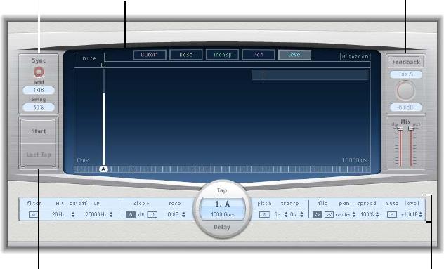
Chapter 2 Delay eects 54
Delay Designer
Delay Designer overview
Delay Designer is a multitap delay. Unlike traditional delay units that oer only one or two delays
(or taps) that may or may not be fed back into the circuit, Delay Designer provides up to 26
individual taps. These taps are all fed from the source signal and can be edited to create unique
delay eects.
Delay Designer provides control over the level, pan position, and pitch of each tap. Each tap can
also be lowpass or highpass ltered.
Further eect-wide parameters include synchronization, quantization, and feedback.
As the name implies, Delay Designer oers signicant sound design potential. You can use it
for everything from a basic echo eect to an audio pattern sequencer. You can create complex,
evolving, moving rhythms by synchronizing the placement of taps. This leads to further musical
possibilities when coupled with judicious use of transposition and ltering. Alternatively, you can
set up numerous taps as repeats of other taps, much as you would use the feedback control of a
simple delay eect, but with individual control over each repeat.
Tap pads
Master section
Sync section
Tap parameter bar
Main display
The Delay Designer interface consists of ve main sections:
•Main display: Provides a visual representation of all taps. You can see and edit the parameters
of each tap in this area. See Delay Designer main display on page 55.
•Tap parameter bar: Oers a numeric overview of the current parameter settings for the
selected tap. You can view and edit the parameters of each tap in this area. See Delay Designer
Tap parameter bar on page 68.
•Tap pads: You can use these two pads to create taps in Delay Designer. See Create taps in
Delay Designer on page 59.
•Sync section: You can set all Delay Designer synchronization and quantization parameters in
this area. See Delay Designer sync mode on page 69.
•Master section: This area contains the global Mix and Feedback parameters. See Delay Designer
master parameters on page 70.
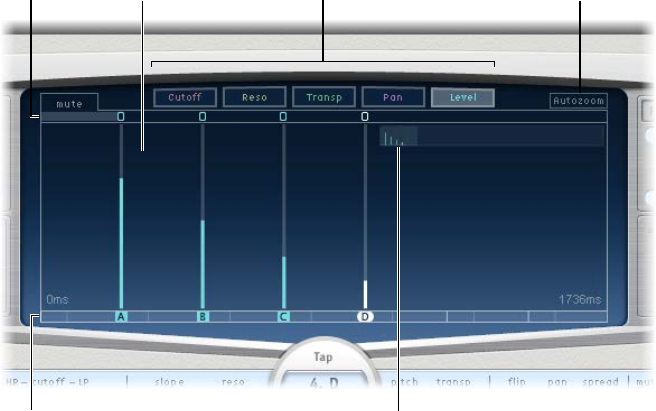
Chapter 2 Delay eects 55
Delay Designer main display
Delay Designer’s main display is used to view and edit tap parameters. You can choose the
parameter to show and quickly zoom or navigate through all taps.
View buttons
Overview display
Autozoom buttonToggle buttons
Identification bar
Tap display
Main display parameters
•View buttons: Click to choose the parameter or parameters shown in the Tap display. See Use
the Delay Designer Tap display.
•Autozoom button: Zooms the Tap display out, making all taps visible. Turn Autozoom o if
you want to zoom the display in (by dragging vertically in the Overview display) to view
specic taps.
•Overview display: Shows all taps in the time range.
•Toggle buttons: Click to turn the parameters of a particular tap on or o. The parameter being
toggled is selected with the view buttons. The label at the left of the Toggle bar indicates the
parameter. See Use Delay Designer’s tap toggle buttons on page 57.
•Tap display: Represents each tap as a shaded line. Each tap contains a bright bar (or dot for
stereo panning) that indicates the value of the parameter. You can directly edit tap parameters
in the Tap display area. See Edit parameters in the Tap display on page 63.
•Identication bar: Shows an identication letter for each tap. This also serves as a time position
indicator for each tap. You can move taps backward or forward in time along this bar/timeline.
See Select, move, and delete taps on page 61.
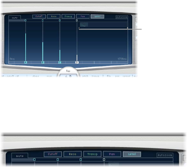
Chapter 2 Delay eects 56
Use the Delay Designer Tap display
The view buttons determine the parameter shown in Delay Designer’s Tap display.
The Toggle bar is shown below the view buttons. You can use it to turn parameters on or o for
each tap.
You can use Delay Designer’s Overview display to zoom and to navigate the Tap display area.
Overview display
Tip: If the Overview display is hidden behind a tap, you can move it to the foreground by
holding down Shift.
Select the parameter shown in the Tap display
mClick one (or more) of the following buttons to select the parameter or parameters shown in the
Tap display.
•Cuto button: Shows the highpass and lowpass lter cuto frequencies of taps.
•Reso(nance) button: Shows the lter resonance value of each tap.
•Transp(ose) button: Shows the pitch transposition of each tap.
•Pan button: Shows the pan parameter of each tap.
•For mono to stereo channels, each tap contains a line showing its pan position.
•For stereo to stereo channels, each tap contains a dot showing its stereo balance. A line
extending outward from the dot indicates the tap’s stereo spread.
•For surround channels, each tap contains a line representing its surround angle. See Use
Delay Designer in surround on page 71.
•Level button: Shows the relative volume level of each tap.
Tip: Press Command-Option to temporarily switch the Tap display to Level view from
another view.
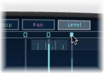
Chapter 2 Delay eects 57
Use Delay Designer’s tap toggle buttons
Each tap has its own toggle button in the Toggle bar. These buttons provide a quick way to
graphically turn parameters on and o. The parameter being toggled is determined by the
current view button selection.
1 Click the view button for the parameter you want to toggle.
2 Click the toggle button of each tap that you want to change:
•Cuto view: Turn the lter on or o.
•Reso view: Switch the lter slope between 6 dB and 12 dB.
•Pitch view: Switch pitch transposition on or o.
•Pan view: Switch between the Flip modes.
•Level view: Mute or unmute the tap.
Note: The rst time you edit a lter or pitch transpose parameter, the lter or pitch transposition
module automatically turns on. After you manually turn o either of these modules, however,
you need to manually switch it back on.
Temporarily switch the mute state of taps
mIn any view, Command-Option-click a toggle button.
When you release the Command and Option keys, the toggle buttons return to their standard
functionality in the active view.
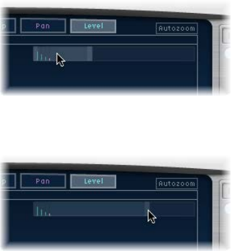
Chapter 2 Delay eects 58
Zoom the Tap display
Do one of the following:
mVertically drag the highlighted section (the bright rectangle) in the Overview display.
mHorizontally drag the highlighted bars—to the left or right of the bright rectangle—in the
Overview display.
Note: The Autozoom button needs to be turned o when you manually zoom in the Overview
display. When you zoom in on a small group of taps, the Overview display continues to
show all taps. The area shown in the Tap display is indicated by the bright rectangle in the
Overview display.
Move to dierent sections of the Tap display
mHorizontally drag the middle of the bright rectangle in the Overview display.
The zoomed view in the Tap display updates as you drag.
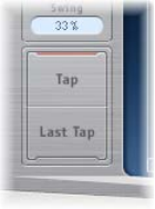
Chapter 2 Delay eects 59
Create taps in Delay Designer
You can create new delay taps in three dierent ways: by using the Tap pads, by creating them in
the Identication bar, or by copying existing taps.
The fastest way to create multiple taps is to use the Tap pads. If you have a specic rhythm in
mind, you might nd it easier to tap out your rhythm on dedicated hardware controller buttons,
instead of using mouse or trackpad clicks. If you have a MIDI controller, you can assign the Tap
pads to buttons on your device. For information about assigning controllers, see the Control
Surfaces Support Help.
After a tap has been created, you can adjust its position, or you can remove it. See Select, move,
and delete taps on page 61.
Taps are assigned letters, based on their order of creation. The rst tap to be created is assigned
as Tap A, the second tap is assigned as Tap B, and so on. Once assigned, each tap is always
identied by the same letter, even when moved in time, and therefore reordered. For example,
if you initially create three taps, they are named Tap A, Tap B, and Tap C. If you then change the
delay time of Tap B so that it precedes Tap A, it is still called Tap B.
The Identication bar shows the letter of each visible tap. The Tap Delay eld of the Tap
parameter bar displays the letter of the currently selected tap or the letter of the tap being
edited when multiple taps are selected (for details, see Select, move, and delete taps on page 61).
Create taps with the Tap pad
1 Click the upper pad (Start).
Note: Whenever you click the Start pad, it automatically erases all existing taps. Because of this
behavior, after you create your initial taps, you will want to create subsequent taps by clicking in
the Identication bar.
The upper pad label changes to Tap, and a red tap recording bar appears in the strip below the
view buttons.
2 To begin recording new taps, click the Tap button.
3 To create new taps, click the Tap button.
These are created at the exact moments in time of each click, adopting the rhythm of your
click pattern.
4 To nish creating taps, click the Last Tap button.
The nal tap is added, ending tap recording, and assigning the last tap as the feedback tap (for
more information about the feedback tap, see Delay Designer master parameters on page 70).
Note: If you do not click the Last Tap button, tap recording automatically stops after 10 seconds
or when the 26th tap is created, whichever comes rst.
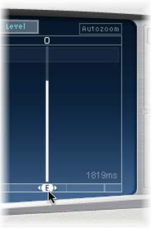
Chapter 2 Delay eects 60
Create a tap in the Identication bar
mClick the position where you want to add a tap.
Copy taps in the Identication bar
mOption-drag a selection of one or more taps to the position where you want to add the tap
or taps.
The delay time of copied taps is set to the drag position.
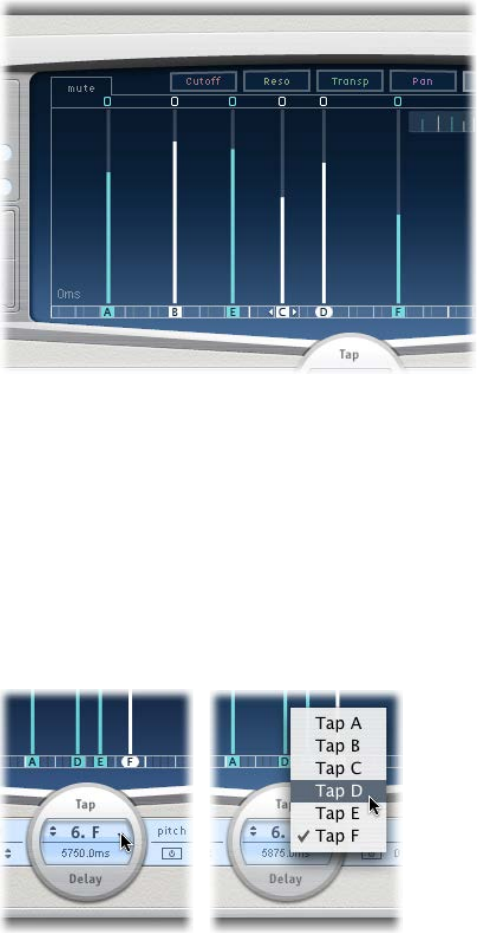
Chapter 2 Delay eects 61
Select, move, and delete taps
There is always at least one selected tap. You can easily distinguish selected taps by color—the
Toggle bar icons and the Identication bar letters of selected taps are white.
You can move a tap backward or forward in time or completely remove it.
Note: When you move a tap, you are actually editing its delay time.
Select a tap
Do one of the following:
mClick a tap in the Tap display.
mClick the tap letter in the Identication bar.
mClick one of the arrows to the left of the Tap name to select the next or previous tap.
mChoose the tap letter from the pop-up menu to the right of the Tap name.
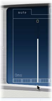
Chapter 2 Delay eects 62
Select multiple taps
Do one of the following:
mTo select multiple taps: Drag across the background of the Tap display.
mTo select multiple nonadjacent taps: Shift-click specic taps in the Tap display.
Move a selected tap in time
mIn the Identication bar, drag a tap to the left to go forward in time, or to the right to go
backward in time.
This method also works when more than one tap is selected.
Note: Editing the Delay Time parameter in the Tap Delay eld of the Tap parameter bar
also moves a tap in time. For more details about the Tap Delay eld and editing taps, see
Delay Designer Tap parameter bar on page 68.
Delete a tap
Do one of the following:
mSelect a tap, then press the Delete key.
mIn the Identication bar, drag a tap letter downward, out of the Tap display.
This method also works when more than one tap is selected.
Delete all selected taps
mControl-click (or right-click) a tap, then choose “Delete tap(s)” from the shortcut menu.
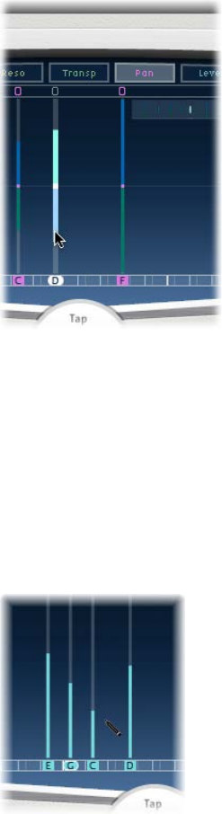
Chapter 2 Delay eects 63
Edit parameters in the Tap display
You can graphically edit any tap parameter that is represented as a vertical line in
Delay Designer’s Tap display. The Tap display is ideal if you want to edit the parameters of one
tap relative to other taps or when you need to edit or align multiple taps simultaneously.
Edit a tap parameter in the Tap display
1 Click the view button of the parameter you want to edit.
2 Vertically drag the bright line of the tap you want to edit (or one of the selected taps, if multiple
taps are selected).
If you selected multiple taps, the values of all selected taps are changed relative to each other.
Note: The method outlined above is slightly dierent for the Filter Cuto and Pan parameters.
See the tasks below.
Set the values of multiple taps
mCommand-drag horizontally and vertically across several taps in the Tap display.
Parameter values change to match the pointer position as you drag across the taps. Command-
dragging across several taps lets you draw value curves, much like using a pencil to create a
curved line on a piece of paper.
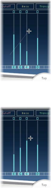
Chapter 2 Delay eects 64
Align the values of several taps
1 Command-click in the Tap display, and drag while holding down the Command key.
A line trails behind the pointer as you drag.
2 Click the appropriate position to mark the end point of the line.
The values of taps that fall between the start and end points are aligned along the line.
Reset the value of a tap
You can use Delay Designer’s Tap display or Tap parameter bar to reset tap parameters to their
default values.
mTo reset a parameter to its default setting in the Tap display: Option-click a tap to reset the selected
parameter to its default setting.
If multiple taps are selected, Option-clicking any tap resets the chosen parameter to its default
value for all selected taps.
mTo reset a parameter to its default setting in the Tap parameter bar: Option-click a parameter value
to reset it to the default setting.
If multiple taps are selected, Option-clicking a parameter of any tap resets all selected taps to the
default value for that parameter.
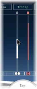
Chapter 2 Delay eects 65
Edit lter cuto in the Tap display
In Cuto view, each tap actually shows two parameters: highpass and lowpass lter
cuto frequency.
mDrag the cuto frequency line—the upper line is lowpass and the lower line is highpass—to
independently adjust lter cuto values. Both cuto frequencies can be adjusted simultaneously
by dragging in the area between them.
When the highpass lter cuto frequency value is lower than that of the lowpass cuto
frequency, only one line is shown. This line represents the frequency band that passes through
the lters—in other words, the lters act as a bandpass lter. In this conguration, the two lters
operate serially, meaning that the tap passes through one lter rst, then the other.
If the highpass lter’s cuto frequency value is above that of the lowpass lter cuto
frequency, the lter switches from serial operation to parallel operation, meaning that the
tap passes through both lters simultaneously. In this case, the space between the two cuto
frequencies represents the frequency band being rejected—in other words, the lters act as a
band-rejection lter.
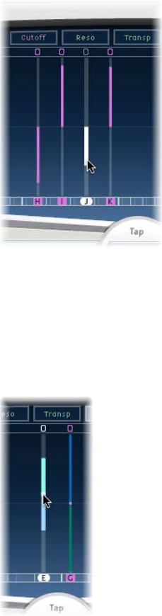
Chapter 2 Delay eects 66
Edit pan in the Tap display
The way the Pan parameter is represented in the Pan view is entirely dependent on the input
channel conguration—mono to stereo, stereo to stereo, or surround.
•In mono input/stereo output congurations, all taps are initially panned to the center.
•In stereo input/stereo output congurations, the Pan parameter adjusts the stereo balance,
not the position of the tap in the stereo eld.
Note: Pan is not available in mono congurations.
mTo edit the pan position in mono input/stereo output congurations: Drag vertically from the center
of the tap in the direction you want to pan the tap or taps.
A white line extends outward from the center in the direction you have dragged, reecting the
pan position of the tap or taps.
Lines above the center position indicate pans to the left, and lines below the center position
denote pans to the right. Left (blue) and right (green) channels are easily identied.
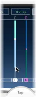
Chapter 2 Delay eects 67
mTo adjust the stereo balance in stereo input/stereo output congurations: Drag the Pan parameter—
which appears as a dot on the tap—up or down the tap to adjust the stereo balance.
By default, stereo spread is set to 100%. To adjust the spread width, drag either side of the dot.
As you do so, the width of the line extending outward from the dot changes. Keep an eye on the
Spread parameter in the Tap parameter bar while you are adjusting.
Note: In Surround congurations, the bright line represents the surround angle. See Use
Delay Designer in surround on page 71.
Edit taps with shortcut menu commands
mControl-click (or right-click) a tap in the Tap display, then choose one of the following commands
from the shortcut menu:
•Copy sound parameters: Copies all parameters (except the delay time) of the selected tap or
taps to the Clipboard.
•Paste sound parameters: Pastes the tap parameters from the Clipboard into the selected tap or
taps. If there are more taps in the Clipboard than are selected in the Tap display, the extra taps
in the Clipboard are ignored.
•Reset sound parameters to default values: Resets all parameters of all selected taps (except the
delay time) to the default values.
•2 x delay time: Doubles the delay time of all selected taps. For example, the delay times of three
taps are set as follows: Tap A = 250 ms, Tap B = 500 ms, and Tap C = 750 ms. If you select these
three taps and choose “2 x delay time,” the taps are changed as follows: Tap A = 500 ms, Tap B
= 1000 ms, and Tap C = 1500 ms. In other words, a rhythmic delay pattern unfolds half as fast.
(In musical terms, it is played in half time.)
•1/2 x delay time: Halves the delay time of all selected taps. Using the example above, choosing
“1/2 x delay time” changes the taps as follows: Tap A = 125 ms, Tap B = 250 ms, and Tap C =
375 ms. In other words, a rhythmic delay pattern unfolds twice as fast. (In musical terms, it is
played in double time.)
•Delete tap(s): Deletes all selected taps.
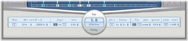
Chapter 2 Delay eects 68
Delay Designer Tap parameter bar
The Tap parameter bar provides access to all parameters of the selected tap. It also shows several
parameters that are not available in the Tap display, such as Transpose and Flip.
Editing the parameters of a single, selected tap is fast and precise because all parameters are
visible, with no need to switch display views or estimate values with vertical lines. If you choose
multiple taps in the Tap display, the values of all selected taps are changed relative to each other.
Option-click a parameter value to reset it to the default setting. If multiple taps are selected,
Option-clicking a parameter of any tap resets all selected taps to the default value for
that parameter.
Tap parameter bar controls
•Filter On/O button: Turns the highpass and lowpass lters on or o (for the selected tap).
•HP-Cuto-LP elds: Drag to set the cuto frequencies (in Hz) for the highpass and
lowpass lters.
•Slope buttons: Determine the steepness of the highpass and lowpass lter slope. Click the
6 dB button for a gentler lter slope, or click the 12 dB button for a steeper, more pronounced
ltering eect.
Note: You cannot set the slope of the highpass and lowpass lters independently.
•Reso(nance) eld: Drag to set the amount of lter resonance for both lters.
•Tap Delay elds: Show the number and name of the selected tap in the upper section and the
delay time in the lower section.
•Pitch On/O button: Click to turn pitch transposition on or o (for the selected tap).
•Transp(ose) elds: The left eld transposes pitch in semitones. The right eld ne-tunes each
semitone step in cents (1/100th of a semitone).
•Flip buttons: Swap the left and right side of the stereo or surround image. Clicking these
buttons reverses the tap position from left to right, or vice versa. For example, if a tap is set to
55% left, clicking the ip button swaps it to 55% right.
•Pan eld: Drag to set pan position for mono signals, stereo balance for stereo signals, and
surround angle when used in surround congurations.
•Pan displays a percentage between 100% (full left) and −100% (full right), which
represents the pan position or balance of the tap. A value of 0% represents the center
panorama position.
•When used in surround, a surround panner replaces the percentage representation. See Use
Delay Designer in surround on page 71.
•Spread eld: Drag to set the width of the stereo spread for the selected tap (in stereo-to-stereo
or stereo-to-surround instances).
•Mute button: Click to mute (silence) or unmute the selected tap.
•Level eld: Drag to set the output level for the selected tap.
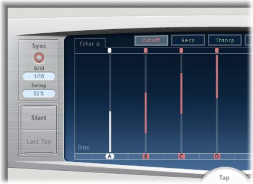
Chapter 2 Delay eects 69
Delay Designer sync mode
Delay Designer can either synchronize to the project tempo or can run independently. When you
are in synchronized mode (sync mode), taps snap to a grid of musically relevant positions, based
on note durations. You can also set a Swing value in sync mode, which varies the precise timing
of the grid, resulting in a laid-back, less robotic feel for each tap. When you are not in sync mode,
taps don’t snap to a grid, nor can you apply the Swing value.
When sync mode is on, a grid that matches the chosen Grid parameter value is shown in
the Identication bar. All taps are moved toward the closest delay time value on the grid.
Subsequently created or moved taps are snapped to positions on the grid.
When you save a Delay Designer setting, the sync mode status, Grid, grid position of each tap,
and Swing values are all saved. This ensures that a setting loaded into a project with a dierent
tempo to that of the project the setting was created in retains the relative positions, and rhythm,
of all taps—at the new tempo.
Note: Delay Designer has a maximum delay time of 10 seconds. This means that if you load a
setting into a project with a slower tempo (than the setting’s tempo), some taps may fall outside
the 10 second limit. In such cases, these taps do not play but are retained as part of the setting.
Sync parameters
•Sync button: Turns synchronized mode on or o.
•Grid pop-up menu: Choose a grid resolution from several musical note durations. The grid
resolution, along with the project tempo, determines the length of each grid increment.
As you change grid resolutions, the increments shown in the Identication bar change
accordingly. This also determines a step limitation for all taps.
For example, imagine a project with a tempo of 120 bpm. The Grid pop-up menu value is set
to 1/16 notes. At this tempo and grid resolution, each grid increment is 125 milliseconds (ms)
apart. If Tap A is currently set to 380 ms, turning on sync mode shifts Tap A to 375 ms. If you try
to move Tap A forward in time, it snaps to 500 ms, 625 ms, 750 ms, and so on. At a resolution
of 1/8 notes, the steps are 250 milliseconds apart, so Tap A automatically snaps to the nearest
division (500 ms) and could be moved to 750 ms, 1000 ms, 1250 ms, and so on.
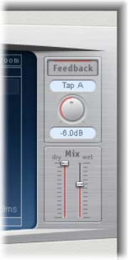
Chapter 2 Delay eects 70
•Swing eld: Drag to determine how close to the absolute grid position every second grid
increment will be.
•A setting of 50% means that every grid increment has the same value.
•Settings below 50% result in every second increment being shorter in time.
•Settings above 50% result in every second grid increment being longer in time.
Tip: Use subtle grid position variations of every second increment (values between 45% and
55%) to create a less rigid rhythmic feel. High Swing values are unsubtle because they place
every second increment directly beside the subsequent increment. Make use of higher values
to create interesting and intricate double rhythms with some taps, while retaining the grid to
lock other taps into more rigid synchronization with the project tempo.
Delay Designer master parameters
The Master section incorporates two global functions: delay feedback and dry/wet mix.
In simple delays, the only way for the delay to repeat is to use feedback. Because Delay Designer
oers 26 taps, you can use these taps to create repeats, rather than requiring discrete feedback
controls for each tap.
Delay Designer’s global Feedback parameter does, however, enable you to send the output of
one user-dened tap back through the eect input, to create a self-sustaining rhythm or pattern.
This tap is known as the feedback tap.
Master parameters
•Feedback button: Turn the feedback tap on or o.
•Feedback Tap pop-up menu: Choose a tap as the feedback tap.
•Feedback Level knob: Rotate to set the feedback tap output level (before it is routed back into
Delay Designer’s input).
•A value of 0% equals no feedback.
•A value of 100% sends the feedback tap back into Delay Designer’s input at full volume.
Note: If Feedback is enabled and you begin creating taps with the Tap pads, Feedback
is automatically turned o. When you stop creating taps with the Tap pads, Feedback is
automatically re-enabled.
•Mix sliders: Drag to independently set the levels of the dry input signal and the post-
processing wet signal.
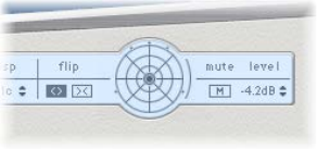
Chapter 2 Delay eects 71
Use Delay Designer in surround
Delay Designer is optimized for use in surround congurations. With 26 taps that can be
positioned in the surround eld, you can create interesting rhythmic and spatial eects.
Note: Delay Designer generates separate automation data for stereo pan and surround pan
operations. This means that when you use it in surround channels, it does not react to existing
stereo pan automation data, and vice versa.
Delay Designer always processes each input channel independently.
•In a mono/stereo input and surround output conguration, Delay Designer processes the two
stereo channels independently, and the surround panner lets you place each delay around the
surround eld.
•In a surround input and surround output conguration, Delay Designer processes each
surround channel independently and the surround panner lets you adjust the surround
balance of each tap in the surround eld.
When you use Delay Designer in any surround conguration, the Pan parameter on the Tap
parameter bar is replaced with a surround panner, which lets you determine the surround
position of each tap.
Note: In the Tap display’s Pan view, you can adjust only the angle of taps. You must use the
surround panner on the Tap Parameter bar to adjust diversity.
Adjust surround parameters
mTo adjust diversity: Command-drag.
mTo adjust the angle: Command-Option-drag.
mTo reset the angle and diversity: Option-click the blue dot.
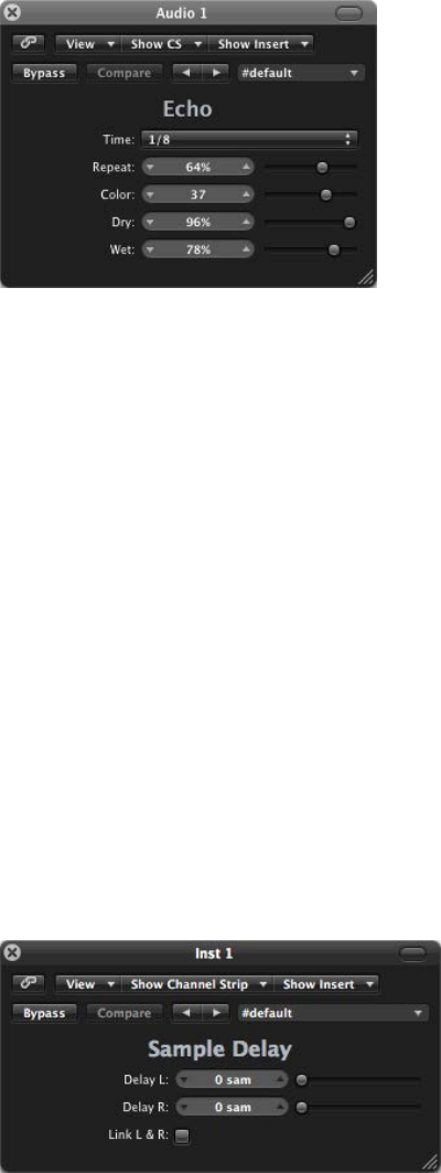
Chapter 2 Delay eects 72
Echo
This simple echo eect always synchronizes the delay time to the project tempo, enabling you to
quickly create echo eects that run in time with your composition.
Echo parameters
•Time pop-up menu: Choose the grid resolution of the delay time in musical note durations,
based on the project tempo.
•“T” values represent triplets.
•“.” values represent dotted notes.
•Repeat slider and eld: Drag to determine how often the delay eect is repeated.
•Color slider and eld: Drag to set the harmonic content (color) of the delay signal.
•Dry and Wet sliders and elds: Drag to set the amount of original and eect signal.
Sample Delay
Sample Delay is more a utility than an eect—you can use it to delay a channel by single
sample values.
When used in conjunction with the phase inversion capabilities of the Gain eect, Sample Delay
is useful for correcting timing problems that may occur with multichannel microphones. It can
also be used creatively to emulate stereo microphone channel separation.
Every sample at a frequency of 44.1 kHz is equivalent to the time taken for a sound wave to travel
7.76 millimeters. If you delay one channel of a stereo microphone by 13 samples, this emulates an
acoustic (microphone) separation of 10 centimeters.
Sample Delay parameters
•Delay slider and eld (L and R in stereo version): Drag to set the number of samples that the
incoming signal is delayed by.
•Link L & R button (only in stereo version): Turn on to make sure that the number of samples is
identical for both channels. Adjusting one channel value adjusts the other.
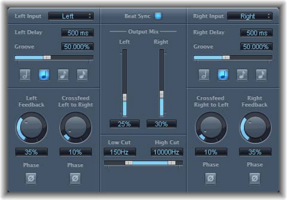
Chapter 2 Delay eects 73
Stereo Delay
Stereo Delay lets you set the Delay, Feedback, and Mix parameters separately for the left and
right channels. The Crossfeed knob (for each stereo side) sets the feedback intensity level of each
signal being routed to the opposite stereo side. You can use Stereo Delay on mono tracks or
busses when you want to create independent delays for the two stereo sides.
Note: If you use Stereo Delay on mono channel strips, the track or bus will have two channels
from the point of insertion—all Insert slots after the chosen slot will be stereo.
The parameters for the left and right delays are identical. The descriptions below describe the
left channel—the right channel parameter title is provided in parentheses, if named dierently.
Parameters common to both channels are described after the channel parameters.
Channel parameters
•Left (Right) Input pop-up menu: Choose the input signal for the two stereo sides. Options
include O, Left, Right, L + R, and L − R.
•Left (Right) Delay eld: Drag to set the delay time in milliseconds. (The parameter is dimmed
when you synchronize the delay time with the project tempo.)
•Groove slider and eld: Drag to determine the proximity of every second delay repeat to the
absolute grid position—in other words, how close every second delay repeat is.
•Note buttons: Click to set the grid resolution for the delay time. These are shown as note
durations. (These are dimmed when the delay time is not synchronized with the project
tempo.)
•Left (Right) Feedback knob and eld: Rotate to set the amount of feedback for the left and right
delay signals.
•Crossfeed Left to Right (Crossfeed Right to Left) knob and eld: Rotate to transfer the feedback
signal of the left channel to the right channel, and vice versa.
•Feedback Phase button: Click to invert the phase of the corresponding channel’s
feedback signal.
•Crossfeed Phase button: Click to invert the phase of the crossfed feedback signals.
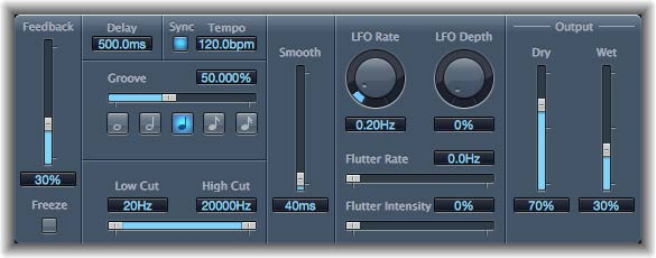
Chapter 2 Delay eects 74
Common parameters
•Beat Sync button: Turn on to synchronize delay repeats to the project tempo.
•Output Mix (Left and Right) sliders and elds: Drag to independently control the level of the left
and right channel signals.
•Low Cut and High Cut sliders and elds: Drag to cut frequencies below the Low Cut value and
above the High Cut value from the source signal.
Tape Delay
Tape Delay simulates the sound of vintage tape echo machines. It can run at a free rate or can
be synchronized with the project tempo. The eect is equipped with a highpass and lowpass
lter in the feedback loop, making it easy to create authentic dub echo eects. Tape Delay also
includes an LFO for delay time modulation. This can be used to produce chorus eects, even on
long delays.
Tape Delay parameters
•Feedback slider: Drag to set the amount of delayed and ltered signal that is routed back to
the input. Set to the lowest possible value to generate a single echo. Set to 100% to endlessly
repeat the signal. The levels of the original signal and taps (echo repeats) tend to accumulate
and may cause distortion. Use the internal tape saturation circuit to make these overdriven
signals sound pleasant.
•Freeze button: Captures the current delay repeats and sustains them until Freeze is turned o.
•Delay eld: Drag to set the delay time in milliseconds. (This parameter is dimmed when you
synchronize the delay time to the project tempo.)
•Sync button: Click to synchronize delay repeats with the project tempo (including tempo
changes).
•Tempo eld: Drag to set the delay time in beats per minute. (This parameter is dimmed when
you synchronize the delay time to the project tempo.)
•Groove slider and eld: Drag to determine the proximity of every second delay repeat to the
absolute grid position—in other words, how close every second delay repeat is. A Groove
setting of 50% means that every delay has the same delay time. Settings below 50% result in
every second delay being played earlier in time. Settings above 50% result in every second
delay being played later in time. When you want to create dotted note values, move the
Groove slider all the way to the right (to 75%). For triplets, select the 33.33% setting.
•Note buttons: Set the grid resolution for the delay time. These are shown as note durations.
Chapter 2 Delay eects 75
•Low Cut and High Cut sliders and elds: Drag to cut frequencies below the Low Cut value and
above the High Cut value from the source signal. You can shape the sound of taps (delay
repeats) with the highpass and lowpass lters. The lters are located in the feedback circuit,
which means that the ltering eect increases in intensity with each delay repeat. If you want
an increasingly muddy and confused tone, move the High Cut slider toward the left. For ever
thinner echoes, move the Low Cut slider toward the right. If you can’t hear the eect, check
the Dry and Wet controls and the lter settings.
•Smooth slider and eld: Drag to even out the LFO and utter eect.
•LFO Rate knob and eld: Rotate to set the speed of the LFO.
•LFO Depth knob and eld: Rotate to set the amount of LFO modulation. A value of 0 turns delay
modulation o.
•Flutter Rate and Intensity sliders and elds: Simulate the speed irregularities of the tape
transports used in analog tape delay units.
•Flutter Rate: Drag to set the speed variation.
•Flutter Intensity: Drag to determine the intensity of the eect.
•Dry and Wet sliders and elds: Drag to independently control the amount of original and
eect signal.
•Distortion Level slider and eld (Extended Parameters area): Drag to set the level of the distorted
(tape saturation) signal.

76
Distortion eects overview
Distortion eects simulate the distortion created by vacuum tubes, transistors, or digital circuits.
Vacuum tubes were used in audio ampliers before the development of digital audio technology.
They are still used in musical instrument ampliers today. When overdriven, tubes produce a
musically pleasing distortion that has become a familiar part of the sound of rock and pop music.
Analog tube distortion adds a distinctive warmth and bite to the signal.
There are also distortion eects that intentionally cause clipping and digital distortion of the
signal. These can be used to modify vocal, music, and other tracks to produce an intense,
unnatural tone, or to create sound eects.
Distortion eects include parameters for tone, which let you shape the way the distortion alters
the signal (often as a frequency-based lter), and for gain, which let you control how much the
distortion alters the output level of the signal.
WARNING: When set to high output levels, distortion eects can damage your hearing—and
your speakers. When you adjust eect settings, it is recommended that you lower the output
level of the track, and raise the level gradually when you are nished.
Distortion eects 3
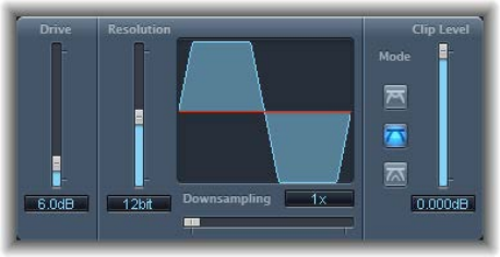
Chapter 3 Distortion eects 77
Bitcrusher
Bitcrusher is a low-resolution digital distortion eect. You can use it to emulate the sound of early
digital audio devices, to create articial aliasing by dividing the sample rate, or to distort signals
until they are unrecognizable.
Bitcrusher parameters
•Drive slider and eld: Drag to set the amount of gain applied to the input signal (in decibels).
Note: Raising the Drive level tends to increase the amount of clipping at the output of the
Bitcrusher as well.
•Resolution slider and eld: Drag to set the bit rate (between 1 and 24 bits). This alters the
calculation precision of the process. Lowering the value increases the number of sampling
errors, generating more distortion. At extremely low bit rates, the amount of distortion can be
greater than the level of the usable signal.
•Waveform display: Shows the impact of parameters on the distortion process.
•Downsampling slider and eld: Drag to reduce the sample rate. A value of 1x has no eect on
the signal, a value of 2x halves the sample rate, and a value of 10x reduces the sample rate to
one-tenth of the original. (For example, if you set Downsampling to 10x, a 44.1 kHz signal is
sampled at just 4.41 kHz.)
Note: Downsampling has no impact on the playback speed or pitch of the signal.
•Mode buttons: Set the distortion mode to Folded, Cut, or Displaced. Signal peaks that exceed
the clip level are processed.
Note: The Clip Level parameter has a signicant impact on the behavior of all three modes.
This is reected in the Waveform display, so try each mode button and adjust the Clip Level
slider to get a feel for how this works.
•Folded button: The center portion of the signal is halved in level above the threshold,
resulting in a softer distortion. The start and end levels of the clipped signal are unchanged.
•Cut button: Causes abrupt distortion when the clipping threshold is exceeded. Clipping that
occurs in most digital systems is closest to Cut mode.
•Displaced button: The start, mid, and end levels of the signal (above the threshold) are oset,
resulting in less severe distortion as signal levels cross the threshold. The center portion of
the clipped signal is also softer than in Cut mode.
•Clip Level slider and eld: Drag to set the point (below the clipping threshold of the channel) at
which the signal starts clipping.
•Mix slider and eld (Extended Parameters area): Drag to set the balance between dry (original)
and wet (eect) signals.
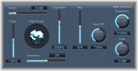
Chapter 3 Distortion eects 78
Clip Distortion
Clip Distortion is a nonlinear distortion eect that produces unpredictable spectra. It can
simulate warm, overdriven tube sounds and can also generate heavy distortions.
Clip Distortion has an unusual combination of serially connected lters. The incoming signal
is amplied by the Drive value, passes through a highpass lter, then is subjected to nonlinear
distortion. Following the distortion, the signal passes through a lowpass lter. The eect signal is
then recombined with the original signal and this mixed signal is sent through a further lowpass
lter. All three lters have a slope of 6 dB/octave.
This unique combination of lters allows for gaps in the frequency spectra that can sound good
with this sort of nonlinear distortion.
Clip Distortion parameters
•Drive slider and eld: Drag to set the amount of gain applied to the input signal. After being
amplied by the Drive value, the signal passes through a highpass lter.
•Tone slider and eld: Drag to set the cuto frequency (in hertz) of the highpass lter.
•Clip Circuit display: Shows the impact of all parameters, with the exception of the High Shelving
lter parameters.
•Symmetry slider and eld: Drag to set the amount of nonlinear (asymmetrical) distortion
applied to the signal.
•Clip Filter slider and eld: Drag to set the cuto frequency (in hertz) of the rst lowpass lter.
•Mix slider and eld: Drag to set the ratio between the eect (wet) signal and original (dry)
signals, following the Clip Filter.
•Sum LPF knob and eld: Drag to set the cuto frequency (in hertz) of the lowpass lter. This
processes the mixed signal.
•(High Shelving) Frequency knob and eld: Rotate to set the frequency (in hertz) of the high
shelving lter. If you set the High Shelving Frequency to around 12 kHz, you can use it like the
treble control on a mixer channel strip or a stereo hi- amplier. Unlike these types of treble
controls, however, you can boost or cut the signal by up to ±30 dB with the Gain parameter.
•(High Shelving) Gain knob and eld: Rotate to set the amount of gain applied to the output of
signals above the high shelving lter frequency.
•Input Gain eld and slider (Extended Parameters area): Drag to set the amount of gain applied to
the input signal.
•Output Gain eld and slider (Extended Parameters area): Drag to set the amount of gain applied
to the output signal.
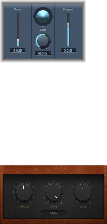
Chapter 3 Distortion eects 79
Distortion eect
The Distortion eect simulates the low delity distortion generated by a bipolar transistor. You
can use it to simulate playing a musical instrument through a highly overdriven amplier or to
create unique distorted sounds.
Distortion parameters
•Drive slider and eld: Drag to set the amount of saturation applied to the signal.
•Display: Shows the impact of parameters on the signal.
•Tone knob and eld: Rotate to set the frequency for the high cut lter. Filtering the harmonically
rich distorted signal produces a softer tone.
•Output slider and eld: Drag to set the output level. This enables you to compensate for
increases in loudness caused by adding distortion.
•Level Compensation checkbox (Extended parameter): Turn on to reference the overall processing
of the signal to 0 dB, making the output louder.
Distortion II
Distortion II emulates the distortion circuit of a Hammond B3 organ. You can use it on musical
instruments to recreate this classic eect or can use it creatively when designing new sounds.
Distortion II parameters
•PreGain knob: Rotate to set the amount of gain applied to the input signal.
•Drive knob: Rotate to set the amount of saturation applied to the signal.
•Tone knob: Rotate to set the frequency of the highpass lter. Filtering the harmonically rich
distorted signal produces a softer tone.
•Type pop-up menu: Choose the type of distortion.
•Growl: Emulates a two-stage tube amplier similar to the type found in a Leslie 122 speaker
cabinet, which is often used with the Hammond B3 organ.
•Bity: Emulates the sound of a bluesy (overdriven) guitar amp.
•Nasty: Produces hard distortion, suitable for creating very aggressive sounds.
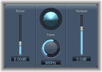
Chapter 3 Distortion eects 80
Overdrive
Overdrive emulates the distortion produced by a eld eect transistor (FET), commonly used
in solid-state musical instrument ampliers and hardware eects devices. When saturated, FETs
generate a warmer-sounding distortion than bipolar transistors, such as those emulated by the
Distortion eect.
Overdrive parameters
•Drive slider and eld: Drag to set the saturation amount for the simulated transistor.
•Display: Shows the impact of parameters on the signal.
•Tone knob and eld: Rotate to set the frequency for the high cut lter. Filtering the harmonically
rich distorted signal produces a softer tone.
•Output slider and eld: Drag to set the output level. This enables you to compensate for
increases in loudness caused by using Overdrive.
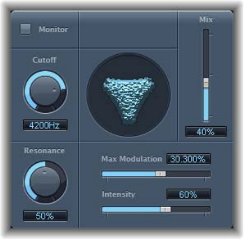
Chapter 3 Distortion eects 81
Phase Distortion
The Phase Distortion eect is based on a modulated delay line, similar to a chorus or anger
eect (see Modulation eects overview on page 19 9). Unlike these eects, however, the delay
time is not modulated by a low frequency oscillator (LFO) but rather by a lowpass-ltered
version of the input signal itself, using an internal sidechain. This means that the incoming signal
modulates its own phase position.
The input signal only passes the delay line and is not aected by any other process. The Mix
parameter blends the eect signal with the original signal.
Phase Distortion parameters
•Monitor button: Turn on to hear the input signal in isolation. Turn o to hear the mixed signal.
•Cuto knob and eld: Rotate to set the (center) cuto frequency of the lowpass lter.
•Resonance knob and eld: Rotate to emphasize frequencies surrounding the cuto frequency.
•Display: Shows the impact of parameters on the signal.
•Mix slider and eld: Drag to set the percentage of the eect signal mixed with the
original signal.
•Max Modulation slider and eld: Drag to set the maximum delay time.
•Intensity slider and eld: Drag to set the amount of modulation applied to the signal.
•Phase Reverse checkbox (Extended Parameters area): Select to reduce the delay time on the right
channel when input signals that exceed the cuto frequency are received. Available only for
stereo instances of the Phase Distortion eect.
82
Dynamics processors overview
Dynamics processors control the perceived loudness of your audio, add focus and punch to
tracks and projects, and optimize the sound for playback in dierent situations.
The dynamic range of an audio signal is the range between the softest and loudest parts of the
signal—technically, between the lowest and highest amplitudes. Dynamics processors enable
you to adjust the dynamic range of individual audio les, tracks, or an overall project. This can be
to increase the perceived loudness or to highlight the most important sounds, while ensuring
that softer sounds are not lost in the mix.
There are four types of dynamics processors. These are each used for dierent audio
processing tasks.
•Compressors: Downward compressors behave like an automatic volume control, lowering the
volume whenever it rises above a certain level, called the threshold.
By reducing the highest parts of the signal, called peaks, a compressor raises the overall level
of the signal, increasing the perceived volume. This gives the signal more focus by making
the louder (foreground) parts stand out, while keeping the softer background parts from
becoming inaudible. Compression also tends to make sounds tighter or punchier because
transients are emphasized, depending on attack and release settings, and because the
maximum volume is reached more swiftly.
In addition, compression can make a project sound better when played back in dierent audio
environments. For example, the speakers of a television or in a car typically have a narrower
dynamic range than the sound system in a cinema. Compressing the overall mix can help
make the sound fuller and clearer in lower-delity playback situations.
Compressors are typically used on vocal tracks to make the singing prominent in an overall
mix. They are also commonly used on music and sound eect tracks, but they are rarely used
on ambience tracks.
Some compressors—multiband compressors—can divide the incoming signal into dierent
frequency bands and apply dierent compression settings to each band. This helps to achieve
the maximum level without introducing compression artifacts. Multiband compression is
typically used on an overall mix.
•Expanders: Expanders are similar to compressors, except that they raise, rather than lower, the
signal when it exceeds the threshold. Expanders are used to add life to audio signals.
•Limiters: Limiters (also called peak limiters) work in a similar way to compressors in that they
reduce the audio signal when it exceeds a set threshold. The dierence is that whereas a
compressor gradually lowers signal levels that exceed the threshold, a limiter quickly reduces
any signal that is louder than the threshold to the threshold level. The main use of a limiter is
to prevent clipping while preserving the maximum overall signal level.
Dynamics processors 4
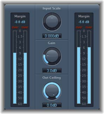
Chapter 4 Dynamics processors 83
•Noise gates: Noise gates alter the signal in a way that is opposite to that used by compressors
or limiters. Whereas a compressor lowers the level when the signal is louder than the
threshold, a noise gate lowers the signal level whenever it falls below the threshold. Louder
sounds pass through unchanged, but softer sounds, such as ambient noise or the decay of a
sustained instrument, are cut o. Noise gates are often used to eliminate low-level noise or
hum from an audio signal.
Adaptive Limiter
Adaptive Limiter is a versatile tool for controlling the perceived loudness of sounds. It works by
rounding and smoothing peaks in the signal, producing an eect similar to an analog amplier
being driven hard. Like an amplier, it can slightly color the sound of the signal. You can use
Adaptive Limiter to achieve maximum gain, without introducing unwanted distortion and
clipping, which can occur when the signal exceeds 0 dBFS.
Adaptive Limiter is typically used on the nal mix, where it can be placed after a compressor,
such as Multipressor, and before a nal gain control, resulting in a mix of maximum loudness.
Adaptive Limiter can produce a louder-sounding mix than can be achieved by normalizing
the signal.
Note: Using Adaptive Limiter adds latency when the Lookahead parameter is active. The eect
is typically used for mixing and mastering previously recorded tracks, not while recording. You
should bypass Adaptive Limiter while recording.
Adaptive Limiter parameters
•Input meters: Show input levels in real time. The Margin eld shows the highest input level. You
can reset the Margin eld by clicking it.
•Input Scale knob and eld: Rotate to scale the input level. Scaling is useful for handling very
high-level or low-level input signals. It “squeezes” the higher and lower signal levels into a
range that allows the Gain knob to work eectively. Avoid input levels above 0 dBFS, which
can result in unwanted distortion.
•Gain knob and eld: Rotate to set the amount of gain after input scaling.
•Out Ceiling knob and eld: Rotate to set the maximum output level, or ceiling. The signal will
not rise above this.
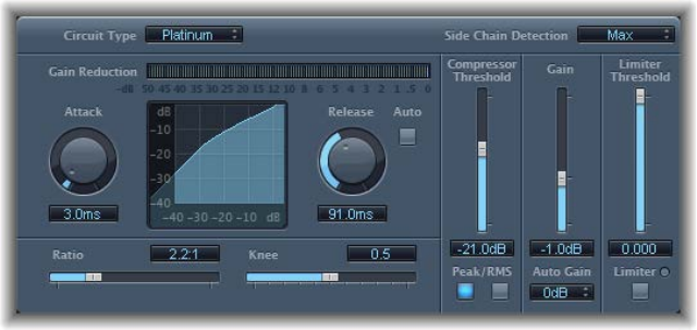
Chapter 4 Dynamics processors 84
•Output meters: Show output levels, enabling you to see the results of the limiting process. The
Margin eld shows the highest output level. You can reset the Margin eld by clicking it.
•Mode buttons (Extended Parameters area): Click to choose the type of peak smoothing:
•OptFit: Limiting follows a linear curve, which allows signal peaks above 0 dB.
•NoOver: Avoids distortion artifacts from the output hardware by ensuring that the signal
does not exceed 0 dB.
•Lookahead eld and slider (Extended Parameters area): Drag to adjust the playback buer size
(how far in the future the le is analyzed for peaks).
•Remove DC checkbox (Extended Parameters area): Select to activate a highpass lter that
removes direct current (DC) from the signal. DC can be introduced by lower-quality
audio hardware.
•Inter Sample Peak Detection checkbox (Extended Parameters area): Select to detect inter-sample
peaks in the signal.
Compressor
Compressor overview
Compressor is designed to emulate the sound and response of a professional-level analog
(hardware) compressor. It tightens up your audio by reducing sounds that exceed a certain
threshold level, smoothing out the dynamics and increasing the overall volume—the perceived
loudness. Compression helps bring the key parts of a track or mix into focus, while preventing
softer parts from becoming inaudible. It is probably the most versatile and widely used sound-
shaping tool in mixing, next to EQ.
You can use Compressor with individual tracks, including vocal, instrumental, and eects tracks,
as well as on the overall mix. Usually you insert the Compressor directly into a channel strip.
Chapter 4 Dynamics processors 85
Compressor parameters
•Circuit Type pop-up menu: Choose the type of circuit emulated by Compressor. The choices are
Platinum, Studio or Vintage VCA or FET, and Vintage Opto.
•Side Chain Detection pop-up menu: Choose the signal type to exceed or fall below the
threshold. Max uses the maximum level of each side-chained signal. Sum uses the summed
level of all side-chained signals.
•If either of the stereo channels exceeds or falls below the threshold, both channels
are compressed.
•If Sum is chosen, the combined level of both channels must exceed the threshold before
compression occurs.
•Gain Reduction meter: Shows the amount of compression in real time.
•Attack knob and eld: Rotate to set the time it takes for Compressor to react when the signal
exceeds the threshold.
•Compression curve display: Shows the compression curve created by the combination of Ratio
and Knee parameter values. The input (level) is shown on the x-axis and output (level) on the
y-axis.
•Release knob and eld: Rotate to set the time it takes for Compressor to stop reducing the
signal after the signal level falls below the threshold.
•Auto button: Turn on to make the release time dynamically adjust to the audio material.
•Ratio slider and eld: Drag to set the compression ratio—the ratio of signal reduction when the
threshold is exceeded.
•Knee slider and eld: Drag to set the strength of compression at levels close to the threshold.
Lower values result in more severe/immediate compression (hard knee). Higher values result in
gentler compression (soft knee).
•Compressor Threshold slider and eld: Drag to set the threshold level—signals above this
threshold value are reduced in level.
•Peak/RMS buttons: Click to determine if signal analysis uses the Peak or RMS method when
using the Platinum circuit type.
•Gain slider and eld: Drag to set the amount of gain applied to the output signal.
•Auto Gain pop-up menu: Choose a value to compensate for volume reductions caused by
compression. The choices are O, 0 dB, and −12 dB.
•Limiter Threshold slider and eld: Drag to set the threshold level for the limiter.
•Limiter button: Turns the integrated limiter on or o.
•Output Distortion pop-up menu (Extended Parameters area): Choose whether to apply clipping
above 0 dB, and the type of clipping. The choices are O, Soft, Hard, and Clip.
•Activity pop-up menu (Extended Parameters area): Turns the side chain on or o.
•Mode pop-up menu (Extended Parameters area): Choose the type of lter used for the side
chain. The choices are LP (lowpass), BP (bandpass), HP (highpass), ParEQ (parametric), and HS
(high shelving).
•Frequency slider and eld (Extended Parameters area): Drag to set the center frequency for the
side-chain lter.
•Q slider and eld (Extended Parameters area): Drag to set the width of the frequency band
aected by the side-chain lter.
•Gain slider and eld (Extended Parameters area): Drag to set the amount of gain applied to the
side-chain signal.
•Mix slider and eld (Extended Parameters area): Drag to set the balance between dry (source)
and wet (eect) signals.
Chapter 4 Dynamics processors 86
Use Compressor
The following explains how to eectively use the main Compressor parameters.
Compressor Threshold and Ratio
The most important Compressor parameters are Threshold and Ratio. The Threshold parameter
sets the oor level in decibels. Signals that exceed this level are reduced by the amount set as
the Ratio.
The Ratio parameter is a percentage of the overall level; the more the signal exceeds the
threshold, the more it is reduced. A ratio of 4:1 means that increasing the input by 4 dB results in
an increase of the output by 1 dB, if above the threshold.
For example, with the Threshold set at −20 dB and the Ratio set to 4:1, a −16 dB peak in the
signal (4 dB louder than the threshold) is reduced by 3 dB, resulting in an output level of −19 dB.
Compressor envelope times
The Attack and Release parameters shape the dynamic response of Compressor. The Attack
parameter determines the time it takes after the signal exceeds the threshold level before
Compressor starts reducing the signal.
Many sounds, including voices and musical instruments, rely on the initial attack phase to dene
the core timbre and characteristic of the sound. When compressing these types of sounds, you
should set higher Attack values to ensure that the attack transients of the source signal aren’t
lost or altered.
When attempting to maximize the level of an overall mix, it is best to set the Attack parameter to
a lower value, because higher values often result in no, or minimal, compression.
The Release parameter determines how quickly the signal is restored to its original level after it
falls below the threshold level. Set a higher Release value to smooth out dynamic dierences in
the signal. Set lower Release values if you want to emphasize dynamic dierences.
Important: The results of your settings for the Attack and Release parameters depend not only
on the type of source material but on the compression ratio and threshold settings.
Compressor Knee
The Knee parameter determines whether the signal is slightly, or severely, compressed as it
approaches the threshold level.
Setting a Knee value close to 0 (zero) results in no compression of signal levels that fall just
below the threshold, while levels at the threshold are compressed by the full Ratio amount. This
is known as hard knee compression, which can cause abrupt and often unwanted transitions as
the signal reaches the threshold.
Increasing the Knee parameter value increases the amount of compression as the signal
approaches the threshold, creating a smoother transition. This is called soft knee compression.
Chapter 4 Dynamics processors 87
Other Compressor parameters
As Compressor reduces levels, the overall volume at its output is typically lower than the input
signal. You can adjust the output level with the Gain slider.
You can also use the Auto Gain parameter to compensate for the level reduction caused by
compression (choose either −12 dB or 0 dB).
When you use the Platinum circuit type, Compressor can analyze the signal using one of two
methods: Peak or root mean square (RMS). While Peak is technically more accurate, RMS provides
a better indication of how people perceive the signal loudness.
Note: If you turn on Auto Gain and RMS simultaneously, the signal may become oversaturated.
If you hear any distortion, turn o Auto Gain and adjust the Gain slider until the distortion
is inaudible.
Use a side chain with Compressor
Use of a side chain with a compressor is common. The dynamics (level changes) of another
channel strip is used as a control source for compression. For example, the dynamics of a drum
groove can be used to rhythmically change the compression, and therefore dynamics, of a
guitar part.
The side-chain signal is used only as a detector or trigger in this situation. The side-chain source
is used to control the compressor, but the audio of the side-chain signal is not actually routed
through the compressor.
1 Insert Compressor into a channel strip.
2 In the Compressor plug-in window header, choose the channel strip that carries the desired
signal (side-chain source) from the Side Chain pop-up menu.
3 Choose the desired analysis method (Max or Sum) from the Side Chain Detection pop-up menu.
4 Adjust Compressor parameters.
DeEsser
DeEsser is a frequency-specic compressor, designed to compress a particular frequency band
within a complex audio signal. It is used to eliminate hiss (also called sibilance) from the signal.
The advantage of using DeEsser rather than an EQ to cut high frequencies is that it compresses
the signal dynamically, rather than statically. This prevents the sound from becoming darker
when no sibilance is present in the signal. DeEsser has extremely fast attack and release times.
When using DeEsser, you can set the frequency range being compressed (the Suppressor
frequency) independently of the frequency range being analyzed (the Detector frequency). The
two ranges can be compared in DeEsser’s Detector and Suppressor frequency range displays. The
Suppressor frequency range is reduced in level for as long as the Detector frequency threshold
is exceeded.
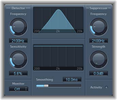
Chapter 4 Dynamics processors 88
DeEsser does not use a frequency-dividing network—a crossover utilizing lowpass and highpass
lters. Rather, it isolates and subtracts the frequency band, resulting in no alteration of the
phase curve.
The Detector parameters are on the left side of DeEsser’s interface, and the Suppressor
parameters are on the right. The center section includes the Detector and Suppressor displays
and the Smoothing slider.
DeEsser Detector parameters
•Detector Frequency knob and eld: Rotate to set the frequency range for analysis.
•Detector Sensitivity knob and eld: Rotate to set the degree of responsiveness to the
input signal.
•Monitor pop-up menu: Choose the signal type that you want to monitor. Choose Det(ector)
to monitor the isolated Detector signal, Sup(pressor) to monitor the ltered Suppressor
signal, Sens(itivity) to remove the sound from the input signal in response to the Sensitivity
parameter, or O to hear the DeEsser output.
DeEsser Suppressor parameters
•Suppressor Frequency knob and eld: Rotate to set the frequency band that is reduced when the
Detector sensitivity threshold is exceeded.
•Strength knob and eld: Rotate to set the amount of gain reduction for signals that surround
the Suppressor frequency.
•Activity LED: Indicates active suppression in real time.
DeEsser common parameters
•Detector and Suppressor frequency displays: The upper display shows the Detector frequency
range. The lower display shows the Suppressor frequency range (in hertz).
•Smoothing slider: Drag to set the reaction speed for the gain reduction start and end phases.
Smoothing controls both the attack and release times, as they are used by compressors.
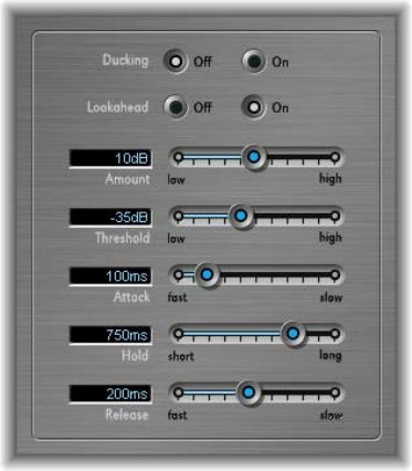
Chapter 4 Dynamics processors 89
Use Ducker
Ducking is a common technique used in radio and television broadcasting. When the DJ or
announcer speaks while music is playing, the music level is automatically reduced. When the
announcement has nished, the music is automatically raised to its original volume level. Ducker
provides a simple means of achieving this result with existing recordings. It does not work in real
time.
Note: For technical reasons, Ducker can be inserted only in output and aux channel strips.
Ducker parameters
•Ducking O/On buttons: Turn ducking on or o.
•Lookahead O/On buttons: Turn on to make sure that Ducker reads the incoming signal before
processing. This results in no latency—it is primarily intended for slower computers.
•Amount slider and eld: Drag to set the amount of volume reduction of the music mix channel
strip—in eect, the output signal.
•Threshold slider and eld: Drag to set the lowest level that a side-chain signal must attain before
it begins to reduce the music mix output level—by the amount set with the Amount slider. If
the side-chain signal level doesn’t reach the threshold, the music mix channel strip volume is
not aected.
•Attack slider and eld: Drag to control how quickly the volume is reduced. If you want the
music mix signal to be gently faded out, set this slider to a high value. The Attack value also
controls whether or not the signal level is reduced before the threshold is reached. The earlier
this occurs, the more latency is introduced.
Note: This only works if the ducking signal is not live—the ducking signal must be an existing
recording. Logic Pro needs to analyze the signal level before it is played back to predene the
point where ducking begins.
•Hold slider and eld: Drag to dene the length of time that the music mix channel strip volume
is reduced. This control prevents a chattering eect that can be caused by a rapidly changing
side-chain level. If the side-chain level hovers around the threshold value rather than clearly
exceeding or falling short of it, set the Hold parameter to a high value to compensate for any
rapid volume reductions.
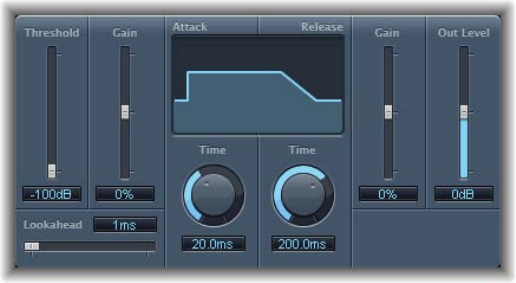
Chapter 4 Dynamics processors 90
•Release slider and eld: Drag to control how quickly the volume returns to the original level. Set
it to a high value if you want the music mix to slowly fade up after the announcement.
Use the Ducker plug-in
1 Insert Ducker into an aux channel strip.
2 Assign all channel strip outputs that are supposed to “duck” (dynamically lower the volume of
the mix) to a bus—the aux channel strip chosen in step 1.
3 In the Ducker plug-in window header, choose the bus that carries the ducking (vocal) signal from
the Side Chain pop-up menu.
Note: Unlike all other side-chain-capable plug-ins, the Ducker side chain is mixed with the
output signal after passing through the plug-in. This ensures that the ducking side-chain
signal—the voiceover—is heard at the output.
4 Adjust the Ducker parameters.
Enveloper
Enveloper is an unusual processor that lets you shape the attack and release phases of a signal—
the signal’s transients, in other words. This makes it a unique tool that can be used to achieve
results that dier from other dynamics processors. In contrast to a compressor or expander,
Enveloper operates independently of the absolute level of the input signal—but this works only
if the Threshold slider is set to the lowest possible value.
The most important Enveloper parameters are the two Gain sliders, one on each side of the
central display. These govern the Attack and Release levels of each respective phase.
Boosting the attack phase can add snap to a drum sound, or it can amplify the initial pluck or
pick sound of a stringed instrument. Attenuating the attack causes percussive signals to fade
in more softly. You can also mute the attack, making it virtually inaudible. A creative use for this
eect is alteration of the attack transients to mask poor timing of recorded instrument parts.
Boosting the release phase also accentuates any reverb applied to the aected channel strip.
Conversely, attenuating the release phase makes reverb-drenched tracks sound drier. This is
particularly useful when you are working with drum loops, but it has many other applications
as well.
Chapter 4 Dynamics processors 91
Enveloper parameters
•Threshold slider and eld: Drag to set the threshold level. Signals that exceed the threshold
have their attack and release phase levels altered. In general, you should set the Threshold
to the minimum value and leave it there. Only when you signicantly raise the release phase
level, which also boosts any noise in the original recording, should you raise the Threshold
slider slightly. This limits Enveloper to aecting only the useful part of the signal.
•(Attack) Gain slider and eld: Drag to boost or attenuate the attack phase of the signal. When
the Gain slider is set to the center position—0%—the signal is unaected.
•Lookahead slider and eld: Drag to set the pre-read analysis time for the incoming signal. The
Lookahead slider denes how far into the future of the incoming signal Enveloper looks,
to anticipate upcoming events. You generally do not need to use this feature, except when
processing signals with extremely sensitive transients. If you do raise the Lookahead value, you
may need to adjust the attack time to compensate.
•Display: Shows the attack and release curves applied to the signal.
•(Attack) Time knob and eld: Rotate to set the time it takes for the signal to increase from the
threshold level to the maximum Gain level. Attack Time values of around 20 ms and Release
Time values of 1500 ms are a good starting point.
•(Release) Time knob and eld: Rotate to set the time it takes for the signal to fall from the
maximum gain level to the threshold level.
•(Release) Gain slider and eld: Drag to boost or attenuate the release phase of the signal. When
the Gain slider is set to the center position—0%—the signal is unaected.
•Out Level slider and eld: Drag to set the level of the output signal. Drastic boosting or cutting
of either the release or attack phase may change the overall level of the signal. You can
compensate for this by adjusting the Out Level slider.
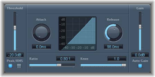
Chapter 4 Dynamics processors 92
Expander
Expander is similar in concept to a compressor, but increases, rather than reduces, the dynamic
range above the threshold level. You can use Expander to add liveliness and freshness to your
audio signals.
Expander parameters
•Threshold slider and eld: Drag to set the threshold level. Signals above this level are expanded.
•Peak/RMS buttons: Click to determine whether the Peak or RMS method is used to analyze
the signal.
•Attack knob and eld: Rotate to set the time it takes for Expander to respond to signals that
exceed the threshold level.
•Expansion display: Shows the expansion curve applied to the signal.
•Release knob and eld: Rotate to set the time it takes for Expander to stop processing the signal
after it falls below the threshold level.
•Ratio slider and eld: Drag to set the expansion ratio—the ratio of signal expansion when the
threshold is exceeded.
Note: Because Expander is a genuine upward expander—in contrast to a downward expander,
which increases the dynamic range below the Threshold—the Ratio slider features a value
range of 1:1 to 0.5:1.
•Knee slider and eld: Drag to determine the strength of expansion at levels close to the
threshold. Lower values result in more severe or immediate expansion—hard knee. Higher
values result in a gentler expansion—soft knee.
•Gain slider and eld: Drag to set the amount of output gain.
•Auto Gain button: Turn on to compensate for the level increase caused by expansion. When
Auto Gain is active, the signal sounds softer, even when the peak level remains the same.
Note: If you dramatically change the dynamics of a signal (with extreme Threshold and Ratio
values), you may need to reduce the Gain slider level to avoid distortion. In most cases, turning
on Auto Gain adjusts the signal appropriately.
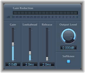
Chapter 4 Dynamics processors 93
Limiter
Limiter works much like a compressor but with one important dierence: where a compressor
proportionally reduces the signal when it exceeds the threshold, a limiter reduces any peak
above the threshold to the threshold level, eectively limiting the signal to this level.
Limiter is used primarily when mastering. Typically, you apply Limiter as the very last process in
the mastering signal chain, where it raises the overall volume of the signal so that it reaches, but
does not exceed, 0 dB.
Limiter is designed in such a way that if set to 0 dB Gain and 0 dB Output Level, it has no eect
on a normalized signal. If the signal clips, Limiter reduces the level before clipping can occur.
Limiter cannot, however, x audio that is clipped during recording.
Limiter parameters
•Gain reduction meter: Shows the amount of limiting in real time.
•Gain slider and eld: Drag to set the amount of gain applied to the input signal.
•Lookahead slider and eld: Drag to adjust how far ahead (in milliseconds) Limiter analyzes
the audio signal. This enables it to react earlier to peak volumes by adjusting the amount
of reduction.
Note: Lookahead causes latency, but this has no perceptible eect when you use Limiter as a
mastering eect on prerecorded material. Set it to higher values if you want the limiting eect
to occur before the maximum level is reached, thus creating a smoother transition.
•Release slider and eld: Drag to set the time it takes for Limiter to stop processing, after the
signal falls below the threshold level.
•Output Level knob and eld: Rotate to set the output level of the signal.
•Softknee button: Turn on to limit the signal only when it reaches the threshold. The transition to
full limiting is nonlinear, producing a softer, less abrupt eect, and reducing distortion artifacts
that can be produced by hard limiting.
•Inter Sample Peak Detection checkbox (Extended Parameters area): Select to detect inter-sample
peaks in the signal.
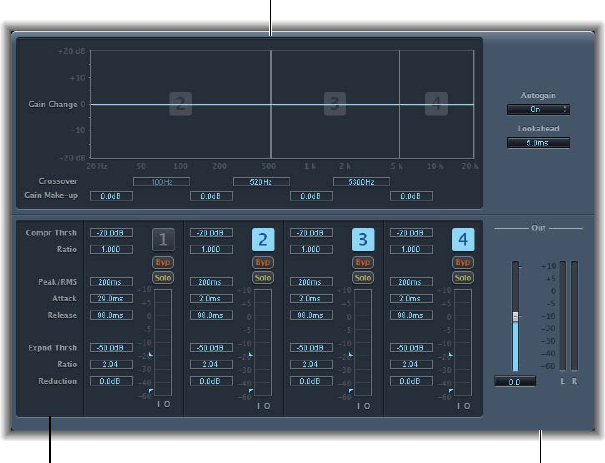
Chapter 4 Dynamics processors 94
Multipressor
Multipressor overview
Multipressor (an abbreviation for multiband compressor) is a versatile audio mastering tool. It
splits the incoming signal into dierent frequency bands—up to four—and enables you to
independently compress each band. After compression is applied, the bands are combined into a
single output signal.
The advantage of compressing dierent frequency bands separately is that it allows more
compression to be applied to bands that need it, without aecting other bands. This avoids the
“pumping” eect often associated with high amounts of compression.
Because the use of higher compression ratios on specic frequency bands is possible,
Multipressor can achieve a higher average volume without causing audible artifacts.
Raising the overall volume level can result in a corresponding increase in the existing noise oor.
Each frequency band features downward expansion, which enables you to reduce or suppress
this noise.
Downward expansion works as a counterpart to compression. Whereas a compressor compresses
the dynamic range of higher volume levels, the downward expander expands the dynamic range
of the lower volume levels. With downward expansion, the signal is reduced in level when it falls
below the threshold level. This works in a similar way to a noise gate, but rather than abruptly
cutting o the sound, it smoothly fades the volume with an adjustable ratio.
Multipressor Display parameters
Multipressor’s parameters are grouped into three main areas: the graphic display in the upper
section, the set of controls for each frequency band in the lower section, and the output
parameters on the right.
Frequency band section
Graphic display section
Output section
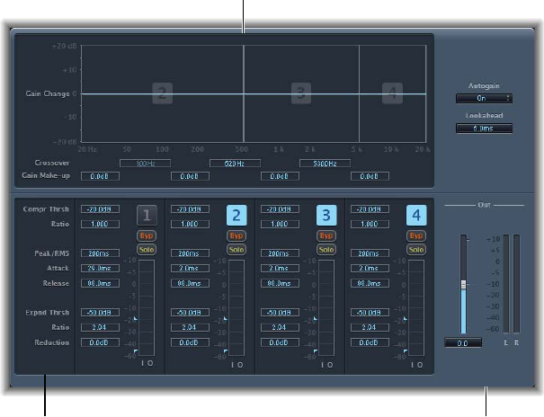
Chapter 4 Dynamics processors 95
Display parameters
•Graphic display: Shows and allows adjustment of frequency and gain for each frequency band.
The amount of gain change from 0 dB is indicated by blue bars. The band number appears in
the center of active bands. You can adjust each frequency band in the following ways:
•Drag the horizontal bar up or down to adjust the gain makeup for that band.
•Drag the vertical edges of a band to the left or right to set the crossover frequencies, which
adjusts the band’s frequency range.
•Crossover elds: Drag to set the crossover frequency between adjacent bands.
•Gain Make-up elds: Drag to set the amount of the gain make-up for each band.
Multipressor Frequency Band parameters
Multipressor’s parameters are grouped into three main areas: the graphic display in the upper
section, the set of controls for each frequency band in the lower section, and the output
parameters on the right.
Frequency band section
Graphic display section
Output section
Frequency band parameters
•Compr Thresh (Compression Threshold) elds: Drag to set the compression threshold for the
selected band. Setting the parameter to 0 dB results in no compression of the band.
•Compr Ratio (Compression Ratio) elds: Drag to set the compression ratio for the selected band.
Setting the parameter to 1:1 results in no compression of the band.
•Expnd Thresh (Expand Threshold) elds: Drag to set the expansion threshold for the selected
band. Setting the parameter to its minimum value (−60 dB) means that only signals that fall
below this level are expanded.
•Expnd Ratio (Expand Ratio) elds: Drag to set the expansion ratio for the selected band.
•Expnd Reduction (Expand Reduction) elds: Drag to set the amount of downward expansion for
the selected band.
•Peak/RMS elds: Drag to set a smaller value for shorter peak detection, or a larger value for RMS
detection, in milliseconds.

Chapter 4 Dynamics processors 96
•Attack elds: Drag to set the time before compression starts for the selected band, after the
signal exceeds the threshold.
•Release elds: Drag to set the time before compression stops on the selected band, after the
signal falls below the threshold.
•Band on/o buttons: Turn each band on or o. When enabled, the button is highlighted, and
the corresponding band appears in the graphic display area above.
•Byp(ass) buttons: Turn on to bypass the selected frequency band.
•Solo buttons: Turn on to hear compression on only the selected frequency band.
•Level meters: The bar on the left shows the input level, and the bar on the right shows the
output level.
•Threshold arrows: Two arrows appear to the left of each Level meter.
•Click the upper arrow to adjust the Compression Threshold (Compr Thresh).
•Click the lower arrow to adjust the Expansion Threshold (Expnd Thresh).
Multipressor Output parameters
Multipressor’s parameters are grouped into three main areas: the graphic display in the upper
section, the set of controls for each frequency band in the lower section, and the output
parameters on the right.
Frequency band section
Graphic display section
Output section
Output parameters
•Auto Gain button: Turn on to reference the overall processing of the signal to 0 dB, making the
output louder.
•Lookahead value eld: Drag to set how far ahead the eect analyzes the incoming signal,
allowing faster reactions to peak volumes.
•Out slider: Drag to set the overall gain at Multipressor’s output.
•Level meter: Shows the overall output level.
Chapter 4 Dynamics processors 97
Use Multipressor
In the graphic display, the blue bars show the gain change—not merely the gain reduction—as
with a standard compressor. The gain change display is a composite value consisting of the
compression reduction, plus the expander reduction, plus the auto gain compensation, plus the
gain make-up.
Compression parameters
The Compression Threshold and Compression Ratio parameters are the key parameters for
controlling compression. Usually the most useful combinations of these two settings are a low
Compression Threshold with a low Compression Ratio, or a high Compression Threshold with a
high Compression Ratio.
Downward Expansion parameters
The Expansion Threshold, Expansion Ratio, and Expansion Reduction parameters are the key
parameters for controlling downward expansion. They determine the strength of the expansion
applied to the chosen range.
Peak/RMS and Envelope parameters
Adjusting the parameter between Peak (0 ms, minimum value) and RMS (root mean square
−200 ms, maximum value) is dependent on the type of signal you want to compress. An
extremely short Peak detection setting is suitable for compression of short and high peaks of low
power, which do not typically occur in music. The RMS detection method measures the power
of the audio material over time and thus works much more musically. This is because human
hearing is more responsive to the overall power of the signal than to single peaks. As a basic
setting for most applications, the centered position is recommended.
Output parameters
The Out slider sets the overall output level. Set Lookahead to higher values when the Peak/RMS
elds are set to higher values (farther towards RMS). Set Auto Gain to On to reference the overall
processing to 0 dB, making the output louder.
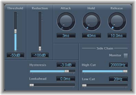
Chapter 4 Dynamics processors 98
Noise Gate
Noise Gate overview
Noise Gate is commonly used to suppress unwanted noise that is audible when the audio signal
is at a low level. You can use it to remove background noise, crosstalk from other signal sources,
and low-level hum, among other uses.
Noise Gate works by allowing signals above the threshold level to pass unimpeded, while
reducing signals below the threshold level. This eectively removes lower-level parts of the
signal, while allowing the desired parts of the audio to pass.
Noise Gate parameters
•Threshold slider and eld: Drag to set the threshold level. Signals that fall below the threshold
are reduced in level.
•Reduction slider and eld: Drag to set the amount of signal reduction.
•Attack knob and eld: Rotate to set the time it takes to fully open the gate after the signal
exceeds the threshold.
•Hold knob and eld: Rotate to set the time the gate is kept open after the signal falls below
the threshold.
•Release knob and eld: Rotate to set the time it takes to reach maximum attenuation after the
signal falls below the threshold.
•Hysteresis slider and eld: Drag to set the dierence (in decibels) between the threshold values
that open and close the gate. This prevents the gate from rapidly opening and closing when
the input signal level is close to the threshold level.
•Lookahead slider and eld: Drag to set how far ahead Noise Gate analyzes the incoming signal,
allowing the eect to respond more quickly to peak levels.
•Monitor button: Turn on to hear the side-chain signal, including the eect of the High Cut and
Low Cut lters.
•High Cut slider and eld: Drag to set the upper cuto frequency for the side-chain signal.
•Low Cut slider and eld: Drag to set the lower cuto frequency for the side-chain signal.
Note: When no external side chain is selected, the input signal is used as the side chain.
Chapter 4 Dynamics processors 99
Use Noise Gate
In most situations, setting the Reduction slider to the lowest possible value ensures that sounds
below the Threshold value are completely suppressed. Setting Reduction to a higher value
attenuates low-level sounds but still allows them to pass. You can also use Reduction to boost
the signal by up to 20 dB, which is useful for ducking eects.
The Attack, Hold, and Release knobs modify the dynamic response of Noise Gate. If you want
the gate to open extremely quickly for percussive signals such as drums, set the Attack knob to
a lower value. For sounds with a slow attack phase, such as string pads, set Attack to a higher
value. Similarly, when working with signals that fade out gradually or that have longer reverb
tails, set a higher Release knob value that allows the signal to fade out naturally.
The Hold knob determines the minimum amount of time that the gate stays open. You can use
the Hold knob to prevent abrupt level changes—known as chattering—caused by rapid opening
or closing of the gate.
The Hysteresis slider provides another option for preventing chattering, without needing to
dene a minimum Hold time. Use it to set the range between the threshold values that open
and close the gate. This is useful when the signal level hovers around the Threshold level, causing
Noise Gate to switch on and o repeatedly, and producing the undesirable chattering eect. The
Hysteresis slider essentially sets the gate to open at the Threshold level and remain open until
the level drops below another, lower, level. As long as the dierence between these two values
is large enough to accommodate the uctuating level of the incoming signal, Noise Gate can
function without creating chatter. This value is always negative. Generally, −6 dB is a good place
to start.
In some situations, you may nd that the level of the signal you want to keep and the level of the
noise signal are close, making it dicult to separate them. For example, when you are recording
a drum kit and using Noise Gate to isolate the sound of the snare drum, the hi-hat may also open
the gate in many cases. To remedy this, use the side-chain controls to isolate the desired trigger
signal with the High Cut and Low Cut lters.
Important: The side-chain signal is used only as a detector/trigger in this situation. The lters are
used to isolate particular trigger signals in the side-chain source, but they have no inuence on
the actual gated signal—the audio being routed through Noise Gate.
Use the side-chain lters
1 Click the Monitor button to hear how the High Cut and Low Cut lters will aect the incoming
trigger signal.
2 Drag the High Cut slider to set the upper frequency.
Trigger signals above this are ltered.
3 Drag the Low Cut slider to set the lower frequency.
Trigger signals below this are ltered.
The lters allow only very high (loud) signal peaks to pass. In the drum kit example above, you
could remove the hi-hat signal, which is higher in frequency, with the High Cut lter and allow
the snare signal to pass. Turn o monitoring to set a suitable Threshold level more easily.
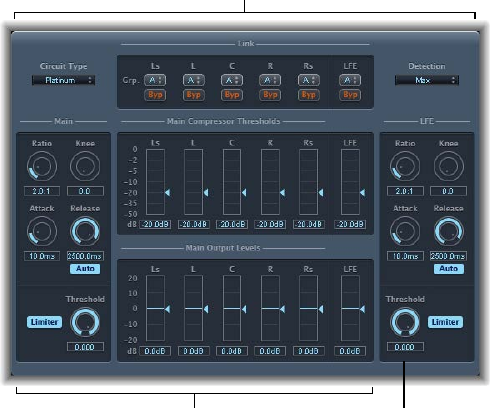
Chapter 4 Dynamics processors 100
Surround Compressor
Surround Compressor overview
Surround Compressor, based on the Compressor plug-in, is specically designed for compression
of complete surround mixes. It is commonly inserted in a surround output channel strip or in
audio or aux channel strips—busses—that carry multichannel audio.
You can adjust the compression ratio, knee, attack, and release for the main, side, surround, and
LFE channels, depending on the chosen surround format. All channels include an integrated
limiter and provide independent threshold and output level controls.
You can link channels by assigning them to one of three groups. When you adjust the threshold
or output parameter of any grouped channel, the parameter adjustment is mirrored by all
channels assigned to the group.
LFE sectionMain section
Link section
Surround Compressor’s interface is divided into three sections:
•The Link section at the top contains menus used to assign each channel to a group. See
Surround Compressor Link parameters on page 101.
•The Main section includes controls common to all the main channels and the threshold and
output controls for each channel. See Surround Compressor Main parameters on page 102.
•The LFE section on the lower right includes separate controls for the LFE channel. See
Surround Compressor LFE parameters on page 103.
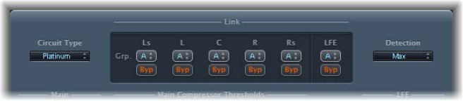
Chapter 4 Dynamics processors 101
Surround Compressor Link parameters
Surround Compressor’s Link section provides the following parameters.
Link parameters
•Circuit Type pop-up menu: Choose the type of circuit emulated by Surround Compressor. The
choices are Platinum, Classic A_R, Classic A_U, VCA, FET, and Opto (optical).
•Grp. (Group) pop-up menus: Set group membership for each channel (A, B, C, or no group
(indicated by -). Moving the Threshold or Output Level slider for any grouped channel moves
the sliders for all channels assigned to that group.
Tip: Press Command and Option while moving the Threshold or Output Level slider of
a grouped channel to temporarily unlink the channel from the group. This lets you set
independent threshold settings while maintaining the side-chain detection link necessary for
a stable surround image.
•Byp (Bypass) buttons: Click to bypass the channel. If the channel belongs to a group, all
grouped channels are bypassed.
•Detection pop-up menu: Choose the signal type to exceed or fall below the threshold. Max uses
the maximum level of each signal. Sum uses the summed level of all signals.
•If Max is chosen and any of the surround channels exceeds or falls below the threshold, that
channel (or group of channels) is compressed.
•If Sum is chosen, the combined level of all channels must exceed the threshold before
compression occurs.
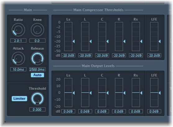
Chapter 4 Dynamics processors 102
Surround Compressor Main parameters
Surround Compressor’s Main section provides the following parameters.
Main parameters
•Ratio knob and eld: Rotate to set the ratio of signal reduction when the threshold is exceeded.
•Knee knob and eld: Rotate to set the ratio of compression at levels close to the threshold.
•Attack knob and eld: Rotate to set the time it takes to reach full compression, after the signal
exceeds the threshold.
•Release knob and eld: Rotate to set the time it takes to return to zero compression, after the
signal falls below the threshold.
•Auto button: Turn on to dynamically adjust the release time to the audio material.
•Limiter button: Turns limiting for the main channels on or o.
•Threshold knob and eld: Rotate to set the threshold for the limiter on the main channels.
•Main Compressor Threshold sliders and elds: Drag to set the threshold level for each channel—
including the LFE channel, which also has independent controls.
•Main Output Levels sliders and elds: Drag to set the output level for each channel—including
the LFE channel, which has independent controls.
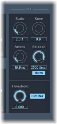
Chapter 4 Dynamics processors 103
Surround Compressor LFE parameters
Surround Compressor’s LFE section provides the following parameters.
LFE parameters
•Ratio knob and eld: Rotate to set the compression ratio for the LFE channel.
•Knee knob and eld: Rotate to set the knee for the LFE channel.
•Attack knob and eld: Rotate to set the attack time for the LFE channel.
•Release knob and eld: Rotate to set the release time for the LFE channel.
•Auto button: Turn on to automatically adjust the release time to the audio signal.
•Threshold knob and eld: Rotate to set the threshold for the limiter on the LFE channel.
•Limiter button: Turns limiting on or o for the LFE channel.
104
Equalizers overview
An equalizer (commonly abbreviated as EQ) shapes the sound of incoming audio by changing
the level of specic frequency bands.
Equalization is one of the most-used audio processes, both for music projects and in post-
production work for video. You can use EQ to subtly or signicantly shape the sound of an
audio le, an instrument, a vocal performance, or a project by adjusting specic frequencies or
frequency ranges.
All EQs are specialized lters that allow certain frequencies to pass through unchanged while
raising (boosting) or lowering (cutting) the level of other frequencies. Some EQs can be used
in a “broad-brush” fashion, to boost or cut a large range of frequencies. Other EQs, particularly
parametric and multiband EQs, can be used for more precise control.
The simplest types of EQs are single-band EQs, which include low cut and high cut, lowpass and
highpass, shelving, and parametric EQs.
Multiband EQs (such as Channel EQ or Linear Phase EQ) combine several lters in one unit,
enabling you to control a large part of the frequency spectrum. Multiband EQs allow you to
independently set the frequency, bandwidth, and Q factor of each frequency spectrum band.
This provides extensive and precise tone-shaping of any audio source, be it an individual audio
signal or an entire mix.
Channel EQ
Channel EQ overview
Channel EQ is a versatile multiband EQ. It provides eight frequency bands, including lowpass and
highpass lters, low and high shelving lters, and four exible parametric bands. It also features
an integrated Fast Fourier Transform (FFT) Analyzer that shows changes to the frequency curve
of the audio signal in real time, allowing you to see which parts of the frequency spectrum may
need adjustment.
You can use Channel EQ to shape the sound of individual tracks or audio les or for tone-shaping
on an overall project mix. The Analyzer and graphic display’s controls make it easy to view and
change the audio signal in real time.
Tip: The parameters of Channel EQ and Linear Phase EQ are identical, enabling you to freely
copy settings between them. In Logic Pro X, if you replace a Channel EQ with a Linear Phase EQ
(or vice versa) in the same Insert slot, the current settings are automatically transferred to the
new EQ.
Equalizers 5
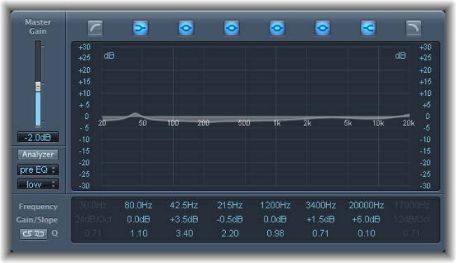
Chapter 5 Equalizers 105
Channel EQ parameters
The left side of the Channel EQ window features the Gain and Analyzer controls. The central area
of the window includes the graphic display and parameters for shaping each EQ band.
Channel EQ parameters
•Master Gain slider and eld: Drag to set the overall output level of the signal. Use it after
boosting or cutting individual frequency bands.
•Analyzer button: Turns the Analyzer on or o.
•Pre/Post EQ button: Determines whether the Analyzer shows the frequency curve before or
after EQ is applied, when Analyzer mode is active.
•Resolution pop-up menu: Choose the sample resolution for the Analyzer. Choose from the
following menu items: low (1024 points), medium (2048 points), and high (4096 points).
•Band On/O buttons: Turn the corresponding band on or o. Each button’s icon indicates the
lter type:
•Band 1 is a highpass lter.
•Band 2 is a low shelving lter.
•Bands 3 through 6 are parametric bell lters.
•Band 7 is a high shelving lter.
•Band 8 is a lowpass lter.
•Graphic display: Shows the current curve of each EQ band. The scale is shown in dB.
•Drag horizontally in the section of the display that encompasses each band to adjust the
frequency of the band.
•Drag vertically in the section of the display that encompasses each band to adjust the gain
of each band (except bands 1 and 8). The display reects your changes immediately.
•Drag the pivot point in each band to adjust the Q factor. Q is shown beside the pointer
when it is moved over a pivot point.
•Frequency elds: Drag to adjust the frequency of each band.
•Gain/Slope elds: Drag to set the amount of gain for each band. For bands 1 and 8, this
changes the slope of the lter.
•Q elds: Drag to adjust the Q factor or resonance for each band—the range of frequencies
around the center frequency that are aected.
Chapter 5 Equalizers 106
Note: The Q parameter of band 1 and band 8 has no eect when the slope is set to 6 dB/Oct.
When the Q parameter is set to an extremely high value, such as 100, these lters aect only a
very narrow frequency band and can be used as notch lters.
•Link button: Turns on Gain-Q coupling, which automatically adjusts the Q (bandwidth) when
you raise or lower the gain on any EQ band, to preserve the perceived bandwidth of the bell
curve.
•Analyzer Mode buttons (Extended Parameters area): Click to choose Peak or RMS.
•Analyzer Decay slider and eld (Extended Parameters area): Drag to set the decay rate (in dB per
second) of the Analyzer curve (peak decay in Peak mode or an averaged decay in RMS mode).
•Gain-Q Couple Strength pop-up menu (Extended Parameters area): Choose the amount of Gain-Q
coupling.
•Strong: Preserves most of the perceived bandwidth.
•Light or medium: Allows some change as you raise or lower the gain.
•Asymmetric: These settings feature a stronger coupling for negative gain values than for
positive values, so the perceived bandwidth is more closely preserved when you cut, rather
than boost, gain.
Note: If you play back automation of the Q parameter with a dierent Gain-Q Couple Strength
setting, the actual Q values will be dierent than when the automation was recorded.
Channel EQ use tips
The way you use Channel EQ depends on the audio material and your intended outcome. A
useful workow for many situations is as follows: Set the Channel EQ to a at response (no
frequencies boosted or cut), turn on the Analyzer, and play the audio signal. Watch the graphic
display to see which parts of the frequency spectrum have frequent peaks and which parts of
the spectrum stay at a low level. Pay attention to sections where the signal distorts or clips. Use
the graphic display or parameter controls to adjust the frequency bands.
You can reduce or eliminate unwanted frequencies, and you can raise quieter frequencies to
make them more pronounced. You can adjust the center frequencies of bands 2 through 7 to
aect a specic frequency—either one you want to emphasize, such as the root note of the
music, or one you want to eliminate, such as hum or other noise. While doing so, change the
Q parameter or parameters so that only a narrow range of frequencies is aected, or widen it to
alter a broader frequency area.
Each EQ band has a dierent color in the graphic display. You can graphically adjust the
frequency of a band by dragging horizontally. Drag vertically to adjust the amount of gain for
the band. For bands 1 and 8, the slope values can be changed only in the parameter area below
the graphic display. Each band has a pivot point (a small circle on the curve) at the location
of the band’s frequency; you can adjust the Q or width of the band by dragging the pivot
point vertically.
You can also adjust the decibel scale of the graphic display by vertically dragging either the left
or right edge of the display, where the dB scale is shown, when the Analyzer is not active. When
the Analyzer is active, dragging the left edge adjusts the linear dB scale, and dragging the right
edge adjusts the Analyzer dB scale.
To increase the resolution of the EQ curve display in the area around the zero line, drag the dB
scale, on the left side of the graphic display upward. Drag downward to decrease the resolution.
Chapter 5 Equalizers 107
Channel EQ Analyzer
The Analyzer uses a mathematical process called a Fast Fourier Transform (FFT) to provide a real-
time curve of all frequency components in the incoming signal. This is superimposed over any
EQ curves you have set. The Analyzer curve uses the same scale as the EQ curves, making it easy
to recognize important frequencies in the incoming audio. This also simplies the task of setting
EQ curves to raise or lower the levels of frequencies and frequency ranges.
The bands derived from FFT analysis are scaled logarithmically—there are more bands in higher
octaves than in lower octaves.
As soon as the Analyzer is activated, you can change the scaling with the Analyzer Top parameter
on the right side of the graphic display. The visible area represents a dynamic range of 60 dB.
Drag vertically to set the maximum value to anywhere between +20 dB and −80 dB. The
Analyzer display is always dB-linear.
Note: High Analyzer resolutions require signicantly more processing power. High resolution is
necessary when trying to obtain accurate analysis of very low bass frequencies, for example. It
is recommended that you turn o the Analyzer or close the Channel EQ window after setting
EQ parameters.
Linear Phase EQ
Linear Phase EQ overview
The high-quality Linear Phase EQ eect is similar to Channel EQ, sharing the same parameters
and eight-band layout. You can copy settings between them. In Logic Pro, if you replace
Channel EQ with Linear Phase EQ (or vice versa) in the same Insert slot, the current settings are
automatically transferred to the new EQ.
Linear Phase EQ uses a dierent underlying technology that preserves the phase of the audio
signal. Phase coherency is always maintained, even when you apply extreme EQ curves to the
sharpest signal transients.
A further dierence between Channel EQ and Linear Phase EQ is that the latter uses a xed
amount of CPU resources, regardless of the number of active bands. Linear Phase EQ also
introduces greater amounts of latency.
Note: It is recommended that you use Linear Phase EQ for mastering recorded audio and avoid
use when playing software instruments live, for example. You may need to use the latency
compensation feature of Logic Pro when using Linear Phase EQ.
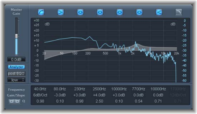
Chapter 5 Equalizers 108
Linear Phase EQ parameters
The left side of the Channel EQ window incorporates the Gain and Analyzer controls. The central
area of the window includes the graphic display and parameters for shaping each EQ band.
Linear Phase EQ parameters
•Master Gain slider and eld: Drag to set the overall output level of the signal after boosting or
cutting individual frequency bands.
•Analyzer button: Click to turn the Analyzer on or o.
•Pre/Post EQ button: Click to determine if the Analyzer shows the frequency curve before or
after EQ is applied, when Analyzer mode is active.
•Resolution pop-up menu: Choose the sample resolution for the Analyzer. Choose from the
following menu items: low (1024 points), medium (2048 points), and high (4096 points).
•Band On/O buttons: Turn the corresponding band on or o. Each button’s icon indicates the
lter type:
•Band 1 is a highpass lter.
•Band 2 is a low shelving lter.
•Bands 3 through 6 are parametric bell lters.
•Band 7 is a high shelving lter.
•Band 8 is a lowpass lter.
•Graphic display: Shows the current curve of each EQ band. The scale is shown in dB.
•Drag horizontally in the section of the display that encompasses each band to adjust the
frequency of the band.
•Drag vertically in the section of the display that encompasses each band to adjust the gain
of each band (except bands 1 and 8). The display reects your changes immediately.
•Drag the pivot point in each band to adjust the Q factor. Q is shown beside the pointer
when it is moved over a pivot point.
•Frequency elds: Drag to adjust the frequency of each band.
•Gain/Slope elds: Drag to set the amount of gain for each band. For bands 1 and 8, this
changes the slope of the lter.
•Q elds: Drag to adjust the Q or resonance for each band—the range of frequencies around
the center frequency that are aected.
Chapter 5 Equalizers 109
Note: The Q parameter of band 1 and band 8 has no eect when the slope is set to 6 dB/Oct.
When the Q parameter is set to an extremely high value (such as 100), these lters aect only a
very narrow frequency band and can be used as notch lters.
•Link button: Click to turn on Gain-Q coupling, which automatically adjusts the Q (bandwidth)
when you raise or lower the gain on any EQ band, to preserve the perceived bandwidth of the
bell curve.
•Analyzer Mode buttons (Extended Parameters area): Click to choose Peak or RMS.
•Analyzer Decay slider and eld (Extended Parameters area): Drag to adjust the decay rate
(in dB per second) of the Analyzer curve (peak decay in Peak mode or an averaged decay in
RMS mode).
•Gain-Q Couple Strength pop-up menu (Extended Parameters area): Choose the amount of Gain-Q
coupling.
•Strong: Preserves most of the perceived bandwidth.
•Light and medium: Allows some change as you raise or lower the gain.
•Asymmetric: Features a stronger coupling for negative gain values than for positive values, so
the perceived bandwidth is more closely preserved when you cut, rather than boost, gain.
Note: If you play back automation of the Q parameter with a dierent Gain-Q Couple
Strength setting, the actual Q values will be dierent than they were when the automation
was recorded.
Linear Phase EQ use tips
Linear Phase EQ is typically used as a mastering tool that is inserted into master or output
channel strips. The way you use Linear Phase EQ depends on the audio material and your
intended outcome. A useful workow for many situations is as follows: Set Linear Phase EQ to
a at response (no frequencies boosted or cut), turn on the Analyzer, then play the audio signal.
Watch the graphic display to see which parts of the frequency spectrum have frequent peaks
and which parts of the spectrum stay at a low level. Pay attention to sections where the signal
distorts or clips. Use the graphic display or parameter controls to adjust the frequency bands.
You can reduce or eliminate unwanted frequencies and you can raise quieter frequencies to
make them more pronounced. You can adjust the center frequencies of bands 2 through 7
to aect a specic frequency—either one you want to emphasize, such as the root note of
the music, or one you want to eliminate, such as hum or other noise. Use the Q parameter or
parameters so that only a narrow range of frequencies is aected.
Each EQ band has a dierent color in the graphic display. You can graphically adjust the
frequency of a band by dragging horizontally. Drag vertically to adjust the amount of gain for
the band. For bands 1 and 8, the slope values can be changed only in the parameter area below
the graphic display. Each band has a pivot point (a small circle on the curve) at the location
of the band’s frequency; you can adjust the Q or width of the band by dragging the pivot
point vertically.
You can adjust the decibel scale of the graphic display by vertically dragging either the left
or right edge of the dB scale when the Analyzer is not active. When the Analyzer is active,
dragging the left edge adjusts the linear dB scale, and dragging the right edge adjusts the
Analyzer dB scale.
To increase the resolution of the EQ curve display in the area around the zero line, drag the left
side of the dB scale upward. Drag downward to decrease the resolution.
Chapter 5 Equalizers 110
Linear Phase EQ Analyzer
The Analyzer uses a mathematical process called a Fast Fourier Transform (FFT) to provide a real-
time curve of all frequency components in the incoming signal. This is superimposed over any
EQ curves you have set. The Analyzer curve uses the same scale as the EQ curves, making it easy
to recognize important frequencies in the incoming audio. This also simplies the task of setting
EQ curves to raise or lower the levels of frequencies or frequency ranges.
The bands derived from FFT analysis are scaled logarithmically—there are more bands in higher
octaves than in lower octaves.
As soon as the Analyzer is activated, you can change the scaling with the Analyzer Top parameter
on the right side of the graphic display. The visible area represents a dynamic range of 60 dB.
Drag vertically to set the maximum value to anywhere between +20 dB and −40 dB. The
Analyzer display is always dB-linear.
Note: High Analyzer resolutions require signicantly more processing power. High resolution is
necessary when trying to obtain accurate analysis of very low bass frequencies, for example. It
is recommended that you turn o the Analyzer or close the Channel EQ window after setting
EQ parameters.
Match EQ
Match EQ overview
Match EQ allows you to analyze and store the average frequency spectrum of an audio le as a
template. You can apply this template to another audio signal so that it matches the spectrum
of the original le. This is also known as a ngerprint EQ, where one sonic ngerprint is applied to
another signal.
Match EQ enables you to acoustically match the tonal quality or overall sound of dierent songs
you plan to include on an album, for example, or to impart the color of any source recording to
your own projects.
Match EQ is a learning equalizer that analyzes the frequency spectrum of an audio signal such as
an audio le, a channel strip input signal, or a template. The average frequency spectrum of the
source le (the template) and of the current material (this can be the entire project or individual
channel strips within it) is analyzed. These two spectra are then matched, creating a lter curve.
This lter curve adapts the frequency response of the current material to match that of the
template. Before applying the lter curve, you can modify it by boosting or cutting any number
of frequencies or by inverting the curve.
The Analyzer allows you to visually compare the frequency spectrum of the source le and
the resulting curve, making it easier to make manual corrections at specic points within
the spectrum.
Note: Although Match EQ acoustically matches the frequency curve of two audio signals, it does
not match any dynamic dierences between the two signals.
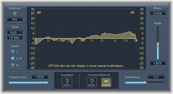
Chapter 5 Equalizers 111
Match EQ parameters
Match EQ oers the following parameters.
Match EQ parameters
•Analyzer button: Turns the Analyzer function on or o.
•Pre/Post button: Click to determine if the Analyzer looks at the signal before (Pre) or after (Post)
the lter curve is applied.
•View pop-up menu: Set the information shown in the graphic display. Choices are:
•Auto: Displays information for the current function, as set with the active button below the
graphic display.
•Template: Displays the learned frequency curve template for the source le. This is shown in
red.
•Current Material: Displays the frequency curve for the audio learned as current material. This
is shown in green.
•Filter: Displays the lter curve created by matching the template and the current material.
This is shown in yellow.
•View button: Determines if separate curves are displayed by the Analyzer (L&R for stereo, All
Cha for surround) or the summed maximum level is shown (LR Max for stereo, Cha Max for
surround).
Note: The View parameters are disabled when you use the eect on a mono channel.
•Select buttons: Apply changes to the lter curve (created by matching the template with the
current material) to: the left (L), right (R), or both channels (L+R).
Note: The Select parameters are disabled when you use the eect on a mono channel.
•Select pop-up menu (Surround instances only): Choose an individual channel or all channels.
Changes to the lter curve aect the chosen channel when a single channel is selected.
•Channel Link slider and eld: Drag to rene settings made with the Select buttons or Select
pop-up menu.
•When set to 100%, all channels (L and R for stereo, or all surround channels) are represented
by a common EQ curve.
•When set to 0%, a separate lter curve is displayed for each channel (chosen with the Select
buttons or Select pop-up menu).
Chapter 5 Equalizers 112
•Settings between 0 and 100% blend these values with your lter curve changes for each
channel. This results in a hybrid curve.
Note: The Channel Link parameters are disabled when you use the eect on a mono channel.
•LFE Handling buttons (Extended Parameters area): In surround instances, click to process or
bypass the LFE channel.
•Graphic display: Displays the lter curve created by matching the template to the current
material. You can edit the lter curve (see Edit the Match EQ lter curve on page 115 ).
•Template Learn button: Starts/stops the process of learning the frequency spectrum of the
source le.
•Current Material Learn button: Starts/stops the process of learning the frequency spectrum of
the project you want to match with the source le.
•Current Material Match button: Click to match the frequency spectrum of the current material
to that of the template (source) le.
•Phase pop-up menu: Switches the operational principle of the lter curve.
•Linear: Prevents processing from altering the signal phase, but latency is higher.
•Minimal: Alters the signal phase (slightly), but latency is reduced.
•Minimal, Zero Latency: Adds no latency, but has a higher CPU overhead than the
other options.
•Apply slider and eld: Drag to determine the impact of the lter curve on the signal.
•Values above 100% magnify the eect.
•Values below 100% reduce it.
•Negative values (−1% to −100%) invert the peaks and troughs in the lter curve.
•A value of 100% has no impact on the lter curve.
•Smoothing slider and eld: Drag to set the amount of smoothing for the lter curve, using a
constant bandwidth set in semitone steps. A value of 0.0 has no impact on the lter curve.
A value of 1.0 means a smoothing bandwidth of one semitone. A value of 4.0 means a
smoothing bandwidth of four semitones (a major third). A value of 12.0 means a smoothing
bandwidth of one octave, and so on.
Note: Smoothing has no eect on any manual changes you make to the lter curve.
•Fade Extremes checkbox (Extended Parameters area): Select to smooth the lter curve at the
high and low extremes of the frequency spectrum.
Chapter 5 Equalizers 113
Use Match EQ
These tasks are those commonly used with Match EQ to match the frequency spectrum of a mix
with the spectrum of a source audio le. You can adapt some, or all, to your own workow.
Learn or create a Match EQ template
You can drag an audio le to the Template Learn or Current Material Learn buttons for use as
either the template or the current material. A progress bar appears while Match EQ is analyzing
the le. You can also load a previously saved plug-in setting, or you can import the settings of
another unsaved Match EQ instance by copying and pasting.
Do one of the following:
mDrag an audio le from the Finder to the Template Learn button, and select the source channel
strip as a sidechain.
mUse Match EQ on the source channel strip and save a setting. Import this setting into the target
Match EQ instance.
The lter curve is updated automatically each time a new template or current material spectrum
is learned or loaded when the Match button is turned on. You can alternate between the
matched (and possibly scaled or manually modied) lter curve and a at response by turning
the Match button on or o.
Match the EQ of a project mix to the EQ of a source audio le
1 In the project you want to match to the source audio le, insert Match EQ (typically on Output
1-2).
2 Drag the source audio le to the Template Learn button.
3 Return to the start of your mix, click Current Material Learn, and play your mix (the current
material) from start to nish.
4 When you are done, click Current Material Match (this automatically turns o the Current Material
Learn button).
When you click either of the Learn buttons, the View parameter is set to Automatic and the
graphic display shows the frequency curve for the function. You can review any of the frequency
curves when no le is being processed by choosing one of the other View options.
Note: Only one of the Learn buttons can be turned on at a time. For example, if the Learn button
in the Template section is on and you click the Learn button in the Current Material section,
analysis of the template le stops, the current status is used as the spectral template, and analysis
of the incoming audio signal (Current Material) begins.
Edit spectra with the Match EQ shortcut menu
This menu provides commands that can be applied to the spectrums of either the template or
the current material.
mControl-click (or right-click) either Learn button, then choose one of the following from the
shortcut menu:
•Clear Current Material Spectrum: Clears the current spectrum.
•Copy Current Spectrum: Copies the current spectrum to the Clipboard (this can be used by any
Match EQ instance in the current project).
•Paste Current Spectrum: Pastes the Clipboard contents to the current Match EQ instance.
•Load Current Material Spectrum from setting le: Loads the spectrum from a stored setting le.
Chapter 5 Equalizers 114
•Generate Current Material Spectrum from audio le: Generates a frequency spectrum for an
audio le that you have chosen.
Rene the Match EQ curve
Each time you match two audio signals, either by loading or learning a new spectrum while
Match is activated or by turning on Match after a new spectrum has been loaded, any existing
changes to the lter curve are discarded and Apply is set to 100%.
Do either of the following:
mDrag the Apply slider down from the default 100% value to avoid extreme spectral changes to
your mix.
mDrag the Smoothing slider to adjust the spectral detail of the generated EQ curve—if required.
Use the matched EQ on a channel strip
Match EQ creates a lter curve based on the dierences between the spectrum of the template
and the current material. This curve automatically compensates for dierences in gain between
the template and the current material, with the resulting EQ curve referenced to 0 dB. A yellow
lter response curve appears in the graphic display, showing the average spectrum of your mix.
This curve approximates (mirrors) the average spectrum of your source audio le.
1 Choose the channel strip that you want to match from the Sidechain pop-up menu of the
Match EQ window.
2 Click the Template Learn button.
3 Play the entire source audio le from start to nish. To stop the learn process, click the Template
Learn button again.
4 Return to the start of your mix, click Current Material Learn, and play your mix (the current
material) from start to nish.
5 When you are done, click Current Material Match (this automatically turns o the Current Material
Learn button).
Chapter 5 Equalizers 115
Edit the Match EQ lter curve
You can edit the lter curve in the graphic display by adjusting the various points shown in each
band. As you drag a point, the current value appears in a small box inside the graphic display,
allowing precise changes.
Adjust Match EQ curve values
Do any of the following:
mTo shift the peak frequency for the band (over the entire spectrum), drag horizontally.
mTo adjust the gain of the band, drag vertically.
mTo adjust the Q Factor, Shift-drag vertically.
mTo reset the gain to 0 dB, Option-drag.
Note: If you manually modify the lter curve, you can restore it to the original (or at) curve by
Option-clicking the background of the Analyzer display. Option-click the background again to
restore the most recent curve.
The Q factor of the lter is determined (and set) by the vertical distance between the clicked
position and the curve.
Set the Q factor in Match EQ
Do either of the following:
mTo set the maximum Q value of 10 (for notch-like lters), click the curve.
mTo decrease the Q value, click above or below the curve. The farther you click from the curve, the
smaller the value (down to the minimum of 0.3).
Change the Match EQ scale range
The colors and modes of the dB scales on the left and right of the display are automatically
adapted to the active function. If the Analyzer is active, the left scale displays the average
spectrum in the signal, while the right scale serves as a reference for the peak values of the
Analyzer. A dynamic range of 60 dB is shown by default. If this is not precise enough for your
edits, you can increase the range.
mDrag either scale to set values of up to +20 dB and −100 dB.
Change Match EQ gain with the scales
mDrag either scale to adjust the overall gain of the lter curve from −30 to +30 dB.
The left scale—and the right, if the Analyzer is inactive—shows the dB values for the lter curve.
Chapter 5 Equalizers 116
Single-Band EQ
The single-band EQ can operate in several modes. When you choose an EQ from the EQ Mode
pop-up menu, the parameters shown below change. You can choose:
•Low Cut or High Cut Filter: Low Cut Filter attenuates the frequency range that falls below
the selected frequency. High Cut Filter attenuates the frequency range above the
selected frequency.
•High Shelf or Low Shelf EQ: Low Shelving EQ aects only the frequency range that falls
below the selected frequency. High Shelving EQ aects only the frequency range above the
selected frequency.
•Parametric EQ: Parametric EQ is a simple lter with a variable center frequency. It can be used
to boost or cut any frequency band in the audio spectrum, either with a wide frequency range
or as a notch lter with a very narrow range. A symmetrical frequency range on either side of
the center frequency is boosted or cut.
Single-Band EQ parameters
•Frequency slider and eld: Drag to set the cuto frequency.
•Gain slider and eld (Shelf and Parametric lters only): Drag to set the amount of cut or boost.
•Slope pop-up menu (Cut lters only): Choose the amount of cut, in decibels per octave. The
higher the value, the more pronounced the eect.
•Q-Factor slider and eld: Drag to set the Q (bandwidth).
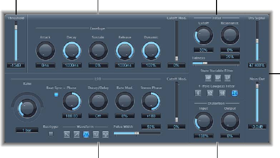
117
Filter eects overview
Filters are used to emphasize or suppress frequencies in an audio signal, resulting in a change in
the tonal color of the audio.
Logic Pro X contains a variety of advanced lter-based eects that you can use to creatively
modify your audio. These eects are most often used to radically alter the frequency spectrum of
a sound or mix.
Note: Equalizers (EQs) are special types of lters. They are not usually used as “eects” per se,
but as tools to rene the frequency spectrum of a sound or mix. See Equalizers overview on
page 104.
AutoFilter
AutoFilter overview
AutoFilter is a versatile lter eect with several unique features. You can use it to create classic,
analog-style synthesizer eects, or as a tool for creative sound design.
The eect works by analyzing incoming signal levels through use of a threshold parameter. Any
signal level that exceeds the threshold is used as a trigger for a synthesizer-style ADSR envelope
or an LFO (low frequency oscillator). These control sources are used to dynamically modulate the
lter cuto.
The AutoFilter allows you to choose between dierent lter types and slopes, control the amount
of resonance, add distortion for more aggressive sounds, and mix the original, dry signal with the
processed signal.
Filter
parameters
Threshold
parameter
Envelope
parameters
Distortion parameters
LFO parameters
Output
parameters
Filter eects 6
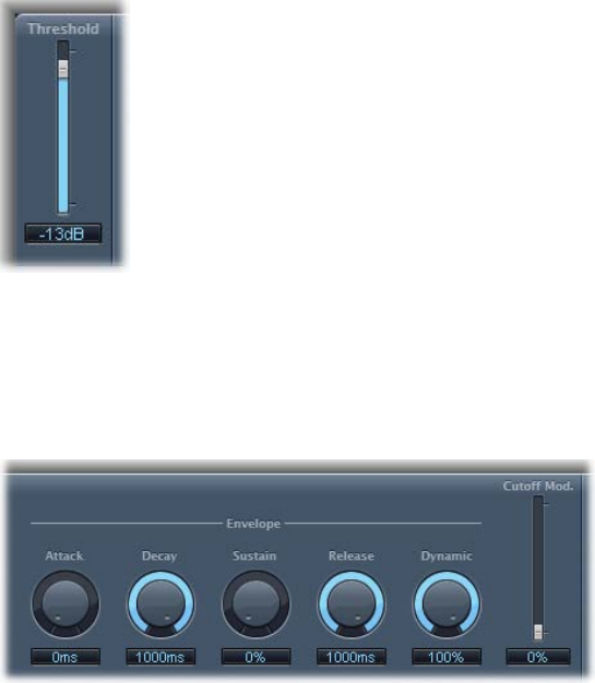
Chapter 6 Filter eects 118
The main areas of the AutoFilter window are the Threshold, Envelope, LFO, Filter, Distortion, and
Output parameter sections.
•Threshold slider: Sets an input level that—if exceeded—triggers the envelope or LFO that
dynamically modulates lter cuto frequency. See AutoFilter threshold on page 118 .
•Envelope parameters: Dene how the lter cuto frequency is modulated over time. See
AutoFilter envelope on page 118 .
•LFO parameters: Dene how the lter cuto frequency is modulated by the LFO. See AutoFilter
LFO on page 119 .
•Filter parameters: Control the tonal color of the ltered sound. See AutoFilter lter on page 120 .
•Distortion parameters: Distort the signal both before and after the lter. See AutoFilter
distortion on page 121.
•Output parameters: Set the level of both the dry and eect signal. See AutoFilter output on
page 121.
AutoFilter threshold
The Threshold parameter analyzes the level of the input signal. If the input signal level exceeds
the set threshold level, the envelope and LFO are retriggered.
Note: Retriggering of the envelope or LFO occurs only if the Retrigger button is active.
You can use the envelope and LFO to modulate the lter cuto frequency.
AutoFilter envelope
The envelope is used to shape the lter cuto over time. When the input signal exceeds the set
threshold level, the envelope is triggered.
Envelope parameters
•Attack knob and eld: Rotate to set the attack time for the envelope.
•Decay knob and eld: Rotate to set the decay time for the envelope.
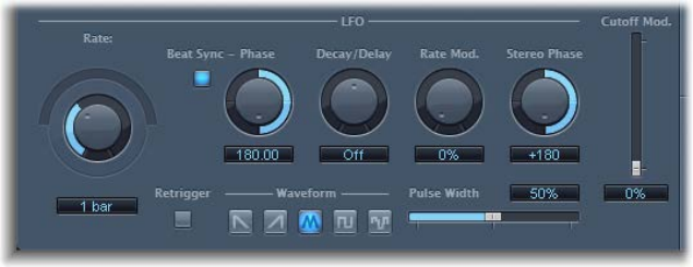
Chapter 6 Filter eects 119
•Sustain knob and eld: Rotate to set the sustain time for the envelope. If the input signal falls
below the threshold level before the envelope sustain phase, the release phase is triggered.
•Release knob and eld: Rotate to set the release time for the envelope. This is triggered as soon
as the input signal falls below the threshold.
•Dynamic knob and eld: Rotate to determine the input signal modulation amount. You can
modulate the peak value of the envelope section by varying this control.
•Cuto Mod. slider and eld: Drag to determine the impact of the envelope on the
cuto frequency.
AutoFilter LFO
The LFO is used as a modulation source for lter cuto.
LFO parameters
•Coarse Rate slider and eld: Drag to set the speed of LFO modulation. Use to set the LFO
frequency in hertz.
Note: The labels shown for the Rate knob, slider, and eld change when you activate Beat
Sync. Only the Rate knob and eld are then available.
•Fine Rate knob: Rotate to set the speed of LFO modulation. Use to ne-tune the LFO frequency.
•Beat Sync button: Turn on to synchronize the LFO to the host application tempo. You can
choose from bar values, triplet values, and more by using the Rate knob and eld.
•Phase knob and eld: Rotate to set the phase relationship between the LFO rate and the host
application tempo—when Beat Sync is active. This parameter is dimmed when Beat Sync
is disabled.
•Decay/Delay knob and eld: Rotate to set the time it takes for the LFO to go from 0 to its
maximum value.
•Rate Mod. knob and eld: Rotate to set the LFO frequency, independent of the input signal
level. Typically, when the input signal exceeds the threshold, the modulation width of the LFO
increases from 0 to the Rate Mod. value. This parameter allows you to override this behavior.
•Stereo Phase knob and eld: Rotate to set the phase relationship of the LFO modulations
between the two channels (stereo only).
•Cuto Mod. slider and eld: Drag to determine the impact of the LFO on the cuto frequency.
•Retrigger button: Turn on to start the LFO waveform at 0 each time the threshold is exceeded.
•Waveform buttons: Click to select the shape of the LFO waveform: descending sawtooth,
ascending sawtooth, triangle, pulse wave, or random.
•Pulse Width slider and eld: Drag to alter the curve shape of the selected waveform.
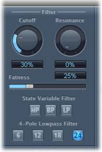
Chapter 6 Filter eects 12 0
AutoFilter lter
The Filter parameters allow you to precisely tailor the tonal color.
Filter parameters
•Cuto knob and eld: Rotate to set the cuto frequency for the lter. Higher frequencies are
attenuated, whereas lower frequencies are allowed to pass through in a lowpass lter. The
reverse is true in a highpass lter. When the State Variable Filter is set to bandpass (BP) mode,
the lter cuto determines the center frequency of the frequency band that is allowed to pass.
•Resonance knob and eld: Rotate to boost or cut signals in the frequency band that surrounds
the cuto frequency. Very high Resonance values cause the lter to begin oscillating at the
cuto frequency. This self-oscillation occurs before you reach the maximum Resonance value.
•Fatness slider and eld: Drag to boost the level of low frequency content. When you set Fatness
to its maximum value, adjusting Resonance has no eect on frequencies below the cuto
frequency. This parameter is used to compensate for a weak or “brittle” sound caused by high
resonance values, when in the lowpass lter mode.
•State Variable Filter buttons: Switch the lter between highpass (HP), bandpass (BP), or lowpass
(LP) modes.
•4-Pole Lowpass Filter buttons: Click to set the slope of the lowpass lter to 6, 12, 18, or 24 dB
per octave.
Note: Clicking one of these buttons automatically chooses the lowpass (LP) lter and slope,
overriding any active State Variable Filter button.
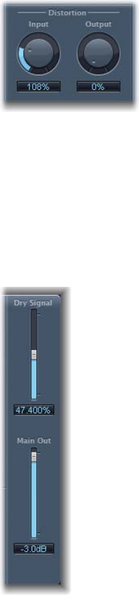
Chapter 6 Filter eects 121
AutoFilter distortion
The Distortion parameters can be used to overdrive the lter input or lter output. The distortion
input and output modules are identical, but their dierent positions in the signal chain—before
and after the lter, respectively—result in remarkably dissimilar sounds.
Distortion parameters
•Input knob and eld: Rotate to set the amount of distortion applied before the lter section
processes the signal.
•Output knob and eld: Rotate to set the amount of distortion applied after the lter section
processes the signal.
AutoFilter output
The Output parameters are used to set the wet/dry balance and overall level.
Output parameters
•Dry Signal slider and eld: Drag to set the amount of original, dry signal added to the
ltered signal.
•Main Out slider and eld: Drag to set the overall output level. This enables you to compensate
for higher levels caused by the use of distortion or by the ltering process itself.
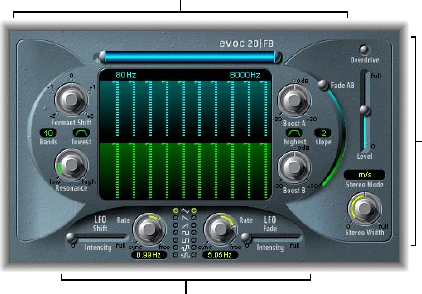
Chapter 6 Filter eects 12 2
EVOC 20 Filterbank
EVOC 20 Filterbank overview
EVOC 20 Filterbank consists of two formant lter banks. The input signal passes through the two
lter banks in parallel. Each bank features level faders for up to 20 frequency bands, allowing
independent level control of each band. Setting a level fader to its minimum value completely
suppresses the formants in that band. You can control the position of the lter bands with the
Formant Shift parameter. You can also crossfade between the two lter banks.
The EVOC 20 Filterbank interface is divided into three main sections: the Formant Filter
parameters section in the center of the window, the Modulation parameters section at the
bottom, and the Output parameters section along the right side.
Output
parameters
Formant Filter parameters
Modulation parameters
•Formant Filter parameters: Control the frequency bands in the two lter banks—the upper,
blue, lter bank A and the lower, green, lter bank B. See EVOC 20 Filterbank Formant Filter on
page 123.
•Modulation parameters: Control how Formant Filter parameters are modulated. See EVOC 20
Filterbank modulation on page 124 .
•Output parameters: Control the overall output level and panning of the EVOC 20 Filterbank. See
EVOC 20 Filterbank output parameters on page 125.
A short introduction to formants
A formant is a peak in the frequency spectrum of a sound. In the context of human voices,
formants are the key component that enables humans to distinguish between dierent vowel
sounds, based purely on the frequency of these sounds. Formants in human speech and singing
are produced by the vocal tract, with most vowel sounds containing four or more formants.
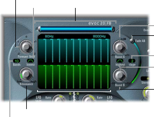
Chapter 6 Filter eects 12 3
EVOC 20 Filterbank Formant Filter
The parameters in this section provide precise level and frequency control of the lters.
Bands value field
Lowest button
Formant Shift knob
High and Low
Frequency parameters
Frequency band faders
Boost A knob
Fade AB slider
Boost B knob
Highest button
Slope pop-up menu
Resonance knob
Formant Filter parameters
•High and Low Frequency parameters: Drag to determine the lowest and highest frequencies
allowed to pass by the lter banks. Frequencies that fall outside these boundaries will be cut.
•The length of the horizontal blue bar at the top represents the frequency range. The
silver handles on the left and right ends of the blue bar set the Low Frequency and High
Frequency values, respectively. You can move the entire frequency range by dragging the
blue bar.
•You can also drag in the numeric elds that are below the blue bar to adjust the frequency
values separately.
•Frequency band faders: Drag to set the level of each frequency band in lter bank A—the blue
faders—or lter bank B—the green faders. You can quickly create complex level curves by
dragging horizontally, or “drawing,” across either row of faders.
•Formant Shift knob: Rotate to move all bands in both lter banks up or down the
frequency spectrum.
Note: The use of Formant Shift can result in the generation of unusual resonant frequencies
when high Resonance settings are used.
•Bands value eld: Drag to set the number of frequency bands—up to 20—in each lter bank.
•Lowest button: Click to switch the lowest lter band between bandpass or highpass lter
operation. In bandpass mode, the frequencies above and below the lowest band are ignored.
In highpass mode, all frequencies below the lowest band are ltered.
•Highest button: Click to switch the highest lter band between bandpass or lowpass lter
operation. In bandpass mode, the frequencies above and below the highest band are ignored.
In lowpass mode, all frequencies above the highest band are ltered.
•Resonance knob: Rotate to determine the basic sonic character of both lter banks. High
Resonance settings emphasize the center frequency of each band and result in a sharper,
brighter character. Low settings result in a softer character.
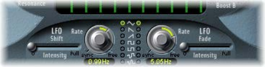
Chapter 6 Filter eects 12 4
•Boost A and Boost B knobs: Rotate to set the amount of boost—or cut—applied to the
frequency bands in lter bank A or B. You can use these knobs to compensate for the
reduction in volume caused by lowering the level of one or more bands. If you use Boost A
and Boost B to set the mix relationship between lter bank levels, you can use Fade AB (see
“Fade AB slider” below) to alter the tonal color, but not the levels.
•Slope pop-up menu: Choose the amount of lter attenuation applied to all lters in both lter
banks. You can choose 1, which sounds softer at 6 dB/octave, or 2, which sounds brighter at 12
dB/octave.
•Fade AB slider: Drag to crossfade between lter bank A and lter bank B. At the top position,
only bank A is audible, and at the bottom position, only bank B is audible. In the middle
position, the signals passing through both banks are evenly mixed.
EVOC 20 Filterbank modulation
The modulation section contains two LFOs. The Shift LFO parameters on the left side control
the Formant Shift parameter, and the Fade LFO parameters on the right side control the Fade
AB parameter.
Modulation parameters
•Shift LFO Intensity slider: Drag to set the amount of Formant Shift modulation by the Shift LFO.
•Rate knobs and elds: Rotate to set the speed of modulation. Values to the left are synchronized
with the host application tempo and include bar values, triplet values, and so on. Values to the
right are nonsynchronized, or free, and are displayed in hertz—cycles per second.
Note: The ability to use synchronous bar values could be used to perform a formant shift
every four bars on a cycled one-bar percussion part, for example. Alternatively, you could
perform the same formant shift on every eighth-note triplet within the same part. Either
method can generate interesting results.
•Waveform buttons: Click to set the waveform type used by the Shift LFO (left column) or the
Fade LFO (right column). You can choose from the following waveforms for each LFO:
•Triangle
•Falling and rising sawtooth
•Square up and down around zero (bipolar, good for trills)
•Square up from zero (unipolar, good for changing between two denable pitches)
•Random stepped waveform (S&H)
•Smoothed random waveform
•Fade LFO Intensity slider: Drag to control the amount of Fade AB modulation by the Fade LFO.
Tip: LFO modulations are the key to interesting eects. Set up either completely dierent or
complementary lter curves in both lter banks. You can use rhythmic material—such as a
drum loop—as an input signal, and set up tempo-synchronized modulations, with dierent
rates for each LFO. Also try inserting a tempo-synchronized delay eect—such as Tape
Delay—after the EVOC 20 Filterbank to produce unique polyrhythms.
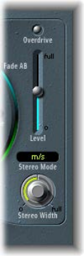
Chapter 6 Filter eects 12 5
EVOC 20 Filterbank output parameters
The output parameters provide control over the level and stereo width. The output section also
incorporates an integrated overdrive (distortion) circuit.
Output parameters
•Overdrive button: Click to turn the overdrive circuit on or o.
Note: To hear the overdrive eect, you might need to boost the level of one or both
lter banks.
•Level slider: Drag to set the volume of the output signal.
•Stereo Mode pop-up menu: Choose the input/output mode.
•In s/s mode (stereo input/stereo output), the left and right channels are processed by
separate lter banks.
•In m/s mode (mono input/stereo output), a stereo input signal is rst summed to mono
before being routed to the lter banks.
•Stereo Width knob: Rotate to distribute the output signals of the lter bands in the stereo eld.
•At the 0 position to the left, the outputs of all bands are centered.
•At the centered position at the top, the outputs of all bands ascend from left to right.
•At the full position to the right, the bands are output to the left and right
channels alternately.
Chapter 6 Filter eects 12 6
EVOC 20 TrackOscillator
EVOC 20 TrackOscillator overview
EVOC 20 TrackOscillator is a vocoder with a monophonic pitch tracking oscillator. The tracking
oscillator tracks, or follows, the pitch of a monophonic input signal. If the input signal is a
sung vocal melody, the individual note pitches are tracked and mirrored, or played, by the
synthesis engine.
EVOC 20 TrackOscillator features two formant lter banks, an analysis bank, and a synthesis lter
bank. Each oers multiple input options.
You can capture an analysis signal source by using the audio arriving at the input of the channel
strip that EVOC 20 TrackOscillator is inserted into or by using a side-chained signal from another
channel strip.
The synthesis source can be derived from the audio input of the channel strip that EVOC 20
TrackOscillator is inserted into, a side chain signal, or the tracking oscillator.
Because you can select both the analysis and synthesis input signals, EVOC 20 TrackOscillator
is not limited to pitch tracking eects; you can also use it for unusual lter eects. For example,
you could lter an orchestral recording on one channel strip with train noises side-chained from
another channel strip. Or you could use it to process drum loops with side-chained signals, such
as other drum loops or rhythmic guitar, clavinet, and piano parts.
Vocoder overview
The word vocoder is an abbreviation for voice encoder. A vocoder analyzes and transfers the sonic
character of the audio signal arriving at its analysis input to the synthesizer’s sound generators.
The result of this process is heard at the output of the vocoder.
The classic vocoder sound uses speech as the analysis signal and a synthesizer sound as the
synthesis signal. This sound was popularized in the late 1970s and early 1980s. You may be
familiar with tracks such as “O Superman” by Laurie Anderson, “Funkytown” by Lipps Inc., and
numerous Kraftwerk pieces—such as “Autobahn,” “Europe Endless,” “The Robots,” and “Computer
World.”
In addition to these “singing robot” sounds, vocoding has also been used in many lms—such as
with the Cylons in Battlestar Galactica, and most famously, with the voice of Darth Vader from the
Star Wars saga.
Vocoding, as a process, is not strictly limited to vocal performances. You could use a drum loop as
the analysis signal to shape a string ensemble sound arriving at the synthesis input.
The speech analyzer and synthesizer features of a vocoder are two bandpass lter banks.
Bandpass lters allow a frequency band—a slice in the overall frequency spectrum—to pass
through unchanged. Frequencies that fall outside the band are cut.
In the EVOC 20 plug-ins, these lter banks are named the analysis and synthesis banks. Each lter
bank has a matching number of corresponding bands—if the analysis lter bank has ve bands
(1, 2, 3, 4, and 5), there will be a corresponding set of ve bands in the synthesis lter bank. Band
1 in the analysis bank is matched to band 1 in the synthesis bank, band 2 to band 2, and so on.
The audio signal arriving at the analysis input passes through the analysis lter bank, where it is
divided into bands.
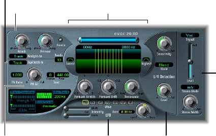
Chapter 6 Filter eects 12 7
An envelope follower is coupled to each lter band. The envelope follower of each band tracks,
or follows, volume changes in the audio source—or, more specically, the portion of the audio
that has been allowed to pass by the associated bandpass lter. In this way, the envelope
follower of each band generates dynamic control signals.
These control signals are then sent to the synthesis lter bank—where they control the levels of
the corresponding synthesis lter bands. This is done with voltage-controlled ampliers (VCAs)
in analog vocoders. Volume changes to the bands in the analysis lter bank are imposed on the
matching bands in the synthesis lter bank. These lter level changes are heard as a synthetic
reproduction of the original input signal—or a mix of the two lter bank signals.
EVOC 20 TrackOscillator interface
EVOC 20 TrackOscillator is divided into a number of parameter sections.
LFO
parameters
Analysis In parameters
U/V Detection
parameters
Formant Filter parameters
Output
parameters
Synthesis In parameters
Tracking Oscillator
parameters
•Analysis In parameters: Determine how the input signal is analyzed and used by the analysis
lter bank. See EVOC 20 TrackOscillator analysis in parameters on page 128 .
•U/V Detection parameters: Detect the unvoiced portions of the sound in the analysis signal,
improving speech intelligibility. See EVOC 20 TrackOscillator U/V detection parameters on
page 129.
•Synthesis In parameters: Determine how the input signal is used by the synthesis lter bank.
See EVOC 20 TrackOscillator synthesis in parameters on page 131.
•Tracking Oscillator parameters: Determine how the analysis input signal is used by the oscillator.
See Tracking oscillator parameters on page 131.
•Formant Filter parameters: Congure the analysis and synthesis lter banks. See EVOC 20
TrackOscillator formant lter on page 133.
•LFO parameters: Modulate either the oscillator pitch or the Formant Shift parameter. See
EVOC 20 TrackOscillator modulation on page 134 .
•Output parameters: Congure the output signal of the EVOC 20 TrackOscillator. See EVOC 20
TrackOscillator output parameters on page 135.
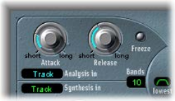
Chapter 6 Filter eects 12 8
EVOC 20 TrackOscillator analysis in parameters
The parameters in the Analysis In section determine how the input signal is analyzed and used
by the EVOC 20 TrackOscillator.
Analysis In parameters
•Attack knob: Rotate to determine how quickly each envelope follower—coupled to each
analysis lter band—reacts to rising signals.
•Release knob: Rotate to determine how quickly each envelope follower—coupled to each
analysis lter band—reacts to falling signals.
•Freeze button: Turn on to hold—or freeze—the current analysis sound spectrum indenitely.
When Freeze is enabled, the analysis lter bank ignores the input source, and the Attack and
Release knobs have no eect.
•Bands eld: Drag to set the number of frequency bands analyzed and then used by the
synthesis engine. Up to 20 bands can be used.
•Analysis In pop-up menu: Choose the analysis signal source:
•Track: Uses the input audio signal of the channel strip the EVOC 20 TrackOscillator is inserted
into as the analysis signal.
•SideCh(ain): Uses a side chain as the analysis signal. You choose the side-chain source
channel strip from the Side Chain pop-up menu in the upper-right corner of the
plug-in window.
Note: If Side Chain is chosen and no Side Chain channel strip is assigned, the EVOC 20
TrackOscillator reverts to Track mode.
Use EVOC 20 TrackOscillator analysis in
You should be precise with the Analysis In parameters in order to attain the best possible
speech intelligibility and the most accurate tracking. Follow these tasks and tips to obtain the
best results.
Set Attack and Release times
mRotate the Attack and Release knobs to set times that provide the most articulated sound.
Longer attack times result in a slower tracking response to transients—level spikes—of the
analysis input signal. A long attack time on percussive input signals, such as a spoken word
or hi-hat part, translates into a less articulated vocoder eect. Set the Attack parameter to the
lowest possible value to enhance articulation.
Longer release times cause the analysis input signal transients to sustain for a longer period at
the vocoder’s output. A long release time on percussive input signals, such as a spoken word
or hi-hat part, translates into a less articulated vocoder eect. Use of extremely short release
times results in rough, grainy vocoder sounds. Release values of around 8 to 10 ms are useful
starting points.
Chapter 6 Filter eects 12 9
Freeze the input signal
mClick the Freeze button to hold, or sustain, the sound spectrum of the analysis input signal.
By freezing the input signal you can capture a particular characteristic of the signal, which is then
imposed as a complex sustained lter shape on the Synthesis section. Here are some examples
of when this could be useful:
•If you are using a spoken word pattern as a source, the Freeze button could capture the attack
or tail phase of an individual word within the pattern—the vowel a, for example.
•People cannot sustain sung notes indenitely. To compensate for this human limitation,
use the Freeze button. If the synthesis signal needs to be sustained but the analysis source
signal—a vocal part—is not sustained, use the Freeze button to lock the current formant
levels of a sung note, even during gaps in the vocal part, between words in a vocal phrase.
Tip: The Freeze parameter can be automated, which may be useful in this situation.
Set the number of lter bank bands
mVertically drag the Bands eld to set the number of frequency bands the
EVOC 20 TrackOscillator’s lter bank uses.
The greater the number of frequency bands, the more precisely the sound can be reshaped. As
the number of bands is reduced, the source signal’s frequency range is divided up into fewer
bands, and the resulting sound will be formed with less precision by the synthesis engine. You
may nd that a good compromise between sonic precision—allowing incoming signals such as
speech and vocals to remain intelligible—and resource usage is around 10 to 15 bands.
Tip: To ensure the best possible pitch tracking, it is essential to use a mono signal with no
overlapping pitches. Ideally, the signal should be unprocessed and free of background noises.
Using a signal processed with even a slight amount of reverb, for example, can produce unusual
results. Processing a signal with no audible pitch, such as drum loop, also delivers unusual results,
but the resulting artifacts might be perfect for your project.
EVOC 20 TrackOscillator U/V detection parameters
Human speech consists of a series of voiced sounds—tonal sounds or formants—and unvoiced
sounds. The main distinction between voiced and unvoiced sounds is that voiced sounds
are produced by an oscillation of the vocal cords, whereas unvoiced sounds are produced by
blocking and restricting the air ow with lips, tongue, palate, throat, and larynx.
If speech containing voiced and unvoiced sounds is used as a vocoder’s analysis signal but the
synthesis engine doesn’t dierentiate between voiced and unvoiced sounds, the result sounds
rather weak. To avoid this problem, the synthesis section of the vocoder must produce dierent
sounds for the voiced and unvoiced parts of the signal.
EVOC 20 TrackOscillator includes an Unvoiced/Voiced detector. This unit detects the unvoiced
portions of the sound in the analysis signal and then substitutes the corresponding portions
in the synthesis signal with noise, with a mixture of noise and synthesizer signal, or with the
original signal. If the U/V Detector detects voiced parts, it passes this information to the synthesis
section, which uses the normal synthesis signal for these portions.
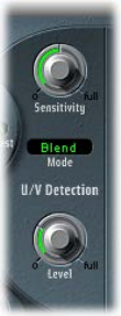
Chapter 6 Filter eects 13 0
A short introduction to formants
A formant is a peak in the frequency spectrum of a sound. In the context of human voices,
formants are the key component that enables humans to distinguish between dierent vowel
sounds—based purely on the frequency of the sounds. Formants in human speech and singing
are produced by the vocal tract, with most vowel sounds containing four or more formants.
U/V detection parameters
•Sensitivity knob: Rotate to determine how responsive U/V detection is. Turn to the right for
higher settings, where more of the individual unvoiced portions of the input signal are
recognized. When high settings are used, the increased sensitivity to unvoiced signals can
lead to the U/V sound source being used on the majority of the input signal, including voiced
signals. Sonically, this results in a sound that resembles a radio signal that is breaking up and
contains a lot of static, or noise. (The U/V sound source is determined by the Mode menu, as
described below.)
•Mode menu: Choose the sound sources used to replace the unvoiced content of the
input signal.
•Noise: Uses noise alone for the unvoiced portions of the sound.
•N + Syn (Noise + Synthesizer): Uses noise and the synthesizer for the unvoiced portions of
the sound.
•Blend: Uses the analysis signal after it has passed through a highpass lter for the unvoiced
portions of the sound. The Sensitivity parameter has no eect when this setting is used.
•Level knob: Rotate to set the volume of the signal used to replace the unvoiced content of the
input signal.
Important: Be careful with the Level knob, particularly when using a high Sensitivity value, to
avoid internally overloading the EVOC 20 TrackOscillator.
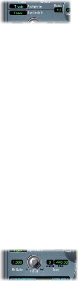
Chapter 6 Filter eects 131
EVOC 20 TrackOscillator synthesis in parameters
The Synthesis In section controls various aspects of the tracking signal for the synthesizer. The
tracking signal is used to trigger the internal synthesizer.
Synthesis in parameters
•Synthesis In pop-up menu: Choose the tracking signal source:
•Track: Uses the input audio signal of the channel strip that EVOC 20 TrackOscillator is
inserted into as the synthesis signal, which drives the internal synthesizer.
•SideCh (SideChain): Uses a side chain as the synthesis signal. You choose the side-chain
source channel from the Side Chain pop-up menu in the upper-right corner of the EVOC 20
TrackOscillator window.
•Osc. (Oscillator): Sets the tracking oscillator as the synthesis source. The oscillator mirrors, or
tracks, the pitch of the analysis input signal. Choosing Osc activates the other parameters in
the synthesis section. If Osc is not chosen, the FM Ratio, FM Int, and other parameters in this
section have no eect.
Note: If you choose Side Chain and no Side Chain channel is assigned, EVOC 20 TrackOscillator
reverts to Track mode.
•Bands eld: Drag to set the number of frequency bands analyzed and then used by the
synthesis engine.
EVOC 20 TrackOscillator oscillators
Tracking oscillator parameters
The tracking oscillator follows the pitch of incoming monophonic audio signals and mirrors
these pitches with a synthesized sound. The FM tone generator for the tracking oscillator consists
of two oscillators, each of which generates a sine wave. The frequency of Oscillator 1, the carrier,
is modulated by Oscillator 2, the modulator, which deforms the sine wave of Oscillator 1. This
results in a waveform with rich harmonic content.
Important: The parameters discussed in this section are available only if the Synthesis In menu is
set to Osc. See EVOC 20 TrackOscillator synthesis in parameters.
Tracking oscillator parameters
•FM Ratio eld: Drag to set the ratio between Oscillators 1 and 2, which denes the basic
character of the sound. Even-numbered values or their multiples produce harmonic sounds,
whereas odd-numbered values or their multiples produce inharmonic, metallic sounds.
•An FM Ratio of 1.000 produces results resembling a sawtooth waveform.
•An FM Ratio of 2.000 produces results resembling a square wave with a pulse width of 50%.
•An FM Ratio of 3.000 produces results resembling a square wave with a pulse width of 33%.
•FM Int knob: Rotate to determine the intensity of modulation. Higher values result in a more
complex waveform with more overtones.
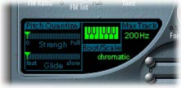
Chapter 6 Filter eects 13 2
•At a value of 0, the FM tone generator is disabled and a sawtooth wave is generated.
•At values above 0, the FM tone generator is activated. Higher values result in a more
complex and brighter sound.
•Coarse Tune eld: Drag to set the pitch oset of the oscillator in semitones.
•Fine Tune eld: Drag to set the pitch oset in cents. One cent equals 1/100 of a semitone.
Use tracking oscillator pitch parameters
The tracking oscillator pitch parameters control the automatic pitch correction feature of the
tracking oscillator. They can be used to constrain the pitch of the tracking oscillator to a scale
or chord. This allows subtle or strong pitch corrections and can be used creatively on unpitched
material with high harmonic content, such as cymbals and high-hats.
Tracking oscillator pitch parameters
•Pitch Quantize Strength slider: Drag to determine how pronounced the automatic pitch
correction is.
•Pitch Quantize Glide slider: Drag to set the amount of time pitch correction takes, allowing
sliding transitions to quantized pitches.
•Root/Scale keyboard: Click notes to dene the pitch or pitches that the tracking oscillator is
quantized to.
•Root/Scale pop-up menu: Click below Scale to choose the scale that the tracking oscillator is
quantized to.
Note: There are two discrete elds available for this parameter—Root and Scale. The Root
(key) can be changed independently of the scale chosen in the pop-up menu.
•Max Track eld: Drag to set the highest frequency. All frequencies above this threshold are cut,
making pitch detection more robust. If pitch detection produces unstable results, reduce this
parameter to the lowest possible setting that allows all appropriate input signals to be heard
or processed.
Choose a root or scale
1 Click the green value eld under Scale to open the pop-up menu.
2 Choose the scale or chord you want to use as the basis for pitch correction.
Note: You can also set the root key of the chosen scale or chord by vertically dragging the Root
(key) eld, or by double-clicking the root note and entering a root key between C and B. The
Root parameter is not available when the Root/Scale value is set to “chromatic” or “user.”
Add notes to, or remove notes from, the chosen scale or chord
mTo add notes to the scale or chord: Click unused keys on the small keyboard to highlight them
in green.
mTo remove notes from the scale or chord: Click selected notes, which then are no
longer highlighted.
Tip: Your last edit is remembered. If you choose a new scale or chord but do not make any
changes, you can revert to the previously set scale by choosing “user” from the Root/Scale
pop-up menu.
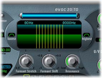
Chapter 6 Filter eects 133
EVOC 20 TrackOscillator formant lter
EVOC 20 TrackOscillator features two formant lter banks—one for the Analysis In section and
one for the Synthesis In section. The entire frequency spectrum of an incoming signal is analyzed
by the Analysis section and is divided equally into a number of frequency bands. Each lter bank
can control up to 20 of these frequency bands.
The Formant Filter display is divided in two by a horizontal line. The upper half applies to the
analysis section and the lower half to the synthesis section. Parameter changes are reected in
the Formant Filter display, thus providing feedback on what is happening to the signal as it is
routed through the two formant lter banks.
Formant lter parameters
•Low and High Frequency parameters: Drag to determine the lowest and highest frequencies
allowed to pass by the lter section. Frequencies that fall outside these boundaries are cut.
•The length of the horizontal blue bar at the top represents the frequency range for both
analysis and synthesis—unless Formant Stretch or Formant Shift is used. You can move the
entire frequency range by dragging the blue bar. The silver handles on either end of the blue
bar set the Low Frequency and High Frequency values, respectively.
•You can also drag in the numeric elds to adjust the frequency values separately.
•Lowest button: Click to switch the lowest lter band between bandpass or highpass lter
operation. In bandpass mode, the frequencies above and below the lowest band are ignored.
In highpass mode, all frequencies below the lowest band are ltered.
•Highest button: Click to switch the highest lter band between bandpass or lowpass lter
operation. In bandpass mode, the frequencies above and below the highest band are ignored.
In lowpass mode, all frequencies above the highest band are ltered.
•Formant Stretch knob: Rotate to change the width and distribution of all bands in the synthesis
lter bank. This can be a broader or narrower frequency range than that dened by the High
and Low Frequency parameters.
When Formant Stretch is set to 0, the width and distribution of the bands in the synthesis lter
bank at the bottom match the width of the bands in the analysis lter bank at the top. Low
values narrow the width of each band in the synthesis bank, whereas high values widen the
bands. The control range is expressed as a ratio of the overall bandwidth.
•Formant Shift knob: Rotate to move all bands in the synthesis lter bank up or down the
frequency spectrum.
When Formant Shift is set to 0, the positions of the bands in the synthesis lter bank match
the positions of the bands in the analysis lter bank. Positive values move the synthesis lter
bank bands up in frequency, whereas negative values move them down—in relation to the
analysis lter bank band positions.
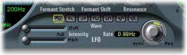
Chapter 6 Filter eects 13 4
When combined, Formant Stretch and Formant Shift alter the formant structure of the
resulting vocoder sound, which can lead to interesting timbre changes. For example, using
speech signals and tuning Formant Shift up results in “Mickey Mouse” eects.
Formant Stretch and Formant Shift are also useful if the frequency spectrum of the synthesis
signal does not complement the frequency spectrum of the analysis signal. You could create a
synthesis signal in the high-frequency range from an analysis signal that mainly modulates the
sound in a lower-frequency range, for example.
Note: Use of the Formant Stretch and Formant Shift parameters can result in the generation of
unusual resonant frequencies when high Resonance settings are used.
•Resonance knob: Rotate to change the basic sonic character of the vocoder. Low settings result
in a soft character, whereas high settings lead to a more snarling, sharp character. Technically,
increasing the Resonance value emphasizes the middle frequency of each frequency band.
EVOC 20 TrackOscillator modulation
The parameters in this section control the LFO, which can be used to modulate either the pitch
of the tracking oscillator, thus creating a vibrato, or the Formant Shift parameter of the synthesis
lter bank.
Modulation parameters
•Shift Intensity slider: Drag to set the amount of formant shift modulation by the LFO.
•Pitch Intensity slider: Drag to set the amount of pitch modulation—vibrato—by the LFO.
•Waveform buttons: Click to set the waveform type used by the LFO. You can choose from the
following waveforms:
•Triangle
•Falling and rising sawtooth
•Square up and down around zero (bipolar, good for trills)
•Square up from zero (unipolar, good for changing between two denable pitches)
•Random stepped waveform (S&H)
•Smoothed random waveform
•LFO Rate knob and eld: Rotate to set the speed of modulation. Values to the left are
synchronized with the host application tempo and include bar values, triplet values, and so on.
Values to the right are nonsynchronized, or free, and are displayed in hertz—cycles per second.
Note: The ability to use synchronous bar values could be used to perform a formant shift
every four bars on a cycled one-bar percussion part, for example. Alternatively, you could
perform the same formant shift on every eighth-note triplet within the same part. Either
method can generate interesting results.
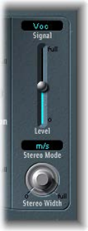
Chapter 6 Filter eects 13 5
EVOC 20 TrackOscillator output parameters
The output section provides control over the type, stereo width, and level of signal that is sent
from the EVOC 20 TrackOscillator.
Output parameters
•Signal pop-up menu: Choose the signal that is sent to the plug-in’s main outputs:
•Voc(oder): Hear the vocoder eect.
•Syn(thesis): Hear only the synthesizer signal.
•Ana(lysis): Hear only the analysis signal.
Note: The last two settings are mainly useful for monitoring purposes.
•Level slider: Drag to set the overall volume of the output signal.
•Stereo Mode pop-up menu: Choose the input/output mode.
•In s/s mode (stereo input/stereo output), the left and right channels are processed by
separate lter banks.
•In m/s mode (mono input/stereo output), a stereo input signal is rst summed to mono
before being routed to the lter banks.
•Stereo Width knob: Rotate to distribute the output signals of the synthesis section’s lter bands
in the stereo eld.
•At the 0 position to the left, the outputs of all bands are centered.
•At the centered position, the outputs of all bands ascend from left to right.
•At the Full position to the right, the bands are output—alternately—to the left and
right channels.
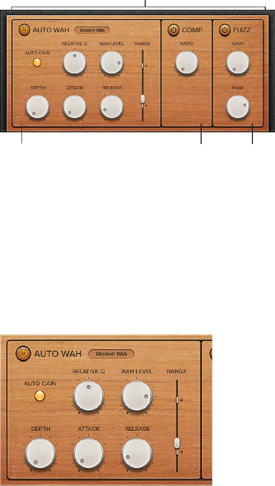
Chapter 6 Filter eects 13 6
Fuzz-Wah
Fuzz-Wah overview
The Fuzz-Wah plug-in emulates classic wah eects, combined with compression and fuzz
distortion eects. The name wah wah comes from the sound it produces. It has been a popular
eect—usually a pedal eect—with electric guitarists since the days of Jimi Hendrix. The pedal
controls the cuto frequency of a bandpass, a lowpass, or—less commonly—a highpass lter.
Wah parameters Fuzz parameters
Drag a panel to
determine the order of
the effects chain.
Compressor parameters
Fuzz-Wah eects work in series—where the output of one eect is fed into the next in an eects
chain. The routing order lets you choose whether a distorted signal should be wah-ltered
(for funkier sounds) or the wah-ltered sound should be distorted (for screaming sounds)—as
an example.
Horizontally drag the name of the eect to determine the order of the eects chain.
Auto Wah parameters
These parameters determine the tone and behavior of the wah eect.
You can control the wah eect with the Auto Wah feature, which continually performs a lter
sweep across the entire range. You can also control the wah sweep with MIDI foot pedals or
other controllers.
Auto Wah parameters
•On/o button: Turns the Auto Wah eect on or o.
•Wah Type pop-up menu: Choose a Wah eect type.
Chapter 6 Filter eects 137
•Classic Wah: This setting mimics the sound of a popular wah pedal with a slight
peak characteristic.
•Retro Wah: This setting mimics the sound of a popular vintage wah pedal.
•Modern Wah: This setting mimics the sound of a distortion wah pedal with a constant
Q(uality) Factor setting. The Q determines the resonant characteristics. Low Q values aect
a wider frequency range, resulting in softer resonances. High Q values aect a narrower
frequency range, resulting in more pronounced emphasis.
•Opto Wah 1: This setting mimics the sound of a distortion wah pedal with a constant
Q(uality) Factor setting.
•Opto Wah 2: This setting mimics the sound of a distortion wah pedal with a constant
Q(uality) Factor setting.
•Resonant LP: In this mode, the Wah works as a resonance-capable lowpass lter. At the
minimum pedal position, only low frequencies can pass.
•Resonant HP: In this mode, the Wah works as a resonance-capable highpass lter. At the
maximum pedal position, only high frequencies can pass.
•Peak: In this mode, the Wah works as a peak (bell) lter. Frequencies close to the cuto
frequency are emphasized.
•Auto Gain button: Turn on to limit the output signal dynamic range. The wah eect can cause
the output level to vary widely. Auto Gain compensates for this tendency and keeps the
output signal within a more stable range.
•Relative Q knob: Rotate to adjust the main lter peak, resulting in a sharper or softer
wah sweep.
•Wah Level knob: Rotate to set the amount of the wah-ltered signal.
•Depth knob: Rotate to set the depth of the Auto Wah eect. When set to 0, the automatic
wah feature is disabled.
•Attack knob: Rotate to set the time it takes for the wah lter to fully open.
•Release knob: Rotate to set the time it takes for the wah lter to close.
•(Pedal) Range slider: Drag to sweep the wah lter. The two smaller sliders set the maximum and
minimum values of the sweep range.
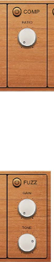
Chapter 6 Filter eects 13 8
Fuzz-Wah Compressor parameters
The Compressor eect is normally used just before the Fuzz (distortion) eect. This allows you to
increase or decrease the perceived gain, thus providing a suitable input level to the distortion
circuit. You can, however, place the Compressor at any position in the eects chain or can disable
it completely.
Compressor eect parameters
•On/o button: Turns the Compressor eect on or o.
•Ratio knob: Rotate to adjust the compression slope. The additional gain oered by
the compression circuit—when directly preceding the Fuzz eect—lets you create
crunchy distortions.
Fuzz parameters
These parameters control the integrated distortion circuit.
Fuzz parameters
•On/o button: Turns the Fuzz distortion eect on or o.
•Fuzz Gain knob:Rotate to set the level of distortion.
•Fuzz Tone knob:Rotate to adjust the tonal color of the distortion. Low settings tend to be
warmer, and high settings are brighter and harsher.
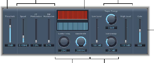
Chapter 6 Filter eects 13 9
Spectral Gate
Spectral Gate overview
Spectral Gate is an unusual lter eect that can be used as a tool for creative sound design.
It works by dividing the incoming signal into two frequency ranges—above and below a central
frequency band that you specify with the Center Freq and Bandwidth parameters. The signal
ranges above and below the dened band can be individually processed with the Low Level
and High Level parameters and the Super Energy and Sub Energy parameters. See Use Spectral
Gate on page 140.
Gain slider
Graphic
display
Center Freq. and
Bandwidth knobs
Sub Energy and
Low Level controls
Speed, CF Modulation,
and BW Modulation
sliders
Super Energy and
High Level controls
Threshold
slider
Spectral Gate parameters
•Threshold slider and eld: Drag to set the threshold level that is used to divide frequency
ranges. When the threshold is exceeded, the frequency band dened by the Center Freq and
Bandwidth parameters is divided into upper and lower frequency ranges.
•Speed slider and eld: Drag to set the modulation frequency for the dened frequency band.
•CF (center frequency) Modulation slider and eld: Drag to set the intensity of center
frequency modulation.
•BW (bandwidth) Modulation slider and eld: Drag to set the amount of bandwidth modulation.
•Graphic display: Shows the frequency band dened by the Center Freq and
Bandwidth parameters.
•Center Freq(uency) knob and eld: Rotate to set the center frequency of the band that you want
to process.
•Bandwidth knob and eld: Rotate to set the width of the frequency band that you want
to process.
•Super Energy knob and eld: Rotate to set the level of the frequency range above the threshold.
•High Level slider and eld: Drag to mix the frequencies of the original signal—above the
selected frequency band—with the processed signal.
•Sub Energy knob and eld: Rotate to set the level of the frequency range below the threshold.
•Low Level slider and eld: Drag to mix the frequencies of the original signal—below the
selected frequency band—with the processed signal.
•Gain slider and eld: Drag to set the overall output level.
Chapter 6 Filter eects 140
Use Spectral Gate
One way you can familiarize yourself with the operation of Spectral Gate is to start with a
drum loop. Set Center Freq to its minimum value (20 Hz) and Bandwidth to its maximum value
(20,000 Hz) so that the entire frequency range is processed. Turn up the Super Energy and Sub
Energy knobs, one at a time, and then try dierent Threshold settings to get a sense of how
dierent Threshold levels aect the sound of Super Energy and Sub Energy. When you have
obtained a sound that you like or consider useful, narrow the Bandwidth parameter drastically,
gradually increase Center Freq, and then use the Low Level and High Level sliders to mix in some
treble and bass from the original signal. At lower Speed settings, turn up the CF Modulation or
BW Modulation sliders.
Get started with Spectral Gate
1 Rotate the Center Freq and Bandwidth knobs to set the frequency band you want to process.
The graphic display shows the band that you dene with these two parameters.
2 Drag the Threshold slider to set the appropriate level.
All incoming signals above and below the threshold level are divided into upper and lower
frequency ranges.
3 Rotate the Super Energy knob to control the level of the frequencies above the threshold, and
rotate the Sub Energy knob to control the level of the frequencies below the threshold.
4 Drag the Low Level slider and the High Level slider to mix the frequencies that fall outside the
dened frequency band with the processed signal.
•Use the Low Level slider to blend the frequencies below the dened frequency band with the
processed signal.
•Use the High Level slider to blend frequencies above the dened frequency band with the
processed signal.
5 Drag the Speed, CF Modulation, and BW Modulation sliders to modulate the dened frequency
band.
•Use the Speed slider to determine the modulation frequency.
•Use the CF Modulation slider to dene the intensity of the center frequency modulation.
•Use the BW Modulation slider to control the amount of bandwidth modulation.
6 Drag the Gain slider to adjust the nal output level of the processed signal.
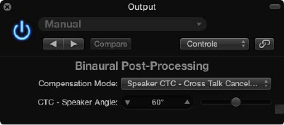
141
Imaging processors overview
The imaging processors are tools for manipulating the stereo image. You can use them to make
certain sounds, or the overall mix, seem wider and more spacious. You can also alter the phase of
individual sounds within a mix to enhance or suppress particular transients.
Binaural Post-Processing
Each channel strip in Logic Pro allows you to use a special version of the Pan knob, known as
the Binaural Panner. This is a psychoacoustic processor that can simulate arbitrary sound source
positions—including up and down information—when fed a standard stereo signal.
The output signal that results when you use Binaural Panner is best suited for headphone
playback. You can, however, use the integrated conditioning of the Binaural Panner to ensure a
neutral sound that is suitable for speaker playback as well as headphone playback.
For more information about using Binaural Panner with the Binaural Post-Processing plug-in, see
the Logic Pro User Manual.
Binaural Post-Processing parameters
•Compensation Mode pop-up menu: Choose the type of processing applied for dierent
playback systems:
•Headphone FF—optimized for front direction: For headphone playback, utilizing free-eld
compensation. In this mode, sound sources placed in front of the listening position have
neutral sound characteristics.
•Headphone HB—optimized for horizontal directions: For headphone playback, optimized to
deliver the most neutral sound for sources placed on, or close to, the horizontal plane.
•Headphone DF—averaged over all directions: For headphone playback, utilizing diuse-eld
compensation. In this mode, the sound, on average, is most neutral for arbitrarily placed, or
moved, sources.
•Speaker CTC—Cross Talk Cancelation: For speaker playback, allowing you to play back
binaurally panned signals through stereo loudspeakers. Good spatial reproduction is
restricted to a limited range of listening positions, on the symmetrical plane, between the
speakers.
Imaging processors 7
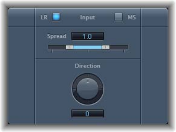
Chapter 7 Imaging processors 14 2
•CTC—Speaker Angle eld and slider: Drag to set an angle that matches the physical angle of
your stereo speakers, in relation to the listening position.
Note: This parameter is available only when the Speaker CTC compensation mode is chosen.
Use multiple Binaural Panners on several channels
1 Turn o the integrated conditioning.
2 Route the output of all binaurally panned signals to an aux channel.
3 Insert a Binaural Post-Processing plug-in into the aux channel.
4 Apply diuse-eld compensation to all Binaural Panner outputs at once.
Using multiple Binaural Panners on several channels is simpler to manage than using
a single Binaural Panner on each channel; it also sounds better and reduces computer
processing requirements.
Direction Mixer
Direction Mixer overview
You can use Direction Mixer to decode middle and side audio recordings or to spread the stereo
base of a left/right recording and determine its pan position.
Direction Mixer works with any type of stereo recording, regardless of the miking technique
used. For information about the most common stereo miking techniques—AB, XY, and MS—see
Stereo miking techniques on page 143.
Direction Mixer parameters
•Input buttons: Click to set the input signal type. Click the LR button if the input signal is a
standard left/right signal, and click the MS button if the signal is middle and side encoded.
•Spread slider and eld: Drag to determine the spread of the stereo base in LR input signals or to
set the side signal level in MS input signals. Spread parameter behavior changes when fed LR
or MS signals. These dierences are outlined below:
When you are working with LR signals:
•At a neutral value of 1, the left side of the signal is positioned precisely to the left and the
right side precisely to the right. As you decrease the Spread value, the two sides move
toward the center of the stereo image.
•A value of 0 produces a summed mono signal—both sides of the input signal are routed to
the two outputs at the same level. At values greater than 1, the stereo base is extended out
to an imaginary point beyond the spatial limits of the speakers.
Chapter 7 Imaging processors 14 3
When you are working with MS signals:
•Values of 1 or higher increase the level of the side signal, making it louder than the middle
signal.
•At a value of 2, you hear only the side signal.
•Direction knob and eld: Rotate to set the pan position for the middle—the center of the stereo
base—of the recorded stereo signal. When Direction is set to a value of 0, the midpoint of the
stereo base in a stereo recording is perfectly centered within the mix.
When you are working with LR signals:
•At 90°, the center of the stereo base is panned hard left.
•At −90°, the center of the stereo base is panned hard right.
•Higher values move the center of the stereo base back toward the center of the stereo mix,
but this also has the eect of swapping the stereo sides of the recording. For example, at
values of either 180° or −180°, the center of the stereo base is dead center in the mix, but the
left and right sides of the recording are swapped.
When you are working with MS signals:
•At 90°, the middle signal is panned hard left.
•At −90°, the middle signal is panned hard right.
•Higher values move the middle signal back toward the center of the stereo mix, but this also
has the eect of swapping the side signals of the recording. For example, at values of either
180° or −180°, the middle signal is dead center in the mix, but the left and right sides of the
side signal are swapped.
Stereo miking techniques
There are three commonly used stereo miking variations used in recording: AB, XY, and MS. A
stereo recording contains two channel signals.
AB and XY recordings both record left and right channel signals, but the middle signal is the
result of combining both channels.
MS recordings record a middle signal, but the left and right channels are decoded from the side
signal, which is the sum of both left and right channel signals.
AB miking
In an AB recording, two microphones—commonly omnidirectional, but any polarity can be
used—are equally spaced from the center and pointed directly at the sound source. Spacing
between microphones is extremely important for the overall stereo width and perceived
positioning of instruments within the stereo eld.
The AB technique is commonly used for recording one section of an orchestra, such as the
string section, or perhaps a small group of vocalists. It is also useful for recording piano or
acoustic guitar.
AB is not well suited to recording a full orchestra or group as it tends to smear the stereo
imaging/positioning of o-center instruments. It is also unsuitable for mixing down to mono
because phase cancelations can occur between channels.
Chapter 7 Imaging processors 14 4
XY miking
In an XY recording, two directional microphones are symmetrically angled from the center of the
stereo eld. The right-hand microphone is aimed at a point between the left side and the center
of the sound source. The left-hand microphone is aimed at a point between the right side and
the center of the sound source. This results in a 45° to 60° o-axis recording on each channel (or
90° to 120° between channels).
XY recordings tend to be balanced in both channels, with good positional information being
encoded. XY recording is commonly used for drum recording and is also suitable for larger
ensembles and many individual instruments.
Typically, XY recordings have a narrower sound eld than AB recordings, so they can lack a sense
of perceived width when played back. XY recordings can be mixed down to mono.
MS miking
To make a Middle and Side (MS) recording, two microphones are positioned as closely together
as possible—usually placed on a stand or hung from the studio ceiling. One is a cardioid (or
omnidirectional) microphone that directly faces the sound source you want to record—in a
straight alignment. The other is a bidirectional microphone, with its axes pointing to the left and
right of the sound source at 90° angles. The cardioid microphone records the middle signal to
one side of a stereo recording. The bidirectional microphone records the side signal to the other
side of a stereo recording. MS recordings made in this way can be decoded by the Direction
Mixer.
When MS recordings are played back, the side signal is used twice:
•As recorded
•Panned hard left and phase reversed, panned hard right
MS is ideal for all situations where you need to retain absolute mono compatibility. The
advantage of MS recordings over XY recordings is that the stereo middle is positioned on the
main recording direction (on-axis) of the cardioid microphone. This means that slight uctuations
in frequency response that occur o the on-axis—as is the case with every microphone—are less
troublesome, because the recording always retains mono compatibility.
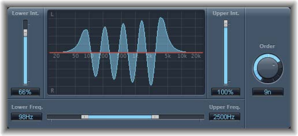
Chapter 7 Imaging processors 14 5
Stereo Spread
Stereo Spread is generally used when mastering. There are several ways to extend the stereo
base (or the perception of space), including using reverbs or other eects and altering the
signal’s phase. These options can sound good, but they can also weaken the overall sound of
your mix by ruining transient responses, for example.
Stereo Spread extends the stereo base by distributing a selectable number of frequency bands
from the middle frequency range to the left and right channels. This is done alternately—middle
frequencies to the left channel, middle frequencies to the right channel, and so on. This greatly
increases the perception of stereo width without making the sound totally unnatural, especially
when it is used on mono recordings.
Stereo Spread parameters
•Lower Int(ensity) slider and eld: Drag to set the amount of stereo base extension for the lower
frequency bands.
•Upper Int(ensity) slider and eld: Drag to set the amount of stereo base extension for the upper
frequency bands.
Note: When you are setting the Lower Int and Upper Int sliders, be aware that the stereo eect
is most apparent in the middle and higher frequencies. Distributing low frequencies between
the left and right speakers can signicantly alter the energy of the overall mix. Use low values
for the Lower Int parameter and avoid setting the Lower Freq parameter below 300 Hz.
•Graphic display: Shows the number of bands the signal is divided into and the eect intensity
in the upper and lower frequency bands. The upper section represents the left channel.
The lower section represents the right channel. The frequency scale displays frequencies in
ascending order, from left to right.
•Upper and Lower Freq(uency) slider and elds: Drag to determine the highest and lowest
frequencies that are redistributed in the stereo image.
•Order knob and eld: Rotate to determine the number of frequency bands that the signal is
divided into. A value of 8 is usually sucient for most tasks, but you can use up to 12 bands.

146
Metering tools overview
You can use the Metering tools to analyze audio in a variety of ways. These plug-ins oer you
dierent ways to view your audio than the meters shown in channel strips. The Metering plug-ins
have no eect on the audio signal and are intended for use as diagnostic aids.
Each meter is specically designed to view dierent characteristics of an audio signal, making
each suitable for particular studio situations. For example, BPM Counter displays the tempo,
Correlation Meter displays the phase relationship, and Level Meter displays the level of an
incoming audio signal.
BPM Counter
BPM Counter analyzes the tempo of incoming audio in beats per minute (bpm). The detection
circuit looks for any transients, also known as impulses, in the input signal. Transients are very
fast, non-periodic sound events in the attack portion of the signal. The more obvious this impulse
is, the easier it is for BPM Counter to detect the tempo.
Percussive drum and instrumental rhythm parts, such as basslines, are suitable for tempo
analysis, whereas pad sounds are unsuitable candidates for tempo analysis.
The LED shows the current analysis status. If the LED is ashing, a tempo measurement is taking
place. When the LED is continuously lit, analysis is complete, and the tempo is displayed. The
measurement ranges from 80 to 160 beats per minute. The measured value is displayed with an
accuracy of one decimal place. Click the LED to reset BPM Counter.
Note: BPM Counter also detects tempo variations in the signal and tries to analyze them
accurately. If the LED starts ashing during playback, this indicates that BPM Counter has
detected a tempo that has deviated from the last received (or set) tempo. As soon as a new,
constant tempo is recognized, the LED is solidly lit and the new tempo displayed.
Metering tools 8
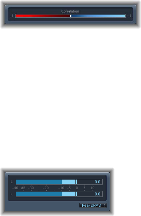
Chapter 8 Metering tools 147
Correlation Meter
Correlation Meter displays the phase relationship of a stereo signal.
•A correlation of +1 (the far right position) means that the left and right channels correlate
100%—they are completely in phase.
•A correlation of 0 (the center position) indicates the widest permissible left/right divergence,
often audible as an extremely wide stereo eect.
•Correlation values lower than 0 indicate that out-of-phase material is present, which can lead
to phase cancelations if the stereo signal is combined into a monaural signal.
Level Meter plug-in
Level Meter displays the current signal level on a decibel scale. The signal level for each channel
is represented by a blue bar. When the level exceeds 0 dB, the portion of the bar to the right of
the 0 dB point turns red.
Stereo Level Meter instances show independent left and right bars, whereas mono instances
display a single bar. Surround instances display a bar for each channel—in a vertical, rather than
horizontal, orientation.
The current peak values are displayed numerically, superimposed over the graphic display. You
can reset these values by clicking in the display.
Level Meter parameters
•Display type pop-up menu: Choose a display setting using Peak, RMS, Peak & RMS, Inter Sample
Peak, Inter Sample Peak & RMS characteristics.
The Inter Sample Peak options display inter-sample values.
RMS levels appear as dark blue bars. Peak levels appear as light blue bars. You can also choose
to view both Peak and RMS levels simultaneously.
Peak and RMS levels
The peak value is the highest level that the signal will reach. The RMS (root mean square) value
is the eective value of the total signal. In other words, it is a measurement of the continuous
power of the signal.
Human hearing is optimized for capturing continuous signals, making our ears RMS instruments,
not peak reading instruments. Therefore, using RMS meters makes sense most of the time.
Alternatively, you can use both RMS and Peak meters.
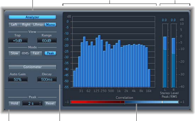
Chapter 8 Metering tools 148
MultiMeter
MultiMeter overview
MultiMeter provides a collection of professional gauge and analysis tools in a single window. It
includes:
•An Analyzer to view the level of each 1/3-octave frequency band
•A Goniometer for judging phase coherency in a stereo sound eld
•A Correlation Meter to spot mono phase compatibility
•An integrated Level Meter to view the signal level for each channel
You can view either the Analyzer or Goniometer results in the main display area. You switch the
view and set other MultiMeter parameters with the controls on the left side of the window.
Peak parameters
Analyzer
parameters
Goniometer parameters
Level Meter
Correlation Meter
Main display in
Analyzer view
Although you can insert MultiMeter directly into any channel strip, it is more commonly used in
the master channel strip of the host application—when you are working on the overall mix.
There is also a surround version of MultiMeter, with parameters for each channel and a slightly
dierent layout. See Surround MultiMeter overview on page 153.
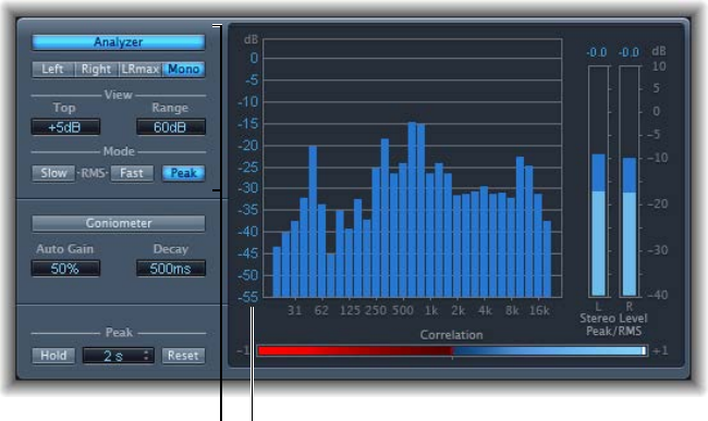
Chapter 8 Metering tools 149
MultiMeter Analyzer parameters
In Analyzer mode, MultiMeter’s main display shows the frequency spectrum of the input signal
as 31 independent frequency bands. Each frequency band represents one-third of an octave.
The Analyzer parameters are used to activate Analyzer mode and to customize the way that the
incoming signal is shown in the main display.
Analyzer parameters Scale
MultiMeter Analyzer parameters
•Analyzer button: Switches the main display to Analyzer mode.
•Left, Right, LRmax, and Mono buttons: Click to determine the channels shown in the Analyzer
results in the main display.
•Left or Right: Displays the left or right channels.
•LRmax: Displays the maximum level of the stereo inputs.
•Mono: Displays the spectrum of the mono sum of both (stereo) inputs.
•View elds: Drag to alter the way values are shown in the Analyzer by setting the maximum
level displayed (Top) and the overall dynamic range (Range).
•Mode buttons: Click to determine how levels are displayed. You can choose from Peak, Slow
RMS, or Fast RMS characteristics.
•The two RMS modes show the eective signal average and provide a representative
overview of perceived volume levels.
•The Peak mode shows level peaks accurately.
•Scale (shown in main display): Indicates the scale of levels. Drag the scale vertically to adjust.
Changing the scale is useful when you are analyzing highly compressed material because it
makes it easier to identify small level dierences.
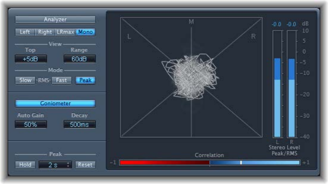
Chapter 8 Metering tools 15 0
MultiMeter Goniometer parameters
A goniometer helps you to judge the coherence of the stereo image and determine phase
dierences between the left and right channels. Phase problems are easily spotted as trace
cancelations along the center line (M—mid/mono).
The idea of the goniometer was born with the advent of early two-channel oscilloscopes. To use
such devices as goniometers, users would connect the left and the right stereo channels to the
X and Y inputs, while rotating the display by 45° to produce a useful visualization of the signal’s
stereo phase.
The signal trace slowly fades to black, imitating the retro glow of the tubes found in older
goniometers, while also enhancing the readability of the display.
MultiMeter Goniometer parameters
•Goniometer button: Switches the main display to Goniometer mode.
•Auto Gain eld: Drag to set the amount of display compensation for low input levels. You can
set Auto Gain levels in 10% increments or set it to o.
Note: To avoid confusion with the Auto Gain parameter found in other Logic Pro eects
and processors (such as the compressors), Auto Gain is only used as a display parameter in
the meters. It increases display levels to enhance readability. It does not change the actual
audio levels.
•Decay eld: Drag to determine the time it takes for the Goniometer trace to fade to black.
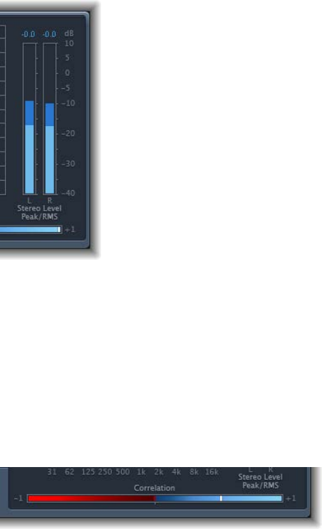
Chapter 8 Metering tools 151
MultiMeter Level Meter
The Level Meter displays the current signal level on a logarithmic decibel scale. The signal level
for each channel is represented by a blue bar.
RMS and peak levels are shown simultaneously, with RMS levels appearing as dark blue bars
and Peak levels appearing as light blue bars. When the level exceeds 0 dB, the portion of the bar
above the 0 dB mark turns red.
Current peak values are displayed numerically (in dB increments) above the Level Meter. Click in
the display to reset peak values.
MultiMeter Correlation Meter
The Correlation Meter gauges the phase relationship of a stereo signal. The Correlation Meter’s
scale values indicate the following:
•A +1 correlation value indicates that the left and right channels correlate 100%. In other words,
the left and right signals are in phase and are the same shape.
•Correlation values in the blue zone (between +1 and the middle position) indicate that the
stereo signal is mono compatible.
•The middle position indicates the highest allowable amount of left/right divergence, which is
often audible as an extremely wide stereo eect.
•When the Correlation Meter moves into the red area to the left of the center position, out-of-
phase material is present. This leads to phase cancelations if the stereo signal is combined into
a mono signal.
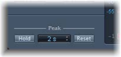
Chapter 8 Metering tools 152
MultiMeter Peak parameters
The MultiMeter Peak parameters are used to enable or disable the peak hold function and
to reset the peak segments of all meter types. You can also determine a temporary peak
hold duration.
MultiMeter Peak parameters
•Hold button: Click to turn on peak hold for all metering tools in the MultiMeter, as follows:
•Analyzer: A small yellow segment above each 1/3-octave level bar indicates the most recent
peak level.
•Goniometer: All illuminated pixels are held during a peak hold.
•Correlation Meter: The horizontal area around the white correlation indicator denotes phase
correlation deviations in real time, in both directions. A vertical red line to the left of the
correlation indicator shows the maximum negative phase deviation value. You can reset this
line by clicking it during playback.
•Level Meter: A small yellow segment above each stereo level bar indicates the most recent
peak level.
•Hold Time pop-up menu: Choose the hold time for all metering tools. Choose 2, 4, or 6
seconds—or innite.
Note: The (peak) Hold button must be turned on for the selected time value to have an eect.
•Reset button: Click to reset the peak hold segments of all metering tools.
•Inter Sample Peak Detection checkbox (Extended Parameters area): Select to detect inter-sample
peaks in the signal.
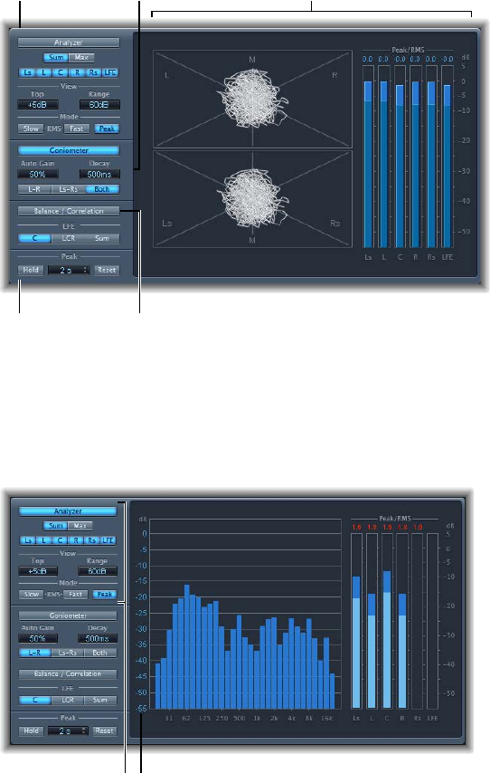
Chapter 8 Metering tools 153
Surround MultiMeter
Surround MultiMeter overview
The surround version of the MultiMeter is specically designed for analysis and metering of
multichannel surround les. You can view either the Analyzer, Goniometer, or Correlation Meter
results in the main display area. Use the controls on the left side of the window to switch the
view and set other MultiMeter parameters. The (Peak/RMS) Level Meter is visible on the right.
Although you can insert Surround MultiMeter directly into any channel strip, it is more
commonly used in the master channel strip of Logic Pro—when you are working on the overall
surround mix.
Peak parameters Balance/Correlation button
Main display
(Goniometer shown)
Goniometer
parameters
Analyzer
parameters
Surround MultiMeter Analyzer mode
In Analyzer mode, Surround Multimeter’s main display shows the frequency spectrum of the
input signal as 31 independent frequency bands. Each frequency band represents one-third of an
octave. The Analyzer parameters are used to activate Analyzer mode and to customize the way
that the incoming signal is shown in the main display.
Analyzer parameters Scale
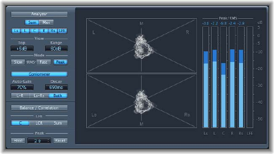
Chapter 8 Metering tools 15 4
Surround MultiMeter Analyzer parameters
•Analyzer button: Switches the main display to Analyzer mode.
•Sum and Max buttons: Click to show the summed or maximum level in the Analyzer results in
the main display. These buttons are relevant only when multiple channels are selected with
the channel buttons.
•Channel buttons: Click to select one or multiple channels for metering. The number and
appearance of these buttons vary when dierent surround output congurations are chosen.
•View elds: Alter the way that values are shown in the Analyzer by setting the maximum level
displayed (Top) and the overall dynamic range (Range).
•Mode buttons: Click to determine how levels are displayed. You can choose from Peak, Slow
RMS, or Fast RMS characteristics.
•The two RMS modes show the eective signal average and provide a representative
overview of perceived volume levels.
•The Peak mode shows level peaks accurately.
•Scale (shown in the main display): Indicates the scale of levels. Drag the scale vertically to adjust.
Changing the scale is useful when you are analyzing highly compressed material because it
makes it easier to identify small level dierences.
Surround MultiMeter Goniometer mode
A goniometer helps you to judge the coherence of the stereo image and determine phase
dierences between the left and right channels. Phase problems are easily spotted as trace
cancelations along the center line (M—mid/mono).
The idea of the goniometer was born with the advent of early two-channel oscilloscopes. To use
such devices as goniometers, users would connect the left and the right stereo channels to the
X and Y inputs, while rotating the display by 45° to produce a useful visualization of the signal’s
stereo phase. The signal trace slowly fades to black, imitating the retro glow of the tubes found
in older goniometers, while also enhancing the readability of the display.
Because the Surround MultiMeter Goniometer is dealing with multichannel signals, the
display is divided into multiple segments, as shown in the image. Each segment indicates a
speaker position. When the surround panner is moved in a channel strip, the indicator changes
accordingly. This indicates not only left and right channel coherence, but also the front-
to-rear coherence.
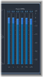
Chapter 8 Metering tools 155
Surround MultiMeter Goniometer parameters
•Goniometer button: Turn on to show the Goniometer results in the main display.
•Auto Gain eld: Drag to set the amount of display compensation for low input levels. You can
set Auto Gain levels in 10% increments, or you can turn it o.
Note: To avoid confusion with the Auto Gain parameter found in other Logic Pro eects and
processors (such as the compressors), Auto Gain is only used as a display parameter in the
meters. It increases display levels to enhance readability. It does not change audio levels.
•Decay eld: Drag to set the time it takes for the Goniometer trace to fade to black.
•L–R, Ls–Rs, and Both buttons: Click to determine the channel pairs shown in the main display.
When you are using Surround MultiMeter in congurations with exactly two channel pairs
(quad, 5.1, and 6.1 congurations), the Goniometer can display both pairs if you select Both.
One pair (for L-R) appears in the upper half of the main display, and one (for Ls-Rs) appears in
the lower half.
Surround MultiMeter Level Meter
The Level Meter displays the current signal level on a logarithmic decibel scale. The signal level
for each channel is represented by a blue bar.
RMS and Peak levels are shown simultaneously, with RMS levels appearing as dark blue bars,
and Peak levels appearing as light blue bars. When the level exceeds 0 dB, the portion of the bar
above the 0 dB mark turns red.
Current peak values are displayed numerically (in dB increments) above the Level Meter. Click in
the display to reset peak values.
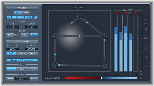
Chapter 8 Metering tools 15 6
Surround MultiMeter Balance/Correlation
The Surround MultiMeter’s Correlation Meter gauges the balance or sound placement between
all incoming signals. Strongly correlated signals are shown as sharp markers and less strongly
correlated signals as a blurred area.
Click the Balance/Correlation button to view the Correlation Meter in the main display.
Depending on the chosen surround format, a number of points that indicate speaker positions
are shown (L, R, C, Ls, Rs in a 5.1 conguration are displayed in the gure). Lines connect these
points. The center position of each connecting line is indicated by a blue marker.
A gray ball indicates the surround eld/sound placement. As you move the surround panner of
the channel strip, the ball in the Correlation Meter mirrors your movements. The blue markers
also move in real time, with shaded gray lines indicating the divergence from the centered
positions on each of the connecting lines.
The LFE channel Correlation Meter is shown at the bottom of the main display. The horizontal
area around the white correlation indicator denotes phase correlation deviations in real time.
This is shown in both directions. A vertical red line to the left of the correlation indicator shows
the maximum negative phase deviation value. You can reset this line by clicking it during
playback.
The LFE Correlation Meter’s scale values indicate the following:
•A +1 correlation value indicates that the signal is balanced.
•Correlation values in the blue zone (between +1 and the middle position) indicate that the
signal is mono compatible.
•The middle position indicates the highest allowable amount of channel divergence.
•When the meter moves into the red area to the left of the center position, out-of-balance
material is present.
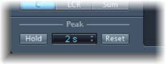
Chapter 8 Metering tools 157
Surround MultiMeter Peak parameters
The Surround MultiMeter oers the following Peak parameters:
Surround MultiMeter Peak parameters
•Hold button: Click to turn on peak hold for all metering tools in Surround MultiMeter, as
follows:
•Analyzer: A small yellow segment above each level bar indicates the most recent peak level.
•Goniometer: All illuminated pixels are held during a peak hold.
•Level Meter: A small yellow segment above each level bar indicates the most recent peak
level.
•Balance/Correlation Meter: The horizontal area around the white correlation indicator denotes
phase correlation deviations in real time, in both directions.
Note: This meter must be manually opened by clicking the Balance/Correlation button.
•Hold Time pop-up menu: Choose the hold time for all metering tools. Choose 2, 4, or 6
seconds—or innite.
Note: The (peak) Hold button must be turned on for the selected time value to have an eect.
•Reset button: Click to reset the peak hold segments of all metering tools.
•Inter Sample Peak Detection checkbox (Extended Parameters area): Select to detect inter-sample
peaks in the signal.
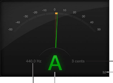
Chapter 8 Metering tools 158
Use the Tuner utility
You can tune instruments connected to your system with the Tuner utility. This ensures that your
external instrument recordings are in tune with any software instruments, samples, or existing
recordings in your projects.
Mute button
Tune Deviation display
Keynote
Drag to set pitch.
Tuner parameters
•Graphic Tuning display: Indicates the pitch of the note in cents. At the centered (12 o’clock)
position, the note is correctly tuned. If the indicator moves to the left of center, the note is at.
If the indicator moves to the right of center, the note is sharp. Color is also used to indicate
tuning accuracy, with green denoting a tuned signal, and orange indicating a detuned signal.
•Reference Tuning eld: Drag vertically to set the pitch of the note used as the basis for tuning.
The default is for note A at 440 Hz and can be set in a range from 410 to 470 in 0.1 Hz steps.
•Keynote display: Shows the target pitch of the note being played (the closest tuned pitch).
•Tune Deviation display: Shows the tuning deviation in cents.
•Mute button: Click to mute the active channel.
Use the Tuner
1 Insert the Tuner plug-in into an audio channel strip.
2 Play a single note on the instrument and watch the Graphic Tuning and Keynote displays. If the
note is at or sharp of the keynote, orange segments are shown in the Graphic Tuning display,
the Keynote is shown in orange, and the Tune Deviation display indicates how far (in cents) the
note is o pitch.
3 Adjust the tuning of your instrument until the indicator is centered in the Graphic Tuning display
and the Tune Deviation eld shows zero (0 cents).
The Graphic Tuning display and Keynote are shown in green when correctly tuned.
15 9
Use MIDI plug-ins
MIDI plug-ins are inserted in software instrument channel strips and process or generate MIDI
data—played from a MIDI region or a MIDI keyboard—in real time.
MIDI plug-ins are connected in series before the audio path of a software instrument channel
strip.
MIDI plug-ins have a MIDI input, the MIDI processor, and a MIDI output. The output signals sent
from MIDI plug-ins are standard MIDI events such as MIDI note or controller messages.
Insert one or more MIDI plug-ins
1 Click the space between the EQ graphic and the Instrument slot of a software instrument
channel strip.
2 Choose the name of the MIDI plug-in you want to use from the MIDI plug-ins pop-up menu.
The selected MIDI plug-in window opens, and a green label with the MIDI plug-in name is shown
in the channel strip.
3 To insert additional MIDI plug-ins, move the pointer over the top or bottom edge of the inserted
MIDI plug-in label in the channel strip, then click when you see a green line.
Note: The plug-in window does not open automatically for MIDI plug-ins inserted in this way.
Click the label to open the plug-in window.
Change the order of MIDI plug-ins
mDrag the label of the MIDI plug-in that you want to move over the label of the target MIDI
plug-in.
•If the target MIDI plug-in is in the top slot: It is moved down the list.
•If the target MIDI plug-in is in the bottom slot: It is moved up the list.
•If the target MIDI plug-in is in a middle slot: The positions of the two plug-ins are swapped.
Remove a MIDI plug-in
mClick the arrows near the right edge of the MIDI plug-in label that you want to remove, then
choose No Plug-in from the pop-up menu.
Bypass a MIDI plug-in
1 Click the Bypass button near the left edge of the MIDI plug-in label.
The plug-in label is dimmed. All parameter settings of the plug-in are retained when bypassed.
2 Click the Bypass button to restore the MIDI plug-in.
MIDI plug-ins 9
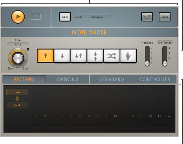
Chapter 9 MIDI plug-ins 160
Arpeggiator MIDI plug-in
Arpeggiator overview
The Arpeggiator MIDI plug-in generates musically interesting arpeggios based on incoming
MIDI notes. It provides split and remote features that allow you to control nearly all
Arpeggiator functions without taking your hands o the keyboard, making it a powerful live
performance tool.
An arpeggio is a succession of notes in a chord. Rather than all notes being played at one time,
they are played one after the other in a pattern: up, down, random, and so on. The Arpeggiator
plug-in provides a number of preset patterns, inclusive of switchable variations and inversions.
Inversions change the root note of the chord from the lowest note, resulting in a dierent start
note in arpeggiated patterns. These features let you quickly switch between patterns and feels
when performing live, or when creating new projects in the studio.
Control parameters Note order parameters
Click here to access
Advanced parameters.
The Arpeggiator MIDI plug-in is divided into three areas.
•Control parameters: This area contains the Play and Latch controls. See Arpeggiator
control parameters.
•Note order parameters: The note order parameters determine the arpeggio type and include
four variations or inversions, the arpeggio octave range, and the arpeggio speed. See
Arpeggiator note order parameters overview.
•Advanced parameters: The advanced Arpeggiator controls are divided into four tabs. Click the
Pattern, Options, Keyboard, or Controller tab to open each parameter group. See Arpeggiator
pattern parameters overview, Arpeggiator options parameters, Arpeggiator keyboard
parameters, and Assign Arpeggiator controller parameters.
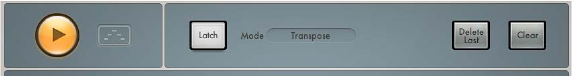
Chapter 9 MIDI plug-ins 161
Arpeggiator control parameters
The control parameters start and stop the Arpeggiator and determine the latching behavior. You
can also capture a live arpeggio as a MIDI region.
Control parameters
•Play button: Click to start or stop arpeggiated playback of note input from a MIDI keyboard
or a MIDI region. The Play button is lit when in play mode. When the Arpeggiator plug-in is
stopped, incoming MIDI notes are passed through, and the settings of the split and remote
keyboard parameters are retained. See Arpeggiator keyboard parameters.
•When Logic Pro is in play mode: The arpeggio starts playing whenever the Arpeggiator Play
button is on, including when the plug-in is rst inserted. Arpeggio playback is linked to the
Logic song position.
•When Logic Pro is stopped: Arpeggio playback stops. Incoming MIDI notes are passed
through, and keyboard split and remote settings are retained.
Note: You can click the Arpeggiator Play button while Logic Pro is stopped to begin arpeggio
playback from the rst step in the arpeggio.
•Capture live performance button: Click the button, then drag the playing arpeggio to any
software instrument track. The currently playing arpeggio pattern is placed as a MIDI region at
the target position.
•Latch button: Click to turn Latch mode on or o. This enables an arpeggio to run without the
need for you to hold down keys. Latch mode behavior is determined with the Latch mode
pop-up menu.
•Latch mode pop-up menu: Choose a Latch mode:
•Reset: The rst key played clears the currently latched notes.
•Transpose: Play a single key to transpose the arpeggio relative to the note value of the
pressed key and the lowest arpeggiated note.
Note: Pressing more than one key simultaneously clears currently latched notes and starts a
new arpeggio.
•Gated Transpose: This option is the same as Transpose Latch mode with the dierence that
the arpeggio only plays while a key is pressed. As soon as the key is released, the arpeggio
is muted.
•Add: Play keys—one by one, or simultaneously as a chord—to add them to the latched
arpeggio. You can play the same key multiple times and the note repeats the number of
times it is struck.
•Add Temporarily: This option is the same as Add Latch mode except that played notes are
added to the latched arpeggio only while held. When a temporarily added key is released, it
is removed from the arpeggio.
•Through: All incoming MIDI notes are passed through the Arpeggiator plug-in, enabling you
to play along with a latched arpeggio.
•Delete Last button: Click to delete the last event—a note, rest, or tie—that was added to
the arpeggio.
Note: Each event is allocated a unique position identication number and the “last” event has
the highest position identication number.
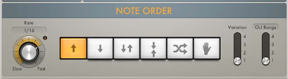
Chapter 9 MIDI plug-ins 162
•Clear button: Click to remove all notes from the Arpeggiator plug-in latch memory. The
arpeggio stops playing and all position identication numbers are reset to zero, enabling
you to create a new arpeggio without turning o Latch mode, which can be useful in a live
situation when preparing for a chord change.
•Silent Capture checkbox (extended parameter): Click the disclosure triangle at the lower left to
display the extended parameters. Select the Silent Capture checkbox to capture an arpeggio
step by step without being disturbed by the immediate response of the running arpeggiator.
•When enabled, the arpeggiator is stopped and Latch/Add mode is engaged.
•When disabled, Play is re-engaged (if previously active) and Latch mode switches
to Transpose.
Arpeggiator note order parameters
Arpeggiator note order parameters overview
The note order parameters provide control of a pre-programmed order of notes that are played
at a preset playback rate. Once all notes are played, the arpeggio cycles from the start. When
you play a single key, it is repeated. When you play multiple keys, the held notes are played one
after the other. As you play additional notes, these are seamlessly added to the arpeggio. When
you release notes, they are removed from the arpeggio. The arpeggio stops when you release all
played keys (unless Latch mode is turned on in the Arpeggiator control parameters).
The Arpeggiator plug-in automatically assigns position identication numbers to each note in
the order they are played. These position identication numbers associate an event, such as a
note, rest, or a tie, with a particular step. This lets you switch between note order presets while
retaining a rest on the third step, for example.
Note order parameters
All note order parameters can be changed while an arpeggio is playing. Changes are immediate
and are seamlessly applied to the running arpeggio.
•Rate knob and eld: Rotate to set the arpeggiator rate. Choose from: 1/4, 1/8, 1/16 (including
triplet and dotted notes), and 1/32. You can also click the eld to choose a value from a
pop-up menu. The LED indicates the rate and briey changes color at the start of each
new cycle.
•Direction buttons: Click a button to set the arpeggio direction.
•Up: The arpeggio is played from the lowest note to the highest note.
•Down: The arpeggio is played from the highest note to the lowest note.
•Up/Down: The arpeggio plays up and down, from the lowest note; the highest and lowest
notes repeat.
•Outside-in: The arpeggio plays the highest then the lowest notes, then the second highest
and second lowest, the third highest and third lowest, and so on.
•Random: Arpeggiated notes play in a random order.
•As played: All notes play in the order they were triggered.
Chapter 9 MIDI plug-ins 163
•Lock button: Works in conjunction with the As played button. When you rst click the As
played button, an open lock symbol is shown. Click the open lock symbol once you have
triggered an arpeggio to lock the current note order, indicated by a closed lock. This note
order and feel is retained for any newly triggered arpeggios, but with new notes replacing
the original notes. Click the lock symbol again to clear the locked note order and to revert to
the standard “as played” behavior. The lock state and note order can be saved with a setting.
•Variation switch: Move to one of the four positions to determine the type of variation. See
Arpeggiator note order variations for details.
•Oct Range/Inversions button: Click to switch between two modes: Octave Range or Inversions.
The four-position Oct Range/Inversion switch below the buttons is used to determine the
octave range or the chord inversion pattern.
•Oct Range/Inversion switch: Move to one of the four positions to determine the octave range
or the chord inversion pattern. See Arpeggiator note order inversions for details on the four
switch position behaviors in Inversions mode.
In Octave Range mode:
•Position 1: The arpeggio repeats without transposition.
•Position 2: The lowest note is transposed by one octave. Once repeated, the arpeggio restarts
in the original octave.
•Position 3: The rst repetition is transposed by one octave, and the second repetition is
transposed by two octaves. Once the second repetition is played, the arpeggio restarts in the
original octave.
•Position 4: The rst repetition is transposed by one octave, the second by two octaves, and
the third by three octaves. Once the third repetition is played, the arpeggio restarts in the
original octave.
In Inversions mode:
•Position 1: The arpeggio repeats without inverting the held notes.
•Position 2: The arpeggio is inverted once during the rst repetition. Once repeated, the
arpeggio restarts.
•Position 3: The arpeggio is inverted twice, once each during the rst and the second
repetition. Once the second repetition is played, the arpeggio restarts.
•Position 4: The arpeggio is inverted three times, once each during the rst, second, and third
repetitions. Once the third repetition is played, the arpeggio restarts.

Chapter 9 MIDI plug-ins 164
Arpeggiator note order variations
The table outlines the Arpeggiator behavior in each note order preset when the Variation switch
is set to the four available positions.
Note order Variation 1 Variation 2 Variation 3 Variation 4
Up Plays from the
lowest to highest
note in consecutive
order and restarts
when all keys are
played.
Plays the second
step rst. This
variation consists
of four steps; all
pressed keys are
divided into groups
of four with the
note order applied
to all groups. If
there are fewer
than four notes, the
steps without an
assigned key are
skipped. Once all
keys are played, the
arpeggio restarts
with the lowest
note.
Plays the third step
rst. This variation
consists of four
steps; all pressed
keys are divided
into groups of
four with the note
order applied to
all groups. If there
are fewer than
four notes, the
steps without an
assigned key are
skipped. Once all
keys are played, the
arpeggio restarts
with the lowest
note.
This variation,
which consists of
three steps, plays
up and overlaps;
all pressed keys are
divided into groups
of three with the
note order applied
to all groups. If
there are fewer
than three notes,
the steps without
an assigned key are
skipped. Once all
keys are played, the
arpeggio restarts
with the lowest
note.
Down Plays from the
highest to lowest
note in consecutive
order and restarts
when all keys are
played.
Plays the second
step rst. This
variation consists
of four steps; all
pressed keys are
divided into groups
of four with the
note order applied
to all groups. If
there are fewer
than four notes, the
steps without an
assigned key are
skipped. Once all
keys are played, the
arpeggio restarts
with the highest
note.
Plays the third step
rst. This variation
consists of four
steps; all pressed
keys are divided
into groups of
four with the note
order applied to
all groups. If there
are fewer than
four notes, the
steps without an
assigned key are
skipped. Once all
keys are played, the
arpeggio restarts
with the highest
note.
This variation,
which consists of
three steps, plays
down and overlaps;
all pressed keys are
divided into groups
of three with the
note order applied
to all groups. If
there are fewer
than three notes,
the steps without
an assigned key are
skipped. Once all
keys are played, the
arpeggio restarts
with the highest
note.
Up and down Plays from the
lowest to highest
note in consecutive
order, then plays
from the highest
to the lowest note,
and restarts when
all keys are played.
Plays from the
lowest to highest
note in consecutive
order, then plays
from the second
highest to the
second lowest note,
and restarts when
all keys are played.
This two-step
variation works
with pairs of notes.
The second note
of the pair plays
rst. In a four-note
chord, the order is
2, 1, 4, 3. Once the
pattern is played,
the note order is
reversed, then the
arpeggio restarts.
This three-step
variation works
with trios of notes.
The note order is
1, 3, 2. Once the
pattern is played,
the note order is
reversed, then the
arpeggio restarts.

Chapter 9 MIDI plug-ins 165
Note order Variation 1 Variation 2 Variation 3 Variation 4
Outside-in Plays the highest
note, then the
lowest note, then
plays the second
highest and the
second lowest note,
and so on. The
arpeggio restarts
when all keys are
played.
Plays the lowest
note, then the
highest note, then
plays the second
lowest and the
second highest
note, and so on.
The arpeggio
restarts when all
keys are played.
This is an inside-
out variation. The
number of played
keys is divided
by two (rounded
up to the nearest
whole number).
The highest center
note is played, then
the low-center
note, and so on. In
a six-note chord,
the order is 4, 3, 5,
2, 6, 1. The arpeggio
restarts when all
keys are played.
This is an inside-
out variation. The
number of played
keys is divided
by two (rounded
up to the nearest
whole number).
The lowest center
note is played, then
the high-center
note, and so on. In
a six-note chord,
the order is 3, 4, 2,
5, 1, 6. The arpeggio
restarts when all
keys are played.
Random Played note
order is randomly
generated and can
include duplicate
notes.
Played note
order is randomly
generated but
no note is played
twice. The arpeggio
restarts when all
keys are played.
This variation
favors low notes.
Played note
order is randomly
generated and can
include duplicate
notes.
This variation
favors high notes.
Played note
order is randomly
generated and can
include duplicate
notes.
As played Plays all notes in
the order they
were played, then
restarts.
Plays all notes in
the reverse order
they were played,
then restarts.
Plays all notes in
the order they were
played, then plays
notes in reverse
order, doubling the
rst and last played
notes. The arpeggio
restarts once all
notes are played.
Plays all notes in
the order they were
played, then plays
notes in reverse
order, but does
not repeat the rst
and last played
notes. The arpeggio
restarts once all
notes are played.

Chapter 9 MIDI plug-ins 166
Arpeggiator note order inversions
The table outlines the Arpeggiator behavior in each note order preset when the Oct Range/
Inversion switch is set to the four positions in Inversions mode (set with the Oct Range/
Inversions button). Inversions change the root note of the chord, resulting in a dierent start
note to arpeggiated patterns.
Note order Inversion 1 Inversion 2 Inversion 3 Inversion 4
Up Plays the original
chord, then
three inversions
in consecutive
order and restarts.
Playback order:
original, 1, 2, 3.
Plays the second
inversion rst.
Playback order: 1,
original, 2, 3.
Plays the third
inversion rst.
Playback order: 2,
original, 1, 3.
This variation,
which consists of
three steps, plays
up, and overlaps.
Playback order:
original, 2, 1, 3.
Down Plays the original
chord, then
three inversions
in consecutive
order and restarts.
Playback order: 3, 2,
1, original.
Plays the second
step rst. Playback
order: 2, 3, 1,
original.
Plays the third step
rst. Playback order:
1, 3, 2, original.
This variation,
which consists of
three steps, plays
down, and overlaps.
Playback order: 3, 1,
2, original.
Up and down Plays the original
chord, then three
inversions in
consecutive order,
then reverses the
order, repeating
the rst and last.
Playback order:
original, 1, 2, 3, 3, 2,
1, original.
Plays the second
step rst. Playback
order: 1, original, 3,
2, 2, 3, original, 1.
Once the pattern is
played, the order is
reversed, then the
arpeggio restarts.
Playback order:
original, 2, 1, 3, 3, 1,
2, original.
Once the pattern
is played, the order
is reversed, but
the third inversion
is not repeated.
Playback order:
original, 1, 2, 3, 2, 1.
Outside-in Plays the highest
inversion, then the
original, then plays
the second highest
and the second
lowest inversion,
and so on. Playback
order: 3, original,
2, 1.
Plays the original,
then the highest
inversion, then
plays the second
lowest and the
second highest
inversion, and so
on. Playback order:
original, 3, 1, 2.
This is an inside-out
variation. Playback
order: 1, 2, original,
3.
This is an inside-out
variation. Playback
order: 2, 1, 3,
original.
Random Played inversion
order is randomly
generated and can
include duplicate
chord inversions.
Played inversion
order is randomly
generated but no
chord inversion is
played twice.
This variation
favors low chord
inversions. Played
inversion order
is randomly
generated and can
include duplicate
chord inversions.
This variation
favors high chord
inversions. Played
inversion order
is randomly
generated and can
include duplicate
chord inversions.
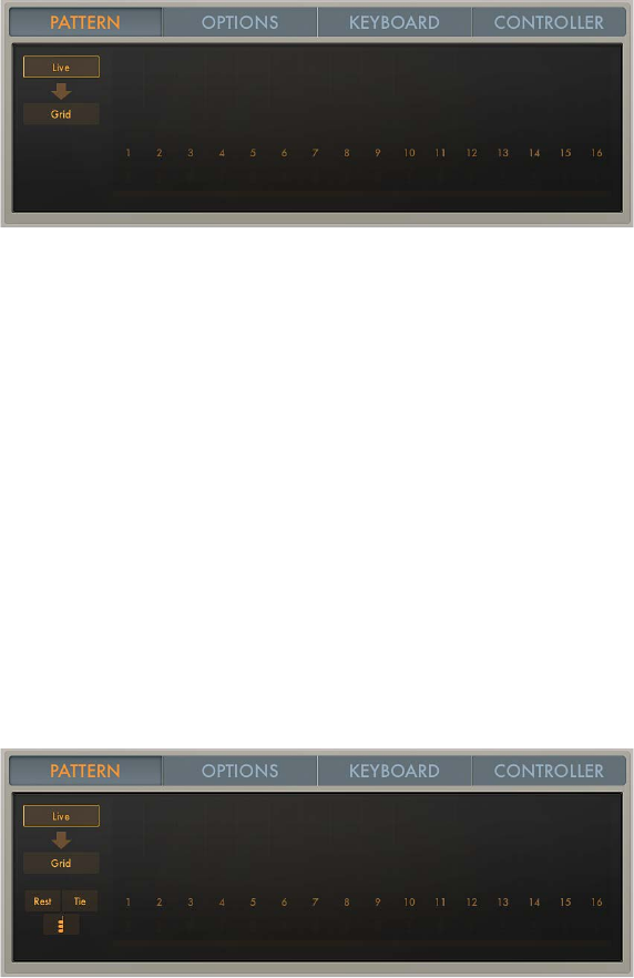
Chapter 9 MIDI plug-ins 167
Arpeggiator pattern parameters
Arpeggiator pattern parameters overview
Click the Pattern tab to open the Arpeggiator pattern parameters.
The Pattern tab includes two distinct functional modes: Live and Grid. The modes are mutually
exclusive, so turning on one turns o the other. It also provides a unique Live Capture to
Grid facility.
When Grid mode is active, it controls the arpeggio’s velocity, cycle length, rests, ties, and chords.
All live input of available grid parameters, such as velocities, is ignored.
When you switch to Live mode, the arpeggio performance is controlled live by your input. For
example, the velocities of arpeggiated notes are determined by the way you played them. Any
existing grid values are retained but are disabled until you return to Grid mode.
Note: When you capture a live performance, grid values are not retained.
Pattern parameters
•Live button: Click to turn on Live mode. See Arpeggiator Live mode.
•Arrow button (Live mode only): Click to capture the currently playing velocities, rests, ties, and
chords. Grid mode is automatically turned on and the captured performance can be edited in
the grid. See Arpeggiator Grid mode.
•Grid button: Click to turn on Grid mode.
Arpeggiator Live mode
In Live mode, you can add rests, ties, and chords in real time by clicking the onscreen buttons or
by using equivalent MIDI keyboard remote keys. See Arpeggiator keyboard parameters.
The grid acts as a display only. Incoming MIDI velocities, rests, ties, and chords are displayed in
real time but cannot be edited in the grid. To edit individual arpeggiator steps, click the Grid
button to turn on Arpeggiator Grid mode.
Note: Rests, ties, and chords are active only when Latch mode is turned on. See Arpeggiator
control parameters.
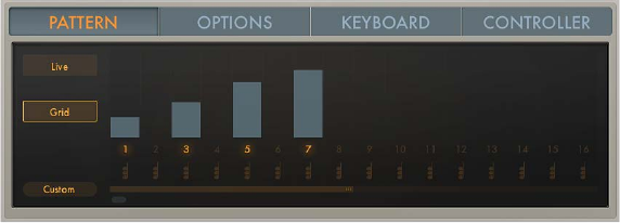
Chapter 9 MIDI plug-ins 168
Live mode parameters
•Rest button: Click to insert a rest at the current arpeggiator step position. A position
identication number is assigned to the rest, ensuring that its rhythmic position (step number)
within the arpeggio is retained, even when dierent note order presets are chosen.
Note: Rests can only be added while building the arpeggio, which means that at least one
key must be held if you want to add a rest. Once all keys are released, the Arpeggiator acts
in accordance with the rules of the set Latch mode and expects to receive a MIDI note for
transposition and so on. In Latch Add mode, this restriction does not apply because it allows
you to add MIDI notes, rests, ties, and chords after all keys are released.
•Tie button: Click to insert a tie at the current arpeggiator step position. A position identication
number is assigned to the tie, ensuring that its rhythmic position (step number) within the
arpeggio is retained, even when dierent note order presets are chosen.
•Chord button: Click to insert a chord at the current arpeggiator step position. When the
arpeggiator encounters a chord step, it simultaneously plays all notes, including their unique
velocities, currently in memory (latched or held). A position identication number is assigned
to the chord, ensuring that its rhythmic position (step number) within the arpeggio is retained,
even when dierent note order presets are chosen.
Arpeggiator Grid mode
The grid consists of 16 steps. Each step controls the step velocity as well as its rest, tie, and chord
status. In addition, a cycle length can be set. The current grid pattern is automatically saved with
the Logic project. You can also save and load your own or factory grid patterns. The Arpeggiator
plug-in assigns incremental position identication numbers to each note in the order they
were received, regardless of the initially selected note order preset. These position identication
numbers are used to “lock” an event, such as a note, a rest, or a tie to a particular step.
Grid mode parameters
•Step on/o buttons: Click to turn each of the 16 available steps on or o.
•If a step is turned on: An arpeggiator note is played at the respective grid position.
•If a step is turned o: The grid position is silent and is perceived as a rest.
Note: To ensure the integrity of the arpeggio, the note that would have been played—if the
step had been active—is moved to the next active grid position.
•Velocity bars: Drag the velocity bar vertically to set the velocity for each active step. Where
multiple velocity bars exist, click above them to draw in the velocity of several steps.
Drag the velocity bar toward the right to overlap the next step, thus tying it to that step. If the
step to the right is a rest (an inactive step) this step is automatically turned on to create the
tie. A step can be tied to multiple steps in a row. The original velocity values of tied steps are
replaced by the velocity of the rst step they are tied to, indicated graphically by the velocity
bar extending over all tied steps.
Chapter 9 MIDI plug-ins 169
Note: Within an arpeggio, ties are perceived as a rhythmic element rather than a melodic
variation. As a consequence, the tied note may change if notes are added after the tie has
been entered or when you choose a dierent note order preset.
•Chord on/o buttons: Click the chord symbol to turn on Chord mode for the respective step.
When the Arpeggiator encounters a chord step, it simultaneously plays all notes currently in
(latched or held) memory on that step. If a chord step is tied to a non-chord step, Chord mode
is automatically activated for that step. If a non-chord step is tied to a chord step, Chord mode
is automatically turned o for that step. Moving the velocity bar on a chord step changes
the overall level of the chord, while retaining relative velocity dierences between notes in
the chord.
•Cycle length bar: Drag the cycle handle at the end of the cycle length bar to change the grid
length. The currently playing step is indicated by a light running inside the Cycle length bar.
Note: The grid length set with the Cycle length bar is independent of the Arpeggio cycle
length parameter (which sets the length of the arpeggiated note pattern) described in
Arpeggiator options parameters. The grid length cycles independently of the eective note
pattern, ensuring that the perceived rhythmic pattern created by the grid is not disrupted by a
changing arpeggio length.
•Pattern pop-up menu: Choose one of the following items to save or load user grid patterns or
to load a factory grid pattern.
•Save Pattern as: Opens a name eld. Enter a name, then click the Save button to save your
pattern. Click Cancel to exit the “Save Pattern as” name eld.
User patterns are shown in the Pattern pop-up menu.
Note: Factory grid patterns cannot be overwritten. If you attempt to do so, a Save Pattern as
name eld appears.
•Recall Default: Deletes all current data and reverts to a “from scratch” state.
•Delete User Pattern: Deletes the current user pattern.
•Custom: This menu item is shown automatically when any pattern changes have been made.
It can be considered the “current state” pattern preset.
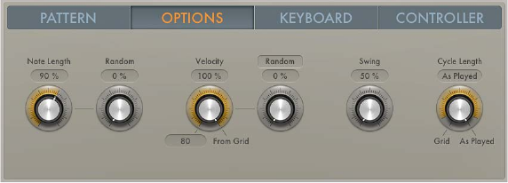
Chapter 9 MIDI plug-ins 17 0
Arpeggiator options parameters
Click the Options tab to set global Arpeggiator playback parameters, such as note length
and velocity.
Options parameters
•Note Length knob: Rotate to dene the length of the arpeggiated notes. This ranges from 1 to
150%.
•Random knob: Rotate to set the amount of random note length variation.
•Velocity knob: Rotate to determine the maximum range of possible velocity values for
arpeggiated notes. At the far right position (100%), the original velocities of recorded or played
notes are retained. At the far left position (0%), the original velocities of recorded or played
notes are ignored and all notes are output at a constant velocity.
•Vel (Velocity Base) eld: Drag vertically to set a minimum velocity value that is used for random
velocity modulations and crescendos.
•Crescendo/Random button: Click to switch between two modes: Random and Crescendo.
The amount of variation is controlled with the Crescendo/Random knob. The range of the
crescendo or possible random velocities is set with the Velocity parameters.
•Crescendo/Random knob: Rotate to set the strength of the crescendo when the Crescendo/
Random button is set to Crescendo. Rotate to set the amount of random velocity variation
when the Crescendo/Random button is set to Random.
•When set to Crescendo: The set amount is added to, or subtracted from, the velocity of all
notes on each arpeggio repetition, starting with the second cycle.
•When set to Random: The velocity values of all notes are randomized symmetrically by the set
amount. At a value of 0% there is no randomization applied. At a value of 100% the velocity
values are completely randomized.
•Swing knob and eld: Rotate to set the strength of note swing. The Swing parameter moves
every second note in the arpeggio closer to the nearest downbeat. A value of 0% results in no
note movement, whereas a value of 100% results in extreme note movement.
•Cycle Length knob: Rotate to set a length for the arpeggio. You can choose from the following:
•By Grid: Matches the arpeggio length to the global Logic Pro division setting. This is useful
for rhythmically synchronizing the arpeggio length with other regions.
•1 to 32: Set the arpeggio length to the specied number of notes.
•As played: The arpeggio length is determined by the length of played notes.
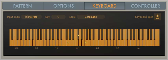
Chapter 9 MIDI plug-ins 171
Arpeggiator keyboard parameters
Click the Keyboard tab to open the Arpeggiator keyboard parameters. The dots shown on
the keyboard represent the output of currently playing notes, including any key and scale
adjustments. You can also open the Remote Key editor window from the Keyboard tab. For
further details, see Use Arpeggiator keyboard parameters.
Keyboard parameters
•Input Snap pop-up menu: Choose a beat value that is used to “snap” the rst incoming note to a
position, thus quantizing the start (and playback) of the arpeggio.
The default Input snap pop-up menu value is “link to rate,” which matches the set Arpeggiator
Rate (see Arpeggiator note order parameters overview).
•Key pop-up menu: Choose a root key for the chosen scale. C is the default key.
•Scale pop-up menu: Choose a scale. Played keys are snapped to the nearest note in the chosen
scale. Choose from: O/Chromatic (default), Major, Major Pentatonic, Major Blues, Lydian,
Mixolydian, Klezmer, Minor Pentatonic, Minor Blues, Japanese, Minor, Harmonic Minor, Dorian,
Phrygian, Lochrian, and South-East Asian.
•Keyboard Split button: Click to divide your MIDI keyboard range into three zones.
•Remote (Key editor) button: You must rst click the Keyboard Split button to make the Remote
(Key editor) button visible. The Remote button opens the Remote Key editor window where
you can assign a range of MIDI keys to Arpeggiator functions.
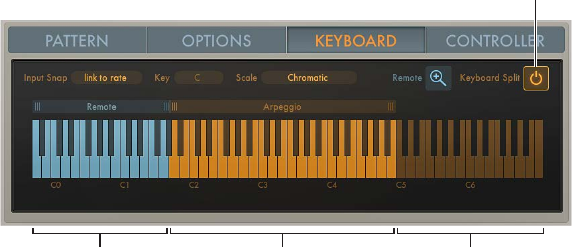
Chapter 9 MIDI plug-ins 17 2
Use Arpeggiator keyboard parameters
The Arpeggiator keyboard parameters let you split your keyboard into zones that are used
for standard note playback, arpeggio note triggering, and remote control of the Arpeggiator
plug-in parameters.
Resize the keyboard display
The default keyboard range spans the 88 notes from C0 to C7.
mClick the keyboard, then drag left or right to reveal additional octaves, in one octave increments.
Set up a keyboard split
By default, the complete MIDI key range (0–127) is used solely for arpeggiating. You can split your
MIDI keyboard into several zones to control Arpeggiator plug-in functions with MIDI keys. The
onscreen keyboard reects the split layout.
Keyboard Split button
Remote Arpeggio Through
mTo divide your MIDI keyboard range into three zones, click the Keyboard Split button.
•Arpeggio: Notes played in this keyboard zone are arpeggiated.
•Remote: Notes played in this zone trigger an Arpeggiator function.
•Through: Notes are passed through the Arpeggiator plug-in unprocessed.This zone covers all
keys outside the two zones listed above.
Resize the Arpeggio or Remote zone
mDrag the handles above each end of the Arpeggio or Remote zone to resize it.
Move the Arpeggio or Remote zone
mClick the name of either the Arpeggio or Remote zone and drag to the left or right. If the zones
are adjacent, both zones are moved.
The Arpeggio and Remote zones can swap places so that the Remote zone sits above the
Arpeggio zone or vice versa, but the two zones cannot overlap.
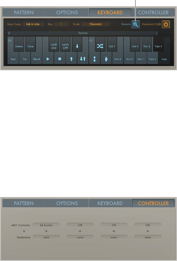
Chapter 9 MIDI plug-ins 173
Remote control the Arpeggiator with a MIDI keyboard
Most Arpeggiator parameters can be remote controlled using a MIDI keyboard. By default,
only a few Remote commands are available. You can resize the Remote zone to make more
commands available.
Remote button
1 You must rst click the Keyboard Split button to display the Remote (Key editor) button.
The type and number of available remote keys is determined by the Remote zone range. Keys
outside this range are dimmed and assigned functions cannot be remote controlled with a MIDI
keyboard.
2 Click the Remote button to open the Remote Key editor window.
A zoomed-in keyboard is displayed, with each key labeled according to its assigned function.
Click the Remote button a second time to close the Remote Key editor window. You can also
click the Keyboard Split button to exit the Remote Key editor window.
3 Drag the left or right border of the range bar above the Remote Key editor keyboard to resize
the Remote zone.
Assign Arpeggiator controller parameters
Click the Controller tab to assign up to four MIDI controllers to Arpeggiator plug-in parameters.
Assign a MIDI controller to an Arpeggiator parameter
1 Choose a MIDI controller from any of the MIDI Controller pop-up menus.
2 Choose a parameter from any of the Destination pop-up menus. Choices are: Note Length, Note
Length Random, Velocity Range, Velocity Base, and (De-)Crescendo.
Learn a MIDI controller
1 Choose a parameter from any of the Destination pop-up menus.
2 Choose Learn from any of the MIDI Controller pop-up menus.
3 Move a controller on your MIDI keyboard to assign it to the Destination parameter.
The Learn feature has a 20-second time out facility. If you do not move a controller on your MIDI
device within 20 seconds, Learn mode is automatically disabled.
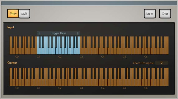
Chapter 9 MIDI plug-ins 174
Chord Trigger MIDI plug-in
Chord Trigger overview
The Chord Trigger MIDI plug-in lets you trigger chords by playing a single MIDI key. The onscreen
keyboards have two functions: the display of incoming and outgoing MIDI notes and the
assignment of chords to keys. See Use Chord Trigger.
Chord Trigger parameters
•Single and Multi buttons: Click either the Single or Multi button to select a mode.
•Single Chord mode: This mode lets you assign a single chord to a trigger key. When playing
up and down the keyboard, the memorized chord is transposed in relation to the trigger key.
This mimics the Chord Memo or Note Stack feature found on many classic synthesizers.
•Multi Chord mode: This mode lets you assign a dierent chord to each key on the keyboard.
•Upper keyboard: Shows incoming MIDI notes, represented by orange dots and the blue shaded
chord trigger range. Drag the handles above the keyboard to set the chord trigger range.
Notes that fall within this range are processed. Notes outside the range are not processed. You
can also click notes in the chord trigger range to trigger chords.
•Lower keyboard: Shows the resulting MIDI output—the chords triggered by incoming MIDI
notes. The notes of each chord (in the chord trigger range) are displayed as blue dots. Chords
outside the chord trigger range are displayed as orange dots.
•Learn button: Click to turn on Learn mode. See Use Chord Trigger for details on using
Learn mode.
•Clear button: Click to erase a Trigger Key note and the corresponding chord. See Use Chord
Trigger for details.
•Chord Octave pop-up menu: Choose an octave transposition value for chord playback.
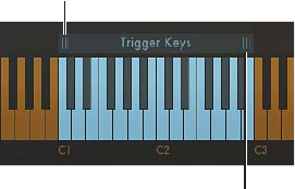
Chapter 9 MIDI plug-ins 175
Use Chord Trigger
Chord Trigger is straightforward to use: choose a mode, set a chord trigger range, select a trigger
key, then set up a chord. You can also transpose chords and quickly assign multiple chords—
onscreen or with your MIDI keyboard.
Dene the chord trigger range
The shaded chord trigger range is shown on the upper keyboard. Incoming MIDI notes that fall
within this range are interpreted as trigger keys that play the chord (Single Chord mode) or the
chords (Multi Chord mode) assigned to them. Chords can be assigned to keys within the chord
trigger range. Incoming MIDI notes that fall outside the dened chord trigger range are passed
through Chord Trigger unaected. This allows you to play a melody with the right hand while
triggering/transposing memorized chords with the left, for example.
Drag here to define a
keyboard range.
Drag here to define a
keyboard range.
mDrag the handles of the chord trigger range bar above the upper keyboard to dene a
keyboard range.
•In Single Chord mode: Playing a MIDI note (or clicking the upper keyboard) within the dened
chord trigger range plays and transposes a single memorized chord. The transposition is
performed in relation to the trigger key the chord is assigned to. For example, if a chord is
assigned to C2, playing a D2 transposes the chord upward by two semitones. Playing a B1
transposes the chord down by a semitone.
•In Multi Chord mode: Playing a MIDI note (or clicking the upper keyboard) within the dened
chord trigger range triggers the chord that is memorized for the played key. Keys that do not
have a chord assigned to them are silent when played.
Note: If the chord trigger range is made shorter, memorized chords that fall outside the range
become inaccessible but are not deleted. Lengthening the chord trigger range makes assigned
chords accessible again.
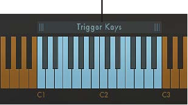
Chapter 9 MIDI plug-ins 17 6
Transpose chords in the chord trigger range (Multi Chord mode only)
You may want to transpose triggered chords in some circumstances. For example, in Multi Chord
mode you can move the entire chord trigger range upward by two semitones to change a chord
progression in C-Major (starting with the C trigger key) into a progression that plays in D-Major,
starting with the D trigger key.
Drag left or right to transpose.
mDrag the center of the chord trigger range left or right.
All memorized chords are moved with the chord trigger range and are automatically transposed.
Transpose chords by octaves
mChoose an octave transposition from the Chord Octave pop-up menu.
All memorized chords can be transposed up or down by up to four octaves.
Assign a chord to a key using the onscreen keyboard
1 Click the Learn button.
The Learn button label changes to “Trigger Key” and the button begins to blink.
2 Click a trigger key—within the chord trigger range—on the upper keyboard.
The trigger key is set up for chord assignment. The Learn (Trigger Key) button label changes to
“Chord.”
3 Click the note or notes you want to assign to the trigger key on the lower keyboard.
As you click each note, you will hear it and any previously assigned notes in the chord.
Click assigned notes a second time to unassign or remove them from the chord.
4 To end chord assignment, click the Learn button.
You can repeat these steps to assign a dierent chord to each key in the chord trigger range
when in Multi Chord mode. In Single Chord mode, only one chord can be learned.
Chapter 9 MIDI plug-ins 17 7
Assign a chord to a key using a MIDI keyboard
It can be faster to use your MIDI keyboard when assigning chords to trigger keys. The Learn
process can be started and stopped by playing an assigned note on your MIDI keyboard.
1 Click the disclosure triangle at the lower left to open the extended parameters.
2 Choose the MIDI note number you want to use as a remote control for the Learn button from
the Learn Remote pop-up menu.
Choose O if you no longer want to use a MIDI note as the Learn button remote control.
3 Play the note selected as the Learn button remote control on your MIDI keyboard.
The Learn button label changes to “Trigger Key” and the button begins to blink.
4 Play a trigger key—within the chord trigger range—on your MIDI keyboard.
This enables the trigger key for chord assignment. The Learn (Trigger Key) button label changes
to “Chord.”
5 Play the note or notes you want to assign to the trigger key on your MIDI keyboard.
As you play each note, you will hear it and any previously assigned notes in the chord.
Play assigned notes a second time to unassign or remove them from the chord.
6 Play the note selected as the Learn button remote control on your MIDI keyboard to end
chord assignment.
You can repeat steps 3–6 to assign a dierent chord to each key in the chord trigger range when
in Multi Chord mode. In Single Chord mode, only one chord can be learned.
Clear a chord assignment
1 Click the Clear button.
•In Single Chord mode: The assigned chord is erased.
•In Multi Chord mode: The button label changes to “Trigger Key” and begins to blink.
2 Click the trigger key that you want to clear on the upper keyboard.
The chord assigned to the trigger key is erased and the trigger key is dimmed, indicating that no
chord is assigned.
Clear all chord assignments
The following applies only to Multi Chord mode.
mPress Option, then click the Clear button.
All chords on all trigger keys are erased.
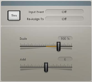
Chapter 9 MIDI plug-ins 17 8
Modier MIDI plug-in
The Modier MIDI plug-in lets you quickly reassign or lter a single continuous controller (CC).
You can also scale or add to event values.
Modier parameters
•Input Thru button: Turn on to dene whether the input event is sent to the output in addition
to the reassignment.
•Input Event pop-up menu: Choose the type of MIDI input event that you want to reassign
or lter.
•Re-Assign To pop-up menu: Choose the type of MIDI output event. If set to O, the event type
chosen from the Input pop-up menu is ltered.
•Scale slider: Drag to set the scaling amount for the output event type chosen from the
Re-assign To pop-up menu.
•Add slider: Drag to set the oset amount for the output event type chosen from the Re-assign
To pop-up menu.
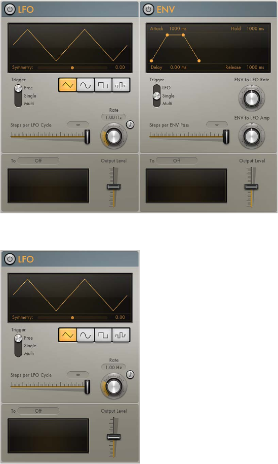
Chapter 9 MIDI plug-ins 17 9
Modulator MIDI plug-in
Modulator MIDI plug-in overview
The Modulator MIDI plug-in can generate continuous controller, aftertouch, and pitch bend
messages. It consists of one syncable LFO and one Delay/Attack/Hold/Release envelope. See
Modulator MIDI plug-in LFO and Modulator MIDI plug-in envelope.
Both the LFO and envelope can be assigned to output any continuous controller, aftertouch, and
pitch bend message. You can also specify a step width for the continuous outputs of the LFO and
envelope, resulting in modulations that are reminiscent of classic Sample & Hold circuits.
Modulator MIDI plug-in LFO
Chapter 9 MIDI plug-ins 18 0
Modulation LFO parameters
•LFO on/o button: Turns the LFO on or o.
•Waveform Shape buttons: Click to select a waveform shape. Choose from: triangle, sine, square,
and random. Each is suited for dierent types of modulations.
•Waveform display: Shows the LFO waveform shape.
•Symmetry slider: Drag to adjust the symmetry of the waveform. This deforms the waveform in
the following ways:
•Triangle: Shapes the triangle waveform into either an upward-sawtooth or downward-
sawtooth waveform. A symmetry value of 0 results in a perfect triangle waveform.
•Sine: Compresses the sine wave into one narrow and one wide duty cycle. A symmetry value
of 0 results in a perfect sine waveform.
•Square: Symmetry acts as a pulse width control. A symmetry value of 0 results in a perfect
square waveform.
•Random: Symmetry determines the maximum deviation between two consecutive
random values. Low symmetry settings result in random values that are minimally dierent
from one to the next, whereas high symmetry settings result in random values that
deviate signicantly.
•Trigger switch: Choose a switch position to determine how the LFO reacts to incoming MIDI
note on messages.
•Free: The LFO ignores MIDI note on messages.
•Single: After all notes have been released, the LFO is reset by the rst MIDI note on message
it receives.
Note: This means that legato playing does not reset the LFO, so keep this in mind
during performances.
•Multi: The LFO is reset by each received MIDI note on message.
•Steps per LFO Cycle (Smoothing) slider and eld: Drag to determine the number of steps per
LFO cycle.
By default, the LFO produces a smoothed continuous stream of controller events, but you
can use this parameter to create a stepped controller signal that is similar to the output of
a Sample and Hold circuit. When you set a manual step rate, the LFO rate can be changed
without altering the number of steps.
Note: If the square or random waveform is selected, the Steps per LFO Cycle slider is
renamed to Smoothing. The slider smooths the normally steep slopes of the square and
random waveforms.
•Rate knob: Rotate to set the cycle speed of the LFO in hertz or in beat values when the Sync
button is turned on. The LFO rate can be modulated by the envelope. See Modulator MIDI
plug-in envelope.
•Sync button: Turn on to synchronize the LFO rate to the Logic Pro song tempo.
•To pop-up menu: Choose a continuous controller number, aftertouch, or pitch bend as the LFO
output target.
•Output Level slider: Move to scale the LFO output level.
•Oscilloscope: The Oscilloscope to the left of the Output Level slider displays the shape of the
LFO control signal before it is scaled.
•MIDI Channel pop-up menu (extended parameter): Click the disclosure triangle at the lower left.
Choose a MIDI output channel.
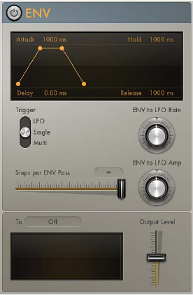
Chapter 9 MIDI plug-ins 181
Modulator MIDI plug-in envelope
Modulation Envelope parameters
•Envelope on/o button: Turns the envelope on or o.
•Envelope display: Shows the current envelope shape. Drag the handles in the display to set the
following parameters:
•Delay: Delays the onset of the envelope. Ranges from 0 to 10 seconds.
•Attack: Sets the time required to reach the sustain level. Ranges from 0 to 10 seconds.
•Hold: Sets the sustain level and duration. Ranges from 0 to 10 seconds.
•Release: Sets the time required for the envelope to fall to a value of zero after the sustain
phase of the envelope has nished. Ranges from 0 to 10 seconds.
•Trigger switch: Choose a switch position to determine if the envelope is triggered by the LFO or
by incoming MIDI note on messages.
•LFO: The envelope is retriggered when the LFO reaches its (positive) peak value. See
Modulator MIDI plug-in LFO.
Note: The envelope ignores incoming LFO triggers if it is currently completing an
envelope pass.
•Single: After all notes have been released, the envelope is re-triggered by the rst MIDI note
on message it receives.
Note: This means that legato playing does not reset the envelope, so keep this in mind
during performances.
•Multi: The envelope is re-triggered by each received MIDI note on message.
•Steps per Env(elope) Pass slider and eld: Drag to determine the number of steps per envelope
pass. By default, the envelope produces a smoothed continuous stream of controller events,
but you can use this parameter to create a stepped controller signal that is similar to the
output of a Sample and Hold circuit. When you set a manual step rate, the envelope time can
be changed without altering the number of steps.
•Env to LFO Rate knob: Rotate to set the maximum amount of LFO modulation (LFO depth). The
LFO rate can be modulated by the Attack, Hold, and Release parameters (see above).
Chapter 9 MIDI plug-ins 18 2
•Env to LFO Amp knob: Rotate to set the maximum amount of LFO output modulation. This
enables you to fade the LFO in or out with the envelope.
•To pop-up menu: Choose a continuous controller number, aftertouch, or pitch bend as the
envelope output target.
•Output Level slider: Move to scale the envelope output level.
•Oscilloscope: The Oscilloscope to the left of the Output Level slider displays the shape of the
envelope control signal before it is scaled.
•MIDI Channel pop-up menu (extended parameter): Click the disclosure triangle at the lower left.
Choose a MIDI output channel.
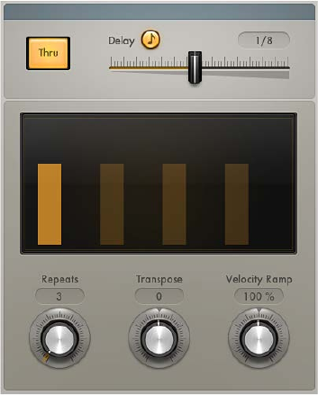
Chapter 9 MIDI plug-ins 18 3
Note Repeater MIDI plug-in
This plug-in mimics an audio delay by generating repeating MIDI notes.
Note Repeater parameters
•Input Thru button: Turn on to pass incoming MIDI note events to the output in addition to the
delayed note events. Turn o to send only the delayed notes to the output.
•Delay Sync button: Turn on to synchronize the plug-in with the host application tempo. Set the
delay time with the Delay slider.
•Delay slider and eld: Drag to set the delay time in milliseconds or in bar/beat values when the
Delay Sync button is turned on.
Note: When the Delay Sync button is turned on, only bar and beat values are available.
•Display: Shows the unprocessed input MIDI note (bright bar) and delayed MIDI notes. The
height of the bars represents the velocity of each delayed MIDI note.
•Repeats knob: Rotate to set the number of delay repetitions.
•Transpose knob: Rotate to transpose each delay repeat by the set amount.
•Velocity Ramp knob: Rotate to scale the velocity level of each delay repeat by the set amount.
•Note Range Min and Max sliders (extended parameter): Click the disclosure triangle at the lower
left to open the extended parameters. Move the Note Range Min and Note Range Max sliders
to set an input note range. Notes that fall within this range are processed (default range:
1–127). Notes outside the range are not processed.
Note: You can position the Note Range Min slider above the Note Range Max slider and vice
versa, which inverts the input note range behavior: note events that fall within the range are
not processed and note events outside the range are processed.
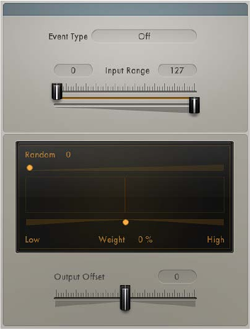
Chapter 9 MIDI plug-ins 18 4
Randomizer MIDI plug-in
The Randomizer plug-in randomizes incoming MIDI events in real time.
Randomizer parameters
•Event Type pop-up menu: Choose the MIDI event type that you want to randomize.
•Input Range sliders: Drag to set the upper and lower limit of the range of values that are
aected. Only parameter values that fall within the range are processed. All values outside the
range pass through the plug-in.
Note: You can position the lower Input Range slider above the upper Input Range slider and
vice versa, which inverts the input range behavior: events that fall within the range are not
processed and events outside the range are randomized.
•Amount slider: Drag to set the intensity of randomization. The colored box shows the range of
possible output values in comparison with the unprocessed input signal shown in the middle.
•Weight slider: Drag to increase or decrease the likelihood that an event will be randomized
within the set Amount range. The colored box reects the weight setting: a darker gradient
means less chance and a brighter color means more chance to produce values in the
respective area.
•Drag toward the left (Low) to increase the chance of low values being randomized.
•Drag toward the right (High) to increase the chance of high values being randomized.
•In the centered position, neither low or high values are favored, resulting in the entire range
of values being randomly altered.
•Output Oset slider: Drag to oset the (random) MIDI output of the plug-in. Osets can be
negative or positive.
•Seed slider (extended parameter): Species a starting point (or seed) for randomization.
An example is when using the Randomizer plug-in to randomize a piano melody. If you
bounce the piano part, your randomized melody is saved as an audio le. If you bounce the
song again, with Seed set to Random, the two bounces sound dierent. If Seed is set to the
same specic value for both bounces, they are identical.

Chapter 9 MIDI plug-ins 18 5
Scripter plug-in
Use the Scripter plug-in
The Scripter plug-in lets you load and use factory or user-created scripts to process or generate
MIDI data in real time. You do not need any programming knowledge to use the plug-ins created
in this environment, but you can view and modify them with the built-in script editor. Once
authored and stored as a setting or patch or as part of a concert or project le, you can use the
plug-in just like any other. A number of pre-built Scripter processors are included.
If you are an advanced user, you can create your own custom MIDI plug-ins. See Use the
Script Editor.
The Scripter plug-in has one global parameter. Further parameters, dened by the JavaScript
script that is currently running, are shown below the global parameter.
•Open Script In Editor button: Click to open the Script Editor window.
You can write your own scripts or can paste scripts from other sources into this window.
Load a pre-built Scripter processor
Do one of the following:
mLoad a setting from the plug-in window header.
mLoad a patch from the Library.
mLoad a channel strip setting from the channel strip Settings pop-up menu or Library.
mLoad a project or concert that contains a Scripter plug-in with a running script.
You do not need to explicitly save an active script as a setting, patch, and so on. Saving the
project or concert retains the script and status of all Scripter plug-ins.
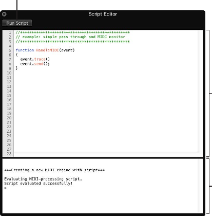
Chapter 9 MIDI plug-ins 18 6
Use the Script Editor
The Script Editor is used to edit JavaScript code, enabling you to write your own MIDI plug-ins.
Plug-in creation is in real time, which means that you can change and test your plug-in functions
immediately. You can dene interface elements, such as sliders and menus, that are shown in
the Scripter plug-in window and can create the underlying logic and functions addressed by
these onscreen controls. Some examples of utilities you can create with the Scripter plug-in are
a chord strummer, a legato processor for stringed instruments, a harp glissando generator, or an
algorithmic composer.
Tip: View the supplied scripts in the Script Editor to see how they are constructed. You can
modify and re-use the code to change functions, or to create new processors.
See the Scripter API overview for Scripter API documentation and code examples.
Run Script button
Code Editor
Interactive Console
Script Editor parameters
•Run Script button: Click to evaluate the script and congure the plug-in and parameters.
Output, including errors, is shown in the Interactive Console when you click this button.
•Code Editor: Type JavaScript code in this area. The editor provides the following features:
•Syntax highlighting for JavaScript keywords and the available MIDI API (Application
Programming Interface).
•Live syntax checking, which highlights error lines immediately, making it easier to write
your scripts.
•Line numbers, which are useful for error checking because they are reported by line number
in the Interactive Console.
•Interactive Console: Displays debugging information and allows you to execute code on the
command prompt by typing after the prompt and pressing Return. Type clear and press
Return to clear the console.
Create and store a Scripter plug-in
1 Open the Scripter plug-in.
2 Click the Open Script In Editor button.
3 Type (or copy and paste existing) JavaScript code in the Code Editor.
Chapter 9 MIDI plug-ins 187
4 Click the Run Script button.
5 Test your plug-in to verify it behaves as intended.
6 Assuming no errors are shown in the Interactive Console, save the host document, setting, or
patch containing the script.
Scripter API overview
You can create your own MIDI processing plug-ins using the JavaScript API described in these
sections.
•MIDI processing functions overview
•JavaScript objects overview
•Create Scripter controls
Tip: View the supplied scripts in the Script Editor to see how they are constructed. You can
modify and re-use the code to change functions or to create new processors. See Use the
Script Editor.
MIDI processing functions
MIDI processing functions overview
The Scripter plug-in exposes a set of JavaScript functions that you can implement in your script
to communicate with the host application. See the linked sections for details about dierent
JavaScript function types and how to use them to create MIDI plug-ins:
•HandleMIDI function
•ProcessMIDI function
•ParameterChanged function
•Reset function
HandleMIDI function
The HandleMIDI() function lets you process MIDI events that the plug-in receives. HandleMIDI
is called each time a MIDI event is received by the plug-in and is required to process incoming
MIDI events. If you do not implement the HandleMIDI function, events pass through the plug-in
unaected.
HandleMIDI is called with one argument, which is a JavaScript object that represents the
incoming MIDI event. HandleMIDI and JavaScript Event object use is shown in the examples.
Code example 1
Pass MIDI events through the plug-in.
function HandleMIDI(event) {
event.send(); }
Code example 2
Log events to the plug-in console and do not send them anywhere.
function HandleMIDI(event) {
event.trace();
}
Chapter 9 MIDI plug-ins 18 8
Code example 3
Repeat notes up one octave with 100ms delay and pass all other events through.
Text following “//” are comments.
function HandleMIDI(event) {
event.send(); // send original event
if (event instanceof Note) { // if it's a note
event.pitch += 12; // transpose up one octave
event.sendAfterMilliseconds(100); // send after delay
}
}
ProcessMIDI function
The ProcessMIDI() function lets you perform periodic (generally timing-related) tasks. This
can be used when scripting a sequencer, an arpeggiator, or another tempo-driven MIDI eect.
ProcessMIDI is generally not required for applications that do not make use of musical timing
information from the host. ProcessMIDI is called once per “process block,” which is determined by
the host’s audio settings (sample rate and buer size).
This function is often used in combination with the "JavaScript TimingInfo object" to make use of
timing information from the host application. The use of ProcessMIDI and the TimingInfo object
is shown in the example. Also see Use the JavaScript TimingInfo object.
Note: To enable the GetTimingInfo feature, you need to add NeedsTimingInfo = true; at the
global script level (outside of any functions).
Code example
// Define NeedsTimingInfo as true at the global scope to enable GetHostInfo()
NeedsTimingInfo = true;
function ProcessMIDI() {
var info = GetTimingInfo(); // get a TimingInfo object from the host
if (info.playing) { // if the transport is running
Trace(info.tempo); // print the tempo in the plugin console
}
}
Chapter 9 MIDI plug-ins 18 9
GetParameter function
The GetParameter() function retrieves information from parameters dened with
var PluginParameters.
The GetParameter name argument must match the dened PluginParameters name value.
Code use example
Text following “//” describes the argument function. Open the Mod Wheel Glissando JavaScript in
the Script Editor to see how the GetParameter function is used.
note.velocity = GetParameter("Note Velocity"); // used within a HandleMIDI
function, retrieves "Note Velocity" information from the defined "Note
Velocity" parameter
var PluginParameters = [{name:"name:"Note Velocity", type:"lin", minValue:1,
maxValue:127, numberOfSteps:126, defaultValue:80"}]; // create a linear
parameter called "Note Velocity" with a range of 1 to 127, and a default
value of 80
ParameterChanged function
The ParameterChanged() function lets you perform tasks triggered by changes to plug-in
parameters. ParameterChanged is called each time one of the plug-in’s parameters is set to a
new value. ParameterChanged is also called once for each parameter when you load a plug-in
setting.
ParameterChanged is called with two arguments, rst the parameter index (an integer number
starting from 0), then the parameter value (a number).
Code example
Print parameter changes to the plug-in console. This example also creates a slider in the plug-in
window and assigns the ParameterChanged function to it.
Text following “//” describes the argument function.
var PluginParameters = [{name:"Slider"}]; // create a slider (default range 0.0
- 1.0)
function ParameterChanged(param, value) {
if (param == 0) // if it's the slider you just
created
Event.trace(value); // print the value to the console
}
Reset function
Reset() is called when the plugin is reset.
Chapter 9 MIDI plug-ins 19 0
JavaScript objects
JavaScript objects overview
The Scripter plug-in provides JavaScript objects that describe or represent MIDI information
and information about the host application, in addition to performing MIDI processing-related
functions. See the following sections for details about dierent object types:
•Use the JavaScript Event object
•Use the JavaScript TimingInfo object
•Use the JavaScript MIDI object
Use the JavaScript Event object
When the HandleMIDI function is called, an Event object represents one MIDI event and
implements the following methods you can call in your script:
Event methods
•Event.send(): Send the event.
•Event.sendAfterMilliseconds(number ms): Send the event after the specied value has elapsed
(can be an integer or a oating point number).
•Event.sendAtBeat(number beat): Send the event at a specic beat (oating point number) in the
host’s timeline.
•Event.sendAfterBeats(number beat): As above, but uses the beat value as a delay in beats from
the current position.
•Event.trace(): Print the event to the plug-in console.
•Event.toString(): Returns a String representation of the event.
•Event.channel(number): Sets MIDI channel 1 to 16.
Note: Event.channel is an event property, rather than a method.
The Event object is not instantiated directly but is a prototype for the following event-
specic object types. All of the following types inherit the methods described above and the
channel property.
Event types
The event types and their properties are passed to HandleMIDI as follows:
•NoteOn.pitch(integer number): Pitch from 1–127.
•NoteOn.velocity(integer number): Velocity from 0–127. A velocity value of 0 is interpreted as a
note o event, not a note on.
•NoteO.pitch(integer number): Pitch from 1–127.
•NoteO.velocity(integer number): Velocity from 0–127.
•PolyPressure.pitch(integer number): Pitch from 1–127. Polyphonic aftertouch is uncommon
on synthesizers.
•PolyPressure.value(integer number): Pressure value from 0–127.
•ControlChange.number(integer number): Controller number from 0–127.
•ControlChange.value(integer number): Controller value from 0–127.
Tip: Use MIDI.controllerName(number) to look up the name of the controller.
•ProgramChange.number(integer number): Program change number from 0–127.
•ChannelPressure.value(integer number): Aftertouch value from 0–127.
•PitchBend.value(integer number): 14-bit pitch bend value from -8192–8191. A value of 0 is center.
Chapter 9 MIDI plug-ins 191
Replace every MIDI event received with a modulation control change message
mType the following in the Script Editor window. Text following “//” describes the
argument function.
Tip: You can use the JavaScript “new” keyword to generate a new instance of an Event object of
any type.
function HandleMIDI() {
var cc = new ControlChange; // make a new control change message
cc.number = 1; // set it to controller 1 (modulation)
cc.value = 100; // set the value
cc.send(); // send the event
cc.trace(); // print the event to the console
}
Replace every MIDI event received with a C3 note on/o
mType the following in the Script Editor window. Text following “//” describes the
argument function.
Tip: You can use the JavaScript “new” keyword to generate a new instance of an Event object of
any type.
function HandleMIDI() {
var on = new NoteOn; // make a new note on
on.pitch = 60; // set its pitch to C3
on.send(); // send the note
var off = new NoteOff(on); // make a note off using the note on to
initialize its pitch value (to C3)
off.sendAfterBeats(1); // send a note off one beat later
}
Use the JavaScript TimingInfo object
The TimingInfo object contains timing information that describes the state of the host transport
and the current musical tempo and meter. A TimingInfo object can be retrieved by calling
GetTimingInfo().
TimingInfo properties
•TimingInfo.playing: Uses Boolean logic where “true” means the host transport is running.
•TimingInfo.blockStartBeat: A oating point number indicates the beat position at the start of
the process block.
•TimingInfo.blockEndBeat: A oating point number indicates the beat position at the end of the
process block.
•TimingInfo.blockLength: A oating point number indicates the length of the process block
in beats.
•TimingInfo.tempo: A oating point number indicates the host tempo.
•TimingInfo.meterNumerator: An integer number indicates the host meter numerator.
•TimingInfo.meterDenominator: An integer number indicates the host meter denominator.
•TimingInfo.cycling: Uses Boolean logic where “true” means the host transport is cycling.
•TimingInfo.leftCycleBeat: A oating point number indicates the beat position at the start of the
cycle range.
Chapter 9 MIDI plug-ins 192
•TimingInfo.rightCycleBeat: A oating point number indicates the beat position at the end of the
cycle range.
Note: The length of a beat is determined by the host application time signature and tempo.
Print the beat position while the transport is running
mType the following in the Script Editor window:
var NeedsTimingInfo = true;
function ProcessMIDI() {
var info = GetTimingInfo();
if (info.playing)
Trace(info.beat)
}
Use the JavaScript MIDI object
The MIDI object contains a number of convenient and easy to use functions that can be used
when writing your scripts.
Note: The MIDI object is a property of the global object, which means that you do not instantiate
it but access its functions much like you would the JavaScript Math object. An example is calling
MIDI.allNotesO() directly.
MIDI object properties
Use the following method names and arguments to perform these functions:
•noteNumber(string name): Returns the MIDI note number for a given note name. For example:
C3 or B#2.
Note: You cannot use ats in your argument. Use A#3, not Bb3.
•noteName(number pitch): Returns the name (string) for a given MIDI note number.
•ccName(number controller): Returns the controller name (string) for a given controller number.
•allNotesO(): Sends the all notes o message on all MIDI channels.
•normalizeStatus(number status): Normalizes a value to the safe range of MIDI status bytes
(128–239).
•normalizeChannel(number channel): Normalizes a value to the safe range of MIDI channels
(1–16).
•normalizeData(number data): Normalizes a value to the safe range of MIDI data bytes (0–127).
Pass events through and send all notes o message when receiving controller 20
Type the following in the Script Editor window:
function HandleMIDI(e) {
e.send();
if (e instanceof ControlChange && e.number == 20)
MIDI.allNotesOff();
}
Chapter 9 MIDI plug-ins 193
Create Scripter controls
The Scripter Script Editor lets you use a simple shorthand to add standard controllers such as
sliders and menus for automated or real-time control of your plug-ins. The only mandatory
property to dene a new parameter is a name, which defaults to a basic slider. In addition, you
can add the following properties to change the type and behavior of controls.
Optional properties
•type: Type one of the following strings as the value:
•“lin”: Creates a linear fader.
•“log”: Creates a logarithmic fader.
•“menu”: Creates a menu.
•“valueStrings”: The menu type requires an additional property that is an array of strings to
show in the menu.
•defaultValue: Type an integer or oating point number to set a default value. If no value is
typed, the default is 0.0.
•minValue: Type an integer or oating point number to set a minimum value. If no value is
typed, the default is 0.0.
•maxValue: Type an integer or oating point number to set a maximum value. If no value is
typed, the default is 1.0.
Dene MIDI plug-in controls
Type the following in the Script Editor window to create these controller types:
mSlider 1: var PluginParameters = [{name:"Parameter x", defaultValue:0.5}];
The code example results in a slider named “Parameter x” with a default range of 0 to 1. It is set to
the mid-point of 0.5.
mSlider 2: var PluginParameters = [{name:"Octaves", defaultValue:3, minValue:0,
maxValue:5, numberOfSteps:5, unit:"octaves", type:"lin"}];
This code example results in a linear slider type, with ve possible positions (steps), and a range
from 0 to 5.
mMenu: var PluginParameters = [{name:"Range", type:"menu", valueStrings:["Low",
"Mid", "High"]}];
This code example creates a menu named "Range" with the options "Low", "Mid", and "High".
Chapter 9 MIDI plug-ins 19 4
Retrieve plug-in parameter values
Call GetParameter() with the parameter name to return a value (number object) with the
parameter’s current value. GetParameter() is typically used inside the HandleMIDI function or
ProcessMIDI function.
This code example converts modulation events into note events and provides a slider to
determine note lengths.
mType the following in the Script Editor window. Text following “//” describes the
argument function.
var PluginParameters = [{name:"Note Length"}]; // create a slider
(default range 0.0 - 1.0)
function HandleMIDI(e) {
if (e instanceof ControlChange && e.number == 1) { // if event is
modulation wheel
var note = new NoteOn; // create a NoteOn
object
note.pitch = e.value; // use cc value as note
pitch
note.velocity = 100; // use velocity 100
note.send(); // send note on
var off = new NoteOff(note); // create a NoteOff
object that inherits the NoteOn's pitch and velocity
var delayInBeats = GetParameter("Note Length") + 0.1; // retrieve the
parameter value of the slider you created (add 0.1 to guarantee note on and
off are not simultaneous)
off.sendAfterBeats(delayInBeats); // send note off after
the length in beats is set via the slider
}
}
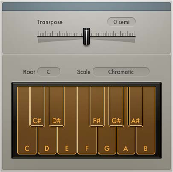
Chapter 9 MIDI plug-ins 195
Transposer MIDI plug-in
The Transposer MIDI plug-in can transpose incoming MIDI notes in real time and can correct
notes to a selected scale.
Transposer parameters
•Transpose slider: Drag to transpose incoming MIDI Notes by ± 24 semitones.
•Root pop-up menu: Choose the root note for the scale.
•Scale pop-up menu: Choose one of several preset scales or create your own custom scale (User)
with the onscreen keyboard.
•Keyboard: Click notes on the Keyboard to switch them on or o. Notes that are turned o are
excluded from the User scale.
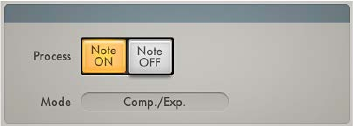
Chapter 9 MIDI plug-ins 19 6
Velocity Processor MIDI plug-in
Velocity Processor overview
The Velocity Processor MIDI plug-in processes incoming MIDI velocity events—note on and note
o—in real time. Among other applications, it allows velocity compression and expansion.
Velocity Processor global parameters
•Process buttons: Click either button to process MIDI note on velocity or MIDI note o velocity.
Click both buttons to process MIDI note on and MIDI note o velocity.
•Mode pop-up menu: Choose a velocity processing mode. The available parameters change
depending on the mode selected.
•Compress/Expand: In Velocity Processor Compress/Expand mode, the plug-in behaves like an
audio compressor.
•Value/Range: In Velocity Processor Value/Range mode, the plug-in behaves like an
audio limiter.
•Add/Scale: In Velocity Processor Add/Scale mode, the plug-in scales, adds to, or reduces the
values of incoming MIDI velocity messages.
•Input Min and Input Max sliders (extended parameter): Click the disclosure triangle at the lower
left to open the extended parameters. Move the Input Min and Input Max sliders to set an
input note range. Notes that fall within the input note range are processed (default range:
1–127). Notes outside the input note range are not processed.
Note: You can cross over the Input Min and Input Max sliders, which inverts the input note
range behavior: note events that fall within the range are not processed and note events
outside the range have their velocities processed.
•Range Learn checkbox (extended parameter): Click to turn on Learn mode, then play a (low)
key on your MIDI keyboard to set the Input Min value. Play a (high) key to set the Input
Max value.
Once both keys have been played, Learn mode is automatically turned o, and the Range
Learn checkbox is cleared.
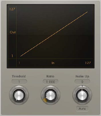
Chapter 9 MIDI plug-ins 197
Velocity Processor Compress/Expand mode
In Compress/Expand mode, the Velocity Processor MIDI plug-in behaves like an
audio compressor.
Compress/Expand mode parameters
•Threshold knob: Rotate to set a velocity value. Incoming velocities above the threshold are
processed. MIDI notes with velocity values below the threshold pass through unaected.
•Ratio knob: Rotate to determine the slope of compression/expansion above the threshold.
Processing is done using a “soft knee” characteristic.
•Ratios smaller than 1 result in an expansion of incoming velocity values.
•Ratios greater than 1 result in compression of incoming velocity values.
•Make-up knob: Rotate to set a velocity oset to compensate for the higher or lower overall
velocity caused by compression/expansion. The velocity oset can be positive or negative,
either adding to or subtracting from incoming velocity values.
•Auto (Gain) button: Turn on to automatically apply a maximum velocity reference level, set with
the Make-up knob.
Note: When the Auto button is active, the Make-up knob changes function: instead of setting
the velocity oset value, it sets the maximum velocity reference level.
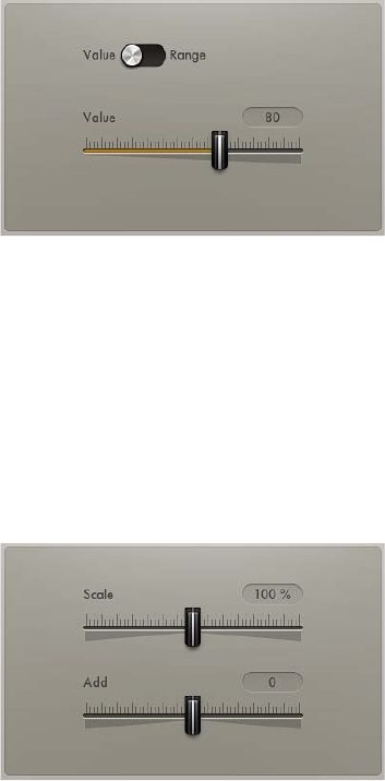
Chapter 9 MIDI plug-ins 19 8
Velocity Processor Value/Range mode
In Value/Range mode, the Velocity Processor MIDI plug-in can behave like an audio limiter.
Value/Range mode parameters
•Value/Range switch: Set to Value to limit all incoming MIDI velocity values to the value set with
the Value slider. Set to Range to limit all incoming MIDI velocity values to the range set with
the Min and Max sliders.
•Value slider: Drag to set a xed velocity for all processed notes.
Velocity Processor Add/Scale mode
In Add/Scale mode, the Velocity Processor MIDI plug-in scales, adds to, or reduces the values of
incoming MIDI velocity messages.
Add/Scale mode parameters
•Scale slider: Move to scale all incoming MIDI velocity values by a percentage from zero to 200%.
•Add slider: Move to add the set value to, or subtract it from, incoming MIDI velocity values.
19 9
Modulation eects overview
Modulation eects—such as chorus, anging, and phasing—are used to add motion and depth
to your sound.
Modulation eects typically delay the incoming signal by a few milliseconds and use an LFO
to modulate the delayed signal. The LFO may also be used to modulate the delay time in
some eects.
A low frequency oscillator (LFO) is similar to the sound-generating oscillators in synthesizers, but
the frequencies generated by an LFO are so low that they can’t be heard and are therefore used
only for modulation purposes. LFO parameters include speed (or frequency) and depth—also
called intensity—controls.
You can also control the ratio between the aected (wet) signal and the original (dry) signal.
Some modulation eects include feedback parameters, which add part of the eect’s output
back into the eect input.
Other modulation eects involve pitch. The most basic type of pitch modulation eect is vibrato,
which uses an LFO to modulate the frequency of the sound. Unlike other pitch modulation
eects, vibrato alters only the delayed signal.
More complex modulation eects, such as Ensemble, mix several delayed signals with the
original signal.
Modulation eects 10
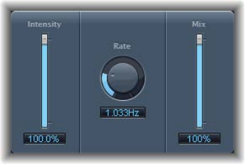
Chapter 10 Modulation eects 200
Chorus eect
The Chorus eect delays the original signal, and the delay time is modulated with an LFO. The
delayed, modulated signal is then mixed with the original, dry signal.
You can use the Chorus eect to enrich the incoming signal and create the impression that
multiple instruments or voices are being played in unison. The slight delay time variations
generated by the LFO simulate the subtle pitch and timing dierences heard when several
musicians or vocalists perform together. Using chorus also adds fullness or richness to the signal,
and it can add movement to low or sustained sounds.
Chorus parameters
•Intensity slider and eld: Drag to set the modulation amount.
•Rate knob and eld: Rotate to set the frequency, or speed, of the LFO.
•Mix slider and eld: Drag to determine the balance between dry and wet signals.
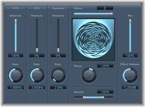
Chapter 10 Modulation eects 201
Ensemble eect
Ensemble can add richness and movement to sounds, particularly when you use a high number
of voices. It is useful for thickening parts, but you can also use it for strong pitch variations
between voices, resulting in a detuned quality to processed material. Ensemble combines up
to eight chorus eects. Two standard LFOs and one random LFO enable you to create complex
modulations. The graphic display visually represents what is happening with processed signals.
Ensemble parameters
•Intensity sliders and elds: Drag to set the amount of modulation for LFO 1, LFO 2, and
random modulation.
•Rate knobs and elds: Rotate to control the frequency of LFO 1, LFO 2, and random modulation.
•Voices slider and eld: Drag to determine how many individual chorus instances are used. This
setting determines the number of voices, or signals, that are generated in addition to the
original signal.
•Graphic display: Indicates the shape and intensity of the modulations.
•Phase knob and eld: Rotate to control the phase relationship between the individual voice
modulations. The value you choose here is dependent on the number of voices, which is why
it is shown as a percentage value rather than in degrees. The value 100 (or −100) indicates the
greatest possible distance between the modulation phases of all voices.
•Spread slider and eld: Drag to distribute voices across the stereo or surround eld. You can
set a value of 200% to articially expand the stereo or surround base. Note that monaural
compatibility may suer if you do this.
•Mix slider and eld: Drag to set the balance between dry and wet signals.
•Eect Volume knob and eld: Rotate to set the level of the eects signal. This is a useful tool that
compensates for changes in volume caused by changes to the Voices parameter.
Note: When you are using the Ensemble eect in surround, the input signal is converted to
mono before processing—that is, you insert the Ensemble eect as a multi-mono instance.
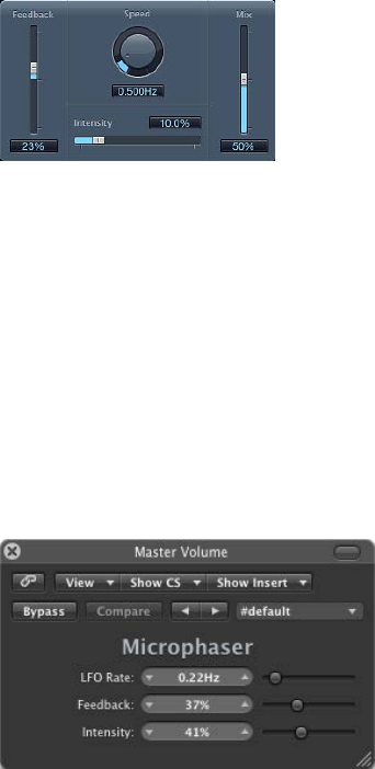
Chapter 10 Modulation eects 202
Flanger eect
The Flanger eect works in much the same way as the Chorus eect, but it uses a signicantly
shorter delay time. In addition, the eect signal can be fed back into the input of the delay line.
Flanging is typically used to add a spacey or underwater quality to input signals.
Flanger parameters
•Feedback slider and eld: Drag to set the amount of the eect signal that is routed back into
the input. This can change the tonal color and make the sweeping eect more pronounced.
Negative Feedback values invert the phase of the routed signal.
•Speed knob and eld: Rotate to set the frequency (speed) of the LFO.
•Intensity slider and eld: Drag to determine the modulation amount.
•Mix slider and eld: Drag to determine the balance between dry and wet signals.
Microphaser
Microphaser enables you to quickly create swooshing, phasing eects.
Microphaser parameters
•LFO Rate slider and eld: Drag to set the frequency (the speed) of the LFO.
•Feedback slider and eld: Drag to determine the amount of eect signal routed back into the
input. This can change the tonal color and make the sweeping eect more pronounced.
•Intensity slider and eld: Drag to determine the amount of modulation.
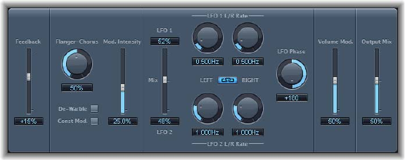
Chapter 10 Modulation eects 203
Modulation Delay
Modulation Delay is based on the same principles as the Flanger and Chorus eects, but you can
set the delay time, allowing both chorus and anging eects to be generated. It can also be used
without modulation to create resonator or doubling eects. The modulation section consists of
two LFOs with variable frequencies.
Although rich, combined anging and chorus eects are possible, the Modulation Delay is
capable of producing some extreme modulation eects. These include emulations of tape speed
uctuations and metallic, robot-like modulations of incoming signals.
Modulation Delay parameters
•Feedback slider and eld: Drag to set the amount of eect signal routed back to the input.
Use a high Feedback value for strong modulations. If you want to double the signal, don’t
use Feedback. Negative values invert the phase of the feedback signal, resulting in more
chaotic eects.
•Flanger-Chorus knob and eld: Rotate to set the basic delay time. Set to the far left position
to create anger eects, to the center for chorus eects, and to the far right to hear clearly
discernible delays.
•De-Warble button: Turn on to make sure the pitch of the modulated signal remains constant.
•Const(ant) Mod(ulation) button: Turn on to make sure the modulation width remains constant,
regardless of the modulation rate.
Note: When Const Mod is enabled, higher modulation frequencies reduce the modulation
width.
•Mod(ulation) Intensity slider and eld: Drag to set the modulation amount.
•LFO Mix slider and elds: Drag to determine the balance between the two LFOs.
•LFO 1 and LFO 2 Rate knobs and elds: Rotate to set the modulation rate for the left and right
stereo channels. In surround instances, the center channel is assigned the middle value of the
left and right LFO Rate knobs. The other channels are assigned values between the left and
right LFO rates.
Note: The right LFO Rate knob is available only in stereo and surround instances, and it can be
set separately only if the Left Right Link button is not enabled.
•LFO Left Right Link button: Turn on to link the modulation rates of the left and right stereo
channels. Adjustment of either Rate knob will aect the other channel in stereo instances, or
other channels in surround instances.
Chapter 10 Modulation eects 204
•LFO Phase knob and eld: Rotate to control the phase relationship between individual channel
modulations. Available only in stereo and surround instances.
•At 0°, the extreme values of the modulation are achieved simultaneously for all channels.
•At 180° or −180°, you achieve the greatest possible distance between the modulation phases
of the channels.
Note: The LFO Phase parameter is available only if the LFO Left Right Link button is active.
•Distribution pop-up menu: Choose how phase osets between individual channels are
distributed in the surround eld: “circular,” “left↔right,” “front↔rear,” “random,” or “new random.”
Available only in surround instances.
Note: When you load a setting that uses the “random” option, the saved phase oset value
is recalled. If you want to randomize the phase setting again, choose “new random” from the
Distribution pop-up menu.
•Volume Mod(ulation) slider and eld: Drag to determine the impact of LFO modulation on the
amplitude of the eect signal.
•Output Mix slider and eld: Drag to determine the balance between dry and wet signals.
•All Pass button (Extended Parameters area): Turn on to introduce an additional allpass lter into
the signal path. An allpass lter shifts the phase angle of a signal, inuencing its stereo image.
•All Pass Left and All Pass Right sliders and elds (Extended Parameters area): Drag to determine
the frequency at which the phase shift crosses 90°—the halfway point of the total 180°—for
each of the stereo channels. In surround instances, the other channels are automatically
assigned values that fall between the two settings.
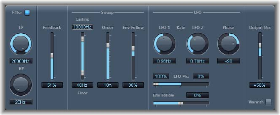
Chapter 10 Modulation eects 205
Phaser eect
The Phaser eect combines the original signal with a copy that is slightly out of phase with the
original. This means that the amplitudes of the two signals reach their highest and lowest points
at slightly dierent times. The timing dierences between the two signals are modulated by two
independent LFOs. In addition, the Phaser includes a lter circuit and a built-in envelope follower
that tracks volume changes in the input signal, generating a dynamic control signal. This control
signal alters the sweep range.
Sonically, phasing is used to create whooshing, sweeping sounds that wander through the
frequency spectrum. It is a commonly used guitar eect, but it is suitable for a range of signals.
Phaser parameters
•Filter button: Turns the lter section on or o, which processes the feedback signal.
•LP and HP knobs and elds: Rotate to set the cuto frequency of the lowpass (LP) and highpass
(HP) lters.
•Feedback slider and eld: Drag to determine the amount of eect signal routed back into
the input.
•Ceiling and Floor sliders and elds: Drag to determine the frequency range aected by the LFO
modulations. Drag the blue area to move the entire range.
•Order slider and eld: Drag to choose phaser algorithms. The more orders, the stronger
the eect.
•The 4, 6, 8, 10, and 12 settings switch between ve dierent phaser algorithms. All are
modeled on analog circuits, with each designed for a specic application.
•The odd-numbered settings (5, 7, 9, and 11) don’t generate actual phasing eects. The more
subtle comb ltering eects produced by odd-numbered settings can, however, be useful.
•Env Follow slider and eld: Drag to determine the impact of incoming signal levels on the
frequency range (set with the Ceiling and Floor controls).
•LFO 1 and LFO 2 Rate knobs and elds: Rotate to set the speed for each LFO.
•LFO Mix slider and elds: Drag to determine the ratio between the two LFOs.
•Env Follow slider and eld: Drag to determine the impact of incoming signal levels on the speed
of LFO 1.
•Phase knob and eld: Rotate to control the phase relationship between the individual channel
modulations. Available only in stereo and surround instances. At 0°, the extreme values of the
modulation are achieved simultaneously for all channels. At 180° or −180°, there is the greatest
possible distance between the modulation phases of the channels.
•Distribution pop-up menu: Choose how phase osets between individual channels are
distributed in the surround eld: “circular,” “left↔right,” “front↔rear,” “random,” or “new random.”
Available only in surround instances.
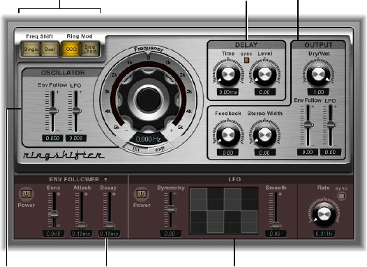
Chapter 10 Modulation eects 206
Note: When you load a setting that uses the “random” option, the saved phase oset value
is recalled. If you want to randomize the phase setting again, choose “new random” from the
Distribution pop-up menu.
•Output Mix slider and eld: Determines the balance of dry and wet signals. Negative values
result in a phase-inverted mix of the eect and direct (dry) signal.
•Warmth button: Click to turn on a distortion circuit, which is suitable for warm overdrive eects.
Ringshifter
Ringshifter overview
Ringshifter combines a ring modulator with a frequency shifter eect. Both eects were popular
during the 1970s and are currently experiencing a renaissance.
The ring modulator modulates the amplitude of the input signal using either the internal
oscillator or a side-chain signal. The frequency spectrum of the resulting eect signal equals the
sum of, and the dierence between, the frequency content in the two original signals. Its sound
is often described as metallic or clangorous.
The frequency shifter moves the frequency content of the input signal by a xed amount and
thereby alters the frequency relationship of the original harmonics. The resulting sounds range
from sweet and spacious phasing eects to robot-like timbres.
Note: Do not confuse frequency shifting with pitch shifting. Pitch shifting transposes the original
signal, leaving its harmonic frequency relationship intact.
Ringshifter interface
The Ringshifter interface consists of six main sections.
Output parameters
Delay parameters
Mode buttons
Envelope follower
parameters
LFO parametersOscillator
parameters
•Mode buttons: Determine whether Ringshifter operates as a frequency shifter or a ring
modulator. See Set the Ringshifter mode on page 207.
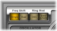
Chapter 10 Modulation eects 207
•Oscillator parameters: Congure the internal sine wave oscillator, which modulates the
amplitude of the input signal in both of the frequency shifter modes as well as in the ring
modulator OSC mode. See Ringshifter oscillator parameters on page 208.
•Delay parameters: Delay the eect signal. See Ringshifter delay parameters on page 209.
•Envelope follower parameters: Modulate the oscillator frequency and output signal with an
envelope follower. See Ringshifter envelope follower modulation on page 209.
•LFO parameters: Modulate the oscillator frequency and output signal with an LFO. See
Ringshifter LFO modulation on page 210.
•Output parameters: Set feedback, stereo width, and the amount of dry and wet signals. See
Ringshifter output parameters on page 211.
Set the Ringshifter mode
The four mode buttons determine whether the Ringshifter operates as a frequency shifter or as a
ring modulator.
Ringshifter mode parameters
•Single Freq(uency) Shift(er) button: The frequency shifter generates a single, shifted eect signal.
The oscillator Frequency control determines whether the signal is shifted to a positive value
on the right side of the Frequency knob or to a negative value on the left side.
•Dual Freq(uency) Shift(er) button: Produces one shifted eect signal for each stereo channel—
one is shifted up, the other is shifted down.
The oscillator Frequency control determines the shift direction towards the left or the
right channel.
•OSC Ring Mod(ulator) button: The ring modulator uses the internal sine wave oscillator to
modulate the input signal.
•Side Chain Ring Mod(ulator) button: The ring modulator modulates the amplitude of the input
signal with the audio signal assigned via the side-chain input.
The sine wave oscillator is switched o, and the Frequency controls are disabled when Side
Chain mode is active.
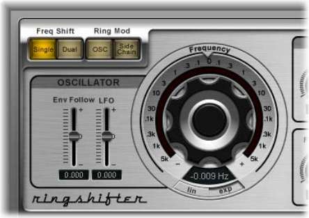
Chapter 10 Modulation eects 208
Ringshifter oscillator parameters
In both of the frequency shifter modes as well as in the ring modulator OSC mode, the internal
sine wave oscillator is used to modulate the amplitude of the input signal.
•In the frequency shifter modes, the Frequency parameter controls the amount of frequency
shifting, either up or down, applied to the input signal.
•In the ring modulator OSC mode, the Frequency parameter controls the frequency content, or
timbre, of the resulting eect. This timbre can range from subtle tremolo eects to clangorous
metallic sounds.
Oscillator parameters
•Frequency control: Rotate to set the frequency of the sine oscillator.
•Lin(ear) and Exp(onential) buttons: Switch the scaling of the Frequency control:
•Lin(ear): Linear scaling is even across the entire control range.
•Exp(onential): Exponential scaling oers extremely small increments around the 0 point,
which is useful for programming slow-moving phasing and tremolo eects.
•Env(elope) Follow slider and eld: Drag to determine the impact of incoming signal levels on the
oscillator modulation depth.
•LFO slider and eld: Drag to determine the amount of oscillator modulation by the LFO.
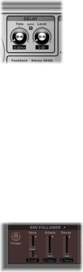
Chapter 10 Modulation eects 209
Ringshifter delay parameters
The eect signal is routed through a delay, following the oscillator.
Delay parameters
•Time knob and eld: Rotate to set the delay time—in Hz when running freely, or in note values,
including triplet and dotted notes, when the Sync button is selected.
•Sync button: Turn on to synchronize the delay to the host application tempo. You can choose
musical note values with the Time knob.
•Level knob and eld: Rotate to set the level of the delay added to the ring-modulated or
frequency-shifted signal. A Level value of 0 passes the eect signal directly to the output
(bypass).
Ringshifter modulation
Ringshifter envelope follower modulation
The oscillator Frequency and Dry/Wet parameters can be modulated with the internal envelope
follower—and the LFO (see Ringshifter LFO modulation on page 210). The oscillator frequency
even allows modulation through the 0 Hz point, thus changing the oscillation direction.
The envelope follower analyzes the amplitude (volume) of the input signal to create a
continuously changing control signal—a dynamic volume envelope of the input signal. This
control signal can be used for modulation purposes.
Envelope Follower parameters
•Power button: Turns the envelope follower on or o. When it is turned on, you can access the
following parameters:
•Sens(itivity) slider and eld: Drag to determine how responsive the envelope follower is to the
input signal. At lower settings, the envelope follower reacts only to the most dominant signal
peaks. At higher settings, the envelope follower tracks the signal more closely but may react
less dynamically.
•Attack slider and eld: Drag to set the response time of the envelope follower.
•Decay slider and eld: Drag to set the time it takes the envelope follower to return from a
higher to a lower value.
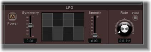
Chapter 10 Modulation eects 210
Ringshifter LFO modulation
The oscillator Frequency and Dry/Wet parameters can be modulated with the LFO—and the
envelope follower (see Ringshifter envelope follower modulation on page 209). The oscillator
frequency even allows modulation through the 0 Hz point, thus changing the oscillation
direction. The LFO produces continuous, cycled control signals.
Ringshifter LFO parameters
•Power button: Turns the LFO on or o. When it is turned on, you can access the following
parameters.
•Symmetry and Smooth sliders and elds: Drag to change the shape of the LFO waveform.
•Waveform display: Provides visual feedback about the LFO waveform shape.
•Rate knob and eld: Rotate to set the waveform cycle speed of the LFO.
•Sync button: Turn on to synchronize the LFO rate with the host application tempo, using
musical note values.
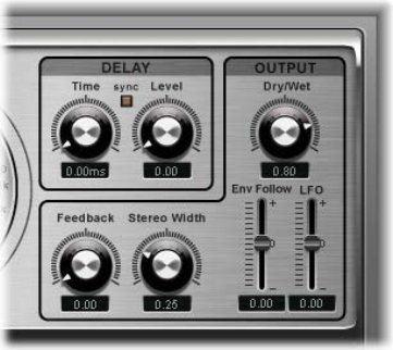
Chapter 10 Modulation eects 211
Ringshifter output parameters
The output parameters are used to set the balance between the eect and input signals and also
to set the width and feedback level of the Ringshifter.
Ringshifter Output parameters
•Dry/Wet knob and eld: Rotate to set the mix ratio of the dry input signal and the wet
eect signal.
•Feedback knob and eld: Rotate to set the amount of signal routed back to the eect input.
Feedback adds an edge to the Ringshifter sound and is used for a variety of special eects.
•Feedback, in combination with a slow oscillator sweep, produces a rich phasing sound.
•A high Feedback setting with a short delay time of less than 10 ms produces
comb-ltering eects.
•A high Feedback setting with a longer delay time produces continuously rising and falling
frequency shift eects.
•Stereo Width knob and eld: Rotate to determine the breadth of the eect signal in the stereo
eld. Stereo Width aects only the eect signal of the Ringshifter, not the dry input signal.
•Env(elope) Follower slider and eld: Drag to determine the amount of Dry/Wet parameter
modulation by the input signal level.
•LFO slider and eld: Drag to set the LFO modulation depth of the Dry/Wet parameter.
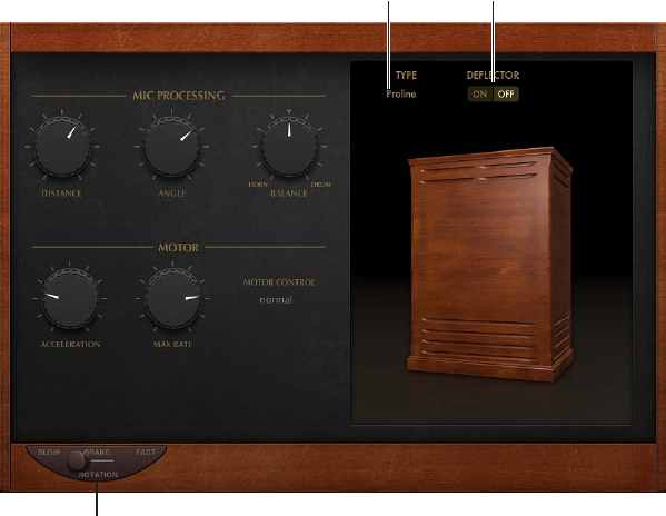
Chapter 10 Modulation eects 212
Rotor Cabinet eect
Rotor Cabinet eect overview
The Rotor Cabinet eect emulates the rotating loudspeaker cabinet of a Hammond organ.
Also known as the Leslie eect, it simulates both the rotating speaker cabinet, with and without
deectors, and the microphones that pick up the sound.
Rotation switch
Deflector switch
Click to choose a
cabinet type.
Basic Rotor Cabinet parameters
•Rotation switch: Move to change the rotor speed between Slow, Brake, or Fast.
•(Cabinet) Type pop-up menu: Click to choose a cabinet model:
•Wood: Mimics a Leslie with a wooden enclosure, sounding like the Leslie 122 or 147 model.
•Proline: Mimics a Leslie with a more open enclosure, similar to a Leslie 760 model.
•Single: Simulates the sound of a Leslie with a single, full-range rotor, sounding like the
Leslie 825 model.
•Split: Routes the bass rotor’s signal slightly to the left and the treble rotor’s signal toward
the right.
•Wood & Horn IR: Uses an impulse response of a Leslie with a wooden enclosure.
•Proline & Horn IR: Uses an impulse response of a Leslie with a more open enclosure.
•Split & Horn IR: Uses an impulse response of a Leslie with the bass rotor signal routed slightly
to the left and the treble rotor signal routed more to the right.
•Deector switch: Emulates a Leslie cabinet with the horn deectors removed or attached.
A Leslie cabinet contains a double horn, with a deector at the horn mouth. This deector
makes the Leslie sound. You can remove the deector to increase amplitude modulation and
decrease frequency modulation.
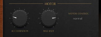
Chapter 10 Modulation eects 213
Rotor Cabinet eect motor parameters
The Rotor Cabinet eect provides the following motor control parameters.
Motor parameters
•Acceleration knob: Rotate to set the time it takes to get the rotors up to the speed set with
the Max Rate knob, and the length of time it takes for them to slow down. The Leslie motors
need to physically accelerate and decelerate the speaker horns in the cabinets, and their
power to do so is limited. Turn Acceleration to the far left position to switch to the preset
speed immediately. As you rotate the knob to the right, it takes more time to hear the speed
changes. At the default, centered, position the behavior is Leslie-like.
•Max Rate knob: Rotate to set the maximum possible rotor speed.
•Motor Control pop-up menu: Set dierent speeds for the bass and treble rotors in the pop-up
menu. Use the Rotation switch to choose slow, brake, or fast mode.
•Normal: Both rotors use the speed determined by the Rotation switch position.
•Inv (inverse): In fast mode, the bass compartment rotates at a fast speed, while the horn
compartment rotates slowly. This is reversed in slow mode. In brake mode, both rotors stop.
•910: The 910 (also known as “Memphis”), stops the bass drum rotation at slow speed, while
the speed of the horn compartment can be switched. This is useful when you’re after a solid
bass sound but still want treble movement.
•Sync: The acceleration and deceleration of the horn and bass drums are roughly the same.
This sounds as if the two drums are locked, but the eect is clearly audible only during
acceleration or deceleration.
Note: If you choose Single Cabinet from the (Cabinet) Type pop-up menu, the Motor Control
setting is not relevant because there are no separate bass and treble rotors in a single cabinet.
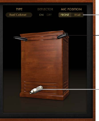
Chapter 10 Modulation eects 214
Rotor Cabinet eect microphone types
The Rotor Cabinet eect provides modeled microphones that pick up the sound of the Leslie
cabinet. You can specify the microphone type with these parameters. Also see Rotor Cabinet
eect mic processing controls.
Click to choose a
microphone type.
Click to choose a
microphone type.
Mic Position switch
Click the microphone icons to choose a microphone type for the horn and drum speakers when
Real Cabinet is chosen in the Type pop-up menu. See Rotor Cabinet eect overview.
•Dynamic: Emulates the sound of a dynamic cardioid microphone. This microphone type
sounds brighter and more cutting than the Condenser mic.
•Condenser: Emulates the sound of a studio condenser microphone. The sound of condenser
microphones is ne, transparent, and well-balanced.
•Mid-Side Mic: A Middle and Side (MS) conguration where two microphones are positioned
closely together. One is a cardioid (or omnidirectional) microphone that directly faces the
cabinet—in a straight alignment. The other is a bidirectional microphone, with its axes
pointing to the left and right of the cabinet at 90° angles. The cardioid microphone captures
the middle signal to one stereo side. The bidirectional microphone captures the side signal to
the other stereo side.
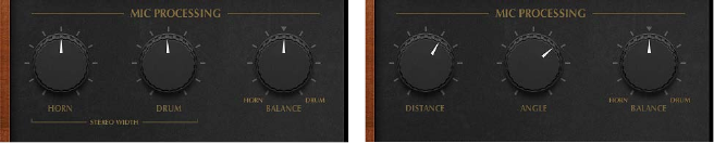
Chapter 10 Modulation eects 215
Rotor Cabinet eect mic processing controls
The Rotor Cabinet eect provides the following microphone processing parameters.
Mic processing parameters
•Mic Position switch: Choose either the front or rear position for the virtual microphone. See
Rotor Cabinet eect microphone types.
•When Real Cabinet is chosen in the Type pop-up menu:
•Horn knob: Rotate to dene the stereo width of the Horn deector microphone.
•Drum knob: Rotate to dene the stereo width of the Drum deector microphone.
•When other cabinets are chosen in the Type pop-up menu:
•Distance knob: Rotate to determine the distance of the virtual microphones (the listening
position) from the emulated speaker cabinet. Turn to the right for a darker and less
dened sound.
•Angle knob: Rotate to dene the stereo image, by changing the angle of the simulated
microphones between 0 and 180 degrees.
•Balance knob: Rotate to set the balance between the horn and drum microphone signals.
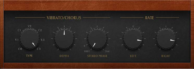
Chapter 10 Modulation eects 216
Scanner Vibrato eect
Scanner Vibrato simulates the scanner vibrato section of a Hammond organ. Scanner Vibrato is
based on an analog delay line consisting of several lowpass lters. The delay line is scanned by a
multipole capacitor that has a rotating pickup. It is a unique eect that cannot be simulated with
simple LFOs.
You can choose between three dierent vibrato and chorus types. The stereo version of the eect
features two additional parameters—Stereo Phase and Rate Right. These allow you to set the
modulation speed independently for the left and right channels.
Scanner Vibrato parameters
•Type knob: Rotate to choose from three Vibrato positions (V1, V2, and V3) or three Chorus
positions (C1, C2, and C3).
•In each of the Vibrato positions, only the delay line signal is heard. Each vibrato type has a
dierent intensity.
•In the three Chorus positions (C1, C2, and C3), the signal of the delay line is mixed with the
original signal. Mixing a vibrato signal with an original, statically pitched signal results in a
chorus eect. This organ-style chorus sounds dierent from the Chorus plug-in.
•In the C0 setting, neither the chorus nor the vibrato is enabled.
•Depth knob: Rotate to set the intensity of the chosen chorus eect type. If a vibrato eect type
is chosen, this parameter has no eect.
•Stereo Phase knob: Rotate to determine the phase relationship between left and right channel
modulations. If you set the knob to free, you can set the modulation speed of the left and right
channels independently.
•Rate Left knob: Rotate to set the modulation speed of the left channel when Stereo Phase is
set to free. If Stereo Phase is set to a value between 0° and 360°, Rate Left sets the modulation
speed for both the left and right channels. The Rate Right knob has no function when in
this mode.
•Rate Right knob: Rotate to set the modulation speed of the right channel when Stereo Phase is
set to free.
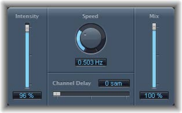
Chapter 10 Modulation eects 217
Spreader
Spreader widens the stereo spectrum of a signal by periodically shifting the frequency range of
the original signal, thus changing the perceived width of the signal. You can also use Spreader to
specify the delay between channels in samples, which adds to the perceived width and channel
separation of a stereo input signal.
Spreader parameters
•Intensity slider and eld: Drag to determine the modulation amount.
•Speed knob and eld: Rotate to set the speed of the built-in LFO.
•Channel Delay slider and eld: Drag to set the delay time in samples.
•Mix slider and eld: Drag to determine the balance between the eect and input signals.
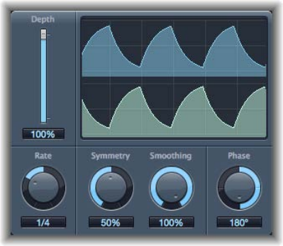
Chapter 10 Modulation eects 218
Tremolo eect
Tremolo modulates the amplitude of the incoming signal, resulting in periodic volume changes.
Tremolo is commonly used in vintage guitar combo amps, where it is sometimes incorrectly
referred to as vibrato. The graphic waveform display shows all the parameters except Rate.
Tremolo parameters
•Depth slider and eld: Drag to determine the modulation amount.
•Waveform display: Shows the resulting waveform.
•Rate knob and eld: Rotate to set the frequency of the LFO.
•Symmetry and Smoothing knobs and elds: Rotate to change the shape of the LFO waveform.
If Symmetry is set to 50% and Smoothing to 0%, the LFO waveform becomes rectangular. The
timing of the highest volume signal is then equal to the timing of the lowest volume signal,
with the switch between both states occurring abruptly.
•Phase knob and eld: Rotate to control the phase relationship between individual channel
modulations in stereo or surround signals. At 0, modulation values are reached simultaneously
for all channels. At values of 180 or −180, there is the greatest possible distance between the
modulation phases of the channels.
•Distribution pop-up menu: Choose how phase osets between individual channels are
distributed in the surround eld: “circular,” “left↔right,” “front↔rear,” “random,” or “new random.”
Available only in surround instances.
•Oset slider and eld (Extended Parameters area): Drag to set the amount that the modulation
(cycle) is shifted to the left or right, resulting in subtle or signicant tremolo variations.
219
Pitch eects overview
You can use the pitch eects to transpose or correct the pitch of audio signals. These eects can
also be used for creating unison or slightly thickened parts, or even for creating harmony voices.
You can also dene a scale to automatically correct some, but not all, sung notes in a vocal
performance, for example. This enables you to eectively perfect an imperfect vocal take.
You can also use pitch correction eects creatively, modifying all pitched notes in a performance
to a single pitch or a particular key.
Pitch Correction eect
Pitch Correction eect overview
You can use the Pitch Correction eect to x the pitch of incoming audio signals. Improper
intonation is a common problem with vocal tracks, for example. The sonic artifacts that can be
introduced by the process are minimal and are almost silent when making moderate corrections.
Pitch correction works by accelerating and slowing down the audio playback speed, matching
the input signal (sung vocal) with the correct note pitch. If you try to correct larger intervals, you
can create special eects. Natural articulations of the performance, such as breath noises, are
preserved.
Any scale can be dened as a pitch reference (technically speaking, this is known as a pitch
quantization grid). Improperly intonated notes are corrected in accordance with this scale.
The Pitch Correction eect can be fully automated. This means that you can automate the Scale
and Root parameters to follow harmonies in the project. Depending on the accuracy of the
original intonation, setting the appropriate key with the Scale parameter may suce. Less precise
intonations may need more signicant changes to the Scale and Root parameters.
Note: Polyphonic recordings, such as choirs, and highly percussive signals with prominent noisy
portions cannot be corrected to a specic pitch. Despite this, you may want to try the plug-in on
some drum sounds, such as toms and congas because it can deliver interesting results.
Pitch eects 11
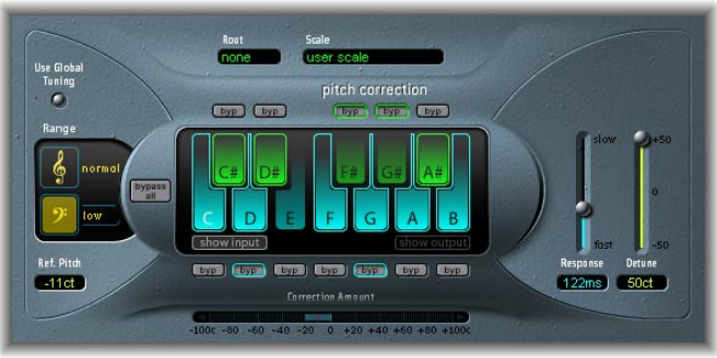
Chapter 11 Pitch eects 220
Pitch Correction eect parameters
Pitch Correction parameters
•Use Global Tuning button: Turn on to use project Tuning settings for the pitch correction
process. Turn o to set the reference tuning with Ref. Pitch. See Use Pitch Correction eect
reference tuning on page 223.
•Normal and low buttons: Click to set the pitch range that is scanned (for notes that need
correction). See Pitch Correction eect quantization grid on page 221.
•Ref. Pitch eld: Drag to set the reference tuning in cents (relative to the root).
•Root pop-up menu: Choose the root note of the scale.
•Scale pop-up menu: Choose a pitch quantization grid.
•Keyboard: Click a key to exclude the corresponding note from pitch quantization grids. This
eectively removes this key from the scale, resulting in note corrections that are forced to the
nearest available pitch (key). See Exclude notes from pitch correction on page 222.
•Byp(ass) buttons: Click to exclude the corresponding note from pitch correction. In other words,
all notes that match this pitch will not be corrected. This applies to both user and built-in scale
quantization grids.
•Bypass All button: Click to quickly compare the corrected and original signals or to audition
automation changes.
•Show input and show output buttons: Click to show the pitch of the input or output signal,
respectively, on the notes of the keyboard.
•Correction Amount display: Indicates the amount of pitch change. The red marker indicates the
average correction amount over a longer time period. You can use the display when discussing
(and optimizing) the vocal intonation with a singer during a recording session.
•Response slider and eld: Drag to determine how quickly the voice reaches the corrected
destination pitch.
Singers use portamenti and other gliding techniques. If you choose a Response value that’s
too high, seamless portamenti turn into semitone-stepped glissandi, but the intonation will be
perfect. If the Response value is too low, the pitch of the output signal won’t change quickly
enough. The optimum setting for this parameter depends on the singing style, tempo, vibrato,
and accuracy of the original performance.
•Detune slider and eld: Drag to detune the output signal by the set value.
Chapter 11 Pitch eects 221
Pitch Correction eect quantization grid
Use the Pitch Correction eect’s “normal” and “low” buttons to determine the pitch range that
you want to scan for notes that need correction. Normal is the default range and works for
most audio material. Low should be used only for audio material that contains extremely low
frequencies (below 100 Hz), which may result in inaccurate pitch detection. These parameters
have no eect on the sound; they are simply optimized tracking options for the chosen target
pitch range.
The Scale pop-up menu allows you to choose dierent pitch quantization grids. The default
setting is the chromatic scale.
The user scale is the scale that is set manually with the onscreen keyboard in the plug-in window.
If you’re unsure of the intervals used in any given scale, choose it from the Scale pop-up menu
and look at the onscreen keyboard. You can alter any note in the chosen scale by clicking the
keyboard keys. Any such adjustments overwrite the existing user scale settings.
There is only one user scale per project. You can, however, create multiple user scales and save
them as Pitch Correction plug-in settings les.
Tip: The drone scale uses a fth as a quantization grid, and the single scale denes a single note.
Neither of these scales is meant to result in realistic singing voices, but you should try them if
aiming for interesting eects.
Choose the root note of the scale from the Root pop-up menu. You can freely transpose the
major and minor scales and scales named after chords.
Note: If you choose user “scale” or “chromatic” from the Scale pop-up menu, the Root pop-up
menu entries are dimmed.
Chapter 11 Pitch eects 222
Exclude notes from pitch correction
You can use the Pitch Correction eect’s onscreen keyboard to exclude notes from the pitch
quantization grid.
When you rst open the eect, all notes of the chromatic scale are selected. This means that
every incoming note is altered to t the next semitone step of the chromatic scale. If the
intonation of the singer is poor, this might lead to notes being incorrectly identied and
corrected to an unwanted pitch. For example, the singer may have intended to sing an E, but the
note is actually closer to a D#. If you do not want the D# in the song, the D# key can be disabled
on the keyboard. Because the original pitch was sung closer to an E than a D, it is corrected to an
E.
Note: The settings made with the Pitch Correction eect’s onscreen keyboard are valid for all
octave ranges. Individual settings for dierent octaves are not provided.
Bypass individual notes in a scale
mTo exclude notes from correction, click the small bypass buttons (“byp”) above the green (black)
and below the blue (white) keys.
This is particularly useful for “blue” notes. Blue notes are notes that slide between pitches, making
the major and minor status of the keys dicult to identify. As you may know, one of the major
dierences between C minor and C major is the Eb (E at) and Bb (B at), instead of the E and B.
Blues singers glide between these notes, creating an uncertainty or tension between the scales.
Use of the bypass buttons allows you to exclude particular keys from changes, leaving them as
they were.
Tip: You will often nd that it’s best to correct only the notes with the most harmonic gravity. For
example, choose “sus4” from the Scale pop-up menu, and set the Root note to match the project
key. This limits correction to the root note, the fourth, and the fth of the key scale. Turn on the
bypass buttons for all other notes and only the most important and sensitive notes are corrected,
while all other singing remains untouched.
Bypass all pitch correction
Not all audio material can be eectively pitch corrected. In some cases, you may need to
use Logic Pro’s pitch manipulation and automation features to process a portion of an
audio performance.
mClick the bypass all button, to pass the input signal through unprocessed and uncorrected.
This is useful for spot corrections to pitch through use of automation. Bypass all is optimized for
near-instant, seamless operation in all situations.
Chapter 11 Pitch eects 223
Use Pitch Correction eect reference tuning
Turn on the Use Global Tuning button to use your host application Tuning settings for the pitch
correction process. This ensures that all software instruments and your tuned vocal part will be in
tune with each other.
If Use Global Tuning is turned o, you can use the Ref. Pitch eld to set the reference tuning to
the root key or note.
As an example of where Ref. Pitch can be eective, consider that the intonation of a vocal line is
often slightly sharp or at throughout an entire song. You can use Ref. Pitch to address this issue
at the input of the pitch detection process by setting it to reect the constant pitch deviation in
cent values. This allows the pitch correction to perform more accurately.
Note: Tunings that dier from software instrument tuning can be interesting when you want
to individually correct the notes of singers in a choir. If all voices are individually and perfectly
corrected to the same pitch, the choir eect is partially lost. You can prevent this by (de)tuning
the pitch corrections individually.
Set your host application reference tuning
Do one of the following:
mIn Logic Pro: To determine the tuning reference for all software instruments, choose File > Project
Settings > Tuning.
mIn MainStage: To determine the tuning reference for all software instruments, choose MainStage
> Preferences > Tuning, then open the General tab.
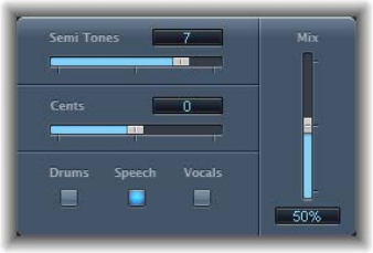
Chapter 11 Pitch eects 224
Pitch Shifter
Pitch Shifter overview
Pitch Shifter provides a simple way to combine a pitch-shifted version of the signal with the
original signal. Use pitch shifting to achieve the best results.
•Semi Tones slider and eld: Drag to set the pitch shift value in semitones.
•Cents slider and eld: Drag to control detuning of the pitch shift value in cents (1/100th of a
semitone).
•Drums, Speech, and Vocals buttons: Set one of three optimized algorithms for common types of
audio material. Choose from:
•Drums: Maintains the groove (rhythmic feel) of the source signal.
•Speech: Provides a balance between both the rhythmic and harmonic aspects of the signal.
This is suitable for complex signals such as spoken-word recordings, rap music, and other
hybrid signals such as rhythm guitar.
•Vocals: Retains the intonation of the source, making it well-suited for signals that are
inherently harmonic or melodious, such as string pads.
•Mix slider and eld: Drag to set the balance between the eect and original signals.
•Timing pop-up menu (Extended Parameters area): Choose how timing is derived:
•Preset: Follows the selected algorithm.
•Auto: Analyzes incoming audio.
•Manual: Uses the settings of the Delay, Crossfade, and Stereo Link parameters.
Note: The following three parameters are active only when Manual is chosen from the Timing
pop-up menu.
•Delay slider and eld (Extended Parameters area): Drag to set the amount of delay applied to the
input signal. The lower the frequencies of the input signal, the higher (longer) a delay time you
should set—to eectively pitch shift the signal.
•Crossfade slider and eld (Extended Parameters area): Drag to set the range (expressed as a
percentage of the original signal) used to analyze the input signal.
•Stereo Link buttons (Extended Parameters area): Click Inv. to invert the stereo channel’s signals,
with processing for the right channel occurring on the left, and vice versa. Click Normal to
leave the signal as it is.
Chapter 11 Pitch eects 225
Use Pitch Shifter
Pitch Shifter is used most eectively when you take a structured approach.
Use pitch shifting
1 To set the amount of transposition, or pitch shift, drag the Semi Tones slider.
2 To set the amount of detuning, drag the Cents slider.
3 To select the algorithm that best matches the material you are working with, click the Drums,
Speech, or Vocals button.
If you are working with material that does not t any of these categories, experiment with each
of the algorithms (starting with Speech), then compare the results and use the one that best
suits your material.
Tip: While auditioning and comparing dierent settings, temporarily set the Mix parameter to
100% because this makes Pitch Shifter II artifacts easier to hear.
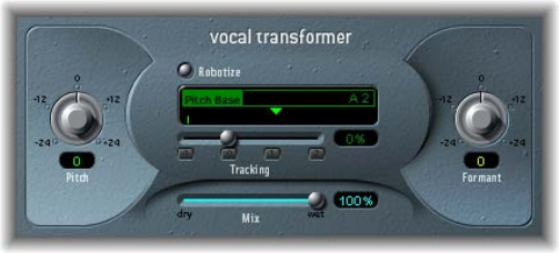
Chapter 11 Pitch eects 226
Vocal Transformer
Vocal Transformer overview
Vocal Transformer can be used to transpose the pitch of a vocal line, to augment or diminish the
range of the melody, or even to reduce it to a single note that mirrors the pitches of a melody.
No matter how you change the pitches of the melody, the constituent parts of the signal
(formants) remain the same.
You can shift the formants independently, which means that you can turn a vocal track into a
Mickey Mouse voice, while maintaining the original pitch. Formants are characteristic emphases
of certain frequency ranges. They are static and do not change with pitch. Formants are
responsible for the specic timbre of a given human voice.
Vocal Transformer is well suited to extreme vocal eects. The best results are achieved with
monophonic signals, including monophonic instrument tracks. It is not designed for polyphonic
voices—such as a choir on a single track—or other chordal tracks.
Vocal Transformer parameters
Vocal Transformer includes the following parameters.
Vocal Transformer parameters
•Pitch knob and eld: Rotate to determine the amount of transposition applied to the input
signal. See Use the Vocal Transformer Pitch and Formant parameters.
•Robotize button: Turns Robotize mode on or o. This mode is used to augment, diminish, or
mirror the melody. See Use Vocal Transformer’s Robotize mode.
•Pitch Base slider and eld: Available only in Robotize mode. Drag to transpose the note that the
Tracking parameter is following.
•Tracking slider, eld, and buttons: Available only in Robotize mode. Drag to control how the
melody is changed.
•Mix slider and eld: Drag to dene the level ratio between the original (dry) and eect signals.
•Formant knob and eld: Rotate to shift the formants of the input signal. See Use the Vocal
Transformer Pitch and Formant parameters.
•Glide slider and eld (Extended Parameters area): Drag to determine the time vocal
transformation takes, allowing sliding transitions to the set Pitch value.
•Grain Size slider and eld (Extended Parameters area): The Vocal Transformer eect algorithm is
based on granular synthesis. The Grain Size parameter allows you to set the size of the grains
and thus aect the precision of the process. Experiment to nd the best setting. Try Auto rst.
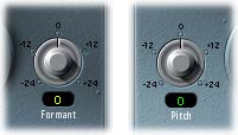
Chapter 11 Pitch eects 227
•Formants pop-up menu (Extended Parameters area): Choose how Vocal Transformer
processes formants.
•Process always: All formants are processed.
•Keep unvoiced formants: Only voiced formants are processed. This retains sibilant sounds
in a vocal performance and produces a more natural-sounding transformation eect with
some signals.
•Detune slider and eld (Extended Parameters area): Drag to detune the input signal by the set
value. This parameter is of particular benet when automated.
Use Vocal Transformer
You can change the pitch of performances, inclusive of, or independent from, formants. Robotize
mode enables you to augment or diminish the melody.
Use the Vocal Transformer Pitch and Formant parameters
mTo transpose the pitch of the signal upward or downward: Rotate the Pitch knob. Adjustments
are made in semitone steps. Incoming pitches are indicated by a vertical line below the Pitch
Base eld.
Transpositions of a fth upward (Pitch = +7), a fourth downward (Pitch = −5), or by an octave
(Pitch = ±12) are the most useful harmonically.
As you alter the Pitch parameter, you might notice that the formants don’t change.
The Pitch parameter is expressly used to change the pitch of a voice, not its character. If you
set negative Pitch values for a female soprano voice, you can turn it into an alto voice without
changing the specic character of the singer’s voice.
mTo shift the formants while maintaining—or independently altering—the pitch: Rotate the Formant
knob. If you set this parameter to positive values, the singer sounds like Mickey Mouse. By
altering the parameter downward, you can achieve vocals reminiscent of Darth Vader.
Tip: If you set Pitch to 0 semitones, Mix to 50%, and Formant to +1 (with Robotize turned o),
you can eectively place a singer (with a smaller head) next to the original singer. Both will sing
with the same voice, in a choir of two. This doubling of voices is quite eective, with levels easily
controlled by the Mix parameter.
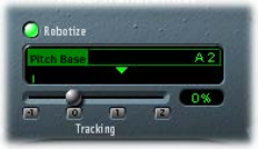
Chapter 11 Pitch eects 228
Use Vocal Transformer’s Robotize mode
1 Click the Robotize button to turn on Robotize mode. In this mode, Vocal Transformer can
augment or diminish the melody.
You can control the intensity of this distortion with the Tracking parameter.
2 Click one of the following buttons to immediately set the Tracking slider to one of these most
useful values:
•−1 button: Sets the slider to −100%. All intervals are mirrored.
•0 button: Sets the slider to 0%. Delivers interesting results, with every syllable of the vocal track
being sung at the same pitch. Low values turn sung lines into spoken language.
•1 button: Sets the slider to 100%. The range of the melody is maintained. Higher values
augment, and lower values diminish, the melody.
•2 button: Sets the slider to 200%. The intervals are doubled.
The Pitch Base parameter is used to transpose the note that the Tracking parameter is following.
For example, with Tracking set to 0%, the pitch of the (spoken) note is transposed to the chosen
base pitch value.
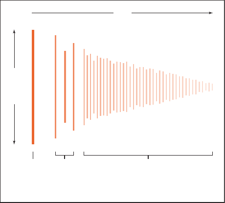
229
Reverb eects overview
You can use reverb eects to simulate the sound of acoustic environments such as rooms,
concert halls, caverns, or an open space.
Sound waves repeatedly bounce o the surfaces—walls, ceilings, windows, and so on—of any
space, or o objects within a space, gradually dying out until they are inaudible. These bouncing
sound waves result in a reection pattern, more commonly known as a reverberation (or reverb).
The starting portion of a reverberation signal consists of a number of discrete reections
that you can clearly discern before the diuse reverb tail builds up. These early reections are
essential in human perception of spatial characteristics, such as the size and shape of a room.
Signal Discrete
reflections
Diffuse reverb tail
Time
Reflection pattern/ reverberation
Amplitude
Plates, digital reverb eects, and convolution reverb
The rst form of reverb used in music production was actually a purpose-built room with hard
surfaces, called an echo chamber. It was used to add echoes to the signal. Mechanical devices,
including metal plates and springs, were also used to add reverberation to the output of musical
instruments and microphones.
Digital recording introduced digital reverb eects, which consist of thousands of delays of
varying lengths and intensities. The time dierences between the original signal and the arrival
of the early reections can be adjusted by a parameter commonly known as predelay. The
average number of reections in a given period of time is determined by the density parameter.
The regularity or irregularity of the density is controlled with the diusion parameter.
Today’s computers make it possible to sample the reverb characteristics of real spaces,
using convolution reverbs. These room characteristic sample recordings are known as
impulse responses.
Reverb eects 12
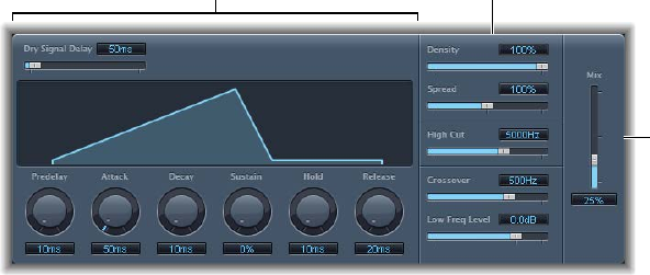
Chapter 12 Reverb eects 230
Convolution reverbs work by convolving (combining) an audio signal with the impulse response
recording of a room’s reverb characteristics. See Space Designer overview on page 238.
EnVerb
EnVerb overview
EnVerb is a versatile reverb eect with a unique feature: it allows you to adjust the envelope—
the shape—of the diuse reverb tail.
Mix
Time parameters Sound parameters
EnVerb is divided into three areas:
•Time parameters: These determine the delay time of the original signal and reverb tail, and
they change the reverb tail over time. The graphic display visually represents the levels over
time (the envelope) of the reverb. See EnVerb time parameters on page 231.
•Sound parameters: This area allows you to shape the sound of the reverb signal. You can also
split the incoming signal into two bands—with the Crossover parameter—and set the level of
the low frequency band separately. See EnVerb sound parameters on page 232.
•Mix slider: Drag to determine the balance between the eect (wet) and direct (dry) signals.
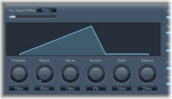
Chapter 12 Reverb eects 231
EnVerb time parameters
EnVerb provides the following time parameters.
EnVerb time parameters
•Dry Signal Delay slider and eld: Drag to determine the delay of the original signal. You can hear
the dry signal only when the Mix parameter is set to a value other than 100%.
•Graphic display: Shows changes to the reverb shape when knobs below the display
are adjusted.
•Predelay knob and eld: Rotate to set the time between the original signal and the start point
of the reverb attack phase—the very beginning of the rst reection.
•Attack knob and eld: Rotate to set the time it takes for the reverb to climb to its peak level.
•Decay knob and eld: Rotate to set the time it takes for the level of the reverb to drop from its
peak to the sustain level.
•Sustain knob and eld: Rotate to set the level of the reverb that remains constant throughout
the sustain phase. It is expressed as a percentage of the full-scale volume of the reverb signal.
•Hold knob and eld: Rotate to set the duration of the reverb sustain phase.
•Release knob and eld: Rotate to set the time it takes for the reverb to fade out completely,
after the sustain phase.
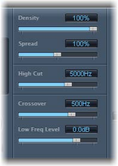
Chapter 12 Reverb eects 232
EnVerb sound parameters
EnVerb provides the following sound parameters that change the tonal color of the reverb eect.
EnVerb sound parameters
•Density slider and eld: Drag to set the reverb density.
•Spread slider and eld: Drag to control the width of the reverb’s stereo image. At 0% the eect
generates a monaural reverb. At 200% the stereo base is articially expanded.
•High Cut slider and eld: Drag to lter frequencies above the set value out of the reverb tail.
•Crossover slider and eld: Drag to set the frequency used to split the input signal into two
frequency bands for independent processing.
•Low Freq Level slider and eld: Drag to set the relative level of (reverb signal) frequencies below
the crossover frequency. In most cases you get better-sounding results when you set negative
values for this parameter.
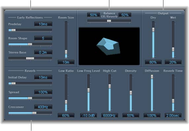
Chapter 12 Reverb eects 233
PlatinumVerb
PlatinumVerb overview
PlatinumVerb allows you to edit both the early reections and diuse reverb tail separately,
making it easy to precisely emulate real rooms. PlatinumVerb splits the incoming signal into two
bands: each is processed and can be edited separately.
Balance
ER/Reverb slider
Early Reflections
parameters
Output
parameters
Reverb parameters
PlatinumVerb is divided into four parameter areas:
•Early reections parameters: Emulate the original signal’s rst reections as they bounce o the
walls, ceiling, and oor of a natural room. See PlatinumVerb early reections parameters on
page 234.
•Reverb parameters: Control the diuse reverberations. See PlatinumVerb reverb parameters on
page 235.
•Output parameters: Determine the balance between the eected (wet) and direct (dry) signals.
See PlatinumVerb output parameters on page 236.
•Balance ER/Reverb slider: Drag to control the balance between the early reections and reverb
signal. When the slider is set to either extreme position, the other signal is not heard.
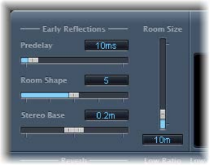
Chapter 12 Reverb eects 234
PlatinumVerb early reections parameters
PlatinumVerb provides the following early reections parameters.
PlatinumVerb early reections parameters
•Predelay slider and eld: Drag to set the time between the start of the original signal and the
arrival of the early reections.
•Extremely short: Predelay setting can color the sound and make it dicult to pinpoint the
position of the signal source.
•Very long: Predelay setting can be perceived as an unnatural echo and can divorce the
original signal from its early reections, leaving an audible gap between them.
•The optimum: Predelay setting depends on the type of input signal—or more precisely, the
envelope of the input signal. Percussive signals generally require shorter predelays than
signals where the attack fades in gradually. A good working method is to use the longest
possible Predelay value before you start to hear side eects, such as an audible echo. When
you reach this point, reduce the Predelay setting slightly.
•Room Shape slider and eld: Drag to dene the geometric form (the shape) of the room. The
numeric value (3 to 7) represents the number of corners in the room.
•Room Size slider and eld: Drag to determine the dimensions of the room. The numeric value
indicates the length of the room’s walls—the distance between two corners.
•Graphic display: Shows changes to Room Size and Room Shape parameters.
•Stereo Base slider and eld: Drag to set the distance between the two virtual microphones that
capture the simulated room signal.
Note: Spacing the microphones slightly farther apart than the distance between two human
ears generally delivers the best, and most realistic, results. This parameter is available only in
stereo instances of the eect.
•ER Scale slider and eld (Extended Parameters area): Drag to scale early reections along
the time axis. This slider inuences the Room Shape, Room Size, and Stereo Base
parameters simultaneously.
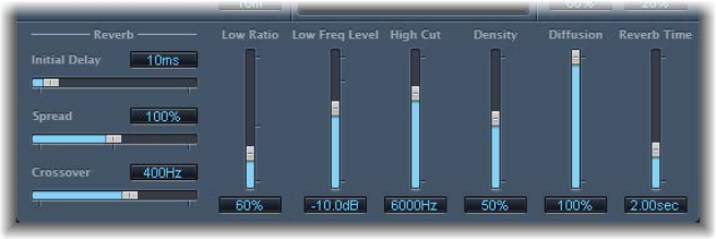
Chapter 12 Reverb eects 235
PlatinumVerb reverb parameters
PlatinumVerb provides the following reverb parameters.
PlatinumVerb reverb parameters
•Initial Delay slider and eld: Drag to set the time between the original signal and the diuse
reverb tail.
•Spread slider and eld: Drag to control the width of the reverb’s stereo image. At 0%, the eect
generates a monaural reverb. At 200%, the stereo base is articially expanded.
•Crossover slider and eld: Drag to set the frequency used to split the input signal into two
frequency bands, for separate processing.
•Low Ratio slider and eld: Drag to determine the relative reverb times of the bass and high
frequency bands. It is expressed as a percentage. At 100%, the reverb time of the two bands is
identical. At values below 100%, the reverb time of frequencies below the crossover frequency
is shorter. At values greater than 100%, the reverb time for low frequencies is longer.
•Low Freq Level slider and eld: Drag to set the level of the low frequency reverb signal. At 0 dB,
the volume of the two bands is equal. In most mixes, you should set a lower level for the
low frequency reverb signal. This enables you to boost the bass level of the incoming signal,
making it sound punchier. This also helps to counteract bottom-end masking eects.
•High Cut slider and eld: Drag to lter frequencies above the set value from the reverb signal.
Uneven or absorbent surfaces—wallpaper, wood paneling, carpets, and so on, tend to reect
lower frequencies better than higher frequencies. The High Cut lter replicates this eect. If
you set the High Cut lter so that it is wide open (maximum value), the reverb sounds as if it is
reecting o stone or glass.
•Density slider and eld: Drag to set the density of the diuse reverb tail. Ordinarily you want
the signal to be as dense as possible. In rare instances, however, a high Density value can color
the sound, which you can x by reducing the Density slider value. Conversely, if you select a
Density value that is too low, the reverb tail sounds grainy.
•Diusion slider and eld: Drag to set the diusion of the reverb tail. High Diusion values
represent a regular density, with few alterations in level, times, and panorama position over
the course of the diuse reverb signal. Low Diusion values result in the reection density
becoming irregular and grainy. This also aects the stereo spectrum. As with Density, nd the
best balance for the signal.
•Reverb Time slider and eld: Drag to determine the reverb time of the high frequency band.
Most natural rooms have a reverb time somewhere in the range of 1 to 3 seconds. This time is
reduced by absorbent surfaces, such as carpet and curtains, and soft or dense furnishings, such
as sofas, armchairs, cupboards, and tables. Large empty halls or churches have reverb times of
up to 8 seconds, with some cavernous or cathedral-like venues extending beyond that.
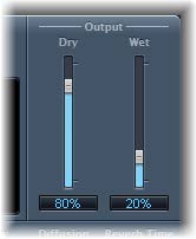
Chapter 12 Reverb eects 236
PlatinumVerb output parameters
PlatinumVerb provides the following output parameters.
PlatinumVerb output parameters
•Dry slider and eld: Drag to control the amount of the original signal.
•Wet slider and eld: Drag to control the amount of the eect signal.
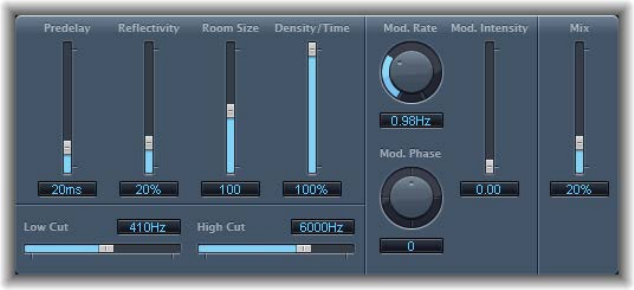
Chapter 12 Reverb eects 237
SilverVerb
SilverVerb provides a low frequency oscillator (LFO) that can modulate the reverberated signal.
It also includes a high cut and a low cut lter, allowing you to lter frequencies from the reverb
signal. High frequency transients in reverb signals can sound unpleasant, can hamper speech
intelligibility, or mask the overtones of the original signal. Long reverb tails with a lot of bass
generally result in an indistinct mix.
SilverVerb parameters
•Predelay slider and eld: Drag to set the time between the original signal and the reverb signal.
•Reectivity slider and eld: Drag to dene how reective the imaginary walls, ceiling, and
oor are.
•Room Size slider and eld: Drag to dene the dimensions of the simulated room.
•Density/Time slider and eld: Drag to determine both the density and the duration of
the reverb.
•Low Cut slider and eld: Drag to lter frequencies below the set value out of the reverb signal.
This aects only the tone of the reverb signal, not the original signal.
•High Cut slider and eld: Drag to lter frequencies above the set value out of the reverb signal.
This aects only the tone of the reverb signal, not the original signal.
•Mod(ulation) Rate knob and eld: Drag to set the frequency (the speed) of the LFO.
•Mod(ulation) Phase knob and eld: Drag to dene the phase of the modulation between the
left and right channels of the reverb signal.
•At 0°, the extreme values (minimum or maximum) of the modulation are achieved
simultaneously on both the left and right channels.
•At a value of 180°, the extreme values opposite each other (left channel minimum, right
channel maximum, or vice versa) are reached simultaneously.
•Mod(ulation) Intensity slider and eld: Drag to set the modulation amount. A value of 0 turns o
the delay modulation.
•Mix slider and eld: Drag to set the balance between the eect (wet) and original (dry) signals.
238
Space Designer overview
Space Designer is a convolution reverb eect that you can use to place your audio signals in
exceptionally realistic recreations of real-world acoustic environments. Space Designer generates
reverb by convolving, or combining, an audio signal with an impulse response reverb sample. An
impulse response is a recording of a room’s reverb characteristics, or more precisely, a recording
of all reections in a given room following an initial signal spike. The actual impulse response le
is a standard audio le.
To understand how this works, imagine a situation where Space Designer is used on a vocal
track. An impulse response le recorded in an actual opera house is loaded into Space Designer.
This impulse response le is convolved with your vocal track, placing the singer inside the opera
house.
Convolution can be used to place your audio signal inside any space, including a speaker cabinet,
a plastic toy, a cardboard box, and so on. All you need is an impulse response recording of
the space.
In addition to loading impulse responses, Space Designer includes an on-board impulse response
synthesis facility. This enables you to create completely unique eects, particularly when the
synthesized impulse response doesn’t represent a real space.
Space Designer also oers features such as envelopes, lters, EQ, and stereo/surround
balance controls, which provide precise control over the dynamics, timbre, and length of
the reverberation.
Space Designer can operate as a mono, stereo, true stereo (meaning each channel is processed
discretely), or surround eect.
Automation and Space Designer
Space Designer cannot be fully automated—unlike most other Logic Pro plug-ins. This is because
Space Designer needs to reload the impulse response and recalculate the convolution before
audio can be routed through it.
You can, however, record, edit, and play back any movement of the following Space Designer
parameters in a suitable host application:
•Stereo Crossfeed
•Direct Output
•Reverb Output
Space Designer convolution reverb 13
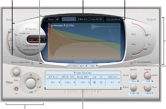
Chapter 13 Space Designer convolution reverb 239
Space Designer interface
The Space Designer interface consists of the following main sections:
Global
parameters
Filter parameters
Main display
Global
parameters
Button bar
Impulse
response
parameters
Parameter bar
Envelope and
EQ parameters
•Impulse response parameters: Use to load, save, or manipulate recorded or synthesized impulse
response les. The chosen impulse response le determines what Space Designer will use to
convolve with your audio signal. See Use impulse responses on page 240.
•Envelope and EQ parameters: Use the view buttons in the button bar to switch the main
display and parameter bar between envelope and EQ views. Use the main display to edit the
displayed parameters graphically, and use the parameter bar to edit them numerically. See
Space Designer envelopes and EQ overview on page 243.
•Filter parameters: Use to modify the timbre of the Space Designer reverb. You can choose from
several lter modes, adjust resonance, and also adjust the lter envelope dynamically over
time. See Space Designer lter parameters on page 250.
•Global parameters: After your impulse response is loaded, use these parameters to determine
how Space Designer operates on the overall signal and impulse response. Included are
input and output parameters, delay and volume compensation, predelay, and so on. See
Space Designer global parameters overview on page 252.
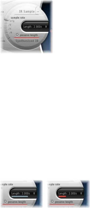
Chapter 13 Space Designer convolution reverb 240
Use impulse responses
Space Designer can use either recorded impulse response les or synthesized impulse responses.
The circular area to the left of the main display contains the impulse response parameters. These
are used to determine the impulse response mode (IR Sample mode or Synthesized IR mode), to
load or create impulse responses, and to set the sample rate and length.
Impulse response parameters
•IR Sample button and pop-up menu: Click the IR Sample button to switch to IR Sample mode.
In IR Sample mode, an impulse response sample is used to generate reverberation. Click the
down arrow next to the IR Sample button to open the IR Sample pop-up menu.
•Synthesized IR button: Click to turn on Synthesized IR mode. A new synthesized impulse
response is generated, which is derived from the values of the Length, envelope, Filter, EQ, and
Spread parameters.
•Sample rate slider: Move to determine the sample rate of the loaded impulse response.
•Preserve length button: Click to preserve the original length of the impulse response when
changing the sample rate with the sample rate slider.
•Length eld: Move to adjust the length of the impulse response.
Important: To convolve audio in real time, Space Designer must rst calculate any parameter
adjustments to the impulse response. This requires a moment or two following parameter edits
and is indicated by a blue progress bar. During this parameter edit processing time you can
continue to adjust the parameter. When calculation starts, the blue bar is replaced by a red bar,
indicating that a calculation is occurring.
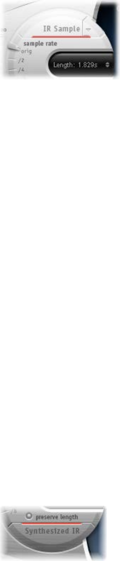
Chapter 13 Space Designer convolution reverb 241
Turn on IR Sample mode
In IR Sample mode, Space Designer loads and uses an impulse response recording of an acoustic
environment. This is convolved with the incoming audio signal to place it in the acoustic space
provided by the impulse response.
1 Click the IR Sample button in the circular area to the left of the main display.
2 Select an impulse response le from any folder.
Note: If you have already loaded an impulse response le, clicking the IR Sample button switches
the mode from Synthesized IR to IR Sample mode.
Manage the loaded impulse response le
mClick the down arrow next to the IR Sample button to open a pop-up menu containing the
following commands:
•Load IR: Loads an impulse response sample without changing the envelopes.
•Load IR & Init: Loads an impulse response sample and initializes the envelopes.
•Show in Finder: Opens a Finder window that shows the location of the currently loaded
impulse response le.
All impulse responses that ship with Logic Pro are installed in the /Library/Audio/Impulse
Responses/Apple folder. Deconvolution les have an .sdir le extension.
Any mono, stereo, AIFF, SDII, or WAV le can be used as an impulse response. In addition,
surround formats up to 7.1, discreet audio les, and B-format audio les that consist of a single
surround impulse response can also be used.
Use Synthesized IR mode
In Synthesized IR mode, Space Designer generates a synthesized impulse response based on the
values of the Length, envelope, Filter, EQ, and Spread parameters.
Note: You can switch between a loaded impulse response sample and a synthesized impulse
response without losing the settings of the other.
mClick the Synthesized IR button in the Impulse Response Parameters section.
Repeated clicks of the active Synthesized IR button will randomly generate new impulse
responses with slightly dierent reection patterns. The current impulse response state
(including parameter and other values that represent the reection patterns and characteristics
of the synthetic impulse response) is saved with the setting le.
Note: Clicking the Synthesized IR button while you are in IR Sample mode switches you back to
the synthesized impulse response stored with the setting.
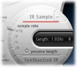
Chapter 13 Space Designer convolution reverb 242
Set the impulse response sample rate and preserve length
Changing the sample rate upward increases—or changing it downward decreases—the
frequency response (and length) of the impulse response, and to a degree the overall sound
quality of the reverb. Upward sample rate changes are of benet only if the original impulse
response sample actually contains higher frequencies. When reducing the sample rate, use your
ears to decide if the sonic quality meets your needs.
Note: Natural room surfaces—except concrete and tiles—tend to have minimal reections
in the higher frequency ranges, making the half-rate and full-rate impulse responses sound
almost identical.
mTo determine the sample rate of an impulse response: Move the sample rate slider.
•Orig: Space Designer uses the current project sample rate. When loading an impulse response,
Space Designer automatically converts the sample rate of the impulse response to match
the current project sample rate, if necessary. For example, this allows you to load a 44.1 kHz
impulse response into a project running at 96 kHz, and vice versa.
•/2, /4, /8: These settings are half-divisions of the preceding value—one-half, one-quarter, one-
eighth. For example:
•If the project sample rate is 96 kHz, the options are 48 kHz, 24 kHz, and 12 kHz.
•If the project sample rate is 44.1 kHz, the options are 22.05 kHz, 11.025 kHz, and 5512.5 Hz.
When you select half the sample rate, the impulse response becomes twice as long. The
highest frequency that can be reverberated is halved. This results in a behavior that is much
like doubling every dimension of a virtual room—multiplying a room’s volume by eight. The
lower sample rates can also be used for interesting tempo, pitch, and retro digital sounding
eects. Another benet of reducing the sample rate is that processing requirements drop
signicantly, making half–sample rate settings useful for large, open spaces.
mTo retain the original length of the impulse response when the sample rate is changed: Click the
preserve length button. Manipulating this parameter in conjunction with the sample rate
parameter can lead to interesting results.
If you are running Space Designer in a project that uses a higher sample rate than the impulse
response, you may also want to reduce the impulse response sample rate. Make sure the
preserve length button is turned on. This cuts CPU processing time without compromising
reverb quality.
Tip: You can make similar adjustments while running in Synthesized IR mode. Most typical
reverb sounds don’t have an excessive amount of high frequency content. If your project is
running at 96 kHz, for example, you would need to use lowpass ltering to obtain the mellow
frequency response characteristics of many reverb sounds. A better approach would be to rst
reduce the high frequencies by 1/2 or even 1/4 using the “sample rate” slider, followed by using
the lowpass lter, thus conserving signicant CPU resources.
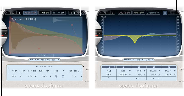
Chapter 13 Space Designer convolution reverb 243
Set impulse response lengths
mMove the Length parameter to set the length of the impulse response—sampled or synthesized.
All envelopes are automatically calculated as a percentage of the overall length, which means
that if this parameter is altered, your envelope curves will stretch or shrink to t.
Note: When you are using an impulse response le, the Length parameter value cannot exceed
the length of the actual impulse response sample. Longer impulse responses (sampled or
synthesized) place a higher strain on the CPU.
Space Designer envelopes and EQ
Space Designer envelopes and EQ overview
Space Designer’s main interface area is used to show and edit envelope and equalizer
(EQ) parameters. It consists of the button bar at the top, the main display, and the parameter bar.
•The button bar is used to choose the current view/edit mode.
•The main display shows, and allows you to graphically edit, either the envelope or the
EQ curve.
•The parameter bar displays, and allows you to numerically edit, either the envelope or the
EQ curve.
Main display Parameter bar
Display in
Envelope view Display in EQ view
Button bar

Chapter 13 Space Designer convolution reverb 244
Space Designer button bar
The button bar is used to switch the main display and parameter bar between envelope
and EQ views. It also includes buttons that reset the envelopes and EQ or reverse the
impulse response.
Button bar parameters
•Reset button: Click to reset the currently displayed envelope or EQ to default values.
•All button: Click to reset all envelopes and the EQ to default values.
•Volume Env button: Click to show the volume envelope in the foreground of the main
display. The other envelope curves are shown as transparencies in the background. See
Space Designer volume envelope on page 246.
•Filter Env button: Click to show the lter envelope in the foreground of the main display. The
other envelope curves are shown as transparencies in the background. See Space Designer
lter parameters on page 250.
•Density Env button: Click to show the density envelope in the foreground of the main display.
The other envelope curves are shown as transparencies in the background. See Use impulse
responses on page 240.
•EQ button: Click to show the four-band parametric EQ in the main display. See Use
Space Designer EQ parameters on page 248.
•Reverse button: Click to reverse the impulse response and envelopes. When the impulse
response is reversed, you are eectively using the tail rather than the front end of the sample.
You may need to change the Pre-Dly and other parameter values when reversing.
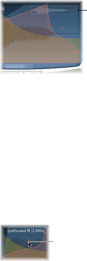
Chapter 13 Space Designer convolution reverb 245
Edit Space Designer envelope parameters
You can edit the volume and lter envelopes of all impulse responses and the density envelope
of synthesized impulse responses. All envelopes can be adjusted both graphically in the main
display as well as numerically in the parameter bar.
Whereas some parameters are envelope-specic, all envelopes consist of the Attack Time and
Decay Time parameters. The combined total of the Attack Time and Decay Time parameters is
equal to the total length of the synthesized or sampled impulse response, unless the Decay time
is reduced. See Use impulse responses on page 240.
The large nodes are value indicators of the parameters shown in the parameter bar below the
main display—Init Level, Attack Time, Decay Time, and so on. If you edit any numerical value in
the parameter bar, the corresponding node moves in the main display.
When displaying envelopes, the main display oers the following zoom and navigation
parameters (not shown in EQ view).
Overview display
Envelope navigation parameters
•Overview display: Indicates which portion of the impulse response le is currently visible in the
main display, helping you to orient yourself when zooming.
•Zoom to Fit button: Click to display the entire impulse response waveform in the main display.
Any envelope length changes are automatically reected.
•A and D buttons: Click to limit the Zoom to Fit function to the attack and decay portions of the
currently selected envelope shown in the main display. The A and D buttons are available only
when you are viewing the volume and lter envelopes.
Move an envelope node graphically in Space Designer
mDrag the node in one of the available directions.
Two arrows are shown when you move the pointer over any node in the main display, indicating
possible movements.
Change Space Designer’s envelope curve shape graphically
1 Drag the envelope curve in the main display.
2 Drag the small nodes attached to a line for ne adjustments to envelope curves. These nodes are
tied to the envelope curve itself, so you can view them as envelope handles.
Move the nodes vertically
or horizontally to change the
shape of the envelope curve.
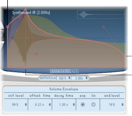
Chapter 13 Space Designer convolution reverb 246
Space Designer volume envelope
The volume envelope is used to set the reverb’s initial level and adjust how the volume will
change over time. You can edit all volume envelope parameters numerically, and you can also
edit many of them graphically (see Edit Space Designer envelope parameters on page 245).
Attack/Decay
Time node
Init Level node
Decay Time/End
Level node
Volume envelope parameters
•Init Level eld: Sets the initial volume level of the impulse response attack phase. It is
expressed as a percentage of the full-scale volume of the impulse response le. The attack
phase is generally the loudest point of the impulse response. Set Init Level to 100% to ensure
maximum volume for the early reections.
•Attack Time eld: Determines the time before the decay phase of the volume envelope begins.
•Decay Time eld: Sets the length of the decay phase.
•Volume decay mode buttons: Set the volume decay curve type.
•Exp: The output of the volume envelope is shaped by an exponential algorithm, to generate
the most natural-sounding reverb tail.
•Lin: The volume decay will be more linear, and less natural sounding.
•End Level eld: Sets the end volume level. It is expressed as a percentage of the overall volume
envelope.
•If set to 0%, you can fade out the tail.
•If set to 100%, you can’t fade out the tail, and the reverb stops abruptly if the end point falls
within the tail. (If the end time falls outside the reverb tail, End Level has no eect.)
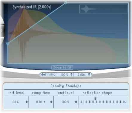
Chapter 13 Space Designer convolution reverb 247
Space Designer density envelope
The density envelope allows you to control the density of the synthesized impulse response
over time. You can adjust the density envelope numerically in the parameter bar, and you can
edit the Init Level, Ramp Time, and End Level parameters using the techniques described in Edit
Space Designer envelope parameters on page 245.
Note: The density envelope is available only in Synthesized IR mode.
Density envelope parameters
•Init Level eld: Sets the initial density (the average number of reections in a given period of
time) of the reverb. Lowering the density levels results in audible reections patterns and
discreet echoes.
•Ramp Time eld: Adjusts the time between the Initial and End Density levels.
•End Level eld: Sets the density of the reverb tail. If you select an End Level value that is too
low, the reverb tail sounds grainy. The stereo spectrum might also be aected by lower values.
•Reection Shape slider: Determines the steepness (shape) of early reection clusters as they
bounce o the walls, ceiling, and furnishings of the virtual space. Small values result in clusters
with a sharp contour, and large values result in an exponential slope and a smoother sound.
This is handy when recreating rooms constructed of dierent materials. Reection Shape, in
conjunction with suitable settings for the envelopes, density, and early reection, will assist
you in creating rooms of almost any shape and material.
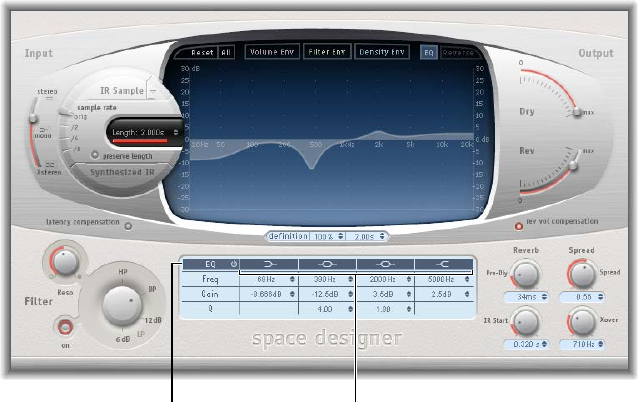
Chapter 13 Space Designer convolution reverb 248
Use Space Designer EQ parameters
Space Designer has a four-band EQ consisting of two parametric mid-bands plus two shelving
lters (one low shelving lter and one high shelving lter). You can edit the EQ parameters
numerically in the parameter bar or graphically in the main display.
EQ On/Off button Individual EQ band buttons
•EQ On/O button: Click to turn the entire EQ section on or o.
•EQ band buttons: Click to turn individual EQ bands on or o.
•Frequency elds: Set the frequency for the selected EQ band.
•Gain elds: Cut or boost the selected EQ band.
•Q elds: Set the Q factor for the two parametric bands. The Q factor can be adjusted from 0.1
(very narrow) to 10 (very wide).
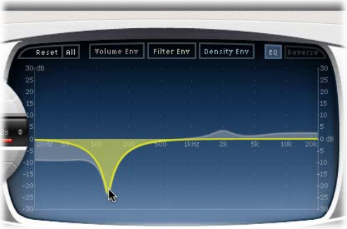
Chapter 13 Space Designer convolution reverb 249
Graphically edit an EQ curve in Space Designer
1 Enable the EQ and one or more bands with the EQ On/O and EQ band buttons in the top row
of the parameter bar.
2 Move the cursor horizontally over the main display. When the cursor is in the access area of a
band, the corresponding curve and parameter area are automatically highlighted and a pivot
point is displayed.
3 Drag horizontally to adjust the frequency of the band.
4 Drag vertically to increase or decrease the Gain of the band.
5 Vertically drag the highlighted pivot point of a parametric EQ band to raise or lower the Q value.
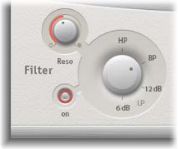
Chapter 13 Space Designer convolution reverb 250
Space Designer lter
Space Designer lter parameters
Space Designer’s lter provides control over the timbre of the reverb.
You can select from several lter types and also have envelope control over the lter cuto,
which is independent of the volume envelope. Changes to lter settings result in a recalculation
of the impulse response rather than a straight change to the sound as it plays through
the reverb.
The main lter parameters are located in the lower-left corner of the interface.
Main lter parameters
•Filter On button: Click to switch the lter section on or o.
•Filter mode knob: Rotate to set the lter mode.
•6 dB (LP): Bright, general-purpose lowpass lter mode that retains the top end of most
material while still providing some ltering.
•12 dB (LP): Warm, lowpass lter mode without drastic lter eects that smooths out
bright reverbs.
•BP: 6 dB per octave bandpass design that reduces the low and high ends of the signal,
leaving the frequencies around the cuto frequency intact.
•HP: 12 dB per octave/two-pole highpass design that reduces the level of frequencies that fall
below the cuto frequency.
•Reso(nance) knob: Rotate to emphasize frequencies above, around, or below the cuto
frequency. The impact of the resonance knob on the sound is highly dependent on the chosen
lter mode, with steeper lter modes resulting in more pronounced tonal changes.
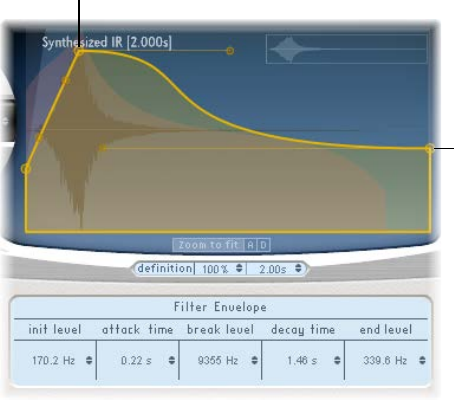
Chapter 13 Space Designer convolution reverb 2 51
Space Designer lter envelope
The lter envelope appears in the main display when you click the Filter Env button. You can use
it to control the lter cuto frequency over time. You can adjust all lter envelope parameters
either numerically in the parameter bar or graphically in the main display using the techniques
discussed in Edit Space Designer envelope parameters on page 245.
Note: Activation of the lter envelope automatically enables the main lter.
Controls the Decay endpoint
and End Level parameters
simultaneously.
Controls the Attack Time endpoint
(and Decay Time startpoint)
and Break Level parameters
simultaneously.
Filter envelope parameters
•Init Level eld: Sets the initial cuto frequency of the lter envelope.
•Attack Time eld: Determines the time required to reach the Break Level.
•Break Level eld: Sets the maximum lter cuto frequency that the envelope reaches. This
setting also acts as the separation point between the attack and decay phases of the overall
lter envelope. In other words, when the selected level has been reached after the attack
phase, the decay phase begins. You can create interesting lter sweeps by setting the Break
Level to a value lower than the Init Level.
•Decay Time eld: Determines the time required after the Break Level point to reach the End
Level value.
•End Level eld: Sets the cuto frequency at the end of the lter envelope decay phase.
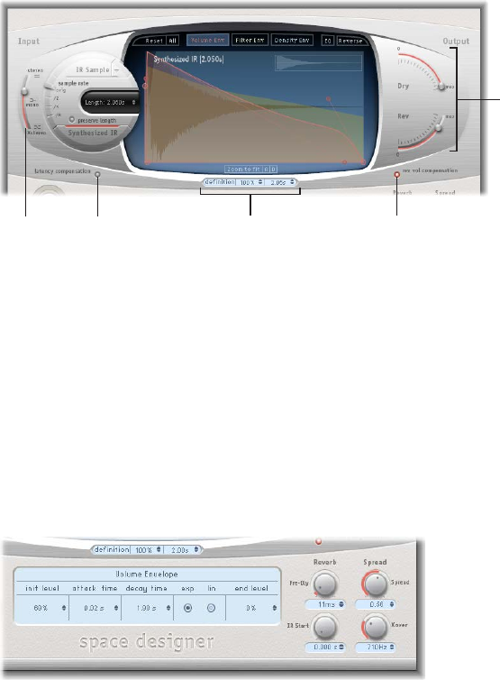
Chapter 13 Space Designer convolution reverb 252
Space Designer global parameters
Space Designer global parameters overview
Space Designer’s global parameters aect the overall output or behavior of the eect. See Use
Space Designer global parameters and Use Space Designer output parameters.
The global parameters are divided into two sections—those around the main display and those
below the main display.
Latency
Compensation button
Rev Vol
Compensation button
Output
sliders
Definition
area
Input
slider
Global parameters (upper)
•Input slider: Move to determine how Space Designer processes a stereo or surround
input signal.
•Latency Compensation button: Click to switch Space Designer’s internal latency compensation
feature on or o.
•Denition elds: Drag to select a less-dened impulse response set, to emulate reverb diusion
and save CPU resources.
•Rev(erb) Vol(ume) Compensation button: Click to turn on Space Designer’s internal impulse
response volume matching function.
•Output sliders: Move to adjust output levels.
Global parameters (lower)
•Pre-Dly knob and eld: Rotate to set the reverb’s predelay time, or time between the original
signal and the rst reections from the reverb.
•IR Start knob and eld: Rotate to set the playback start point in the impulse response sample.
•Spread and Xover knobs and elds: Rotate the Spread knob to adjust the perceived width of
the stereo or surround eld, and rotate the Xover knob to set the crossover frequency. Any
synthesized impulse response frequency that falls below this value is aected by the Spread
parameter. (These knobs are available only for synthesized impulse responses.)
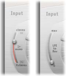
Chapter 13 Space Designer convolution reverb 253
Use Space Designer global parameters
Space Designer’s global parameters aect the overall output or behavior of the eect. See
Space Designer global parameters overview.
The tasks below cover the use of Space Designer’s global parameters.
Use the Space Designer Input slider
The Input slider behaves dierently in stereo or surround congurations. (The slider does not
appear in mono or mono to stereo instances of the eect.)
Stereo Surround
mIn stereo instances: Drag the Input slider to determine how a stereo signal is processed.
•Stereo setting (top of slider): The signal is processed on both channels, retaining the stereo
balance of the original signal.
•Mono setting (middle of slider): The signal is processed in mono.
•XStereo setting (bottom of slider): The signal is inverted, with processing for the right channel
occurring on the left, and vice versa.
•In-between positions: A mixture of stereo to mono crossfeed signals is produced.
mIn surround instances: Drag the Input slider to determine how much LFE signal is mixed with the
surround channels routed into the reverb.
•Surround Max setting (top of slider): The maximum amount of Low Frequency Eects
(LFE) signal is mixed with the other surround channels.
•Surround 0 setting (bottom of slider): The entire LFE signal is passed through the reverb
unprocessed.
•In-between positions: A mixture of LFE and surround channel information is processed.
Use Space Designer’s latency compensation feature
The complex calculations made by Space Designer take a small amount of time, which results in
a processing delay, or latency, between the direct input signal and the processed output signal.
Note: This compensation feature is not related to latency compensation in the host application;
it occurs entirely within Space Designer.

Chapter 13 Space Designer convolution reverb 254
mClick the Latency Compensation button to turn it on, which delays the direct signal in the Output
section so that it matches the processing delay of the eect signal.
Space Designer’s processing latency is 128 samples at the original sample rate, and it doubles at
each lower sample rate division. The processing latency increases to 256 samples if you set Space
Designer’s sample rate slider to “/2.” Processing latency does not increase in surround mode or at
sample rates above 44.1 kHz.
Use Space Designer’s Denition parameter
The Denition parameter emulates the diusion of natural reverb patterns. When used at values
of less than 100% it also reduces CPU processing requirements.
Natural reverbs contain most of their spatial information in the rst few milliseconds. Toward
the end of the reverb, the pattern of reections—signals bouncing o walls, and so on—
becomes more diuse. In other words, the reected signals become quieter and increasingly
nondirectional, containing far less spatial information. To emulate this phenomenon, use the
full impulse response resolution only at the onset of the reverb, then use a reduced impulse
response resolution toward the end of the reverb.
mDrag either of the Denition elds vertically to set the crossover point—where the switch to the
reduced impulse response resolution occurs.
The rst Denition eld is shown as a percentage, where 100% is equal to the length of the full
resolution impulse response. The second eld is shown in milliseconds, which indicate the exact
crossover point position. (These two elds are linked, so making a change in one automatically
changes the other.)
Note: The Denition elds are visible below the main display only when you have loaded CPU-
intensive synthesized impulse responses.
Use Space Designer’s reverb volume compensation feature
The reverb volume compensation feature attempts to match the perceived—not the actual—
volume dierences between impulse response les. The rev vol compensation button is turned
on by default and should generally be left in this mode, although it may not work with all types
of impulse responses.
mIf you have an impulse response that is of a dierent level, turn o reverb volume compensation
and adjust input and output levels accordingly.
Chapter 13 Space Designer convolution reverb 255
Use Space Designer’s predelay feature
Predelay is the amount of time that elapses between the original signal and the initial early
reections of the reverberation. For a room of any given size and shape, predelay is determined
by the distance between the listener and the walls, ceiling, and oor. Space Designer allows you
to adjust this parameter over a greater range than what would be considered natural.
mTo set a suitable predelay time, rotate the Pre-Dly knob.
The ideal predelay setting for dierent sounds depends on the properties of—or more
accurately, the envelope of—the original signal. Percussive signals generally require shorter
predelays than signals where the attack fades in gradually, such as strings. A good rule of thumb
is to use the longest predelay possible before undesirable side eects, such as an audible echo,
begin to materialize.
In practice, an extremely short predelay tends to make it dicult to pinpoint the position of the
signal source. It can also color the sound of the original signal. On the other hand, an excessively
long predelay can be perceived as an unnatural echo. It can also divorce the original signal from
its early reections, leaving an audible gap between the original and reverb signals.
These guidelines are intended to help you design realistic-sounding spaces that are suitable for
various signals. If you want to create unnatural sound stages or otherworldly reverbs and echoes,
experiment with the Pre-Dly parameter.
Change the impulse response start point
Using the IR Start parameter aords a number of other options that can be quite creative,
particularly when combined with the Reverse function. See Space Designer button bar on
page 244.
Note: The IR Start parameter is neither available nor necessary in Synthesized IR mode, because
the Length parameter provides identical functionality.
mRotate the IR Start knob to shift the playback start point of the impulse response.
This eectively cuts o the beginning of the impulse response, which can be useful for
eliminating level peaks at the start of the impulse response sample.

Chapter 13 Space Designer convolution reverb 256
Use Space Designer output parameters
Space Designer’s global parameters aect the overall output or behavior of the eect. See
Space Designer global parameters overview.
The tasks below cover the use of Space Designer’s output parameters.
Set Space Designer mono/stereo output parameters
Use the output parameters to adjust the balance between the direct, or dry, signals and
the processed signals. The parameters that are available depend on Space Designer’s input
conguration.
Space Designer provides two output sliders—the Dry slider for the direct signal, and the Rev
slider for the reverb signal—when you insert it as a mono, mono to stereo, or stereo eect.
Mono/Stereo Surround
mTo set the level of the Dry slider: Move to set the level of the non-eect, or dry, signal. Move the
slider to a value of 0 (mute) if Space Designer is inserted in a bus channel or you are using
modeling impulse responses, such as speaker simulations.
mTo set the level of the Rev(erb) slider: Move to adjust the output level of the eect, or wet, signal.
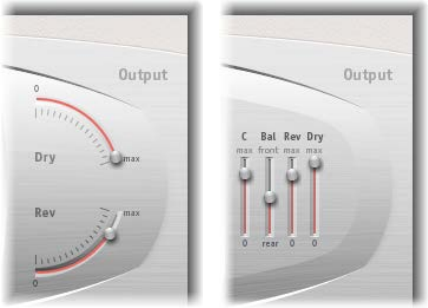
Chapter 13 Space Designer convolution reverb 257
Set Space Designer surround output parameters
Use the output parameters to adjust the balance between the direct, or dry, signal and the
processed signals. The parameters that are available depend on Space Designer’s input
conguration.
In surround congurations, Space Designer provides four output sliders that together comprise a
small surround output mixer.
Mono/Stereo Surround
mTo set the level of the C(enter) slider: Move to adjust the output level of the center channel
independently of other surround channels.
mTo set the level of the Bal(ance) slider: Move to set the level balance between the front (L-C-R) and
rear (Ls-Rs) channels.
•In 7.1 ITU surround, the balance pivots around the Lm-Rm speakers, taking the surround angles
into account.
•In 7.1 SDDS surround, the Lc-Rc speakers are considered front speakers.
mTo set the level of the Rev(erb) slider: Move to adjust the output level of the eect, or wet, signal for
all channels.
mTo set the level of the Dry slider: Move to set the overall level of the non-eect signal for all
channels. Move the slider to a value of 0 (mute) when you use Space Designer as a bus eect
in an aux channel strip. Use the Send knob of each bussed channel strip to control the wet/
dry balance.
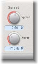
Chapter 13 Space Designer convolution reverb 258
Use the Space Designer Spread parameters
The Spread and Xover (crossover) knobs enhance the perceived width of the signal without
losing the directional information of the input signal normally found in the higher frequency
range. Low frequencies are spread to the sides, reducing the amount of low frequency content in
the center—allowing the reverb to encompass the mix.
Note: The Spread and Xover knobs function only in Synthesized IR mode.
mTo set the level of the Spread knob and eld: Rotate to extend the stereo or surround base to
frequencies that fall below the frequency determined by the Xover parameter.
•At a Spread value of 0.00, no stereo or surround information is added. (The inherent stereo or
surround information of the source signal and reverb, however, is retained.)
•At a Spread value of 1.00, the left and right channel divergence is at its maximum.
mTo set the level of the Xover knob and eld: Rotate to set the crossover frequency in Hertz. Any
synthesized impulse response frequency that falls below the value you set will be aected by the
Spread parameter (at values over 0).
Note: Because these parameters adjust stereo or surround processing, they have no impact
when you use Space Designer as a mono plug-in.
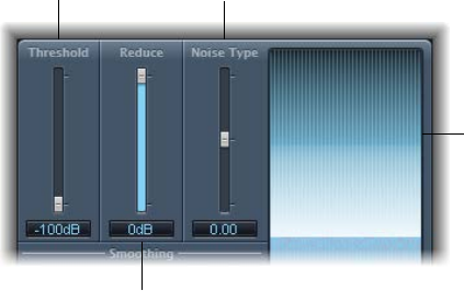
259
Specialized eects overview
Logic Pro includes a bundle of specialized eects and utilities designed to address tasks often
encountered during audio production:
•Denoiser eliminates or reduces noise below a threshold level.
•Exciter adds life to your recordings by generating articial high frequency components.
•Grooveshifter creates rhythmic variations in your recordings.
•Speech Enhancer improves speech recordings made with your computer’s
internal microphone.
•SubBass generates an articial bass signal that is derived from the incoming signal.
Denoiser
Denoiser overview
Denoiser eliminates or reduces any noise below a threshold volume level. It does this by using
Fast Fourier Transform (FFT) analysis to identify frequency bands of lower volume and less
complex harmonic structure, which it then reduces to the dened decibel level.
If you use Denoiser too aggressively, you may encounter artifacts that are less pleasant than
the existing noise. Use the three Smoothing knobs to reduce or eliminate these artifacts. See
Denoiser smoothing parameters.
Graphic display
Reduce slider and field
Threshold slider
and field
Noise Type slider
and field
Specialized eects and utilities 14
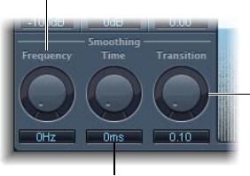
Chapter 14 Specialized eects and utilities 260
Denoiser main parameters
•Threshold slider and eld: Drag to set the threshold level below which the noise signals
are reduced.
Locate a section of the audio where only noise is audible, then set the Threshold slider to a dB
value that lters only signals at or below this level.
•Reduce slider and eld: Drag to set the amount of noise reduction applied to signals that fall
below the threshold. Aim for a Reduce slider value where noise reduction is optimal but little
of the music or vocal signal is reduced. Each 6 dB reduction halves the volume level, and each
6 dB increase doubles it.
Note: If the noise level of your recording is very high (more than −68 dB), reducing it to a level
of −83 to −78 dB should suce, provided no audible side eects are introduced. This reduces
the noise by more than 10 dB, to less than half its original volume.
•Noise Type slider and eld: Drag to determine the type of noise you want to reduce.
•A value of 0 equals white noise—equal frequency distribution.
•Positive values change the noise type to pink noise—harmonic noise; greater bass response.
•Negative values change the noise type to blue noise—hissy tape noise.
•Graphic display: Shows how the lowest volume level signals in your audio material, which are
mostly or entirely noise, are reduced.
Denoiser smoothing parameters
Denoiser has the following smoothing parameters:
Time knob and field
Frequency knob
and field
Transition knob
and field
Denoiser smoothing parameters
•Frequency knob and eld: Rotate to adjust how smoothing is applied to neighboring
frequencies. If Denoiser recognizes that only noise is present on a certain frequency band, use
the Frequency parameter to smooth the neighboring frequencies to avoid artifacts. The higher
you set the Frequency parameter, the more the neighboring frequency bands are changed.
•Time knob and eld: Rotate to set the time required to reach maximum noise reduction. This is
the simplest form of smoothing.
Note: The Time parameter also sets a release time, which is the time required for the signal
to revert to its normal level from the maximum noise reduction level. As with all Denoiser
parameters, the Threshold value determines the level that triggers the noise reduction process.
•Transition knob and eld: Rotate to adjust how smoothing is applied to neighboring volume
levels. If Denoiser recognizes that only noise is present in a certain volume range, use the
Transition parameter to smooth the neighboring volume levels to avoid artifacts. The higher
you set the Transition parameter, the more similar-level values are changed.
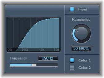
Chapter 14 Specialized eects and utilities 261
Exciter
Exciter generates high frequency components that are not part of the original signal. It does this
by utilizing a nonlinear distortion process that resembles the one used to produce overdrive and
distortion eects.
Unlike this process, however, Exciter’s distortion process involves passing the input signal
through a highpass lter before feeding it into the harmonics (distortion) generator. Articial
harmonics are thus added to the original signal, and these added harmonics contain frequencies
at least one octave above the threshold of the highpass lter. The distorted signal is then mixed
with the original, dry signal.
You can use Exciter to add life to recordings, particularly audio tracks with a weak treble
frequency range. You can also use Exciter to enhance guitar tracks.
Exciter parameters
•Frequency display: Shows the frequency range used as the source signal for the excite process.
•Frequency slider and eld: Drag to set the cuto frequency of the highpass lter, which is
expressed in Hertz. The input signal passes through the lter before (harmonic) distortion
is introduced.
•Input button: Turn on to mix the original (pre-eect) signal with the eect signal. If you turn o
input, only the eect signal is heard.
•Harmonics knob and eld: Rotate to set the ratio between the eect and the original signals,
which is expressed as a percentage. If the Input button is turned o, this parameter has no
eect.
Note: In most cases, it is preferable to select higher Frequency and Harmonics values, because
human ears cannot easily distinguish between the articial and original high frequencies.
•Color 1 and Color 2 buttons: Color 1 generates a less dense harmonic distortion spectrum, and
Color 2 generates a more intense harmonic distortion.
Note: Color 2 also introduces more intermodulation distortions, which can result in
unpleasant artifacts.
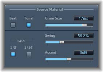
Chapter 14 Specialized eects and utilities 262
Grooveshifter
Grooveshifter allows you to rhythmically vary audio recordings, imparting a swing feel to the
input signal. Imagine a guitar solo played in straight eighth or sixteenth notes. Grooveshifter can
make this straightforward solo swing.
Grooveshifter automatically follows all changes to the project tempo, which it uses as the
reference tempo.
Note: Grooveshifter relies on perfect matching of the project tempo with the tempo of the
treated recording. Any tempo variations deliver less precise results.
Grooveshifter source material parameters
•Beat and Tonal buttons: Click to select the type of source, or input, material you are using.
•Beat button: The beat algorithm is optimized for percussive input material. The Grain Size
slider is disabled when you select Beat.
•Tonal button: The tonal algorithm is optimized for tonal input material. Because this
algorithm is based on granular synthesis, the Grain Size slider is available when you
select Tonal.
•Grain Size slider and eld: Drag to set the size of the grains—from 1 ms to 20 ms. Technically,
this determines the analysis precision. The default Auto setting at the left end of the slider
automatically assigns a suitable grain size value based on the incoming signal.
Grooveshifter swing parameters
•Grid buttons: Click to set the beat division used as a timing reference when analyzing
audio material.
•1/8 button: Select if the audio material contains primarily eighth notes.
•1/16 button: Select if the audio material consists mostly of sixteenth notes.
•Swing slider and eld: Drag to set the amount that even beats are delayed—from 50% to 75%.
A value of 50% means there is no swing, which is typical for most pop and rock music styles.
The higher the value, the stronger the swing eect.
•Accent slider and eld: Drag to set the level of even beats—from –12 dB to +12 dB—
suppressing or accentuating them. Such accents are typical of a variety of rhythmic styles,
such as swing or reggae.
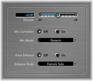
Chapter 14 Specialized eects and utilities 263
Speech Enhancer
You can use Speech Enhancer to improve speech recordings made with your computer’s internal
microphone, if applicable. It combines denoising, advanced microphone frequency remodeling,
and multiband compression.
Speech Enhancer parameters
•Denoise slider and eld: Drag to determine the noise oor in the recording—from –60 dB to
–20 dB—and thus the amount of noise reduction required. Settings toward –60 dB allow
more noise to pass; settings toward –20 dB increasingly suppress background noise but also
proportionately increase artifacts.
•Mic Correction O/On buttons: Click the On button to improve the frequency response
of recordings made with your built-in microphone, thus creating the impression that an
expensive microphone was used.
•Mic Model pop-up menu: Choose a microphone model to compensate for tonal characteristics
of specic built-in Mac microphones.
Note: You can use the Speech Enhancer eect with other microphones as well, but
microphone correction models are provided only for built-in Mac and iSight microphones.
If you are using a non-Apple microphone, choose Generic from the Mic Correction
pop-up menu.
•Voice Enhance O/On buttons: Click to turn the Voice Enhance multiband compression circuit
o or on.
•Enhance Mode pop-up menu: When Voice Enhance is active, choose an appropriate setting to
make the recorded voice louder and more intelligible:
•(Female or Male) Solo: Choose when the recorded signal consists of a vocal only.
•(Female or Male) Voice Over: Choose when the recorded signal contains both a vocal
performance and a musical or atmospheric bed.
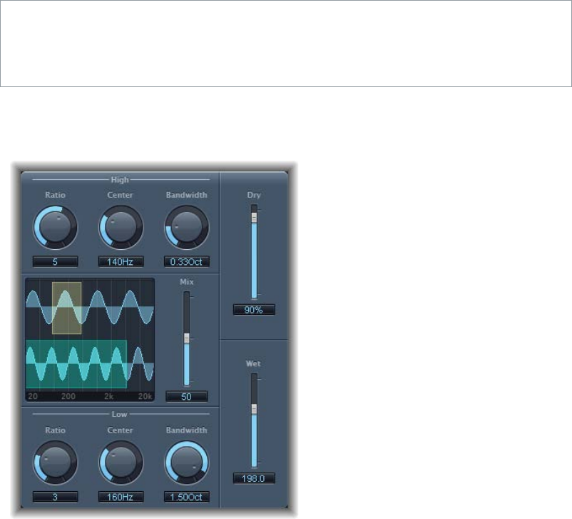
Chapter 14 Specialized eects and utilities 264
SubBass
SubBass overview
SubBass generates frequencies below those of the original signal, resulting in articial bass
content. The simplest use for SubBass is as an octave divider, similar to octaver eect pedals for
electric bass guitars. Whereas such pedals can only process a monophonic input sound source of
clearly dened pitch, SubBass can be used with complex summed signals as well.
SubBass creates two bass signals, derived from two separate portions of the incoming signal.
These are dened with the High and Low parameters. See SubBass parameters on page 264.
WARNING: Using SubBass can produce extremely loud output signals. Choose moderate
monitoring levels, and only use loudspeakers that are actually capable of reproducing the very
low frequencies produced. Never try to force a loudspeaker to output these frequency bands
with an EQ.
SubBass parameters
SubBass oers the following parameters.
SubBass parameters
•High Ratio knob and eld: Rotate to adjust the ratio between the generated signal and the
upper frequency band of the original signal.
•High Center knob and eld: Rotate to set the center frequency of the upper frequency band.
•High Bandwidth knob and eld: Rotate to set the width of the upper frequency band.
•Graphic display: Shows the selected upper and lower frequency bands.
•Freq. Mix slider and eld: Drag to adjust the mix ratio between the upper and lower
frequency bands.
•Low Ratio knob and eld: Rotate to adjust the ratio between the generated signal and the
lower frequency band of the original signal.
Chapter 14 Specialized eects and utilities 265
•Low Center knob and eld: Rotate to set the center frequency of the lower frequency band.
•Low Bandwidth knob and eld: Rotate to set the width of the lower frequency band.
•Dry slider and eld: Drag to set the amount of dry (non-eect, original) signal.
•Wet slider and eld: Drag to set the amount of wet (eect) signal.
SubBass use tips
Unlike a pitch shifter, SubBass generates a waveform that is not based on the waveform of the
input signal; instead it uses a sine wave. Given that pure sine waves rarely work well in complex
arrangements, make sure to use the Wet and Dry sliders to control the amount of—and balance
between—the generated and original signals.
Use the High parameters and the Low parameters to dene the two frequency bands that
SubBass uses to generate tones. High Center and Low Center dene the center frequency of each
band, and High Bandwidth and Low Bandwidth dene the width of each frequency band.
The High Ratio and Low Ratio knobs dene the transposition amount for the generated signal
in each band. This is expressed as a ratio of the original signal. For example, a Ratio value of 2
transposes the signal down one octave.
Important: Within each frequency band, the ltered signal should have a reasonably stable pitch
in order to be analyzed correctly.
In general, narrow bandwidths produce the best results, because they minimize frequency
intermodulations which can lead to unpleasant artifacts. Set the High Center knob value a fth
higher than Low Center, a factor of 1.5 for the center frequency.
Derive the sub-bass to be synthesized from the existing bass portion of the signal, and transpose
by one octave in both bands, using a Ratio of 2. Do not overdrive the process or you will
introduce distortion. If you hear frequency gaps, move one or both Center frequency knobs, or
widen the Bandwidth of one or both frequency ranges a little.
Tip: Be prudent when using SubBass, and compare the extreme low frequency content of
your mixes with other productions. It is very easy to over-enhance the low end of some tracks,
resulting in an unbalanced mix.
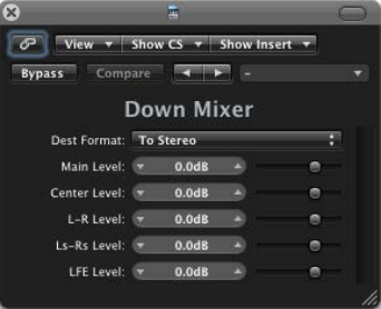
266
Utilities and tools overview
The tools found in the Utility category can help with routine tasks and situations you may
encounter during production. Examples include the Gain plug-ins, which you can use to adjust
the level or phase of input signals, and I/O Utility, which you can use to integrate external audio
eects into your host application mixer.
Down Mixer
You can use Down Mixer to adjust the input format of the surround master channel strip,
allowing you to quickly check a surround mix in stereo, for example.
Important: You choose the surround format you want from the Insert menu when you insert the
plug-in. Choices include: To Stereo, To Quad, and To LCRS.
Although channel mapping, panning, and downmixing are automatically handled behind the
scenes, you do have some control over the mix.
Use the Level sliders to control their respective channel levels. The number and the names of
sliders depend on the plug-in format you chose.
Utilities and tools 15
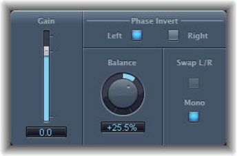
Chapter 15 Utilities and tools 267
Gain plug-in
Gain amplies (or reduces) the signal by a specic decibel amount. It is very useful for quick level
adjustments when you work with automated tracks during post-processing—for example, when
you have inserted an eect that doesn’t have its own gain control, or when you want to change
the level of a track for a remix version.
Gain plug-in parameters
•Gain slider and eld: Drag to set the amount of gain.
•Phase Invert Left and Right buttons: Turn on to invert the phase of the left and right channels,
respectively.
Inverting phase is useful for dealing with time alignment problems, particularly those caused
by simultaneous recording with multiple microphones. When you invert the phase of a signal
heard in isolation, it sounds identical to the original. When the signal is heard in conjunction
with other signals, however, phase inversion may have an audible eect. For example, if you
place microphones above and below a snare drum, you may nd that inverting the phase of
either microphone can improve (or ruin) the sound. As always, rely on your ears.
•Balance knob and eld: Rotate to adjust the balance of the incoming signal between the left
and right channels.
•Swap L/R (left/right) button: Turn on to swap the left and right output channels. The swapping
occurs after the Balance parameter in the signal path. The Swap L/R button is disabled when
the Mono button is turned on.
•Mono button: Turn on to output the summed mono signal on both the left and right channels.
Note: The Gain plug-in is available in mono, mono to stereo, and stereo instances. Only one
Phase Invert button is available in mono and mono to stereo modes. In mono mode, the Balance,
Swap L/R, and Mono parameters are disabled as well.
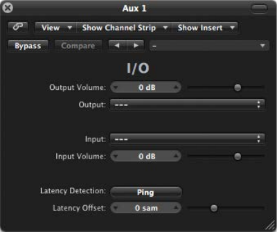
Chapter 15 Utilities and tools 268
Use I/O utility
I/O utility enables you to use external audio eects units, similar to using internal eects.
Note: I/O utility is not practical unless you are using an audio interface that provides discrete
inputs and outputs, either analog or digital, that are used to send signals to and from the
external audio eects unit.
I/O utility parameters
•Output Volume eld and slider: Drag to adjust the level of the output signal.
•Output pop-up menu: Choose the output, or output pair, of your audio hardware.
•Input pop-up menu: Choose the input, or input pair, of your audio hardware.
Note: The Input pop-up menu is visible only when an audio interface with multiple inputs
is active.
•Input Volume eld and slider: Drag to adjust the level of the input signal.
•Latency Detection (Ping) button: Click to detect the delay between the selected output and
input. Following detection, any delay is automatically compensated for.
Note: You can obtain the most accurate reading by bypassing any latency-inducing plug-ins
on the track.
•Latency Oset eld and slider: Displays the value for the detected latency between the selected
output and input in samples. You can also use this slider to oset the latency manually.
Use an external eects unit with I/O utility
1 Connect an output of your audio interface with the input on your eects unit, and connect the
output of your eects unit with an input on your audio interface.
Note: These can be either analog or digital connections, depending on the features of your
audio interface and eects unit, and each connection can be either an output or an output pair.
2 Click an Insert slot of an aux channel strip that is being used as a bus send/return, and choose
Utility > I/O.
3 In the I/O utility window, choose the Outputs and the Inputs of the audio hardware that your
eects unit is connected to.
4 Route the signals of any channel strips that you want to process to the bus (aux channel strip)
chosen in step 3, and set appropriate Send levels.
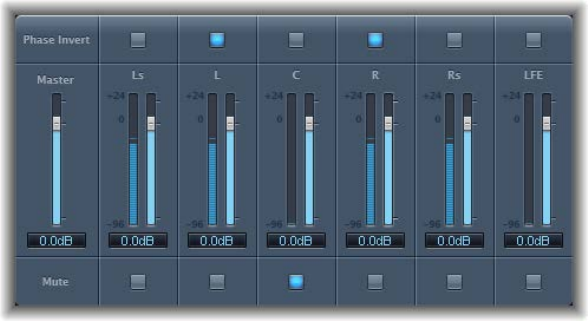
Chapter 15 Utilities and tools 269
5 Adjust the Input Volume and Output Volume sliders as required in the I/O utility window.
6 Click the Latency Detection (Ping) button if you want to detect and compensate for any delay
between the selected output and input.
When you start playback, the signals of any channel strips routed to the aux channel chosen in
step 3 are processed by the external eects unit.
Multichannel Gain
Multichannel Gain allows you to independently control the gain and phase of each channel in a
surround mix.
Multichannel Gain parameters
•Master slider and eld: Drag to set the master gain for the combined channel output.
•Channel gain sliders and elds: Drag to set the amount of gain for the respective channel.
•Phase Invert buttons: Click to invert the phase of the selected channel.
•Mute buttons: Click to mute the selected channel.
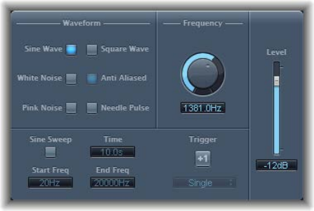
Chapter 15 Utilities and tools 270
Test Oscillator
Test Oscillator is useful for tuning studio equipment and instruments and can be inserted as both
an instrument or eect plug-in. It operates in two modes, generating either a static frequency or
a sine sweep.
In the rst mode, which is the default mode, it starts generating the test signal as soon as it is
inserted. You can switch it o by bypassing it. In the second mode, which is activated by clicking
the Sine Sweep button, Test Oscillator generates a user-dened frequency spectrum tone sweep
when triggered with the Trigger button.
Test Oscillator parameters
•Waveform buttons: Select the waveform to use for test tone generation. The Square Wave and
Needle Pulse waveforms are available as either aliased or anti-aliased versions—the latter
when used in conjunction with the Anti Aliased button; the Needle Pulse waveform is a single
needle impulse waveform.
Note: The Waveform buttons are disabled when the Sine Sweep button is turned on.
•Frequency knob and eld: Rotate to set the frequency of the oscillator (the default is 1 kHz).
•Sine Sweep button: Turn on to generate a sine wave sweep of the frequency spectrum you set
with the Start Freq and End Freq elds.
•Time eld: Drag to set the duration of the sine wave sweep.
•Start Freq(uency) and End Freq(uency) elds: Drag to set the oscillator frequency for the
beginning and end of the sine sweep.
•Sweep Mode pop-up menu (Extended Parameters area): Choose a type of sweep curve—Linear
or Logarithmic.
•Trigger button: Turn on to start the sine sweep.
•Trigger pop-up menu: Choose the sine sweep mode:
•Single: Triggers the sweep once.
•Continuous: Triggers the sweep indenitely.
•Level slider and eld: Drag to set the overall output level.
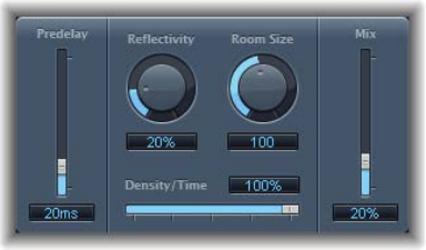
271
Legacy eects overview
Legacy eects are included for project compatibility. These plug-ins are inserted when you load a
project (that contains these plug-ins) created with an older Logic Pro version.
You can use these plug-ins or you can replace them with other eect plug-ins available in
Logic Pro.
You cannot directly insert these plug-ins in Logic Pro unless you override the eects
plug-in menu.
Display and insert legacy plug-ins in Logic Pro
1 Press Option, then click a plug-in slot on a channel strip.
The plug-in menu opens, with a Legacy submenu shown below the Utility plug-in submenu.
2 Choose the legacy plug-in that you want to insert from the Legacy submenu.
AVerb
AVerb is a basic reverb eect that employs a single parameter (Density/Time) to control both
the early reections and diuse reverb tail. It is a quick and easy tool for creating a range of
interesting space and echo eects.
AVerb parameters
•Predelay slider and eld: Drag to determine the time between the source signal and the early
reections of the reverb signal.
•Reectivity knob and eld: Rotate to dene how reective the imaginary walls, ceiling, and oor
are. In other words, how hard the walls are and what they are made of. Glass, stone, timber,
carpet, and other materials have a dramatic impact on the tone of the reverb.
•Room Size knob and eld: Rotate to dene the dimensions of simulated rooms.
•Density/Time slider and eld: Drag to determine both the density and duration of the reverb.
•Low values generate clearly discernible early reection clusters, resulting in an echo.
•High values result in a more reverb-like eect.
•Mix slider and eld: Drag to set the balance between the eect (wet) and direct (dry) signals.
Legacy eects
Appendix
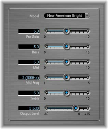
Appendix Legacy eects 272
Bass Amp
Bass Amp simulates the sound of several famous bass ampliers. You can route bass guitar and
other signals directly through Bass Amp, reproducing the sound of your musical part played
through a number of high-quality bass guitar amplication systems.
Bass Amp Parameters
•Model pop-up menu: Choose one of the following amplier models:
•American Basic: 1970s-era American bass amp, equipped with eight 10" speakers. Suitable for
blues and rock recordings.
•American Deep: Based on the American Basic amp, but with strong lower-mid frequency
(from 500 Hz on) emphasis. Suitable for reggae and pop recordings.
•American Scoop: Based on the American Basic amp, but combines the frequency
characteristics of the American Deep and American Bright, with both low-mid (from
500 Hz) and upper-mid (from 4.5 kHz) frequencies emphasized. Suitable for funk and
fusion recordings.
•American Bright: Based on the American Basic amp, this model emphasizes the upper-mid
frequencies (from 4.5 kHz upward).
•New American Basic: 1980s-era American bass amp, suitable for blues and rock recordings.
•New American Bright: Based on the New American Basic amp, this model emphasizes the
frequency range above 2 kHz. Suitable for rock and heavy metal.
•Top Class DI Warm: Famous DI box simulation, suitable for reggae and pop recordings. Mid
frequencies, in the range between 500 and 5000 Hz, are de-emphasized.
•Top Class DI Deep: Based on the Top Class DI Warm, this model is suitable for funk and fusion.
The mid frequency range is strongest around 700 Hz.
•Top Class DI Mid: Based on the Top Class DI Warm, this model features an almost linear
frequency range, with no frequencies emphasized. It is suitable for blues, rock, and
jazz recordings.
•Pre Gain slider: Sets the pre-amplication level of the input signal.
•Bass, Mid, and Treble sliders: Adjusts the bass, mid, and treble levels.
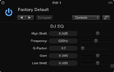
Appendix Legacy eects 273
•Mid Freq slider: Sets the center frequency of the mid band (between 200 Hz and 3000 Hz).
•Output Level slider: Sets the nal output level for Bass Amp.
EQ
DJ EQ
DJ EQ combines high and low shelving lters, each with a xed frequency, and one parametric
EQ. You can adjust the Frequency, Gain, and Q-Factor of the latter. The DJ EQ allows the lter gain
to be reduced by as much as −30 dB.
DJ EQ parameters
•High Shelf slider and eld: Drag to set the amount of gain for the high shelving lter.
•Frequency slider and eld: Drag to set the center frequency of the parametric EQ.
•Q-Factor slider and eld: Drag to set the range (bandwidth) of the parametric EQ.
•Gain slider and eld: Drag to set the amount of gain for the parametric EQ.
•Low Shelf slider and eld: Drag to set the amount of gain for the low shelving lter.
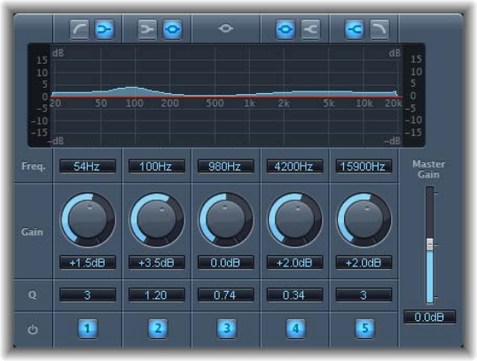
Appendix Legacy eects 274
Fat EQ
Fat EQ is a versatile multiband EQ that can be used on individual sources or overall mixes. Fat EQ
provides up to ve individual frequency bands, graphically displays EQ curves, and includes a set
of parameters for each band.
Fat EQ parameters
•Band Type buttons: For bands 1, 2, 4, and 5, click one of the paired buttons to select the
EQ type. Band 3 is parametric.
•Band 1: Click the highpass or low shelving button.
•Band 2: Click the low shelving or parametric button.
•Band 3: Always acts as a parametric EQ band.
•Band 4: Click the parametric or high shelving button.
•Band 5: Click the high shelving or lowpass button.
•Graphic display: Shows the EQ curve of each frequency band. The scale is shown in dB.
•Frequency elds: Drag to set the frequency for each band.
•Gain knobs and elds: Rotate to set the amount of gain for each band.
•Q elds: Drag to set the Q or bandwidth of each band—the range of frequencies around the
center frequency that are altered. At low Q factor values, the EQ covers a wider frequency
range. At high Q values, the eect of the EQ band is limited to a narrow frequency range. The
Q value can signicantly inuence how audible your changes are—if you are working with
a narrow frequency band, you will usually need to cut or boost more drastically to notice
the dierence.
Note: For bands 1 and 5, this changes the slope of the lter.
•Band On/O buttons: Turn the corresponding band on or o.
•Master Gain slider and eld: Drag to set the overall output level of the signal. Use it after
boosting or cutting individual frequency bands.
Appendix Legacy eects 275
Single-Band EQs
The single-band EQs are used for dierent types of equalization tasks.
•High Cut or Low Cut: High Cut attenuates the frequency range above the selected frequency.
Low Cut attenuates the frequency range that falls below the selected frequency.
•High Pass or Low Pass Filter: High Pass Filter aects the frequency range below the set
frequency. Higher frequencies pass through the lter. You can use High Pass Filter to eliminate
the bass below a selectable frequency. Low Pass Filter aects the frequency range above the
selected frequency.
•High Shelf or Low Shelf EQ: Low shelving EQ aects only the frequency range that falls
below the selected frequency. High shelving EQ aects only the frequency range above the
selected frequency.
•Parametric EQ: Parametric EQ is a simple lter with a variable center frequency. It can be used
to boost or cut any frequency band in the audio spectrum, either with a wide frequency range
or as a notch lter with a very narrow range. A symmetrical frequency range on either side of
the center frequency is boosted or cut.
High Cut and Low Cut parameters
•Frequency slider and eld: Drag to set the cuto frequency.
High Pass and Low Pass parameters
•Frequency slider and eld: Drag to set the cuto frequency.
•Order slider and eld: Drag to set the lter order. The more orders used, the stronger the
ltering eect.
•Smoothing slider and eld: Drag to adjust the amount of smoothing, in milliseconds.
High and Low Shelving EQ parameters
•Gain slider and eld: Drag to set the amount of cut or boost.
•Frequency slider and eld: Drag to set the cuto frequency.
Parametric EQ parameters
•Gain slider and eld: Drag to set the amount of cut or boost.
•Frequency slider and eld: Drag to set the cuto frequency.
•Q-Factor slider and eld: Drag to set the Q (bandwidth).
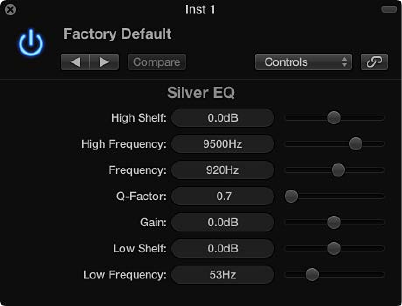
Appendix Legacy eects 276
Silver EQ
Silver EQ includes three bands—a high shelving EQ, a parametric EQ, and a low shelving EQ. You
can adjust the cuto frequencies for the high shelving and low shelving EQs. You can adjust the
center frequency, gain, and Q factor of the parametric EQ.
Silver EQ parameters
•High Shelf slider and eld: Drag to set the level of the high shelving EQ.
•High Frequency slider and eld: Drag to set the cuto frequency for the high shelving EQ.
•Frequency slider and eld: Drag to set the center frequency of the parametric EQ.
•Q-Factor slider and eld: Drag to set the range (bandwidth) of the parametric EQ.
•Gain slider and eld: Drag to set the amount of cut or boost for the parametric EQ.
•Low Shelf slider and eld: Drag to set the level of the low shelving EQ.
•Low Frequency slider and eld: Drag to set the cuto frequency for the low shelving EQ.
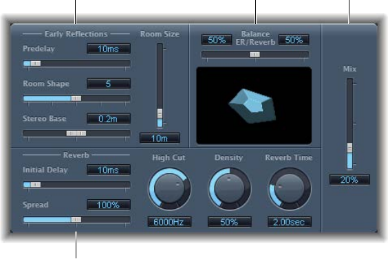
Appendix Legacy eects 277
GoldVerb
GoldVerb overview
GoldVerb allows you to edit both the early reections and diuse reverb tail separately, making it
easy to precisely emulate real rooms.
Balance
ER/Reverb slider
Early Reflections
parameters
Reverb parameters
Mix slider
and field
GoldVerb is divided into four parameter areas:
•Early reections parameters: Used to emulate the original signal’s rst reections as they
bounce o the walls, ceiling, and oor of a natural room. See GoldVerb early reections
parameters on page 278.
•Reverb parameters: Control the diuse reverberations. See GoldVerb reverb parameters on
page 279.
•Balance ER/Reverb slider: Drag to set the balance between the early reections and the reverb
signal. When the slider is set to either extreme position, the other signal is not heard.
•Mix slider and eld: Determines the balance between the eect (wet) and direct (dry) signals.
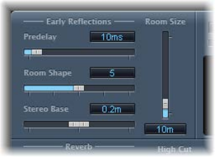
Appendix Legacy eects 278
GoldVerb early reections parameters
The GoldVerb provides the following Early Reections parameters.
GoldVerb early reections parameters
•Predelay slider and eld: Drag to set the time between the start of the original signal and the
arrival of the early reections.
•Extremely short: Predelay settings can color the sound and make it dicult to pinpoint the
position of the signal source.
•Very long: Predelay settings can be perceived as an unnatural echo and can divorce the
original signal from its early reections, leaving an audible gap between them.
•The optimum: Predelay setting depends on the type of input signal—or more precisely, the
envelope of the input signal. Percussive signals generally require shorter predelays than
signals where the attack fades in gradually. A good working method is to use the longest
possible Predelay value before you start to hear side eects, such as an audible echo. When
you reach this point, reduce the Predelay setting slightly.
•Room Shape slider and eld: Drag to dene the geometric form (the shape) of the room. The
numeric value (3 to 7) represents the number of corners in the room. The graphic display
visually represents this setting.
•Room Size slider and eld: Drag to determine the dimensions of the room. The numeric value
indicates the length of the room’s walls—the distance between two corners.
•Graphic display: Shows changes to Room Size and Room Shape parameters.
•Stereo Base slider and eld: Drag to set the distance between the two virtual microphones that
capture the simulated room signal.
Note: Spacing the microphones slightly farther apart than the distance between two human
ears generally delivers the best, and most realistic, results. This parameter is available only in
stereo instances of the eect.
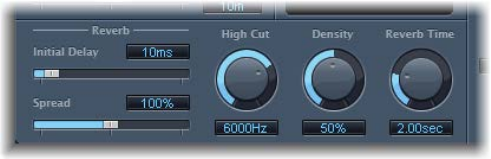
Appendix Legacy eects 279
GoldVerb reverb parameters
GoldVerb provides the following reverb parameters.
GoldVerb reverb parameters
•Initial Delay slider and eld: Drag to set the time between the original signal and the diuse
reverb tail. If you are trying to attain a natural-sounding, harmonic reverb, the transition
between the early reections and the reverb tail should be as smooth and seamless as
possible. Set the Initial Delay parameter so that it is as long as possible, without a noticeable
gap between the early reections and the reverb tail.
•Spread slider and eld: Drag to control the width of the reverb’s stereo image. At 0%, the eect
generates a monaural reverb. At 200%, the stereo base is articially expanded.
•High Cut knob and eld: Rotate to lter frequencies above the set value from the reverb signal.
Uneven or absorbent surfaces—wallpaper, wood paneling, carpets, and so on, tend to reect
lower frequencies better than higher frequencies. The High Cut lter mimics this eect. If you
set the High Cut lter to its maximum value, the reverb will sound as if it is reecting o stone
or glass.
•Density knob and eld: Rotate to control the density of the diuse reverb tail. Ordinarily you
want the signal to be as dense as possible. In rare instances, however, a high Density value
can color the sound, which you can x by reducing the Density knob value. Conversely, if you
select a Density value that is too low, the reverb tail will sound grainy.
•Reverb Time knob and eld: Rotate to set the time it takes for the reverb level to drop by
60 dB—often indicated as RT60. Most natural rooms have a reverb time somewhere in the
range of 1 to 3 seconds. This time is reduced by absorbent surfaces, such as carpet and
curtains, and soft or dense furnishings, such as sofas, armchairs, cupboards, and tables. Large
empty halls or churches have reverb times of up to 8 seconds, with some cavernous or
cathedral-like venues extending beyond that.
•Diusion slider and eld (Extended Parameters area): Sets the diusion of the reverb tail. High
Diusion values represent a regular density, with few alterations in level, times, and panorama
position over the course of the diuse reverb signal. Low Diusion values result in the
reection density becoming irregular and grainy. This also aects the stereo spectrum. As with
Density, nd the best balance for the signal.
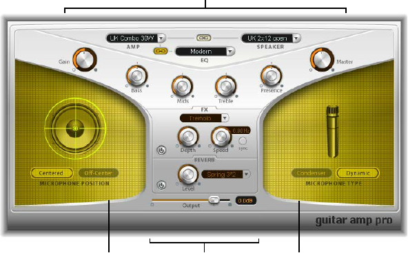
Appendix Legacy eects 280
Guitar Amp Pro
Guitar Amp Pro overview
Guitar Amp Pro simulates the sound of popular guitar ampliers and the speakers used with
them. You can process guitar signals directly, which enables you to reproduce the sound of your
guitar through a number of high-quality guitar amplication systems. Guitar Amp Pro can also
be used for experimental sound design and processing. You can use it with other instruments,
applying the sonic character of a guitar amp to a trumpet or vocal part, for example.
An amplier “model” consists of an amplier, speaker cabinet, EQ type, and microphone type.
You can create your own hybrids of dierent ampliers, cabinets, and so on—using the pop-up
menus at the top center of the interface. You choose the microphone position and type in the
yellow areas to the left and right. Guitar Amp Pro also emulates classic guitar amplier eects,
including reverb, vibrato, and tremolo.
You can use the Settings pop-up menu to save your new hybrid amp combos as setting les,
which also include any parameter changes you may have made.
The Guitar Amp Pro window is organized into several parameter sections.
Effects section
Amp section
Microphone
Position section
Microphone
Type section
•Amp section: The model parameters at the top are used to choose the type of amp, EQ model,
and speaker. The knobs in the V-shaped section are used to set tone, gain, and level. See Guitar
Amp Pro amplier models, Guitar Amp Pro cabinet models, and Guitar Amp Pro EQ.
•Eects section: Provides parameters to control the built-in tremolo, vibrato, and reverb eects.
See Guitar Amp Pro eects on page 283.
•Microphone Position and Type sections: These sections enable you to set the position and type
of the microphone. See Guitar Amp Pro microphone parameters on page 284.
•Output slider: The Output slider is found at the bottom, below the Eects section. It serves
as the nal level control for Guitar Amp Pro and can be thought of as a “behind the speaker”
volume control that is used to set the level fed to the ensuing plug-in slots on the channel
strip or to Output channel strips.
Note: This parameter is dierent from the Master control, which serves the dual purpose of
sound design as well as controlling the level of the Amp section.
Appendix Legacy eects 281
Guitar Amp Pro amplier models
You can choose an amplier model from the Amp pop-up menu near the top of the interface.
Amp models
•UK Combo 30W: Neutral-sounding amp, suitable for clean or crunchy rhythm parts.
•UK Top 50W: Quite aggressive in the high frequency range, suitable for classical rock sounds.
•US Combo 40W: Clean sounding amp model, suitable for funk and jazz sounds.
•US Hot Combo 40W: Emphasizes the high mid-frequency range, making this model ideal for
solo sounds.
•US Hot Top 100W: This amp produces very fat sounds, even at low Master settings, that result in
broad sounds with a lot of “oomph.”
•Custom 50W: With the Presence parameter set to 0, this amp model is suitable for smooth
fusion lead sounds.
•British Clean (GarageBand): Simulates the classic British Class A combos used continuously
since the 1960s for rock music, without any signicant modication. This model is ideally suited
for clean or crunchy rhythm parts.
•British Gain (GarageBand): Emulates the sound of a British tube head and is synonymous with
rocking, powerful rhythm parts and lead guitars with a rich sustain.
•American Clean (GarageBand): Emulates the traditional full tube combos used for clean and
crunchy sounds.
•American Gain (GarageBand): Emulates a modern Hi-Gain head, making it suitable for distorted
rhythm and lead parts.
•Clean Tube Amp: Emulates a tube amp model with very low gain (distortion only when using
very high input levels or Gain/Master settings).
Guitar Amp Pro cabinet models
The speaker cabinet can have a huge bearing on the type of tones you can extract from your
chosen amplier. The speaker parameters are found near the top of the interface.
Speaker cabinet parameters
•Speaker pop-up menu: You can choose one of the 15 speaker models:
•UK 1 x 12 open back: Classic open enclosure with one 12" speaker, neutral, well-balanced,
multifunctional.
•UK 2 x 12 open back: Classic open enclosure with two 12" speakers, neutral, well-balanced,
multifunctional.
•UK 2 x 12 closed: Loads of resonance in the low frequency range, therefore suitable for
Combos: crunchy sounds are also possible with low Bass control settings.
•UK 4 x 12 closed slanted: When used in combination with o-center miking, you will get an
interesting mid frequency range; therefore, this model works well when combined with High
Gain amps.
•US 1 x 10 open back: Not much resonance in the low frequency range. Suitable for use with
blues harmonicas.
•US 1 x 12 open back 1: Open enclosure of an American lead combo with a single 12" speaker.
•US 1 x 12 open back 2: Open enclosure of an American clean/crunch combo with a single 12"
speaker.
•US 1 x 12 open back 3: Open enclosure of another American clean/crunch combo with a
single 12" speaker.
Appendix Legacy eects 282
•US broad range: Simulation of a classic electric piano speaker.
•Analog simulation: Internal speaker simulation of a well-known British tube preamplier.
•UK 1 x 12 (GarageBand): A British Class A tube open back with a single 12" speaker.
•UK 4 x 12 (GarageBand): Classic closed enclosure with four 12" speakers (black series), suitable
for rock.
•US 1 x 12 open back (GarageBand): Open enclosure of an American lead combo with a single
12" speaker.
•US 1 x 12 bass reex (GarageBand): Closed bass reex cabinet with a single 12" speaker.
•DI Box: This option bypasses the speaker simulation section.
•Amp-Speaker Link button: Located between the Amp and Speaker pop-up menus, links these
pop-up menus so that when you change the amp model, the speaker associated with that
amp is loaded automatically.
Guitar Amp Pro EQ
The EQ pop-up menu and the Amp-EQ Link button are near the top of the interface.
EQ parameters
•EQ pop-up menu: Contains the following EQ models: British1, British2, American, and Modern.
Each EQ model has unique tonal qualities that aect the way the Bass, Mids, and Treble knobs
in the Amp section respond.
•Amp-EQ Link button: Located between the Amp and EQ pop-up menus, links these pop-up
menus so that when you change the amp model, the EQ model associated with that amp is
loaded automatically.
Each amp model has a speaker and EQ model associated with it. The default combinations
of amp, speaker, and EQ settings re-create a well-known guitar sound. You can combine any
speaker or EQ model with any amp by turning o the two Link buttons.
Guitar Amp Pro amplier controls
The Gain, Bass, Mids, Treble, Presence, and Master knobs run from left to right in the V-shaped
formation in the upper half of the interface.
Amplier parameters
•Gain knob: Sets the amount of pre-amplication applied to the input signal. This control has
dierent eects, depending on which Amp model is chosen. For example, when you are using
the British Clean amp model, the maximum Gain setting produces a powerful crunch sound.
If you use the British Gain or Modern Gain amps, the same Gain setting produces heavy
distortion, suitable for lead solos.
•Bass, Mids, and Treble knobs: Adjust the frequency range levels of the EQ models, similar to the
tone knobs on a hardware guitar amplier.
•Presence knob: Adjusts the high frequency range level. The Presence parameter aects only the
output (Master) stage of Guitar Amp Pro.
•Master knob: Sets the output volume of the amplier—going to the speaker. For tube
ampliers, increasing the Master level typically produces a more compressed and saturated
sound, resulting in a more distorted and powerful—that is, louder—signal. High Master
settings can produce an extremely loud output that can damage your speakers or hearing, so
ramp this up slowly. In Guitar Amp Pro, the Master parameter modies the sonic character, and
the nal output level is set using the Output parameter at the bottom of the interface.
Appendix Legacy eects 283
Guitar Amp Pro eects
The eects parameters include Tremolo, Vibrato, and Reverb, which emulate the processors found
on many ampliers.
You can use the pop-up menu to choose either Tremolo, which modulates the amplitude or
volume of the sound, or Vibrato, which modulates the pitch.
Reverb can be added to either of these eects, or used independently.
To use or adjust an eect, you must rst enable it by clicking the corresponding On button to the
left. The On button is red when active.
Note: The Eects section is placed before the Presence and Master controls in the signal ow, and
receives the preamplied, pre-Master signal.
Tremolo and vibrato parameters
•On/o button: Turns the tremolo/vibrato eect on or o.
•FX pop-up menu: You can choose either Tremolo or Vibrato.
•Depth knob: Sets the intensity of the modulation.
•Speed knob: Sets the speed of the modulation in Hertz. Lower settings produce a smooth and
oating sound, while higher settings produce a rotor-like eect.
•Sync button: When the Sync button is turned on, the modulation speed is synchronized to the
project tempo. You can adjust the Speed knob to select bar, beat, and musical note values
(including triplet and dotted notes). When the Sync button is turned o, the modulation speed
can be set to any available value with the Speed knob.
Reverb parameters
•On/o button: Turns the reverb eect on or o.
•Reverb pop-up menu: Choose one of the three types of spring reverb.
•Level knob: Rotate to set the amount of reverb applied to the pre-amplied amp signal.
Appendix Legacy eects 284
Guitar Amp Pro microphone parameters
After choosing a speaker cabinet from the Speaker menu, you can set the type of microphone
you want to be emulated, and where the microphone is placed in relation to the speaker. The
Microphone Position parameters are available in the yellow area to the left, and the Microphone
Type parameters in the yellow area to the right.
Microphone position parameters
•Centered button: Places the microphone in the center of the speaker cone, also called on-axis.
This placement produces a fuller, more powerful sound, suitable for blues or jazz guitar tones.
•O-Center button: Places the microphone on the edge of the speaker, also referred to as o-
axis. This placement produces a tone that is brighter and sharper, but also thinner—suitable
for cutting rock or R & B guitar parts.
When you select either button, the graphic speaker display reects your choice.
Microphone type parameters
•Condenser button: Emulates the sound of a studio condenser microphone. The sound of
condenser microphones is ne, transparent, and well-balanced.
•Dynamic button: Emulates the sound of a dynamic cardioid microphone. This microphone type
sounds brighter and more cutting than the Condenser model. At the same time, the lower-
mid frequency range is less pronounced, making this model more suitable for miking rock
guitar tones.
Tip: Combining both microphone types can sound quite interesting. Duplicate the guitar
track, and insert Guitar Amp Pro as an insert eect on both tracks. Select dierent microphone
types in each Guitar Amp Pro instance, while retaining identical settings for all other
parameters, and mix the track signal levels. You can also choose to vary any other parameters.
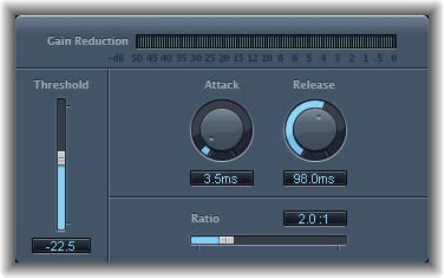
Appendix Legacy eects 285
Silver Compressor
Silver Compressor is a simplied version of the Compressor plug-in. See Use Compressor on
page 86.
Silver Compressor parameters
•Gain Reduction meter: Shows the amount of compression in real time.
•Threshold slider and eld: Drag to set the threshold level. Signals that exceed the threshold are
reduced in level.
•Attack knob and eld: Rotate to set the time it takes for Silver Compressor to react when the
signal exceeds the threshold.
•Release knob and eld: Rotate to set the time it takes for Silver Compressor to stop reducing the
signal, after the signal falls below the threshold.
•Ratio slider and eld: Drag to set the ratio by which the signal is reduced, when it exceeds
the threshold.
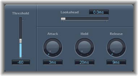
Appendix Legacy eects 286
Silver Gate
Silver Gate is a simplied version of the Noise Gate plug-in. See Use Noise Gate on page 99.
Silver Gate parameters
•Lookahead slider and eld: Drag to set how far ahead Silver Gate analyzes the incoming signal,
allowing it to respond more quickly to peak levels.
•Threshold slider and eld: Drag to set the threshold level. Signals that fall below the threshold
are reduced in level.
•Attack knob and eld: Rotate to set the time it takes to fully open the gate after the signal
exceeds the threshold.
•Hold knob and eld: Rotate to set the time the gate remains open after the signal falls below
the threshold.
•Release knob and eld: Rotate to set the time it takes to fully close the gate after the signal falls
below the threshold.
