Apple MainStage 3 Instruments User Manual Main Stage
MainStage - 3 - Instruments mainstage_3_instruments Free User Guide for Apple MainStage Software, Manual
2013-07-16
User Manual: Apple MainStage 3 MainStage 3 Instruments
Open the PDF directly: View PDF ![]() .
.
Page Count: 502 [warning: Documents this large are best viewed by clicking the View PDF Link!]
- MainStage 3 Instruments
- Contents
- Chapter 1: Drum Kit Designer
- Chapter 2: ES1
- Chapter 3: ES2
- ES2 overview
- ES2 interface
- ES2 sound sources
- ES2 oscillator parameters overview
- ES2 basic oscillator waveforms
- Use pulse width modulation in ES2
- Use frequency modulation in ES2
- Use ring modulation in ES2
- Use ES2 Digiwaves
- Use the ES2 noise generator
- ES2 emulation of detuned analog oscillators
- Stretch tuning in ES2
- Balance ES2 oscillator levels
- ES2 oscillator start points
- Synchronize ES2 oscillators
- ES2 global parameters
- ES2 filter parameters
- ES2 amplifier parameters
- ES2 modulation
- ES2 integrated effects processor
- ES2 macro controls and controller assignments
- ES2 extended parameters
- Create random ES2 sound variations
- ES2 tutorials
- Chapter 4: EFM1
- Chapter 5: ES E
- Chapter 6: ES M
- Chapter 7: ES P
- Chapter 8: EVOC 20 PolySynth
- EVOC 20 PolySynth and vocoding
- EVOC 20 PolySynth interface
- EVOC 20 PolySynth analysis parameters
- EVOC 20 PolySynth (U/V) detection parameters
- EVOC 20 PolySynth synthesis parameters
- EVOC 20 PolySynth formant filter
- EVOC 20 PolySynth modulation parameters
- EVOC 20 PolySynth output parameters
- EVOC 20 PolySynth performance tips
- Vocoder history
- EVOC 20 block diagram
- Chapter 9: EXS24 mkII
- EXS24 mkII overview
- Sampler instruments
- EXS24 mkII Parameter window
- EXS24 mkII Parameter window overview
- Sampler Instruments pop-up menu
- EXS24 mkII global parameters
- EXS24 mkII pitch parameters
- EXS24 mkII filter parameters
- EXS24 mkII output parameters
- EXS24 mkII extended parameters
- EXS24 mkII modulation overview
- EXS24 mkII modulation router
- EXS24 mkII LFOs
- EXS24 mkII envelope overview
- EXS24 mkII modulation reference
- EXS24 mkII Instrument Editor window
- EXS24 mkII preferences
- EXS24 mkII memory management
- Chapter 10: External Instrument
- Chapter 11: Klopfgeist
- Chapter 12: Retro Synth
- Retro Synth overview
- Retro Synth Analog oscillator controls
- Retro Synth Sync oscillator controls
- Retro Synth Table oscillator controls
- Retro Synth FM oscillator controls
- Retro Synth filter controls
- Retro Synth amp and effect controls
- Retro Synth modulation controls
- Retro Synth global and controller settings
- Retro Synth extended parameters
- Chapter 13: Sculpture
- Sculpture overview
- Sculpture interface
- Sculpture string parameters
- Sculpture objects parameters
- Sculpture pickups parameters
- Sculpture global parameters
- Sculpture amplitude envelope parameters
- Use Sculpture’s Waveshaper
- Sculpture filter parameters
- Sculpture delay effect parameters
- Sculpture Body EQ parameters
- Sculpture output parameters
- Sculpture modulation controls
- Sculpture morph parameters
- Define Sculpture MIDI controllers
- Sculpture tutorials
- Chapter 14: Ultrabeat
- Ultrabeat overview
- Ultrabeat interface
- Ultrabeat Assignment section
- Ultrabeat Synthesizer section overview
- Ultrabeat sound sources
- Ultrabeat oscillator overview
- Ultrabeat oscillator 1 phase oscillator mode
- Use Ultrabeat oscillator 1 FM mode
- Use Ultrabeat oscillator 1 side chain mode
- Use Ultrabeat oscillator 2 phase oscillator mode
- Basic waveform characteristics
- Use Ultrabeat oscillator 2 sample mode
- Use Ultrabeat oscillator 2 model mode
- Ultrabeat ring modulator
- Ultrabeat noise generator
- Use Ultrabeat’s filter section
- Ultrabeat distortion circuit
- Ultrabeat Output section
- Ultrabeat modulation
- Ultrabeat step sequencer
- Ultrabeat step sequencer overview
- Step sequencer basics
- Ultrabeat step sequencer interface
- Ultrabeat global sequencer controls
- Ultrabeat pattern controls
- Use Ultrabeat’s swing function
- Ultrabeat Step grid
- Automate parameters in Ultrabeat’s step sequencer
- Export Ultrabeat patterns as MIDI regions
- MIDI control of Ultrabeat’s step sequencer
- Ultrabeat tutorials
- Chapter 15: Vintage B3
- Chapter 16: Vintage Clav
- Chapter 17: Vintage Electric Piano
- Appendix A: Legacy instruments
- Appendix B: Synthesizer Basics

MainStage 3 Instruments
For OS X
100
KApple Inc.
Copyright © 2013 Apple Inc. All rights reserved.
Your rights to the software are governed by the accompanying
software license agreement. The owner or authorized user
of a valid copy of MainStage software may reproduce this
publication for the purpose of learning to use such software.
No part of this publication may be reproduced or transmitted
for commercial purposes, such as selling copies of this
publication or for providing paid for support services.
The Apple logo is a trademark of Apple Inc., registered in
the U.S. and other countries. Use of the “keyboard” Apple
logo (Shift-Option-K) for commercial purposes without the
prior written consent of Apple may constitute trademark
infringement and unfair competition in violation of federal and
state laws.
Every eort has been made to ensure that the information in
this manual is accurate. Apple is not responsible for printing or
clerical errors.
Because Apple frequently releases new versions and updates
to its system software, applications, and Internet sites, images
shown in this manual may be slightly dierent from what you
see on your screen.
Apple
1 Innite Loop
Cupertino, CA 95014
408-996-1010
www.apple.com
Apple, the Apple logo, Final Cut Pro, Finder, FireWire,
GarageBand, iMovie, iPad, iPhoto, iPod, iTunes, iTunes Store,
Jam Pack, Logic, Logic Pro, Mac, Macintosh, MainStage,
QuickTime, and Ultrabeat are trademarks of Apple Inc.,
registered in the U.S. and other countries.
IOS is a trademark or registered trademark of Cisco in the U.S.
and other countries and is used under license.
Other company and product names mentioned herein
are trademarks of their respective companies. Mention of
third-party products is for informational purposes only and
constitutes neither an endorsement nor a recommendation.
Apple assumes no responsibility with regard to the
performance or use of these products.
019-2556
Contents
14 Chapter 1: Drum Kit Designer
14 Drum Kit Designer overview
15 Drum Kit Designer Edit panel
16 Use Drum Kit Designer
19 Drum Kit Designer extended parameters
20 Drum Kit Designer mappings
21 Chapter 2: ES1
21 ES1 overview
22 ES1 oscillator parameters
22 ES1 oscillator parameters overview
23 ES1 oscillator waveforms
23 Use the ES1 sub-oscillator
24 ES1 global parameters
25 ES1 lter parameters
25 ES1 lter parameters overview
26 Drive the ES1 lter to self-oscillate
27 ES1 amplier parameters
28 ES1 envelope parameters
28 ES1 envelope parameters overview
28 ES1 lter cuto envelope modulation
29 ES1 amplier envelope modulation
30 ES1 modulation
30 ES1 modulation parameters overview
30 Use the ES1 router
31 Use the ES1 LFO
32 Use the ES1 modulation envelope
33 ES1 MIDI controllers
34 Chapter 3: ES2
34 ES2 overview
35 ES2 interface
37 ES2 sound sources
37 ES2 oscillator parameters overview
38 ES2 basic oscillator waveforms
39 Use pulse width modulation in ES2
40 Use frequency modulation in ES2
41 Use ring modulation in ES2
42 Use ES2 Digiwaves
42 Use the ES2 noise generator
43 ES2 emulation of detuned analog oscillators
44 Stretch tuning in ES2
3
45 Balance ES2 oscillator levels
45 ES2 oscillator start points
46 Synchronize ES2 oscillators
47 ES2 global parameters
47 Global parameters overview
48 Set the ES2 keyboard mode
48 Use unison and voices in ES2
49 Set the ES2 glide time
49 Set the ES2 pitch bend range
50 ES2 lter parameters
50 ES2 lter overview
51 ES2 lter conguration
51 Cross-fade between ES2 lters
53 ES2 Filter 1 modes
53 ES2 Filter 2 slopes
54 ES2 lter cuto and resonance
56 Overdrive ES2 lters
57 Modulate ES2’s Filter 2 Frequency
58 ES2 amplier parameters
58 Use ES2’s dynamic stage
58 Sine Level enhanced ES2 sounds
59 ES2 modulation
59 ES2 modulation overview
60 ES2 modulation router
64 ES2 LFOs
66 Use ES2 LFOs
67 ES2 envelopes
70 Use the Vector Envelope
71 Vector Envelope points, times, and loops
77 Use the Planar Pad
78 ES2 modulation target reference
84 ES2 modulation source reference
86 ES2 via modulation source reference
88 ES2 integrated eects processor
90 ES2 macro controls and controller assignments
90 ES2 macro and controller assignment overview
90 ES2 macro controls
91 Make ES2 controller assignments
92 ES2 extended parameters
92 Create random ES2 sound variations
92 Use ES2’s randomization parameters
93 Restriction of ES2 randomization
95 ES2 tutorials
95 Create ES2 sounds from scratch
106 Create ES2 sounds with templates
Contents 4
111 Chapter 4: EFM1
111 EFM1 overview
113 EFM1 modulator and carrier parameters
113 Modulator and carrier overview
115 Set the EFM1 tuning ratio
115 Choose a dierent EFM1 modulator waveform
116 EFM1 modulation parameters
117 EFM1 global parameters
118 EFM1 output parameters
119 Create random EFM1 sounds
119 EFM1 extended parameters
120 EFM1 MIDI controller assignments
121 Chapter 5: ES E
121 ES E overview
122 ES E oscillator parameters
123 ES E LFO parameters
124 ES E lter parameters
125 ES E envelope parameters
125 ES E output parameters
126 Extended ES E parameters
127 Chapter 6: ES M
127 ES M overview
128 ES M oscillator parameters
129 ES M lter and lter envelope
130 ES M level envelope and output controls
130 Extended ES M parameters
131 Chapter 7: ES P
131 ES P overview
132 ES P oscillator parameters
133 ES P LFO parameters
134 ES P lter parameters
135 ES P envelope and level controls
136 Integrated ES P eects processor
136 Extended ES P parameters
Contents 5
137 Chapter 8: EVOC 20 PolySynth
137 EVOC 20 PolySynth and vocoding
137 EVOC 20 PolySynth overview
138 Vocoder basics
139 EVOC 20 PolySynth interface
140 EVOC 20 PolySynth analysis parameters
141 EVOC 20 PolySynth (U/V) detection parameters
143 EVOC 20 PolySynth synthesis parameters
143 EVOC 20 PolySynth synthesis parameters overview
144 EVOC 20 PolySynth oscillator parameters
146 EVOC 20 PolySynth tuning and pitch parameters
147 EVOC 20 PolySynth lter parameters
147 EVOC 20 PolySynth envelope parameters
148 EVOC 20 PolySynth global parameters
149 EVOC 20 PolySynth formant lter
151 EVOC 20 PolySynth modulation parameters
152 EVOC 20 PolySynth output parameters
153 EVOC 20 PolySynth performance tips
153 Level and frequency tips
153 Tips to avoid sonic artifacts
154 Tips to enhance speech intelligibility
155 Vocoder history
156 EVOC 20 block diagram
157 Chapter 9: EXS24 mkII
157 EXS24 mkII overview
159 Sampler instruments
159 Sampler instruments overview
159 Sample storage locations
160 Manage sampler instruments
161 Use sampler instruments and settings
162 Import SoundFont2, DLS, and Gigasampler les
164 Convert audio regions to sampler instruments
165 Convert ReCycle les to sampler instruments
167 EXS24 mkII Parameter window
167 EXS24 mkII Parameter window overview
168 Sampler Instruments pop-up menu
171 EXS24 mkII global parameters
174 EXS24 mkII pitch parameters
176 EXS24 mkII lter parameters
178 EXS24 mkII output parameters
179 EXS24 mkII extended parameters
179 EXS24 mkII modulation overview
180 EXS24 mkII modulation router
184 EXS24 mkII LFOs
187 EXS24 mkII envelope overview
188 EXS24 mkII modulation reference
Contents 6
192 EXS24 mkII Instrument Editor window
192 EXS24 mkII Instrument Editor overview
193 EXS24 mkII Zones and Groups view
195 Create instruments, zones, and groups
199 Edit EXS24 mkII zones and groups
211 Save, rename, and export EXS24 mkII instruments
212 Edit samples in the Logic Pro Audio File Editor
213 Use an external instrument editor with EXS24 mkII
214 EXS24 mkII preferences
217 EXS24 mkII memory management
219 Chapter 10: External Instrument
219 External Instrument overview
220 Use the External Instrument
221 Chapter 11: Klopfgeist
221 Klopfgeist parameters
223 Chapter 12: Retro Synth
223 Retro Synth overview
224 Retro Synth Analog oscillator controls
225 Retro Synth Sync oscillator controls
226 Retro Synth Table oscillator controls
227 Retro Synth FM oscillator controls
229 Retro Synth lter controls
231 Retro Synth amp and eect controls
232 Retro Synth modulation controls
232 Use Retro Synth modulation
233 Retro Synth Glide and Autobend
234 Retro Synth LFO and Vibrato
235 Retro Synth envelopes
236 Retro Synth global and controller settings
237 Retro Synth extended parameters
238 Chapter 13: Sculpture
238 Sculpture overview
240 Sculpture interface
241 Sculpture string parameters
241 Sculpture string overview
242 Sculpture Hide, Keyscale, and Release view
243 Sculpture’s basic Material Pad parameters
244 Use Sculpture’s Material Pad in Keyscale or Release view
245 Use Sculpture’s string parameter sliders
247 Sculpture objects parameters
247 Sculpture objects overview
248 Sculpture excite table (objects 1 and 2)
250 Sculpture disturb and damp table (objects 2 and 3)
252 Sculpture pickups parameters
252 Use Sculpture pickup parameters
253 Sculpture’s spread controls
254 Sculpture global parameters
Contents 7
255 Sculpture amplitude envelope parameters
256 Use Sculpture’s Waveshaper
257 Sculpture lter parameters
258 Sculpture delay eect parameters
258 Sculpture delay eect overview
259 Sculpture’s Groove Pad (stereo)
260 Sculpture Body EQ parameters
260 Sculpture Body EQ overview
261 Use Sculpture’s Basic EQ model
262 Use Sculpture’s Body EQ models
263 Sculpture output parameters
263 Sculpture modulation controls
263 Sculpture modulation overview
264 Sculpture LFOs
268 Sculpture Vibrato parameters
269 Sculpture Jitter generators
270 Sculpture note-on random modulators
271 Sculpture velocity modulators
272 Use Controller A and B in Sculpture
272 Sculpture envelope parameters
280 Sculpture morph parameters
280 Sculpture morph overview
281 Use Sculpture’s Morph Pad
284 Use Sculpture’s Morph Envelope
289 Dene Sculpture MIDI controllers
290 Sculpture tutorials
290 Explore Sculpture
295 Create basic sounds in Sculpture
305 Advanced Sculpture tutorial: electric bass
323 Advanced Sculpture tutorial: synthesizer sounds
328 Chapter 14: Ultrabeat
328 Ultrabeat overview
329 Ultrabeat interface
330 Ultrabeat Assignment section
330 Ultrabeat Assignment section overview
331 Play and select Ultrabeat drum sounds
333 Name, swap, and copy Ultrabeat drum sounds
335 Import sounds and EXS instruments into Ultrabeat
337 Ultrabeat settings
338 Ultrabeat Synthesizer section overview
340 Ultrabeat sound sources
340 Ultrabeat oscillator overview
341 Ultrabeat oscillator 1 phase oscillator mode
342 Use Ultrabeat oscillator 1 FM mode
343 Use Ultrabeat oscillator 1 side chain mode
344 Use Ultrabeat oscillator 2 phase oscillator mode
345 Basic waveform characteristics
345 Use Ultrabeat oscillator 2 sample mode
Contents 8
347 Use Ultrabeat oscillator 2 model mode
349 Ultrabeat ring modulator
349 Ultrabeat noise generator
351 Use Ultrabeat’s lter section
354 Ultrabeat distortion circuit
355 Ultrabeat Output section
355 Ultrabeat Output section overview
356 Adjust Ultrabeat’s two-band EQ
357 Ultrabeat pan and stereo spread
358 Ultrabeat voice volume control
359 Change Ultrabeat’s trigger mode
360 Ultrabeat modulation
360 Ultrabeat modulation overview
360 Mod and via modulations in Ultrabeat
362 Create a modulation routing in Ultrabeat
363 Assign Ultrabeat MIDI controllers A–D
364 Use Ultrabeat LFOs
367 Ultrabeat envelope overview
368 Ultrabeat envelope parameters
369 Use Ultrabeat’s modulation target display
370 Ultrabeat step sequencer
370 Ultrabeat step sequencer overview
370 Step sequencer basics
371 Ultrabeat step sequencer interface
371 Ultrabeat global sequencer controls
372 Ultrabeat pattern controls
373 Use Ultrabeat’s swing function
374 Ultrabeat Step grid
378 Automate parameters in Ultrabeat’s step sequencer
380 Export Ultrabeat patterns as MIDI regions
381 MIDI control of Ultrabeat’s step sequencer
382 Ultrabeat tutorials
382 Ultrabeat sound programming overview
383 Create Ultrabeat kick drums
387 Create Ultrabeat snare drums
392 Create Ultrabeat tonal percussion
392 Create Ultrabeat hi-hats and cymbals
393 Create metallic Ultrabeat sounds
393 Tips for extreme Ultrabeat sounds
Contents 9
394 Chapter 15: Vintage B3
394 Vintage B3 overview
395 Vintage B3 Main window
395 Vintage B3 Main window overview
396 Vintage B3 draw bar controls
397 Vintage B3 Scanner Vibrato and Chorus
398 Vintage B3 Percussion eect
399 Use Vintage B3 preset keys
401 Set up Vintage B3 for your MIDI equipment
404 Vintage B3 Rotor Cabinet window
404 Vintage B3 Rotor Cabinet window overview
405 Advanced Cabinet parameters
406 Advanced Motor parameters
407 Advanced Brake parameters
408 Vintage B3 Microphone types
409 Vintage B3 Microphone parameters
410 Vintage B3 Options window
410 Vintage B3 Options window overview
410 Vintage B3 Master and Click controls
411 Vintage B3 Morph parameters
412 Use Vintage B3 Morph controls
413 Vintage B3 Eects window
413 Use Vintage B3 eects
414 Vintage B3 EQ
414 Vintage B3 Wah eect
416 Vintage B3 Distortion eect
416 Vintage B3 Reverb eect
417 Vintage B3 Expert window
417 Vintage B3 Expert window overview
418 Vintage B3 Pitch controls
419 Vintage B3 Sustain controls
419 Vintage B3 Condition controls
421 Vintage B3 Organ Model controls
422 Use a MIDI controller with Vintage B3
422 Choose a Vintage B3 MIDI control mode
422 Vintage B3 MIDI mode: Roland VK or Korg CX
424 Vintage B3 MIDI mode: Hammond Suzuki
425 Vintage B3 MIDI mode: Native Instruments B4D
427 Vintage B3 MIDI mode: Nord Electro
428 B3 and Leslie information
428 Additive synthesis with draw bars
429 The residual eect
429 Tonewheel sound generation
430 A brief Hammond history
431 The Leslie cabinet
Contents 10
432 Chapter 16: Vintage Clav
432 Vintage Clav overview
433 Vintage Clav interface
434 Vintage Clav Main window
434 Vintage Clav Main window overview
435 Vintage Clav models
436 Vintage Clav model characteristics
437 Use Vintage Clav Pickup parameters
438 Use Vintage Clav Stereo Spread parameters
439 Vintage Clav Eects window
439 Vintage Clav Eects window overview
440 Vintage Clav Compressor eect
440 Vintage Clav Distortion eect
441 Vintage Clav Modulation eect
442 Vintage Clav Wah eect
443 Vintage Clav Details window
443 Vintage Clav Details window overview
443 Vintage Clav Excite and Click parameters
444 Vintage Clav String parameters
445 Vintage Clav Pitch parameters
446 Vintage Clav Misc parameters
447 Vintage Clav extended parameters
448 D6 Clavinet information
448 D6 Clavinet history
449 D6 Clavinet mechanical details
450 Chapter 17: Vintage Electric Piano
450 Vintage Electric Piano overview
451 Vintage Electric Piano interface
452 Vintage Electric Piano Eects window
452 Vintage Electric Piano EQ
453 Vintage Electric Piano Drive eect
453 Vintage Electric Piano Chorus eect
454 Vintage Electric Piano Phaser eect
455 Vintage Electric Piano Tremolo eect
456 Vintage Electric Piano Details window
456 Vintage Electric Piano model parameters
457 Vintage Electric Piano pitch parameters
458 Vintage Electric Piano extended parameters
459 Vintage Electric Piano emulations
459 Rhodes models
460 Hohner and Wurlitzer models
461 Vintage Electric Piano MIDI controllers
Contents 11
462 Appendix A: Legacy instruments
462 Legacy instruments overview
462 Emulated instruments
462 Bass
462 Church Organ
463 Drum Kits
463 Electric Clav(inet)
463 Electric Piano
464 Guitar
464 Horns
464 Piano
464 Sound Eects
464 Strings
465 Tuned Percussion
465 Voice
465 Woodwind
465 Tonewheel Organ
466 Synthesizers
466 Analog Basic
466 Analog Mono
467 Analog Pad
467 Analog Swirl
468 Analog Sync
468 Digital Basic
469 Digital Mono
469 Digital Stepper
470 Hybrid Basic
471 Hybrid Morph
472 Appendix B: Synthesizer Basics
472 Synthesizer basics overview
473 Sound basics
473 Sound basics overview
474 Tones, overtones, harmonics, and partials
474 The frequency spectrum
475 Other waveform properties
476 Synthesizer fundamentals
478 Subtractive synthesizers
478 How subtractive synthesizers work
479 Subtractive synthesizer components
480 Oscillators
483 Filters
486 Envelopes in the amplier
488 Modulation
491 Global controls
Contents 12
492 Other synthesis methods
492 Other synthesis methods overview
492 Sample-based synthesis
493 Frequency modulation (FM) synthesis
494 Component modeling synthesis
495 Wavetable, Vector, and Linear Arithmetic synthesis
496 Additive synthesis
497 Phase distortion synthesis
497 Granular synthesis
498 A brief synthesizer history
498 Precursors to the synthesizer
499 Early voltage-controlled synthesizers
500 The Minimoog
501 Storage and polyphony
502 Digital synthesizers
Contents 13
14
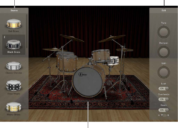
Drum Kit Designer overview
Drum Kit Designer lets you build custom drum kits from a wide selection of drum and percussion
sounds. It also provides controls that change sound characteristics and the level of each piece in
your kit.
Further settings allow you to use dierent microphones and rooms to enhance Producer kits.
Producer kits are identied in the Library by a “+” at the end of the patch name. See “Add
drummers to a project” in Logic Pro Help for information on Producer kits.
Edit panelExchange panel
Drum kit
Drum Kit Designer’s interface is divided into the following main areas.
•Drum kit: Click a drum kit piece to preview its sound and to open the Edit panel and the
Exchange panel if exchange pieces are available for that drum type.
•Exchange panel: Shows all drums that are available for exchange (you may need to scroll).
•Edit panel: Shows settings that change sound characteristics.
Drum Kit Designer 1

Chapter 1 Drum Kit Designer 15
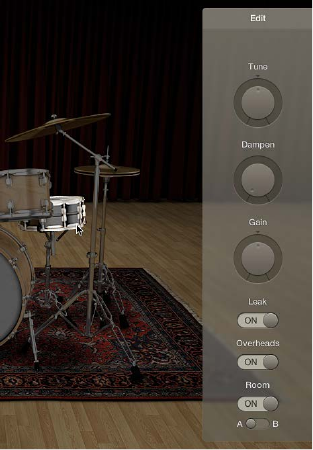
Drum Kit Designer Edit panel
The Edit panel is used to change sound characteristics and the level of each piece in your kit.
Edit panel parameters
•Tune knob and eld: Rotate to adjust the pitch.
•Dampen knob and eld: Rotate to adjust the sustain.
•Gain knob and eld: Rotate to adjust the volume.
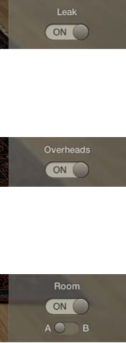
•Leak switch (Producer kits only): Drag to On to include the sound in the mic of the other
kit pieces.
•Overheads switch (Producer kits only): Drag to On to include the drum kit’s overhead mic in
the sound.
•Room switch (Producer kits only): Drag to choose between rooms A and B or to turn o the
room emulation.
Chapter 1 Drum Kit Designer 16
Use Drum Kit Designer
Drum Kit Designer shows a 3D representation of the drum kit for the currently loaded patch.
For all kits, you can preview the drums, edit the pitch, sustain, and volume of each drum kit piece,
and exchange the kick and snare drums. When working with Producer kits, you can additionally
exchange toms, cymbals, and hi-hat. Producer kits let you turn dierent microphones, such as
overheads or room mics, on or o.
Note: Producer kits and some drums are only available after you download additional content.
Drum Kit Designer also has additional parameters for adjusting the gain of other instrument
pieces, such as shaker, cowbell, and so on. See Drum Kit Designer extended parameters.
Preview a drum or percussion piece
mClick a drum or percussion piece.
The rst time you click any drum or percussion piece after opening the plug-in, one or two
panes open. You can exchange individual sounds in the Exchange panel to the left and can edit
individual drum or percussion piece settings in the Edit panel to the right.
Adjust kit piece settings (all kits)
1 Click a drum or percussion piece.
The Edit panel opens to the right.
•Toms: Click the tab for the tom you want to edit, or click the All tab to adjust the tone of
all toms.
•Cymbals: Click the tab for the crash cymbal you want to edit, or click the All tab to adjust the
tone of both crash cymbals. The ride cymbal can be edited directly.
•Kicks and snares: There are no tabs, so make your adjustments with the controls.

Chapter 1 Drum Kit Designer 17
2 To adjust settings, do any of the following:
•To adjust the pitch: Drag the Tune control vertically, or double-click the eld and enter a
new value.
•To adjust the sustain: Drag the Dampen control vertically, or double-click the eld and enter a
new value.
•To adjust the volume: Drag the Gain control vertically, or double-click the eld and enter a
new value.
3 To close open panels, click anywhere in the plug-in window background.
Exchange a kit piece
For all kits, you can exchange kick and snare. When working with Producer kits, you can
additionally exchange toms, cymbals, and hi-hat.
Note: Producer kits and some drums are only available after you download additional content.
1 Click a drum or percussion piece.
The Exchange panel opens to the left if exchange pieces are available for that kit piece.
2 Click the Info button of a selected piece to view its description.
3 Click the kit piece that you want to exchange in the Exchange panel. You may need to scroll in
order to nd the piece you want to use.
The piece is exchanged and the respective drum sound is loaded.
Note: The toms and the crash cymbals can only be exchanged as a group.
Chapter 1 Drum Kit Designer 18
4 To close the panels, click anywhere in the plug-in window background.
Adjust mic settings (Producer kits only)
In the Edit panel, do any of the following:
mTo include the sound in the mic of the other kit pieces: Turn on the Leak switch.
This turns microphone bleed on or o, where the sound of a kit piece is picked up by the
dierent mics from other kit pieces.
mTo include the kit piece’s overhead mic in the sound: Turn on the Overheads switch.
This turns the overhead mic for the selected kit piece on or o.
mTo choose a room emulation to use with the sound: Choose between rooms A and B. You can also
turn o the room microphones.
Rooms A and B determine which room mic setup is used with the kit piece.
Chapter 1 Drum Kit Designer 19
Drum Kit Designer extended parameters
Drum Kit Designer provides additional parameters that are accessed by clicking the disclosure
triangle at the lower left.
The Input Mapping pop-up menu lets you choose dierent mappings that provide enhanced
control of HiHats. The maps also change the way Drum Kit Designer sounds are assigned across
the MIDI note range. See Drum Kit Designer mappings.
Extended parameters
•Input Mapping pop-up menu: Choose a keyboard mapping mode.
•GM: Drums are mapped to the GM standard.
•GM + ModWheel controls HiHat opening level: The keyboard Mod Wheel is mapped for
hi-hat control. Additional sounds are also mapped to keyboard zones above and below the
standard GM note mapping range.
•V-Drum: Drums are mapped to work with V-Drum hi-hat, cymbal, and drum triggers.
•Gain sliders: Drag the slider (or drag vertically in the eld) to adjust the level of the
corresponding sound (if available in the kit).
•Shaker Gain
•Tambourine Gain
•Claps Gain
•Cowbell Gain
•Sticks Gain
Chapter 1 Drum Kit Designer 20
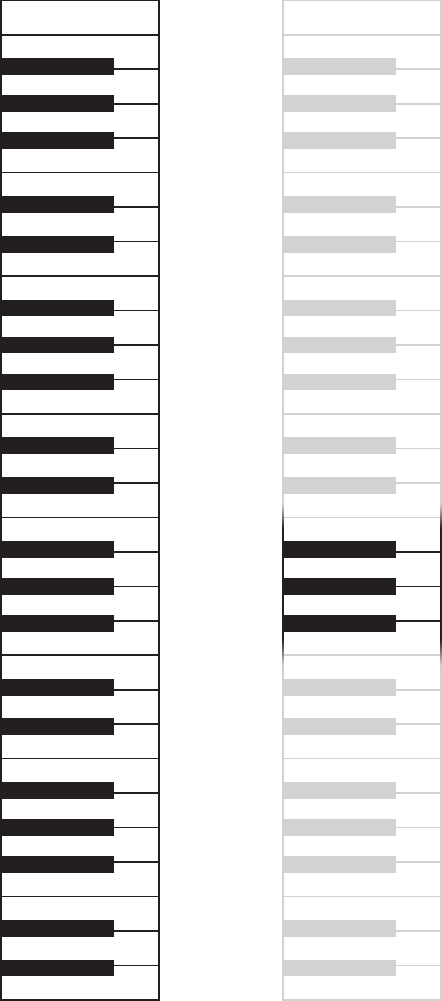
Drum Kit Designer mappings
Drum Kit Designer is compatible with the GM standard. You can also choose GM+, which maps
the keyboard ModWheel for hi-hat control. This means that you can use the keyboard ModWheel
to adjust the degree to which the hi-hat opens and closes during the drum performance.
Drum Kit Designer is also compatible with the V-Drum standard.
The image shows how drum sounds are remapped when dierent modes are chosen with the
Input Mapping pop-up menu in the extended parameters.
Note: A number of alias drums sounds are included for GM compatibility purposes.
Shaker
C3
Ride In
Crash Right
Ride Bell
Ride Edge
High Tom
High Tom
C2
High Mid Tom
Low Mid Tom
Low Tom
Low Tom
Snare Rimshot
Snare Center
Kick
C1
C0
Kick
Hi-Hat Foot Close
Hi-Hat Foot Splash
Crash Right Stop
Crash Left Stop
Cowbell
Tambourine
Ride Out
Crash Left
Hi-Hat Open Edge
Hi-Hat Foot
Hi-Hat Closed Tip
C2
Hi-Hat Edge
Hi-Hat Shank
Hi-Hat Tip
Claps
Snare Sidestick
Snare Edge
Rimshot Edge
Shaker
C3
Ride In
Crash Right
Ride Bell
Ride Edge
High Tom
High Tom
High Mid Tom
Low Mid Tom
Low Tom
Low Tom
Snare Rimshot
Snare Center
Kick
C1
C0
Kick
Hi-Hat Foot Close
Hi-Hat Foot Splash
Crash Right Stop
Crash Left Stop
Cowbell
Tambourine
Ride Out
Crash Left
Claps
Snare Sidestick
Snare Edge
Rimshot Edge
GM Standard GM + ModWheel

21
ES1 overview
ES1 emulates the circuits of analog synthesizers in a simple, streamlined interface.
ES1 produces sounds using subtractive synthesis. It provides an oscillator and sub-oscillator
that generate harmonically rich waveforms. You subtract (cut, or lter out) portions of these
waveforms and reshape them to create new sounds. The ES1’s tone-generation system also
provides exible modulation options that make it easy to create punchy basses, atmospheric
pads, biting leads, and sharp percussion.
If you’re new to synthesizers, see Synthesizer basics overview on page 472, which will introduce
you to the terminology and give you an overview of dierent synthesis systems and how
they work.
Global parameters
Envelope parameters
Modulation parameters
Amplifier parameters
Filter parameters
Oscillator parameters
ES1 is divided into six main areas.
•Oscillator parameters: Located in the upper left, the oscillators generate the basic waveforms
that form the basis of your sound. See ES1 oscillator parameters overview on page 22.
•Global parameters: Located in the bottom green/gray strip, global sound control parameters
are used to assign and adjust global tuning, activate the in-built chorus, and so on. You can
use the chorus to color or thicken the sound. See ES1 global parameters on page 24.
•Filter parameters: Located in the upper-middle section with the circular Filter area as well as the
Drive and Key scaling parameters, the lter is used to contour the waveforms sent from the
oscillators. See ES1 lter parameters overview on page 25.
•Amplier parameters: Located in the upper right, the amplier parameters allow you to ne-
tune the behavior of your sound’s level. See ES1 amplier parameters on page 27.
•Envelope parameters: Located to the right in the dark green/gray area, the ADSR sliders
are used to control both lter cuto and the amplier level over time. See ES1 envelope
parameters overview on page 28.
ES1 2
Chapter 2 ES1 22
•Modulation parameters: Located to the left and middle in the dark green/gray area, the
modulation sources, modulation router, modulation envelope, and amplitude envelope
are used to modulate the sound in a number of ways. See ES1 modulation parameters
overview on page 30.
ES1 oscillator parameters
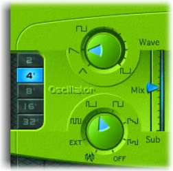
ES1 oscillator parameters overview
ES1 includes a primary oscillator and a sub-oscillator. The primary oscillator generates a
waveform that is sent to other parts of the synthesizer for processing or manipulation.
The sub-oscillator generates a secondary waveform one or two octaves below that of the
primary oscillator.
Oscillator parameters
•Wave knob: Rotate to select the waveform of the primary oscillator, which is responsible for the
basic color of the tone. See ES1 oscillator waveforms on page 23.
•Mix slider: Drag to set the level relationship between the primary and sub-oscillator signals.
(When the sub-oscillator is switched o, its output is completely removed from the signal
path.)
•Sub knob: Rotate to generate square, pulse, and white-noise waveforms with the sub-oscillator.
The sub-oscillator also allows you to route a side-chain signal through the ES1 synthesizer
engine. See Use the ES1 sub-oscillator on page 23.
•2’, 4’, 8’, 16’, and 32’ buttons: Click to transpose the pitch of the oscillators up or down by octaves.
The lowest setting is 32 feet and the highest is 2 feet. The use of the term feet to determine
octaves comes from the measurements of organ pipe lengths. The longer and wider the pipe,
the deeper the tone.
Modulate ES1 pulse width
mRotate the Wave knob to a position between the square wave and pulse wave symbols.
The pulse width can also be automatically modulated in the modulation section (see Use the ES1
router on page 30). Modulating the pulse width with a slowly cycling LFO, for example, allows
periodically mutating, fat bass sounds.

Chapter 2 ES1 23
ES1 oscillator waveforms
The table outlines the basic tones of the oscillator waveforms—how they aect your
synthesizer sound.
Waveform Basic tone Comments
Sawtooth Warm and even Useful for strings, pads, bass, and
brass sounds
Triangle Sweet sounding, softer than
sawtooth
Useful for utes, pads
Square Hollow and “woody” sounding Useful for basses, clarinets, and
oboes
Pulse “Nasal” sounding Great for reed instruments, synth
blips, basses
Use the ES1 sub-oscillator
The ES1 sub-oscillator is used to make your sound richer. Its pitch matches the frequency of the
main oscillator. You can choose from the following sub-oscillator waveform options:
•A square wave that plays one or two octaves below the frequency of the primary oscillator
•A pulse wave that plays two octaves below the frequency of the primary oscillator
•Variations of these waveforms, with dierent mixes and phase relationships, resulting in
various sounds
•White noise, which is useful for creating percussion sounds as well as wind, surf, and rain
sounds
•OFF, which allows you to disable the sub-oscillator
•EXT, which allows you to run an external channel strip signal through the ES1 synthesizer
engine, by using a side chain
Process a channel strip signal through the ES1 synthesizer engine
1 Set the Sub knob to EXT.
2 Choose the side-chain source channel strip from the Side Chain pop-up menu in the upper-right
corner of ES1.

Chapter 2 ES1 24
ES1 global parameters
The global parameters aect the overall sound, or behavior, of the ES1 and are found primarily in
the strip that spans the lower edge of the ES1 interface. The Glide slider is displayed above the
left end of the strip.
Global parameters
•Glide slider: Drag to set the amount of time it takes to slide between the pitches of each
triggered note. The Glide trigger behavior depends on the value set in the Voices eld (see
below).
•Tune eld: Drag to tune the instrument in cents. One cent is 1/100th of a semitone.
•Analog eld: Drag to slightly, and randomly, change the pitch of each note and the cuto
frequency. This emulates the oscillator detuning and lter uctuations of polyphonic analog
synthesizers, due to heat and age.
If you set the Analog parameter to 0%, the oscillator cycle start points of all triggered voices
are synchronized. This can be useful for percussive sounds, when you want to achieve a
sharper attack characteristic.
If you set the Analog parameter higher than 0%, the oscillators of all triggered voices can
cycle freely. Use higher values if you want a warm, analog type of sound—where subtle sonic
variations occur for each triggered voice.
•Bender Range eld: Drag to set the sensitivity of the pitch bender, in semitone steps.
•Neg Bender Range slider (Extended Parameters area): Drag to set the negative (downward)
pitch bend range in semitone steps. The default value is Pos PB (positive pitch bend), which
essentially means that there is no downward pitch bend available. (Click the disclosure triangle
at the lower left of the ES1 interface to access the Extended Parameters area.)
•Out Level eld: Drag to set the ES1 master volume.
•Voices eld: Drag to set the maximum number of notes that can be played simultaneously—up
to 16 voices.
When Voices is set to Legato, the ES1 behaves like a monophonic synthesizer—with single
trigger and ngered portamento engaged. This means that if you play legato, a portamento—
glide from one note to the next—will happen. If you release each key before pressing a
new one, the envelope is not triggered by the new note, and there is no portamento. Use
this feature to create pitch bend eects, without touching your keyboard’s pitch bender, by
choosing a high Glide parameter value when using the Legato setting.
•Chorus eld: Click to choose a classic stereo chorus eect, an ensemble eect, or to disable the
eects processor.
•O disables the built-in chorus circuit.
•C1 is a typical chorus eect.
•C2 is a variation of C1 and is characterized by a stronger modulation.
•Ens(emble) uses a more complex modulation routing, creating a fuller and richer sound.
Chapter 2 ES1 25
ES1 lter parameters
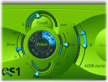
ES1 lter parameters overview
This section outlines the lter parameters of the ES1.
Filter parameters
•Cuto slider: Drag to set the cuto frequency of the ES1’s lowpass lter.
•Resonance slider: Drag to cut or boost the portions of the signal that surround the frequency
dened by the Cuto parameter. Boost can be set so intensively that the lter begins to
oscillate by itself (see Drive the ES1 lter to self-oscillate on page 26).
Tip: You can simultaneously adjust the cuto frequency and resonance parameters by
dragging vertically (cuto) or horizontally (resonance) on the word Filter, found in the center
of the black circle.
•Slope buttons: The lowpass lter oers four dierent slopes of band rejection above the cuto
frequency. Click one of the buttons to choose a slope (amount of rejection, expressed in
decibels (dB) per octave):
•24 dB classic: Mimics the behavior of a Moog lter. Turning up the resonance results in a
reduction of the low end of the signal.
•24 dB fat: Compensates for the reduction of low frequency content caused by high
Resonance values. This resembles the behavior of an Oberheim lter.
•12 dB: Provides a soft, smooth sound that is reminiscent of the early Oberheim
SEM synthesizer.
•18 dB: Resembles the lter sound of Roland’s TB-303.
•Drive slider: Drag to change the behavior of the Resonance parameter, which eventually
distorts the sound of the waveform. Drive is actually an input level control, which allows you
to overdrive the lter.
•Key slider: Drag to set the eect that keyboard pitch (the note number) has on lter cuto
frequency modulation.
•If Key is set to zero, the cuto frequency does not change, no matter which key you strike.
This makes the lower notes sound comparatively brighter than higher notes.
•If Key is set to maximum, the lter follows the pitch, resulting in a constant relationship
between cuto frequency and pitch. This mirrors the properties of many acoustic
instruments, where higher notes sound both brighter in tone and higher in pitch.
Chapter 2 ES1 26
•ADSR via Vel sliders: Drag to determine how note velocity aects modulation of the lter cuto
frequency with the envelope generator. See ES1 envelope parameters overview on page 28.
•Filter Boost button (Extended Parameters area): Turn on to increase the output of the lter by
approximately 10 decibels. The lter input has a corresponding decrease of approximately 10
decibels, maintaining the overall level. This parameter is particularly useful when applying high
Resonance values. See Drive the ES1 lter to self-oscillate. (Click the disclosure triangle at the
lower left of the ES1 interface to access the Extended Parameters area.)
Drive the ES1 lter to self-oscillate
If you increase the lter Resonance parameter to higher values, the lter begins to internally
feed back and, as a consequence, begins to self-oscillate. This results in a sine oscillation—a sine
wave—that is actually audible.
You can make the ES1 lter output a sine wave by following the steps below. This lets you play
the lter-generated sine wave with the keyboard.
Output a sine wave from the lter
1 Switch the Sub knob to O.
2 Drag the Mix slider to the very bottom (Sub).
3 Drag the Resonance slider to the maximum position (full).
4 If you want, click the disclosure triangle at the lower left to open the extended parameters, then
click the Filter Boost button.
Filter Boost increases the output of the lter by approximately 10 decibels, making the self-
oscillation signal much louder.

Chapter 2 ES1 27
ES1 amplier parameters
The parameters in the ES1 Amplier section allow you to ne-tune the behavior of your sound’s
level. These are separate from the global Out Level parameter, which acts as the ES1’s master
volume control. See ES1 global parameters on page 24.
Amplier parameters
•Level via Vel slider: Drag to determine how note velocity aects the synthesizer level. The
greater the distance between the arrows (indicated by the blue bar), the more the volume is
aected by incoming velocity messages.
•Drag the upper arrow to set the level when you play hard (velocity=127).
•Drag the lower arrow to set the level when you play softly (velocity=1).
•To simultaneously adjust the modulation range and intensity, drag the blue bar—between
the arrows—and move both arrows at once.
•Amplier envelope selector buttons: Click one of the buttons—AGateR, ADSR, or GateR—to
determine the ADSR envelope generator used for control of the amplier envelope. See ES1
envelope parameters overview on page 28.

Chapter 2 ES1 28
ES1 envelope parameters
ES1 envelope parameters overview
ES1 provides an attack, decay, sustain, and release (ADSR) envelope that can shape lter cuto
and the level of the sound over time.
Envelope Parameters
•A(ttack) slider: Drag to set the time it takes for the envelope to reach the initial desired level.
•D(ecay) slider: Drag to set the time it takes for the envelope to fall to the sustain level, following
the initial attack time.
•S(ustain) slider: Drag to set the sustain level, which is held until the key is released.
•R(elease) slider: Drag to set the time it takes the envelope to fall from the sustain level to a level
of 0.
ES1 lter cuto envelope modulation
The envelope generator modulates the lter cuto frequency over the course of a note’s
duration. The modulation intensity—and response to velocity information—is set by the arrows
on the ADSR via Vel slider in the Filter section.
ADSR via Vel slider
The modulation range is determined by the two arrows.
•The lower arrow indicates the minimum amount of modulation.
•The upper arrow indicates the maximum amount of modulation.
•The blue bar between the arrows shows the dynamic range of this modulation. You can
simultaneously adjust the modulation range and intensity by dragging the blue bar.
Tip: If you’re unfamiliar with these parameters, set the Cuto parameter to a low value,
Resonance to a high value, and move both ADSR via Vel arrows upward. Constantly strike a note
on the keyboard while changing the arrows to learn how these parameters work.

Chapter 2 ES1 29
ES1 amplier envelope modulation
The AGateR, ADSR, and GateR buttons in the Amplier section determine which of the ADSR
envelope controls aect the amplier envelope. All ADSR parameters remain active for the lter.
The letters A, D, S, and R refer to the attack, decay, sustain, and release phases of the envelope
(see ES1 envelope parameters overview on page 28).
Gate refers to a control signal used in analog synthesizers that is sent to an envelope generator
when a key is pressed. As long as an analog synthesizer key is pressed, the gate signal maintains
a constant voltage. When Gate is used as a modulation source in the voltage-controlled amplier
(instead of the envelope), it creates an organ-type envelope without any attack, decay, or release
phase—in other words, an even, sustained sound.
Amplifier Envelope
Selector buttons
The ES1 amplier envelope selector buttons have the following eect on played notes:
•AGateR: The Attack and Release sliders of the ADSR envelope control the attack and release
phases of the sound. In-between these phases, the Gate control signal is used to maintain a
constant level while a note is held. As soon as you release the key, the release phase begins.
The Decay and Sustain sliders of the ADSR Envelope have no impact on the sound’s level.
•ADSR: The standard operating mode of most synthesizers, where the level of the sound over
time is controlled by the ADSR Envelope.
•GateR: The Gate control signal is used to maintain a constant level while a note is held. As soon
as you release the key, the release phase begins. The Attack, Decay, and Sustain sliders of the
ADSR Envelope have no impact on the sound’s level.
Chapter 2 ES1 30
ES1 modulation
ES1 modulation parameters overview
ES1 oers a number of simple yet exible modulation routing options. You use modulation to
add animation to your sound over time, making it more interesting, lively, or realistic. A good
example of this type of sonic animation is the vibrato used by orchestral string players.
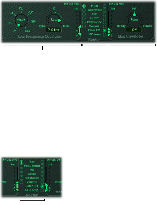
Modulation EnvelopeRouterLFO parameters
Modulation parameters
•LFO parameters: Used to modulate other ES1 parameters. See Use the ES1 LFO on page 31.
•Router: Enables you to choose the ES1 parameters that are modulated. See Use the ES1
router on page 30.
•Modulation Envelope: A dedicated modulation control source that can be used to control
various ES1 parameters, or it can be used to control the LFO level. See Use the ES1 modulation
envelope on page 32.
Use the ES1 router
The router determines the ES1 parameters (targets) that are modulated by the LFO and by the
modulation envelope. The buttons in the left column set the target for LFO modulation. The
buttons in the right column set the target for the modulation envelope.
Parameter target
buttons
Router parameters
•Pitch buttons: Click to modulate the pitch—the frequency—of the oscillators.
•Pulse Width buttons: Click to modulate the pulse width of the pulse wave.
•Mix buttons: Click to modulate the mix between the primary oscillator and the sub-oscillator.
•Cuto buttons: Click to modulate the cuto frequency of the lter.
•Resonance buttons: Click to modulate the resonance of the lter.
•Volume buttons: Click to modulate the main volume.
•Filter FM button (modulation envelope only): Click to use the triangle wave of the oscillator
to modulate lter cuto frequency. This modulation can result in a pseudo-distortion of the
sound, or it can create metallic, FM-style sounds. The latter occurs when the only signal you
can hear is the self-oscillation of the resonating lter (see Drive the ES1 lter to self-oscillate on
page 26).
•LFO Amp (modulation envelope only): Click to modulate the overall amount of LFO modulation.

Chapter 2 ES1 31
Use the ES1 LFO
The LFO (low frequency oscillator) generates an adjustable, cyclic waveform that you can use to
modulate other ES1 parameters.
LFO parameters
•Wave knob: Rotate to set the LFO waveform. Each waveform has its own shape, providing
dierent types of modulation.
•You can choose the following waveforms: triangle; ascending and descending sawtooth;
square wave; sample & hold (random); and a lagged, smoothly changing random wave.
•You can also choose EXT to assign a side-chain signal as a modulation source. Choose the
side-chain source channel strip from the Side Chain pop-up menu in the upper-right corner
of ES1.
•Rate slider and eld: Drag to set the speed—the frequency—of the LFO waveform cycles.
•If you set values to the right of 0, the LFO phase runs freely.
•If you set values to the left of 0, the LFO phase is synchronized with the tempo of the host
application—with phase lengths adjustable between 1/96 bar and 32 bars.
•When set to 0, the LFO outputs at a constant, full level, which allows you to manually control
the LFO speed with your keyboard’s modulation wheel. This can be useful, for example, if
you want to change the pulse width by moving your keyboard’s modulation wheel. You
would choose the pulse width as the LFO modulation target, using a button in the left
router column, and set the modulation intensity range using the Int via Whl slider.
•Int via Whl slider: The upper arrow denes the intensity of LFO modulation if the modulation
wheel is set to maximum. The lower arrow denes the amount of LFO modulation if the
modulation wheel is set to 0. The distance between the arrows—shown as a green bar—
indicates the range of your keyboard’s modulation wheel.
You can simultaneously adjust the modulation range and intensity by dragging the green
bar, thus moving both arrows at once. Note that as you do so, the arrows retain their relative
distance from each other.
Chapter 2 ES1 32
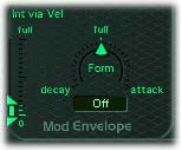
Use the ES1 modulation envelope
The modulation envelope can directly modulate the parameter chosen in the router. It
determines the time it takes for the modulation to fade in or fade out. At its center position (click
Full), modulation intensity is static—no fade-in or fade-out occurs. When set to its full value,
modulation intensity is at a constant level.
The modulation envelope allows you to set either a percussive type of decay envelope by
choosing low values or an attack type of envelope by choosing high values.
Modulation envelope parameters
•Form slider and eld: Drag to set a fade-in (attack) or fade-out (decay) time for the modulation.
When set to the full position, the modulation envelope is turned o.
•Int via Vel sliders: The top arrow sets the upper limit for the modulation envelope—for the
hardest keystrike (velocity = 127). The bottom arrow sets the lower limit—for the softest
keystrike (velocity = 1). The green bar between the arrows displays the impact of velocity
sensitivity on the intensity of the modulation envelope.
You can simultaneously adjust the modulation range and intensity by dragging the green
bar, thus moving both arrows at once. Note that as you do so, the arrows retain their relative
distance from each other.
Modulate a parameter with velocity
1 Select a modulation target, such as Pulse Width, from the right column of the router.
2 Set the Form slider to full, and adjust the Int via Vel parameter as needed.
This results in a velocity-sensitive modulation of the oscillator pulse width.
More interestingly, you can directly control the LFO level if you click the LFO Amp(litude) button
in the right column of the router.
Fade the LFO modulation in or out
mTo fade in the LFO modulation: drag the Form slider to a positive value—toward attack. The higher
the value, the longer it takes for you to hear the modulation.
mTo fade out the LFO modulation: drag the Form slider to a negative value—toward decay. The
lower the value—closer to decay—the shorter the fade-out time is.
LFO control with envelopes is most often used for delayed vibrato, a technique many
instrumentalists and singers employ to intonate longer notes.
Set up a delayed vibrato
1 Drag the Form slider to the right—toward attack.
2 Select Pitch as the LFO target in the left column of the router.
3 Use the Wave knob to select the triangular wave as the LFO waveform.
4 Drag the Rate eld to an LFO rate of about 5 Hz.
5 Drag the upper Int via Wheel arrow to a low value, and the lower arrow to 0.

Chapter 2 ES1 33
ES1 MIDI controllers
ES1 responds to the following MIDI continuous controller numbers (CC).
Controller number Parameter name
12 Oscillator pitch buttons
13 Oscillator waveform
14 Mix slider
15 Waveform of sub-oscillator
16 Drive slider
17 Cuto slider
18 Resonance slider
19 Slope buttons
20 ADSR via Vel (lower slider)
21 ADSR via Vel (upper slider)
22 Attack slider
23 Decay slider
24 Sustain slider
25 Release slider
26 Key slider
27 Amplier Envelope Selector buttons
28 Level via Velocity (lower slider)
29 Level via Velocity (upper slider)
30 Chorus parameter
31 Modulation envelope target
102 Modulation envelope form slider
103 Modulation envelope: Int via Vel parameter
(lower slider)
104 Modulation envelope: Int via Vel parameter
(upper slider)
105 LFO rate
106 LFO waveform
107 LFO modulation target
108 LFO: Int via Whl (lower slider)
109 LFO: Int via Whl (upper slider)
110 Glide slider
111 Tune parameter
112 Analog parameter
113 Bender Range parameter
114 Out Level parameter
115 Voices parameter
34
ES2 overview
ES2 combines subtractive synthesis with elements of FM and wavetable synthesis to help
you generate an extraordinary variety of sounds. This makes it the perfect choice for creating
powerful pads, evolving textures, rich basses, or synthetic brass.
If you’re new to synthesizers, see Synthesizer basics overview on page 472, which introduces you
to the fundamentals and terminology of dierent synthesis systems.
The three oscillators of the ES2 provide classic analog synthesizer waveforms (including noise)
and 100 single-cycle waveforms, known as Digiwaves. This raw material forms the basis for
sounds that range from fat analog to harsh digital sounds, or hybrids of the two. You can also
cross-modulate oscillators, making it easy to create FM-style sounds. Further options include the
ability to synchronize and ring-modulate the oscillators or to mix a sine wave directly into the
output stage, to thicken the sound.
ES2 features a exible modulation router that oers up to ten simultaneous (user-dened)
modulation routings. Further modulation options include the unique Planar Pad—which
provides control of two parameters on a two-dimensional grid. The Planar Pad itself can be
controlled by the sophisticated Vector Envelope. This is a multipoint, loop-capable envelope that
makes it easy to create complex, evolving sounds.
Lastly, Distortion, Chorus, Phaser, and Flanger eects are built into the ES2.
If you want to begin experimenting right away, there are a number of settings to try. There
are also two tutorials that provide tips and information, and invite you to explore the ES2. See
ES2 sound design from scratch overview on page 95 and ES2 sound design with templates on
page 106.
Note: You will nd tasks that cover the use of parameters as modulation targets or sources
throughout these pages. This underlines one of ES2’s greatest strengths—namely, the vast
modulation possibilities it oers. Follow the steps in these tasks to create expressive, evolving
sounds. See ES2 modulation overview on page 59.
ES2 3
Chapter 3 ES2 35
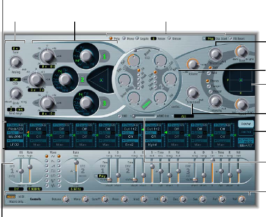
ES2 interface
ES2’s graphical interface is divided into the following main areas.
Modulation controls and
parameters
Macro Sound
parameters
Random
parameters
Click here to
display the Vector
Envelope.
Amplifier
parameters
Planar Pad
Filter section
Effect section
Global parameters
Oscillator section
Global
parameters
Modulation router
•Oscillator section: The oscillator parameters are shown in the upper-left area of the
ES2 interface. The Triangle is used to set the mix relationships between the three oscillators.
See ES2 oscillator parameters overview on page 37.
•Global parameters: A number of related global parameters that directly inuence the overall
output of the ES2, such as Tune, are found to the left of the oscillators, and above the amplier
and lter parameters. See Global parameters overview on page 47.
•Filter section: The circular area houses the lter section, including the Drive and Filter
FM parameters. See ES2 lter overview on page 50.
•Amplier parameters: The area at the top right contains the output parameters, where you
can set the overall volume of the ES2, and add a sine signal at the output stage. See Use ES2’s
dynamic stage on page 58.
•Modulation router or Vector Envelope: The dark strip across the center of the ES2 interface is
shared by the modulation router and the Vector Envelope. Use the buttons at the right end of
this section to switch between the two.
•The router links modulation sources, such as the envelopes and other parameters shown in
the lower portion of the interface, to modulation targets, such as the oscillators and lters.
See Use the modulation router on page 60.
•The Vector Envelope is a exible, powerful envelope generator that provides extensive
control over your sound. See Use the Vector Envelope on page 70.
Chapter 3 ES2 36
•Modulation controls and parameters: The area immediately below the router is where you can
assign and adjust the modulation generator parameters (such as LFO and envelope controls).
See ES2 modulation overview on page 59.
•Planar Pad: The square area at the top right is a two-dimensional controller known as the
Planar Pad. The Planar Pad facilitates the simultaneous manipulation of two assignable
parameters, and can be controlled with the mouse, another controller, or the Vector Envelope.
See Use the Planar Pad on page 77.
•Eect section: The built-in eect-processing options are found to the right of the output
parameters. See ES2 integrated eects processor on page 88.
•Macro and MIDI controller parameters: The area shown on the thin, gray strip at the bottom can
display either Macro parameters or MIDI controller assignments. The preassigned macro sound
parameters are perfect for quick tweaks to the ES2’s sound (and that of ES2-based GarageBand
instruments). You can reassign MIDI control numbers for these parameters. See ES2 macro and
controller assignment overview on page 90.

Chapter 3 ES2 37
ES2 sound sources
ES2 oscillator parameters overview
ES2 oscillators are used to generate one or more waveforms. This signal is then sent to other
portions of the synthesizer engine for shaping, processing, or manipulation.
•Oscillators 2 and 3 are almost identical to each other, but they dier from oscillator 1.
•Oscillator 1 can be frequency modulated by oscillator 2, for FM synthesis sounds.
•Oscillators 2 and 3 can be synchronized to, or ring modulated with, oscillator 1. They also have
rectangular waves with either user-dened xed pulse widths or pulse width modulation
(PWM) features.
•You can use the modulation router to simultaneously change the pulse widths of rectangular
waves generated by oscillator 1 and the synchronized and ring-modulated rectangular waves
of oscillators 2 and 3.
(Fine) Frequency
value field
Wave knob
Oscillator Mix (Triangle)
Oscillator on/off button
(Coarse) Frequency knob
Oscillator parameters
•Oscillator on/o buttons: The number to the right of each oscillator activates or deactivates
each oscillator independently. A green numeric button indicates an active oscillator. A gray
numeric button denotes an inactive oscillator. Deactivating an oscillator saves computer
processing power.
•Wave knobs: Rotate to choose the waveform that an oscillator generates. The waveform is
responsible for the basic tonal color. See ES2 basic oscillator waveforms on page 38.
•(Coarse) Frequency knobs: Rotate to set the oscillator’s pitch, in semitone steps, over a range
of ±3 octaves. Because an octave consists of 12 semitones, the ±12, 24, and 36 settings
represent octaves.
•(Fine) Frequency value elds: Fine-tune the oscillator frequency (pitch). The left numbers show
the semitone s setting, and the right numbers show the cent c setting (1 cent = 1/100th
semitone). For example, an oscillator with the value 12 s 30 c sounds an octave (12 semitones)
and 30 cents higher than an oscillator with the value 0 s 0 c. Drag vertically to adjust
each value.
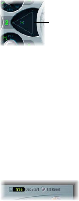
•Oscillator Mix (Triangle): Move the pointer in the Triangle to cross-fade (set the level
relationships) between the three oscillators. See Balance ES2 oscillator levels on page 45.

Chapter 3 ES2 38
ES2 basic oscillator waveforms
All ES2 oscillators output a number of standard waveforms—sine, pulse, rectangular, sawtooth,
and triangular waves—or, alternately, any of 100 Digiwaves (see Use ES2 Digiwaves on page 42).
The following table covers the basic waveforms:
Waveform Basic tone Comments
Pulse/Rectangular Nasal sounding Great for reed instruments, synth
blips, and basses
Square Hollow and woody sounding Useful for basses, clarinets,
and oboes. The pulse width
of (oscillator 2 and 3) square
waveforms can be smoothly scaled
between 50% and the thinnest of
pulses.
Sawtooth Warm and even Useful for strings, pads, bass, and
brass sounds
Triangle Sweet sounding, softer than
sawtooth
Useful for utes and pad sounds
Sine A pure tone The sine wave of oscillator 1
can be frequency modulated
by oscillator 2. This kind of
modulation forms the basis of
FM synthesis (see Use frequency
modulation in ES2 on page 40).
Oscillators 2 and 3 also oer the selection of:
•A rectangular wave, synchronized to oscillator 1
•A sawtooth wave, synchronized to oscillator 1
•A ring modulator, which is fed by the output of oscillator 1 and a square wave from oscillator 2
•Colored noise for oscillator 3. See Use the ES2 noise generator on page 42.
Oscillator synchronization and ring modulation allow for the creation of very complex and
exible harmonic spectra. The principles behind oscillator synchronization are described in
Synchronize ES2 oscillators on page 46. Ring modulation principles are described in Use ring
modulation in ES2 on page 41.
Chapter 3 ES2 39
Use pulse width modulation in ES2
You can alter the tonal color of rectangular waveforms by scaling the width of waveform pulses
to any value. This is known as pulse width modulation.
ES2 pulse width modulation features are extensive. For example, if rectangular waves are chosen
for all oscillators, you can simultaneously modulate the pulse width of oscillator 1 and the
synchronized pulse waves of oscillator 2 (or the square wave of oscillator 2’s ring modulator) and
oscillator 3.
Set a basic pulse width in oscillator 2 or 3
mDrag the waveform rotary control that surrounds the Wave knob (see the highlighted area in the
image above).
Only oscillators 2 and 3 allow you to dene a base (default) pulse width, prior to any pulse
width modulation.
Set up a pulse width modulation (of oscillator 1) in the router
1 Choose a rectangle wave for oscillator 1.
2 In the router, choose Osc1Wave as the target, and LFO1 as the source.
3 Adjust the modulation amount slider (try a value of 0.12).
4 Choose a sine wave for LFO 1.
5 Adjust the LFO 1 Rate (around 0.160 Hz for a slow sweep).
Chapter 3 ES2 40
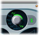
Use frequency modulation in ES2
The principle of frequency modulation (FM) synthesis was developed in the late 1960s and early
1970s by John Chowning. It was popularized by Yamaha’s range of DX synthesizers in the 1980s.
Although the ES2 can’t be compared with the DX series in the discipline of pure FM synthesis, it
can achieve some of the signature sounds of these instruments.
In pure FM synthesis, the frequency of one signal generator, or oscillator, is altered (modulated)
by another signal generator. Positive values from the second generator increase the frequency
of the rst generator. Negative values decrease the frequency. In a synthesizer, this type of
modulation takes place in the audible range. Depending on the design of the instrument, you
can hear the signals of either the rst oscillator alone (being modulated by the other oscillator),
or both oscillators. The interaction between the two generators alters the waveform signal of the
rst oscillator and introduces a number of new harmonics. This harmonic spectrum can then be
used as the source signal for further sound processing, such as ltering, envelope control, and so
on. See Frequency modulation (FM) synthesis on page 493 for further information.
In ES2, the frequency of oscillator 1 (with a sine wave chosen—11 o’clock position for the Wave
knob) can be modulated by the output signal of oscillator 2.
•When oscillator 2 outputs a positive signal, the frequency of oscillator 1 increases.
•When oscillator 2 outputs a negative signal, the frequency of oscillator 1 decreases.
The net eect of speeding up or slowing down the frequency of oscillator 1 in each waveform
cycle is a distortion of the basic wave shape. This waveform distortion also has the side benet of
introducing a number of new, audible harmonics.
Important: The impact of any frequency modulations you perform depends on both the
frequency ratio and the modulation intensity of the two oscillators.
The “pure” FM synthesis method uses a sine wave for both the rst and second signal generator
(both oscillator 1 and 2 would be limited to generating a sine wave in ES2 if you stuck with this
approach). ES2, however, provides 100 Digiwaves and countless combinations of modulation
intensities and frequency ratios that can be used for either oscillator. This provides a vast pool of
harmonic spectra and tonal colors for you to experiment with.
Tip: The type of modulation that occurs can vary signicantly when dierent waveforms are
chosen for oscillator 2—the modulating oscillator—in particular.
Set the frequency ratio and adjust the modulation intensity
1 Adjust the Frequency (coarse and ne tune) parameter values of one, or both, oscillators.
2 Click (or drag) in the control range between the Sine and FM icons around the oscillator 1 Wave
knob.
This determines the amount, or intensity, of frequency modulation.

Chapter 3 ES2 41
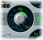
Use ring modulation in ES2
Ring modulation is a powerful tool for the creation of inharmonic, metallic, bell-like sounds. The
spectra resulting from its use are inharmonic at almost every frequency ratio. The ring modulator
is a device that dates back to the early days of the synthesizer.
A ring modulator has two inputs. At the output you hear both the sum and dierence
frequencies of the input signals. If you ring modulate a sine oscillation of 200 Hz with a sine
oscillation of 500 Hz, the output signal of the ring modulator consists of a 700 Hz (sum) and a
300 Hz (dierence) signal. Negative frequencies result in a change to the phase polarity of output
signals.
Tip: Use sawtooth and rectangular (pulse width modulated) input signals from oscillators 1 and
2, respectively, to create a much more complex output signal. The use of these harmonically rich
waveforms results in a number of extra sidebands becoming audible.
Create a ring-modulated sound
1 Set the oscillator 2 Wave knob to the Ring setting.
2 Experiment with dierent Frequency (main and ne tune) values for one, or both, oscillators.
The oscillator 2 ring modulator is fed with the output signal of oscillator 1 and a square wave,
generated by oscillator 2 itself. The pulse width of this square wave can be modulated (see Use
pulse width modulation in ES2 on page 39).
Chapter 3 ES2 42
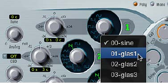
Use ES2 Digiwaves
In addition to the basic synthesizer waveforms, all ES2 oscillators provide 100 additional
waveforms, called Digiwaves. These are very short samples of the attack transients of various
sounds and instruments.
Choose a Digiwave
mSet the Wave knob to Sine (6 o’clock position), then do one of the following:
•Control-click or right-click the Sine label, then choose a waveform from the pop-up menu.
•Drag the Sine label vertically.
•To select the Digiwave numerically, Shift-click the Sine label, then type a value.
Use the ES2 noise generator
The sonic palette of oscillator 3 is bolstered by the inclusion of a noise generator, which can be
activated by choosing the noise waveform. By default, oscillator 3’s noise generator generates
white noise.
White noise is dened as a signal that consists of all frequencies (an innite number) sounding
simultaneously, at the same intensity, in a given frequency band. The width of the frequency
band is measured in Hertz. Sonically, white noise falls between the sound of the consonant “F”
and breaking waves (surf). White noise is useful for synthesizing wind and seashore noises, or
electronic snare drum sounds.
You can also modulate the tonal color of the noise signal in real time—without using the main
lters of the ES2—by modulating the waveform of oscillator 3.
Change the noise color
1 Set up a modulation routing as follows: modulation target Osc3Wave, source ModWhl. The
modulation amount slider behaves somewhat dierently with this routing, essentially acting like
a lter.
2 Use negative modulation amount values (not −1.000) to set a descending lter slope that
roughly equates to 6 dB/octave. The sound becomes darker (red noise) as you adjust the mod
wheel downwards.
3 To tune this pseudo lter down to 18 Hz, set the modulation amount to −1.000. When Osc3Wave
is modulated positively, the noise becomes brighter (blue noise).
4 If you choose a modulation amount value of +1.000 for the Osc3Wave modulation target, the
lter cuto frequency is set to 18 kHz.

Chapter 3 ES2 43
ES2 emulation of detuned analog oscillators
The Analog parameter randomly alters the pitch of each note and the lter cuto frequency.
•Low Analog values can add a subtle richness to the sound.
•Medium Analog values simulate the tuning instabilities of analog synthesizer circuitry, which
can be useful in achieving that much sought-after “warmth” of analog hardware synthesizers.
•High Analog values result in signicant pitch instability, which can sound truly out of tune—
but this may be perfect for your needs.
Rotate the Analog knob to randomly alter the pitch of each note, and the lter cuto frequency.
Much like polyphonic analog synthesizers, all three oscillators maintain their specic frequency
deviation from each other, but the pitches of all three oscillators are randomly detuned by
the same Analog amount. For example, if the Analog detuning is set to around 20%, all three
oscillators (if used) randomly drifts by 20%.
Note: If ES2 is set to Mono or Legato keyboard mode, the Analog parameter is eective only
when Unison is turned on. In this situation, Analog sets the amount of detuning between the
stacked (unison) voices. If the Voices parameter is set to 1 and/or Unison is not active, the Analog
parameter has no eect. For more information about these parameters, see Set the ES2 keyboard
mode on page 48.
Chapter 3 ES2 44
Stretch tuning in ES2
The (coarse) Frequency knob of each oscillator enables you to tune oscillators 1, 2, and 3 in
semitones or octaves. The (ne tune) Frequency parameter enables you to ne-tune each
oscillator in cents (1/100th of a semitone). Precise detuning between oscillators can result in
beats, or phasing, between the oscillator frequencies. The higher the played frequency/pitch,
the faster the phasing beats. High notes, therefore, may seem to be somewhat out of tune in
comparison with lower notes.
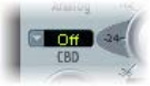
CBD (Constant Beat Detuning) can be used as a corrective tool to even out the beating between
oscillators, or it can be used as a creative tool to emulate stretch tuning. The latter can be
particularly important when you use an ES2 sound alongside an acoustic piano recording. This is
because acoustic pianos are intentionally tuned “out-of-tune” (from equal temperament). This is
known as stretch tuning, and results in the upper and lower keyboard ranges being slightly out of
tune with the center octaves but harmonically “in-tune” with each other.
Choose a CBD value to detune the harmonics of low note frequencies in a ratio proportionate
with the fundamental tone of the upper note frequencies.
CBD oers ve values: o, 25%, 50%, 75%, and 100%. If you choose 100%, the phasing beats are
almost constant across the entire keyboard range. This value may, however, be too high, because
the lower notes might be overly detuned at the point where the phasing of the higher notes
feels right. Try lower CBD values in cases where the bass notes are a little too far out of tune with
the upper keyboard range.
The reference pitch for CBD is C3 (middle C): its (de)tuning is constant, regardless of the chosen
CBD value.
Chapter 3 ES2 45
Balance ES2 oscillator levels
The position of the pointer in the Triangle is described by two parameters—x and y
coordinates—which are used when automating the oscillator mix. These parameters, called
OscLevelX and OscLevelY, are available as targets in the router.
Drag the pointer in the Triangle to cross-fade—set the level relationships—between the three
oscillators. This is self-evident in use. If you move the pointer along one of the Triangle’s sides, it
cross-fades between the two closest oscillators, and the third oscillator is muted.
Click or drag in the
Triangle to change the
level balance between
the oscillators.
The position of the pointer (x and y coordinates) in the Triangle can also be controlled with
the Vector Envelope. Because the Vector Envelope features a loop function, it can be used as a
pseudo-LFO with a programmable waveform. For more information about this feature, see Use
the Vector Envelope on page 70.
Modulate triangle coordinates with the modulation wheel
1 Set up a modulation routing as follows: modulation target OscLevelX, source ModWhl. Adjust
the intensity.
2 Set up a second modulation routing as follows: modulation target OscLevelY, source ModWhl.
Adjust the intensity. You can choose other sources for these targets.
ES2 oscillator start points
The oscillators can run freely or can begin at the same phase position of their respective
waveform cycles each time a note is struck.
Choose free, soft, or hard from the Osc(illator) Start pop-up menu.
•Free: The initial oscillator phase start point is random for each played note. This adds life to the
sound. The downside is that the output level may dier each time a note is played, making
the attack phase sound less punchy—even if the performance is identical each time—such
as when the note is triggered by a MIDI region. This setting is useful when you are emulating
sounds typical of hardware analog synthesizers.
•Soft: The initial oscillator phase starts at a zero crossing for each played note. This mimics the
sonic character (and precision) typical of digital synthesizers.
•Hard: The initial oscillator phase starts at the highest level in the waveform cycle for each
played note. The extra punch that this setting can provide is audible only if the ENV3 Attack
Time parameter is set to a low value—a very fast attack, in other words. This setting is highly
recommended for electronic percussion and hard basses.
Note: Osc Start soft and hard result in a constant output level of the initial oscillator phase every
time the sound is played back.
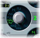
Chapter 3 ES2 46
Synchronize ES2 oscillators
Typical oscillator sync sounds tend toward the aggressive, screaming leads that synthesizer
manufacturers like to talk about. The rectangular and sawtooth waveforms of oscillators 2
and 3 feature a Sync option. When this parameter is turned on, the phase of oscillator 2 or 3 is
synchronized with oscillator 1.
Every time oscillator 1 starts a new oscillation phase, the synchronized oscillator (oscillator 2
or 3) is also forced to restart its phase from the beginning. Between the waveform cycles of
oscillator 1, the waveform cycles of the synchronized oscillators run freely.
You can achieve interesting synchronized oscillator sounds by modulating the frequency of
the synchronized oscillator with an envelope generator. This constantly changes the number of
phases within a section of the synchronization cycle, resulting in corresponding changes to the
frequency spectrum.
Modulate the synchronized oscillator frequency with an envelope
1 Set the oscillator 2 Wave knob to Sync.
2 Set up a modulation routing as follows: modulation target Pitch2, source Env2.
3 Adjust the settings of Envelope 2.
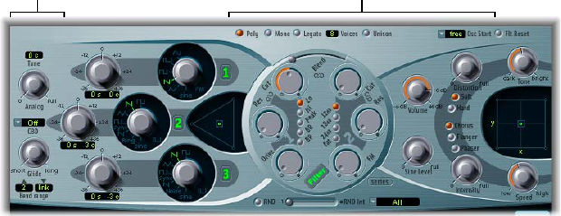
Chapter 3 ES2 47
ES2 global parameters
Global parameters overview
The ES2 global parameters aect the overall instrument sound produced by ES2. You can nd
global parameters to the left of the oscillators and above the lter and output sections.
Global parameters
Global parameters
Global parameters
•Keyboard Mode buttons: Switch ES2 between polyphonic, monophonic, and legato behaviors.
See Set the ES2 keyboard mode on page 48.
•Unison button: Click to turn unison mode on or o. See Use unison and voices in ES2 on
page 48.
•Voices eld: Drag to set the maximum number of notes that can be played simultaneously.
•Glide knob: Rotate to set the time it takes for the pitch of a played note to slide to the pitch of
the following played note. See Set the ES2 glide time on page 49.
•Bend Range elds: Drag to dene the upward and downward pitch bend range. See Set the ES2
pitch bend range on page 49.
•Tune eld: Drag to set the overall instrument pitch in cents. 100 cents equals a semitone step.
At a value of 0 c (zero cents), the central A key is tuned to 440 Hz, or concert pitch.
•Analog knob: Rotate to randomly alter the pitch of each note and the lter cuto frequency.
See ES2 emulation of detuned analog oscillators on page 43).
•Constant Beat Detuning (CBD) pop-up menu: Choose a CBD value to detune the harmonics of
low note frequencies in a ratio proportionate with the fundamental tone of the upper note
frequencies. See Stretch tuning in ES2 on page 44.
•Osc(illator) Start pop-up menu: Choose free, soft, or hard from the Osc(illator) Start pop-up
menu. See ES2 oscillator start points on page 45.

Chapter 3 ES2 48
Set the ES2 keyboard mode
A polyphonic instrument, such as an organ or a piano, allows several notes to be played
simultaneously. Many older analog synthesizers are monophonic, which means that only one
note can be played at a time, much like a brass or reed instrument. This shouldn’t be viewed as a
disadvantage; instead, it allows playing styles that are not possible with polyphonic instruments.
Change the keyboard mode
mClick the Poly, Mono, or Legato button.
•In Mono mode, staccato playing retriggers the envelope generators every time a new note
is played. If you play in a legato style (play a new key while holding another), the envelope
generators are triggered only for the rst note you play legato, then they continue their curve
until you release the last legato played key.
•Legato mode is also monophonic, but with one dierence: the envelope generators are
retriggered only if you play staccato—releasing each key before playing a new key. If you play
in a legato style, envelopes are not retriggered.
Note: On several monophonic synthesizers, the behavior in Legato mode is referred to as single
trigger, while Mono mode is referred to as multi trigger.
Use unison and voices in ES2
Unison mode in polyphonic analog synthesizers is typically monophonic, with all voices playing
simultaneously when a single note is struck. Because the voices of an analog synthesizer are
never perfectly in tune, the result is an extremely fat chorus eect with great sonic depth.
Use monophonic unison mode
1 Click the Mono or Legato button, depending on the keyboard mode you want to use. See Set the
ES2 keyboard mode.
2 Click the Unison button.
•The intensity of the unison eect depends on the number chosen in the Voices parameter
eld. Increase the Voices value for a fatter sound. See Global parameters overview.
•The intensity of detuning (voice deviation) is set with the Analog parameter. See ES2
emulation of detuned analog oscillators.
Use polyphonic unison mode
mClick the Poly and Unison buttons.
In poly/unison mode, each played note is eectively doubled—or, more correctly, the polyphony
value chosen with the Voices parameter is halved. These two voices are heard when you trigger
the note. Poly/unison has the same eect as setting the ES2 to mono/unison (Voices = 2), but
you can play polyphonically.
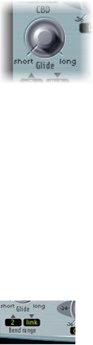
Chapter 3 ES2 49
Set the ES2 glide time
The Glide parameter (also known as portamento) sets the time it takes for the pitch of one played
note to travel to the pitch of another played note.
Make portamento active
mRotate the Glide knob.
Glide behavior is dependent on the chosen keyboard mode. See Set the ES2 keyboard mode.
•If the keyboard mode is set to Poly or Mono, and Glide is set to a value other than 0,
portamento is active.
•If Legato is chosen, and Glide is set to a value other than 0, you need to play legato (press a
new key while holding the old one) to activate portamento. If you don’t play in a legato style,
portamento won’t work. This behavior is also known as ngered portamento.
Set the ES2 pitch bend range
The Bend range elds determine the range for pitch bend modulation, typically performed with
your keyboard’s pitch bend wheel.
Set independent upward and downward bend ranges
mDrag in either eld to set a bend range.
Set an identical upward and downward bend range
1 Set the upward Bend range eld to Link mode.
This locks the upward and downward bend ranges, making them identical.
2 Set a downward Bend range value.
This is mirrored in the upward Bend range eld.
Note: A downward bend of 4 semitones results in a combined bend range of 8 semitones—9 if
you include the standard pitch, or “no bend” position.
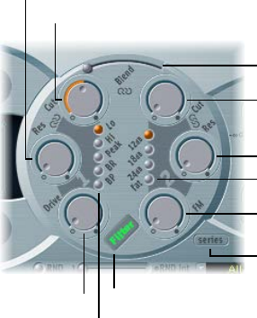
Chapter 3 ES2 50
ES2 lter parameters
ES2 lter overview
ES2 features two discrete, and dierent, lters.
•Filter 1 can operate as a lowpass, highpass, bandpass, band reject, or peak lter.
•Filter 2 is a lowpass lter that oers variable slopes (measured in dB/octave).
Filter button
Filter 1 Mode
Filter Drive
Click here to choose a
parallel or series filter
configuration.
Filter FM
Filter 2 Slope
Filter 2 Resonance
Filter 2 Cutoff
Filter Blend
Filter 1 Cutoff
Filter 1 Resonance
Filter parameters
•Filter button: Turns the entire lter section on or o. Deactivating the lter section makes it
easier to hear adjustments to other sound parameters, because the lters always heavily aect
the sound. Disabling the lters also reduces processor load.
•Filter Conguration button: Switches between a parallel or series lter conguration. See ES2
lter conguration on page 51.
•Filter Blend slider: Sets the balance between Filter 1 and Filter 2. See Cross-fade between ES2
lters on page 51.
•Filter 1 Mode buttons: Switch Filter 1 between lowpass, highpass, bandpass, band reject, or peak
lter types. See ES2 Filter 1 modes on page 53.
•Filter 2 Slope buttons: Switch Filter 2 between dierent slopes. See ES2 Filter 2 slopes on
page 53.
•Cuto and Resonance: Rotate the Cuto and Resonance knobs to determine the cuto
frequency and resonance behavior of each lter. See Filter cuto and resonance overview on
page 54.
•Filter Drive knob: Rotate to overdrive the lter, which aects each voice independently. See
Overdrive ES2 lters on page 56.
•Filter FM knob: Rotate to set the amount of Filter 2 cuto frequency modulation with the
oscillator 1 frequency. See Modulate ES2’s Filter 2 Frequency on page 57.
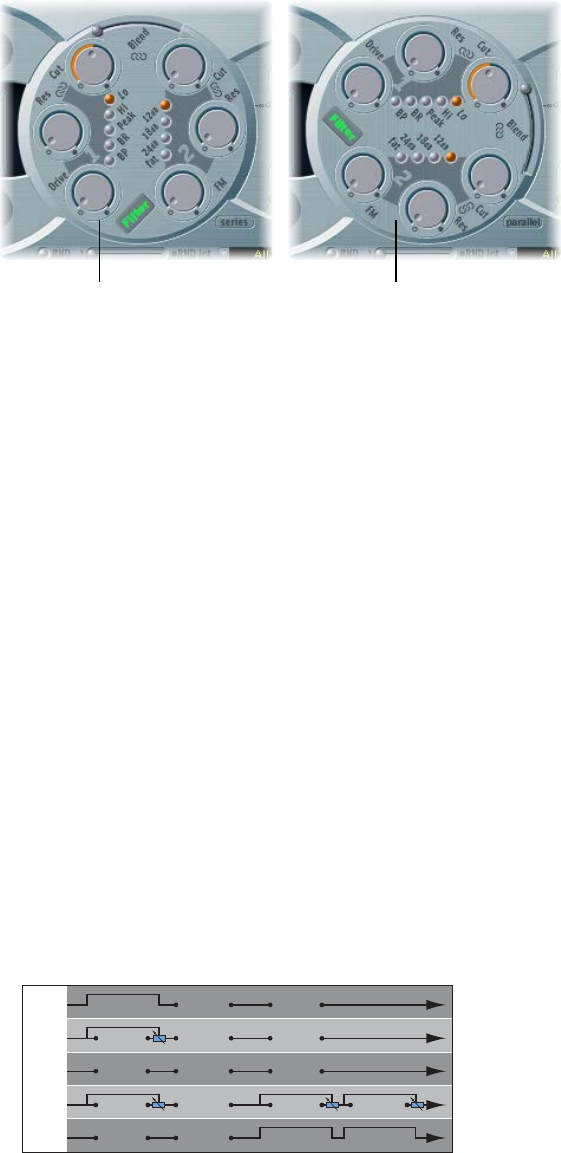
Chapter 3 ES2 51
ES2 lter conguration
The Filter Conguration button lets you switch between a parallel and series lter routing. When
either is chosen, the entire circular lter element rotates, and the positions and direction of the
lter controls clearly indicate the signal ow. The button name also changes in each mode.
Series filter signal flow Parallel filter signal flow
In the gure to the left, the lters are cabled in series. This means that the signal of all oscillators
(combined at the Oscillator Mix Triangle) passes through the rst lter, then this ltered signal
passes through Filter 2, if Filter Blend is set to 0, the middle position. The output signal of Filter 2
is then sent to the input of the dynamic stage (Amplier section).
In the gure to the right, the lters are cabled in parallel. If Filter Blend is set to 0, you’ll hear a
50/50 mix of the source signal, routed via Filter 1 and Filter 2. The output signals of the two lters
are then sent to the input of the dynamic stage. See Cross-fade between ES2 lters.
Cross-fade between ES2 lters
Filter Blend can have a signicant eect on the ES2 signal ow. Regardless of whether parallel
or series lter congurations are chosen, a Filter Blend setting of −1 results in only Filter 1 being
audible. A Filter Blend setting of +1 limits audibility to Filter 2. The gures illustrate the signal
ow between the Oscillator Mix stage (the Triangle) and the dynamic stage (the Amplier). The
signal ow through the lters and the lter overdrive circuit (the Drive parameter) are dependent
on the Filter Blend setting.
•Filter Blend: Series lter conguration information
•Use positive values for Filter Blend to partially bypass Filter 1.
•Use negative values for Filter Blend to partially bypass Filter 2.
•When zero or positive Filter Blend values are used, there is only one overdrive circuit for
both lters.
•Use of negative Filter Blend values introduces another overdrive circuit, which distorts the
output signal of the oscillator mix stage before it is fed into the rst lter.
•If Drive is set to 0, no distortion occurs.
Filter 1
Filter 1
Filter 1
Drive
Drive
Drive
Drive
Drive
Filter 1
Filter 1
Filter 2
Filter 2
Filter 2
Drive
Drive
Filter 2
Filter 2
+1:
–0,5:
+0,5:
–1:
0:
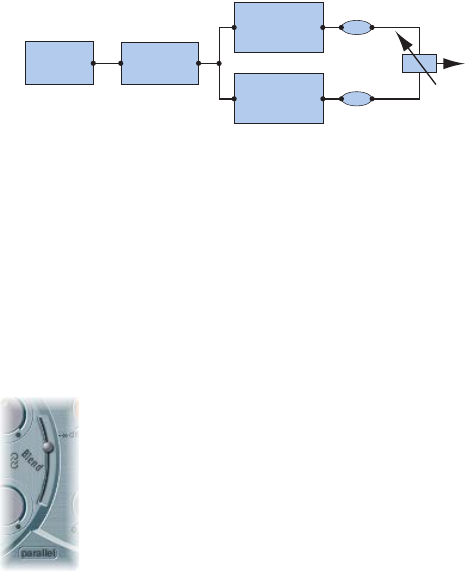
Chapter 3 ES2 52
•Filter Blend: Parallel lter conguration information
In a parallel conguration, the overdrive/distortion circuit—the Drive parameter—is always
wired after the oscillator mix stage—the Triangle—and before the lters. The lters receive
a mono input signal from the output of the overdrive circuit. The outputs of both lters are
mixed to mono via Filter Blend.
Mix
Filter 1
Drive
Filter 2
The Filter Blend parameter is available as a modulation target in the router. You can use manual
control sources, such as the modulation wheel, to change the lter blend; but the Filter Blend
target can also be used creatively, to rapidly switch or smoothly fade between the two lters.
You can also use velocity, or a combination of the Vector Envelope and Planar Pad as sources.
The latter allows for interesting lter control possibilities that evolve independently, or alongside
oscillator parameters that are also being controlled with the Vector Envelope.
Cross-fade between lters
mDrag the Filter Blend slider to cross-fade between the two lters when cabled in parallel.
•If Filter Blend is set to the top position, you only hear the eect of Filter 1.
•If Filter Blend is set to its lowest position, you only hear the eect of Filter 2.
•In between these positions, the lters are cross-faded. You hear the eect of both lters.
You can also cross-fade the lters when they are cabled in series. In this situation, the
distortion—controlled by the Drive parameter—also needs to be considered, as this can be
positioned either before or in between the lters, depending on the Filter Blend setting you
choose.
Modulate Filter Blend with an LFO
1 Set up a modulation routing as follows: modulation target FltBlend, source LFO2.
2 Adjust the settings of LFO 2.

Chapter 3 ES2 53
ES2 Filter 1 modes
Filter 1 can operate in several modes, allowing specic frequency bands to be ltered (cut away)
or emphasized.
Click one of the following lter mode buttons for Filter 1:
•Lo (lowpass): Allows frequencies that fall below the cuto frequency to pass. The slope of
Filter 1 is xed at 12 dB/octave.
•Hi (highpass): Allows frequencies above the cuto frequency to pass. The slope of Filter 1 is
xed at 12 dB/octave.
•Peak: Filter 1 works as a peak lter. This allows the level in a frequency band to be increased.
The center of the frequency band is determined by the Cuto parameter. The width of the
band is controlled by the Resonance parameter.
•BR (band reject): The frequency band directly surrounding the cuto frequency is rejected, but
frequencies outside this band can pass. The Resonance parameter controls the width of the
rejected frequency band.
•BP (bandpass): The frequency band directly surrounding the cuto frequency is allowed
to pass. All other frequencies are cut. The Resonance parameter controls the width of the
frequency band. The bandpass lter is a two-pole lter with a slope of 6 dB/octave on each
side of the band’s center frequency.
ES2 Filter 2 slopes
Most lters do not completely suppress the portion of the signal that falls outside the frequency
range dened by the Cuto parameter. The slope, or curve, chosen for Filter 2 expresses the
amount of rejection below the cuto frequency in decibels per octave.
Slope buttons: Click any button to choose a Filter 2 slope: 12 dB, 18 dB, and 24 dB. The steeper the
slope, the more severe the eect on signal levels below the cuto frequency.
Fat button: Click the Fat button for 24 dB per octave of rejection. Fat mode has a built-in
compensation circuit that retains the sound’s bottom end. By comparison, the standard 24 dB
setting tends to make lower end sounds less rich.
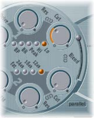
Chapter 3 ES2 54
ES2 lter cuto and resonance
Filter cuto and resonance overview
In every lowpass lter (ES2: Lo mode for Filter 1; Filter 2 is a lowpass lter), all frequency
portions above the cuto frequency are suppressed, or cut o, hence the name. If you’re new to
synthesizers and the concepts behind lters, see Synthesizer basics overview on page 472.
Cuto and resonance parameters
•Cuto Frequency knob: Rotate to control the brilliance of the signal.
•In a lowpass lter, the higher the cuto frequency is set, the higher the frequencies of signals
that are allowed to pass.
•In a highpass lter, the cuto frequency determines the point where lower frequencies are
suppressed and only upper frequencies are allowed to pass.
•In a bandpass/band rejection lter, the cuto frequency determines the center frequency for
the bandpass or band rejection lter.
•Resonance knob: Rotate to emphasize or suppress portions of the signal above or below the
dened cuto frequency.
•In a lowpass lter, Resonance emphasizes or suppresses signals below the cuto frequency.
•In a highpass lter, Resonance emphasizes or suppresses signals above the cuto frequency.
•In bandpass/band rejection lters, resonance emphasizes or suppresses the portions of
the signal—the frequency band—that surround the dened frequency, set with the Cuto
Frequency parameter.
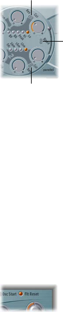
Chapter 3 ES2 55
Control two lter parameters simultaneously
The ability to change the Cuto and Resonance controls at the same time is essential for creating
expressive synthesizer sounds.
mDrag one of the three chain symbols in the ES2 lter section.
Click here to
simultaneously adjust
the cutoff of both Filter 1
and Filter 2.
Click here to
simultaneously adjust
the cutoff and
resonance of Filter 2.
Click here to
simultaneously adjust
the cutoff and
resonance of Filter 1.
•The chain between Cut and Res of Filter 1 controls both the resonance (drag horizontally) and
cuto frequency (drag vertically) simultaneously.
•The chain between Cut and Res of Filter 2 controls both the resonance (drag horizontally) and
cuto frequency (drag vertically) simultaneously.
•The chain between Filter 1 Cut and Filter 2 Cut controls the cuto frequency of Filter 1 (drag
vertically) and Filter 2 (drag horizontally) simultaneously.
Force ES2 lters to self-oscillate
If you increase the lter Resonance parameter to higher values, the lter begins to internally
feed back and, as a consequence, begins to self-oscillate. This results in a sine oscillation—a sine
wave—that is actually audible.
To start this type of oscillation, the lter requires a trigger. In an analog synthesizer, this trigger
can be the noise oor or the oscillator output. In the digital domain of the ES2, noise is all but
eliminated. Therefore, when the oscillators are muted there is no input signal routed to the lter.
Filter Reset provides a trigger signal that can be used to drive the lter to self-oscillate.
Use Filter Reset to drive the ES2 lters to self-oscillate
mClick the Filter Reset button to turn on.
When this button is engaged, each note starts with a trigger that makes the lter resonate/
self-oscillate immediately.

Chapter 3 ES2 56
Compensate for high resonance values with the Fat(ness) parameter
mClick to turn on the Fat(ness) button—below the other lter slope buttons.
An increase of the resonance value results in a rejection of bass—low frequency energy—when
using lowpass lters. Use the Fatness button to compensate for this side eect and to obtain a
richer sound.
Overdrive ES2 lters
The lters are equipped with discrete overdrive modules. You can set the overdrive intensity by
rotating the Drive parameter.
Drive aects each voice independently. When every voice is overdriven individually—like having
six fuzz boxes for a guitar, one for each string—you can play extremely complex harmonies over
the entire keyboard range. Each voice sounds clean, without unwanted intermodulation eects
spoiling the overall sound.
Certain Drive settings can lead to a dierent tonal character for the following reason: the way
analog lters behave when overdriven forms an essential part of a synthesizer’s sonic character.
Each synthesizer model is unique in the way its lters behave when overdriven. ES2 is very
exible in this area, allowing tonal colors that range from the most subtle fuzz to the hardest
of distortions.
•If the lters are connected in parallel, the overdrive circuit is placed before the lters.
•If the lters are connected in series, the position of the overdrive circuits is dependent on the
Filter Blend parameter. See Cross-fade between ES2 lters.
Tip: Because Filter 2 can cut away the overtones introduced by the distortion, Drive can be used
as another tool for deforming oscillator waveforms.
Polyphonic distortions in the real world
ES2 provides a dedicated distortion eect in the Eects section. Given this inclusion, you may wonder what
benet the lter’s Drive function oers.
The Distortion circuit in the Eects section aects the entire polyphonic output of the ES2. Every rock guitarist
knows that more complex chords—other than major chords, parallel fths, and octaves—sound “rough”
when using distortion. Therefore, distorted guitar playing generally involves few voices or parallel fths and
octaves. Because the lter Drive parameter aects each voice individually, you can play complex chords without
introducing the unpleasant intermodulations that the Distortion eect can add to your sound.
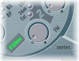
Chapter 3 ES2 57
Modulate ES2’s Filter 2 Frequency
Filter 2 cuto frequency can be modulated by the sine wave of oscillator 1, which is always
generated, even when the oscillator is switched o. The level of this sine signal can be mixed
in at the output stage with the Sine Level parameter (see Sine Level enhanced ES2 sounds on
page 58).
The eect of such lter modulations in the audio spectrum is unpredictable, but the results tend
to remain harmonic if you avoid high modulation intensity values. The FM parameter is used to
dene the intensity of this lter frequency modulation.
Note: Don’t confuse this lter frequency modulation with the oscillator FM feature (oscillator 1
is modulated by oscillator 2). If oscillator 1 is frequency-modulated by oscillator 2, it does not
inuence the sine wave signal used to modulate the cuto frequencies. See Use frequency
modulation in ES2.
Filter 2 can also be driven to self-oscillation. If you set a very high resonance value, it produces a
sine wave. This self-oscillating sine wave distorts at the maximum resonance value. If you mute
all oscillators, you’ll only hear this sine oscillation. By modulating the cuto frequency, you can
produce eects similar to those produced by modulating the frequency of oscillator 1 with
oscillator 2.
Modulate lter FM
1 Set up a modulation routing as follows: modulation target LPF FM.
A sine wave, at the frequency of oscillator 1, is always used as the modulation source. Given this
default assignment and the direct relationship between the lter FM intensity and oscillator 1’s
frequency, you can set up a second routing to modulate Oscillator 1’s pitch.
2 Set up a modulation routing as follows: modulation target Pitch 1, source LFO1.
3 Adjust LFO settings.

Chapter 3 ES2 58
ES2 amplier parameters
Use ES2’s dynamic stage
The dynamic stage of a synthesizer denes the level, or perceived volume, of a played note. The
change in level over time is controlled by an envelope generator. For more information about
envelope generators, see Synthesizer basics overview on page 472.
ENV 3 is hard wired to the dynamic stage of the ES2—it is always used to control the level of
each note. See ES2 envelopes overview.
The dynamic stage can be modulated by any router modulation source.
Modulate the dynamic stage (Amp)
1 Set up a modulation routing as follows: modulation target AMP, source LFO1.
2 Make sure that via is set to O.
3 Adjust LFO settings.
A tremolo eect is created, with the level changing periodically, based on the current LFO 1
Rate value.
Sine Level enhanced ES2 sounds
The Sine Level knob mixes a sine wave (at the frequency of oscillator 1) directly into the
dynamic stage, independent of the lters. Even if you have ltered away the basic partial tone of
oscillator 1 with a highpass lter, you can reconstitute it with this parameter.
•In cases where oscillator 1 is frequency-modulated by oscillator 2 (if you have turned up FM
with the waveform selector), only the pure sine wave is mixed into the dynamic section, not
the distorted FM waveform.
•Any modulation of oscillator 1’s pitch, set in the router, aects the frequency of the sine wave
mixed in at this stage.
Note: The Sine Level knob is useful for adding warmth and a fat bass quality to the sound. Extra
body can be added to thin sounds with this parameter, given that oscillator 1 actually plays the
basic pitch.
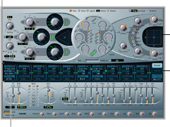
Chapter 3 ES2 59
ES2 modulation
ES2 modulation overview
ES2 is equipped with a huge number of modulation sources and targets, making it a synthesizer
that can generate extraordinary sounds that constantly evolve, sound like audio loops, or are just
plain expressive to play.
Modulation sources
Click here to
display the
Vector Envelope.
Planar Pad
Modulation router
•Modulation router: The modulation router—or router, for short—links modulation sources, such
as the envelope, to modulation targets, such as the oscillators and lters. The router features
ten modulation routings, arranged into columns. See Use the modulation router on page 60.
•Modulation sources: The modulation sources include the LFOs and envelopes. See ES2 LFO
overview on page 64 and ES2 envelopes overview on page 67.
•Vector Envelope: The Vector Envelope is an extremely sophisticated, loop-capable, multipoint
envelope that can control the Planar Pad and Triangle (oscillator mix parameter). The Vector
Envelope shares the space occupied by the modulation router and can be viewed by clicking
the Vector Envelope button to the right of the router. See Use the Vector Envelope on page 70.
•Planar Pad: The Planar Pad is a two-dimensional controller that facilitates the simultaneous
manipulation of two, freely assignable, parameters. It can be controlled with the Vector
Envelope. See Use the Planar Pad on page 77.
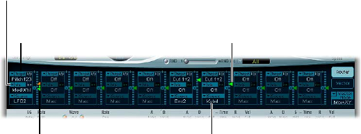
Chapter 3 ES2 60
ES2 modulation router
Use the modulation router
The modulation router—or router—spans the center of the ES2 interface. Click the Router button
to view it if the Vector Envelope is displayed (these components share the same section of the
interface). You can hide or show the router/Vector Envelope by clicking the disclosure triangle at
the lower left of the section. If you are new to synthesizer modulation routings, see Modulation
overview on page 488.
The modulation intensity slider
divides into two halves when a
via source is active.
Modulation sources are
shown at the bottom of
each modulation routing.
The modulation intensity
slider is not divided when
there is no active via source.
Modulation targets are
shown at the top of each
modulation routing.
Via sources are shown
in the middle of each
modulation routing.
Any modulation source can be connected to any modulation target, much like an old-fashioned
telephone exchange or a studio patch bay.
The modulation intensity—how strongly the target is inuenced by the source—is set with the
vertical slider to the right of the modulation routing.
The intensity of the modulation can itself be modulated: the via parameter denes a further
modulation source, which is used to control the modulation intensity. When via is active, you can
specify upper and lower limits for the modulation intensity.
Ten such modulation routings of source, via, and target can take place simultaneously. It doesn’t
matter which of the ten modulation routings you use. You can even select the same target
in several parallel modulation routings. You can also use the same sources and the same via
controllers in multiple modulation routings.
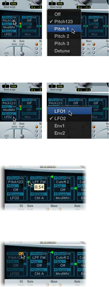
Chapter 3 ES2 61
Create a basic modulation routing
1 Choose the parameter you want to modulate from the Target pop-up menu.
2 Choose the parameter you want to use for modulation of the target from the Source
pop-up menu.
3 Vertically drag the Intensity slider to set a xed modulation intensity. When via is active, this
slider sets the minimum modulation intensity.
Bypass a modulation routing
mClick the “b/p” button at the top right of the modulation routing next to the Target parameter.
The Bypass (b/p) parameter enables or disables individual modulation routings, without
losing settings.
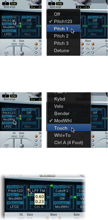
Chapter 3 ES2 62
Control ES2 modulation intensity with via sources
In a basic modulation routing comprised of a target and source, you can set a xed modulation
intensity by vertically dragging the Intensity slider to the right of the routing. The slider value
always denes a constant modulation intensity.
You can choose a further modulation source from the via pop-up menu, which controls
modulation intensity.
Choosing a value other than o for via divides the Intensity slider into two halves. Each half has
its own arrowhead.
•The upper half of the slider denes the maximum modulation intensity when the via
controller is set to its maximum value.
•The lower half of the slider denes the minimum modulation intensity when the via
controller—the modulation wheel, for example—is set to its minimum value.
•The area between the two slider halves denes the modulation range of the via controller.
Create a modulation routing that includes a via source
1 Choose a modulation target from the Target pop-up menu.
2 Choose a modulation source from the Source pop-up menu.
3 Choose the modulation source that you want to use for control of modulation intensity from the
via pop-up menu.
4 Vertically drag the upper arrowhead of the Intensity slider (to the right of the modulation
routing) to set the maximum modulation intensity.

Chapter 3 ES2 63
5 Vertically drag the lower arrowhead of the Intensity slider to set the minimum
modulation intensity.
Move the entire via range
mVertically drag the range (the area between the two slider halves).
Both arrowheads move simultaneously.
If this area is too small to drag, drag an unused section of the Intensity slider “track” to move
the area.
Set the modulation intensity to zero
mClick the zero symbol beside the via parameter.
Invert the eect of the via modulation source
mClick the via invert (inv) parameter to the right of the via parameter.
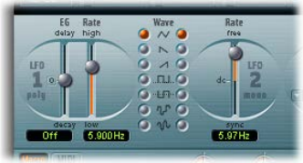
Chapter 3 ES2 64
ES2 LFOs
ES2 LFO overview
ES2 features two multi-waveform LFOs. Both are available as sources in the router.
LFO 1 is polyphonic, which means that if used for any modulation of multiple voices, they will
not be phase-locked. LFO 1 is also key-synced: each time you play a key, LFO 1 modulation of this
voice is started from zero.
To understand the non phase-locked characteristic more fully, imagine a scenario where a chord
is played on the keyboard. If LFO 1 is used to modulate pitch, for example, the pitch of one
voice may rise, the pitch of another voice might fall, and the pitch of a third voice may reach its
minimum value. As you can see, the modulation is independent for each voice, or note.
The key-sync feature ensures that the LFO waveform cycle always starts from zero, which results
in consistent modulation of each voice. If the LFO waveform cycles were not synchronized in this
way, individual note modulations would be uneven.
•LFO 1 is precongured to control the pitch of all three oscillators. It can be simultaneously
used for modulation of other parameters.
•LFO 1 can also be faded in or out automatically, courtesy of a built-in envelope generator.
•LFO 2 is monophonic, which means that the modulation is identical for all voices. For
example, imagine a chord is played on the keyboard. If LFO 2 is used to modulate pitch, the
pitch of all voices in the played chord rises and falls synchronously. LFO 2 is ideally suited for
creating rhythmic modulation eects that retain perfect synchronicity, even during project
tempo changes.
LFO parameters
•LFO 1 EG slider: Move to set the time it takes for the LFO modulation to fade in or fade out. The
value is displayed in milliseconds beneath the slider. Click the zero to turn the LFO 1 envelope
generator o.
•LFO 1 Rate slider: Move to set the frequency (speed) of LFO 1 modulation. The value is
displayed in Hertz (Hz) beneath the slider.
•LFO 1 Wave buttons: Choose the waveform used by LFO 1. See ES2 LFO waveforms on page 65.
• LFO 2 Rate slider: Move to set the frequency of LFO 2 modulation. LFO 2 can be synchronized
with the host application tempo.

Chapter 3 ES2 65
ES2 LFO waveforms
Choose a waveform for LFO 1 or LFO 2 with the LFO Wave buttons. The table outlines how these
waveforms can aect your sounds.
Tip: Try using the waveforms while a modulation routing of Pitch123 (the pitch of all three
oscillators) is engaged and running
Waveform Comments
Triangle Suitable for vibrato eects
Sawtooth Suitable for helicopter and space gun sounds. Intense
modulations of oscillator frequencies with a negative
(inverse) sawtooth wave lead to “bubbling” sounds.
Intense sawtooth modulations of lowpass lter cuto
and resonance creates rhythmic eects. The inverted
sawtooth waveform provides a dierent start point for
the modulation cycle.
Rectangle Rectangular waves periodically switch the LFO
between two values. The upper rectangular wave
switches between a positive value and zero. The lower
wave switches between a positive and a negative
value set to the same amount above/below zero. An
interesting eect can be achieved by modulating
Pitch123 with a suitable modulation intensity that
leads to an interval of a fth. Choose the upper
rectangular wave to do so.
Sample & Hold The bottom two LFO waveforms output random
values. A random value is selected at regular intervals,
dened by the LFO rate. The upper random wave
steps between randomized values—rapid switches
between values. The lower random wave is smoothed
out, resulting in uid changes to values. The term
Sample & Hold (S & H) refers to the procedure of
taking samples from a noise signal at regular intervals.
The values of these samples are then held until the
next sample is taken.
Tip: A random modulation of Pitch123 leads to an
eect commonly referred to as a random pitch
pattern generator or sample and hold. Try using very
high notes, at very high rates and high intensities—
you’ll recognize this well-known eect from hundreds
of science ction movies.
Chapter 3 ES2 66
Use ES2 LFOs
The ES2 LFO’s can be used to create delayed modulations, free modulations, and modulations
that are synchronized with your host application.
Set the LFO 1 modulation fade time
mTo fade in the modulation: Set a positive LFO 1 EG value.
The higher the value, the longer the delay time.
mTo fade out the modulation: Set a negative LFO 1 EG value.
The lower the slider is positioned onscreen, the shorter the fade out time.
Set up a delayed vibrato
LFO envelopes are most often used for delayed vibrato—many instrumentalists and singers
intonate longer notes this way.
1 Place the LFO 1 EG slider at a position in the upper half (Delay) and modulate the Pitch123 target
with the LFO1 source in the router.
2 Set a slight modulation intensity.
3 Set an LFO 1 Rate of about 5 Hz.
4 Choose the triangular wave as the LFO 1 waveform.
Set a free rate for LFO 2
mChoose a value in the upper half of the LFO 2 Rate slider range to run LFO 2 freely.
The rate is displayed in hertz.
Synchronize the LFO 2 rate with the song tempo
mChoose a value in the lower half of the LFO 2 Rate slider range to synchronize LFO 2 with the
host application tempo.
The rate is displayed in rhythmic values (when project tempo synchronization is active).
Synchronized rates range from speeds of 1/64-notes to a periodic duration of 32 bars. Triplet and
punctuated values are also available.

Chapter 3 ES2 67
ES2 envelopes
ES2 envelopes overview
ES2 features three envelope generators per voice. They are abbreviated as ENV 1, ENV 2, and ENV
3 in the interface and router. In addition, ES2 features the sophisticated Vector Envelope. See Use
the Vector Envelope.
To learn more about the roots of the term “envelope generator” and its basic function, see
Amplier envelope overview on page 486.
The parameters of ENV 2 and ENV 3 are identical. ENV 3 denes the changes in level over time
for each note played. You can think of ENV 3 as being hardwired to the router’s AMP modulation
target. ENV 2 controls the cuto frequency of both ES2 lters.
Note: All envelopes can be used to control multiple parameters simultaneously.
ES2 Envelope 1
Although Envelope 1 (ENV 1) appears to be simplistic, it is useful for a range of
synthesizer functions.
Decay/Release Mode
button
Trigger Modes menu
Attack via Velocity slider
Envelope 1 parameters
•Trigger Modes pop-up menu: Choose a mode to dene the trigger behavior of ENV 1.
•Poly: The envelope generator behaves as you would expect on any polyphonic
synthesizer: every voice has its own envelope.
•Mono: A single envelope generator modulates all voices in the same way. All notes must
be released before the envelope can be retriggered. If you play legato, or any key remains
depressed, the envelope does not restart its attack phase.
•Retrig: A single envelope generator modulates all voices in the same way. The envelope is
triggered by any key you strike, even when other notes are sustained. All sustained notes are
identically aected by the retriggered envelope.
•Attack via Velocity slider: The Attack time slider is divided into two halves. The lower slider
sets the attack time when keys are struck at maximum velocity. The top slider sets the
attack time at minimum velocity. Drag the area between the two slider halves to move both
simultaneously. If this area is too small to drag, click an unused portion of the slider, and
drag vertically.
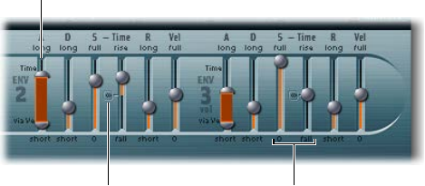
Chapter 3 ES2 68
•Decay/Release mode button: Switches ENV 1 between an Attack/Decay or an Attack/Release
envelope. The button label changes to reect the mode that is activated (D=Decay, R=Release).
•In Attack/Decay mode: The level falls to zero after the attack phase has completed, whether
or not the note is sustained. It decays at the same speed, even if you release the key. The
decay time is set with the D (Decay time) slider.
•In Attack/Release mode: The envelope level remains at its maximum after the attack phase is
over, while the key remains depressed. Following the release of the key, the level decreases
over the time period dened by the R (Release time) slider.
ES2 Envelopes 2 and 3
The feature sets of ENV 2 and ENV 3 are identical, but it is always the task of ENV 3 to dene the
level of each note—to modulate the dynamic stage, in other words. ENV2 is precongured to
control the Cuto frequency of both lters.
Both ENV 2 and ENV 3 can also be used simultaneously as sources in the router. The envelope
time parameters can be used as modulation targets in the router.
Attack Time slider is
divided into two halves
that determine the attack
time at maximum and
minimum velocities.
Click the center symbol
to set the Sustain Time
slider to its center value.
Sustain Time and
Sustain Level are set
independently in the ES2.
Envelope 2 and 3 Parameters
•Attack slider: Denes the time it takes for the level of a note to rise from a level (amplitude)
of zero to the set amplitude. The Attack time sliders of ENV 2 and ENV 3 are divided into two
halves.
•The lower half denes the attack time when the keys are struck hard, at maximum velocity.
The upper half denes the attack time at minimum velocity.
Drag the area between the two slider halves to move both simultaneously. If this area is too
small to drag, drag an unused portion of the slider vertically.
•Decay slider: Sets the time it takes for the level of a held note to fall to the sustain level, after
the attack phase has completed.
•If the Sustain level parameter is set to its maximum value, the Decay parameter has no eect.
•When the Sustain level is set to its minimum value, the Decay parameter denes the
duration or fade-out time of the note.
Chapter 3 ES2 69
•Sustain and Sustain Time sliders: The two sustain parameters interact with each other. One
controls the sustain level, and the other controls the sustain time. See Use ES2 Envelope 2 and
3 sustain controls on page 69.
•(R) Release Time slider: Denes the time required for the (sustain) level to decay to zero, after
the key is released.
•Vel (Velocity Sensitivity) slider: Determines the velocity sensitivity of the entire envelope. If
set to maximum, the envelope outputs its maximum level only when the keys are struck at
maximum velocity. Softer velocities result in a corresponding change to the envelope levels,
with a 50% velocity resulting in half-levels for each envelope-level parameter.
Use ES2 Envelope 2 and 3 sustain controls
When the Sustain Time (rise) slider is set to its center value, the Sustain (S) Level slider behaves
like the sustain parameter of any synthesizer ADSR envelope.
In this position, the Sustain (Level) slider denes the level that is sustained while the key remains
depressed, following completion of the Attack time and Decay time phases.
The Sustain Time slider denes the time it takes for the level to rise from the Sustain level back to
its maximum level—or to fall to zero:
•Settings in the lower half of the Sustain Time slider range (fall) determine the time required
for the level to decay from the sustain level to zero. The lower the slider position, the faster the
sound level decays.
•Settings in the upper half of its range (rise) determine the time required for the level to rise
from the sustain level to its maximum value. The higher the slider position, the faster the
sound level rises.
Emulate instrument behaviors with envelope decay modulation
1 Set up a modulation routing as follows: modulation target Env3Dec, source Kybd.
2 Make sure the Intensity slider is set to a negative value.
3 Adjust Env3 settings.
This routing simulates the behavior of pianos and plucked instruments, where high notes decay
faster than low notes.
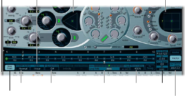
Chapter 3 ES2 70
Use the Vector Envelope
The Vector Envelope is a multipoint, loop-capable control source. Its sole purpose is to provide
real-time control of pointer movements in the Triangle and the Planar Pad. The Vector Envelope
shares the space occupied by the modulation router.
Each played voice has an independent Vector Envelope, which is triggered from its start point
with every new keystrike (MIDI note-on message).
Conceptually, the Vector Envelope—and Planar Pad and Triangle—may be dicult to grasp,
but some experimentation will reveal how easy these features are to use. Combining these
facilities with other synthesis options enables you to create truly unique sounds that are—quite
literally—moving.
Vector Mode
Planar Pad
Targets
Time ScalingLoop RateLoop ModeEnv Mode
Solo Point
Planar PadTriangle
Curve
Vector Envelope
Display the Vector Envelope
mClick the Vector Envelope button to the right of the router to display the Vector Envelope.
Turn the Vector Envelope on or o
mTo make the Vector Envelope active: Turn o the Solo Point button.
mTo deactivate the Vector Envelope: Turn on the Solo Point button.
When Solo Point is turned on, only the currently selected Triangle and Planar Pad positions of the
currently selected point are active.
Control the Planar Pad and Triangle with the Vector Envelope
mChoose the target for the Vector Envelope—the Planar Pad, Triangle, or both—from the Vector
Mode pop-up menu.
•O: The Vector Envelope does not control the Triangle or the Planar Pad. It is completely
turned o. You can manually set and control the pointers of the Triangle and the Planar Pad.
•Mix: The Vector Envelope controls the Triangle but not the Planar Pad.
•XY: The Vector Envelope controls the Planar Pad but not the Triangle.
•Mix+XY: The Vector Envelope controls both the Planar Pad and the Triangle.
Use the Vector Envelope shortcut menu
1 Right-click or Control-click anywhere in the Vector Envelope to open a shortcut menu of
commands and functions.
2 Choose any item in the menu to perform the operation.
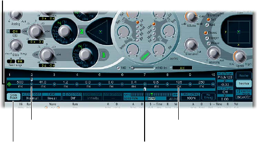
Chapter 3 ES2 71
Vector Envelope points, times, and loops
Use Vector Envelope points
The Vector Envelope time axis runs from left to right.
Loop point is shown on
row below time axis.
Sustain point is shown
on row above time axis.
Vector Envelope
time axis
Point 1
Point time value shown
in milliseconds (ms).
Up to 16 points can be displayed on the time axis (10 are shown in the gure above). Each point
can control the pointer positions of the Triangle and the Planar Pad.
The points are numbered sequentially, from left to right, along the time axis.
There are always at least three points: point 1 is the start point, point 2 is dened as the Sustain
point, and point 3 is the end point.
Any point can be declared the Sustain point. If a played note is held for a sucient length of
time and there’s no loop engaged, any envelope movement stops when the Sustain point
is reached. The Sustain point value is maintained until the key is released—until the MIDI
note-o command.
Any point can be declared the Loop point. The looped area spans the time between the Sustain
point and Loop point. In between these points you can create additional points that describe the
movements of the pointers in the Planar Pad and Triangle.
The more points you set, the more complex the movements that can be performed.
Select a point
mClick the point to select it.
Once selected, you can edit the point.
Create a new point
mShift-click between two existing points.
The segment that previously existed between the two old points is divided at the clicked
position. The sum of the two new segment times is equal to the time of the original undivided
segment. This ensures that any points that follow retain their absolute time positions. Existing
pointer positions in the Triangle and Planar Pad are xed, thus ensuring that newly created
points don’t aect any previously dened movements.
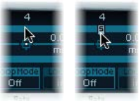
Chapter 3 ES2 72
Delete a point
mControl-click the point.
Revert to the default value for a point
Do one of the following:
mOption-click the Triangle.
The pointer is set to the center position of the Triangle, and all oscillators are set to output the
same level.
mOption-click the Planar Pad.
The pointer is set to the center position of the Planar Pad. Both axis values are set to zero.
Use Vector Envelope solo and sustain points
You use the Solo Point button to turn the Vector Envelope on or o. If the Solo Point button is
on, no dynamic modulations are generated by the Vector Envelope. In this scenario, the currently
visible pointer positions of the Triangle and Planar Pad are permanently in eect. These pointer
positions match the currently selected Vector Envelope point.
If you select another Vector Envelope point by clicking it, the pointer positions in the Triangle
and Planar Pad update to reect your selection. If the Solo Point button is on, the newly selected
point becomes the Solo point.
Note: You can independently turn o Vector Envelope modulation of the Planar Pad by setting
Vector Mode to o. See Use the Vector Envelope.
Any point can be declared the Sustain point. Assuming that the played note is held long
enough and there’s no loop engaged, any envelope movement stops when this Sustain point
is reached. The Sustain point value is maintained until the key is released—until the MIDI
note-o command.
Dene a point as the Sustain point
mClick in the turquoise strip above the chosen point.
The Sustain point is indicated by an S between the point and its number shown on the
turquoise strip.
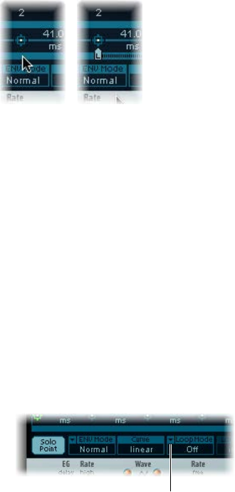
Chapter 3 ES2 73
Set up Vector Envelope loops
The Vector Envelope can run in one-shot mode, as long as the note is sustained; it can be set to
repeat a specic number of times or it can repeat indenitely, much like an LFO modulation. You
achieve repetitions by using the loop functions.
Although the loop parameters seem similar to the loop parameters available for samples, there
are signicant dierences between them. The Vector Envelope only supplies control signals that
are used to move the pointer positions of the Triangle and Planar Pad. The audio output of the
ES2 is not looped in any way.
Any point can be declared the Loop point. Provided that the note is held for a suitable length of
time, portions of the envelope can be repeated, or looped.
The looped area spans the time between the Sustain point and the Loop point. In between these
points you can dene several points that describe pointer movements in the Triangle and the
Planar Pad.
Dene a point as the Loop point
mClick in the turquoise strip below the chosen point.
A Loop point is indicated by an L in the strip below.
Set a Vector Envelope Loop mode
mChoose one of the following Vector Envelope Loop modes: O, Forward, Backward, and Alternate.
•O: When Loop mode is set to O, the Vector Envelope runs in one-shot mode from beginning
to end, if the note is held long enough to complete all envelope phases. The other loop
parameters are disabled.
•Forward: When Loop mode is set to Forward, the Vector Envelope runs from the beginning
to the Sustain point, and then begins to periodically repeat the section between the Sustain
point and the Loop point in a forward direction.
•Backward: When Loop mode is set to Backward, the Vector Envelope runs from the beginning
to the Sustain point, and then begins to periodically repeat the section between the Sustain
point and the Loop point in a backward direction.
•Alternate: When Loop mode is set to Alternate, the Vector Envelope runs from the beginning
to the Sustain point and then periodically switches to the Loop point, then back to the Sustain
point, alternating between backward and forward directions.
Click here to choose a
Loop mode.
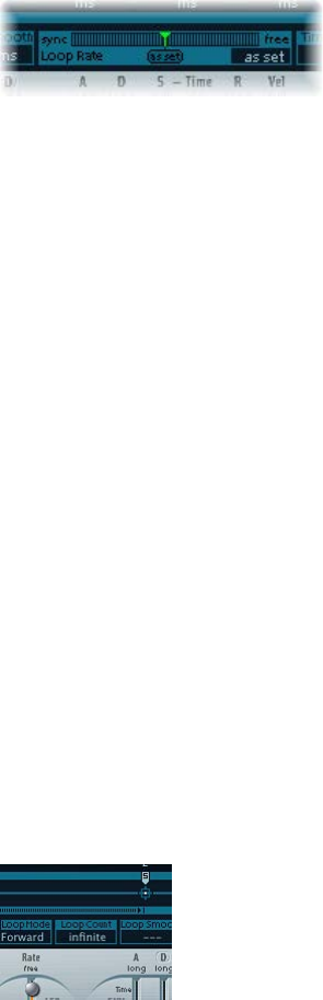
Chapter 3 ES2 74
Set the Vector Envelope Loop Rate
Do one of the following:
mDrag the green indicator in the center of the Loop Rate bar to the left or right.
mDrag vertically in the value eld “as set” (shown in the gure below).
The Vector Envelope loop can cycle at a dened speed. It can also be synchronized with the host
application tempo.
•As set: If you switch the Loop Rate to “as set,” the loop cycle length equals the sum of the times
between the sustain and Loop points. Click the eld labeled “as set” below the Rate slider to
select it.
•Rhythmic: If you set the Loop Rate to one of the rhythmic values (sync) by dragging the Loop
Rate indicator toward the left half of the slider, the loop rate follows the project tempo. You
can choose from 32 bars up to a 64th triplet note value.
•Free: You can also set a free Loop Rate by dragging the Loop Rate indicator toward the right
half of the slider (free). The value indicates the number of cycles per second.
Note: If Loop Rate is not switched to “as set,” and Loop mode (Forward, Backward, or Alternate)
is active, the times of points between the Loop and Sustain points and the Loop Smooth value
are shown as a percentage of the loop duration, rather than in milliseconds.
Make smooth Vector Envelope loop transitions
mWhen Loop mode is set to Forward or Backward, there is a transition from the Sustain
point to the Loop point. Turn on Loop Smooth to even out this transition, avoiding abrupt
position changes.
•If the Loop Rate parameter is set to Sync or Free, the loop-smoothing time is displayed as a
percentage of the loop cycle duration.
•If the Loop Rate parameter is “as set,” the loop-smoothing time is displayed in milliseconds
(ms).
Specify a Vector Envelope loop count
mThe Vector Envelope loop cycle can be repeated a specied number of times. Following the
dened number of repetitions, the Vector Envelope runs from the Sustain point onward. Possible
values are 1 to 10 and “innite.”
Chapter 3 ES2 75
Vector Envelope release phase behavior
There are two release phase options in the Env Mode menu: Normal and Finish.
In Normal mode, the release phase—the phase after the Sustain point—begins as soon as you
release the key (note o). In other words, the release phase starts from the Vector Envelope point
where you released the key. The following behaviors apply:
•If looping is turned o and the Vector Envelope reaches the Sustain point, the Sustain point
value is retained for as long as you hold a key.
•If looping is turned on and the Loop point is positioned before the Sustain point, the loop
cycles for as long as you hold a key.
•If looping is turned on and the Loop point is positioned after the Sustain point, the Vector
Envelope loop continues to cycle until the overall release phase of the sound, as determined
by the ENV 3 Release parameter, has completed.
If the Env Mode menu is set to Finish, the Vector Envelope does not immediately begin the
release phase when you release the key. Rather, it plays all points for their full duration until
the end point is reached, regardless of whether you hold the key or release it. The following
behaviors apply:
•If looping is turned o, the Sustain point is ignored. The Vector Envelope completes all points
up to the end point, regardless of whether you hold the key or release it.
•If looping is turned on, the Vector Envelope plays all points until it reaches the Loop point,
and then plays loop until the end point is reached. It does not matter if the Loop point is
positioned before or after the Sustain point.
•If looping is turned on, and Loop Count is set to a value other than “innite,” the Vector
Envelope continues on to the subsequent points—following completion of the specied
number of loop repetitions. If Loop Count is set to “innite,” the points after the loop
are irrelevant.
Vector Envelope point transition shapes
Curve denes the shape of the transition from point to point. Choose from nine convex and nine
concave shapes, plus “hold+step” and “step+hold,” which allow stepped modulations.
•step+hold: This curve jumps at the beginning of the transition.
•hold+step: This curve jumps at the end of the transition.
Note: You can use “hold+step” to create stepped vector grooves—with up to 15 steps.
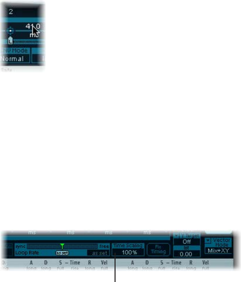
Chapter 3 ES2 76
Set Vector Envelope times
With the exception of the rst point, which is tied to the beginning of each played note,
every point has a Time parameter. This parameter denes the period of time required for the
position indicator to travel from the point that preceded it. The times are normally displayed in
milliseconds (ms).
Set a time value
mDrag the numerical value vertically.
Note: Changing a time value alters the absolute time positions of all subsequent points.
Set a time value without aecting the absolute time positions of later points
mControl-drag the Time parameter to increase or decrease the time required to reach the
following point.
The time setting of the ensuing point is simultaneously adjusted by a corresponding amount.
This ensures that the adjacent and all following points retain their absolute time positions.
Use Vector Envelope time scaling
You can stretch and compress the entire Vector Envelope. To double the Vector Envelope’s speed,
for example, set Time Scaling to 50%, rather than halving the time values of every point.
Click here to change the
time scale.
•The Time Scaling parameter ranges from 10% to 1000%. It is scaled logarithmically.
•If the Loop Rate is “as set,” scaling also aects the loop.
•If the Loop Rate is set to a free or synced value, the setting is not aected by the Time
Scaling parameter.
Normalize time scaling and the loop rate with Fix Timing
mClick Fix Timing to multiply the Time Scaling value by all time parameters. Time Scaling is reset to
100%.
There is no audible dierence. This is simply a normalizing procedure.
In cases where Loop Rate is set to a synced value, clicking Fix Timing switches the Loop Rate to
“as set,” thus preserving the absolute rate.
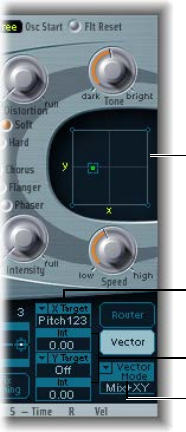
Chapter 3 ES2 77
Use the Planar Pad
The Planar Pad has two axes—X (horizontal) and Y (vertical). Two user-dened parameters can be
modulated with the X and Y values, allowing you to use the mouse like a joystick.
The X and Y axes have positive and negative value ranges. When you drag the pointer (the
square icon), the values of both axes are continuously transmitted.
Vector Mode menu
Vector Intensity parameters
Vector Target menus
Planar Pad
The Vector X and Vector Y Target menus determine which parameter is modulated by pointer
movements in the Planar Pad. These modulation targets are identical to those in the router.
See ES2 oscillator modulation targets on page 78, ES2 lter modulation targets, and Other ES2
modulation targets.
The position (coordinates) of the Planar Pad pointer is also available in the router, as the Pad-X
and Pad-Y source and via options. See ES2 modulation source reference on page 84 and Control
ES2 modulation intensity with via sources on page 62.
The maximum intensity, sensitivity, and polarity of the modulation is set with the Vector X Int
and Vector Y Int parameters.
Set the modulation intensity
mDrag vertically in the Vector X and Y Int elds.
Use a negative value to invert the modulation polarity.

Chapter 3 ES2 78
ES2 modulation target reference
ES2 oscillator modulation targets
The table below shows all oscillator-related modulation targets.
Target Comments
Pitch123 Modulates the frequencies (pitch) of all three
oscillators. If you select an LFO as the source, this
target leads to siren or vibrato sounds. Select one of
the envelope generators with zero attack, short decay,
zero sustain, and short release as the source for tom
and kick drum sounds.
Pitch 1 Modulates the frequency (pitch) of oscillator 1.
Slight envelope modulations can make the amount
of detuning change over time, when oscillator 1 is
sounding in unison with another (unmodulated)
oscillator. This also applies to the other Pitch targets
and is particularly useful for synthesizer brass sounds.
Pitch 2 Modulates the frequency (pitch) of oscillator 2.
Pitch 3 Modulates the frequency (pitch) of oscillator 3.
Detune Controls the amount of detuning between all three
oscillators. The sensitivity of all pitch modulation
targets is determined by the modulation intensity.
This is scaled as per the lists below, allowing you
to create very delicate vibrati in the cent range
(1/100 semitone), and huge pitch jumps by octaves.
•Modulation intensity from 0 to 8: steps are 1.25
cents.
•Modulation intensity from 8 to 20: steps are 3.33
cents.
•Modulation intensity from 20 to 28: steps are 6.25
cents.
•Modulation intensity from 28 to 36: steps are 12.5
cents.
•Modulation intensity from 36 to 76: steps are 25
cents.
•Modulation intensity from 76 to 100: steps are 100
cents.
This leads to the following rules of thumb for
modulation intensity values.
•Intensity of 8 equals a pitch shift of 10 cents.
•Intensity of 20 equals a pitch shift of 50 cents (one
quarter tone).
•Intensity of 28 equals a pitch shift of 100 cents (one
semitone).
•Intensity of 36 equals a pitch shift of 200 cents (two
semitones).
•Intensity of 76 equals a pitch shift of 1,200 cents
(one octave).
•Intensity of 100 equals a pitch shift of 3,600 cents
(three octaves).

Chapter 3 ES2 79
Target Comments
OscWaves Depending on the waveforms set in the three
oscillators, this target can be used to modulate:
•The pulse width of rectangular and pulse waves
•The amount of frequency modulation (oscillator 1
only)
•Noise color (oscillator 3 only)
•The position of the Digiwaves
OscWaves aects all oscillators simultaneously.
For further information about the eects of these
modulations, see Use pulse width modulation in
ES2 on page 39, Use frequency modulation in ES2 on
page 40, Use the ES2 noise generator on page 42, and
Use ES2 Digiwaves on page 42.
Osc1Wave Depending on the waveform selected for oscillator 1,
you can control the pulse width of rectangular and
pulse waves, the amount of frequency modulation, or
the position of the Digiwave. In classic FM synthesizers
the amount of FM is controlled in real time by
velocity-sensitive envelope generators. Select one of
the ENVs as the source for such sounds.
Osc2Wave The same as Osc1Wave, except that oscillator 2 does
not feature FM. Note that pulse width modulation also
works with both the synchronized rectangular and
ring-modulated rectangular waves.
Osc3Wave Oscillator 3 is the same as Osc1Wave and Osc2Wave
except that it does not feature FM or ring modulation.
Oscillator 3 features noise, the color of which can be
modulated with this parameter.
OscWaveB The transitions between Digiwaves during a
wavetable modulation (where you switch between
dierent Digiwaves) are always smooth. You can use
the OscWaveB target to continuously modulate the
shape of the transitions from smooth to hard. This
target applies to all oscillators.
Osc1WaveB If wavetable modulation is active for a Digiwave
(using the Osc1Wav target), you can use this target to
modulate the shape of the transition. When you are
frequency-modulating oscillator 1, the Osc1WaveB
target oers much higher FM intensities than either
the Osc1 FM or the Osc1Wave targets.
Osc2WaveB The same as above for a Digiwave using the Osc2Wav
target.
Osc3WaveB The same as above for a Digiwave using the Osc3Wav
target.
SineLev1 SineLevl (Sine Level) allows the sine wave level of
oscillator 1 to be modulated. The parameter denes
the level of the rst partial tone of oscillator 1. See
Sine Level enhanced ES2 sounds on page 58.

Chapter 3 ES2 80
Target Comments
OscLScle OscLScle (Osc Level Scale) modulates the levels of all
three oscillators simultaneously. A modulation value
of 0 mutes all oscillators, whereas a value of 1 raises
the gain of the entire mix by 12 dB. The modulation
is applied before the overdrive stage, allowing for
dynamic distortions.
Osc1Levl (Osc 1 Level) allows modulation of oscillator 1’s level.
Osc2Levl (Osc 2 Level) allows modulation of oscillator 2’s level.
Osc3Levl (Osc 3 Level) allows modulation of oscillator 3’s level.

Chapter 3 ES2 81
ES2 lter modulation targets
The table below includes all lter-related modulation targets.
Target Comments
Cuto 1 Modulates the Cuto Frequency parameter of Filter 1.
See Filter cuto and resonance overview on page 54.
Resonance 1 (Reso 1) Modulates the Resonance parameter of
Filter 1.
Cuto 2 Modulates the Cuto Frequency parameter of Filter 2.
Resonance 2 (Reso 2) Modulates the Resonance parameter of
Filter 2.
LPF FM Determines the intensity of the lowpass lter
frequency modulation (LPF FM) of Filter 2—with a
sine wave (at the same frequency as oscillator 1).
This parameter is described in Modulate ES2’s Filter 2
Frequency on page 57.
Cut 1+2 Modulates the cuto frequency of both lters in
parallel. This is like applying the same modulation to
Cuto 1 and Cuto 2 in two modulation routings.
Cut1inv2 Cut1inv2 (Cuto 1 normal and Cuto 2 inverse)
simultaneously modulates the cuto frequencies
of the rst and second lters inversely (in opposite
directions). Put another way, when the rst lter’s
cuto frequency is rising, the cuto of the second
lter falls, and vice versa.
In cases where you have combined Filter 1, dened
as a highpass lter, and Filter 2 in serial mode, both
act as a bandpass lter. Modulating the Cut1 inv 2
target results in a modulation of the bandpass lter’s
bandwidth in this scenario.
Filter Blend (FltBlend) modulates the Filter Blend parameter. See
Cross-fade between ES2 lters on page 51.

Chapter 3 ES2 82
Other ES2 modulation targets
The table below includes all other modulation targets.
Target Comments
Amp This target modulates the dynamic stage, or level of
voices. If you select Amp as the target and modulate
it with an LFO as the source, the level changes
periodically, and you hear a tremolo.
Pan This target modulates the panorama position of the
sound in the stereo spectrum. Modulating Pan with
an LFO results in a stereo tremolo (auto panning).
In unison mode, the panorama positions of all
voices are spread across the entire stereo spectrum.
Nevertheless, pan can still be modulated, with
positions being moved in parallel.
LFO1Asym (LFO1 Asymmetry) can modulate the selected
waveform of LFO 1. If a square wave, it changes pulse
width. If a triangle wave, it sweeps between triangle
and sawtooth. If a sawtooth wave, it shifts its zero
crossing.
LFO1Curve This target modulates the waveform smoothing of the
square and random wave. If the LFO is using a triangle
or sawtooth wave, it changes between convex, linear,
and concave curves.

Chapter 3 ES2 83
Scaled ES2 modulation targets
All of the following modulation targets result in a scaled modulation, which means that the
target parameter value is multiplied by the modulation value. This works as follows: a modulation
value of 0.0 results in no change, a modulation value of +1.0 equals a 10x multiplication, and a
modulation value of −1.0 equals a multiplication by 0.04.
Target Comments
LFO1Rate This target modulates the frequency (rate) of LFO 1.
You can automatically accelerate or slow down LFO 1’s
rate by modulating the LFO1Rate target with one of
the envelope generators (ENV) or with LFO2.
Env2Atck (Envelope 2 Attack) modulates the Attack time of the
second envelope generator.
Env2Dec (Envelope 2 Decay) modulates the Decay time of
the second envelope generator. In cases where
you’ve selected Env2Dec as the target and Velocity
as the source, the duration of the decaying note is
dependent on how hard you strike the key. Selecting
Keyboard as the source results in higher notes
decaying more quickly (or slowly).
Env2Rel Env2Rel (Envelope 2 Release) modulates the Release
time of the second envelope generator.
Env2Time Env2Time (Envelope 2 All Times) modulates all of
ENV2’s time parameters: Attack, Decay, Sustain, and
Release times.
Env3Atck Env3Atck (Envelope 3 Attack) modulates the Attack
time of ENV3.
Env3Dec Env3Dec (Envelope 3 Decay) modulates the Decay
time of ENV3.
Env3Rel Env3Rel (Envelope 3 Release) modulates the Release
time of ENV3.
Env3Time Env3Time (Envelope 3 All Times) modulates all ENV3
time parameters: Attack, Decay, Sustain, and Release
times.
Glide This target modulates the duration of the Glide
(portamento) eect. If you modulate Glide, with
Velocity selected as the source, the speed of the
keystrike determines the time it takes for the played
notes to reach the target pitch.

Chapter 3 ES2 84
ES2 modulation source reference
The following modulation sources are available:
Source Comment
LFO1 LFO 1 is used as a source.
LFO2 LFO 2 is used as a source.
ENV1 Envelope Generator 1 is used as a source.
ENV2 Envelope Generator 2 is used as a source.
ENV3 Envelope Generator 3 is used as a source. Envelope
Generator 3 always controls the level of the overall
sound.
Pad-X, Pad-Y Dene the axes of the Planar Pad as modulation
sources for the selected modulation target. See
Use the Planar Pad on page 77 and Use the Vector
Envelope on page 70.
Max Max sets the value of this source to +1. This oers
interesting options for controlling the modulation
intensity with all possible via values.
Kybd Kybd (Keyboard) outputs the keyboard position (the
MIDI note number). The center point is C3 (an output
value of 0). Five octaves below and above, an output
value of −1 or +1, respectively, is sent. Modulate the
Cut 1+2 target with the Kybd source to control the
cuto frequencies of the lters with the keyboard
position—as you play up and down the keyboard,
the cuto frequencies change. A modulation intensity
of 0.5 proportionately scales cuto frequencies with
keyboard note pitches.
Velo Velocity sensitivity serves as a modulation source.
Bender The pitch bend wheel serves as a bipolar modulation
source. This is also true when the Bend Range
parameter of the oscillators is set to 0.
ModWhl The modulation wheel serves as a modulation source.
For most standard applications, you’ll probably use
the wheel as the via controller. Traditionally, it is used
to control the intensity of periodic LFO modulations.
Used here, it can be employed for direct, static
modulations, such as controlling both lter cuto
frequencies (Target = Cut 1+2).
Touch Aftertouch serves as a modulation source. ES2 reacts
to poly pressure (polyphonic aftertouch). If you set
the Target to Cut 1+2, the cuto frequencies rise and
fall, depending on how rmly you press a key on
your touch-sensitive MIDI keyboard—after the initial
keystrike.
Whl+To Both the modulation wheel and aftertouch serve as
modulation sources.
MIDI Controllers A-F MIDI controllers available in the router are named
Ctrl A–F and can be assigned to arbitrary controller
numbers. See ES2 macro and controller assignment
overview on page 90.

Chapter 3 ES2 85
Source Comment
RndN01 RndNO1 (Note On Random1) outputs a random
modulation value between −1.0 and 1.0, that changes
when a note is triggered or retriggered. The (random)
note-on modulation remains constant throughout the
note duration, until the next note-on trigger. There is
no value change when playing legato while in legato
mode.
RndN02 RndNO2 (Note On Random 2) behaves like Note
On Random1, but it glides, rather than steps, to the
new random value, using the Glide time (inclusive of
modulation). It also diers from Note On Random 1
in that the random modulation value changes when
playing legato while in legato mode.
SideCh SideCh (Side Chain modulation) uses a side chain
signal as a modulation (trigger) signal. The side chain
source can be chosen from the Side Chain pop-up
menu in the upper gray area of the plug-in window. It
is fed to the internal envelope follower, which creates
a modulation value based on the current side chain
input signal level.

Chapter 3 ES2 86
ES2 via modulation source reference
The following sources may be used to control the modulation intensity.
Via source Comment
LFO1 The modulation undulates at the speed and waveform
of LFO 1, which controls the modulation intensity.
LFO2 The modulation undulates at the speed and waveform
of LFO 2, which controls the modulation intensity.
ENV1 ENV1 controls the modulation intensity.
ENV2 ENV2 controls the modulation intensity.
ENV3 ENV3 controls the modulation intensity.
Pad-X, Pad-Y Both axes of the Planar Pad are also available as
via sources, allowing you to control modulation
intensities with them.
Kybd Kybd (Keyboard) outputs the keyboard position
(the MIDI note number). The center point is C3 (an
output value of 0). Five octaves below and above,
an output value of −1 or +1, respectively, is sent. If
you select Pitch123 as the target, modulate it with
the LFO1 source, and select Keyboard as the via
value, the vibrato depth changes, depending on the
key position. Put another way, the vibrato depth is
dierent for notes higher or lower than the dened
Keyboard position.
Velo If you select Velo (Velocity) as the via value,
the modulation intensity is velocity sensitive—
modulation is more or less intense depending on how
quickly (how hard) you strike the key.
Bender The pitch bend wheel controls the modulation
intensity.
ModWhl If you select ModWhl (Modulation Wheel) as the via
value, the modulation intensity is controlled by your
MIDI keyboard’s modulation wheel.
Touch If you select Touch (Aftertouch) as the via value, the
modulation intensity is touch sensitive—modulation
is more or less intense depending on how rmly you
press the key of your touch-sensitive MIDI keyboard
after the initial keystrike (aftertouch is also known as
pressure sensitivity).
Whl+To Both the modulation wheel and aftertouch control
the modulation intensity.
MIDI Controllers A-F MIDI controllers available in the router are named
Ctrl A–F, rather than Expression, Breath, and General
Purpose 1–4 (MIDI Control Change Messages 16 to
19 are also known as General Purpose Slider 1/2/3/4).
These can be assigned to arbitrary controller numbers
with the Controller Assignments pop-up menus.

Chapter 3 ES2 87
Via source Comment
RndN01 RndNO1 (Note On Random1) outputs a random
modulation intensity value between −1.0 and
1.0, which changes when a note is triggered or
retriggered. The random note-on modulation remains
constant throughout the note duration, until the next
note-on trigger.Note: There is no value change when
playing legato while in legato mode.
RndN02 RndNO2 (Note On Random 2) behaves like Note On
Random1, but it glides, rather than steps, to the new
random intensity value, using the Glide time (inclusive
of modulation). It also diers from Note On Random 1
in that the random modulation value changes when
playing legato while in legato mode.
SideCh SideCh (Side Chain modulation) uses a side chain
signal as a modulation intensity (trigger) signal. The
side chain source can be chosen from the Side Chain
pop-up menu in the upper gray area of the plug-in
window. It is fed to the internal envelope follower,
which creates a modulation value based on the
current side chain input signal level.
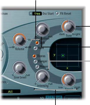
Chapter 3 ES2 88
ES2 integrated eects processor
ES2 is equipped with an integrated eects processor. Any changes to the parameters of these
eects are saved with each sound setting.
Intensity and Speed
parameters are shared
by the Chorus, Flanger,
and Phaser effects.
Click to choose Chorus,
Flanger, or Phaser effect.
Adjust to set the level of
Distortion.
Use the Tone parameter
to alter the tonal color of
the Distortion effect.
Click to choose a hard
or soft type of Distortion
effect.
You can activate only two eects at the same time.
•Distortion
•Choose the Chorus, the Flanger, or the Phaser eect. These eects share the same control
knobs—Intensity and Speed.
A chorus eect is based on a delay line, the output of which is mixed with the original,
dry signal. The short delay time is modulated periodically, resulting in pitch deviations.
The modulated deviations, in conjunction with the original signal’s pitch, produce the
chorus eect.
A anger works in a similar fashion to a chorus, but with even shorter delay times. The
output signal is fed back into the input of the delay line. This feedback results in the creation
of harmonic resonances that wander cyclically through the spectrum, giving the signal a
“metallic” sound.
A phaser mixes a delayed and an original signal. The delayed element is derived from an
allpass lter, which applies a frequency-dependent delay to the signal. This is expressed as
a phase angle. The eect is based on a comb lter, which is basically an array of inharmonic
notches—rather than resonances, as with the anger—that also wanders through the
frequency spectrum.
Chapter 3 ES2 89
Distortion parameters
•Soft button: Activates the Distortion eect Soft mode. The distortion circuit sounds somewhat
like a tube overdrive.
•Hard button: Activates the Distortion eect Hard mode. The distortion eect sounds like a fully
transistorized fuzz box.
•Distortion knob: Rotate to set the amount of distortion. Turn this knob to zero to disable
the eect.
•Tone knob: Rotate to control the treble portion of the distortion signal.
Chorus, Flanger, or Phaser parameters
•When Chorus is on:
•Intensity knob: Rotate to set the depth of the eect—how “rich” the modulation is. Turn this
knob to zero to turn o the eect.
•Speed knob: Rotate to set the modulation rate.
•When Flanger is on:
•Intensity knob: Rotate to set the depth of the eect—how “cutting” the modulation is. Turn
this knob to zero to turn o the eect.
•Speed knob: Rotate to set the modulation rate.
•When Phaser is on:
•Intensity knob: Rotate to set the depth of the “sweeping” eect—the width of the
modulation. Turn this knob to zero to turn o the eect.
•Speed knob: Rotate to set the modulation rate.
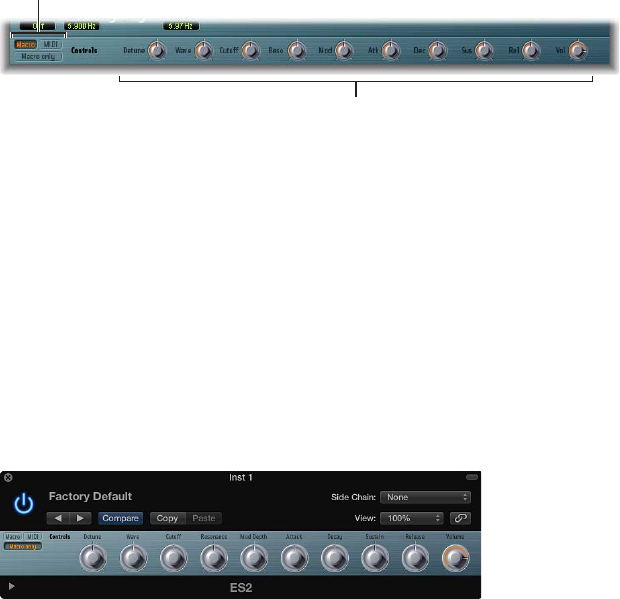
Chapter 3 ES2 90
ES2 macro controls and controller assignments
ES2 macro and controller assignment overview
The section at the bottom of the ES2 interface provides three views:
Macro control
parameters
Click here to
choose a view.
•Macro: Click to show a number of macro controls that aect groups of other parameters.
•MIDI: Click to assign MIDI controllers to particular modulation routings. See ES2 via modulation
source reference on page 86.
•Macro only: Click to replace the ES2 interface with a smaller view that is limited to the
macro controls.
ES2 macro controls
The macro knobs give you quick access to several linked, related parameters.
As you rotate any of the macro controls, one or more parameters in the ES2 interface update. For
example, adjusting the Detune macro control simultaneously aects the Analog parameter and
the coarse and ne oscillator Frequency parameters.
The macro parameters are settings-compatible with ES2-based GarageBand instruments. In other
words, you can use the ES2 and some GarageBand synthesizer settings interchangeably.
Important: The impact of each macro control is completely dependent on the parameter values
of the current setting. In some patches, a number of macro controls may have no eect.
Chapter 3 ES2 91
Make ES2 controller assignments
The Controller Assignments area enables you to assign your MIDi keyboard’s knobs, sliders, and
other controls to act as control sources for ES2 parameters. There are six menus, for Ctrl A to
Ctrl F. You can use any MIDI controller shown in the menus for these control sources.
These parameters are saved with each setting. They are updated only if the default setting that
is loaded on instantiating the plug-in is used or if the setting was saved with a project. This
approach helps you to adapt all MIDI controllers to the keyboard, without having to edit and
save each setting separately.
Controllers 0 and 32 are reserved for Bank Select messages, controller 1 is used as modulation
source in the router, controllers 33 to 63 work as LSB for controllers 1 to 31, controllers 64 to 69
are reserved for pedal messages, controllers 120 to 127 are reserved for channel mode messages.
In the MIDI specication, all controllers from 0 to 31 are known as Most Signicant Byte (MSB)
controller denitions. Each of these controllers (0 to 31) also contains a Least Signicant Byte
(LSB) controller denition (32 to 63). Use of this secondary LSB controller in conjunction with the
MSB controller allows for a resolution of 14 bits instead of 7 bits. The ES2 recognizes these control
change messages—the breath or expression controllers, for example.
To explain:
•14-bit controllers are pairs of normal Control Change (CC) messages, where the number of the
second CC message (the LSB) is 32 higher than the rst CC message (the MSB). Examples of
valid 14-bit pairs are: CC1/33, CC7/39, and CC10/42.
•14-bit controllers have a resolution of 16,384 steps, allowing very precise control of plug-in
parameters. The rst CC message of a 14-bit pair (the MSB) has a coarse resolution of 128 steps.
Each of these steps can be divided into a further 128 substeps using the second CC message
(the LSB). This results in 128 x 128 = 16,384 steps.
•You don’t need to create new, or special, data types to use 14-bit controllers. The ner
resolution is achieved by complementing the assigned CC message (the MSB) with its LSB. The
CC message assigned in the ES2 can always be used alone if your MIDI controller isn’t capable
of sending 14-bit messages, thus limiting the resolution to 7-bit = 128 steps.
The 14-bit capability is the reason why CC numbers 33–63 can’t be assigned in the Ctrl A–F
menus. Using these (LSB) CC numbers would result in changing 1/128th of the parameter
range—or put another way, 128 continuous steps out of 16,384.
Assign a MIDI controller
1 Click the MIDI button in the lower-left corner to display the Controller Assignments.
2 Click any Ctrl A to Ctrl F menu, then choose the controller name/number that you want to use
from the list.
Learn a MIDI controller assignment
1 Click the MIDI button in the lower-left corner to display the Controller Assignments.
2 Choose the Learn item from a control menu (Ctrl A to Ctrl F).
3 Move the selected controller on your MIDI keyboard or controller.
Note: If no suitable MIDI message is received within 20 seconds, the selected control reverts to
the previous value/assignment.

Chapter 3 ES2 92
ES2 extended parameters
ES2 provides additional parameters that can be accessed by clicking the disclosure triangle at
the lower left of the interface.
Extended parameters
•MIDI Mono Mode pop-up menu: Choose O, On (with common base channel 1), or On (with
common base channel 16).
In either mode, each voice receives on a dierent MIDI channel. Controllers and MIDI messages
sent on the base channel aect all voices.
•Mono Mode Pitch Range pop-up menu: Choose 0, 24, or 48.
The chosen pitch bend range aects individual note pitch bend messages received on
all but the common base channel. The default is 48 semitones, which is compatible with
Mobile GarageBand's keyboard in pitch mode. When using a MIDI guitar, 24 semitones is the
preferable setting because most guitar to MIDI converters use this range by default.
Create random ES2 sound variations
Use ES2’s randomization parameters
ES2 oers a powerful feature that enables you to randomly vary sound parameters. You can
dene the amount of random variation and restrict variations to specic sonic elements. The
random sound variation feature will inspire and aid you when creating new sounds.
You can set the amount of random parameter alteration with the Random Intensity slider.
The random sound variation feature always alters parameters as they are currently set, not based
on the original setting le. Therefore, clicking RND repeatedly results in a sound that increasingly
diers from the original setting.
Randomly alter a sound
mClick the Randomize button.
The randomize process is triggered by a single click and can be repeated as often as you like.
Increase the amount of random variation
mMove the Random Intensity slider farther to the right.
Create several slight variations of the current setting
mReload the original setting after each random alteration, saving each with a new name.

Chapter 3 ES2 93
Restriction of ES2 randomization
You can restrict randomization to particular groups of parameters using the Randomize Section
pop-up menu.
Some aspects of your sound may already be ideal for the sound you had in mind. For example,
your sound setting has a nice percussiveness, and you’d like to try a few sonic color variations
while retaining this percussive feel. To avoid the random variation of any attack times, you can
restrict the variation to oscillator or lter parameters. You do this by setting the RND Destination
to Waves or Filters, thus excluding the envelope parameters from the variation process.
Note: The Master Level, Filter Bypass, and oscillator on/o parameters are never randomized.
Also, randomizations of the Vector Envelope turn the Solo Point parameter o.
You can restrict random sound variations to the parameter groups outlined below:
Randomize section Comments
All All parameters, with the exception of those
mentioned above, are randomized.
All except router and Pitch All parameters, with the exception of router
parameters and the basic pitch (semitone settings of
the oscillators), are altered. Oscillator ne-tuning is,
however, randomized.
All except Vector Env All parameters, with the exception of Vector Envelope
parameters, are altered. This maintains the rhythmic
feel of a given setting.
Waves Only the oscillator Wave and Digiwave parameters are
altered. Other oscillator parameters (tuning, mix, and
modulation routings in the router) are excluded.
Digiwaves New Digiwaves are selected for all oscillators. Other
oscillator parameters (tuning, mix, and modulation
routings in the router) are excluded.
Filters The following lter parameters are varied: Filter
Structure (series or parallel), Filter Blend, Filter Mode,
Cuto Frequency, and Resonance for Filters 1 and 2.
The Fatness and Filter FM parameters of Filter 2 are
also randomized.
Envs All parameters of all three envelopes (ENV 1, ENV 2,
and ENV 3) are randomized. The Vector Envelope is
excluded.
LFOs All parameters of both LFOs are varied.
Router All router parameters—in all modulation routings—
are varied (all intensities, target, via, and source
parameters are changed).
FX All eects parameters are randomized.
Vector Envelope All Vector Envelope parameters are varied, including
the X/Y routing of the Planar Pad.
Vector Env Mix Pad The oscillator mix levels of the Vector Envelope points
are altered. The rhythm and tempo of the modulation
(the time parameters of the points) are not changed.

Chapter 3 ES2 94
Randomize section Comments
Vector Env XY Pad Options The Planar Pad pointer positions (the Vector Envelope
points) are randomized. The X/Y routing, however,
is not changed. The rhythm and tempo of the
modulation (the time parameters of the points) are
also left unaltered.
You can specify a single direction for randomization
by choosing either:
•Vector Env XY Pad X only
•Vector Env XY Pad Y only
Vec Env Times Only the time parameters of the Vector Envelope
points are altered.
Vec Env Structure The Vector Envelope structure is altered. This
includes: All times, the Sustain point, the number of
points, and all loop parameters.
Vec Env Shue Times The Vector Envelope shue times (within loops) are
altered. This includes the Loop Smooth value, if Loop
Mode is set to Forward or Backward.
Chapter 3 ES2 95
ES2 tutorials
Create ES2 sounds from scratch
ES2 sound design from scratch overview
The “Create ES2 sounds from scratch” tutorials guide you—from the ground up (from scratch)—
through the creation of commonly used sounds. The ES2 sound design with templates on
page 106 tutorials also guide you through the sound creation process, but you use a number of
templates as your starting point.
To see the settings for these tutorials in the ES2 window, choose Tutorial Settings from the
Settings pop-up menu.
The Analog Saw Init tutorial setting is designed to be used as a starting point when you are
programming new sounds from scratch. When programming entirely new sounds, professional
sound designers like to use this type of setting, which has an unltered sawtooth wave sound
without envelopes, modulations, or any gimmicks. This type of setting is also useful when you
are getting to know a new synthesizer. It allows you to access all parameters without having to
consider any preset values.
•Start with the lters, the heart of any subtractive synthesizer. Check out the four lowpass lter
types—12 dB, 18 dB, 24 dB, and fat (Filter 2)—with dierent values for Cut (Cuto Frequency)
and Res (Resonance). Dene Env 2 as the lter envelope. This modulation wiring is preset in
the Router.
•Set Filter Blend to its leftmost position, which allows you to listen to Filter 1 in isolation. In
many circumstances, you’ll probably prefer Filter 1, but Filter 2 has its advantages. In addition
to the lowpass lter with 12 dB/octave slope (Lo), Filter 1 also oers a highpass, peak, bandpass
(BP), and band rejection (BR) mode. Filter 2’s lowpass sounds “softer” when compared with
Filter 1. It is best-suited to sounds where the lter eect is or should be less audible, such as
with Strings and FM sounds. Distorted TB-303-style sounds are more easily achieved with
Filter 2.
•This setting is also ideal for experimenting with dierent oscillator waveforms.
Chapter 3 ES2 96
Create fat ES2 sounds
“Fat” synthesizer sounds have always been popular and are likely to remain so, given their use in
modern trance, techno, R & B, and other styles.
Create fat ES2 sounds with oscillator detuning and unison mode
The Analog Saw 3 Osc setting features three detuned oscillators, and sounds fat as it is. The
following introduces you to some additional tools to fatten the sound even more.
In many factory settings, the Unison mode is active. This demands a lot of processing power. If
your computer isn’t fast enough, you can switch o the Unison mode and insert an Ensemble
eect in a bus, for use with several plug-ins. This saves processing power. You can also save CPU
resources by freezing or bouncing several software instrument tracks.
Do the following:
mCheck out the three-oscillator basic sound with dierent lter and envelope settings.
mCheck out the chorus eect at dierent Intensities and speeds.
mEngage Unison mode and select a higher setting for Analog. Because the sound is polyphonic,
each note is doubled. The number of notes that can be played simultaneously is reduced from
10 to 5. This makes the sound rich and broad. Combining Unison and higher values for Analog
spreads the sound across the stereo or surround spectrum.
In many factory settings, the Unison mode is active. This demands a lot of processing power. If
your computer isn’t fast enough, you can switch o the Unison mode and insert an Ensemble
eect in a bus, for use with several plug-ins. This saves processing power. You can also save CPU
resources by freezing or bouncing several software instrument tracks.
Create detuned ES2 monophonic sounds and eects
The Analog Saw Unison setting is a fat, heavily detuned, unltered basic sound. Three sawtooth
oscillators are used, but they are further detuned. The combination of Unison and Analog (set to
a high value) is essential—but this time monophonic mode is used to stack ten voices. Without
further eects, the result is a huge lead sound, much like those used in countless dance and
trance productions. With appropriate lter and envelope settings, electro sounds that are ideal
for arpeggiation and sequencing can easily be set up.
Do the following:
mSet the Cuto Frequency of Filter 2 to 0. This activates the preset lter envelope. Feel free to
check out dierent envelope settings.
mSwitch Osc 1 to sound one or two octaves lower.
mIncrease Drive or Distortion.
mSet Env 2 to be velocity sensitive. This allows for velocity-sensitive lter modulations.
mInsert a delay eect in the instrument channel strip of the ES2 (or a bus target).
Chapter 3 ES2 97
Create ES2 bass sounds
Not every sound needs to consist of several oscillators. There are numerous simple, eective,
sounds that make use of a single oscillator. This is especially true of synthesizer bass sounds,
which can be created quickly and easily with the Analog Bass Clean setting.
Create clean single-oscillator bass sounds
In the Analog Bass Clean setting, the basic sound is a rectangular wave that is transposed down
by one octave. The sound is ltered by Filter 2. What’s special about this sound is its combination
of Legato and Glide (portamento). When you play staccato, no glide eect occurs. When you play
legato, the pitch smoothly glides from one note to another. All keys must be released before you
strike a new key, in order to retrigger the envelopes.
Do the following:
mCheck out dierent lter and envelope settings.
mReplace the rectangular wave with a sawtooth.
mVary the Glide settings.
Tip: It’s best to make your edits while a bass line is playing. Create or play a monophonic bass
line, with most notes played staccato, but some legato. This can provide some interesting results
with very long Glide values.
Create distorted analog basses
In the Analog Bass Distorted setting, Filter 1 is engaged, with high settings for Drive and
Distortion. This lter is better suited to the creation of distorted analog sounds than Filter 2.
Do the following:
mCheck out Filter 2 by setting Filter Blend to its rightmost position. Notice that Filter 1 works
better with distorted sounds.
mTo control the lter modulation, move the green sliders of the rst modulation routing in the
router. This controls the modulation intensity.
Chapter 3 ES2 98
Create ES2 FM sounds
In the ES2, oscillator 1 is always the carrier, and oscillator 2 the modulator. In other words,
oscillator 2 modulates oscillator 1.
The FM Start setting is great for familiarizing yourself with linear frequency modulation (FM)
synthesis.
Use FM Intensity and Frequency to create new sounds
Load the FM Start setting to hear an unmodulated sine sound, generated by oscillator 1.
Oscillator 2 is switched on and set to produce a sine oscillation as well, but its level is set to
0: Drag the small square in the uppermost corner of the Triangle to change the settings.
Do the following:
mAdjust the intensity of the frequency modulation by slowly moving the wave selector from
Sine to FM. You will hear a typical FM spectrum, with the carrier and modulator set to the
same frequency.
mAlter the modulator frequency (oscillator 2) by adjusting Fine Tune from 0 c to 50 c. You’ll hear a
very slow frequency modulation, which can be compared to the eect of an LFO. The frequency
modulation, however, takes place in the audio spectrum. It is adjusted in semitone steps by the
frequency selector. Check out the entire range from −36 s to +36 s for oscillator 2. You’ll hear a
broad spectrum of FM sounds. Some settings will remind you of classic FM synthesizer sounds.
mSelect other waveforms for oscillator 2. Sine is the classic, standard FM waveform, but other
waveforms lead to interesting results as well, especially the Digiwaves.
mYou will achieve further interesting results by altering the carrier (oscillator 1) frequency.
Check out the entire range, from −36 s to +36 s here, as well. The odd intervals are especially
fascinating. Note that the basic pitch changes when you do this.
Control ES2 FM intensity with an envelope and FM scaling
In the FM Envelope setting, you can control the FM intensity with an envelope, generated by
Envelope 2. The modulation target is the range that falls between Sine and FM in the oscillator
wave selector. The rst Router channel is used for this modulation routing. You can control a
wider range by using additional modulation routings, which have been pre-prepared for you. All
you need to do is set their values. Because these modulations work without velocity sensitivity,
you can set them in the Editor view by moving both the lower and upper fader halves to their
topmost positions.
Do the following:
mSet the second modulation routing to 1.0. You’ll hear how the modulation now “wanders”
through a broader sound range.
mSet modulation routings 3 and 4 to a value of 1.0 as well, and listen to the increase in the
sound range.
mAfter these drastic augmentations to the modulation range, the sound becomes uneven across
the keyboard. In the lower and middle ranges it sounds nice, but in the upper key range the
FM intensity appears to be too severe. You can compensate for this eect by modulating the
Osc 1 Wave target by keyboard position (kybd) in modulation routings 5 and 6. This results in a
keyboard scaling of the FM intensity.
mBecause the sound range is so vast (due to the four modulations), two modulation routings
are required to compensate for this. Set the lower slider halves to their lowest positions. Good
keyboard scaling is essential for any FM sound.
Chapter 3 ES2 99
Use FM Drive and Filter FM to change the tonal color
The FM Drive setting illustrates how dramatically the character of FM sounds can be altered
when you apply Drive and Filter FM. The results are reminiscent of the feedback circuits of classic
FM synthesizers.
Do the following:
mCheck out dierent Drive and Filter FM settings.
mLower the Cuto Frequency of Filter 2 to 0. Envelope 2 modulates Filter 2. This modulation
routing is already present in the setting.
Create FM sounds with Digiwaves
In the FM Digiwave setting, a Digiwave is used as an FM modulator. This results in bell-like
spectra from only two operators. With traditional FM synthesis, this type of timbre could normally
be produced only with a larger number of sine oscillators.
To create a fatter, undulating, and atmospheric quality to the sound, the polyphonic Unison
mode has been engaged. Filter and amplitude envelopes have been preset to shape the sound.
Do the following:
mCheck out the variety of Digiwaves as FM modulation sources.
mCheck out dierent Analog parameter values.
Create FM sounds with wavetables
You can program the most vivid FM sounds when the modulation source morphs between
dierent Digiwaves. The morphing in the FM Digiwave setting is controlled by LFO 2. The tempo
of LFO 2, and therefore the morph, depends on the host application tempo—here, two bars.
Do the following:
mSet LFO 2 to dierent waveforms. Lag S/H (smooth random), in particular, should be fun.
mCheck out dierent FM intensities and oscillator frequencies.
mAlter the modulation intensity of the rst modulation routing (LFO2 modulates Osc2 Wave) and
the LFO 2 rate.
Create distorted FM sounds with monophonic unison
The FM Megafat setting is well-suited for distorted basses and guitar-like sounds. This sound gets
rather “rude” in the upper key range. This cannot be compensated for with key scaling, but not
every sound has to be “nice” across the entire keyboard range!
Do the following:
mCheck out extreme detunings by adjusting the Analog parameter.
mCheck out the Flanger with this sound.
mEngage the lter envelope by lowering the Cuto Frequency of Filter 2 down to 0.
mAdd some Glide to lead sounds.
mAs always when it comes to FM, you can dramatically alter the sound by varying the frequencies
of the oscillators. Make sure you check out the odd intervals, as well.
Create FM sounds with unusual spectra
Chapter 3 ES2 100
If you’re unconcerned with the pitch of your sound, you can get the weirdest spectra out of odd
frequency ratios—oscillator intervals.
The FM Out of Tune setting oers a bell-like sound, reminiscent of a ring modulator. It was
achieved through a setting of 30 s 0 c, with the modulator set to a value of 0 s 0 c. Sounds like
this were commonly used in the electronic music of the eighties and have had a resurgence in
popularity in ambient and trance music styles.
You can further develop the sound by applying ltering, envelope modulations, and eects.
There is, however, one small problem—the sound is out of tune.
Do the following:
mUse oscillator 3 as a reference for the tuning of the FM sound by dragging the pointer in
the Triangle.
mYou’ll notice that the sound is ve semitones too high (or seven semitones too low, conversely).
mTranspose both oscillators 1 and 2 ve semitones (500 ct) lower. Transposing them upward is not
practical, as you’d need to select 37 s 0 c for oscillator 1, which has a maximum value of 36 s 0 c.
mIt’s important to maintain the frequency ratio (interval) between oscillators 1 and 2. This means
that oscillator 1 sounds at 25 s O c and oscillator 2 at −5 s 0 c.
Chapter 3 ES2 101
Create ES2 PWM sounds
Pulse width modulation (PWM) is one of the most essential features of any analog synthesizer.
Set up a basic PWM sound
mChoose the PWM Start setting, and move the Wave control slowly back and forth between the
rectangular and the pulse wave symbols. Both are green. What you will hear is a manual pulse
width modulation.
mChoose the PWM Slow setting. Here, LFO 1 controls the pulse width modulation source, not your
manual movements. The result should be quite similar.
mRaise the LFO 1 rate from its preset value of 0.230 to 4.400. The result is a classic, fast PWM.
mIn this and the next step, the PWM is set so that it sounds slower in the lower keyboard range
and faster in the upper range. This is desirable for many sounds, such as synthetic strings. First,
reduce the LFO 1 Rate to 3,800.
mChange the modulation intensity of the second router channel (target = LFO1 Rate,
Source = Kybd) to 0.46. This alters the scaling of the PWM, making it sound faster in the treble
range. You can also hear this type of eect in the PWM Scaled setting.
Tip: Avoid Drive and Distortion with PWM sounds.
To make the sound fatter
mAdd oscillator 3, which can also be pulse width modulated. In fact, even the rst oscillator can
deliver PWM. In the PWM 2 Osc setting, both oscillators are detuned quite signicantly. Develop
your own personalized PWM string sound, using this setting as your base.
mAdjust the Chorus intensity. You’ll probably choose higher values, which make the sound
rather broad.
mProgram Envelope 3 according to your taste. You should, at the very least, raise the attack
and release times. Dene it to react to velocity, if you prefer. If you want to use the sound for
something other than a simple pad, a shorter Decay Time and a lower Sustain Level of about 80
to 90% may be more appropriate.
mReduce the Cuto Frequency and Resonance of Filter 1 to make the sound softer.
mSave the new setting.
mCompare the result with the original PWM 2 Osc setting. You’ll hear that the sound has
undergone a remarkable evolution.
mAlso compare it to PWM Soft Strings, which was created as described above. You’ll probably
notice a few similarities.
Chapter 3 ES2 102
Create ES2 ring modulated sounds
A ring modulator takes its two input signals and outputs their sum and dierence frequencies.
In the ES2, oscillator 2 outputs a ring modulation, which is fed with a square wave of oscillator 2
and the wave of oscillator 1, when Ring is set as oscillator 2’s waveform.
Odd intervals (frequency ratios) between the oscillators result in bell-like spectra, much like those
heard in the Ringmod Start setting.
The third oscillator can be used as a tuning reference, to maintain a kind of basic tuning. On
occasion, you may nd that it’s nice to leave the sound out of tune—for use as a source of
overtones and harmonics for another basic wave, supplied by oscillator 3.
Create an atmospheric bell sound
Try the following with the Ringmod Start setting:
mExperiment with the various frequency ratios of oscillators 1 and 2. You may want to use the 29 s
0 c/21 s 0 c ratio, which doesn’t sound out of tune at all. Ring modulation is not only useful for
bell-like sounds, it’s also good for a great variety of spectra that tend to sound weird at lower
frequency settings. Also try alterations to the ne-tuning of the oscillators.
mCheck out an Intensity of 50% and a Rate set to around 2/3 of the maximum value for the
Chorus eect.
mSet the Attack and Release Times of Envelope 3 to taste.
mCheck out Drive and Filter FM if you like your sounds a little “out of control.”
mThe rest is up to you.
Create ES2 oscillator sync sounds
If you select the synced square and sawtooth waveforms for oscillators 2 and 3, they are
synchronized with oscillator 1. In the Sync Start setting, only oscillator 2 is audible, and
oscillator 3 is switched o.
Typical sync sounds feature dynamic frequency sweeps over wide frequency ranges. These
frequency modulations (the sweeps) can be applied in various ways.
Enhance the Sync Start setting
Do the following:
mTry the pre-programmed pitch modulation, assigned to the modulation wheel rst.
mIn the second router channel, an envelope pitch modulation has been preprogrammed
(target = Pitch 2, Source = Env 1). Setting the minimum value to 1.0 results in a typical sync
envelope. Also check out shorter Decay Times for Envelope 1.
mTo avoid a sterile, lifeless sound (after the decay phase of the envelope), you may also want
to modulate the oscillator frequency with an LFO. Use the third router channel, and set the
minimum modulation applied by LFO 1 to about 0.50.
mSubstitute the synchronized square wave with the synced sawtooth wave, and see if you like
the results.
Note: Pulse width modulation is also available via the synchronized square wave of oscillators 2
and 3. A modulation of the wave parameters of these two oscillators results in a PWM when the
synced square wave is selected.
Chapter 3 ES2 103
Vector synthesis in the ES2
This tutorial provides some hints for Vector Envelope programming.
Familiarize yourself with the Vector Envelope
In the Vector Start setting, the “mix” of the oscillators is controlled by the Vector Envelope. Each
oscillator has been set to a dierent waveform.
mSwitch from the Router view to Vector view.
mIn its basic (default) setting, the Vector Envelope has three envelope points. Point 1 is the start
point, point 2 the Sustain point, and point 3 is the target in the release phase. By clicking the
points, you can see that the mix is always set to 100% for oscillator 1, in the Triangle.
mClick point 2, and drag the pointer in the Triangle to oscillator 2. You’ll hear a square wave,
instead of oscillator 1’s sawtooth.
mEngage the Vector Envelope by switching the Solo Point parameter o. When it is switched on,
you hear only the selected point, with no dynamic modulation. When Solo Point is switched o,
you’ll hear the sound moving from saw to square, with every triggered note.
mAlter the preset time of 498 ms between points 1 and 2.
mWhile holding down Shift, click between points 1 and 2. A new point 2 is created, and the point
formerly known as point 2 becomes point 3. The total time span between point 1 and point 3 is
divided into the times between points 1 and 2, and 2 and 3. The division takes place at the click
location. If you click at the exact midpoint, the new time spans are equal.
mClick the newly created point 2, and then drag its corresponding pointer in the Triangle to
oscillator 2.
mClick point 3, and drag its corresponding pointer in the Triangle to oscillator 3. Listen to the three
oscillators morphing from sawtooth to square to a triangular wave at the nal Sustain point.
mClick point 4 (the end point) and drag its corresponding pointer in the Triangle to oscillator 1, if
it’s not already there. Listen to how the sound returns to oscillator 1’s sawtooth wave, following
the release of the key.
Vector synthesis with the Planar Pad
The Vector Envelope setting starts where the Vector Start setting left o. You have a simple Vector
Envelope consisting of four points, which is set to modulate the oscillator mix (the Triangle).
In this example, the Vector Envelope is used to control two additional parameters—the Cuto
Frequency of Filter 2 and Panorama. These are preset as the X and Y targets in the Planar Pad.
Both have a value of 0.50.
Do the following:
mSwitch on Solo Point, to more easily listen to the settings for the single points.
mClick point 1. You will hear only oscillator 1’s sawtooth.
mDrag the pointer in the Planar Pad to the far left, which results in a low cuto frequency for
oscillator 2.
mClick Point 2. You will hear only oscillator 2’s rectangular wave.
mDrag the pointer in the Planar Pad all the way down, which results in the rightmost
panorama position.
mClick Point 3. You will hear only oscillator 3’s triangular wave.
Chapter 3 ES2 104
mDrag the pointer in the Planar Pad all the way up, which results in the leftmost
panorama position.
mSwitch on Solo Point. The sound begins with a strongly ltered sawtooth wave and turns into
an unltered square wave. It initially sounds from the right, and then it moves to the left while
morphing into a triangular wave. After you release the key, the saw sound is heard.
Use Vector synthesis loops
The basic sound of the Vector Loop setting—without the Vector Envelope—consists of three
elements:
•Oscillator 1 delivers a metallic FM spectrum, modulated by oscillator 2’s wavetable.
•Oscillator 2 outputs cross-faded Digiwaves (a wavetable), modulated by LFO 2.
•Oscillator 3 plays a PWM sound at the well-balanced, and keyboard-scaled, speed of LFO 1.
These heterogeneous sound colors are used as sound sources for the vector loop. Unison and
Analog make the sound fat and wide.
A slow, forward loop is preset. It moves from oscillator 3 (PWM sound, point 1) to oscillator 1
(FM sound, point 2), then to oscillator 3 again (PWM, point 3), then to oscillator 2 (wavetable,
point 4), and nally it returns to oscillator 3 (PWM, point 5). Points 1 and 5 are identical, which
prevents any transition from point 5 to point 1 in the forward loop. This transition could be
smoothed out with Loop Smooth, but this would make the rhythmic design more dicult
to program.
The distances between the points of the Vector Envelope have been set to be rhythmically
exact. Given that Loop Rate has been engaged, the time values are not displayed in ms,
but as percentages. There are four time values (each at 25%), which is a good basis for the
transformation into note values.
Do the following:
mSwitch o the Vector Envelope by setting Solo Point to on. This allows you to audition the
individual points in isolation.
mTake the opportunity to alter the pointer positions in the Planar Pad according to your taste. The
X/Y axes of the Planar Pad control the cuto frequency of Filter 2, and the panorama position.
Adjustments to these make the sound more vivid.
mActivate the Vector Envelope by setting Solo Point to o. Check the result, and ne-tune the
pointer positions in the Planar Pad.
mAlter the Loop Rate from the preset value of 0.09 up to 2.00. You will hear a periodic modulation,
much like that of an LFO. At this point, the modulation is not synchronized with the project
tempo. To synchronize the loop speed with the project tempo, move the Rate to the far left, and
set a note or bar value.
mYou can create faster rhythmic note values by clicking between two points and setting the new
time values—which result from the division that occurs—to a value of 12.5%, for example.
Chapter 3 ES2 105
Create kick drums with a self-oscillating lter and the Vector Envelope
Electronic kick drum sounds are often created with modulated, self-oscillating lters. This
approach can also be taken with the ES2, particularly when the Vector Envelope is used for
lter modulation. An advantage of the Vector Envelope, in comparison with conventional ADSR
envelopes, is its ability to dene and provide two independent decay phases. The distortion
eect applies the right amount of drive without sacricing the original sonic character of the
drum sound.
Note: To make the setting really punchy, you must activate Flt Reset, because all oscillators are
switched o in this setting, and the lter needs a little time to start oscillating. At the start of
each note, Flt Reset sends a very short impulse to the lter—making it oscillate from the outset.
By tweaking the Vector Kick setting you can create any dance-oor kick drum sound you can
think of.
Change the following parameters to create sound variations:
mFilter 2 slopes: 12 dB, 18 dB, 24 dB
mDistortion: Intensity and Soft or Hard
mEnvelope 3’s Decay Time: (D)
mVector Envelope Time 1 > 2: preset to 9.0 ms
mVector Envelope Time 2 > 3: preset to 303 ms
mVector Time Scaling
Create percussive synthesizer and bass sounds with two lter decay phases
As with the Vector Kick setting, the Vector Perc Synth setting uses the Vector Envelope to control
the lter cuto frequency, with two independently adjustable decay phases. This would not be
possible with a conventional ADSR envelope generator.
Try creating further percussive synthesizers and basses by varying these parameters:
mVector Envelope Time 1 > 2 (= Decay 1)
mVector Envelope Time 2 > 3 (= Decay 2)
mVector Time Scaling
mPoints 1, 2, and 3 (= Cuto Frequency) in the Planar Pad
mWaveforms (choosing other waveforms)
Chapter 3 ES2 106
Create ES2 sounds with templates
ES2 sound design with templates
There are a number of tutorial templates that you can open from the Settings pop-up menu
(choose the Tutorial Settings folder).
This programming tour of the ES2 is included as a part of the toolbox to help you learn the ES2’s
architecture through experimentation with these template sounds.
As you become more familiar with ES2 functions and parameters, you can create your own
templates to use as starting points when designing new sounds.
ES2 Slapped StratENV setting
The target of this setting is the sound of a Stratocaster, with the switch between bridge and
middle pickup in the middle position—in phase. It attempts to emulate the noisy twang
typical of this sound’s characteristics. This might be a useful template for emulations of fretted
instruments, harpsichords, clavinets, and so on.
Take a look at the sound’s architecture:
Osc 1 and Osc 3 provide the basic wave combination within the Digiwave eld. Changing the
Digiwaves of both in combination delivers a huge number of basic variations—some also work
pretty well for electric piano-type keyboard sounds.
Osc 2 adds harmonics with its synced waveform, so you should only vary its pitch or sync
waveform. There are a couple of values that can be changed here, which will give you a much
stronger, more balanced signal.
An old trick, which delivers a punchy attack, was used—to create an eect that the use of a
naked wave wouldn’t deliver, even with the best and fastest lters available: You use an envelope
(in this case, Env 1) for a quick “push” of a wavetable’s window—or all wavetables together, where
it makes sense.
Set up Envelope 1’s decay time for this short push by moving the wave selectors for all
oscillators. (Although it makes no sense to do this on the synced sawtooth oscillator, Osc 2, use
the envelope trick regardless.) This allows you to vary the punchiness of the content between:
•Envelope 1’s contribution to the overall attack noise and changing decay length—a short
decay results in a peak, a long decay results in a growl, as Envelope 1 reads a couple of waves
from the wavetable.
•Modulation destination—you can always assign this to each of the oscillators separately.
•Start point—you vary the wave window start with minimum and maximum control of EG1/
Osc. waves modulation: negative values for a start wave before the selected wave, positive
values for a start wave from a position behind the selected wave that rolls the table back.
Feel free to experiment with this wavetable-driving trick. The growl eect works well for brass
sounds, and some organs absolutely shine with a little click, courtesy of a wavetable push.
Envelope 2, which controls the lter, provides a slight attack when used for “slapped”
characteristics. Setting it to the fastest value eliminates the wah-like attack, while retaining
the punch.
For playing purposes, you’ll nd that LFO 2 is used as a real-time source for vibrato. It is assigned
to the mod wheel and pressure. Feel free to change the wheel and pressure settings
Chapter 3 ES2 107
Velocity is set up to be very responsive, because many synthesizer players don’t strike keys like a
piano player would with a weighted-action “punch.” Therefore, you should play this patch softly,
or you may nd that the slap tends to sweep a little. Alternatively, you can adjust the sensitivity
of the lter modulation’s velocity value to match your personal touch.
If required, increase the Voices value to maximum—six strings should be enough for a guitar, but
for held or sustained notes, a few extra voices may come in handy.
ES2 Wheelrocker setting
This ordinary organ patch doesn’t hold any deep, high-end sound design secrets—it is just
a combination of three oscillators with mixed wave levels. You’ll probably nd a dierent
combination that more closely matches your vision of what an organ sounds like. Check out
the Digiwaves.
Focus your attention on the mod wheel’s response—hold a chord, and bring the wheel in
by moving it slowly upward until you reach the top (maximum). The intention behind the
programming of this mod wheel modulation is to simulate an accelerating Leslie rotor speaker.
The modulation routings do the following:
•Modulation routing 1 assigns envelope 2 to Filter 1—the only one used for this patch—and
produces a little organ key click with the envelope. The lter is opened slightly (with Keyboard
as via) when you play in the higher keyboard range, with the maximum value.
•Modulation routings 2 and 3 bring in LFO 1 vibrato, and both oscillators are modulated out
of phase.
•Modulation routing 4 does not need to be adjusted, but you are free to do so. It has been set
up to use ENV1 to “push” the wavetable. Adjust ENV1 Decay to make the sound more pipe
organ-like. Adjust ENV1 Attack to sweep through the wavetable.
•Modulation routing 5 reduces the overall volume according to personal taste, but the
organ’s level shouldn’t increase too drastically when all modulations are moved to their
respective maximums.
•Modulation routings 6 and 7 detune oscillators 2 and 3 against each other, within symmetrical
values—to avoid the sound getting out of tune overall. Again, both work out of phase with
modulation routings 2 and 3; oscillator 1 remains at a stable pitch.
•Modulation routing 8 brings in LFO 1 as a modulator for panorama movement—this patch
changes from mono to stereo. If you prefer a full stereo sound with a slowly rotating Leslie in
its idle position, just set an amount equal to the chosen minimum value, thereby achieving a
permanent, slow rotation. Another modication you may wish to try is a higher value, resulting
in more extreme channel separation.
•Modulation routing 9 speeds up LFO 2’s modulation frequency.
•Modulation routing 10: A little cuto was added to Filter 1, increasing the intensity of the
big twirl.
Feel free to nd your own values. While doing so, keep in mind the fact that there are two
modulation pairs that should only be changed symmetrically—modulation routings 2 and 3
work as a pair, as do modulation routings 6 and 7. So, if you change Pitch 2’s maximum to a lower
minus value, remember to set Pitch 3’s maximum value to the same positive amount—the same
rule applies for modulation routing pair 6 and 7.
Chapter 3 ES2 108
You can also use LFO 2 to increase the pitch diusion against LFO 1’s pitch and pan movements.
Just exchange it for LFO 1 on modulation routings 2 and 3. Note that there will be no
modulation source for the Leslie acceleration, so you’ll need to use it in a static way, just fading it
in. Alternatively, you’ll need to sacrice one of the other modulations in favor of a second twirl.
For another stereo modication of the static sound, you can use the patch in Unison mode with
a slight detune—make sure to adjust the analog parameter for this.
ES2 Crescendo Brass setting
The oscillators are used for the following tasks:
•Oscillator 1 provides the basic brass wave—sawtooth.
•Oscillator 2 provides a not particularly “brassy” pulse wave, which brings in the ensemble. It is
pulse-width modulated by LFO 1 (modulation routing 4).
Note: The following critical point should be taken into account for any modulations. There are
four parameters that behave in an entirely dierent fashion when any one of them is changed.
Therefore, all four must be changed when making adjustments:
•You may adjust the initial pulse width of oscillator 2’s wave parameter. A “fat” position, close to
the ideal square wave, has been chosen for this patch—in order to program a full, voluminous
synth-brass sound.
•Modulation routing 4 adjusts the modulation intensity—how far the range diers from fat to
narrow when being pulse-width modulated. Set with the Minimum parameter.
•The rate of LFO1 directly controls the speed of the movement of the pulse width modulation.
For this patch, both LFOs are used, to achieve a stronger diusion eect at dierent
modulation speeds.
Tip: You should use LFO1 for all permanent, automatic modulations because you are able to
delay its impact with its EG parameter. You can use LFO 2 for all real-time modulations that
you intend to access via ModWheel, pressure, or other controls while playing.
•A keyboard assignment was set up as the source for modulation routing 4. This is because
all pitch, or pulse-width, modulations tend to cause a stronger detuning in the lower ranges,
while the middle and upper key zones feature the diusion eect. When using this parameter,
you should initially adjust the lower ranges until an acceptable amount of detuning (resulting
from the modulation) is reached. When set, check whether or not the modulations in the
upper zones work to your satisfaction. Adjust the relationship between intensity (Max) and
scaling (Min) values.
Oscillator 3 generates a Digiwave, which is “brassy” enough, within the overall wave mix. As
an alternative to the Digiwave, another modulated pulse wave could be used to support the
ensemble, or another sawtooth wave—to achieve a “fatter” sound, when detuning it with
oscillator 1’s sawtooth wave.
The primary aim, however, is to have a little bit of “growl,” achieved through a short wavetable
push, as described in ES2 Slapped StratENV setting on page 106. This conguration is set up in
modulation routing 3 (oscillator 3 Wave moved by Envelope 1’s Decay).
Chapter 3 ES2 109
Other controls have a variety of functions:
•Envelope 1 also aects the pitch of oscillator 2 against oscillator 3. This results in both pitches
clashing with each other, and also with the stable pitch of oscillator 1 in the attack phase of
the sound.
•The lter envelope’s design closes with a short stab in the attack phase, then reopens for a
slower crescendo phase.
•A further real-time crescendo has been assigned to the mod wheel, which also brings in an
overall pitch modulation, controlled by LFO 2.
•In addition to all of this, a “contrary” real-time modulation by pressure—which closes the
lters—has been programmed. This allows you to play with an additional decrescendo,
remotely controlled by touch. Try to get a feel for the patch’s response. You’ll nd that it oers
quite a few controls for expression—velocity, pressure after note-on, and pressure in advance.
Listen to what happens when you press with the left hand before hitting a new chord with
the right hand and allowing the swell to come in.
ES2 MW-Pad-Creator setting
This is an attempt to create a patch that is able to automatically generate new patches.
Oscillator 2 is used for a pulse width modulation—which creates a strong ensemble component
(for more information, see ES2 Crescendo Brass setting on page 108).
Oscillators 1 and 3 are set to an initial start wave combination within their respective Digiwave
tables. You can modify these, if you wish, and start with a dierent combination of Digiwaves
from the outset.
Modulation 3 “drives” the wavetables of all three oscillators, via the mod wheel. Stated simply,
you can simultaneously scroll through the oscillator 1 and oscillator 3 wavetables, and change
oscillator 2’s pulse width—by moving the mod wheel.
Try a careful, very slow movement of the mod wheel, and you’ll hear drastic changes within the
wave conguration. Each incremental position of the wheel oers a dierent digital pad sound.
Avoid rapid movements, or this will sound like an AM radio.
Another potential modication procedure is hidden in the modulation intensity of the
oscillator 1, 2, and 3 wave parameters. The value of this intensity parameter assigns both the
step width and direction through the wavetables. You can try modications to the amount using
positive or negative values.
An interesting side-eect of FM assignment to Filter 2 (modulation routing 4—Lowpass Filter FM)
occurs when the mod wheel is moved to higher positions: the frequency modulation of the lter
is increased, causing all cyclical beats (vibrating pitches, detunes, pulse width) to be emphasized.
This also adds a rough, “hissing” quality to the overall sound character. FM oers vast scope for
experimentation, and you can decide between:
•An initial FM, using Filter 2’s FM parameter, which you can redraw (set a negative modulation
amount for modulation routing 4’s maximum) by moving the mod wheel to its top position.
•Permanent FM (and another modulation setup, saved for a dierent assignment). You can also
switch o FM, if you consider its eect too dirty sounding.
Real-time control is via pressure for a vibrato (modulation routing 10) and also for a slight
opening of the Cuto to emphasize the modulation (modulation routing 9).
Chapter 3 ES2 110
ES2 Wheelsyncer setting
Never obsolete—and undergoing a renaissance in electronic music—are sync sounds.
Wheelsyncer is a single-oscillator lead sound; all other oscillators are switched o.
Although oscillator 2 is the only one actively making any sound, it is directly dependent on
oscillator 1.
If you change oscillator 1’s pitch or tuning, the overall pitch of the sound will go out of tune or
will be transposed.
The pitch of oscillator 2 provides the tone-color (or the harmonics) for the sync sound.
Pitch changes are controlled by modulation routing 7—oscillator 2 pitch is assigned to the
mod wheel.
If you move the wheel, you can scroll through the spectrum of harmonics that have been
programmed—for real-time changes. Any modication here starts with the pitch of oscillator 2
itself, which is set to 3 semitones below the overall pitch. Feel free to start with a dierent pitch
for oscillator 2; it won’t aect the tuning of the sound.
The next modication may be modulation routing 7’s intensity (or the interval). The maximum
value has been chosen—if this is too extreme for your needs, feel free to reduce it.
Another modication lies in the tone color of the lead sound itself. oscillator 1 is switched
o, because the patch is OK as it is. If you switch it on, all oscillator 1 waveforms—including
Digiwaves, standard waveforms, or a sine wave (which can be further modulated by FM)—are
available for use.
All real-time controls are via the mod wheel, which is used for opening the lter on modulation
routing 6, a panning movement on modulation routing 8, and acceleration of panning
movement on modulation routing 9. If you have deeper modulation ambitions, a similar setup is
used for a Leslie speaker simulation in the Wheelrocker setting (see ES2 Wheelrocker setting on
page 107).
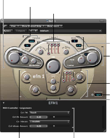
111
EFM1 overview
The 16-voice EFM1 is a simple but powerful frequency modulation synthesizer. It can produce
the rich bell and digital sounds that frequency modulation (FM) synthesis has become
synonymous with.
If you’re new to synthesizers, see Synthesizer basics overview on page 472, which will introduce
you to the terminology and give you an overview of various synthesis systems and how
they work.
Extended parameters
Output parameters
Modulation parameters
Randomize parameters
Output parameters
Carrier parameters
Global parameters
Modulation parameters
Global parameters
Modulator parameters
EFM1 4
Chapter 4 EFM1 112
EFM1 is divided into several areas.
•Global parameters: The top section contains parameters that set the overall tuning of EFM1.
Further controls enable you to set the Glide (portamento) time, limit the number of voices, and
thicken the sound with Unison. See EFM1 global parameters on page 117.
•Modulator and Carrier parameters: The FM engine consists of the modulator and carrier
parameters (raised, darker sections), and the FM Intensity knob (in the center). These are
the key controls for setting the basic tone of EFM1. See Modulator and carrier overview on
page 113 .
•Modulation parameters: The modulation envelope and LFO at the top and bottom of the
mushroom-shaped area in the center respectively are used to animate the sound. See EFM1
modulation parameters on page 116 .
•Output parameters: The bottom section houses the Output section, which includes the Sub
Osc Level and Stereo Detune knobs that can be used to thicken the sound. The volume
envelope, Main Level, and Velocity controls are used to set the EFM1 level. See EFM1 output
parameters on page 118 .
•Randomize parameters: The Randomize eld and button in the lower-right corner are used to
create random variations of the current settings, resulting in new sounds. See Create random
EFM1 sounds on page 119 .
•Extended parameters: Accessed by clicking the disclosure triangle at the lower left of the
interface, these parameters allow you to assign MIDI controllers to the FM Depth and Vibrato
parameters. See EFM1 extended parameters and EFM1 MIDI controller assignments on
page 120 .

Chapter 4 EFM1 113
EFM1 modulator and carrier parameters
Modulator and carrier overview
In FM synthesis, the basic sound is generated by setting dierent tuning ratios between the
modulator and carrier oscillators and by altering the FM intensity. The tuning ratio determines
the basic overtone structure, and FM intensity controls the level of these overtones.
At the core of the EFM1 synthesis system is a multiwave modulator oscillator and a sine wave
carrier oscillator. The basic sine wave of the carrier oscillator is a pure, characterless tone.
To make things more sonically interesting, you use the modulator oscillator to modulate the
frequency of the carrier oscillator. This modulation occurs in the audio range—you can hear it—
and results in a number of new harmonics becoming audible.
The pure sine wave of the carrier oscillator is combined with the newly generated harmonics,
making the sound more interesting.
Changes to the ratio of the two oscillators is achieved by adjusting the Harmonic parameters,
found in both the Modulator and Carrier sections. Additional tuning control is provided by the
Fine (tune) parameters.
FM Intensity knob
Carrier parametersModulator parameters
Chapter 4 EFM1 114
Modulator parameters
•Harmonic knob: Rotate to set the tuning ratio between the modulator (left) and carrier (right)
oscillators. See Set the EFM1 tuning ratio on page 115 .
•Fine (tune) knob: Rotate to adjust the tuning between two adjacent harmonics, as determined
by the Harmonic knobs of both oscillators. The range of this control is ±0.5 harmonic. In the
center (0) position, Fine tune does not have an eect. Click the “0” to center the Fine tune knob.
Depending on the amount of detuning, you will hear one of the following:
•A subtle “beating” of the timbre if lower detuning amounts are used
•New harmonic and inharmonic overtones if high detuning amounts are used
•Wave knob: Rotate to choose a dierent waveform for the modulator oscillator. See Choose a
dierent EFM1 modulator waveform on page 115 .
•FM (Intensity) knob: Rotate to set the amount of carrier oscillator frequency modulation by the
modulator oscillator. As you adjust the FM knob, the intensity—and number—of overtones
increases, making the sound brighter.
Note: Although the technology behind it is very dierent, you could compare the
FM (Intensity) parameter with the Filter Cuto parameter of an analog synthesizer.
Carrier parameters
•Harmonic knob: Rotate to set the tuning ratio between the modulator (left) and carrier (right)
oscillators. See Set the EFM1 tuning ratio on page 115 .
•Fine (tune) knob: Rotate to adjust the tuning between two adjacent harmonics, as determined
by the Harmonic knobs of both oscillators. The range of this control is ±0.5 harmonic. In the
center (0) position, Fine tune does not have an eect. Click the “0” to center the Fine tune knob.
Depending on the amount of detuning, you will hear one of the following:
•A subtle “beating” of the timbre if lower detuning amounts are used
•New harmonic and inharmonic overtones if high detuning amounts are used
•Fixed Carrier button: Turn on to disconnect the carrier frequency from keyboard, pitch bend,
and LFO modulations, thus allowing you to produce a carrier tone that is free of these
modulation sources.
Chapter 4 EFM1 115
Set the EFM1 tuning ratio
The carrier frequency is determined by the played key, and the modulator frequency is typically a
multiple of the carrier frequency.
You can tune the modulator and carrier to any of the rst 32 harmonics. The tuning relationship,
or ratio, between the two signicantly changes the base sound of the EFM1, and is best set
by ear.
You use the Harmonic knobs to set the tuning ratio between the modulator (left) and carrier
(right) oscillators.
In general, even tuning ratios between the carrier and modulator tend to sound more harmonic
or musical, whereas odd ratios produce more inharmonic overtones—which are great for bell
and metallic sounds.
In this respect, you can view the tuning ratio as being somewhat like the waveform selector of
an analog synthesizer.
Note: The Harmonic and Fine tune knobs only aect the tuning relationship between the carrier
and modulator oscillators. These should not be confused with the global Tune and Fine Tune
parameters, which determine the overall tuning of the EFM1 (see EFM1 global parameters on
page 117 ).
Experiment with basic tuning ratios
Do one of the following:
mSet the modulator and carrier to the rst harmonic—a 1:1 ratio.
A sawtooth-like sound is produced.
mSet the modulator to the second harmonic and the carrier to the rst harmonic—a 2:1 ratio.
A tone that sounds similar to a square wave is produced.
Choose a dierent EFM1 modulator waveform
In classic FM synthesis, sine waves are used as modulator and carrier waveforms. The EFM1
modulator oscillator provides a number of additional digital waveforms, which extend its sonic
capabilities signicantly. These waveforms contain additional harmonics that add a new level of
richness to the resulting FM sounds.
Choose a dierent waveform
mTurn the Wave parameter knob.
•If you turn the knob to the full-left position, the modulator produces a sine wave.
•If you turn the knob clockwise, you step—or fade—through a series of complex
digital waveforms.
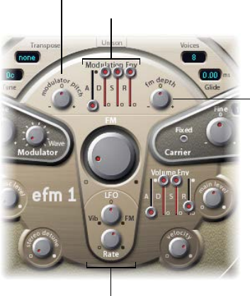
Chapter 4 EFM1 116
EFM1 modulation parameters
FM synthesis is, at its core, caused by the intensity and type of modulations that take place in the
signal path. Therefore, the modulators outlined in this section have a dierent impact and role to
play than equivalent envelopes and LFOs found in analog synthesizer designs.
LFO parameters
FM Depth
Modulation Envelope
Modulator Pitch
Modulation parameters
•Modulation Env(elope) sliders: Control both the FM (Intensity) and Modulator pitch parameters
over time. The envelope is triggered every time a MIDI note is received.
•A(ttack) slider: Sets the time it takes to reach the maximum envelope level.
•D(ecay) slider: Sets the time it takes to reach the Sustain level.
•S(ustain) slider: Sets a level that is held until the MIDI note is released.
•R(elease) slider: Sets the time it takes to reach a level of 0, after the MIDI note has
been released.
•Modulator Pitch knob: Rotate to determine the impact of the modulation envelope on the
pitch of the modulator oscillator.
•If you turn the knob clockwise, you increase the eect of the modulation envelope. If
you turn the knob counterclockwise, you invert the eect of the modulation envelope, as
follows: the envelope slopes down during the attack phase and slopes up during the decay
and release time phases.
•If you click the “0” to center the Modulator Pitch knob, the envelope has no eect on the
pitch of the modulator oscillator.
•FM Depth knob: Rotate to determine the impact of the modulation envelope on FM intensity.
•If you turn the knob clockwise, you increase the eect of the modulation envelope. If
you turn the knob counterclockwise, you invert the eect of the modulation envelope, as
follows: the envelope slopes down during the attack phase and slopes up during the decay
and release time phases.
•If you click the “0” to center the FM Depth knob, the envelope has no eect on FM intensity.
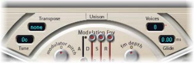
Chapter 4 EFM1 117
•LFO (low frequency oscillator) knob: Rotate to set the amount of modulation applied to
FM intensity or pitch.
•If you turn the LFO knob clockwise, you increase the eect of the LFO on FM Intensity. If you
turn the knob counterclockwise, you introduce a vibrato.
•If you click the “0” to center the LFO knob, the LFO has no eect.
•Rate knob: Rotate to set the speed of the LFO.
EFM1 global parameters
The global parameters are used to set the tuning, number of voices, and other aspects of the
EFM1’s overall sound.
Global parameters
•Transpose pop-up menu: Choose the base pitch. You can transpose EFM1 by semitones or
octaves with this control.
•Tune eld: Drag to ne-tune the pitch of EFM1 by cents. One cent is 1/100th of a semitone.
•Voices pop-up menu: Choose the number of simultaneously playable voices—polyphony. You
can choose mono (one voice), legato (one voice), or any number from 2 to 16 voices.
•In Mono mode, staccato playing retriggers the envelope generators every time a new note
is played. If you play in a legato style (play a new key while holding another), the envelope
generators are triggered only for the rst note you play legato, then they continue their
curve until you release the last legato played key.
•Legato mode is also monophonic, but with one dierence: the envelope generators are
retriggered only if you play staccato—releasing each key before playing a new key. If you
play in a legato style, envelopes are not retriggered.
Note: On several monophonic synthesizers, the behavior in Legato mode is referred to as
single trigger, while Mono mode is referred to as multi trigger.
•Unison button: Turn on to layer two complete EFM1 voices, thus making the sound richer. EFM1
can be played with up to eight-voice polyphony when in unison mode.
•Glide eld: Drag to introduce a continuous pitch bend between two consecutively played
notes. Adjust the Glide value, which is in ms, to determine the time it takes for the pitch to
travel from the last played note to the next.
Note: Glide can be used in both of the monophonic modes—Mono and Legato—or in any of
the polyphonic settings—where Voices is set from 2 to 16.
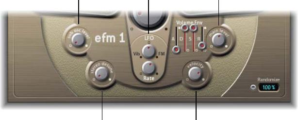
Chapter 4 EFM1 118
EFM1 output parameters
EFM1 provides the following level controls.
Velocity knob
Stereo Detune knob
Main Level knobVolume envelope
Sub Osc Level knob
Output parameters
•Sub Osc Level knob: Rotate to introduce a sub-oscillator signal that enhances bass response.
EFM1 features a sine wave sub-oscillator. This operates one octave below the FM engine, as
determined by the Transpose parameter. Turning up the Sub Osc Level control mixes the sub-
oscillator sine wave with EFM1’s FM engine output.
•Stereo Detune knob: Rotate to add a chorus-like eect to the sound. This is achieved by
doubling the EFM1 voice with a secondary, detuned FM engine. High values result in a wide
stereo eect being added to the detuning, thus increasing the perceived space and width of
your sound.
Note: It is possible that mono compatibility could be lost with use of this parameter.
•Volume Env(elope): Shapes the level of the sound over time. The volume envelope is triggered
every time a MIDI note is received.
•A(ttack) slider: Move to set the time it takes to reach the maximum volume level.
•D(ecay) slider: Move to set the time it takes to reach the Sustain level.
•S(ustain) slider: Move to set a level that is held until the MIDI note is released.
•R(elease) slider: Move to set the time it takes to reach a level of 0, after the MIDI note has
been released.
•Main Level knob: Rotate to set the overall output level of EFM1.
•Velocity knob: Rotate to determine the sensitivity of EFM1 to incoming MIDI velocity messages.
EFM1 dynamically reacts to MIDI velocity messages—harder playing will result in a brighter
and louder sound. Set the Velocity control all the way to the left—counterclockwise—if you
don’t want EFM1 to respond to velocity.

Chapter 4 EFM1 119
Create random EFM1 sounds
The Randomize feature in the lower-right corner of the interface generates new sounds. It does
this by randomly altering a number of key EFM1 parameter values.
This feature is ideal for creating subtle variations of a particular sound or for creating totally new
sounds. It is useful when getting started with FM synthesis.
Randomize parameters
•Randomize button: Creates a new sound by randomizing multiple parameters.
•Randomize eld: Determines the amount of randomization—variance from the original sound.
Create a random sound
mClick the Randomize button.
You can click multiple times. Save your settings as you go if you generate a sound you want
to keep.
Limit the amount of randomization
mDrag in the numeric eld to set the amount of randomization—variance from the original sound.
If you want to only randomly “tweak” the current sound, use values below 10%. Use higher values
to radically change the sound with each click.
EFM1 extended parameters
Click the disclosure triangle at the lower left to open the EFM1 extended parameters.
See EFM1 MIDI controller assignments for information about the controller assignment
extended parameters.
Extended parameters
•MIDI Mono Mode pop-up menu: Choose O, On (with common base channel 1), or On (with
common base channel 16).
In either mode, each voice receives on a dierent MIDI channel. Controllers and MIDI messages
sent on the base channel aect all voices.
•Mono Mode Pitch Range pop-up menu: Choose 0, 24, or 48.
The chosen pitch bend range aects individual note pitch bend messages received on
all but the common base channel. The default is 48 semitones, which is compatible with
Mobile GarageBand's keyboard in pitch mode. When using a MIDI guitar, 24 semitones is the
preferable setting because most guitar to MIDI converters use this range by default.
Chapter 4 EFM1 120
EFM1 MIDI controller assignments
The EFM1 Extended Parameters area allows you remotely control EFM1 with your MIDI controller
keyboard or other MIDI device. You can assign any unused MIDI controller to the following
parameters:
•FM Amount
•Vibrato
Note: EFM1 also responds to MIDI pitch bend data. Pitch bend is hard-wired to the overall pitch
of EFM1.
Assign a MIDI controller
1 Choose the controller name or number from the Ctrl FM or Ctrl Vibrato pop-up menu.
2 Set the FM or vibrato amount using the slider below the pop-up menu.
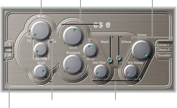
121
ES E overview
The eight-voice ES E (ES Ensemble) synthesizer is ideal for quickly creating warm, rich pad and
ensemble sounds.
ES E produces sounds using subtractive synthesis. It features an oscillator that generates
harmonically rich waveforms. You subtract—cut, or lter out—portions of these waveforms and
reshape them to create new sounds.
If you’re new to synthesizers, see Synthesizer basics overview on page 472, which will introduce
you to the terminology and give you an overview of dierent synthesis methods and how
they work.
Envelope parameters
LFO parameters
Oscillator parameters
Output parameters
Filter parameters
Oscillator
parameters
ES E is divided into several areas.
•Oscillator parameters: The oscillator Wave and Octave parameters are shown in the area to
the left. The oscillator generates the waveforms that form the basis of your sound. See ES E
oscillator parameters on page 122.
•LFO parameters: The LFO parameters (below the Wave knob) are used to modulate the sound.
See ES E LFO parameters on page 123.
•Filter parameters: The section to the right of the oscillator parameters includes the Cuto
(frequency) and Resonance knobs. You use the lter to contour the waveforms sent from the
oscillator. See ES E lter parameters on page 124 .
•Envelope parameters: The area to the right of the lter parameters contains the envelope
parameters, which control the level of the sound over time. See ES E envelope parameters on
page 125.
ES E 5
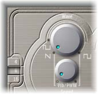
Chapter 5 ES E 122
•Output parameters: The area at the extreme right houses the switches for the integrated
modulation eects and the Volume knob, which is responsible for the main output level. The
eects can be used to color or thicken the sound. See ES E output parameters on page 125.
•Extended parameters: Not shown in the image, the extended parameters are accessed by
clicking the triangle at the lower left of the interface. These parameters include bend and
tuning functions. See Extended ES E parameters on page 126.
ES E oscillator parameters
The synthesizer oscillator generates a waveform, which is then sent to other portions of the
synthesizer engine for processing or manipulation.
Oscillator parameters
•Wave knob: Rotate to select the waveform of the oscillator, which is responsible for the basic
color of the tone. The leftmost setting of the Wave parameter causes the oscillators to output
sawtooth signals. Across the remaining range, the oscillators output pulse waves, with the
average pulse width determined by the Wave parameter position.
•4, 8, and 16 buttons: Switch the pitch in octaves—transpose it up or down. The lowest setting is
16 feet, and the highest is 4 feet. The use of the term feet to determine octaves comes from the
measurements of organ pipe lengths. The longer and wider the pipe, the deeper the tone.
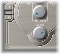
Chapter 5 ES E 123
ES E LFO parameters
The LFO (low frequency oscillator) generates a cyclic waveform that is used to modulate the ES E
waveform. The behavior and eect of the LFO depend on whether a sawtooth or pulse wave
is selected.
•If Wave is set to sawtooth, the LFO modulates the frequency of the waveform, resulting in a
vibrato or siren eect—depending on the LFO speed and intensity.
•If Wave is set to a pulse wave, the LFO modulates the waveform’s pulse width—pulse width
modulation (PWM).
LFO parameters
•Vib(rato)/PWM knob: Rotate to dene the intensity of LFO modulation.
•Speed knob: Rotate to set the frequency of LFO modulation.
Note: When the pulse width becomes very narrow, the signal sounds as if it is being
interrupted—“breaking up.” Given this potential artifact, set the PWM intensity with care, and
select the Wave parameter’s 12 o’clock position (50% rectangular) for the pulse width, if you
want to achieve the maximum modulation range.
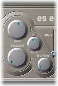
Chapter 5 ES E 124
ES E lter parameters
ES E includes a lowpass lter that lets you contour the output from the oscillator.
Filter parameters
•Cuto knob: Rotate to control the cuto frequency of the lter.
•Resonance knob: Rotate to boost or cut portions of the signal that surround the frequency
dened by the Cuto parameter.
Note: Increasing the Resonance value results in a rejection of bass—low frequency energy—
when using lowpass lters.
•AR Int knob: Rotate to set the amount (depth) of cuto frequency modulation applied by the
envelope generator.
Note: ES E provides one envelope generator per voice, oering Attack and Release (AR)
parameters (see ES E envelope parameters on page 125 ).
•Velo Filter knob: Rotate to set the velocity sensitivity of the cuto frequency modulation
applied by the envelope generator.
Note: This parameter has no eect if AR Int is set to 0.

Chapter 5 ES E 125
ES E envelope parameters
The AR (Attack and Release) envelope aects both the lter cuto (AR Int) and the level of the
sound over time.
Envelope parameters
•Attack slider: Move to set the time it takes for the signal to reach the initial signal level, known
as the sustain level.
•Release slider: Move to set the time it takes for the signal to fall from the sustain level to a level
of 0.
ES E output parameters
The ES E output stage consists of the Volume section and the Chorus/Ensemble buttons.
Output Parameters
•Volume knob: Rotate to set the overall output level.
•Velo Volume knob: Rotate to set the amount (depth) of velocity sensitivity to incoming MIDI
note events. When set to higher values, each note is louder, if struck more rmly. At lower
values, the dynamic response is reduced, so that there is little dierence when you play a note
pianissimo (soft) or forte (loud/hard).
•Chorus I, Chorus II, and Ensemble buttons: Turn these eect variations on or o. If no button is
active, the eects processor is turned o.
•Chorus I is a typical chorus eect.
•Chorus II is characterized by a stronger modulation.
•Ensemble has a fuller and richer sound, due to a more complex modulation routing.
Chapter 5 ES E 126
Extended ES E parameters
ES E oers three additional parameters that are accessed by clicking the disclosure triangle at the
lower left of the interface.
Extended parameters
•Pos. Bender Range: Move to set the positive—upward—pitch bend range in semitone steps.
This allows you to use the pitch bend controller of your keyboard to bend the ES E pitch.
•Neg. Bender Range: Move to set the negative—downward—pitch bend range in semitone
steps, by up to 2 octaves—a value of 24. The default Neg. Bender Range value is Pos PB
(positive pitch bend). In essence, this means that only positive pitch bend is available.
•Tune: Move to tune the instrument sound in cents. A cent is 1/100th of a semitone.
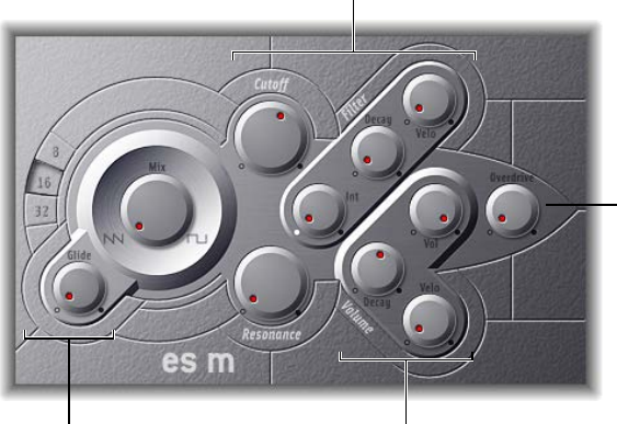
127
ES M overview
The monophonic ES M (ES Mono) synthesizer is a good starting point if you’re looking for bass
sounds that punch through your mix.
ES M features an automatic ngered portamento mode, making bass slides easy. It also provides
an automatic lter compensation circuit that delivers rich, creamy basses, even when you use
higher resonance values.
ES M produces sounds using subtractive synthesis. It has an oscillator that generates
harmonically rich waveforms. You subtract—cut, or lter out—portions of these waveforms and
reshape them to create new sounds.
If you’re new to synthesizers, see Synthesizer basics overview on page 472, which will introduce
you to the terminology and give you an overview of dierent synthesis methods and how
they work.
Output parameters
Oscillator parameters
Overdrive
Filter and Filter Envelope
parameters
ES M is divided into several areas.
•Oscillator parameters: The oscillator Mix and Octave parameters are shown in the area to the
left. The oscillator generates the basic waveforms that form the basis of your sound. See ES M
oscillator parameters on page 128 .
•Filter and lter envelope parameters: The section to the right of the Oscillator parameters
includes the Cuto (frequency) and Resonance knobs. The lter is used to contour the
waveforms sent from the oscillators. The lter envelope parameters are found toward the
upper right. These control the lter cuto over time. See ES M lter and lter envelope on
page 129.
ES M 6

Chapter 6 ES M 128
•Output parameters: The angle-shaped area to the lower right contains the level envelope and
output parameters, which control the level of the sound over time. The Overdrive knob is
located near the right edge of the interface, halfway up. The Overdrive can be used to color or
add bite to the sound. See ES M level envelope and output controls on page 130 .
•Extended parameters: Not shown in the image, the extended parameters are accessed by
clicking the triangle at the lower left of the interface. These parameters include bend and
tuning functions. See Extended ES M parameters on page 130 .
ES M oscillator parameters
The synthesizer oscillator is used to generate a waveform, which is then sent to other portions of
the synthesizer engine for processing or manipulation.
Oscillator parameters
•Mix knob: Rotate to set the waveform of the oscillator, which is responsible for the basic color
of the tone.
•Setting the Wave parameter all the way to the left causes the oscillator to output
sawtooth signals.
•Setting the Wave parameter all the way to the right outputs a 50% rectangular wave, which
is heard one octave below the sawtooth.
•For any Wave setting between these extreme positions, the oscillator outputs a crossfaded
mix of the two waveforms.
•8, 16, and 32 buttons: Switch the pitch in octaves—transpose it up or down. The lowest setting
is 32 feet, and the highest is 8 feet. The use of the term feet to determine octaves comes from
the measurements of organ pipe lengths. The longer and wider the pipe, the deeper the tone.
•Glide knob: Rotate to introduce a continuous pitch bend between two consecutively played
notes. Adjust the Glide value, in ms, to determine the time it takes for the pitch to travel from
the last played note to the next. At a value of 0, no glide eect occurs.
Note: The ES M always works in a ngered portamento mode, with notes played in a legato
style resulting in a glide—portamento—from pitch to pitch.
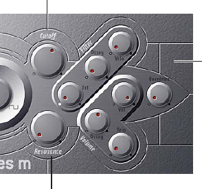
Chapter 6 ES M 129
ES M lter and lter envelope
The ES M includes a lowpass lter that lets you contour the output from the oscillator. The lter
has a dedicated envelope.
Cutoff knob
Resonance knob
Filter envelope
parameters
Filter and lter envelope parameters
•Cuto knob: Rotate to set the cuto frequency of the ES M lter. Its slope is 24 dB/octave.
•Resonance knob: Rotate to boost or cut portions of the signal that surround the frequency
dened by the Cuto parameter.
Note: Increasing the Resonance value results in a rejection of bass—low frequency energy—
when using lowpass lters. The ES M compensates for this side-eect internally, resulting in a
more bassy sound.
•Int knob: Rotate to dene the amount—the intensity or depth—of cuto frequency
modulation applied by the envelope generator.
•Decay knob: Rotate to set the decay time of the lter envelope.
•Velo knob: Rotate to set the velocity sensitivity of the cuto frequency modulation applied by
the envelope generator.
Note: The Decay and Velo parameters have no eect if Int is set to 0.
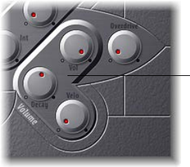
Chapter 6 ES M 130
ES M level envelope and output controls
The output stage of the ES M oers the following parameters.
Level parameters
Envelope and output parameters
•Decay knob: Rotate to set the decay time of the dynamic stage. The attack, release, and sustain
times of the synthesizer are internally set to 0.
•Velo knob: Rotate to determine the velocity sensitivity of the dynamic stage.
•Vol knob: Rotate to set the ES M master output level.
•Overdrive knob: Rotate to set the level of the integrated overdrive eect.
Important: To avoid hurting your ears or damaging your speakers, consider turning down the
Volume level before setting Overdrive to a high value; then turn it up gradually.
Extended ES M parameters
ES M oers three additional parameters that you access by clicking the disclosure triangle at the
lower left of the interface.
Extended parameters
•Pos. Bender Range: Move to set the positive—upward—pitch bend range in semitone steps.
This allows you to use the pitch bend controller of your keyboard to bend the ES M pitch.
•Neg. Bender Range: The default Neg. Bender Range value is Pos PB (positive pitch bend). In
essence, this means that only positive pitch bend is available. Move to set the negative—
downward—pitch bend range in semitone steps, by up to 2 octaves (a value of 24).
•Tune: Move to tune the instrument in cents. One cent is 1/100th of a semitone.
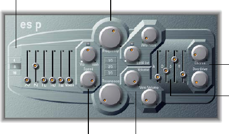
131
ES P overview
The eight-voice ES P (ES Poly) emulates classic polyphonic synthesizers of the 1980s.
It is a versatile instrument that is capable of producing a huge variety of useful musical sounds.
The creation of classic analog synthesizer brass sounds is just one of its many strengths.
ES P produces sounds using subtractive synthesis. It features an oscillator that generates
harmonically rich waveforms. You subtract—cut, or lter out—portions of these waveforms and
reshape them to create new sounds.
If you’re new to synthesizers, see Synthesizer basics overview on page 472, which will introduce
you to the terminology and give you an overview of dierent synthesis methods and how
they work.
Level parametersLFO parameters
Envelope parameters
Effect parameters
Filter parameters
Oscillator parameters
ES P is divided into several areas.
•Oscillator parameters: The oscillator sliders are shown in the area to the left. The octave
parameters are also found in this section. The oscillators generate the basic waveforms that
form the basis of your sound. See ES P oscillator parameters on page 132 .
•LFO parameters: The LFO parameters (to the right of the oscillator parameters) are used to
modulate the sound. See ES P LFO parameters on page 133.
•Filter parameters: The vertical column in the center includes the (cuto) Frequency and
Resonance knobs and the key follow buttons. The lter is used to contour the waveforms sent
from the oscillators. See ES P LFO parameters on page 133.
•Envelope and level parameters: The area to the right of the lter parameters contains the
envelope and level parameters, which control the level of the sound over time. See ES P
envelope and level controls on page 135.
•Eect parameters: The area at the extreme right contains the Chorus and Overdrive parameters.
These can be used to color or thicken the sound. See Integrated ES P eects processor on
page 136.
ES P 7
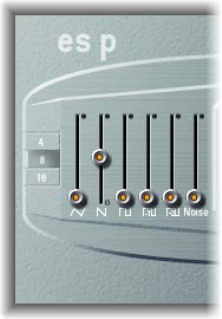
Chapter 7 ES P 132
•Extended parameters: Not shown in the image, the extended parameters are accessed by
clicking the disclosure triangle at the lower left of the interface. These parameters include
bend and tuning functions. See Extended ES P parameters on page 136.
ES P oscillator parameters
ES P features several oscillators that output dierent waveforms. These signals can be mixed
together—at dierent levels—providing countless variations of the raw material used for
your sounds.
In addition to triangular, sawtooth, and rectangular waves, the rectangular waves of two sub-
oscillators are also available. The left sub-oscillator fader is one octave lower than the main
oscillators, and the right sub-oscillator fader is two octaves lower. Use these to fatten up
the sound.
Oscillator parameters
•Triangle oscillator slider: Drag to set the level of the triangle waveform output by the oscillators.
•Sawtooth oscillator slider: Drag to set the level of the sawtooth waveform output by
the oscillators.
•Rectangle oscillator slider: Drag to set the level of the rectangle waveform output by the
oscillators. The pulse width is xed at 50%.
•Sub-oscillator -1 octave slider: Drag to set the level of the (rectangular) sub-oscillator waveform,
which is one octave lower than the main oscillators. Use this to fatten up the sound. The pulse
width is xed at 50%.
•Sub-oscillator - 2 octaves slider: Drag to set the level of the (rectangular) sub-oscillator
waveform, which is two octaves lower than the main oscillators. Use this to fatten up the
sound. The pulse width is xed at 50%.
•Noise generator slider: Drag to set the level of white noise added to the mix. This is the raw
material for classic synthesizer sound eects, such as ocean waves, wind, and helicopters.
•4, 8, and 16 buttons: Switch the pitch in octaves—transpose it up or down. The lowest setting is
16 feet, and the highest is 4 feet. The use of the term feet to determine octaves comes from the
measurements of organ pipe lengths. The longer and wider the pipe, the deeper the tone.
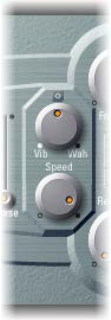
Chapter 7 ES P 133
ES P LFO parameters
ES P features an LFO (low frequency oscillator), which can generate a vibrato or wah eect.
•Modulate the frequency of the oscillators, resulting in a vibrato
•Modulate the cuto frequency of the dynamic lowpass lter, resulting in a wah wah eect
LFO parameters
•Vib/Wah knob: Turn to the left to set a vibrato; turn to the right to cyclically modulate the lter.
•Speed knob: Rotate to set the rate of the vibrato or cuto frequency modulation.
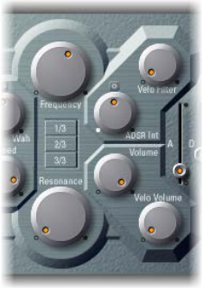
Chapter 7 ES P 134
ES P lter parameters
ES P includes a lowpass lter that lets you contour the output signals from the oscillator.
Filter parameters
•Frequency knob: Rotate to set the cuto frequency of the ES P’s lowpass lter.
•Resonance knob: Rotate to boost or cut portions of the signal that surround the frequency
dened by the Frequency knob.
Note: Increasing the Resonance value results in a rejection of bass—low frequency energy—
when using lowpass lters. The ES P compensates for this side eect internally, resulting in a
more bassy sound.
•1/3, 2/3, and 3/3 (key follow) buttons: The cuto frequency can be modulated by MIDI note
number (keyboard position); you may know this parameter as keyboard follow on other
synthesizers. Click a button to choose 1/3, 2/3, or full-keyboard follow (3/3). If no button is
active, the key you strike won’t aect the cuto frequency. This makes the lower notes sound
relatively brighter than the higher ones. If you choose 3/3, the lter follows the pitch, resulting
in a constant relationship between cuto frequency and pitch. This is typical of many acoustic
instruments where higher notes sound both brighter in tone and higher in pitch.
•ADSR Int knob: Rotate to dene the amount (depth) of cuto frequency modulation applied by
the envelope generator (see ES P envelope and level controls on page 135 ).
•Velo Filter knob: Rotate to set the velocity sensitivity of the cuto frequency modulation
applied by the envelope generator. The main envelope generator (ADSR) modulates the cuto
frequency over the duration of a note. The intensity of this modulation can respond to velocity
information. If you play pianissimo (velocity = 1), the modulation is minimal. If you strike with
the hardest fortissimo (velocity = 127), the modulation is more intense.
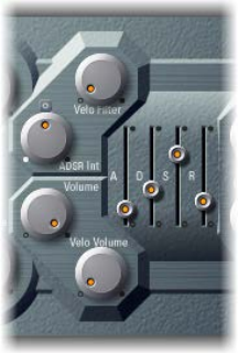
Chapter 7 ES P 135
ES P envelope and level controls
ES P features an ADSR envelope that aects both the lter cuto (ADSR Int) and the level of the
sound over time. This section also covers the master level control parameters.
Envelope and level parameters
•Attack slider: Move to set the time it takes for the signal to reach the initial, desired signal level
(the sustain level).
•Decay slider: Move to set the time it takes for the signal to fall from the attack level to the
sustain level.
•Sustain slider: Move to set the signal level (the sustain level).
•Release slider: Move to set the time it takes for the signal to fall from the sustain level to a level
of zero.
•Volume knob: Rotate to set the overall ES P output level.
•Velo Volume knob: Rotate to set the amount (depth) of velocity sensitivity to incoming MIDI
note events. When set to higher values, each note is louder if struck harder. At lower values, the
dynamic response is reduced, so that there is little dierence when you play a note pianissimo
(soft) or forte (loud/hard).
•VCA Mode buttons (Controls view): Click ADSR to control the amplier with the ADSR envelope
generator. Click Gate to output a constant organ-like tone when a key is played.
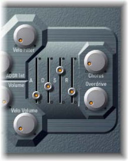
Chapter 7 ES P 136
Integrated ES P eects processor
ES P oers integrated stereo chorus and overdrive eects. These are based on similar eects
processors found in the aordable Japanese synthesizers of the 1980s—which the ES P emulates.
ES P eect parameters
•Chorus knob: Rotate to set the intensity (depth) of the integrated chorus eect.
•Overdrive knob: Rotate to set the overdrive/distortion level of the ES P output.
Important: To avoid hurting your ears or damaging your speakers, consider turning down the
Volume level before setting Overdrive to a high value; then turn it up gradually.
Extended ES P parameters
ES P oers three additional parameters that are accessed by clicking the disclosure triangle at the
lower left of the interface.
•Pos. Bender Range: Move to set the positive—upward—pitch bend range in semitone steps.
This allows you to use the pitch bend controller of your keyboard to bend the ES P pitch.
•Neg. Bender Range: The default Neg. Bender Range value is Pos PB (positive pitch bend). In
essence, this means that only positive pitch bend is available. Move to set the negative—
downward—pitch bend range in semitone steps, by up to 2 octaves (a value of 24).
•Tune eld: Move to tune the instrument in cents. One cent is 1/100th of a semitone.
137
EVOC 20 PolySynth and vocoding
EVOC 20 PolySynth overview
EVOC 20 PolySynth combines a vocoder with a polyphonic synthesizer and can be played in
real time.
It can create classic vocoder sounds, made famous by groups such as Kraftwerk during the 1970s
and 1980s. Vocoding remains popular in current electronic, hip-hop, R & B, and other music styles.
EVOC 20 PolySynth “listens” to an incoming audio signal—typically of a spoken or sung
performance—and imposes the sonic characteristics and level changes of this signal onto the
integrated synthesizer.
When you play notes and chords with your MIDI keyboard, the internal synthesizer “sings” at the
pitches of incoming MIDI notes, but with the articulations—level changes, vowel and consonant
sounds—of the incoming audio signal. This results in the classic “singing robot” or “synthetic
voice” sounds that vocoders are mainly known for.
EVOC 20 PolySynth can also be used as a synthesizer, or it can be used for more subtle eects
processing—such as the creation of relatively natural-sounding vocal harmonies from a solo
voice performance. Not limited to vocal processing, you can also achieve interesting results by
processing other audio material, such as drum or instrument loops.
To use EVOC 20 PolySynth, you need to insert it into the Instrument slot of an instrument
channel strip. You also need to provide an audio signal as the analysis audio source, via a side
chain.
Set up EVOC 20 PolySynth in your host application
1 Insert EVOC 20 PolySynth into the Instrument slot of an instrument channel strip.
2 Choose an input source from the Side Chain pop-up menu in the plug-in header. This can be an
audio track, live input, or bus, depending on the host application.
The EVOC 20 PolySynth is now ready to accept incoming MIDI data and has been assigned to an
input, audio track, or bus—via a side chain.
3 If applicable to your host application and needs, mute the audio track serving as the side-chain
input, start playback, and play your MIDI keyboard.
4 Adjust the volume levels of EVOC 20 PolySynth and the side-chain source—if not muted—to
meet your needs.
5 To further enhance the sound, adjust the knobs, sliders, and other controls, and insert other
eect plug-ins.
EVOC 20 PolySynth 8
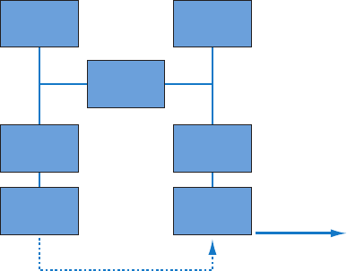
Chapter 8 EVOC 20 PolySynth 138
Vocoder basics
The word vocoder is an abbreviation for voice encoder. A vocoder analyzes and transfers the sonic
character of the audio signal arriving at its analysis input to the synthesizer’s sound generators.
The result of this process is heard at the output of the vocoder.
The classic vocoder sound uses speech as the analysis signal and a synthesizer sound as the
synthesis signal. This sound was popularized in the late 1970s and early 1980s. You may be
familiar with tracks such as “O Superman” by Laurie Anderson, “Funkytown” by Lipps Inc., and
numerous Kraftwerk pieces—such as “Autobahn,” “Europe Endless,” “The Robots,” and “Computer
World.”
In addition to these “singing robot” sounds, vocoding has also been used in many lms—such as
with the Cylons in Battlestar Galactica, and most famously, with the voice of Darth Vader from the
Star Wars saga. See Vocoder history on page 155.
Vocoding, as a process, is not strictly limited to vocal performances. You could use a drum loop as
the analysis signal to shape a string ensemble sound arriving at the synthesis input.
The speech analyzer and synthesizer features of a vocoder are two bandpass lter banks.
Bandpass lters allow a frequency band—a slice in the overall frequency spectrum—to pass
through unchanged. Frequencies that fall outside the band are cut.
In the EVOC 20 plug-ins, these lter banks are named the analysis and synthesis banks. Each lter
bank has a matching number of corresponding bands—if the analysis lter bank has ve bands
(1, 2, 3, 4, and 5), there will be a corresponding set of ve bands in the synthesis lter bank. Band
1 in the analysis bank is matched to band 1 in the synthesis bank, band 2 to band 2, and so on.
The audio signal arriving at the analysis input passes through the analysis lter bank, where it is
divided into bands.
An envelope follower is coupled to each lter band. The envelope follower of each band tracks,
or follows, volume changes in the audio source—or, more specically, the portion of the audio
that has been allowed to pass by the associated bandpass lter. In this way, the envelope
follower of each band generates dynamic control signals.
These control signals are then sent to the synthesis lter bank—where they control the levels of
the corresponding synthesis lter bands. This is done with voltage-controlled ampliers (VCAs)
in analog vocoders. Volume changes to the bands in the analysis lter bank are imposed on the
matching bands in the synthesis lter bank. These lter level changes are heard as a synthetic
reproduction of the original input signal—or a mix of the two lter bank signals.
Analysis
audio source
Synthesis
audio source
Analysis
filter bank
band 1–5
Synthesis
filter bank
band 1–5
Envelope
follower
1–5
VCA
1–5
Control signal 1–5
Audio output
U/V
detection
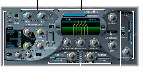
Chapter 8 EVOC 20 PolySynth 139
The more bands a vocoder oers, the more precisely the original sound’s character will be
reproduced by the synthesis lter bank. EVOC 20 PolySynth provides up to 20 bands per
bank. See EVOC 20 block diagram on page 156 for a detailed image of the EVOC 20 PolySynth
signal path.
EVOC 20 PolySynth interface
The EVOC 20 PolySynth interface is divided into six main parameter sections.
U/V Detection parameters
Modulation parameters
Synthesis parameters
Output parameters
Formant Filter
parameters
Sidechain Analysis
parameters
•Sidechain Analysis parameters: Determine how the input signal is analyzed and used by the
EVOC 20 PolySynth. See EVOC 20 PolySynth analysis parameters on page 140.
•U/V Detection parameters: Detect the unvoiced portions of the sound in the analysis signal,
improving speech intelligibility. See EVOC 20 PolySynth (U/V) detection parameters on
page 141.
•Synthesis parameters: Control the polyphonic synthesizer of the EVOC 20 PolySynth. See
EVOC 20 PolySynth synthesis parameters overview on page 143.
•Formant Filter parameters: Congure the analysis and synthesis lter banks. See EVOC 20
PolySynth formant lter on page 149.
•Modulation parameters: Modulate the synthesizer and lter banks—through two LFOs. See
EVOC 20 PolySynth modulation parameters on page 151.
•Output parameters: Congure the output signal of the EVOC 20 PolySynth. See EVOC 20
PolySynth output parameters on page 152.
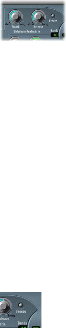
Chapter 8 EVOC 20 PolySynth 140
EVOC 20 PolySynth analysis parameters
The parameters in the Sidechain Analysis section control how EVOC 20 PolySynth analyzes
and uses the input signal. Be precise with these parameters to attain the best possible speech
intelligibility and the most accurate tracking.
Sidechain analysis parameters
•Attack knob: Rotate to determine how quickly each envelope follower—coupled to each
analysis lter band—reacts to rising signal levels. Longer attack times result in a slower
tracking response to transients—level spikes—of the analysis input signal. A long attack time
on percussive input signals—a spoken word or hi-hat part, for example—will translate into
a less articulated vocoder eect. Set the Attack parameter to the lowest possible value to
enhance articulation.
•Release knob: Rotate to determine how quickly each envelope follower—coupled to each
analysis lter band—reacts to falling signal levels. Longer release times cause the analysis
input signal transients to sustain for a longer period at the vocoder’s output. A long release
time on percussive input signals—a spoken word or hi-hat part, for example—will translate
into a less articulated vocoder eect. Use of extremely short release times results in rough,
grainy vocoder sounds. Release values of around 8 to 10 milliseconds are useful starting points.
•Freeze button: Turn on to hold—or freeze—the current analysis sound spectrum indenitely.
When Freeze is enabled, the analysis lter bank ignores the input source, and the Attack and
Release knobs have no eect.
•Bands eld: Drag to set the number—up to 20—of frequency bands used by the lter banks.
Freeze the input signal
Freezing the input signal lets you capture a particular characteristic of the signal, which is then
imposed as a complex sustained lter shape on the Synthesis section. Here are some examples
of when this could be useful:
•If you are using a spoken word pattern as a source, the Freeze button could capture the attack
or tail phase of an individual word within the pattern—the vowel a, for example.
•People cannot sustain sung notes indenitely. To compensate for this human limitation,
use the Freeze button. If the synthesis signal needs to be sustained but the analysis source
signal—a vocal part—is not sustained, use the Freeze button to lock the current formant
levels of a sung note, even during gaps in the vocal part, between words in a vocal phrase. The
Freeze parameter can be automated, which may be useful in this situation.
mClick the Freeze button to hold, or sustain, the sound spectrum of the analysis input signal.
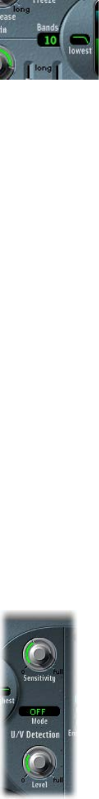
Chapter 8 EVOC 20 PolySynth 141
Set the number of lter bank bands
mTo set the number of frequency bands the EVOC 20 PolySynth’s lter bank uses, drag the Bands
eld vertically.
The greater the number of frequency bands, the more precisely the sound can be reshaped. As
the number of bands is reduced, the source signal’s frequency range is divided up into fewer
bands, and the resulting sound is formed with less precision by the synthesis engine. You may
nd that a good compromise between sonic precision—allowing incoming signals such as
speech and vocals to remain intelligible—and resource usage is around 10 to 15 bands.
EVOC 20 PolySynth (U/V) detection parameters
Human speech consists of a series of voiced sounds—tonal sounds or formants—and unvoiced
sounds. The main distinction between voiced and unvoiced sounds is that voiced sounds
are produced by an oscillation of the vocal cords, whereas unvoiced sounds are produced by
blocking and restricting the air ow with lips, tongue, palate, throat, and larynx.
If speech containing voiced and unvoiced sounds is used as a vocoder’s analysis signal but the
synthesis engine doesn’t dierentiate between voiced and unvoiced sounds, the result sounds
rather weak. To avoid this problem, the synthesis section of the vocoder must produce dierent
sounds for the voiced and unvoiced parts of the signal.
The EVOC 20 PolySynth includes an Unvoiced/Voiced detector for this specic purpose. This
unit detects the unvoiced portions of the sound in the analysis signal and then substitutes
the corresponding portions in the synthesis signal with noise, with a mixture of noise and
synthesizer signal, or with the original signal. If the U/V detector detects voiced parts, it passes
this information to the Synthesis section, which uses the normal synthesis signal for these
portions.
A formant is a peak in the frequency spectrum of a sound. In the context of human voices,
formants are the key component that enables humans to distinguish between dierent vowel
sounds—based purely on the frequency of the sounds. Formants in human speech and singing
are produced by the vocal tract, with most vowel sounds containing four or more formants.
Chapter 8 EVOC 20 PolySynth 142
U/V detection parameters
•Sensitivity knob: Rotate to determine how responsive U/V detection is. Turn to the right for
higher settings, where more of the individual unvoiced portions of the input signal are
recognized. When high settings are used, the increased sensitivity to unvoiced signals can
lead to the U/V sound source being used on the majority of the input signal, including voiced
signals. Sonically, this results in a sound that resembles a radio signal that is breaking up and
contains a lot of static, or noise. (The U/V sound source is determined by the U/V Source menu,
as described below.)
•U/V Source pop-up menu: Choose the sound sources that are used to replace the unvoiced
content of the input signal.
•Noise: Uses noise alone for the unvoiced portions of the sound.
•Noise + Synth: Uses noise and the synthesizer for the unvoiced portions of the sound.
•Blend: Uses the analysis signal after it has passed through a highpass lter for the unvoiced
portions of the sound. The Sensitivity parameter has no eect when this setting is used.
•U/V Level knob: Rotate to set the volume of the signal used to replace the unvoiced content in
the input signal.
Important: Take care with the Level knob, particularly when a high Sensitivity value is used, to
avoid internally overloading the EVOC 20 PolySynth.
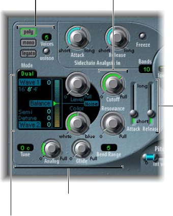
Chapter 8 EVOC 20 PolySynth 143
EVOC 20 PolySynth synthesis parameters
EVOC 20 PolySynth synthesis parameters overview
EVOC 20 PolySynth is equipped with a polyphonic synthesizer that is capable of accepting MIDI
note input. The parameters of the Synthesis section are described below.
Tuning and Pitch
parameters
Oscillator parameters
Envelope parameters
Filter parameters
Global parameters
Synthesis parameters
•Oscillator parameters: Determine the basic waveforms for the synthesis engine of the EVOC 20
PolySynth. See EVOC 20 PolySynth oscillators overview on page 144.
•Tuning and Pitch parameters: Control the overall tuning of the synthesizer, and aspects such as
pitch bend and portamento. See EVOC 20 PolySynth tuning and pitch parameters on page 146.
•Filter parameters: Shape the basic waveforms of the oscillators. See EVOC 20 PolySynth lter
parameters on page 147.
•Envelope parameters: Control the level of the attack and release phases of the synthesizer
sound. See EVOC 20 PolySynth envelope parameters on page 147.
•Global parameters: Determine the keyboard mode and number of voices used by the EVOC 20
PolySynth. (The Global parameters are located at the top left of the interface.) See EVOC 20
PolySynth global parameters on page 148.
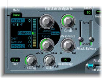
Chapter 8 EVOC 20 PolySynth 144
EVOC 20 PolySynth oscillator parameters
EVOC 20 PolySynth oscillators overview
EVOC 20 PolySynth has two oscillators, which you can switch between Dual mode and FM mode.
The Synthesis section also incorporates a noise generator that can add a further color to
your sound.
Click here to switch
between Dual and FM
mode.
•Dual mode: Each oscillator allows you to choose a digital waveform.
•FM mode: Oscillator 1 generates a sine wave. The frequency, or pitch, of oscillator 1 is
modulated by oscillator 2. This leads to a number of dierent tones and harmonics becoming
audible. Oscillator 2 can use any available digital waveform. See Frequency modulation (FM)
synthesis on page 493).
Each mode subtly changes the parameters shown in the oscillator section.
Both Dual and FM mode provide the following common parameters.
Common oscillator parameters
•16', 8', 4' value buttons: Click to set the octave range for oscillator 1. 16' (16 feet) is the lowest,
and 4' the highest setting. The use of the term feet to determine octaves comes from the
measurements of organ pipe lengths. The longer and wider the pipe, the deeper the tone.
•Wave 1 and Wave 2 elds: Choose the waveform type for oscillators 1 and 2. There are 50 single-
cycle digital waveforms with dierent sonic characteristics.
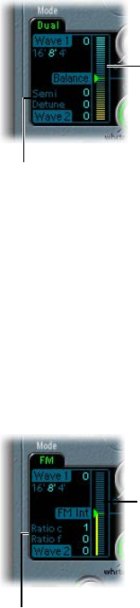
Chapter 8 EVOC 20 PolySynth 145
EVOC 20 PolySynth oscillator dual mode
In dual mode, each oscillator can use any of 50 digital waveforms.
Semi and Detune
parameters are shown in
Dual mode.
Balance slider
Dual mode oscillator parameters
•Semi eld: Drag to adjust the tuning of oscillator 2 in semitone steps.
•Detune eld: Drag to ne-tune both oscillators in cents. One hundred cents equals one
semitone step.
•Balance slider: Drag to set the level balance between the two oscillator signals.
EVOC 20 PolySynth oscillator FM mode
In FM mode, oscillator 1 generates a sine wave. The Wave 1 parameter has no eect in this mode.
Coarse and fine Ratio
parameters are shown in
FM mode.
FM Int slider
FM mode oscillator parameters
•Ratio c(oarse) eld: Drag to adjust the frequency ratio between oscillator 2 and oscillator 1 in
semitone steps.
•Ratio f(ine) eld: Drag to adjust the frequency ratio between oscillator 2 and oscillator 1 in
cents. One hundred cents equals one semitone step.
•FM Int slider: Drag to determine the intensity of modulation. Higher values result in a more
complex waveform with more overtones.

Chapter 8 EVOC 20 PolySynth 146
EVOC 20 PolySynth noise generator
The noise generator provides a further sound source that can be used alongside the
two oscillators.
Important: The noise generator in the oscillator section is independent of the noise generator in
the U/V detection area. For further information about voiced and unvoiced signals, see EVOC 20
PolySynth (U/V) detection parameters on page 141.
Noise generator parameters
•Level knob: Rotate to control the amount of noise added to the signals of the two oscillators.
•Color knob: Rotate to set the timbre of the noise signal. Turn full-left to hear white noise. Turn
full-right to hear blue noise (high-passed noise). White noise has traditionally been used to
create wind and rain sound eects. It has the same energy in each frequency interval. Blue
noise sounds brighter, because its bass portion is suppressed by a highpass lter.
Tip: Set Color to the full-right position and Level to a very low value to achieve a lively and
fresh synthesis signal.
EVOC 20 PolySynth tuning and pitch parameters
The parameters at the lower left of the interface are used to control the overall tuning and other
pitch-related aspects of the EVOC 20 PolySynth sound.
Tuning and pitch parameters
•Tune eld: Drag to set the overall tuning of the EVOC 20 PolySynth, in cents. One hundred cents
equals one semitone step.
•Analog knob: Rotate to set the amount of random pitch detuning. Analog simulates the
instability of analog circuitry found in vintage vocoders by randomly altering the pitch of each
note. This behavior is much like that of polyphonic analog synthesizers.
•Glide knob: Determines the time it takes for the pitch to slide from one note to another—
portamento. Also see EVOC 20 PolySynth global parameters on page 148 for information about
mono and legato mode.
•Bend Range eld: Drag to determine the pitch bend modulation range, in semitone steps.
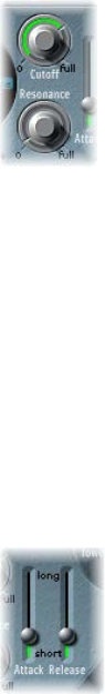
Chapter 8 EVOC 20 PolySynth 147
EVOC 20 PolySynth lter parameters
The Synthesis section includes a lowpass lter that is used for coarse signal shaping, before the
signal is more precisely shaped by the individual bands of the formant lter banks.
Filter parameters
•Cuto knob: Rotate to set the cuto frequency of the lowpass lter. Turn to the left to remove
high-frequency content from the synthesizer signal.
•Resonance knob: Rotate to boost or cut the signal portion that surrounds the frequency
dened by the Cuto knob.
Tip: Set cuto as high as possible, then adjust resonance to achieve a brighter high-end signal.
This is useful for achieving better speech intelligibility.
EVOC 20 PolySynth envelope parameters
EVOC 20 PolySynth includes an Attack/Release envelope generator that controls the levels of the
oscillators over time.
Envelope parameters
•Attack slider: Drag to set the time it takes for the oscillators to reach their maximum level.
•Release slider: Drag to set the time it takes for the oscillators to reach their minimum level, after
the keys have been released.

Chapter 8 EVOC 20 PolySynth 148
EVOC 20 PolySynth global parameters
The parameters at the top left of the interface determine the keyboard mode and number of
voices used by EVOC 20 PolySynth.
Global parameters
•Poly/Mono/Legato buttons: Click a button to determine the keyboard mode.
•When Poly is on, you can set the maximum number of voices in the Voices eld. (When
Mono or Legato is on, a single voice is heard.)
•When Mono is on, Glide is always active and the envelopes are retriggered by every note
played (multi trigger behavior).
•When Legato is on, Glide is active only on tied notes. Envelopes are not retriggered when
tied notes are played (single trigger behavior). (See EVOC 20 PolySynth tuning and pitch
parameters on page 146.)
•Voices eld: Drag to set the maximum number of voices in the numeric eld (only when Poly is
turned on).
•Unison button: Click to turn Unison mode on or o.
•In Unison/Poly mode—where both the Unison and Poly buttons are active—each voice is
doubled. This cuts polyphony in half (to a maximum of eight voices, shown in the Voices
eld). The doubled voices are detuned by the amount dened with the Analog knob.
•In Unison/Mono mode—where both the Unison and Mono or Legato buttons are active—
up to 16 voices can be stacked and played monophonically. The Voices eld displays the
number of stacked voices that are heard.
Important: Stacking voices in Unison/Mono mode increases the output volume. To avoid
overloading the instrument channel strip output, set a low Level slider value and gradually
increase it. See EVOC 20 PolySynth output parameters on page 152 .
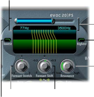
Chapter 8 EVOC 20 PolySynth 149
EVOC 20 PolySynth formant lter
EVOC 20 PolySynth features two formant lter banks—one for the Analysis section and one
for the Synthesis section. Each bank provides up to 20 individual lters. The entire frequency
spectrum of an incoming signal is analyzed by the Analysis section and is divided equally into a
number of frequency bands. These analysis lter bands are mirrored by a corresponding number
of bands in the synthesis lter bank. Each lter bank controls the peak levels—the formants—
within these frequency bands.
The Formant Filter display is divided in two by a horizontal line. The upper half applies to the
Analysis section and the lower half to the Synthesis section. Parameter changes are instantly
reected in the Formant Filter display, thus providing invaluable feedback about what is
happening to the signal as it is routed through the two formant lter banks.
Formant Shift knob
Formant Stretch knob
Lowest button
Resonance knob
Highest button
High Frequency
parameters
Low Frequency
parameters
Formant lter parameters
•Low and High Frequency parameters: Drag to set the lowest and highest frequencies allowed to
pass by the formant lter. Frequencies outside these boundaries are cut.
•The length of the horizontal blue bar at the top represents the frequency range for both
analysis and synthesis (unless Formant Stretch or Formant Shift is used). You can move the
entire frequency range by dragging the blue bar. The silver handles on either end of the blue
bar set the Low Frequency and High Frequency values, respectively.
•You can also drag vertically in the numeric elds to adjust the Low and High
frequency values.
•Lowest and Highest buttons: Click to determine whether the lowest and highest lter bands act
as bandpass lters or whether they act as lowpass or highpass lters.
•Lowest button: Determines whether the lowest lter band acts as a bandpass or highpass
lter. In bandpass mode, the frequencies above and below the lowest band are ignored. In
highpass mode, all frequencies below the lowest band are ltered.
•Highest button: Determines whether the lowest lter band acts as a bandpass or lowpass
lter. In bandpass mode, the frequencies above and below the highest band are ignored. In
lowpass mode, all frequencies above the highest band are ltered.
•Resonance knob: Rotate to determine the basic sonic character of the vocoder. Low settings
result in a softer character; high settings result in a sharper character. Technically, increasing
the Resonance value emphasizes the middle frequency of each frequency band.
Chapter 8 EVOC 20 PolySynth 150
•Formant Stretch knob: Rotate to change the width and distribution of all bands in the synthesis
lter bank. This can be a broader or narrower frequency range than that dened by the Low
and High Frequency parameters.
•When Formant Stretch is set to 0, the width and distribution of the bands in the synthesis
lter bank match the width of the bands in the analysis lter bank. Low values narrow the
width of each band in the synthesis lter bank, whereas high values widen the bands. The
control range is expressed as a ratio of the overall bandwidth.
•Formant Shift knob: Rotate to move all bands in the synthesis lter bank up or down the
frequency spectrum.
•When Formant Shift is set to 0, the positions of the bands in the synthesis lter bank match
the positions of the bands in the analysis lter bank. Positive values move the synthesis lter
bank bands up in frequency, whereas negative values move them down—in respect to the
analysis lter bank band positions.
When combined, Formant Stretch and Formant Shift alter the formant structure of the resulting
vocoder sound, which can lead to interesting timbral changes. For example, using speech signals
and tuning Formant Shift up results in “Mickey Mouse” eects.
Formant Stretch and Formant Shift are also useful if the frequency spectrum of the synthesis
signal does not complement the frequency spectrum of the analysis signal. You could create a
synthesis signal in the high-frequency range from an analysis signal that mainly modulates the
sound in a lower-frequency range, for example.
Note: The use of the Formant Stretch and the Formant Shift parameters can result in the
generation of unusual resonant frequencies when high Resonance settings are used.
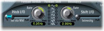
Chapter 8 EVOC 20 PolySynth 151
EVOC 20 PolySynth modulation parameters
The Modulation section contains two LFOs that can either run freely or be synchronized with the
host application tempo.
•The Pitch LFO controls pitch modulation of the oscillators, enabling you to produce
vibrato eects.
•The Shift LFO controls the Formant Shift parameter of the synthesis lter bank, enabling you
to produce dynamic phasing-like eects.
Modulation parameters
•Int via Whl slider: Drag to set the intensity of LFO pitch modulation. The right half of the slider
determines the intensity when the modulation wheel is set to its maximum value; the left
half determines the intensity when the wheel is set to its minimum value. By dragging the
area between the two slider segments, you can simultaneously move both. This parameter
is permanently assigned to the modulation wheel of your MIDI keyboard, or corresponding
MIDI data.
•Rate knobs: Rotate to set the speed of modulation. Values to the left (of the centered position)
are synchronized with the host application tempo. These include bar values, triplet values, and
so on. Values to the right (of the centered position) are nonsynchronized, and are displayed in
Hertz—cycles per second.
Note: The ability to use synchronous bar values could be used to perform a formant shift
every four bars on a cycled one-bar percussion part, for example. Alternatively, you could
perform the same formant shift on every eighth-note triplet within the same part. Either
method can generate interesting results and lead to new ideas, or add life to existing
audio material.
•Waveform buttons: Click to set the waveform type used by the Pitch LFO (left column) or the
Shift LFO (right column). You can choose from the following waveforms for each LFO:
•Triangle
•Falling and rising sawtooth
•Square up and down around zero (bipolar, good for trills)
•Square up from zero (unipolar, good for changing between two denable pitches)
•Random stepped waveform (S & H)
•Smoothed random waveform
•Intensity slider: Drag to dene the amount of formant shift modulation by the Shift LFO.
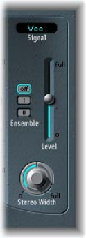
Chapter 8 EVOC 20 PolySynth 152
EVOC 20 PolySynth output parameters
The Output section provides control over the type of signal, stereo width, and level of signal that
is sent from EVOC 20 PolySynth. The Output section also has an ensemble eect processor.
Output parameters
•Signal pop-up menu: Choose the signal that is sent to the EVOC 20 PolySynth main outputs.
•Voc(oder): Choose to hear the vocoder eect.
•Syn(thesis): Choose to hear only the synthesizer signal.
•Ana(lysis): Choose to hear only the analysis signal.
Note: The last two settings are mainly useful for monitoring purposes.
•Ensemble buttons: Turn the ensemble eect on or o and determine the type of sound.
•O: Click to turn the ensemble eect o.
•I: Click to obtain a special chorus eect.
•II: Click to obtain a fuller and richer sound.
•Level slider: Drag to set the overall volume of the EVOC 20 PolySynth output signal.
•Stereo Width knob: Rotate to distribute the output signals of the Synthesis section lter bands
in the stereo eld.
•At the 0 position to the left, the outputs of all bands are centered.
•At the centered position, the outputs of all bands ascend from left to right.
•At the Full position to the right, the bands are output—alternately—to the left and
right channels.
Chapter 8 EVOC 20 PolySynth 153
EVOC 20 PolySynth performance tips
Level and frequency tips
A vocoder always generates the intersection point of the analysis and synthesis signals. If there’s
no treble portion in the analysis signal, the resulting vocoder output also lacks treble. This is also
the case when the synthesis signal has a lot of high-frequency content. Because this is true of
each frequency band, the vocoder demands a stable level in all frequency bands from both input
signals to obtain the best results.
Achieving a great “classic” vocoder eect requires both the analysis and synthesis signals to be
of excellent quality, and it also requires care to be taken with the vocoder parameters. These tips
will help you achieve the best possible results.
•The less the level changes, the better the intelligibility of the vocoder. You should therefore
compress the analysis signal in most cases.
•Due to the way human hearing works, the intelligibility of speech is highly dependent on
the presence of high-frequency content. To aid in keeping speech clear, consider using
equalization to boost or cut particular frequencies in analysis signals before you process them.
•If the analysis signal consists of vocals or speech, a simple shelving lter should be sucient
to boost the high-mid and treble range, which is important for speech intelligibility.
•If the synthesis signal lacks treble energy, it can be generated with a distortion eect. The
Overdrive eect is perfect for this purpose.
Tips to avoid sonic artifacts
A common problem with vocoder sounds involves sudden signal interruptions—ripping,
breaking sounds—and rapidly triggered noises during speech pauses.
The Release parameter denes the time it takes for a given synthesis frequency band to
decrease in level if the signal level of the respective analysis band decreases abruptly. The
sound is smoother when band levels decrease slowly. To achieve this smoother character, use
higher Release values in the Analysis section. Take care to avoid setting an over-long release
time, because this can result in a less distinct, washy sound. Use short Attack values when a fast
reaction to incoming signals is required.
If the analysis signal is compressed as recommended, the level of breath, rumble, and
background noise will rise. These unwanted signals can cause the vocoder bands to open
unintentionally. To eliminate these artifacts, use a noise gate before using compression and
boosting the treble frequencies. If the analysis signal is gated appropriately, you may be able to
reduce the (Analysis) Release value.

Chapter 8 EVOC 20 PolySynth 154
When you gate speech and vocals with the Noise Gate plug-in, use Threshold to dene the level
above which the gate will open, and use Hysteresis to dene a lower Threshold level below
which the gate will close. The Hysteresis value is relative to the Threshold level.
The gure above shows a Threshold setting that is well-suited for speech compression.
Unwanted triggering by low or high frequency noise is avoided by the dedicated sidechain lters
of the Noise Gate plug-in. The Hold, Release, and Hysteresis values are suitable for most vocal and
speech signals.
Tips to enhance speech intelligibility
Keep these points in mind to achieve the best possible speech intelligibility:
•The spectra of the analysis and synthesis signals should almost completely overlap. Coupling
low male voices with synthesis signals in the treble range doesn’t work well.
•The synthesis signal must be constantly sustained, without breaks. The incoming side-chain
signal should be played or sung legato, because breaks in the synthesis signal stop the
vocoder’s output. Alternatively, the Release parameter of the synthesis signal—not the Release
time of the Analysis section—can be set to a longer time. You can also achieve nice eects by
using a reverberation signal as a synthesis signal. Note that the two latter methods can lead to
harmonic overlaps.
•Do not overdrive the vocoder. This can happen easily, and distortion will occur.
•Enunciate your speech clearly if the recording is to be used as an analysis signal. Spoken words
with a relatively low pitch work better than sung vocals—even if the creation of vocoder
choirs is your goal. Pronounce consonants well, as exemplied in the rolled “R” of “We are the
Robots,” by Kraftwerk, a classic vocoder track. This exaggerated pronunciation was specically
made to cater to the vocoder.
•You can freely set Formant parameters. Shifting, stretching, or compressing the formants has
a minimal eect on the intelligibility of speech, as does the number of frequency bands. The
reason for this is due to the human ability to dierentiate the voices of children, women, and
men, whose skulls and throats vary. Such physical dierences cause variations in the formants
that make up their voices. Human perception, or recognition, of speech is based on an analysis
of the relationships between these formants. In the EVOC 20 plug-ins, these relationships are
maintained even when extreme formant settings are used.
Chapter 8 EVOC 20 PolySynth 155
Vocoder history
The development of the vocoder dates back to the 1930s in the telecommunications industry.
Homer Dudley, a research physicist at Bell Laboratories in New Jersey, developed the vocoder
(short for voice encoder) as a research machine. It was originally designed to test compression
schemes for the secure transmission of voice signals over copper phone lines.
It was a composite device consisting of an analyzer and an articial voice synthesizer, as follows:
•Parallel bandpass vocoder: A speech analyzer and resynthesizer.
•Vocoder speech synthesizer: A voice modeler, this valve-driven machine was played by a human
operator. It had two keyboards, buttons to recreate consonants, a pedal for oscillator frequency
control, and a wrist-bar to switch vowel sounds on and o.
The analyzer detected the energy levels of successive sound samples, measured over the entire
audio frequency spectrum via a series of narrow band lters. The results of this analysis could be
viewed graphically as functions of frequency against time.
The synthesizer reversed the process by scanning the data from the analyzer and supplying
the results to a number of analytical lters, hooked up to a noise generator. This combination
produced sounds.
In World War II, the vocoder (known then as the voice encoder) proved to be of crucial
importance, scrambling the transoceanic conversations between Winston Churchill and Franklin
Delano Roosevelt.
Werner Meyer-Eppler, the director of Phonetics at Bonn University, recognized the relevance of
the machines to electronic music—following a visit by Dudley in 1948. Meyer-Eppler used the
vocoder as a basis for his future writings which, in turn, became the inspiration for the German
“Elektronische Musik” movement.
In the 1950s, a handful of recordings ensued.
In 1960, the Siemens Synthesizer was developed in Munich. Among its many oscillators and
lters, it included a valve-based vocoding circuit.
In 1967, a company called Sylvania created a number of digital machines that used time-based
analysis of input signals, rather than bandpass lter analysis.
In 1971, after studying Dudley’s unit, Bob Moog and Wendy Carlos modied a number of
synthesizer modules to create their own vocoder for the Clockwork Orange soundtrack.
Peter Zinovie’s London-based company EMS developed a standalone—and altogether more
portable—vocoder. EMS is probably best known for the Synthi AKS and VCS3 synthesizers. The
EMS Studio Vocoder was the world’s rst commercially available machine, released in 1976. It was
later renamed the EMS 5000. Among its users were Stevie Wonder and Kraftwerk. Stockhausen,
the German “Elektronische Musik” pioneer, also used an EMS vocoder.
Sennheiser released the VMS 201 in 1977, and EMS released the EMS 2000, which was a cut-down
version of its older sibling.
1978 saw the beginning of mainstream vocoder use, riding on the back of popularity created
through the music of Herbie Hancock, Kraftwerk, and a handful of other artists. Among the
manufacturers who jumped into vocoder production at this time are Synton/Bode, Electro-
Harmonix, and Korg, with the VC-10.
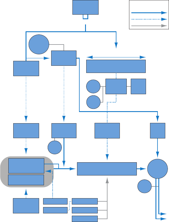
Chapter 8 EVOC 20 PolySynth 156
In 1979, Roland released the VP 330 ensemble/vocoder keyboard.
The late 1970s and early 1980s were the heyday of the vocoder. Artists who used them included
ELO, Pink Floyd, Eurythmics, Tangerine Dream, Telex, David Bowie, Kate Bush, and many more.
On the production side, vocoders could—and can still—be picked up cheaply in the form of kits
from electronics stores.
From 1980 to the present, EMS in the UK, Synton in Holland, and PAiA in the USA have been—
and remain—the main yers of the vocoding ag.
In 1996, Doepfer in Germany and Music and More joined the vocoder-producing fraternity.
From the late 1990s to the present, a number of standalone and integrated software-based
vocoders—like the EVOC 20—have appeared.
EVOC 20 block diagram
This block diagram illustrates the signal path in EVOC 20 TrackOscillator and EVOC 20 PolySynth.
Analysis
source
Track
------------
Side chain
LR
Stereo to mono
TO:
pitch analysis
Sensitivity
TO:
Max/Quant./
Glide
Analysis section
Synthesis section
U/V
detection
PS:
MIDI
keyboard
Noise,
N + Synth
Synthesis
source
EVOC20 PS:
Poly synth
pitch
Level
Frequency range between highest/lowest
1-5
Envelope
follower
1-5
A
B
Freeze
Stretch
Resonance
Shift
Filter bank with five bands
(example)
Level
Stereo
width
L
R
Filter bank
input
Filter bank with five bands
(example)
Voltage-
controlled
Oscillator 1-5
LFO
EVOC20 TO:
Tracking oscillator
Track or side chain
Blend
LFO
Parameter control
Legend
Audio signal
Control signal
157
EXS24 mkII overview
EXS24 mkII is a software sampler. It plays back audio les, called samples, that you load into
it. These samples are combined into tuned, organized collections called sampler instruments.
Because sampler instruments are based on audio recordings, they are ideally suited to emulating
real instruments such as guitars, pianos, and drums.
EXS24 mkII lets you play, edit, and create sampler instruments. You can assign the samples in
sampler instruments to specic key and velocity ranges and process them with EXS24 mkII lters
and modulators.
EXS24 mkII oers powerful modulation and editing features and is a exible synthesizer in
its own right. This enables you to create expressive sounds by using any sample as a basic
synthesizer waveform.
EXS24 mkII can be used as a mono or stereo instrument, or you can route loaded samples to
multiple audio outputs. This enables you to independently process individual drum sounds in a
drum kit, for example.
You can use samples of almost unlimited length in EXS24 mkII by streaming them directly from a
hard disk. This lets you use many of the multigigabyte sample libraries available.
EXS24 mkII provides an extensive library of sampler instruments that includes piano, string, drum,
acoustic and electric guitar, and many other sounds.
The EXS24 mkII native le format—the EXS format—is supported by most sample library
providers. You can also import sampler instruments in the Gigasampler, DLS, and SoundFont2
sample le formats.
EXS24 mkII 9
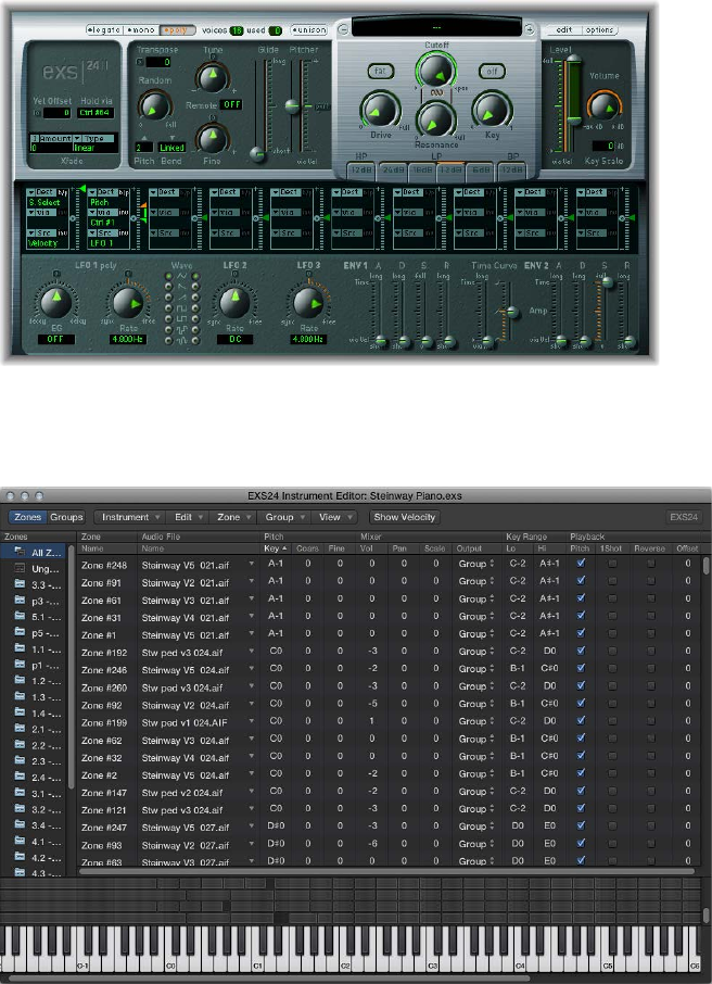
Chapter 9 EXS24 mkII 158
There are two EXS24 mkII windows.
•Parameter window: This window is used to load sampler instruments and contains synthesis
and modulation options that enable you to customize your sounds. See EXS24 mkII Parameter
window overview.
•Instrument Editor window: This window is used to create and edit sampler instruments.
Click the Edit button in the Parameter window to open the Instrument Editor window. See
EXS24 mkII Instrument Editor overview.
Chapter 9 EXS24 mkII 159
Sampler instruments
Sampler instruments overview
A sampler instrument is the le type that is loaded into EXS24 mkII. You load sampler
instruments using the Sampler Instruments pop-up menu directly above the Cuto knob. When
you choose a sampler instrument, the associated audio les are automatically located on the
hard disk (or disks), and are loaded into your computer’s RAM. You play and record the loaded
sampler instrument in the same way as any software instrument.
A sampler instrument tells EXS24 mkII which samples—audio les—to use, and how to organize
them into zones and groups.
•A zone is a location into which a single sample—an audio le—can be loaded from a hard
disk.
•Zones can be assigned to groups, which provide parameters that allow you to simultaneously
edit all zones in the group. You can dene as many groups as required.
EXS24 mkII is compatible with the following audio le formats: AIFF, WAV, SDII, and CAF. Each
audio le is loaded into EXS24 mkII as a separate sample. Each audio le is then automatically
assigned to a zone in the EXS24 mkII Instrument Editor window. These zones can be edited and
organized into sampler instruments. See Zone and group edit overview on page 19 9.
Important: Audio les are not contained within a sampler instrument. The sampler instrument
only stores information about audio lenames, parameter settings, and locations on the hard
disk. If you delete or rename an audio le, any sampler instrument that uses this le will not be
able to nd it. You can move audio les to another location on your system, however, because
EXS24 mkII automatically searches for les when you load a sampler instrument.
EXS24 mkII is compatible with the SoundFont2, DLS, Gigasampler, and ReCycle sample formats,
as well as the Vienna Library. See Import SoundFont2, DLS, and Gigasampler les on page 162
and Convert ReCycle les to sampler instruments on page 165.
Sample storage locations
To be visible in the EXS24 mkII Sampler Instruments pop-up menu, instruments must be stored
in the Sampler Instruments subfolder of any of the following folders:
•~/Library/Application Support/Logic: User-dened or edited instruments are stored here.
•/Library/Application Support/Logic: Factory-supplied sampler instruments are installed here.
•…/ProjectName: MainStage also searches for sampler instruments in the project folder.
Search by project is included for backward compatibility with existing projects.
•If you use the Save As command, old project les and folders are converted to project
bundles. The original les are not changed.
• If you save a new project, sampler instruments and samples are saved with the
project bundle.
Note: You can store your sampler instruments in any folder on any connected hard disk. Create
an alias pointing to this folder within a Sampler Instruments subfolder (using any of the paths
listed above) and they are shown in the Sampler Instruments pop-up menu.
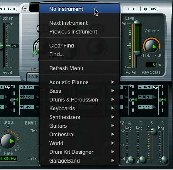
Chapter 9 EXS24 mkII 160
Manage sampler instruments
As your sample library grows, the list of sampler instruments also expands. To help you
keep the list of sampler instruments manageable, EXS24 mkII provides a simple, exible le
management method.
It is recommended that you copy any sampler instruments and all associated audio les to
your hard drive. This provides access to your sampler instruments with no need to nd and
insert CD-ROM or DVD discs, and it also enables you to organize your sampler instruments to
meet your needs. Load times are faster, and you can play back samples that exceed the size of
your computer’s RAM by streaming them from your hard disk. This feature is not practical for
optical drives.
If you are using Logic Pro X, you can save sampler instruments and associated audio les with
the project bundle. This makes it easy to keep all sampler instruments and audio samples in
one place.
Organize your sampler instruments into a preferred hierarchy
1 Create a folder on the desktop—named Basses, for example—and drag it into the target folder.
2 Drag the sampler instruments you want to move into this newly created folder.
The modied menu structure is reected when you open the Sampler Instruments
pop-up menu.
Note: Use the Refresh Menu command in the Sampler Instruments pop-up menu after changes
are made to the folder hierarchy in the Sampler Instruments folder.
The Sampler Instruments pop-up menu displays submenus only for folders that actually contain
sampler instrument les. Other folders are not added to the menu. Aliases pointing to folders
that contain sampler instrument les outside the Sampler Instruments folders can also be added
to the menu. The Sampler Instruments folder itself can be an alias to a folder on a dierent drive
or in another location.
Chapter 9 EXS24 mkII 161
Copy sampler instruments to your hard drive
1 To open the Library folder in a Finder window, Option-click the Go menu from the desktop, then
click Library.
2 Copy the sampler instrument le into the ~/Library/Application Support/Logic/Sampler
Instruments folder.
3 Copy the associated samples into a folder named Samples in the same folder as the Sampler
Instruments folder.
Create a backup of sampler instruments in MainStage
1 To copy the audio and sampler instrument les of all currently active sampler instruments in the
project to a specied le location, choose Consolidate from the File > Project menu.
Tip: You can also do this by saving a project. By default, sampler instruments and samples are
saved in the project bundle. For more information, see MainStage Help.
2 In the dialog, choose the type of les you want to copy or move.
Choose Delete empty folders after moving, if applicable.
3 Click the Copy or Move button.
Use sampler instruments and settings
Sampler instruments are distinct from plug-in settings, which are loaded and saved in the
plug-in window header. Each has advantages and disadvantages for handling parameter values
in the Parameter window.
Typically, you store the current Parameter window settings into the loaded sampler instrument.
This overrides the settings currently saved in the loaded sampler instrument. Alternatively, you
can save a new sampler instrument.
A plug-in setting, by comparison, stores all parameter adjustments made in the Parameter
window, but these settings are distinct from the sampler instrument being loaded. A plug-in
setting contains only a pointer to an associated instrument, which means that loading a setting
also loads the assigned sampler instrument.
This separation between plug-in settings and sampler instruments enables you to use sampler
instruments as you would use waveforms in a synthesizer. For example, you could create a
plug-in setting with guitar-like envelope, modulation, and lter parameter values. You would
then use the Sampler Instruments pop-up menu to load an instrument without any existing
settings, such as a ute, to create a plucked or strummed ute sound.
Important: Using sampler instruments as described requires that they contain no settings.
Remove settings from an existing sampler instrument
1 Choose Options > “Save Instrument as” to create a copy of the sampler instrument (see
EXS24 mkII Options pop-up menu commands on page 170).
2 Choose Options > Delete Settings from Instrument to remove the settings from the
copied instrument.
Note: All of the factory-supplied sampler instruments contain settings, so you need to follow the
steps above to use these instruments in this way.
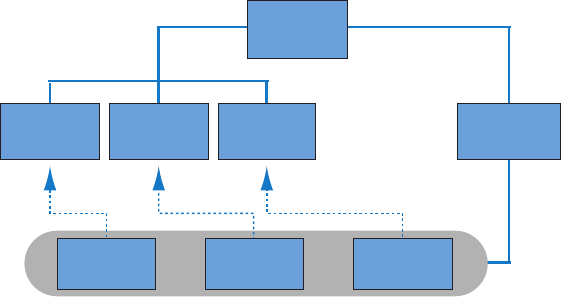
Chapter 9 EXS24 mkII 162
Import SoundFont2, DLS, and Gigasampler les
EXS24 mkII recognizes SoundFont2, DLS, and Gigasampler les placed inside the Sampler
Instruments folder and converts them into sampler instruments.
You can store your imported sampler instruments in any folder on any of your computer’s hard
drives. To access these instruments from the Sampler Instruments pop-up menu, you need to
create an alias pointing to the target folder within the ~/Library/Application Support/Logic/
Sampler Instruments folder.
Import SoundFont2, DLS, or Gigasampler les into EXS24 mkII
1 To open the Library folder in a Finder window, Option-click the Go menu from the desktop, then
click Library.
2 Copy or move your SoundFont2, DLS, or Gigasampler les into the ~/Library/Application
Support/Logic/Sampler Instruments folder.
3 Choose the SoundFont2, DLS, or Gigasampler le from the Sampler Instruments pop-up menu.
EXS24 mkII automatically converts the chosen le into a sampler instrument, as follows:
•A sampler instrument le is created in the Sampler Instruments folder. This contains the le in
its original format.
•The raw samples associated with the sampler instrument are placed in one of the following
folders, depending on the format being converted:
•~/Library/Application Support/Logic/SoundFont Samples
•~/Library/Application Support/Logic/Gigasampler Samples
•~/Library/Application Support/Logic/DLS Samples
Logic
(folder)
Gigasampler
sampler
instrument
DLS
sampler
instrument
SoundFont
sampler
instrument
Sampler
Instruments
Sampler
Instruments
(folder)
SoundFont
Samples
(folder)
Gigasampler
Samples
(folder)
DLS Samples
(folder)
The procedure outlined above also applies when you are importing SoundFont2 les. These le
types contain multiple sounds in addition to single-instrument les.
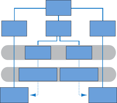
Chapter 9 EXS24 mkII 163
When you load a SoundFont2 Bank into EXS24 mkII, it creates a Bank folder and a Samples folder,
named after the SoundFont2 Bank le. The word Bank or Samples is appended to each folder
name. A sampler instrument le is automatically created for all sounds in the bank, and placed in
the new Bank folder. The Sampler Instruments pop-up menu automatically updates to reect the
new folder hierarchy. All samples associated with the bank are automatically added to a Samples
folder inside the SoundFont folder. For example, if you load a SoundFont2 bank le named
Vintage Drums, which contains over 50 individual drum kits from several dierent vintage drum
machines, into EXS24 mkII, the following happens:
•A new folder named Vintage Drums Bank is created in the ~/Library/Application Support/
Logic/Sampler Instruments folder.
•A second folder named Vintage Drums Samples is created in the ~/Library/Application
Support/Logic/SoundFont Samples folder.
•The Sampler Instruments pop-up menu hierarchy is updated and the original Vintage Drums
entry is replaced with a Vintage Drums.Bank entry. This new entry is a folder that contains the
individual sampler instruments, which can be selected and loaded as usual.
Sampler
Instrument
category
Logic
(folder)
Sampler
instruments
Sampler
Instruments
(folder)
EXS
Samples
(folder)
SoundFont
Samples
(folder)
Basses
(folder)
Vintage
Drums Bank
(folder)
Acoustic Bass
(sampler
instrument)
Vintage Drums Kit 1
(sampler
instrument)
Vintage drums
samples
Acoustic bass
samples
After conversion is complete, the original SoundFont2 or Gigasampler source les can be deleted
from the hard disks.
Chapter 9 EXS24 mkII 164
Convert audio regions to sampler instruments
You can convert audio regions to sampler instruments with the Convert Regions to New Sampler
Track function (default key command: Control-E). All selected regions are sequentially mapped—
in accordance with their timeline positions—to the specied key range, starting with the
lowest note.
A new track is also created, with automatically created trigger notes for the converted audio
regions. These trigger notes match the time positions of the source audio regions. You can
reposition or edit the trigger notes in the Piano Roll editor. You can also change zone parameters
in the EXS24 mkII Instrument Editor. See EXS24 mkII Instrument Editor overview.
Convert audio regions to sampler instruments and tracks
1 In the Tracks window, select the audio regions you want to convert.
2 Right-click or Control-click any selected region, then choose Convert > Convert Regions to New
Sampler Track (or use the default key command: Control-E).
3 In the dialog, choose to Create Zones From either Regions or Transient Markers.
4 Enter the EXS Instrument Name in the eld.
5 Set the Trigger Note Range in one of the following ways:
•Play a low key on your MIDI keyboard to set the low note of the trigger range. Play a second
key to set the top note of the trigger range.
•Choose a low and high note from the Trigger Note Range pop-up menus.
6 Click OK to create a new sampler instrument and track or click Cancel if you change your mind.

Chapter 9 EXS24 mkII 165
Convert ReCycle les to sampler instruments
ReCycle, a sample editing program from Propellerhead Software, can generate a number of le
types that can be read by Logic Pro and EXS24 mkII.
ReCycle separates sample material into small segments called slices, based on waveform peaks,
or transients, in the audio le. In this way, ReCycle is able to split an audio le into musically
relevant slices. The timing of these slices—in a drum loop, for example—is also mapped to an
automatically generated region in Logic Pro.
EXS24 mkII supports the following ReCycle le types:
•Old ReCycle le: These les have the .rcy sux, and the abbreviation for this le type is RCSO.
These les are no longer commonly used.
•Old ReCycle export le: These les have the .rex sux, and the abbreviation for this le type is
REX. A number of older sample libraries include REX format les.
•ReCycle 2.0 le: These les have the .rx2 sux, and the abbreviation for this le type is REX2.
These les are used extensively by Propellerhead Reason, and many popular sample libraries
include REX2 format les.
Create a new sampler instrument and assign each ReCycle slice to a zone
1 Choose Instrument > ReCycle Convert > Extract MIDI Region and Make New Instrument in the
Instrument Editor.
2 Select the ReCycle le, and click Open.
3 Enter a velocity factor in the Create MIDI Region dialog.
The velocity factor analyzes the loudness—transient peak—of each slice in the imported ReCycle
le. It then maps this value to a corresponding velocity value for the MIDI note event that is used
to trigger the slice.
•If you enter a positive value (up to 100), louder slices generate MIDI note events with higher
velocity values.
•If you enter a negative value, louder slices generate MIDI note events with lower
velocity values.
4 Click OK.
EXS24 mkII generates a zone for each slice of the imported ReCycle le and assigns these zones
to a single group. The new sampler instrument is named after the ReCycle loop. If a sampler
instrument of that name already exists, a number sign (#) and a number are appended to the
name. For example, if you import a ReCycle le named Tricky Backbeat but Tricky Backbeat
already exists as a sampler instrument, the imported instrument would be named Tricky
Backbeat#1, thus ensuring that the lename is unique within the Sampler Instruments folder.
In addition, a MIDI region is generated on the currently selected track, at the current project
position, rounded to whole bars. You use this MIDI region to trigger the imported slices at the
timing dened by the ReCycle le. You can generate new MIDI regions at any time from the
imported sampler instrument (see “Generate a new MIDI region from a ReCycle instrument”), so
you can feel free to modify or delete the region.
Chapter 9 EXS24 mkII 166
Tip: The Extract MIDI Region and Add Samples to Current Instrument command also allows you
to add the slices of a ReCycle loop to any sampler instrument currently opened in the Instrument
Editor. This allows you to use several dierent ReCycle loops in a single sampler instrument.
Assign a complete ReCycle loop to a zone
mChoose Instrument > ReCycle Convert > Slice Loop and Make New Instrument to create a
sampler instrument from a ReCycle loop.
Each slice is chromatically mapped across the keyboard—from low to high notes.
Each zone plays back the ReCycle loop to the end point, at the current project tempo. This
means that the lowest zone plays back the entire loop, but the highest zone plays only the last
slice of the loop. Notes between the lowest and highest zones play several slices. This allows for
drum’n’bass-style note triggering, where the sample loop start point is determined by playing
the respective notes on the keyboard.
If you want to add zones from the sliced loop to the currently active sampler instrument, you can
choose Instrument > ReCycle Convert > Slice Loop and Add Samples to Current Instrument.
Paste ReCycle loops from the Clipboard
You can generate a MIDI region from imported ReCycle les. These regions trigger the imported
slices at the timing dened by the ReCycle les.
mChoose Edit > Paste ReCycle Loop as New Instrument to create a sampler instrument from a
ReCycle loop that was copied to the Clipboard using ReCycle’s Copy Loop feature.
Instrument creation is identical to the Extract MIDI Region and Make New Instrument command.
If you want to add zones to the currently active sampler instrument, you can choose Edit > Paste
ReCycle Loop to Current Instrument.
Generate a new MIDI region from a ReCycle instrument
You can generate a MIDI region from imported ReCycle les. These regions trigger the imported
slices at the timing dened by the ReCycle les.
mChoose Instrument > ReCycle Convert > Extract Region(s) from ReCycle Instrument.
MIDI regions are created on the currently selected track, at the current project position, rounded
to bars. A single MIDI region is generated for each imported ReCycle loop in the currently open
instrument. You will also need to enter a velocity factor (see “Create a new sampler instrument
and assign each ReCycle slice to a zone”).

Chapter 9 EXS24 mkII 167
EXS24 mkII Parameter window
EXS24 mkII Parameter window overview
You use the EXS24 mkII Parameter window to change and control the entire loaded sampler
instrument. You control individual samples (zones), or grouped samples, in the Instrument Editor
window. See EXS24 mkII Instrument Editor overview on page 192.
Global parameters
Modulation and
control parameters
Modulation router
Output parameters
Sampler instruments field Filter parameters Pitch parameters
Global parameters
The Parameter window contains the following parameter groups:
•Sampler Instruments pop-up menu and eld: Click to access, nd, and load your sampler
instruments. The name of the loaded sampler instrument is displayed in the eld. The related
Edit and Options buttons are to the right. See Use the Sampler Instruments pop-up menu on
page 168.
•Global parameters: Use to select and congure sampler instruments, dene the polyphony, set
crossfades, and so on. See EXS24 mkII global parameters overview.
•Pitch parameters: Use to adjust tuning, transposition, and pitch bend behavior. See EXS24 mkII
pitch parameters on page 174.
•Filter parameters: Use to shape the tonal color of the loaded sampler instrument. See EXS24
mkII lter overview on page 176.
•Output parameters: Use to control the level and keyboard scaling of the loaded sampler
instrument. See EXS24 mkII output parameters on page 178 .
•Extended parameters: Click the disclosure triangle at the lower left of the interface to access
additional MIDI and randomization parameters. See EXS24 mkII extended parameters.
•Modulation router: Use the modulation router in the strip across the center of the interface to
link modulation sources, such as envelopes and LFOs, to modulation targets, such as oscillators
and lters. See Use the EXS24 mkII modulation router on page 180.
•Modulation and control parameters: Use the modulation and control parameters in the area
immediately below the router to assign and adjust the LFOs and envelopes. See EXS24 mkII
modulation overview on page 179.

Chapter 9 EXS24 mkII 168
Sampler Instruments pop-up menu
Use the Sampler Instruments pop-up menu
This section outlines the use of the Sampler Instruments pop-up menu. The Edit button opens
the Instrument Editor window. The Options button opens a pop-up menu. See EXS24 mkII
Options pop-up menu commands on page 170 .
Load an instrument
1 Click the Sampler Instruments eld to open the Sampler Instruments pop-up menu.
Click here to open the sampler
instruments menu.
2 Choose the sampler instrument you want to edit or play.
Load the next or previous instrument in your sampler instrument library
Do one of the following:
mClick the plus or minus button to choose the next or previous instrument in your sampler
instrument library.
mChoose Next Instrument or Previous Instrument from the Sampler Instruments pop-up menu (or
use the Next EXS Instrument or Previous EXS Instrument key command).
If EXS24 mkII is the key focus window, you can also use the following key commands:
•Next Plug-In Setting or EXS Instrument
•Next Channel Strip or Plug-In Setting or EXS Instrument
•Previous Plug-In Setting or EXS Instrument
•Previous Channel Strip or Plug-In Setting or EXS Instrument
Tip: You can also browse through your sampler instruments by using your MIDI keyboard. The
Sampler Preferences window oers Previous EXS Instrument and Next EXS Instrument options.
These allow you to assign a MIDI event, such as a MIDI note, control change, or program change
to select the previous or next sampler instrument. See EXS24 mkII preferences on page 214.
Update the Sampler Instruments pop-up menu
mChoose Refresh Menu from the Sampler Instruments pop-up menu.
Choosing this menu item scans all default le locations and updates the Sampler Instruments
pop-up menu. Use this command when you have nished importing or creating new
sampler instruments.
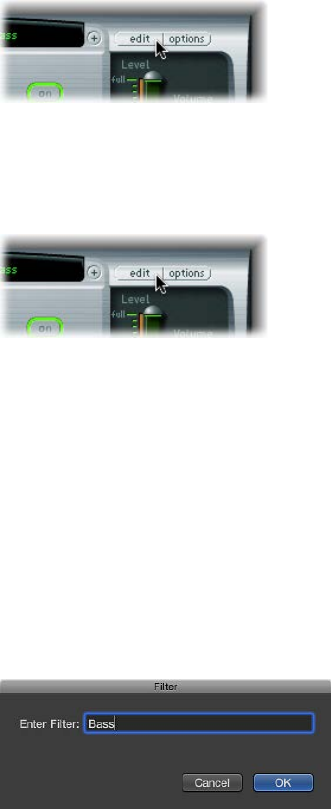
Chapter 9 EXS24 mkII 169
Load sampler instruments from other locations
You can manually load sampler instruments that are not shown in the Sampler Instruments
pop-up menu. This is done using the Instrument pop-up menu in the Instrument Editor window.
1 To open the Instrument Editor window, click the Edit button in the Parameter window.
2 Choose Instrument > Open, then browse to the instrument in the dialog.
Open the Instrument Editor window
mClick the Edit button to open the Instrument Editor window.
Note: Clicking the Edit button when no sampler instrument is loaded also opens the Instrument
Editor window and automatically creates a new, empty, sampler instrument. See EXS24 mkII
Instrument Editor overview on page 192.
Search for sampler instruments
To minimize the number of sampler instruments displayed in the Sampler Instruments pop-up
menu, you can use the Find function. This limits the Sampler Instruments pop-up menu to
displaying only sampler instrument names that contain the search term.
Search for sampler instruments
1 Choose Find from the Sampler Instruments pop-up menu.
2 Enter the search term in the Filter dialog.
Disable the search lter
mChoose Clear Find from the Sampler Instruments pop-up menu.
The full Sampler Instruments pop-up menu is displayed, but the search term you typed in the
Filter dialog is not cleared. You can return to the limited menu by choosing Enable Find from the
Sampler Instruments pop-up menu. This allows you to switch between the two views without
re-typing the search term.
Perform a dierent search
mChoose Find from the Sampler Instruments pop-up menu again, then enter the search term.

Chapter 9 EXS24 mkII 170
EXS24 mkII Options pop-up menu commands
Click Options to open a pop-up menu of settings and sampler instruments management
commands, to import non-native samples and instruments, and to access EXS24 mkII preferences
and memory management.
•Recall Default EXS24 Settings: Recalls a neutral setting for all parameters in the Parameter
window. This provides a “clean slate” when you are adjusting the parameters of your
sampler instrument.
•Recall Settings from Instrument: Recalls the original parameter settings of the loaded sampler
instrument. This option is useful if you’ve been overzealous with your tweaking and want to
return to the original sampler instrument parameter settings.
•Save Settings to Instrument: Stores the current parameter values of the Parameter window in
the sampler instrument le. When the instrument is reloaded, these values are recalled.
•Delete Settings from Instrument: Removes the stored settings (Parameter window values) from
the sampler instrument le.
•Rename Instrument: Allows you to rename the loaded instrument, which overwrites the
existing instrument name.
•Save Instrument as: Allows you to enter an alternative name for the loaded instrument,
which preserves the original name and sampler instrument le, but creates a new sampler
instrument—a copy.
Note: This is a good, safe option to use because any projects or templates that use the
originally named sampler instrument will work as expected.
•Delete Instrument: Deletes the loaded sampler instrument.
•(Recall Default EXS24 mkI Settings): Recalls the parameter settings of sampler instruments
created in the older version of the EXS24—notably, the modulation paths (see EXS24 mkI
modulation paths on page 183). This option is not relevant for sampler instruments created in
EXS24 mkII.
•Extract MIDI Region(s) from ReCycle Instrument: Extracts regions contained in a ReCycle
instrument. If no ReCycle instrument is selected, this option is dimmed. See Convert ReCycle
les to sampler instruments on page 165.
•SoundFont Convert, DLS Convert, Giga Convert: Each of these commands opens a dialog with
instructions about performing the respective conversions. See Import SoundFont2, DLS, and
Gigasampler les on page 162 for details.
•Preferences: Opens EXS24 mkII preferences (see EXS24 mkII preferences on page 214).
•Virtual Memory: Opens a conguration dialog for EXS24 mkII’s virtual memory functions. Virtual
memory allows samples of almost unlimited length to be played back, by streaming audio
directly from the hard disk in real time. The Virtual Memory dialog also enables direct access
to system memory for EXS24 mkII—in systems with 5 GB of RAM or more. See EXS24 mkII
memory management on page 217.
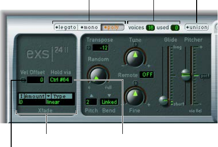
Chapter 9 EXS24 mkII 171
EXS24 mkII global parameters
EXS24 mkII global parameters overview
The global parameters aect the overall behavior of EXS24 mkII.
Hold via fieldCrossfade parameters
Vel Offset field
Unison buttonVoices/Used fieldsKeyboard mode buttons
Global parameters
•Keyboard mode buttons: Switch EXS24 mkII between legato, monophonic, and polyphonic
behaviors. See Set the EXS24 mkII keyboard mode on page 172.
•Unison button: Turns Unison mode on or o. See Use Unison and Voices in EXS24 mkII on
page 172.
•Voices and Used elds: Set the maximum number of notes that can be played simultaneously.
The Used eld is a real-time monitor that indicates the number of voices that are actually used
when you play the keyboard.
•Vel Oset eld: Increases or decreases incoming MIDI note velocity values by ±127, expanding
or limiting the dynamic response to MIDI note events.
•Hold via eld: Sets the modulation source used to trigger the sustain pedal function (hold all
currently played notes, and ignore note-o messages until the modulation source value falls
below 64). The default is MIDI controller number CC 64 (the standard MIDI “Hold/Sustain”
controller number).
•Crossfade parameters: Use to crossfade between layered samples—zones—with adjacent
velocity ranges. See EXS24 mkII crossfade parameters on page 173.

Chapter 9 EXS24 mkII 172
Set the EXS24 mkII keyboard mode
A polyphonic instrument, such as an organ or piano, allows several notes to be played
simultaneously. Brass or reed instruments are monophonic, which means that only one note can
be played at a time. EXS24 mkII lets you choose an appropriate keyboard mode for the type of
instrument that is loaded. You are free to use a monophonic mode for polyphonic instruments,
which allows playing styles that are not possible with polyphonic instruments.
Change the keyboard mode
mClick the Legato, Mono, or Poly button.
•In Legato mode, only one note can be played at a time. The envelope generators are
retriggered only if you play staccato—releasing each key before playing a new key.
•In Mono mode, staccato playing retriggers the envelope generators every time a new note
is played. If you play in a legato style (play a new key while holding another), the envelope
generators are triggered only for the rst note you play legato, then they continue their curve
until you release the last legato played key.
•In Poly mode, several notes can be played simultaneously.
Note: In many classic monophonic analog synthesizers, the behavior in Legato mode is referred
to as single trigger, while Mono mode is referred to as multi trigger.
Use Unison and Voices in EXS24 mkII
In Unison mode, up to 64 voices are played when a key is struck. This enables a richer sound,
achieved by slightly detuning each voice. This is ideal when you are emulating classic
analog synthesizers.
Voices are equally distributed in the panorama eld and are evenly detuned. You can use the
Random knob to determine the amount of tuning deviation between voices.
Note: The number of voices actually used per note increases with the number of layered
sample zones.
Use monophonic unison mode
1 Click the Mono or Legato button, depending on the keyboard mode you want to use. See Set the
EXS24 mkII keyboard mode.
2 Click the Unison button.
•The intensity of the unison eect depends on the number you set in the Voices eld. Increase
the Voices value for a fatter sound.
•The intensity of detuning—voice deviation—depends on the value you set with the Random
knob. See EXS24 mkII pitch parameters on page 174.

Chapter 9 EXS24 mkII 173
Use polyphonic unison mode
mClick the Poly and Unison buttons.
In Poly/Unison mode, each played note is eectively doubled, or—more correctly—the
polyphony value of the Voices parameter is halved. These two voices are heard when you trigger
the note. Selecting Poly and Unison has the same eect as setting the EXS24 mkII to Mono and
Unison with Voices set to 2, but you can play polyphonically.
Set the number of voices
mDrag the Voices eld to determine the maximum number of voices (polyphony) that EXS24 mkII
can play.
The Used eld is a real-time monitor that indicates the number of voices in use when you play
the keyboard. If the Voices and Used elds show the same value most of the time (causing voices
to drop out), set a higher Voices value.
EXS24 mkII crossfade parameters
The crossfade (Xfade) parameters enable you to crossfade between layered samples—known as
zones in EXS24 mkII—with adjacent velocity ranges.
When you assign a sample to a zone, you can set the lowest and highest MIDI note velocity that
will trigger that zone. The area between these values is known as the zone’s velocity range. You
can layer zones—dierent samples—on the same keyboard note, and trigger them individually
by playing at dierent velocities. For example, imagine the following two layered samples, zone 1
and zone 2, on MIDI note A#2:
•Zone 1 is a sample of a snare drum hit lightly and a little o-center. It has a MIDI note velocity
range of 24 to 90.
•Zone 2 is a sample of a snare drum hit hard in the center of the drum head. It has a velocity
range of 91 to 127.
In this example, the maximum velocity range value of zone 1 and the minimum velocity range
value of zone 2 are adjacent. If you play note A#2 at velocities above or below a value of 90,
you will clearly hear each sample being triggered. To make this transition less abrupt, use the
crossfade parameters to smoothly fade between each zone. When you have distinctly dierent
audio samples in adjacent zones, you will nd crossfading very helpful in creating realistic-
sounding sampler instruments.
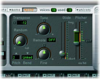
Chapter 9 EXS24 mkII 174
Crossfade (Xfade) parameters
•Amount eld: Expands the velocity range of all zones by applying an identical value to each
layered zone. The crossfade takes place in the extended velocity range area. When the Amount
parameter is set to 0, EXS24 mkII switches from one zone to another.
Note: You can also set other modulation sources, such as the modulation wheel of your MIDI
keyboard, to modulate the Amount parameter. If you do this, the Amount parameter still
functions in the same way, but the crossfade is triggered by the modulation wheel rather than
by velocity.
•Type pop-up menu: Choose the curve type for your velocity crossfade:
•dB lin (dB linear): A logarithmic curve that evenly crossfades between zones
•linear (gain linear): A convex crossfade curve with a rapid volume fade toward the end
•Eq. Pow (equal power): A nonlinear curve with a rapid level increase at the beginning of the
fade. This is useful if your crossfade seems to drop in volume part way through.
EXS24 mkII pitch parameters
The EXS24 mkII pitch parameters enable you to adjust the tuning and transposition of the
loaded sampler instrument.
Pitch parameters
•Tune knob: Rotate to raise or lower the pitch of the sampler instrument in semitone
increments. At the centered position—click the small 0 at the top—no pitch change occurs.
•Transpose eld: Transpose EXS24 mkII in semitone increments. This not only aects the pitch
but also moves the zones by the specied value.
•Random knob: Rotate to set the amount of random detuning applied to each voice. Use this
parameter to simulate the tuning drift of analog synthesizers or to thicken the sound. Random
is also eective when you are emulating various stringed instruments.
•Fine knob: Rotate to tune the sampler instrument in cent increments—1/100th of a semitone.
Use this parameter to correct samples that are slightly out of tune or to create a thick
chorus-like eect.
•Pitch Bend Up and Down pop-up menus: Set the upper and lower limit of pitch bends—in
semitones—that can be introduced by moving your keyboard’s pitch bend wheel. A value of 0
disables pitch bends.
Note: When you choose Linked in the Pitch Bend Down pop-up menu, the bend range is
identical in both directions—for example, if you assign an upward bend of 4 semitones, the
downward bend is also set to 4 semitones, resulting in a combined bend range of 8 semitones
(9, if you include the standard pitch, or “no bend” position).
Chapter 9 EXS24 mkII 175
•Remote eld: Use to remotely change the pitch of complete EXS24 mkII instruments in real
time. You can dene a key on your MIDI keyboard that is used as the original, or “reference”
pitch. After the reference pitch is set, playing any of the keys in a range of ±1 octave above or
below this key changes the pitch of the entire instrument, rather than triggering a sample. This
is similar to the Pitch Bend function but is quantized to semitones.
•Glide and Pitcher sliders: Glide sets the time it takes to slide from one note pitch to another. Its
behavior depends on the Pitcher parameter setting.
•When Pitcher is centered, Glide determines the time it takes for the pitch to slide from one
note to another—the portamento time.
•When Pitcher is set to a position above the center value, Glide determines the time it takes
for the pitch to glide down from this higher value to the normal pitch value.
•When Pitcher is set to a position below the center value, the pitch glides from this lower
setting back up to the normal pitch value.
Pitcher can be modulated by velocity—the upper slider half determines the setting for
maximum velocity, the lower half for minimum velocity. By dragging the area between the
two slider segments, you can move both simultaneously. When the upper half of the Pitcher
slider is set above the center position and the lower half below the center position, lower
velocity values cause the pitch to rise from the lower setting up to the original note pitch,
whereas higher values cause it to fall from the higher setting down to the original note pitch.
When both halves of the Pitcher slider are set either below or above the centered position, a
low or high velocity will slide up or down to the original pitch. Depending on the position of
the upper and lower halves of the slider—relative to the center position—the time required
for the slide up or down to the original note pitch can be adjusted independently for both soft
and hard velocities.
Note: In Legato mode, Glide is active only on tied notes and envelopes are not retriggered
when tied notes are played. In other words, playing a series of tied notes results in only
a single envelope trigger. In Mono mode, Glide is always active and the envelopes are
retriggered by every note played.

Chapter 9 EXS24 mkII 176
EXS24 mkII lter parameters
EXS24 mkII lter overview
These parameters control the EXS24 mkII lter. You can congure the type of lter, lter
resonance, cuto frequency, drive, and amount of key follow. For details about the lter envelope,
see EXS24 mkII envelope overview on page 187.
Filter parameters
•Filter On/O button: Turns the entire lter section and the lter envelope on or o. Disabling
the lter section makes it easier to hear adjustments to other sound parameters because the
lter always heavily aects the sound.
•Filter Mode/Slope buttons: Labeled HP, LP, and BP at the bottom of the lter section, these
buttons determine the type and slope of the lter. See Set the EXS24 mkII lter mode and
slope on page 177.
•Cuto knob: Rotate to set the cuto frequency of the lter. The Cuto value also serves as the
starting point for any modulation involving the lter.
•In a lowpass lter, the higher the cuto frequency is set, the higher the frequencies of signals
that are allowed to pass.
•In a highpass lter, the cuto frequency determines the point where lower frequencies are
suppressed, with only upper frequencies allowed to pass.
•In a bandpass/band-rejection lter, the cuto frequency determines the center frequency for
the bandpass or band-rejection lter.
•Resonance knob: Rotate to boost or cut the frequency area surrounding the cuto frequency.
Very high Resonance values introduce self-oscillation, causing the lter to produce an audible
sine wave.
•In a lowpass lter, resonance emphasizes or suppresses signals below the cuto frequency.
•In a highpass lter, resonance emphasizes or suppresses signals above the cuto frequency.
•In bandpass lters, resonance emphasizes or suppresses the portions of the signal—the
frequency band—that surround the dened frequency, set with the Cuto knob. In EXS24
mkII, Resonance denes the width of the frequency band.
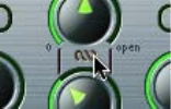
Chapter 9 EXS24 mkII 177
•Drive knob: Rotate to overdrive the lter input, leading to a denser, more saturated signal,
which introduces additional harmonics. Drive aects each voice independently. When every
voice is overdriven individually—like having six fuzz boxes for a guitar, one for each string—
you can play extremely complex harmonies over the entire keyboard range. They’ll sound
clean, without unwanted intermodulation eects spoiling the sound. Some Drive settings
lead to a dierent tonal character. The way analog lters behave when overdriven forms an
essential part of the sonic character of a synthesizer. Each synthesizer is unique in the way its
lters behave when overdriven. EXS24 mkII is exible in this regard, allowing tonal colors that
range from a subtle fuzz to a hard distortion.
•Key knob: Rotate to dene the amount of lter cuto frequency modulation by note number.
When Key is set to the full-left position, the cuto frequency is unaected by the note number
and is identical for all played notes. When Key is set to the full-right position, the cuto
frequency follows the note number one-to-one; if you play one octave higher, the cuto
frequency is also shifted upward by one octave. This parameter is useful for avoiding overly
ltered high notes.
•Fat button: Click to turn on the fatness feature. Fatness preserves the bass frequency response,
even when high Resonance settings are used.
Note: The Fatness parameter applies only to lowpass lters. Fatness is nonfunctional when the
highpass or bandpass lter types are used.
Control two lter parameters at once
mDrag the chain symbol between the Cuto and the Resonance knobs to control both parameters
simultaneously—vertical movements alter Cuto values and horizontal movements aect
Resonance values.
Set the EXS24 mkII lter mode and slope
The EXS24 mkII lter can operate in several modes, allowing specic frequency bands to be
ltered (cut away) or emphasized.
Most lters do not completely suppress the portion of the signal that falls outside the frequency
range dened by the Cuto parameter. The slope, or curve, chosen for the lowpass lter
expresses the amount of rejection below the cuto frequency in decibels per octave. The steeper
the slope, the more severe the eect on signal levels below the cuto frequency.
Select a lter mode and slope
Click one of the following buttons:
mHP (highpass): Allows frequencies above the cuto frequency to pass.
The slope of the highpass lter is xed at 12 dB/octave in HP mode.
mLP (lowpass): Allows frequencies that fall below the cuto frequency to pass. Click any of the four
lter buttons to engage the lowpass lter and to select a lter slope:
•24 dB (4 pole): Use this setting for drastic eects, such as cutting o all but a few notes.
•18 dB (3 pole)
•12 dB (2 pole)
•6 dB (1 pole): Use this setting for creating a slightly warmer sound without drastic lter
eects—to smooth overly bright samples, for example.
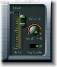
Chapter 9 EXS24 mkII 178
mBP (bandpass): Allows a frequency band directly surrounding the cuto frequency to pass—all
other frequencies are cut.
The Resonance parameter controls the width of the frequency band. The bandpass lter is a two-
pole lter with a slope of 6 dB/octave on each side of the center frequency of the band.
EXS24 mkII output parameters
The EXS24 mkII output parameters dene the level—the perceived volume—of a played note.
The change in level over time is controlled by an envelope generator, ENV 2.
ENV 2 is hard-wired to the dynamic stage of EXS24 mkII—it is always used to control the level of
each note. See EXS24 mkII envelope overview on page 187.
Output parameters
•Level via Vel slider: Determines how velocity aects the volume of the sound. The upper slider
half determines the volume when the keyboard is struck at maximum velocity, and the lower
half determines the volume when the keyboard is struck at minimum velocity. Drag the area
between the two slider segments to move both simultaneously.
•Volume knob: Sets the output level of EXS24 mkII. Adjust to nd the balance between no
distortion and getting the best—the highest—resolution in the channel strip and the Level
via Vel slider.
•Key Scale eld: Modulates the sampler instrument level by note number—position on the
keyboard. Negative values increase the level of lower notes. Positive values increase the level
of higher notes. This is useful when you are emulating a number of acoustic instruments,
where higher-pitched notes are often louder than low notes.
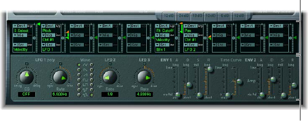
Chapter 9 EXS24 mkII 179
EXS24 mkII extended parameters
EXS24 mkII provides additional parameters that can be accessed by clicking the disclosure
triangle at the lower left of the interface.
Extended parameters
•MIDI Mono Mode pop-up menu: Choose O, On (with common base channel 1), or On (with
common base channel 16).
In either mode, each voice receives on a dierent MIDI channel. Controllers and MIDI messages
sent on the base channel aect all voices.
•Mono Mode Pitch Range pop-up menu: Choose 0, 24, or 48.
The chosen pitch bend range aects individual note pitch bend messages received on
all but the common base channel. The default is 48 semitones, which is compatible with
Mobile GarageBand's keyboard in pitch mode. When using a MIDI guitar, 24 semitones is the
preferable setting because most guitar to MIDI converters use this range by default.
EXS24 mkII modulation overview
EXS24 mkII is equipped with an extensive range of modulation sources and targets, making it
an instrument that can generate extraordinary sounds that constantly evolve, or are just plain
expressive to play.
Modulation and control
parameters
Modulation router
•Modulation router: Links modulation sources, such as the envelope, to modulation destinations,
such as the lter. The router features ten modulation routings—arranged into columns. See
Use the EXS24 mkII modulation router on page 180.
•Modulation and control parameters: Include the LFOs and envelopes. See EXS24 mkII LFO
overview on page 184 and EXS24 mkII envelope overview on page 187.
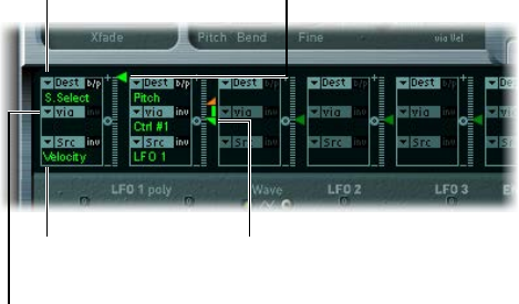
Chapter 9 EXS24 mkII 180
EXS24 mkII modulation router
Use the EXS24 mkII modulation router
The modulation router spans the center of the EXS24 mkII interface. If you are new to synthesizer
modulation routings, see Modulation overview on page 488.
The modulation intensity
slider divides into two
halves when a via
source is active.
Modulation sources are
shown at the bottom of
each modulation routing.
Via sources are shown
in the middle of each
modulation routing.
The modulation intensity
slider is not divided
when there is no active
via source.
Modulation destinations
are shown at the top of
each modulation routing.
Any modulation source can be connected to any modulation destination, or target—much like
an old-fashioned telephone exchange or a studio patch bay.
The modulation intensity—how strongly the destination is inuenced by the source—is set with
the vertical slider to the right of the modulation routing.
The intensity of the modulation can itself be modulated: The via parameter denes a further
modulation source, which is used to control the modulation intensity. When via is active, you can
specify upper and lower limits for the modulation intensity. See Use EXS24 mkII via sources.
Ten such modulation routings of source, via, and target can take place simultaneously, in
addition to routings that are hard-wired outside of the router. It doesn’t matter which of the ten
modulation routings you use.
You can even select the same destination in several parallel modulation routings. You can also
use the same sources and the same via controllers in multiple modulation routings.
The following instructions apply to all ten modulation routings.
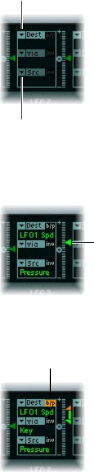
Chapter 9 EXS24 mkII 181
Create a basic modulation routing
1 Choose the parameter you want to modulate from the Dest pop-up menu.
Click here to choose a
modulation source.
Click here to choose a
modulation destination.
2 Choose the parameter you want to use to modulate the destination from the Src pop-up menu.
3 Drag the intensity slider to set a xed modulation intensity.
Modulation intensity
slider
Bypass a modulation routing
mClick the Bypass (b/p) button at the top right of the modulation routing.
Bypass button
The Bypass button disables individual modulation routings without losing settings.
Use EXS24 mkII via sources
In a basic modulation routing consisting of a target and source, you can set a xed modulation
intensity by vertically dragging the arrowhead of the intensity slider to the right of the routing.
The slider value always denes a constant modulation intensity.
The intensity of the modulation can itself be modulated: via denes a further modulation source,
which is used to control the modulation intensity.
If you choose a value other than o (shown as “---”) from the via pop-up menu, the intensity
slider divides into two halves, each half with its own arrowhead.
•The lower half of the slider denes the minimum modulation intensity, when the via
controller—the modulation wheel, for example—is set to its minimum value.
•The upper half of the slider denes the maximum modulation intensity when the via
controller is set to its maximum value.
•The area between the two slider halves denes the modulation range of the via controller.
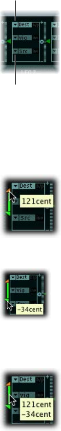
Chapter 9 EXS24 mkII 182
Create a modulation routing that includes a via source
1 Choose the target parameter you want to modulate from the Dest pop-up menu.
Click here to choose a
modulation source.
Click here to choose a
modulation destination.
2 Choose a modulation source from the Src pop-up menu.
3 Choose the modulation source that you want to use for control of modulation intensity from the
via pop-up menu.
4 Vertically drag the upper intensity slider to set the maximum modulation intensity.
5 Vertically drag the lower intensity slider to set the minimum modulation intensity.
Move the entire via range
mVertically drag the area between the two intensity slider halves (the range).
Both arrowheads move simultaneously.
Tip: If this area is too small to drag, just drag an unused section of the intensity slider to move
the area.

Chapter 9 EXS24 mkII 183
Set the modulation intensity to zero
mClick the small 0 symbol that is halfway up the intensity slider control.
Invert the eect of the via modulation source
mClick the Invert (inv) button to invert the eect of the via modulation source.
EXS24 mkI modulation paths
Many of the hard-wired modulation paths that were available as sliders on the original EXS24
(mkI) are now integrated into the modulation router, which was not available in the original
EXS24. To reconstitute the modulation slider conguration of the mkI version, choose Recall
Default EXS24 mkI Settings from the Options pop-up menu. This loads the mkI modulation paths
into the modulation router, as follows:
•Velocity to Sample Select
•LFO 1 to Pitch via ModWheel (= Ctrl#1)
•Velocity to Sample Start (inv)
•LFO 2 to Filter Cuto via ModWheel
•Velocity to Filter Cuto
•Envelope 1 to Filter Cuto via Velocity
•LFO 2 to Pan via ModWheel
You can alter the settings of these modulation paths—allowing you to use modulation sources
that were unavailable in EXS24 mkI.
Note: For technical reasons, the settings of the modulation router cannot be used in EXS24 mkI.
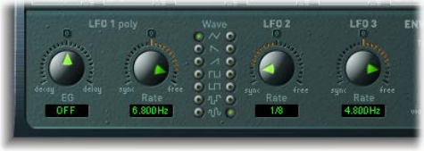
Chapter 9 EXS24 mkII 184
EXS24 mkII LFOs
EXS24 mkII LFO overview
EXS24 mkII includes three LFOs (low frequency oscillators). They are all available as sources and
targets in the router. If you are new to synthesizers and the concept behind LFOs, see Common
modulation sources on page 490.
LFO 1 is polyphonic, which means that if it is used for any modulation of multiple voices, they
will not be phase-locked. LFO 1 is also key-synced—each time you play a key, LFO 1 modulation
of this voice is started from 0.
To understand the non-phase-locked characteristic more fully, imagine a scenario where a chord
is played on the keyboard. If LFO 1 is used to modulate pitch, for example, the pitch of one voice
might rise, the pitch of another voice might fall, and the pitch of a third voice might reach its
minimum value. As you can see, the modulation is independent for each voice, or note.
The key sync feature ensures that the LFO waveform cycle always starts from 0, which results in
consistent modulation of each voice. If the LFO waveform cycles were not synchronized in this
way, individual note modulations would be uneven.
LFO 1 can also be faded in or out automatically, courtesy of a built-in envelope generator.
LFO 2 is monophonic, which means that the modulation is identical for all voices. For example,
imagine that a chord is played on the keyboard. If LFO 2 is used to modulate pitch, the pitch of
all voices in the played chord rises and falls synchronously.
LFO 3 is also monophonic, always using a triangular waveform.
All three LFOs can either oscillate freely or be synchronized to the host application tempo in
values ranging between 32 bars and 1/128 triplets.
LFO parameters
•LFO 1 EG knob: Rotate to set the time it takes for LFO 1 modulation to fade in or fade out (see
Use EXS24 mkII’s LFO 1 envelope generator on page 186).
•LFO 1 Rate knob: Rotate to set the frequency—the speed—of LFO 1 modulation. The value is
displayed in Hertz (Hz) or note values beneath the slider. See Set EXS24 mkII’s LFO rate.
•Wave buttons: Choose the waveform for LFO 1 (left column) and LFO 2 (right column). For
details about how to use them, see EXS24 mkII LFO waveforms on page 185.
•LFO 2 Rate knob: Rotate to set the frequency—the speed—of LFO 2 modulation.
•LFO 3 Rate knob: Rotate to set the frequency—the speed—of LFO 3 modulation.

Chapter 9 EXS24 mkII 185
EXS24 mkII LFO waveforms
You can use the Wave buttons to choose dierent waveforms for LFO 1 and LFO 2. The table
outlines how these waveforms can aect your sounds.
Tip: Try dierent waveforms while a modulation routing of Pitch is engaged and running.
Waveform Comments
Triangle Well-suited for vibrato eects
Sawtooth Well-suited for helicopter and space gun sounds.
Intense modulations of pitch with a negative (inverse)
sawtooth wave lead to “bubbling” sounds. Intense
sawtooth modulations of lowpass lter cuto and
resonance create rhythmic eects. The waveform can
also be inverted, resulting in a dierent start point for
the modulation cycle.
Rectangle Use of the rectangular waves periodically switches the
LFO between two values. The upper rectangular wave
switches between a positive value and 0. The lower
wave switches between a positive and a negative
value set to the same amount above or below 0. You
can achieve an interesting eect by modulating the
Pitch destination with a suitable modulation intensity
that leads to an interval of a fth. Choose the upper
rectangular wave to do so.
Sample & Hold The two lower waveform settings of the LFOs
output random values. A random value is selected
at regular intervals, as dened by the LFO rate. The
upper waveform steps between randomized values
(rapid switches between values). At its lower setting,
the random wave is smoothed out, resulting in uid
changes to values. The term Sample & Hold (S & H)
refers to the procedure of taking samples from a
noise signal at regular intervals. The values of these
samples are then held until the next sample is taken.
Tip: A random modulation of Pitch leads to an eect
commonly referred to as a random pitch pattern
generator or sample and hold. Try using very high
notes, at very high rates and high intensities—you’ll
recognize this well-known eect from hundreds of
science ction movies.
Chapter 9 EXS24 mkII 186
Use EXS24 mkII’s LFO 1 envelope generator
LFO 1 provides a simple envelope generator (EG) that sets the time it takes for the LFO
modulation to fade in or fade out. At its center position (click the middle mark) the modulation
intensity is static—no fade-in or fade-out occurs.
Set the LFO 1 modulation fade time
mTo fade in the modulation: Drag the LFO 1 EG knob to a positive value.
The higher the value, the longer the delay time.
mTo fade out the modulation: Drag the LFO 1 EG knob to a negative value.
The lower the value, the shorter the fade-out time.
Set up a delayed vibrato
LFO envelopes are most often used for delayed vibrato; many instrumentalists and singers
intonate longer notes this way.
1 Drag the LFO 1 EG knob to a position toward the right (Delay), and modulate the Pitch
destination using the LFO1 source in the router.
2 Set a slight modulation intensity.
3 Select an LFO 1 Rate of about 5 Hz.
4 Click the triangular Wave button as the LFO 1 waveform.
Tip: Chaotic and fast modulations of frequencies (choose Pitch from the Destination pop-up
menu) by the LFO 1 source—with a delayed Sample & Hold waveform, a high Rate, and short
fade-out—are ideal for emulating the attack phase of brass instruments.
Set EXS24 mkII’s LFO rate
LFO 2 is ideally suited for creating rhythmic modulation eects—eects that retain perfect
synchronicity even during project tempo changes. LFO 3 is much the same but uses a xed
triangle waveform, making it most suitable for adding vibrato to a sound, or for use as a
modulation source for the other LFOs.
The Rate parameter of all three LFOs allows the respective LFO to run freely (in the right side of
the Rate knob range), or to be synchronized with the project tempo (in the left side of the Rate
knob range).
Set a free LFO rate
mTo run the LFO freely, choose a value in the right side of the LFO Rate knob range.
The rate is displayed in hertz.
Synchronize the LFO rate to the host application tempo
mTo synchronize the LFO with the host application tempo, choose a value in the left side of the
LFO Rate knob range.
The rate is displayed in rhythmic values (when project tempo synchronization is active).
Synchronized rates range from speeds of 1/64-notes to a periodic duration of 32 bars. Triplet and
punctuated values are also available.
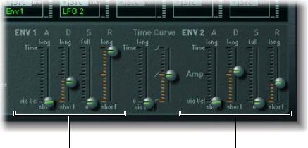
Chapter 9 EXS24 mkII 187
EXS24 mkII envelope overview
EXS24 mkII features two envelope generators per voice, abbreviated as ENV 1 and ENV 2 in
the interface and router. For details on the roots of the term envelope generator and its basic
function, see Amplier envelope overview on page 486.
The parameters of ENV 1 and ENV 2 are identical.
•ENV 1 controls the lter over time.
•ENV 2 denes the changes in level over time—for each note played.
Both envelopes, however, are also available for simultaneous use as sources in the router.
The envelope time parameters (Attack, Decay, and Release) are also available as modulation
destinations in the router.
Envelope 2 parametersEnvelope 1 parameters
Envelope parameters
•A(ttack) slider: Denes the time it takes for the level of a note to rise from an amplitude of 0 to
the set amplitude. The Attack time sliders of both envelopes are divided into two halves.
•The lower slider half denes the attack time when the keys are struck hard, at maximum
velocity. The upper slider half denes the attack time at minimum velocity. Drag the area
between the two slider halves to move them both simultaneously. If this area is too small to
drag, drag above or below the slider in the control area.
•D(ecay) slider: Denes the time it takes for the level of a held note to fall to the sustain level
after the attack phase has completed.
•If the Sustain level parameter is set to its maximum value, the Decay parameter has no eect.
•If the Sustain level is set to its minimum value, the Decay parameter denes the duration or
fade-out time of the note.
•S(ustain) slider: Determines the sustain level.
•R(elease) slider: Denes the time required for the (sustain) level to decay to 0—after the key
is released.
•Time via Key slider: Applies to both envelopes. Scales (lengthens or shortens) the envelope time
intervals. Note that position C3 is the center point.
•Time intervals for zones assigned to keys above C3 can be made shorter with the left slider.
Time intervals for zones assigned to keys below C3 can be made longer.
• Curve slider: The attack curve slider applies to both envelopes, determining the shape of the
envelope attack curve.

Chapter 9 EXS24 mkII 188
EXS24 mkII modulation reference
EXS24 mkII modulation target reference
The following targets, or destinations, are available in the Dest pop-up menu for
real-time modulation.
Destination Comments
Sample Select Modulates the sample (zone) that is played.
By default, Sample Select is controlled by velocity—
through the default Velocity to Sample Select
modulation routing. This means that the received
note velocity value determines which of the layered
zones (in dierent velocity ranges) is heard as you
play the keyboard softer or harder.
You aren’t limited to using velocity, however, to
determine which sample is played. You could assign
the modulation wheel source to the Sample Select
destination, or use both velocity and the modulation
wheel.
If you choose a continuous controller such as
the modulation wheel, you can step through the
velocity layers during playback. If you do this, use
the crossfade (Xfade) parameters to create smooth
transitions between velocity split points.
When you use multiple modulation sources, be
aware that these can cause all velocity layers to run
simultaneously—using up as many voices as there are
layered zones. The CPU usage increases accordingly.
Sample Start Modulates the sample start time. This allows you to
trigger a drum loop partway through, for example.
Glide Time Modulates the duration of the Glide (portamento)
eect. If you modulate Glide, with Velocity selected as
the source, the speed of the keystrike determines the
time it takes for the played notes to reach the target
pitch.
Pitch Modulates the frequency (pitch) of the loaded
sampler instrument. If you select an LFO as the source,
this destination leads to siren or vibrato sounds.
Select one of the envelope generators with 0 attack,
short decay, 0 sustain, and short release as the source
for tom and kick drum sounds. Slight envelope
modulations can make the amount of detuning
change over time, which can be particularly useful for
brass sounds.
Filter Drive Modulates the lter Drive parameter.
Filter Cuto Modulates the Cuto Frequency parameter. See EXS24
mkII lter overview on page 176 .
Filter Resonance Modulates the Resonance parameter of the lter.
Volume Controls the main output level of EXS24 mkII.

Chapter 9 EXS24 mkII 189
Destination Comments
Pan Modulates the panorama position of the sound in the
stereo spectrum. Modulating Pan with an LFO results
in a stereo tremolo (auto panning). In unison mode,
the panorama positions of all voices are spread across
the entire stereo spectrum. Nevertheless, you can still
modulate pan, moving the positions in parallel.
Relative Volume Adds or subtracts the specied amount to or from the
Volume parameter.
LFO 1 Dcy./Dly (Decay/Delay) Controls the LFO 1 EG parameter (see Use
EXS24 mkII’s LFO 1 envelope generator on page 186).
LFO 1 Speed Modulates the frequency (rate) of LFO 1. You can
automatically accelerate or slow down LFO 1’s rate by
modulating the LFO 1 Speed destination with one of
the envelope generators (ENV) or with LFO 2 or LFO 3.
LFO 2 Speed As above, for LFO 2
LFO 3 Speed As above, for LFO 3
Env 1 Attack Modulates the Attack time of the lter envelope.
Env 1 Decay Modulates the Decay time of the lter envelope.
Env 1 Release Modulates the Release time of the lter envelope.
Time Modulates the Time via Key slider position—see Time
Curve sliders description in EXS24 mkII envelope
overview on page 187.
Env 2 Attack (Amp) Modulates the Attack time of the second envelope
generator.
Env 2 Decay (Amp) Modulates the Decay time of the second envelope
generator. If you select Env 2 Decay as the destination
and Velocity as the source, the duration of the
decaying note depends on how hard you strike the
key. Selecting Key(board) as the source results in
higher notes decaying more quickly (or slowly).
Env 2 Release (Amp) Modulates the Release time of the second envelope
generator.
Hold Modulates the (alternate) controller assigned to
the sustain pedal function. See the Hold parameter
information in EXS24 mkII global parameters
overview on page 171.

Chapter 9 EXS24 mkII 190
EXS24 mkII modulation source reference
The following modulation sources are available in the Src pop-up menu:
Source Comments
Side Chain Side Chain modulation uses a side-chain signal as
a modulation signal. The side-chain source can be
chosen from the Side Chain pop-up menu in the
header of the plug-in window. It is fed to the internal
envelope follower, which creates a modulation value
based on the current side-chain input signal level.
Maximum Max sets the value of this source to +1 (an internal
value that indicates the maximum possible amount
for this source). This oers interesting options for
controlling the modulation intensity with all possible
via values.
ENV 1 Envelope Generator 1 is used as a source.
ENV 2 (Amp) Envelope Generator 2 is used as a source. Env 2 always
controls the level of the overall sound.
LFO 1 LFO 1 is used as a source.
LFO 2 LFO 2 is used as a source.
LFO 3 LFO 3 is used as a source.
Release Velocity The modulation occurs when you release a key
(this requires a keyboard that sends release velocity
information).
Pressure Pressure (also known as aftertouch) serves as a
modulation source. EXS24 mkII reacts to poly pressure
(polyphonic aftertouch).
Note: If you set the destination to Cuto, the cuto
frequencies rise and fall, depending on how rmly you
press a key on your touch-sensitive MIDI keyboard—
after the initial keystrike.
Pitch Bend The pitch bend wheel is used as a modulation source.
Key Kybd (Keyboard) outputs the keyboard position (the
MIDI note number). The center point is C3 (an output
value of 0, used internally by EXS24 mkII). An output
value of −1 indicates ve octaves below the center
point. An output value of +1 indicates ve octaves
above. Modulate the Cuto destination with the Key
source to control the cuto frequencies of the lter
with the keyboard position—as you play up and
down the keyboard, the cuto frequencies change.
A modulation intensity of 0.5 proportionately scales
cuto frequencies with keyboard note pitches.
Velocity Velocity serves as a modulation source.
--- Disables the source.
MIDI Controllers 1–120 The MIDI controller you choose serves as a
modulation source.
Controllers 7 and 10 are marked Not available. Logic
Pro uses these controllers for volume and pan
automation of channel strips. Controller 11 is marked
Expression. It has a xed connection to this function,
but it can also be used to control other modulation
sources.

Chapter 9 EXS24 mkII 191
EXS24 mkII modulation via source reference
The following sources may be chosen from the Via pop-up menu to control the modulation
intensity.
Via source Comments
Side Chain Side Chain modulation uses a side-chain signal
as a modulation intensity (trigger) signal. You can
choose the side-chain source from the Side Chain
pop-up menu in the upper-right corner of the plug-in
window. It is fed to the internal envelope follower,
which creates a modulation value based on the
current side-chain input signal level.
Maximum Sets the value of this source to +1.
ENV 1 Envelope Generator 1 controls the modulation
intensity.
ENV 2 (Amp) Envelope Generator 2 controls the modulation
intensity.
LFO 1 The modulation uses the speed and waveform of
LFO 1, which controls the modulation intensity.
LFO 2 The modulation uses the speed and waveform of
LFO 2, which controls the modulation intensity.
LFO 3 The modulation uses the speed and waveform of
LFO 3, which controls the modulation intensity.
Release Velocity The modulation will be more or less intense
depending on how quickly you release the key.
Note: This requires a keyboard that sends release
velocity information.
Pressure If you choose Pressure (also known as aftertouch) from
the Via pop-up menu, the modulation intensity will
be touch sensitive—modulation will be more or less
intense depending on how rmly you press the key
of your touch-sensitive MIDI keyboard after the initial
keystrike.
Pitch Bend The pitch bend wheel controls the modulation
intensity.
Key Key(board) outputs the keyboard position—the MIDI
note number. The center point is C3, an output value
of 0. Five octaves below and above, an output value
of −1 or +1, respectively, is sent. If you select Pitch as
the destination, modulate it with the LFO1 source,
and select Key as the via value, the vibrato depth
changes, depending on key position. In other words,
the vibrato depth will be dierent for notes higher or
lower than the dened Key(board) position.
Velocity The modulation intensity will be velocity sensitive;
modulation will be more or less intense depending on
how quickly—that is, how hard—you strike the key.
--- Disables the via source.
MIDI Controllers 1–120 Modulation intensity is determined by the MIDI
controller value you choose.
Controllers 7 and 10 are marked Not available. Logic
Pro uses these controllers for volume and pan
automation of channel strips. Controller 11 is marked
Expression. It has a xed connection to this function,
but it can also be used to control other modulation
sources.

Chapter 9 EXS24 mkII 192
EXS24 mkII Instrument Editor window
EXS24 mkII Instrument Editor overview
The Instrument Editor is used to create and edit sampler instruments. A sampler instrument
consists of zones and groups:
•A zone is a location into which a single sample (an audio le) is loaded from a hard disk. You
can edit zone parameters in Zones view.
•Zones can be assigned to groups, which provide parameters that allow you to simultaneously
edit all zones in the group. You can dene as many groups as required. You can edit group
parameters in Groups view.
Note: The Instrument Editor is available only when Advanced Editing is enabled in your host
application preferences.
See Create EXS24 mkII instruments on page 195, Create EXS24 mkII zones, Create EXS24 mkII
groups, and Zone and group edit overview on page 199.
The Instrument Editor window has two views: Zones view and Groups view. Zones view displays
zones and associated parameters in the parameter area. Groups view shows groups and
associated parameters. See EXS24 mkII Zones and Groups view.
Important: Due to the level of integration between EXS24 mkII and Logic Pro, several sections
cover features that are not available in MainStage.
Open the EXS24 mkII Instrument Editor
mClick the Edit button in the Parameter window.
Note: If no sampler instrument is loaded when you click the Edit button, a new instrument is
automatically created.
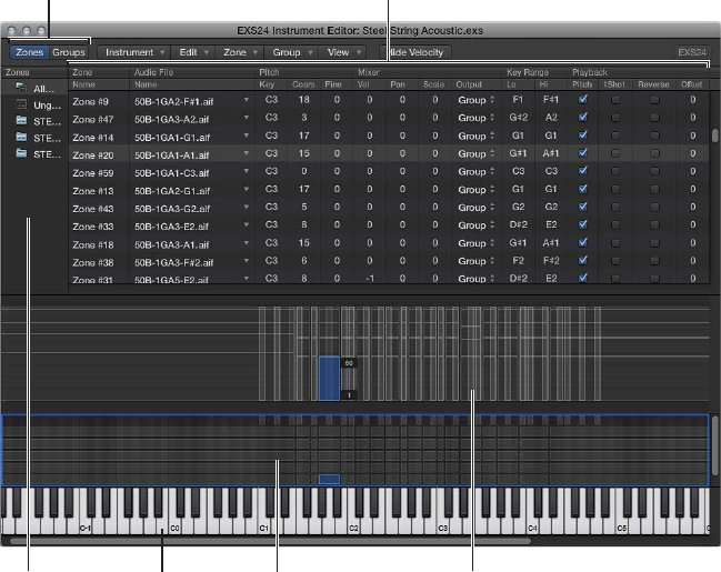
Chapter 9 EXS24 mkII 193
EXS24 mkII Zones and Groups view
There are two views in the Instrument Editor window: Zones and Groups.
In Zones view, the area above the keyboard displays the Zones area. The general menus, buttons,
and so on, are displayed in both Zones and Groups views.
Velocity areaZones/Group areaKeyboardZones column
Parameters area
Click to switch between
Zones and Groups views.
•Zones column: Displays all zones of the instrument. By default, every instrument contains All
Zones (which includes “grouped” zones) and Ungrouped. Click either All Zones or Ungrouped
to display the associated zones in the Parameters area.
•Parameters area: Displays the parameters of the zone (individual, all, or ungrouped) chosen in
the Zones column.
•Velocity area: Shows the velocity range of the selected zone.
Note: The Velocity area is turned o, by default.
•Zones/Groups area: Visually indicates the zones or groups above the keyboard.
•Keyboard: Click notes to trigger the associated zone. The keyboard also serves as a visual
reference for the placement of zones or groups (in the Zones/Groups area).
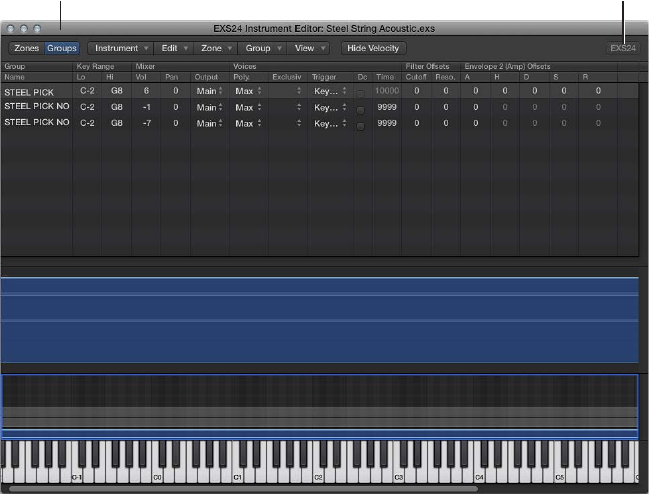
Chapter 9 EXS24 mkII 194
In Groups view, the area above the keyboard displays Groups. The general menus, buttons, and
so on, are displayed in both Zones and Groups views.
Instrument Editor in
Groups view
Click here to reopen a closed
EXS24 mkII Parameter window.
Note: Clicking the EXS24 button does not display the Parameter window in the foreground if it is
covered by other oating windows.
Switch between EXS24 mkII Instrument Editor views
mClick the Groups button in the upper-left corner to switch to Groups view, or click the Zones
button in the upper-left corner to switch to Zones view. You can also use the Toggle Zones/
Groups View key command to switch between views.

Chapter 9 EXS24 mkII 195
Create instruments, zones, and groups
Create EXS24 mkII instruments
You can add zones and groups to loaded instruments, or you can create a new, empty
instrument and ll it with zones and groups.
Important: EXS24 mkII cannot directly record samples as you would with a hardware sampler.
You need to record the samples in a suitable application, such as Logic Pro.
Create a new instrument
mIf you are in the Parameter window and no sampler instrument is loaded: Click the Edit button.
mIf you are in the Instrument Editor window: Choose Instrument > New.
For information about loading sampler instruments, see Use the Sampler Instruments pop-up
menu on page 168. For information about saving, renaming and exporting sampler instruments,
see Save, rename, and export EXS24 mkII instruments on page 211.
For information about creating zones and groups, see Create EXS24 mkII zones on page 195 and
Create EXS24 mkII groups on page 198.
Create EXS24 mkII zones
A zone is a location into which a single sample—or audio le, if you prefer this term—can be
loaded. The sample loaded into the zone is memory resident—it uses the RAM of your computer.
A zone oers parameters that control sample playback. Each zone enables you to determine the
Key Range—the range of notes that the sample spans—and the Root Key—the note at which
the sample sounds at its original pitch. In addition, Sample Start, End, and Loop points, Volume,
and several other parameters can be adjusted for the zone. You can dene as many zones as
needed.
Create a zone, and assign a sample to it
1 Choose Zone > New Zone (or use the New Zone key command).
A new zone entry appears in the Instrument Editor.
2 Do one of the following:
•Double-click the empty area in the Audio File column.
•Click the arrow in the Audio File column, then choose Load Audio Sample from the
pop-up menu.

Chapter 9 EXS24 mkII 196
3 Locate the audio le you want and select it.
•If you select the “Hide used audio les” checkbox, les used in the currently loaded sampler
instrument are dimmed.
•If you select the “Preview audio le in EXS Instrument” checkbox, the sample les in the
currently selected zone are temporarily replaced. The zone is not directly triggered by
selecting this option, but it can be triggered by playing MIDI notes while the le selector is
open—and dierent les are chosen. The selected sample can be heard as part of the zone,
inclusive of all synthesizer processing (lters, modulation, and so on).
4 To loop playback of the currently selected sample le, click the Play button.
•Click the Play button a second time to stop playback.
•Click the Play button, then step through the les using the Down Arrow key, or by clicking
them, to audition each le in turn.
5 When you nd a sample you want to use, click the Open button to add it to the zone.
When the sample is loaded, the sample’s name is displayed in the Audio File Name eld.
Create a zone by dragging an audio le to a key
mDrag an audio le onto one of the keys of the onscreen keyboard.
The start key, end key, and root key are all set to the note that the le was dragged to. Drag-
and-drop works for audio les from the following sources: Browser, Project Audio Browser, and
the Finder.
Create a zone by dragging an audio le to a range of keys
mDrag an audio le directly into the zone area to create a new zone.
The root key for the zone is the key at which the sample is played at its recorded pitch. This
information is written in the sample header. If no root key is dened in the sample header, the
C3 key is used by default.
Note: If you drag an audio le onto an existing zone, the le referenced by that zone is replaced
with the new, dropped le. The pointer changes to reect the replace mode.
Dragging a single sample into the empty area below Ungrouped Zones creates a default zone
and a default group, with the new default zone placed in the default group.

Chapter 9 EXS24 mkII 197
Create multiple zones in one operation
1 Choose Zone > Load Multiple Samples in the Instrument Editor (or use the Load Multiple
Samples key command).
2 Browse to the source les location, then use the Add or Add All buttons to select the samples
you want to use.
3 Click Done.
4 Choose one of the three automatic mapping modes in the dialog that appears:
•“Auto map” by reading the root key from audio le: Uses the root keys stored in the audio le
headers, and places the samples, as zones, across the keyboard range. The number of keys that
constitute a zone is intelligently determined by the placement of neighboring zones.
•“Drums” zone without range, root key from audio le: Uses the root keys stored in the audio le
headers. Each zone is mapped to a single key on the keyboard—as determined by the root
key information.
•Contiguous zones: Ignores all root key information and maps the samples across the keyboard
in chromatic order. The Zone Width eld allows you to specify the width—the key range—of
the newly generated zones. The Start Note eld denes the start note of newly generated
zones.
You can also load multiple samples by dragging them into the Instrument Editor. Dragging
multiple samples into a group folder assigns the samples to the respective group. Dragging
multiple samples below the Ungrouped Zones area assigns the audio les to a new
default group.
Note: If you drag multiple les onto one of the keyboard keys, the dialog does not include the
Start Note eld, because the start key, end key, and root key are all set to the note that the le
was dropped on.
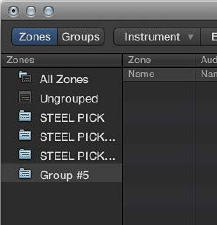
Chapter 9 EXS24 mkII 198
Create EXS24 mkII groups
Imagine a drum kit with a number of dierent samples used in several zones, mapped across
the keyboard. You might decide that you want to change the parameters of each sample
independently—to alter the decay of the snare, or to use a dierent cuto setting for the hi-hat
samples, for example.
In this context, EXS24 mkII’s groups feature is useful. Groups allow for exible sample
organization. You can dene as many groups as you need and assign each zone to one of these
groups. In a drum kit, for example, you could assign all kick drums to Group 1, all snares to Group
2, all hi-hats to Group 3, and so on.
A group makes it possible to dene a velocity range for all assigned zones, allowing you to
specify a velocity window in which the grouped zones will be triggered, for example. Each
group also features oset parameters for the amplitude envelope and lter settings made in the
Parameter window.
You can also play all zones without dening and assigning any groups—in this case, changes to
parameter settings aect all samples (in all zones) equally.
Create a new group
mChoose Group > New Group in the Instrument Editor.
A new group appears in the Zones column at the left side of the Instrument Editor.
Assign a zone to a group
Do one of the following:
mSelect the group in the zone’s Group pop-up menu.
mSelect a zone in the Instrument Editor, Finder, or Project Browser—then drag it into a group
displayed in the Zones column.
mDrag an ungrouped zone (or multiple selected zones) into the empty area below the Ungrouped
Zones icon. This creates a new group, containing the dragged zone, or zones.
mDrag a zone (or multiple selected zones) from one group to any of the following:
•Another group, if you want to change the previous group assignment to the new group.
•The Ungrouped Zones icon, if you want to change the previous group assignment to
unassigned—ungrouped.
•The empty area below the Ungrouped Zones icon, if you want to create a new group
containing the dragged zone, or zones.
Tip: If you press Option while dragging zones to another group, you will copy—rather than
move—the selected zones.
Chapter 9 EXS24 mkII 199
Delete all groups that do not have a zone assignment
mChoose Group > Delete Unused Groups in the Instrument Editor.
Remap pitch bend and modulation wheel events
To create realistic-sounding performances in an easy and intuitive way, the Jam Pack 4
(Symphony Orchestra) instruments use the modulation wheel to switch between articulations—
legato, staccato, and so on. The pitch bend wheel is used to change expression—crescendo,
diminuendo, and so on. For more information, see the Jam Pack 4 documentation.
This is achieved by internally remapping pitch bend events to MIDI controller 11 and modulation
wheel events to MIDI controller 4. To ensure compatibility with the Jam Pack 4 instruments,
EXS24 mkII automatically uses this remapping behavior for Jam Pack 4 instruments.
Remap pitch bend and modulation wheel events in EXS24 mkII
mTo use this remapping model for other instruments, choose Map Mod & Pitch Wheel to Ctrl 4 &
11 from the Instrument menu.
EXS24 mkII remaps incoming pitch bend and mod wheel events to controller 11 or controller 4,
respectively.
Note: The default pitch bend and modulation wheel functions cannot be used in this mode.
Edit EXS24 mkII zones and groups
Zone and group edit overview
Zones and groups oer unique parameters that enable you to customize your sampler
instrument.
You can use the zone parameters to edit the pitch, velocity range, panorama, looping parameters,
and other aspects of zones.
You can use the group parameters to adjust the velocity and output and to oset envelopes and
lters for a group of zones, for example.
Editing techniques, menu selection commands, and other parameter interactions that are shared
by zones and groups are discussed in these sections:
•Zone and group Edit menu commands on page 205
•Select a zone or group for editing on page 200
•Show or hide zone and group parameters on page 204
•Graphically edit EXS24 mkII zones and groups on page 205
For information about parameters that dier between zones and groups, see EXS24 mkII zone
parameters on page 207 and EXS24 mkII group parameters on page 210.
Note: Click the EXS24 button in the top-right corner of the Instrument Editor window to reopen
a closed Parameter window and bring it to the foreground. This button is dimmed when the
Parameter window is open.
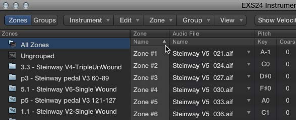
Chapter 9 EXS24 mkII 200
Select a zone or group for editing
There are a number of ways you can select zones and groups for editing.
To make selection easier, you can rst use the sort options.
Sort zones or groups
You can easily sort zones and groups in the Instrument Editor. For example, if you want to sort
your zones by name, click the Name subcolumn heading in the Zone column and your zones
are sorted alphabetically. If you want to sort groups by lowest to highest starting velocity, click
the Low subcolumn heading in the Velocity Range column. The group with the lowest starting
velocity range is displayed at the top of the list.
Do one of the following:
mClick the subcolumn heading that you want to sort by.
mClick the triangle to invert, or reverse, the sort order.
Select zones or groups using Edit menu commands
mChoose one of the following zone and group selection commands from the Edit menu:
•Select All: Selects all zones and groups of the loaded sampler instrument.
•Toggle Selection: Switches the selection between the currently selected zones or groups and all
currently unselected zones or groups.
Select zones or groups by clicking them or pressing arrow keys
mClick zones and groups in the Parameters area to select them.
•To select a single zone or group: Click the parameters of that zone or group.
•To select two nonadjacent zones and the zones between them: Shift-click the two
nonadjacent zones.
•To select multiple nonadjacent zones: Command-click each zone.
mPress the Up Arrow key or the Down Arrow key to select the previous or next zone or group.
Switch EXS24 mkII zones using a MIDI keyboard
mChoose Select Zone of Last Played Key from the Zone menu to switch between zones by
pressing a key on a connected MIDI keyboard. You can continue to select zones by clicking them
in the Instrument Editor when this feature is enabled.
Switch EXS24 mkII groups using a MIDI keyboard
mChoose Select Group of Last Played Key from the Group menu to switch between groups by
pressing a key on a connected MIDI keyboard. This is useful when you want to adjust the velocity
of an instrument’s groups, for example.

Chapter 9 EXS24 mkII 201
Make advanced EXS24 mkII group selections
You can dene a specic event to use as a group selection switch. Whenever the dened
selection event is triggered, zones pointing to this group can be played, while other groups
selected with a dierent event are not played. The dened event does not play or alter a sound; it
acts only as a group selection switch.
The Select Group By command is available in the View menu when you are in Groups view.
Group selection lters
The following group selection lters are available in the Type column pop-up menu:
•Note: Used to select a group by MIDI note. You need to assign multiple groups to a dierent
MIDI note; if the note is triggered, playback of the other group is stopped.
•Group: Used to select a group based on membership of a master group. You need to assign
multiple groups to one master group; if any group member within the master group is
triggered, playback of the other group or groups is stopped.
•Control: Used to select a group based on a specied controller number.
•Bend: Used to select a group by bend range. Groups are played only if they fall within the
specied bend range.
•MIDI Channel: Used to select a group by MIDI channel. Groups are played only if they match
the channel.
•Articulation ID: Used to select a group based on the articulation ID. This parameter is available
as a modulation destination, so you can switch between sample groups with a controller. For
example, you could use your keyboard modulation wheel to switch between several hi-hat
groups with dierent opening degrees.
•Tempo: Used to select a group by tempo. Groups are played only if they fall within the
specied tempo range.
Chapter 9 EXS24 mkII 202
Dene a “base” group and switch between groups with MIDI notes
If you want EXS24 mkII to automatically switch between two string sample groups, for
example—one for staccato samples and one for legato samples—you could set the Select Group
By menu to MIDI notes, and assign a dierent MIDI note to trigger each group. You can then use
a note that is not triggering a sound as a remote group switch.
The following assumes that several groups already exist. See Create EXS24 mkII groups.
1 Click the Groups view button, then choose the Select Group By command from the View menu.
The Select Group By elds are displayed in the Group view.
2 Choose Note in the pop-up menu shown in the Type column for the rst group you want
to switch.
This is the base group. The default note number is C-2, shown in the No. column eld.
3 Drag vertically in the No. column eld to change the note number of the base group.
This should be a note that has no assigned zone. When you play this note, this group is
selected—all other groups are unselected.
4 Choose Note from the pop-up menu shown in the Type column for the second group you want
to switch.
5 Drag vertically in the No. column eld to change the note number of the second group.
This should be a note that has no assigned zone. When you play this note, the second group is
selected—all other groups are unselected.
Rene group selection conditions
You can use multiple group selection criteria to rene your group selections. For example,
you could specify that only a particular range of specied controller message values switches
between dierent articulations, for example. This could be further rened with a second Select
Group By selection with MIDI channel specied as the group selection criteria.
Do one of the following:
mClick the plus sign in the upper-right corner of the Select Group By column.
Select Group By (2) elds are displayed in the Group view.
mClick the minus sign to remove a Select Group By condition and to broaden the group
selection criteria.
Chapter 9 EXS24 mkII 203
Set up a round robin in EXS24 mkII
The term round robin is used to describe sample switching when a single key is struck repeatedly.
This feature can be particularly useful in live performance or for avoiding abrupt, machine-gun-
like eects when switching between real instrument samples.
In EXS24 mkII, you can use a group as the selection criteria for the Select Group By condition.
When one group is played, other groups are silent.
1 Click the Sampler Instruments pop-up menu and load an instrument.
2 Click the Edit button to open the Instrument Editor window. Click the Zones button if Groups
view is shown.
3 Assign two zones to the same key (note C2, for example) and play the onscreen keyboard or play
C2 on a connected MIDI keyboard.
You can see and hear two samples (zones) being played. For clarity, these are zone 1 and zone 2.
4 Now assign another zone to another note (C3, for example) on the onscreen keyboard.
Play C3 on a connected MIDI keyboard and you will hear a dierent zone being triggered. This is
zone 3.
5 Drag vertically in the Lo column for zone 3 until C2 is shown.
6 If you repeatedly strike C2, you will hear zones 1, 2, and 3 being played.
Repeat steps 4 and 5 for other notes, if required.
7 Click the Groups button to switch to Groups view.
8 Choose Group: Group Select By from the View menu.
9 Click the Type subcolumn on the row of zone 2, then choose Group from the pop-up menu.
10 Click the Group subcolumn on the zone 2 row and choose zone 1.
11 Repeat steps 9 and 10 on the zone 3 row, but choose zone 2 in the Group column.
12 Repeatedly click note C2 on the onscreen keyboard or play C2 on a connected MIDI keyboard.
You can hear zones 1, 2, and 3 switched one after the other.
This example illustrates the use of groups as the selection or switching criteria. The selection of
zone 1, zone 2, and zone 3 in the Group menu enables you specify the trigger group for another
group. Because these trigger groups are unique in the Group column, you will sequentially step
through groups.

Chapter 9 EXS24 mkII 204
Show or hide zone and group parameters
Use the View menu to determine which zone and group parameters are shown in the Instrument
Editor:
•View All: Shows all available columns and subcolumns.
•Individual Zone and Group display settings: Choose the individual columns and subcolumns you
want to display. The zone entries are available in Zones view. The group entries are available in
Groups view.
Tip: Press Option, then choose a disabled zone or group column to limit the display to the
chosen column.
•Restore to Default: Reverts to the default view.
•Save as Default: Saves the current view of zone and group parameters as the default view
whenever you open the Instrument Editor.
Use zone and group output labels
You can name the outputs used by instrument zones or groups and can save these names as a
label set.
Set output labels for zones and groups
1 To open the Output Labels window, choose Instrument > Output Labels.
2 Click the eld in the Label column to the right of the Output that you want to rename and type
the new name.
Press Enter or click outside the eld to complete text entry.
3 Select the new name from the Output subcolumn for the zone or group.
Save a label set
1 Choose Save Label Set As from the pop-up menu in the Output Labels window.
2 Type a name in the Label Set Name eld, then click Save.
The label set name is shown in the pop-up menu in the Output Labels window.
Load a label set
mChoose the label set name from the pop-up menu in the Output Labels window.
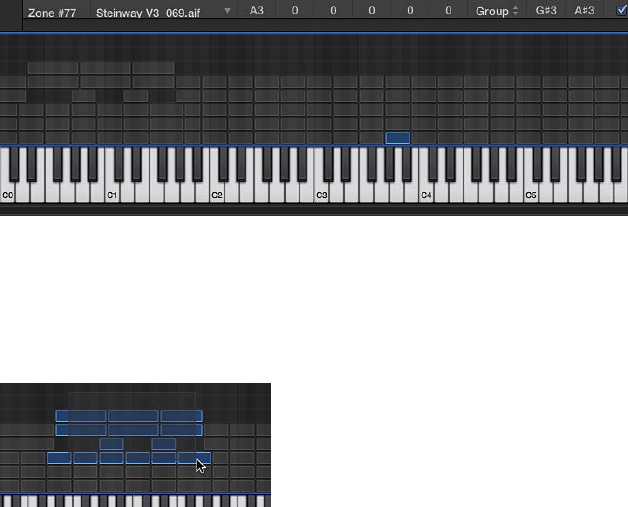
Chapter 9 EXS24 mkII 205
Reset a label set
mChoose Reset Label Set As from the pop-up menu in the Output Labels window.
All changes that you have made to label names are reset.
Delete a label set
1 Choose the label set name from the pop-up menu in the Output Labels window.
2 Choose Delete “label set name” from the pop-up menu in the Output Labels window.
Zone and group Edit menu commands
Use the Edit menu for all basic sampler instrument editing operations, such as copying zones,
undoing edit operations, and so on.
•Undo: Allows the most recent change to the sampler instrument to be undone.
•Redo: Undoes the last Undo command.
•Cut, Copy, Paste: The standard commands for cutting, copying, and pasting values. You can also
cut, copy, and paste selected zones and groups.
•When you copy groups in Zones view, the selected groups and their associated zones are
copied. The group assignments of the zones are retained.
•When you copy groups in Groups view, only the groups themselves are copied, not the
associated zones.
•Delete: Deletes the currently selected zone or group.
Graphically edit EXS24 mkII zones and groups
You are not limited to editing zones and groups in the Parameters area. You can also graphically
edit a number of zone and group parameters in the Zones/Groups Display area above the
keyboard. If you want to edit the audio le of a zone, see Edit samples in the Logic Pro Audio File
Editor on page 212 .
Move a zone or group
mDrag the zone or group to the target position.
Move multiple zones or groups
mShift-click or drag to select the zones or groups, and drag them to the target position.
Change the root key when moving a zone
mHold down Command-Option while dragging the zone.
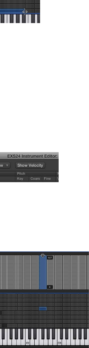
Chapter 9 EXS24 mkII 206
Change the start or end note of a zone or group
1 Move the pointer to the beginning or end of a zone or group (the pointer changes to the resize
icon).
2 Drag the start or end point of the zone or group to the target position.
Move a zone to the left or right
mUse one of the following key commands:
•Shift Selected Zone(s)/Group(s) Left: Option–Left Arrow key
•Shift Selected Zone(s)/Group(s) Right: Option–Right Arrow key
Shift both the root note and the zone position
mUse one of the following key commands:
•Shift Selected Zone(s)/Group(s) Left (Zones incl. Root Key): Shift–Option–Left Arrow key
•Shift Selected Zone(s)/Group(s) Right (Zones incl. Root Key: Shift–Option–Right Arrow key
Edit the velocity range of a zone or group
1 Click the Show Velocity button at the top of the Instrument Editor (or use the Show/Hide Velocity
key command).
The Velocity Display area opens above the Zones/Views Display area.
2 Click one or more zones or groups in the Velocity Display area.
The velocity bars of the selected zones/groups are highlighted in the Velocity Display area.
3 Move the pointer to either the High or Low value of the velocity bar that you want to change
(the pointer changes to the resize icon).
4 Drag upward to raise the value, or downward to lower the value.
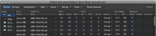
Chapter 9 EXS24 mkII 207
EXS24 mkII zone parameters
The zone parameters provide extensive control over each zone, or sample, in your
sampler instrument.
Zone parameters
•Zone Name eld: Displays the zone name. New zones are automatically assigned a consecutive
number. Click a zone number to enter a name.
•Audio File menu: Displays the audio lename. Move the pointer over a name to reveal a help
tag with additional information, such as format, bit depth, sample rate, and so on. To display
the full le path in the help tag, press Command before the help tag appears. Click the arrow
to open a shortcut menu that contains the following commands:
•Load Audio Sample: Opens a dialog where you can select an audio le. Default key
command: Control-F.
•Open in Audio File Editor: Opens the selected sample in the Logic Pro Audio File Editor (or
the sample editor chosen in the Open External Sample Editor preference). Default key
command: Control-W.
Note: This command is available only when Destructive audio editing is enabled in your host
application preferences.
•Reveal in Finder: Shows the full path of the loaded audio le in the Finder.
Tip: Double-click the name of a sample in the Audio File > Name column to open the
audio le in the Logic Pro Audio File Editor. When no audio le is loaded, the audio le
selector opens.
•Pitch elds: Key determines the root note of the sample—in other words, the note at which
the sample will sound at its original pitch. Use the Coarse and Fine elds to tune the sample in
semitone/cent increments.
•Volume eld: Adjusts the overall output level of the zone.
•Pan eld: Adjusts the pan position of the zone. This parameter works only when EXS24 mkII is
used in stereo.
•Scale eld: Balances the level of a sample across the selected key range. A negative value
makes lower notes softer than higher notes; positive values have the opposite eect.
•Output menu: Determines the outputs used by the zone. Choices include the main outputs,
and paired channels 3 and 4, 5 and 6, 7 and 8, 9 and 10, or individual outputs 11 through 16.
This allows individual zones to be routed independently to aux channel strips (in a multi-
output EXS24 mkII instance).
•Key Range elds: The two key range parameters allow you to dene a key range for the zone.
Playing notes outside this range does not trigger the sample assigned to this zone.
•Lo: Sets the lowest note for the zone.
•Hi: Sets the highest note for the zone.
•Pitch checkbox: Click to change the sample pitch when triggered by dierent keys. When
disabled, the sample is always played at its original pitch, regardless of the note played.
Chapter 9 EXS24 mkII 208
•1Shot checkbox: Click to make the zone ignore the length of incoming MIDI note events—
resulting in the sample always being played from beginning to end whenever a note-on event
is received. This is useful for drum samples, where you often don’t want the MIDI note length
to aect sample playback. Also see the Fade eld parameter below.
•Reverse checkbox: Click to play the sample from the end to the beginning.
•Group menu: Shows the group assignment of a zone. For more information, see Create
EXS24 mkII groups on page 198 and EXS24 mkII group parameters on page 210.
•Velocity Range checkbox and elds: Click the checkbox, then dene a velocity range for the
zone. Playing notes outside this velocity range does not trigger the sample assigned to
this zone.
•Lo: Sets the lowest velocity that will trigger the zone.
•Hi: Sets the highest velocity that will trigger the zone.
•Sample Start and End elds: Set the sample start and end points, respectively. Control-click
either eld to open a shortcut menu that allows you to open the sample in the Logic Pro
Audio File Editor (or an external editor), where you can set the start and end points graphically.
See Edit samples in the Logic Pro Audio File Editor on page 212 , or Use an external instrument
editor with EXS24 mkII.
•Fade eld: Determines the fade-out time for a one-shot sample. The value is shown in samples.
The dierence between the value specied in this eld and the value shown in the End eld
determines the fade-out duration. The lower the value, the longer it takes for the sample to
reach a 0 level (at the sample end point). This option is dimmed when the Loop On checkbox
is active. See EXS24 mkII zone loop parameters on page 209.
Note: This parameter defaults to a value of 0, except when the Sampler Instrument is created
with Logic Pro’s Audio > Convert Regions to New Sampler Track command. This feature uses
transient markers and results in a default Fade eld value that matches the slicing oset of the
following transient marker.
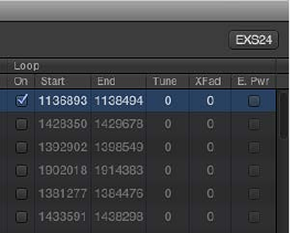
Chapter 9 EXS24 mkII 209
EXS24 mkII zone loop parameters
EXS24 mkII can loop playback of either an entire sample or a portion of it, when sustained MIDI
notes are received.
Zone loop parameters
•Loop On checkbox: Click to enable looping and to allow access to the other Loop parameters.
•Loop Start, Loop End elds: Dene discrete loop start and end points, allowing you to loop a
portion of the audio le.
Control-click either eld to open a shortcut menu that allows access to the Logic Pro Audio
File Editor (or an external editor). This enables you to set the loop start and end points
graphically: Loop Start is represented by the LS marker and Loop End by the LE marker. See
Edit samples in the Logic Pro Audio File Editor on page 212 .
•Tune eld: Changes the tuning of the looped portion of the audio le in cent increments.
•Xfade (Crossfade) eld: Determines the crossfade time between the end/start of a looped
sample. In a crossfaded loop, there is no “step” between the loop end and loop start points. The
higher the value, the longer the crossfade and the smoother the transition between the loop
end and start points. This is especially convenient with samples that are hard to loop and that
would normally produce clicks at the transition point—the join in the loop.
•E. Pwr (Equal Power) checkbox: Click to enable an exponential crossfade curve that causes a
volume boost of 3 dB in the middle of the crossfade range. This fades out/fades in the join
between the loop end and start points at an equal volume level.
Note: The ideal settings for the Xfade and E. Pwr parameters depend on the sample material.
A loop that cycles reasonably smoothly is the best starting point for a perfectly crossfaded
loop, but a crossfaded loop does not always sound better. Experiment with both parameters to
learn how, when, and where they work best.
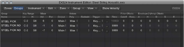
Chapter 9 EXS24 mkII 210
EXS24 mkII group parameters
Group parameters provide simultaneous control of all assigned zones.
Group parameters
•Group Name eld: Displays the group name. Click to enter a name.
•Key Range elds: Dene a key range for the group.
•Lo: Sets the lowest note for the group.
•Hi: Sets the highest note for the group. Playing notes outside this range does not trigger the
zones assigned to this group.
Note: Take your time with these parameters because as they override zone range settings,
possibly making some zones inaudible.
•Vol(ume): Adjusts the overall level of the group—and, therefore, the volume of all zones in the
group. This works much like a subgroup on a mixing console.
•Pan: Adjusts the pan position of the group—stereo balance for stereo samples—and the pan
position of all assigned zones simultaneously.
Note: This will aect any individual zone panning adjustments.
•Output: Determines the outputs used by the group. Choices include the main outputs and
paired channels 3 and 4, 5 and 6, 7 and 8, 9 and 10, or individual outputs 11 through 16.
This allows individual groups to be routed independently to aux channels in a multi-output
EXS24 mkII instance.
Note: This will have an impact on any individual zone output assignments.
•Poly. (polyphony): Determines the number of voices that the group can play. The Max
option ensures that the group uses all voices allowed by the Voices parameter in the
Parameter window.
A practical use of the Poly parameter is to set up a classic “hi-hat mode” within a full drum kit
that is mapped across the keyboard. For example, you could assign an open and closed hi-hat
sample to a group, and set the Voices parameter of the group to 1. The most recently triggered
of the two hi-hat samples mutes the other because only one voice is allowed for the group.
This mirrors the real-world behavior of hi-hats. The other sounds of the drum kit can still be
played polyphonically, if samples in zones are assigned to another group.
•Trigger menu: Determines if zones pointing to this group are triggered on key down (Key
Down setting) or on key release (Key Release setting). This is useful for emulating organ key
clicks, for example, where you may want the organ note triggered on key down, but the organ
click triggered on key release.
•Dc (decay) checkbox: Select the checkbox to access the Decay Time parameter.
•(Decay) Time eld: Determines the time it takes for the level of a sample (triggered by key
release) to decay.
Note: The Decay parameters function only when the Trigger parameter is set to Key Release.
Chapter 9 EXS24 mkII 211
•Cuto and Reso(nance) elds: Independently oset the Cuto and Resonance settings for each
group. This can be useful if you want the initial impact of a note to be unltered for one group
but not other groups.
•Envelope 1/Envelope 2 Osets elds: Independently oset the envelope settings in the
Parameter window for each group. This is useful if you want the lter (Envelope 1) or volume
(Envelope 2) envelopes to aect the samples in a group—after the initial impact of the
triggered sounds.
•H(old) eld: Determines the time that the envelope is held at the maximum attack level, before
the decay phase begins.
Note: When the Trigger parameter is set to Key Release, the Decay Time parameter controls
the decay level, rather than Envelope 2 (the volume envelope). This means that when Trigger is
set to Key Release, the Envelope 2 Osets have no eect.
•Vel(ocity) Range: Sets a velocity range for the group. Velocity Range is useful for sounds where
you want to dynamically mix—or switch between—samples by playing your MIDI keyboard
harder or softer. This feature is ideal for layered sounds, such as a piano/string layer, or when
switching between dierent percussion samples.
•Lo: Sets the lowest velocity that triggers the group.
•Hi: Sets the highest velocity that triggers the group. Playing notes outside this velocity range
will not trigger the zones assigned to this group.
Note: The settings made here override zone settings. When a zone’s velocity range is larger
than the group setting, the zone’s velocity range is limited by the group setting.
Save, rename, and export EXS24 mkII instruments
You can access all basic sampler instrument le operations using the commands in the
Instrument Editor’s Instrument menu.
•Save: Saves the currently loaded sampler instrument. When you create a new instrument
and save it for the rst time, you are asked to provide a name. If you have edited an existing
sampler instrument and use this command, the existing lename is used and the original
instrument is overwritten. You can also use the Save Instrument key command.
•Save As: Saves the currently loaded sampler instrument, but you are prompted to provide a
dierent lename. Use this command when you want to save a copy or multiple versions of an
edited sampler instrument, rather than overwriting the original version.
•Rename: Renames the loaded sampler instrument. The renamed version replaces the original
version on the hard disk.
•Export Sampler Instrument and Sample Files: Copies the selected sampler instrument, including
all associated audio les, to another folder location. Choosing this command opens a dialog
where you can browse to an existing folder or create a new folder. You can also use the Export
Sampler Instrument and Sample Files key command (default: Control-C).
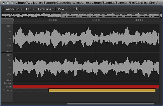
Chapter 9 EXS24 mkII 212
Edit samples in the Logic Pro Audio File Editor
EXS24 mkII and the Logic Pro Audio File Editor are built to work together. The Logic Pro Audio
File Editor provides an intuitive way to adjust sample and loop start and end points by working
directly on a visual representation of the waveform.
Open the Logic Pro Audio File Editor
mControl-click either the Loop Start or Loop End parameter elds of the zone you want to edit in
the Instrument Editor window.
This opens a shortcut menu, which you can use to open the selected sample in the Logic Pro
Audio File Editor (or the external sample editor set in the preferences—see Use an external
instrument editor with EXS24 mkII on page 213.
Edit sample borders and loop points
1 After the sample is opened in the Audio File Editor, drag the sample borders and Loop points
graphically. Loop Start is represented by the LS marker and Loop End by the LE marker.
To accelerate your workow, you can also use the Audio File Editor loop commands:
•Sample Loop → Selection: The loop area—dened by the loop start and end points—is used to
select a portion of the overall audio le.
•Selection → Sample Loop: The selected area is used to set the loop start and end points.
2 Choose Edit > Write Sample Loop to Audio File.
The new loop values are written to the audio le header.
3 Save the sample after you complete your edits.
The new values written to the audio le header are used by EXS24 mkII.
Note: Edited samples may have values that are not accurately shown in the Instrument Editor.
Chapter 9 EXS24 mkII 213
Update zone information
After you save and reopen a sample that was edited in either the Logic Pro Audio File Editor or a
sample editor not made by Apple, it is likely that either the Start and End, or Loop point values—
shown in the Parameters area—will no longer be accurate.
mChoose the Update Selected Zone(s) Info from Audio File command from the Zone menu.
This command reads loop settings and start and end points directly from the audio le and
updates the settings of the zone—shown in the Parameters area—accordingly.
Use an external instrument editor with EXS24 mkII
EXS24 mkII allows you to use external applications to edit your sampler instruments.
Open sampler instruments in an external instrument editor
1 Choose Options > Open in external Instrument Editor in the EXS24 mkII Parameter window.
2 Locate and select the instrument editor software.
3 Repeat step 1, but choose the Open in [name of external instrument editor] command. This is
the same command as above, but it is automatically renamed after an external instrument editor
is assigned.
4 Edit the instrument in the external instrument editor, then use the external instrument editor to
send the instrument back to Logic Pro.
Important: You need to save the edited instrument in Logic Pro—not the external editor—to
make any instrument changes permanent.
Reassign the external instrument editor
mHold down Option while choosing Options > Open in [name of external instrument editor].
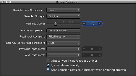
Chapter 9 EXS24 mkII 214
EXS24 mkII preferences
The EXS24 mkII Sampler Preferences window provides access to sample-related preferences, such
as sample rate conversion quality, velocity response, sample storage, search-related parameters,
and so on.
Sampler preferences
•Sample Rate Conversion pop-up menu: Determines the interpolation quality used by EXS24 mkII.
Choose Best to maintain the highest possible sound quality when transposing.
•Sample Storage pop-up menu: Determines the sample format handling method used by
EXS24 mkII.
•Original: Loads samples into RAM at their original bit depth. These are converted to the
internal 32-bit oating point format of the host application on playback.
•32 Bit Float: Samples are stored and loaded in this format. This eliminates the need for real-
time format conversions, meaning that EXS24 mkII handles samples more eciently and can
play back more voices simultaneously.
Note: This requires twice as much RAM for 16-bit samples and a third more RAM for
24-bit samples.
•Velocity Curve slider: Determines how EXS24 mkII responds to incoming velocity values.
Negative values increase the responsiveness to soft key strikes, and positive values
decrease responsiveness.
•Search samples on pop-up menu: Determines the locations that EXS24 mkII will search for
instrument samples. You can choose from:
•Local Volumes: Storage media (hard disks and optical mechanisms) attached to or installed in
the computer.
•External Volumes: Storage media accessible over a network.
•All Volumes: Both internal and network media are scanned for appropriate data.
Note: Choosing External Volumes or All Volumes may result in a dramatic increase in the time
required by EXS24 mkII to nd and load sampler instruments and les.
Chapter 9 EXS24 mkII 215
•Read root key from pop-up menu: Sets the method used by EXS24 mkII to determine the root
key or velocity (or both) of loaded audio les. You can choose from the following:
•File/lename: Initially reads information about the root key/velocity from the audio le itself
(in the header of the AIFF or WAV le) when loading it into a zone. If no information of this
type exists in the le header, a smart analysis of the lename may detect a root key/velocity.
If this second method doesn’t provide useful results, C3 is used as the default root key in
the zone.
•Filename/le: As above, but the lename is read before the header.
•Filename only: Reads from the lename only. If no root key/velocity information exists, C3 is
automatically assigned to the zone as the root key.
•File only: Reads from the le header only. If no root key/velocity information exists, C3 is
automatically assigned to the zone as the root key.
•File/Filename/Analysis: Initially reads information about root key/velocity from the audio
le itself (in the header of the AIFF or WAV le). If no information of this type exists in the
le header, a smart analysis of the lename may detect a root key/velocity. If this method
doesn’t provide useful results, the initial transient in the le itself is analyzed for velocity and
is applied as the velocity. The root key is derived from the initial pitch. C3 is automatically
assigned to the zone as the root key if no pitch is detected.
•Filename/File/Analysis: As above, but the lename is read before the header.
•Analysis only: Analyzes the le only and applies a velocity based on the initial transient level.
The root key is derived from the initial pitch. C3 is automatically assigned to the zone as the
root key if no pitch is detected.
•Root Key at File Name Position pop-up menu: Normally, EXS24 mkII intelligently determines the
root key from the le header of the loaded audio le. On occasion you may want manual
control over this parameter, if you feel that the root key is not being properly determined.
•Auto: Provides a smart analysis of numbers and keys from the lename. A number in the
lename can be recognized, regardless of its format—60 or 060 are both valid. Other valid
numbers can range between 21 and 127. Numerical values outside of these are generally just
version numbers. A key number is also a valid possibility for this use—C3, C 3, C_3, A-1, A-1
or #C3, C#3, for example. The possible range is C-2 up to G8.
•Numeric value: There may be cases where a sound designer has used multiple numbers
in a lename, which is common with loops, with one value being used to indicate
tempo—“loop60-100.wav,” for example. In this situation, it isn’t clear which, if either, of the
numbers indicates a root key or something else: 60 or 100 could indicate the le number
in a collection, tempo, root key, and so on. You can set a value of 8 to read the root key at
position (letter/character) eight of the lename—namely, the 100 (E6). Alternatively, setting a
value of 5 selects the 60 (C3) as the root key position.
Chapter 9 EXS24 mkII 216
•Velocity at File Name Position pop-up menu: EXS24 mkII can determine the velocity from the
le header of the loaded audio le. On occasion you may want manual control over this
parameter, if you feel that the velocity is not being properly determined.
•Auto: Provides a smart analysis of velocity from the lename. An abbreviation in the lename
can be recognized—pp or , for example.
•Numeric value: There may be cases where a sound designer has used multiple letters and
numbers in a lename, which is common with loops, with one value being used to indicate
tempo—“loop-pp.wav,” for example. In this situation, it isn’t clear which, if either, of the /
pp values indicates a velocity or something else: or pp could be an abbreviation of “fast
funk” or “power pop,” for example. You can set a value of 8 to read the velocity at position
(letter/character) eight of the lename—namely, the pp. Alternatively, setting a value of 5
selects the as the velocity indicator.
•Previous Instrument and Next Instrument: Determine which MIDI event type and data value are
used for selection of the previous or next instrument.
•Choose the MIDI event type from the Previous Instrument and Next Instrument pop-up
menus. Choices include Note, Poly Pressure, Control Change, Program Change, Channel
Pressure, and Pitch Bend. In the eld next to each pop-up menu, you can enter either the
note number or the value of the rst data byte. If you choose Control Change, the number
eld determines the controller number.
Important: These commands are unique to EXS24 mkII and are separate from the global
Previous/Next Plug-In Setting or EXS Instrument commands. Therefore, you should make
sure that you do not assign the same MIDI event for both. If you do this, both commands will
execute, which may result in unexpected behavior.
•Giga convert includes release trigger checkbox: Determines whether or not the release trigger
function of the Gigasampler format is performed by EXS24 mkII.
•Ignore release velocity checkbox: Also refers to the release trigger function of the Gigasampler
format, and it should always be selected for this purpose. Regardless of whether your
keyboard is able to send release velocity, you want your samples played by the release trigger
function to be louder or softer than the original sample, or at the same volume, regardless
of the initial velocity. When playing with release trigger, you want the release velocity value
to have the same value as the initial velocity value. To accomplish this, you can switch o
release velocity.
•Keep common samples in memory when switching projects checkbox: Determines whether the
samples commonly used, or shared, by two open project les are reloaded when you switch
between projects.
Open the Sampler Preferences window
Do one of the following:
mIn the Parameter window, click the Options button, then choose Preferences from the
pop-up menu.
mIn the Instrument Editor window, choose Edit > Preferences.
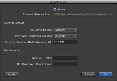
Chapter 9 EXS24 mkII 217
EXS24 mkII memory management
Multigigabyte sample libraries are commonplace today, delivering incredibly detailed and
accurate instrument sounds. In many cases, these sample libraries are too large to t into your
computer’s random-access memory (RAM). To use these huge sampler instruments, EXS24 mkII
can use a portion of your hard drive as virtual memory. When you turn on EXS24 mkII’s virtual
memory, only the initial attacks of audio samples are loaded into the computer’s RAM; the rest of
the sample is streamed in real time from the hard drive.
MainStage automatically addresses all available system memory. The amount of RAM available
for use by EXS24 mkII is determined by several factors, including:
•The amount of physical RAM installed in your computer.
•How much RAM other open applications and the operating system are using.
•How much RAM MainStage is using. This will vary in accordance with the number and size
of audio les in the project, and other plug-ins used. Sampler plug-ins not made by Apple, in
particular, can signicantly aect the amount of RAM that MainStage uses.
Virtual memory parameters
•Active checkbox: Turns on the EXS24 mkII virtual memory feature.
Note: If you have enough physical RAM to hold all the samples for a project, you will see
improved performance by deselecting the Active checkbox. In projects with lots of audio
tracks playing and relatively few EXS instances, this may aect performance. If the Active
checkbox is deselected and there is insucient RAM to hold all samples, MainStage swaps
data to and from the disk, which degrades performance. Deselecting the Active checkbox also
increases project load times, so you should leave it selected in most cases.
•Disk Drive Speed pop-up menu: Species the speed of your hard drive; if you have a solid-state
drive, or a 7200-rpm or faster hard drive for your audio samples, choose Fast. If you are using
a 5400-rpm laptop drive for your audio samples, choose Medium. You should not need to use
the Slow setting with any modern Mac.
•Hard Disk Recording Activity pop-up menu: Species overall hard disk usage—how much
recording and streaming of non-sampler-related audio is occurring. For example, if you are
recording an entire drum kit using over a dozen microphones, streaming live guitars and bass,
recording choirs, and so on, set your hard disk recording activity to Extensive. If your projects
consist mostly of software instrument playback, with perhaps a recorded instrument or vocal
or two, set your hard disk recording activity to Less. If you are unsure, choose Average.
Chapter 9 EXS24 mkII 218
•Requires Constant RAM Allocation Of eld: Shows the memory requirements of the above
parameters. The slower your hard drive and the higher your hard disk recording activity, the
more RAM you will need to allocate to virtual memory.
•Performance section: Shows the current disk I/O trac and the data not read from disk in time.
If these numbers start rising, EXS24 mkII may glitch when trying to stream samples from disk. If
you notice these values rising to high levels, change the general settings to free up additional
RAM for virtual memory use. If you continue to see high Performance display values and hear
audio glitches, consider installing more RAM in your Mac.
Open the Virtual Memory dialog
mIn the Parameter window, click the Options button, then choose Virtual Memory from the
pop-up menu.
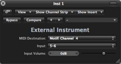
219
External Instrument overview
You can use the External Instrument to route external MIDI sound generators through the Mixer,
which you can then process with eects.
You can also use the External Instrument to transmit and receive MIDI information through the
instrument channel strip that it is inserted into. This enables you to control an external sound
module—both MIDI and audio—from within one element.
To avoid constant repatching of devices, it is best to use an audio interface that supports
multiple inputs and outputs. The External Instrument plug-in is inserted into instrument channel
strips in place of a software instrument.
External Instrument parameters
•MIDI Destination pop-up menu: Choose the target MIDI instrument and channel.
•Input pop-up menu: Choose the inputs of your audio hardware that the MIDI sound generator
is connected to.
•Input Volume slider and eld: Move to set the incoming signal level.
External Instrument 10
Chapter 10 External Instrument 220
Use the External Instrument
The track routed to an instrument channel strip that is being used for an external MIDI sound
module behaves just like a standard software instrument track. This enables you to record and
play back MIDI regions on it, with the following benets:
•You can use the sounds and synthesis engine of your MIDI module with no overhead on your
computer CPU apart from eects used in the channel strip.
•You can use insert and send eects. To use send eects, route the instrument channel strip to
aux channel strips.
•You can bounce external MIDI instrument parts, with or without eects, to an audio le in real
time. This makes the creation of a mix, including all internal and external devices and tracks, a
one-step process.
Note: Bouncing an External Instrument track cannot happen faster than real time, as is the case
with any bounce operation where MIDI hardware is involved.
When you use multitimbral MIDI sound sources, you can gain maximum exibility by using
multiple External Instrument instances. In this situation, connect a separate audio output of the
tone generator (if equipped with multiple outputs) to dierent inputs on your audio interface—
each addressed by individual External Instruments.
Process external MIDI instruments with eects
1 Connect the output (or output pair) of your MIDI module with an input (or input pair) on your
audio interface.
Note: These can be either analog or digital connections if your audio interface and MIDI sound
generator are equipped with either, or both.
2 Create an instrument channel strip.
3 Click the Instrument slot, then choose External Instrument from the pop-up menu.
4 Choose the MIDI Destination from the pop-up menu in the External Instrument window.
5 Choose the input (of your audio interface) that the MIDI sound generator is connected to from
the Input pop-up menu.
6 Adjust the Input Volume, if necessary.
7 Insert any required eects into the Insert slots of the channel strip (or channel strips, if you are
using multiple External Instrument instances with a multitimbral sound source).
You can also route the instrument channel strip to aux channel strips, if you want to use
send eects.
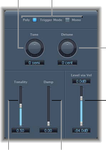
221
Klopfgeist parameters
Klopfgeist is an instrument that provides a metronome click. It is inserted into instrument
channel strip 256 by default and is used to generate the MIDI metronome click.
Klopfgeist can also be inserted into any other instrument channel strip for use as an instrument.
Damp slider
Tonality slider
Level via Vel slider
Detune knob
Trigger Mode buttonsTune knob
Klopfgeist has a number of synthesizer parameters that you can use to quickly create
metronome click sounds.
Klopfgeist parameters
•Trigger Mode buttons: Click Poly to use Klopfgeist as a four-voice polyphonic instrument. Click
Mono to use it as a monophonic instrument.
•Tune knob and eld: Rotate to tune Klopfgeist in semitone steps.
•Detune knob and eld: Rotate to ne-tune Klopfgeist in cents (one cent equals 1/100 of a
semitone).
•Tonality slider and eld: Drag to change the sound of Klopfgeist from a short click to a pitched
percussion sound—similar to a wood block or claves.
Klopfgeist 11
Chapter 11 Klopfgeist 222
•Damp slider and eld: Drag to set the release time. The shortest release time is attained when
Damp is at its maximum value, 1.00.
•Level via Vel slider and elds: Drag to set velocity sensitivity. The top slider sets the volume
at maximum velocity. The lower slider sets the volume at minimum velocity. Drag the area
between the two slider segments to move both simultaneously.
223
Retro Synth overview
Retro Synth is a exible 16-voice synthesizer that can produce a wide variety of sounds.
Retro Synth provides four types of synthesizer engines—Analog, FM, Sync, and Wavetable. Each
engine can generate unique sounds that are dicult, or impossible, to achieve with other types
of synthesizers.
Retro Synth is very easy to use, with many identical controls found in each synthesizer engine.
If you’re new to synthesizers, it might be best to start o with Synthesizer basics overview, which
will introduce you to the fundamentals and terminology of dierent synthesis systems.
The rst step in creating a new sound is to choose a Retro Synth synthesizer engine. Your choice
should be guided by the type of sound you want to generate.
Choose a synthesizer engine
mClick the tab of the synthesizer engine that you want to use:
•Analog: Use for classic synthesizer sounds, such as leads, pads, and basses. See Retro Synth
Analog oscillator controls.
•Sync: Use for aggressive synthesizer sounds, particularly leads and basses. See Retro Synth Sync
oscillator controls.
•Table: Use for synthesizer and real instrument sounds, or hybrids of these sound types. See
Retro Synth Table oscillator controls.
•FM: Use for classic digital synthesizer sounds. Of note are bells, electric piano, clavinet, and
spiky bass sounds. See Retro Synth FM oscillator controls.
Your choice of synthesizer engine changes the controls available. Most of these changes are seen
in the Oscillator section.
Retro Synth 12
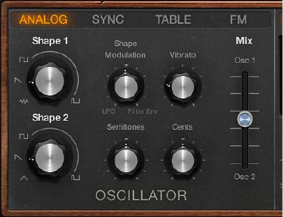
Chapter 12 Retro Synth 224
Retro Synth Analog oscillator controls
The synthesizer oscillators are used to generate one or more waveforms. You set the basic tonal
color with the chosen waveform or waveforms, adjust the pitch of the basic sound, and set the
level relationships between oscillators. The signal of one or both oscillators is then sent to other
parts of the synthesizer engine for shaping, processing, or manipulation. See Retro Synth lter
controls, Retro Synth amp and eect controls, Use Retro Synth modulation, and Retro Synth
global and controller settings.
Analog synthesizer sounds are typically attributed with having a warm and rich tone. You can
create a wide variety of timbres using this synthesis method, notably string and pad sounds,
synthetic brass, bass, and percussion.
Analog oscillator parameters
•Shape 1 and Shape 2 knobs: Rotate to choose the type of waveform that each oscillator
generates. The waveform is responsible for the basic tonal color.
•Analog engine: The oscillators output a number of standard waveforms—noise, rectangular,
sawtooth, and triangular.
•Table engine: You can choose from 100 waveforms, known as Digiwaves. Digiwaves are very
short samples of the attack transients of various sounds and instruments.
•Shape Modulation knob: Rotate to choose a waveform shape modulation source, and to set the
modulation intensity. The centered (o) position disables all waveform shape modulation with
the LFO or lter envelope.
•Vibrato knob: Rotate to set the amount of vibrato (pitch modulation).
•Semitones knob: Rotate to set the pitch of oscillator 2—in semitone steps, over a range of
±2 octaves.
•Cents knob: Rotate to precisely adjust the frequency of oscillator 2 in cents (1 cent = 1/100th
semitone).
•Mix slider: Move to crossfade (set the level relationships) between the oscillators (Shape 1 and 2).
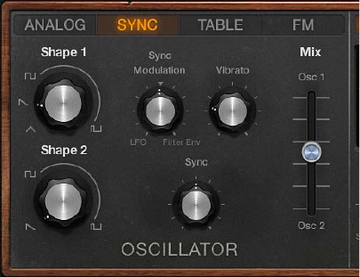
Chapter 12 Retro Synth 225
Retro Synth Sync oscillator controls
The synthesizer oscillators are used to generate one or more waveforms. You set the basic tonal
color with the chosen waveform or waveforms, adjust the pitch of the basic sound, and set the
level relationships between oscillators. The signal of one or both oscillators is then sent to other
parts of the synthesizer engine for shaping, processing, or manipulation. See Retro Synth lter
controls, Retro Synth amp and eect controls, Use Retro Synth modulation, and Retro Synth
global and controller settings.
Oscillator sync sounds are typically more aggressive than sounds generated with other synthesis
methods, making this engine most suitable for lead and hard bass instruments. The second
oscillator is resynchronized with the rst oscillator each time a note is triggered or each time the
waveform cycle of the rst oscillator restarts.
Sync oscillator parameters
•Shape 1 and Shape 2 knobs: Rotate to choose the type of waveform that each oscillator
generates. The waveform is responsible for the basic tonal color. The oscillators output a
number of standard waveforms—noise, rectangular, sawtooth, and triangular.
•Sync Modulation knob: Rotate to choose a sync modulation source, and to set the modulation
intensity. The centered (o) position disables all waveform modulation with the LFO or
lter envelope.
•Vibrato knob: Rotate to set the amount of vibrato (pitch modulation).
•Sync knob: Rotate to set the maximum amount of sync modulation. This makes the sound
more or less aggressive. Technically, this control changes the waveform start point of
both oscillators.
•Mix slider: Move to crossfade (set the level relationships) between the oscillators (Shape 1 and 2).
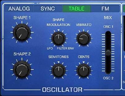
Chapter 12 Retro Synth 226
Retro Synth Table oscillator controls
The synthesizer oscillators are used to generate one or more waveforms. You set the basic tonal
color with the chosen waveform or waveforms, adjust the pitch of the basic sound, and set the
level relationships between oscillators. The signal of one or both oscillators is then sent to other
parts of the synthesizer engine for shaping, processing, or manipulation. See Retro Synth lter
controls, Retro Synth amp and eect controls, Use Retro Synth modulation, and Retro Synth
global and controller settings.
Wavetable synthesis is useful for creating evolving textures and more clinical sounds. It is well-
suited for pad creation, basses, and sound eects.
Table oscillator parameters
•Shape 1 and Shape 2 knobs: Rotate to choose the type of waveform that each oscillator
generates. The waveform is responsible for the basic tonal color.
•Analog engine: The oscillators output a number of standard waveforms—noise, rectangular,
sawtooth, and triangular.
•Table engine: You can choose from 100 waveforms, known as Digiwaves. Digiwaves are very
short samples of the attack transients of various sounds and instruments.
•Shape Modulation knob: Rotate to choose a waveform shape modulation source, and to set the
modulation intensity. The centered (o) position disables all waveform shape modulation with
the LFO or lter envelope.
•Vibrato knob: Rotate to set the amount of vibrato (pitch modulation).
•Semitones knob: Rotate to set the pitch of oscillator 2—in semitone steps, over a range of
±2 octaves.
•Cents knob: Rotate to precisely adjust the frequency of oscillator 2 in cents (1 cent = 1/100th
semitone).
•Mix slider: Move to crossfade (set the level relationships) between the oscillators (Shape 1 and 2).
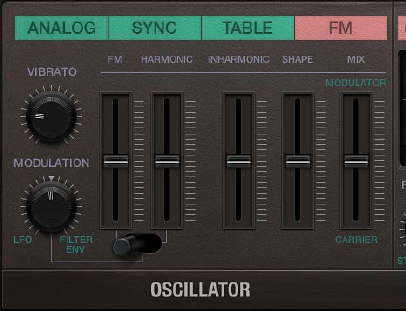
Chapter 12 Retro Synth 227
Retro Synth FM oscillator controls
The synthesizer oscillators are used to generate the basic tonal color. This signal is then sent to
other parts of the synthesizer engine for shaping, processing, or manipulation. See Retro Synth
lter controls, Retro Synth amp and eect controls, Use Retro Synth modulation, and Retro Synth
global and controller settings.
In FM synthesis, the basic sound is generated by setting dierent tuning ratios between the
modulator and carrier oscillators and by altering the FM intensity. The tuning ratio determines
the basic overtone structure, and the FM control sets the level of these overtones.
At the core of Retro Synth’s FM synthesis engine, you’ll nd a multiwave modulator oscillator—
the (Wave) Shape slider, and a sine wave carrier oscillator—the FM (Amount) slider. The basic
sine wave of the carrier oscillator is a pure, characterless tone.
To make things more sonically interesting, the modulator oscillator is used to modulate the
frequency of the carrier oscillator. This modulation occurs in the audio range (you can actually
hear it), and results in a number of new harmonics becoming audible, thus changing the
tonal color.
The pure sine wave (of the carrier oscillator) is combined with the newly generated harmonics,
making the sound much more interesting.
You can make ne changes to the tuning ratio of the two oscillators (and therefore the levels of
the harmonics) by adjusting the Harmonic and Inharmonic controls.
Chapter 12 Retro Synth 228
FM oscillator parameters
•Vibrato knob: Rotate to set the amount of vibrato (pitch modulation).
•Modulation knob: Rotate to choose an FM amount modulation source, and to set the
modulation intensity.
•FM (Amount) slider: The carrier waveform is a simple sine wave. Drag to adjust the level of this
basic tone.
•FM/Harmonic switch: Switch to control the harmonic/inharmonic content of your sound with
the LFO or Filter Envelope.
•The left switch position lets you use the LFO or Filter envelope to modulate the FM
(Amount).
•The middle switch position lets you use the LFO or Filter envelope to modulate the FM
(Amount) and Harmonic content at the same time.
•The middle switch position lets you use the LFO or Filter envelope to modulate the
Harmonic content.
•Harmonic/Inharmonic sliders: Drag the Harmonic and Inharmonic sliders to precisely change
the levels of these sonic elements, and therefore, the tonal color of your sound. Technically,
you are changing the tuning ratio between the carrier and modulator oscillators, resulting in
harmonic or inharmonic content becoming more or less audible.
Note: The tuning ratio can change signicantly when you adjust the (Wave) Shape slider,
so avoid using it if making a subtle alteration to the harmonic or inharmonic content of
your sound.
•(Wave) Shape slider: Drag to modulate the carrier waveform. This control and the FM slider
interact as you adjust either, resulting in a range of tones with more or less harmonic/
inharmonic content.
•Mix slider: Move to crossfade (set the level relationships) between the modulator and
carrier oscillators.
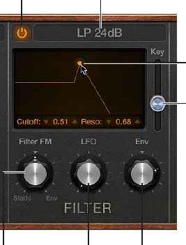
Chapter 12 Retro Synth 229
Retro Synth lter controls
Retro Synth features a exible lter that can operate as a lowpass, highpass, bandpass, band
reject, or peak lter. The lter can subtly, or dramatically, aect the basic tone sent from
the oscillators.
Filter use is straightforward. Choose a lter type and set a lter slope (if applicable). Adjust the
lter cuto and resonance controls to sculpt the sound. You can also control the lter cuto and
resonance controls while playing—either manually or by using keyboard position, an envelope,
or the LFO to modulate these lter controls automatically. Real-time changes to lter cuto and
resonance can make your performance much more dynamic and interesting. You can do this
with MIDI keyboard controllers and with the other lter section controls. See Use Retro Synth
modulation and Retro Synth global and controller settings.
On/off button
Key (Follow) slider
Filter FM knob LFO knob Filter Env(elope) knob
Filter Type pop-up menu
Cutoff/Resonance control
Filter parameters
•On/o button: Turns the lter section on or o. You will normally have the lter enabled
(indicated by the lit button at the top left of the lter section). Disable the lter when
adjusting other sound controls because this makes it easier to hear changes.
•Filter Type pop-up menu: Choose a lter type from the menu. There are four lowpass lters with
dierent slopes, a highpass, bandpass, band reject, and peak lter available.
•LP (lowpass): Allows frequencies that fall below the cuto frequency to pass. You can choose
one of four slopes that change the tonal characteristics of the lter, making it sound brighter,
mellow, thinner, or fuller—particularly in the bass end of the sound.
•HP (highpass): Allows frequencies above the cuto frequency to pass. The slope of the
highpass lter is xed at 12 dB/octave.
•BP (bandpass): The frequency band directly surrounding the cuto frequency is allowed to
pass. All other frequencies are cut. The Resonance control sets the width of the frequency
band. Bandpass is a two-pole lter with a slope of 6 dB/octave on each side of the band’s
center frequency.
•BR (band reject): The frequency band directly surrounding the cuto frequency is rejected,
but frequencies outside the band can pass. The Resonance control sets the width of the
rejected frequency band.
•Peak: A peak lter allows the level in a frequency band to be increased. The center of
the frequency band is set with the Cuto control. The width of the band is set with the
Resonance control.
Chapter 12 Retro Synth 230
•Cuto control: Drag the handle horizontally to set the brilliance of the signal.
•In a lowpass lter: the higher the Cuto frequency is set, the higher the frequencies of signals
that are allowed to pass.
•In a highpass lter: Cuto sets the point where low frequencies are suppressed.
•In a bandpass, band reject, or peak lter: Cuto sets the center frequency of the band that is
allowed to pass, is suppressed, or is emphasized.
•Resonance control: Drag the handle vertically to emphasize or suppress portions of the signal
above, below, or surrounding, the dened cuto frequency.
•Key (Follow) slider: Move to determine the eect that keyboard pitch (the note number) has on
lter cuto frequency modulation.
At the top position, the lter follows keyboard pitch, resulting in a constant relationship
between cuto frequency and pitch. This mirrors the properties of many acoustic instruments
where higher notes sound both brighter in tone and higher in pitch. At the bottom position,
the cuto frequency does not change, regardless of which key (pitch) you strike. This makes
the lower notes sound relatively brighter than the higher ones.
•Filter FM knob: Rotate to set the intensity of lter cuto frequency modulation with Oscillator
1’s sine wave generator. Positions to the left set the strength of static sine wave modulations.
Positions to the right set the strength of envelope-controlled sine wave modulations.
The centered (o) position disables lter frequency modulation by Oscillator 1’s sine
wave generator.
Note: Oscillator 1’s sine wave generator always generates a sine signal—at the frequency of
Oscillator 1.
•LFO knob: Rotate to set the strength of lter cuto frequency modulation with the LFO.
Positions further away from the centered (o) position make modulation more or less intense.
See Retro Synth LFO and Vibrato.
•Filter Env(elope) knob: Rotate to set the strength of lter cuto frequency modulation with the
Filter Envelope. Positions further away from the centered (o) position make modulation more
or less intense. See Retro Synth envelopes.

Chapter 12 Retro Synth 231
Retro Synth amp and eect controls
Retro Synth’s Amp controls set the overall volume. You can also mix a sine wave directly into
the output stage, which thickens the sound. You can make the sound richer with Retro Synth’s
integrated Chorus eect or add a sweeping, metallic character with the Flanger eect. If you’re
new to synthesizers and the concepts behind amp controls, see Synthesizer basics overview.
Volume knob
Sine Level knob
Mix knob
On/off button
Effect Type
pop-up menu
Rate knob
Amp parameters
•Volume knob: Rotate to set Retro Synth’s overall output level.
•Sine Level knob: Rotate to mix a sine wave at the frequency of oscillator 1 (Shape 1) directly
into Retro Synth’s output stage. This sine signal is not processed by the lter.
Eect parameters
•On/o button: Turns the eect section on or o.
•Eect Type pop-up menu: Choose either the Chorus or Flanger eect.
•The Chorus eect is based on a delay line, the output of which is mixed with the original,
dry signal. The short delay time is modulated periodically, resulting in pitch deviations.
The modulated deviations, in conjunction with the original signal’s pitch, produce the
chorus eect.
•The Flanger eect works in a similar fashion to the chorus, but with even shorter delay
times. The output signal is fed back into the input of the delay line. This feedback results in
the creation of harmonic resonances that cyclically move through the frequency spectrum,
resulting in a sweeping, metallic sound.
•Mix knob: Rotate to set the balance between the original and eect signals. High values result
in stronger eect processing.
•Rate knob: Rotate to set the modulation speed.
Tip: Use your host application eects if you need more precise control of chorus and anging or
want to use both eects simultaneously.
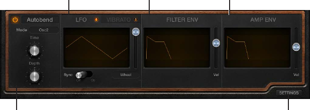
Chapter 12 Retro Synth 232
Retro Synth modulation controls
Use Retro Synth modulation
Retro Synth’s Glide/Autobend, LFOs, and envelopes are known as modulation generators. These
modulation sources are used to control modulation targets, such as oscillator pitch or lter cuto.
The Volume Envelope is dedicated to control of your sound’s level over time. The Filter Envelope
controls the lter over time. See Retro Synth envelopes.
Retro Synth’s LFO is used as a source for multiple modulation targets. The Vibrato modulation
source is dedicated to control of oscillator pitch. See Retro Synth LFO and Vibrato.
Glide—also known as portamento—and Autobend are hardwired to control oscillator pitch. See
Retro Synth Glide and Autobend.
You should make use of all modulation options because they can help you to create
expressive performances.
If you’re new to synthesizers and the concepts behind modulation generators, such as LFOs and
envelopes, see Synthesizer basics overview.
Click to switch between
modulation and
global/controller parameters.
Filter envelope Volume envelopeLFO
Autobend
Modulate the oscillator waveform
The Analog, Sync, and Wavetable oscillator waveform shapes can be modulated by following
these steps. In the FM synth engine, you can modulate the FM or Harmonic amount (or both).
1 Move the control toward LFO or Filter Env. Positions further away from the centered (o) position
make waveform modulation more intense.
2 Adjust the controls of the LFO (click the LFO tab if the Vibrato is visible) and Filter Env sections.
See Retro Synth LFO and Vibrato and Retro Synth envelopes.
3 If you are using the LFO, select a waveform.
4 If the (LFO) Sync switch is turned o:
•Adjust the Via Amount slider to the right of the waveform graphic to set the maximum
modulation intensity (the highest LFO speed).
•Move your MIDI keyboard’s modulation wheel to change the LFO speed. If you don’t want
to use your keyboard’s modulation wheel, click the Via pop-up menu to assign a dierent
MIDI controller.
5 If you are using the Filter Envelope, drag the handles to set the attack, decay, sustain, and release
values. Drag the Velocity slider to set the maximum amount of envelope modulation by velocity.
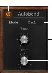
Chapter 12 Retro Synth 233
Use vibrato to modulate oscillator pitch
1 Rotate the Vibrato knob to set the amount of vibrato (pitch modulation).
2 Click the Vibrato tab if the LFO is visible.
3 Select a vibrato waveform.
4 If the Sync switch is turned o, drag the Rate note to set the vibrato speed. If the Sync switch
is turned on, vibrato speed is controlled by the host application tempo. See Retro Synth LFO
and Vibrato.
5 If the (Vibrato) Sync switch is turned o:
•Adjust the Via Amount slider to the right of the waveform graphic to set the maximum
modulation intensity (the highest vibrato speed).
•Move your MIDI keyboard’s modulation wheel to change the vibrato speed. If you don’t want
to use your keyboard’s modulation wheel, click the Via pop-up menu to assign a dierent
MIDI controller.
Retro Synth Glide and Autobend
In glide mode, the pitch of a played note slides to the pitch of the following played note.
Autobend automatically bends note pitches when you strike a key.
Glide mode behavior changes when legato is selected with the Voices control. See Retro Synth
global and controller settings.
On/off button
Bend Type
pop-up menu
Mode pop-up menu
Time knob
Depth knob
Glide/Autobend parameters
•On/o button: Turns the Glide/Autobend section on or o.
•Bend Type pop-up menu: Choose Glide or Autobend mode.
•Mode pop-up menu: Choose what you want to bend: Oscillator 1 + Sine, Oscillator 2, All
Oscillators, Opposed—with one oscillator bending up, while the other bends down by an
equal amount, or Oscillators + Filter.
•Time knob: Rotate to set the time it takes for the pitch of one played note to travel to the pitch
of another played note.
•Depth knob: (Autobend mode only) Rotate to set the pitch bend range (over a range of
±3 octaves).
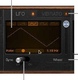
Chapter 12 Retro Synth 234
Retro Synth LFO and Vibrato
Retro Synth’s LFO (Low Frequency Oscillator) is a multiwaveform, polyphonic modulation
generator that modulates each voice, or note you play, individually. It can be used as a source for
multiple modulation targets.
Retro Synth also provides a dedicated Vibrato LFO for pitch modulation.
Although they are oscillators, LFOs are not audible—but their eects can certainly be heard. The
sole purpose of an LFO is to modulate other sound generating elements of the synthesizer.
LFO/Vibrato tabs
Rate slider
LFO Sync switch
Source pop-up menu
Waveform display
LFO/Vibrato parameters
•LFO/Vibrato tabs: Click to change LFO or Vibrato parameters.
•Waveform display: Click the buttons at the top of the display to independently choose an LFO
or Vibrato waveform.
•The sawtooth waves are suitable for bubbling, rhythmic eects.
•The triangle wave is suitable for vibrato and other evenly-modulated eects.
•The rectangular waves switch between two values, which is useful for stepping the oscillator
pitch by a fth, for example.
•LFO Sync button: Turn on to independently synchronize the LFO or Vibrato speed with the host
application tempo. Turn o to control the LFO or Vibrato speed manually.
•Rate slider: Drag to independently set the maximum LFO or Vibrato speed.
•Source pop-up menu: By default, your MIDI keyboard modulation wheel changes the LFO or
Vibrato speed (Rate slider). You can choose aftertouch or both aftertouch and your keyboard’s
modulation wheel to control the Rate parameter.

Chapter 12 Retro Synth 235
Retro Synth envelopes
Retro Synth features two identical attack, decay, sustain, and release (ADSR) envelopes that shape
the lter cuto and the level of the sound over time.
When you think of dierent sounds, such as a snare drum, piano, or strings, they’re not only
tonally dierent, but the characteristics of the sound change over time. Both the snare drum and
piano are heard immediately when struck. This is because they both have a short attack phase.
Bowed strings, on the other hand, slowly ramp up in level—they have a long attack time, in
other words.
If you break down any sound over time, you can emulate snare drum-like, piano-like, or string-
like characteristics easily with Retro Synth’s envelopes.
Attack handle
Vel(ocity) slider
Release handle
Decay/Sustain handle
Envelope parameters
•Attack handle: Drag horizontally to set the time it takes for the envelope to reach the
initial level.
•Decay/Sustain handle: Drag horizontally to set the time it takes for the envelope to fall to the
sustain level, following the initial attack time.
Drag vertically to set the sustain level, which is held until the key is released.
•Release handle: Drag horizontally to set the time it takes the envelope to fall from the sustain
level to a level of zero.
•Vel(ocity) slider: Drag to determine how sensitive the envelope is to incoming velocity.
•If set to maximum, the envelope outputs its maximum level only when the keys are struck at
maximum velocity.
•Softer velocities result in a corresponding change to the levels of each envelope—with a
50% velocity resulting in half-levels for the attack and sustain level parameters. Envelope
attack, decay, and release times are not aected by velocity modulation.
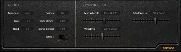
Chapter 12 Retro Synth 236
Retro Synth global and controller settings
Retro Synth global controls are used to set the overall tuning, polyphony, and other aspects of
your instrument.
The controller settings let you assign MIDI keyboard features to Retro Synth controls. You can use
three MIDI controllers—velocity, modulation wheel, and aftertouch—to change Retro Synth’s
Filter Cuto, Wave Shape (Pulse Width), or LFO/Vibrato Rate controls. Multiple MIDI controllers
can be assigned to the same Retro Synth control, so you could change lter cuto with both
velocity and aftertouch, for example. Alternatively, a single MIDI controller can be assigned to
multiple Retro Synth parameters—with aftertouch aecting both lter cuto and LFO speed,
for example.
If you’re new to synthesizers and the concepts behind modulation controls, see Synthesizer
basics overview.
Click the Settings label to switch between the modulation and global/controller controls.
Global parameters
•Transpose pop-up menu: Choose a value to transpose Retro Synth ±2 octaves.
•Tune eld: Click the arrows or drag vertically to tune Retro Synth in semitone steps.
•Bend pop-up menu: Choose a value to set the maximum upward/downward pitch bend. Pitch
bend modulation is typically performed with your MIDI keyboard pitch bend wheel or joystick.
•Voices pop-up menu: Choose a value to set the maximum number of notes that can be played.
Retro Synth can play up to 16 simultaneous voices, or can be used as a monophonic (single
voice) synthesizer.
•If you choose legato and play in a legato style (strike a new key while holding another),
the envelope generators are triggered only for the rst note you play legato, and then they
continue their curve until you release the last legato played key. This means that if you play
legato, a portamento occurs (the portamento time is set with the Autobend / Glide Time
control). If you release each key before pressing a new one, the envelope is not triggered by
the new note, and there is no portamento.
•If you choose mono, staccato playing retriggers the envelope generators every time a new
note is played.
•Voice Detune eld: Click the arrows or drag vertically to tune Retro Synth in cents
(1 cent = 1/100th semitone).
•Stereo Spread eld: Click the arrows or drag vertically to set the amount of voice panning,
respective to the center position. Spread: 0=mono, 1=full left/right panning. Voices are panned
left or right in an alternating, symmetrical pattern.
Note: Detuning and panning works in Single and Double voice mode. In Double voice mode,
detuning and panning aects the respective voice pairs.
Chapter 12 Retro Synth 237
•Double switch: Turns unison mode on or o. The behavior of unison mode depends on the
number of voices set with the Voices parameter. One of the strengths of polyphonic analog
synthesizers is unison—or stacked voices—mode. Traditionally, in unison mode classic analog
polysynths run monophonically, with all voices playing simultaneously when a single note is
struck. Because the voices of an analog synthesizer are never perfectly in tune, this results in a
rich, chorus-like eect with great sonic depth.
•Polyphonic unison mode: When 2–16 voices are selected, voices are stacked, but you can
play polyphonically.
•Monophonic unison mode: When Mono or Legato is selected with the Voices parameter, all
voices are stacked, but you can only play monophonically or in a legato style.
Controller parameters
•Mod Wheel to pop-up menu and slider: Choose a target for modulation with your keyboard’s
modulation wheel. Drag the slider to set the maximum modulation amount.
•Velocity to pop-up menu and slider: Choose a target for modulation with keyboard velocity.
Drag the slider to set the maximum modulation amount.
•Aftertouch to pop-up menu and slider: Choose a target for modulation with keyboard
aftertouch. Drag the slider to set the maximum modulation amount.
Retro Synth extended parameters
Retro Synth provides additional parameters that can be accessed by clicking the disclosure
triangle at the lower left of the interface.
Extended parameters
•MIDI Mono Mode pop-up menu: Choose O, On (with common base channel 1), or On (with
common base channel 16).
In either mode, each voice receives on a dierent MIDI channel. Controllers and MIDI messages
sent on the base channel aect all voices.
•Mono Mode Pitch Range pop-up menu: Choose 0, 24, or 48.
The chosen pitch bend range aects individual note pitch bend messages received on
all but the common base channel. The default is 48 semitones, which is compatible with
Mobile GarageBand's keyboard in pitch mode. When using a MIDI guitar, 24 semitones is the
preferable setting because most guitar to MIDI converters use this range by default.
238
Sculpture overview
This section contains key information and concepts that you need to understand before taking a
look at Sculpture features and parameters. If you’re new to synthesizers, it might be best to start
o with Synthesizer basics overview on page 472, which will introduce you to the terminology
and give you an overview of dierent synthesis methods and how they work.
Sculpture is a synthesizer that generates sounds by simulating the physical properties of a
vibrating string. This approach to tone generation is called component modeling. It enables you
to create a virtual model of an acoustic instrument, such as a violin or cello. Components such as
the length of the neck, the material the instrument is made of—wood or metal, for example—
the diameter, tension, and material of the strings—nylon or steel, for example—and the size of
the instrument body can be modeled.
In addition to the physical properties of the instrument, you can determine how and where it is
played—softly bowed, or plucked, on top of a mountain, or under the sea. Other aspects such as
nger noise and vibrato can also be emulated. You can even hit your virtual instrument’s strings
with a stick, or emulate dropping a coin onto the bridge.
Sculpture is not limited to recreating real-world instruments. You are free to combine
components in any way, leading to bizarre hybrids such as a six-foot-long guitar with a bronze
bell for a body—played with a felt hammer.
You can also create more traditional synthesizer tones in Sculpture. These benet from the
modeling process itself, which tends to add a level of richness and an organic quality to sounds.
The end results are lush, warm pads, deep and round synthesizer basses, and powerful lead
sounds. If you need to create an endlessly evolving texture for a lm soundtrack, or a spaceship
takeo sound, Sculpture is the perfect instrument for the job.
Like a real instrument, Sculpture generates sounds by using an object, such as a ngertip, wind,
drumstick, or violin bow, to stimulate another object, such as a guitar string or reed.
Note: For clarity, the stimulated object is always referred to as the string.
As with a real instrument, the sound consists of multiple elements. It’s not only the string that is
responsible for the tonal color, but also the objects that stimulate or otherwise aect the string,
and therefore the sound.
For example, imagine a steel-stringed guitar that is alternately strummed with your thumb
and then picked strongly with your ngers. Changing to nylon strings, or 12 strings, would
signicantly change the tone. Now imagine the impact of pressing the strings down onto
the fretboard, which not only changes the chord but also momentarily bends the strings, and
therefore their pitch. Other aspects to consider are the size and material of the guitar body and
how they inuence the resonant characteristics of your sound. Further elements, such as the size
or type of sound hole—round or F-shaped—the nger noise on the strings, and the medium
that the guitar is played in, also have roles to play in the overall sound that you produce.
Sculpture 13
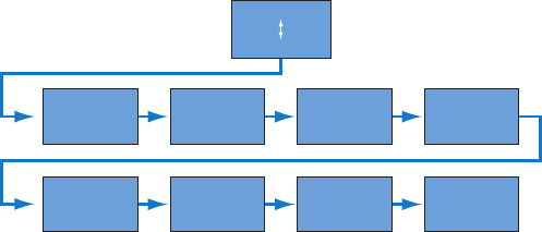
Chapter 13 Sculpture 239
Sculpture enables you to virtually model the physical consistency and behavior of all
components involved—hence component modeling synthesis.
Limiter
Level
Body EQ
Delay
Filter
Wave
Shaper
Amplitude
envelope
Pickups
String
Objects
This gure shows the signal ow of Sculpture’s core synthesis engine.
Following the stimulation of the string by various objects, the vibration of the string is captured
by two movable pickups—you can view these as being similar, in concept and operation, to the
electromagnetic pickups found on guitars, electric pianos, or clavinets.
The pickups send the signal to the ADSR-equipped amplitude stage, a Waveshaper module, and
a multimode lter. These all serve to sculpt your sound.
Note: All elements described above exist on a per voice basis.
The sum of all voice signals can then be processed by an integrated delay eect. From there,
the signal is sent to an EQ-like module (the Body EQ), which simulates the spectral shape/body
response of your instrument. The resulting signal is then fed to a level limiter section.
A vast number of modulation sources are also available, from tempo-synced LFOs to jitter
generators and recordable envelopes. These can control the string and object properties, the
lter, and other parameters. You can even modulate other modulation sources.
A recordable morph function also allows for smooth or abrupt transitions between up to ve
morph points. A morph point is essentially a collection of parameter settings at a given moment
in time.
Important: The interaction between various sections of the component modeling synthesis
engine is more dynamic and more tightly intertwined than that of other synthesis methods. This
can lead to some truly unique sounds, but sometimes even a small parameter change can deliver
dramatically dierent, and unexpected, results. Sculpture requires a more measured approach to
sound creation than a traditional synthesizer design. Refer to the owchart while learning the
interface and programming.
Sculpture is a performance-oriented synthesizer that benets from the use of controllers,
modulations, and dierent playing techniques. Take time to experiment with all available controls
and parameters when you initially audition some of the supplied sounds, and when you create
new ones of your own.
Several tutorial sections will help you learn about creating sounds with Sculpture.
•Explore Sculpture overview on page 290
•Basic sound programming overview on page 295
•Electric bass programming overview on page 305
•Synthetic sound programming overview on page 323
•Explore Sculpture modulation options on page 294
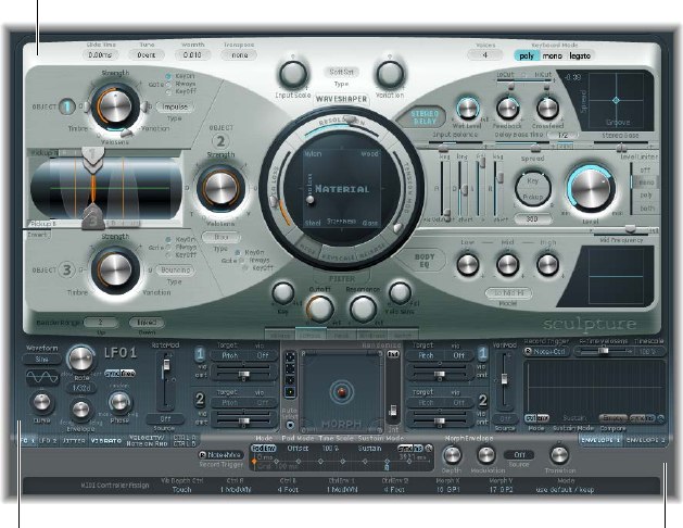
Chapter 13 Sculpture 240
Sculpture is an instrument that requires some investment of your time, but it will reward you
with beautifully warm and organic sounds, evolving soundscapes—or a harsh and metallic “Hell’s
Bells” patch, if required. Don’t be afraid to experiment; that’s what Sculpture was created to do.
Sculpture interface
Sound engine
Modulation section Global control sources
The user interface of Sculpture is divided into three main areas.
•Sound engine: The top two-thirds of Sculpture contains the sound engine. It is divided into ve
subsections:
•String parameters: The circular Material Pad in the center is used to create and control the
string, thus determining the basic timbre of your sound.
•Object parameters: The area at the top left contains the objects that are used to stimulate or
otherwise aect the string in some way.
•Processing parameters: The processing parameters capture the string signal and provide
further tonal control. These include the lter, Waveshaper, pickup, and amplitude
envelope parameters.
•Global parameters: Aect the overall behavior of Sculpture. Global parameters include bend
range, keyboard mode, and tuning controls.
•Post-Processing parameters: Aect the overall tone and behavior of the entire instrument.
Post-processing parameters include the Delay, Body EQ, and Level Limiter parameters.
•Modulation section: The blue/gray area below the sound engine contains the modulation
sources—LFOs, jitter generators, and recordable envelopes.
•Global control sources: The area at the bottom of the interface enables you to assign MIDI
controllers to Sculpture parameters. This section also incorporates the Morph Pad, a dedicated
controller for morphable parameters.
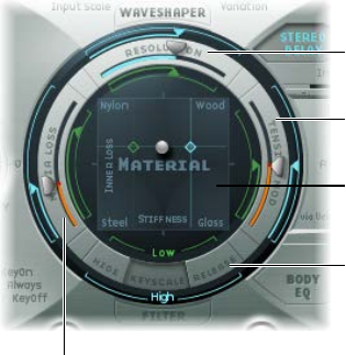
Chapter 13 Sculpture 241
Sculpture string parameters
Sculpture string overview
The string is responsible for the basic tone of your sound. You can dene its material—what it’s
made of—and determine its behavior when bowed, plucked, struck, and so on.
The string itself doesn’t make a sound unless it is stimulated—excited or disturbed—by at least
one object. Up to three dierent types of objects are used to excite, disturb, or damp the string
(make it vibrate or aect its movement). See Sculpture objects overview on page 247.
Sculpture’s string and the excite/disturb objects are similar to the oscillators in traditional
synthesizers. The string is considerably more sophisticated in concept than simple oscillators,
however.
In essence, you are creating the waveform, or base timbre, by mathematically describing the
string’s properties, and the properties of its environment. These include, among others, the
material the string is made of; the thickness, length, and tension of the string; its characteristics
over time; the atmosphere it is being played in (such as water or air); and the way it is being
played—struck, bowed, and so on.
Sculpture goes far beyond the mere creation of an innite number of base timbres, however.
One of the key dierences between Sculpture’s string and a traditional synthesizer waveform
is that the base timbre provided by the string is in a constant state of ux. For example, if
Sculpture’s string is still vibrating for a specic note, retriggering that same note will interact
with the ongoing vibration. This is not dissimilar to the eect of repeatedly plucking a guitar
string, where the string is still vibrating when the next note is played. This will alter the harmonic
spectrum each time—which is why acoustic guitars sound organic when a note is played
repeatedly, and sampled guitars don’t.
This is quite dierent from other synthesis methods where the base timbre waveform, even if
modulated, does not harmonically interact with currently audible notes when retriggered. What
usually happens in traditional synthesizers is that the waveform is restarted—from mid-cycle, or
from the beginning—with the result being an increase in volume, or a slight cyclical wave shift.
The string parameters apply on a per-voice basis. You will note a number of parameter names
followed by (morphable). This indicates that the parameters can be morphed between up to ve
morph points. See Sculpture morph overview on page 280.
Media Loss sliders
Hide, Keyscale, and
Release View buttons
Tension Mod(ulation)
sliders
Material Pad
Resolution sliders
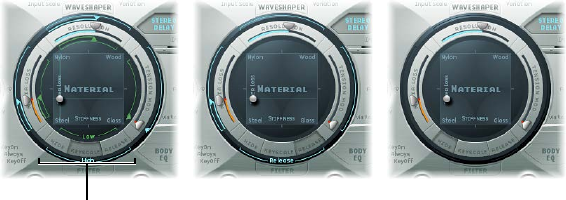
Chapter 13 Sculpture 242
String parameters
•Hide, Keyscale, and Release view buttons: Show or hide dierent groups of parameters.
•Material Pad: Determines the basic tone of the string by setting the stiness and
damping properties.
•String parameter sliders: Shown on the outer ring of the Material Pad, the String parameter
sliders further dene the properties and behavior of the string.
•Resolution sliders: Determine the maximum number of harmonics contained in the sound at
C3 (middle C). Spatial resolution is also changed.
•Media Loss sliders: Emulate the amount of string dampening caused by the surrounding
environment (air, water, and so on) at C3 (middle C).
•Tension Mod(ulation) sliders: Determine the momentary detuning of the sound at C3
(middle C).
All sliders are set relative to middle C. As you play above or below this note, tuning and other
elements of the string can, and will, change.
Sculpture Hide, Keyscale, and Release view
Click the Keyscale, Release, or Hide button to show or hide the corresponding parameters in the
ring surrounding the Material Pad.
Click these buttons to
activate or hide the
Keyscale or Release
parameters.
Keyscale view Release view Hide view
Hide, Keyscale, and Release parameters
•Hide button: Hides several elements, simplifying the interface and making it impossible to
accidentally change Key Scale or Release parameters.
•Keyscale button: Sets parameters for notes that fall below C3, or notes that are positioned
above it. In simple terms, the impact of these parameters can be controlled across the
keyboard range. For example, a parameter such as string Stiness could be more intense
for high notes and less intense for low notes. In practical terms, this would result in more
harmonic (sweeter) sounding bass notes and inharmonic overtones in treble notes (notes
above C3).
•Release button: Turn on to set string Release parameters, which aect the vibrations of the
string after the key is released.

Chapter 13 Sculpture 243
Sculpture’s basic Material Pad parameters
The Material Pad works as a matrix of Stiness (x-axis) and Inner Loss (y-axis) values.
Stiffness axis
Material Pad ball
Inner Loss axis
The four corners of the Material Pad display dierent material names. These each represent a
combination of maximum/minimum Stiness and Inner Loss values. The combination of the
Inner Loss and Stiness parameter positions determine the string material and, therefore, the
general timbre of your sound. Here are examples of how Inner Loss and Stiness settings can
change the tonal color:
•Low Stiness values, combined with low Inner Loss values, lead to metallic sounds.
•Higher Stiness values, combined with low Inner Loss values, make the sound become more
bell-like or glass-like.
•Higher Inner Loss values, combined with a low Stiness level, correspond to nylon or
catgut strings.
•High Stiness values, combined with high Inner Loss values, simulate wood-like materials.
Material Pad parameters
•Inner Loss: Emulates damping of the string caused by the string material—steel, glass, nylon, or
wood. These are frequency-dependent losses that cause the sound to become more mellow
during the decay phase.
•Stiness: Sets the rigidity of the string. In reality, this is determined by the string material
and diameter—or, to be more precise, by its geometrical moment of inertia. Increasing the
Stiness parameter to the maximum value turns the string into a solid metal bar. Stier strings
also exhibit an inharmonic vibration, where overtones are not integer multiples of the base
frequency. Rather, they have higher frequencies, which can make upper/lower notes sound
somewhat out of tune with each other.
•Material Pad ball: Controls both the Inner Loss and Stiness parameters simultaneously when
you drag it within the Material Pad. The ball marks a specic point on the X and Y planes.
Note: The thickness of the string—the green horizontal line in the Pickup display—changes as
you move the ball. See Use Sculpture’s string parameter sliders on page 245

Chapter 13 Sculpture 244
Use Sculpture’s Material Pad in Keyscale or Release view
In Keyscale or Release view, the Material Pad shows additional controls for the Keyscale and
Release parameters.
Diamond control
Crosshair control Line control
Diamond control
Keyscale view Release view
Material Pad Keyscale and Release parameters
•Diamond controls: Drag to adjust the Stiness and Inner Loss Keyscale and Release parameters.
•In Keyscale view, the diamonds indicate the intersection between the Inner Loss and
Stiness Low/High Scaling positions. You can drag these diamonds to adjust both
parameters simultaneously.
•In Release view, you only drag the diamond vertically, because you cannot adjust the release
behavior of the Stiness parameter.
•Crosshair and line controls: Use to control the Keyscale and Release parameters when the
diamonds are hidden by the ball. The crosshair also enables you to independently change the
keyscaling for one of the two axes (X/Y positions, which control the current Inner Loss and
Stiness values).
Note: Option-click any of the controls to reset parameters to their default values.
Adjust Inner Loss key scaling in the Material Pad
The Inner Loss Keyscale parameters control the amount of damping—independently for notes
above and below middle C. This changes the way damping is scaled as you play lower or higher
on the keyboard.
1 Click the Keyscale button.
2 Drag the green horizontal line for low notes or the blue horizontal line for high notes.
Adjust Stiness key scaling in the Material Pad
The Stiness Keyscale parameters adjust the string stiness—independently for notes above and
below middle C. This changes the scaling of inharmonic content that is heard as you play lower
or higher on the keyboard.
1 Click the Keyscale button.
2 Horizontally drag the green vertical line for low notes or the blue vertical line for high notes.
Tip: You can simultaneously adjust both Stiness and Inner Loss key scaling by dragging the
diamond that intersects the green lines.
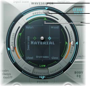
Chapter 13 Sculpture 245
Adjust Inner Loss release scaling in the Material Pad
In Release view, you dene changes to the damping amount when the key is released.
Conservative use of this parameter—in conjunction with Media Loss Scale Release—allows a
natural simulation of strings that are dampened when a note-o message is received. See Use
Sculpture’s string parameter sliders on page 245.
1 Click the Release button.
2 Vertically drag the blue Release line.
Use Sculpture’s string parameter sliders
The sliders on the outer ring of the Material Pad further dene the properties and behavior of
the string.
Material Pad in Keyscale view
Resolution slider
Resolution High Scaling
slider
Resolution Low Scaling
slider
String parameter sliders
•Resolution slider: Drag to set the maximum number of harmonics contained in (and spatial
resolution of) the sound at C3. Changes to the Resolution value alter the interaction of the
string with the objects, which has a corresponding eect on overtone frequencies—very low
Resolution values result in inharmonic spectra, even with Stiness set to 0. Higher resolution
values enhance the precision of calculations, increasing computer processing requirements. In
Keyscale view, the Resolution High and Low Scaling sliders are shown:
•Resolution High Scaling slider (blue): Drag to set the key tracking resolution—the accuracy of
key tracking—for notes above middle C (C3).
•Resolution Low Scaling slider (green): Drag to set the key tracking resolution for notes below
middle C.
•Media Loss slider: Drag to set the amount of string damping caused by the surrounding media
(the atmosphere)—for example, air, water, olive oil, and so on. These losses are independent
of frequency. This provides control over the duration of the exponential amplitude decay, after
the excitation of the string has stopped.
•Media Loss High Scaling slider (blue): In Keyscale view, sets the key tracking resolution for
notes above middle C (C3). In Release view, it sets media loss behavior when the key
is released.
•Media Loss Low Scaling slider (green): In Keyscale view, sets the key tracking resolution for
notes below middle C. In Release view, it sets media loss behavior when the key is released.
Chapter 13 Sculpture 246
•Tension Mod slider: Drag to set the momentary detuning of the string.
•Tension Mod High Scaling slider (blue): Drag to set the tension modulation behavior for notes
above middle C.
•Tension Mod Resolution Low Scaling slider (green): Drag to set the tension modulation
behavior for notes below middle C.
Note: This nonlinear eect can deliver surprising results and can also make the entire
model unstable, especially when combined with low Media Loss and Inner Loss values. If
your sound spikes or drops out during the decay phase, try reducing Tension Mod, and
perhaps Resolution.
Adjust Resolution key scaling
1 Click the Keyscale button.
2 Drag the green low slider inside the top of the Material Pad ring for low notes—or the blue high
slider around the top of the outer ring for high notes.
Adjust Media Loss key scaling
1 Click the Keyscale button.
2 Drag the green slider inside the left side of the Material Pad ring.
Adjust the Media Loss release time
1 Click the Release button.
2 Drag the blue slider in the outer ring at the left side of the Material Pad.
Values above 1.0 cause media losses to increase when the key is released. This parameter can be
used to simulate a string that is dropped into a bucket of water after initially vibrating in air, for
example. Obviously, this is not what the average violinist or pianist would do, but it can be useful
for some interesting sound variations.
Adjust Tension Mod key scaling
Strings, such as those of a guitar, exhibit a particularly prominent nonlinear behavior—if the
string excursion is large, the string is detuned upward. Because this detuning is caused by the
momentary, rather than the average, excursion of the string, the detuning occurs very quickly.
This phenomenon is known technically as tension modulation nonlinearity. Nontechnically, setting
or modulating the Tension Mod slider to values above 0.0 emulates this momentary detuning
eect in Sculpture.
1 Click the Keyscale button.
2 Drag the green low slider inside the right side of the Material Pad ring for low notes—or the blue
high slider around the right side of the outer ring for high notes.
Tip: If your instrument seems slightly sharp or at as you play up or down the keyboard, consider
adjustments to the Tension Mod, and perhaps Media Loss, Keyscale parameters.
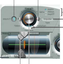
Chapter 13 Sculpture 247
Sculpture objects parameters
Sculpture objects overview
The objects are used to stimulate or otherwise aect the string in some way. The object
parameters discussed in this section apply on a per-voice basis. You will note a number of
parameter names followed by (morphable). This indicates that the parameters can be morphed
between up to ve morph points. For more information, see Sculpture morph overview on
page 280.
Important: At least one object must be used to excite or disturb the string, because the string
itself does not make any sound.
There are a number of dierent string excite/disturb/damp models available, such as blow, pluck,
bow, and so on. These can radically alter the general timbre of the string’s attack phase, making
it possible to create bowed or plucked ute and bell sounds, or guitars with a ute-like attack,
for example.
Judicious use of the object parameters can deliver very accurate emulations of real-world
instruments, or sounds that are altogether more other-worldly.
It is important to note that each additional disturb/damp object that is activated will aect the
string. This will, in turn, alter the interaction of any other active object with the string, often
resulting in a completely dierent sonic character.
The goal of changing your sound’s character is the reason you would use a new object, but
the pluck and blow object combination you chose may sound like ngernails on a blackboard,
rather than the plucked pan ute you were trying to create—depending on other string settings.
Therefore, you need to pay special attention to the model type and strength of objects. You may
nd that the avor of the excite object (Object 1), for example, has changed signicantly—and
you may need to adjust or change the parameters of all objects (and perhaps several string
parameter values) after you introduce a new disturb/damp object (2 or 3). Similarly, the selection
of a dierent type of excite object will aect the disturb/damp objects—and the string itself—
thereby changing the character of your sound.
Repositioning objects also changes the timbre of the string. If you are emulating a guitar, for
example, changing an object position would be similar to picking or strumming a string at
various spots along the fretboard.
On/Off button
Gate mode buttons
Type pop-up menu
Variation slider
Velo(city) Sens(itivity) slider
Strength knob
Timbre slider

Chapter 13 Sculpture 248
Object parameters
•On/O buttons (1, 2, and 3): Turn the object on or o.
•Type pop-up menus: Choose each object type. See Sculpture excite table (objects 1 and 2) on
page 248 and Sculpture disturb and damp table (objects 2 and 3) on page 250.
•Gate mode buttons: Click to determine when the object is active—that is, when it disturbs or
excites the string. You can choose from:
•KeyOn: Between note-on and note-o
•Always: Between note-on and the end of the release phase
•KeyO: Triggered at note-o, and remaining active until the voice is released
Note: Some object types, such as Gravity Strike, may retrigger the note when you release
a key—when in Key On gate mode. If you encounter this artifact, try setting gate mode to
Always, or reduce the Strength of the object.
•Strength knob (morphable): Rotate to set the intensity of the excitation/disturbance (depending
on type). A value of 0.0 eectively disables excitation/disturbance. In contrast to the On/
O button of each object, you can fade in the Strength parameter with modulation or
morphing options.
•Timbre slider (morphable): Determines the timbre (tonal color) of the chosen excitation/
disturbance type. Zero (0.0) is the default value for the object. Positive values make the sound
brighter. Negative values lead to a more mellow sound.
•Variation slider (morphable): An additional timbre parameter, which is also type dependent.
•VeloSens slider (Objects 1 and 2 only): Enables you to reduce velocity sensitivity to 0. Excite
objects are velocity sensitive, but this may not be appropriate for all sounds, which is where
this parameter is useful.
Note: An object is velocity sensitive only when a type that actively excites the string is
selected. The Velocity Slider is available only for objects that are velocity sensitive. Object 1 is
velocity sensitive. Object 2 can be both, depending on the object type you choose. Object 3 is
not velocity sensitive.
Sculpture excite table (objects 1 and 2)
Before you look at the tables of object types and properties, you should note the following:
•Object 1 can only use the excite types found in the rst table.
•Object 2 can use the excite and disturb/damp types available in both tables.
•Object 3 can only use the disturb/damp types found in the second table. See Sculpture disturb
and damp table (objects 2 and 3) on page 250.
The following table lists all excite types available for Objects 1 and 2, and information about the
controls available for each object type.
Name Description Strength controls Timbre controls Variation controls
Impulse A short impulse
excitation
Impulse amplitude Width Velocity
dependence of
width
Strike Short excitation,
like a piano
hammer or mallet
Hammer start
speed (velocity
dependent)
Hammer mass Felt stiness

Chapter 13 Sculpture 249
Name Description Strength controls Timbre controls Variation controls
GravStrike Like hammer but
with gravitation
toward the string,
leading to multiple
hammer-string
interactions and
disturbed string
vibrations
Hammer start
speed
Felt stiness Gravitation
Pick Finger or plectrum
picking
Pickup force and
speed
Force/speed ratio Plectrum stiness
Bow Bowing of the
string
Bow speed Bow pressure Slip stick
characteristics
Bow wide Same as bow, but
wider, resulting in a
more mellow tone,
especially suited
for smooth bow
position changes
Bow speed Bow pressure Slip stick
characteristics
Noise Noise injected into
the string
Noise level Noise bandwidth/
cuto frequency
Noise resonance
Blow Blow into one end
of the string (an air
column, or tube). At
various positions,
starting from 0.0
(far left), move the
blowing direction
and position from
along the string
toward one end.
The string is blown
sideways at the
chosen position.
Lip clearance Blow pressure Noisiness
External (available
only for Object 2)
Feeds side-chain
signal into string.
Level Cuto frequency of
lowpass lter being
used to process
side-chain signal
Width (size) of the
string area being
aected by the
side-chained signal

Chapter 13 Sculpture 250
Sculpture disturb and damp table (objects 2 and 3)
The following table lists all disturb and damp types available for Objects 2 and 3. For information
on excite types available for Objects 1 and 2, see Sculpture excite table (objects 1 and 2) on
page 248.
Name Description Strength controls Timbre controls Variation controls
Disturb A disturb object
that is placed at a
xed distance from
the string’s resting
position
The hardness of the
object
The distance from
the resting position
•Negative
values: Push
the string away
from the resting
position.
•Positive
values: Do not
aect the string
in the resting
position.
Controls width.
•Negative
values: Aect
only a small
section of the
string.
•Positive
values: Aect a
broader section
of the string.
Disturb 2-sided Somewhat like a
ring placed around
the string, which
limits the string’s
vibration in all
directions
The hardness of
the ring
The clearance
of the ring (the
distance between
the ring and string)
•Negative
values: The sides
of the damping
ring overlap,
inuencing
the string if
any movement
occurs.
•Positive
values: There
is an amount
of clearance
inside the ring.
The string will
be inuenced
only if moved
suciently to
actually touch
the ring.
No eect
Bouncing Emulates a loose
object lying or
bouncing on, and
interacting with,
the vibrating string.
This is very random
by nature and can’t
be synchronized.
Controls the gravity
constant for the
object lying/
bouncing on the
string.
The stiness of the
object
The damping of the
object

Chapter 13 Sculpture 251
Name Description Strength controls Timbre controls Variation controls
Bound A boundary that
limits and reects
string movement.
This is much like
a ngerboard
that limits string
movement when
the string is
plucked very rmly.
The distance from
the boundary
center position to
the string’s resting
position
The slope
(steepness) of the
boundary. A value
of 0.0 places the
boundary parallel
to the string. Other
values will position
the boundary
closer to the string
on one end and
farther away on the
other.
The amount of
reection at the
boundary limits
Mass Used to model an
additional mass
attached to the
string. This can
lead to inharmonic
sounds, and very
interesting results,
if the position
of this mass is
modulated along
the string.
The mass size/
weight
No eect No eect
Damp Localized damper,
which is useful for
soft damping
The intensity of the
damping
The damping
characteristics
The width of the
damped string
section
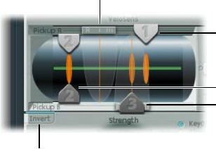
Chapter 13 Sculpture 252
Sculpture pickups parameters
Use Sculpture pickup parameters
The pickup parameters discussed in this section apply on a per-voice basis. You will note a
number of parameter names followed by (morphable). This indicates that the parameters can be
morphed between up to ve morph points. See Sculpture morph overview on page 280.
The pickups are the rst element beyond the sound-generating portion of Sculpture—consisting
of the string and objects—and act as the input to the virtual signal processing chain. You can
view the pickups as being like those of an electric guitar or clavinet. Obviously, changing their
positions alters the tone of your instrument, just like the pickups in Sculpture.
Pickup A position slider
Invert button
Object position slider
Object position slider
Object position slider
The green horizontal line within the Pickup display represents the string. As the Stiness
parameter value of the string is increased, the line becomes thicker. The line can be animated
and will show the range of the string’s motion.
The Pickup A and B ranges are shown as transparent bell curves, which represent the position
and widths of pickups A and B.
Pickup parameters
•Object position sliders (morphable): Drag sliders 1, 2, and 3 to determine the respective position
of each (excite/disturb/damp) object along the string.
•Pickup A position slider (morphable): Drag to set the position of Pickup A along the string. Values
of 0.0 and 1.0 determine the left and right ends of the string, respectively.
•Pickup B position slider (morphable): Drag to set the position of Pickup B along the string,
shown underneath Object position slider 3 at the bottom of the gure.
•Invert button (Pickup B phase): Click to invert the phase of Pickup B, found at the lower left of
the Pickup display. Options are: normal or invert(ed).
Note: If the phase of Pickup B is inverted, the sound can become thinner due to portions of
the Pickup A and Pickup B signals canceling each other out. Depending on the position of the
pickups, however, the reverse may happen, with the sound actually becoming richer.
Adjust the Pickup A or Pickup B position
mDrag the slider handle at the top or bottom of the Pickup display.
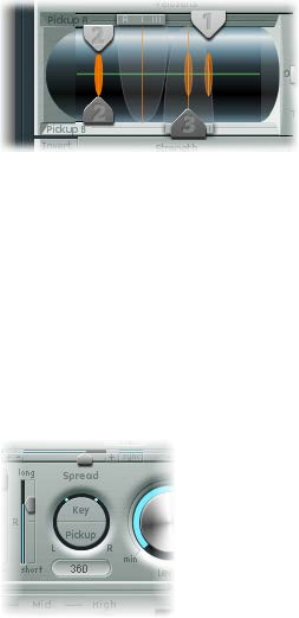
Chapter 13 Sculpture 253
Adjust an object pickup position
mDrag the corresponding numerical slider handle (the 1, 2, or 3 arrows) for each object.
Adjustments to object positions will disturb/excite a given portion of the string. The vertical
orange lines represent the positions of Objects 1, 2, and 3. The thickness and brightness of these
lines indicate the strength of the objects. Object 1 can be an exciter. Object 3 can be a damper.
Object 2 has two arrows, indicating that it can be used as either an exciter or damper.
Turn string animation on or o
mControl-click the green horizontal line—the string—to enable or disable string animation.
When animation is active, the string vibrates, making it easier to visualize the impact of the
objects and pickups. Note that string animation increases CPU overhead, so disable it if your
computer is struggling to process all data in real time.
Sculpture’s spread controls
Although they are not found in the actual Pickup display, two additional pickup parameters are
available to the right of the Material Pad.
Key/Pickup Spread parameters
•Key Spread button: Drag vertically to set the amount of panning (pan position) by MIDI note
number. Depending on settings, the farther up or down the keyboard you play, the more
the voice is panned left or right. Two lines in the ring that surrounds the Spread parameters
indicate values.
•Pickup Spread button: Drag vertically to spread the two pickups across the stereo base. Two
dots in the ring that surrounds the Spread parameters indicate values.
Tip: You can create animated width and chorus eects by modulating the Pickup Position
parameters with an LFO or other modulator.
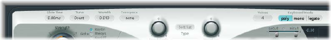
Chapter 13 Sculpture 254
Sculpture global parameters
These are found across the top of the Sculpture interface, unless otherwise specied.
Global parameters
•Glide Time eld: Drag to set the time required to slide from the pitch of one played note to
another. The Glide parameter behavior depends on the keyboard mode you choose.
•If you set the keyboard mode to Poly or Mono and set Glide to a value other than 0,
portamento is active.
•If you choose Legato and set Glide to a value other than 0, you need to play legato (press
a new key while holding the old one) to activate portamento. If you don’t play in a legato
style, portamento won’t work. This behavior is also known as ngered portamento.
•Tune eld: Drag to ne-tune the entire instrument, in cents. A cent is 1/100th of a semitone.
•Warmth eld: Drag to slightly detune each voice, much like the random uctuations caused by
the components and circuitry of analog synthesizers. As the parameter name suggests, this
warms up or thickens the sound.
•Transpose eld: Drag to tune the entire instrument by octaves. Given the ability of
component modeling to radically alter pitch with certain settings, coarse tuning is limited to
octave increments.
•Voices eld: Drag to specify the number of voices that can be played at any one time. Sixteen
voices is the maximum polyphony of Sculpture.
•Keyboard Mode buttons: Click to choose polyphonic, monophonic, and legato behaviors.
A polyphonic instrument, such as an organ or piano, allows several notes to be played
simultaneously. Many older analog synthesizers are monophonic, which means that only one
note can be played at a time, much like a brass or reed instrument. This shouldn’t be viewed
as a disadvantage in any way, because it allows playing styles that are not possible with
polyphonic instruments.
•In Mono mode, staccato playing retriggers the envelope generators every time a new note
is played. If you play in a legato style (play a new key while holding another), the envelope
generators are triggered only for the rst note you play legato. They then continue their
curve until you release the last legato played key. Mono mode is also known as multi
trigger mode.
•Legato mode is also monophonic, but with one dierence: the envelope generators are
retriggered only if you play staccato—releasing each key before playing a new key. If you
play in a legato style, envelopes are not retriggered. Legato mode is also known as single
trigger mode.
Note: All modes retrigger a potentially sounding voice with the same pitch, instead of
allocating a new one. Therefore, multiple triggering of a given note results in slight timbral
variations, depending on the current state of the model at note-on time. If Sculpture’s string
is still vibrating for a specic note, retriggering that same note interacts with the ongoing
vibration, or current state of the string. A true retrigger of the vibrating string will happen only
if both Attack sliders of the amplitude envelope are set to 0. If either slider is set to any other
value, a new voice is allocated with each retriggered note. See Sculpture amplitude envelope
parameters on page 255.
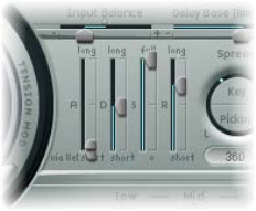
Chapter 13 Sculpture 255
•Bender Range Up/Down elds: Drag to set the upward/downward pitch bend range.
•Separate settings are available for upward and downward pitch bends—using your MIDI
keyboard’s pitch bend controller.
•When Bender Range Down is set to Linked, the Bender Range Up value is used for both (up
and down) directions.
Note: Bending the string, just like the string on a real guitar, will alter the shape of the
modeled string, rather than merely act as a simple pitch bend.
Sculpture amplitude envelope parameters
The parameters discussed in this section apply on a per-voice basis. This is a straightforward
ADSR envelope that scales the pickup signals before passing them on to the Waveshaper and
lter.
The positioning of the amplitude envelope at this point in the signal path produces more
natural-sounding results because you can control signal levels before sending them to the
Waveshaper (if used). The Waveshaper can have a signicant impact on the spectral content of
the sound, which can lead to synthetic-sounding results.
Amplitude envelope parameters
•A(ttack)—Soft and Hard slider(s): The lower slider (Soft) sets the attack time for a note
played at maximum velocity. The top slider (Hard) sets the attack time for a note played at
minimum velocity. You can adjust both slider halves simultaneously by dragging in the space
between them.
Important: The attack time parameters of the amplitude envelope have a major impact on
the way a single note is retriggered. When both Attack Soft and Hard are set to a value of 0,
the vibrating string is retriggered. If either of these parameters is set to a value above 0, a new
note is triggered. Sonically, the retriggering of a vibrating string results in dierent harmonics
being heard during the attack phase.
•D(ecay) slider: Drag to set the time it takes for the signal to fall to the sustain level, following
the initial strike/attack time.
•S(ustain) slider: Drag to set the sustain level. The sustain level is held until the key is released.
•R(elease) slider: Drag to set the time it takes for the signal to fall from the sustain level to a level
of 0. Short Release values help to reduce CPU load, because the voice is no longer processed
after the release phase has completed.
Note: Even with long decay and release times, the sound may decay quickly. This can be caused
by high Inner or Media Loss values in the string material section or by objects (2 or 3) that are
used to damp the string.

Chapter 13 Sculpture 256
Use Sculpture’s Waveshaper
The Waveshaper imposes a nonlinear shaping curve on each voice of the signal coming from the
pickups and amplitude envelope. This reshaped signal is then passed on to the lter. This process
is quite similar to the waveshaping of oscillators in synthesizers such as Korg’s O1/W.
Waveshaper parameters
•Waveshaper On/O button: Turns the Waveshaper on or o.
•Type pop-up menu: Select one of four waveshaping curves. See the table.
•Input Scale knob (morphable): Rotate to cut or boost the input signal, prior to processing
by the Waveshaper. Positive values result in a richer harmonic spectrum. Any level increase
introduced by this parameter is automatically compensated for by the Waveshaper.
Note: Given its impact on the harmonic spectrum, Input Scale should be viewed and used as
a timbral control, rather than a level control. Also note that extreme Input Scale values can
introduce processing noise at the Waveshaper output.
•Variation knob (morphable): Rotate to change. Impact is dependent on the selected
Waveshaper curve. See the table.
Type Variation controls Value of 0.0 Negative values Positive values
VariDrive Wet/dry ratio Provides shaped
signal only.
Reduces shaped
signal and adds dry
signal.
Raises shaped
signal and adds
phase-inverted
dry signal, making
sound sharper.
•SoftSat
•Tube Dist.
•Scream
Bias—alters the
symmetry of the
shaping curve.
Results in
symmetrical
shaping.
Alters symmetry. Alters symmetry.
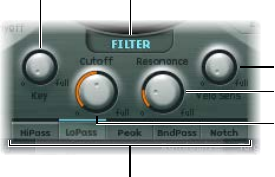
Chapter 13 Sculpture 257
Sculpture lter parameters
The parameters discussed in this section apply on a per-voice basis. A number of parameter
names are followed by (morphable), which indicates that the parameters can be morphed
between as many as ve morph points. For more information, see Sculpture morph overview on
page 280.
The lter parameters provide further timbral/spectral control over your sound. They will be
familiar to you if you have any experience with synthesizers. If you’re new to the concepts behind
synthesizer lters, see Filters overview on page 483.
Key knob
Filter Type buttons
Filter on/off button
Velo Sens knob
Resonance knob
Cutoff knob
Filter parameters
•Filter On/O button: Turns the lter section on or o.
•Filter type buttons: Click to choose the lter mode.
•HiPass: Allows frequencies above the cuto frequency to pass. Because frequencies below
the cuto frequency are suppressed, it’s also known as a low cut lter. The slope of the lter is
12 dB/octave.
•LoPass: Allows frequencies that fall below the cuto frequency to pass. Because frequencies
above the cuto frequency are suppressed, it’s also known as a high cut lter. The slope of
the lter is 12 dB/octave.
•Peak: Allows the center of a frequency band to be specied with the Cuto knob. Bandwidth
and gain are controlled with the Resonance knob. Frequencies outside the band are left at
their current level. Peak lters are generally used to enhance a frequency range.
•BandPass: The frequency band surrounding the center frequency is allowed to pass.
Resonance controls the width of this band. All other frequencies are cut. The bandpass lter
is a two-pole lter with a slope of 6 dB/octave on each side of the band.
•Notch: The frequency band surrounding the center frequency is cut. Resonance controls the
width of this band. All other frequencies are allowed to pass. Notch lters are generally used
to suppress noise or a particular frequency.
•Cuto knob (morphable): Rotate to set the cuto or center frequency, depending on the chosen
lter type. In a lowpass lter, all frequency portions above the cuto frequency are suppressed,
or cut o, hence the name. The cuto frequency controls the brilliance of the signal. The higher
the cuto frequency is set, the higher the frequencies of signals that are allowed to pass
through the lowpass lter.
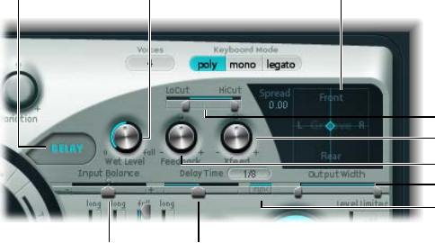
Chapter 13 Sculpture 258
•Resonance knob (morphable): Rotate to set the lter resonance value.
•In highpass and lowpass modes, Resonance emphasizes the portions of the signal that
surround the center frequency.
•In Peak, Bandpass, and Notch modes, Resonance controls the width of the band that
surrounds the center frequency.
•Key (tracking) knob: Rotate to determine how cuto frequency responds to key position. The
farther up or down the keyboard you play, the more bright or mellow the sound becomes.
Technically speaking, the cuto frequency is modulated by the keyboard position. A value of
0.0 disables key tracking. A value of 1.0 makes the cuto frequency follow the fundamental of
the note across the entire keyboard range. Play an octave higher and the cuto frequency also
changes by an octave.
•Velo Sens knob: Rotate to determine how cuto frequency responds to incoming note
velocities. The harder you strike the keyboard, the higher the cuto frequency—and, generally,
the brightness of the sound—becomes. A value of 0.0 disables velocity sensitivity. A value of
1.0 results in maximum velocity sensitivity.
Sculpture delay eect parameters
Sculpture delay eect overview
This is a (project) tempo-syncable stereo delay. It can also run freely (unsynchronized). The Delay
section features all the general delay parameters you’d expect from a delay plus the Groove
(delay timing) Pad.
LoCut/HiCut sliders
Groove pad
Output Width slider
Delay Time slider
Sync button
Feedback knob
Delay on/off button Wet Level knob
Xfeed knob
Input Balance
slider
Delay eect parameters
•Delay On/O button: Turns the Delay eect on or o.
•Wet Level knob: Rotate to set the Delay output level.
•Feedback knob: Rotate to set the amount of delay signal that is routed back from the
delay unit output channels to the delay unit input channels. Negative values result in
phase-inverted feedback.
•Xfeed (Crossfeed) knob: Rotate to set the amount of delay signal that is fed from the delay unit’s
left output channel to the right input channel and vice versa. Negative values result in phase-
inverted feedback of the crossfed signal.
•LoCut slider: Determines the cuto frequency of the highpass lter at the delay line output/
feedback loop.
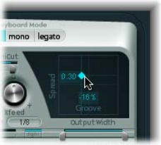
Chapter 13 Sculpture 259
•HiCut slider: Determines the cuto frequency of the lowpass lter at the delay line output/
feedback loop.
•Groove Pad: Use to graphically adjust delay times in stereo instances. See Sculpture’s Groove
Pad (stereo) on page 259.
•Input Balance slider: Drag to move the stereo center of the Delay input to the left or right,
without the loss of any signal components. This makes it ideal for ping-pong delays.
•Delay Time slider and eld: Drag to set the delay time. This can be in either musical note
values—1/4, 1/4t (1/4 triplet), and so on (see “Sync button” below)—or in milliseconds.
•Sync button: Set either tempo-synced or free-running delay modes.
•Output Width slider: Drag to change the stereo base of the wet signal. A value of 0.0 results in
mono output. A value of 1.0 results in full stereo output—the left delay line output channel is
panned hard left, and the right delay line output channel is panned hard right, but the stereo
center is unaected.
Note: This parameter is aimed primarily at achieving pure delay grooves in both channels,
without hard left/right ping-pong panning.
Sculpture’s Groove Pad (stereo)
When used in a stereo instance of Sculpture, the Spread and Groove parameters are displayed in
the two-dimensional Groove Pad.
Drag the diamond in the center of the crosshair to adjust the values. You can also independently
adjust the Spread and Groove parameter values by dragging the lines that intersect
the diamond.
You can also Control-click the Groove Pad to open a shortcut menu that contains Copy, Paste,
and Clear commands. These can be used to copy and paste delay settings between multiple
Sculpture instances or between consecutively loaded settings. The Clear command resets the
current delay settings.
Groove Pad parameters
•Spread: Adjust for wide stereo delay eects. Values on the y-axis (above the default, centered
position) increase the delay time of the right delay line or decrease the delay time of the left
delay line—in eect, smearing the delay times of the left and right channels. Negative values
invert this eect.
•Groove: Distributes delay taps to the left/right channels, rather than smearing them, like the
Spread parameter. Values on the x-axis reduce the delay time of one delay line by a given
percentage, while keeping the other delay line constant. Keep an eye on the small help tag
while adjusting.
For example, a value of +50% reduces the right delay time by half. If a value of 1/4 was used as
the Delay Time, the right delay would equal 1/8 of a note and the left delay would remain at
1/4 of a note. Needless to say, this parameter is perfect for the creation of interesting rhythmic
delays—in stereo.

Chapter 13 Sculpture 260
Sculpture Body EQ parameters
Sculpture Body EQ overview
The Body EQ can work as a simple EQ, as a complex spectral shaper, or as a body response
simulator. In eect, the Body EQ can emulate the resonant characteristics of a wooden or metallic
body—such as that of a guitar, violin, or ute.
The various models are derived from impulse response recordings of actual instrument bodies.
These recordings have been separated into their general formant structure and ne structure,
enabling you to alter these properties separately.
The Body EQ aects the summed signal of all voices, rather than each voice independently.
On/off button
Model menu
Body EQ global parameters
•Body EQ On/O button: Turns the spectral shaping (Body EQ) section on or o.
•Model pop-up menu: Choose from various emulations of acoustic instrument bodies or the
Basic EQ model. Your selection is reected in the graphical display to the right.
Note: When Basic EQ or another Body EQ model is chosen, the three knobs and slider
parameter names and behaviors change. See Use Sculpture’s Basic EQ model on page 261, and
Use Sculpture’s Body EQ models on page 262.
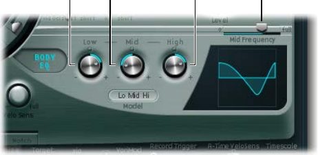
Chapter 13 Sculpture 261
Use Sculpture’s Basic EQ model
The Basic EQ parameters dier from other EQ models.
Low knob High knobMid knob Mid Frequency slider
Basic EQ parameters
•Low knob: Rotate to set the gain of a low shelving lter.
•Mid knob: Rotate to set the gain of a peak lter (sweepable—see “Mid Frequency slider”
below).
•High knob: Rotate to set the gain of a high shelving lter.
•Mid Frequency slider: Drag to sweep the center frequency of the mid band between 100 Hz and
10 kHz.
Adjust the Basic EQ (Lo Mid Hi model) graphically
mTo control the Low parameter: Drag the left third of the graphic vertically.
mTo control the Mid parameter: Drag the center third of the graphic vertically.
mTo control the Mid Frequency parameter: Drag the center third of the graphic horizontally.
mTo control the Hi parameter: Drag the right third of the graphic vertically.
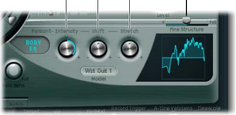
Chapter 13 Sculpture 262
Use Sculpture’s Body EQ models
All other Body EQ models provide the following parameters:
Shift Fine Structure slider
Intensity Stretch
Body EQ parameters
•Formant–Intensity knob: Rotate to scale the intensity of the model’s formants. Any formants
(harmonics) in the model become louder or are inverted, depending on how this parameter is
used. A value of 0.0 results in a at response. A value of 1.0 results in strong formants. Negative
values invert the formants.
•Formant–Shift knob: Rotate to shift the formants logarithmically. A value of −0.3, for example,
shifts all formants one octave downward, and a value of +0.3 shifts the formants up one
octave. A value of +1.0 shifts up by a factor of 10—from 500 Hz to 5000 Hz, for example.
•Formant–Stretch knob: Rotate to stretch the formant frequencies, relative to each other.
This parameter alters the width of all bands being processed by the Body EQ, extending
or narrowing the frequency range. Low Formant Stretch values move the formants closer
together (centered around 1 kHz), whereas high values move the formants farther apart from
each other. The control range is expressed as a ratio of the overall bandwidth.
Note: When combined, Formant Stretch and Formant Shift alter the formant structure of the
sound and can result in some interesting timbral changes.
•Fine Structure slider: Drag to enhance the spectral (harmonic) structure, making the overall
harmonic makeup of the sound more precise. This results in a more detailed sound that is
harmonically richer and—depending on the model selected—more guitar-like or violin-like,
for example. In other words, the resonant cavities of the instrument become more resonant—
somewhat like the increased depth of tone provided by a larger-bodied guitar. A value of
0.0 denotes no ne structure. A value of 1.0 results in enhanced/full ne structure of the
selected model.
Note: Heavy use of Fine Structure may be quite CPU intensive. Also note that Fine Structure
may not actually result in much dierence in your sound. It is highly dependent on several
string, Waveshaper, and Body EQ model parameter settings. As always, use your ears!
Adjust Body EQ models graphically
mTo control the Formant Intensity parameter: Drag the graphic vertically.
mTo control the Formant Shift parameter: Drag the graphic horizontally.

Chapter 13 Sculpture 263
Sculpture output parameters
The Level Limiter is useful for softening some of the more aggressive aspects—such as snarling
or roaring sonic artifacts—that you may encounter when using Sculpture.
Output parameters
•Level knob: Rotate to set the overall output level of Sculpture.
•Level Limiter mode buttons:
•O: Turns the Level Limiter o.
•Mono: Turns on a monophonic limiter that processes the summed signal of all voices.
•Poly: Turns on a polyphonic limiter that processes each voice independently.
•Both: Turns on a combination of both limiter types.
Sculpture modulation controls
Sculpture modulation overview
Sculpture is equipped with a huge number of modulation sources and targets, making it an
instrument that can generate extraordinary sounds that constantly evolve, sound like audio
loops, or are just plain expressive to play.
Some of the modulation sources provided are like those found on traditional synthesizer designs.
These include:
•Two freely assignable LFOs, with (project) tempo-syncable rates.
•A third LFO that is dedicated to vibrato—pitch modulation.
•Two envelopes that can be used as standard envelopes, but which can also be used
quite dierently.

Chapter 13 Sculpture 264
Sculpture also includes a number of specially designed modulation sources that are less
conventional. These include:
•Two jitter generators with adjustable bandwidth—used to create random variations.
•Two Randomizers that change values only at note start/on—perfect for emulating the lip,
breath, and tongue eects of brass instrument players, for example.
•Two recordable envelopes that can be used as MIDI controlled modulators—with the
ability to polyphonically play back on a per-voice basis, and modify incoming MIDI
controller movements.
Sculpture does not provide a centralized modulation router. All modulation routings—choosing
a modulation target and/or via source—are made within each modulation source pane.
Open a modulation source pane
mClick the button of the modulation source you want to use. When a modulation source is active,
the corresponding button label is highlighted.
Sculpture LFOs
Sculpture LFO overview
Sculpture oers two multiwaveform LFOs. Both can be used either polyphonically,
monophonically, or somewhere in-between.
If used monophonically, the modulation is identical for all voices. Imagine a scenario where
a chord is played on the keyboard. If LFO 2 is used to modulate pitch, for example, the
pitch of all voices in the played chord will rise and fall synchronously. This is known as a
phase-locked modulation.
In the same scenario, if LFO 2 is used polyphonically—to modulate multiple voices—they will not
be phase-locked.
If a random (in-between) value is used, some notes will be modulated synchronously, and others
won’t.
Furthermore, both LFOs are key-synced: Each time you play a key, the LFO modulation of this
voice is started from 0.
To understand the non-phase-locked characteristic more easily, imagine a situation where a
chord is played on the keyboard. If LFO 2 is used to modulate pitch, for example, the pitch of one
voice might rise, the pitch of another voice might fall, and the pitch of a third voice might reach
its minimum value. As you can see from this example, the modulation is independent for each
voice, or note.
The key sync feature ensures that the LFO waveform cycle always starts from 0, which results in
consistent modulation of each voice. If the LFO waveform cycles were not synchronized in this
way, individual note modulations would be uneven.
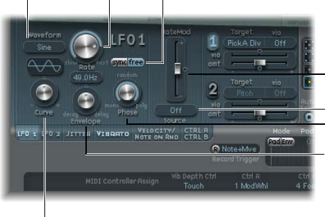
Chapter 13 Sculpture 265
Both LFOs can also be faded in or out automatically, courtesy of built-in envelope generators.
Envelope knob
Waveform menu Rate knob Sync/Free buttons
Curve knob
Rate Mod slider
Phase knob
Source menu
LFO parameters
•Waveform pop-up menu: Choose the waveform used for LFO modulation. See Sculpture LFO
waveforms on page 266.
•Waveform display: Shows the results of changes to the Waveform pop-up menu and Curve
knob parameter settings.
•Curve knob: Rotate to change the shape of modulation waveforms. A pure waveform of the
chosen type is active at a value of 0.0. The +1 and −1 positions deform the wave. For example,
with a sine wave chosen as the LFO waveform type:
•Curve value of 0.0: Wave is sine-shaped.
•Curve values above 0.0: Wave is smoothly changed into a nearly rectangular wave.
•Curve values below 0.0: The slope at the zero crossing is reduced, resulting in shorter soft
pulses to +1 and −1.
•Rate knob: Rotate to set the rate of LFO modulation. This is either a freely denable Hz value
(when the Free button is active), or a rhythmic value (when the Sync button is active). When
synchronized with the project tempo, available rates range from 1/64 notes to a periodic
duration of 32 bars. Triplet and punctuated values are also accessible.
•Sync/Free buttons: Click to choose either synchronized or free-running LFO rates. These buttons
interact with the Rate knob. The synchronized value is derived from the host application
tempo and meter.
•Envelope knob: Rotate to set the time it takes for the LFO modulation to fade in or fade out.
See Modulate Sculpture LFOs on page 267.
•Phase knob: Rotate to choose between monophonic or polyphonic LFO modulations. These
can have similar phases, completely random phase relationships, key-synced phases, or
anything in-between.
Tip: If you move the Phase knob slightly away from the mono position, you get nonlocked
modulations for all voices running at similar, but not identical, phases. This is ideal for
string-section vibratos.
•RateMod Source pop-up menu: Choose a modulation source for the LFO Rate parameter.
•RateMod Amount slider: Move to set the intensity—the amount—of LFO rate modulation.

Chapter 13 Sculpture 266
Sculpture LFO waveforms
The LFO Waveform pop-up menus set dierent waveforms for the LFOs. The table below outlines
how these can aect your modulations.
Waveform Comments
Sine Ideal for constant, even, modulations.
Triangle Well-suited for vibrato eects.
Sawtooth Well-suited for helicopter and space gun sounds.
Intense modulations of the oscillator frequencies with
a negative (inverse) sawtooth wave lead to “bubbling”
sounds. Intense sawtooth modulations of lowpass
lter cuto and resonance create rhythmic eects. The
waveform can also be inverted, resulting in a dierent
start point for the modulation cycle.
Rectangle Use of the rectangular waves periodically switches
the LFO between two values. The Rectangle Unipolar
wave switches between a positive value and 0. The
Rectangle Bipolar wave switches between a positive
and a negative value set to the same amount above
and below 0.
An interesting eect can be achieved by modulating
pitch with a suitable modulation intensity that leads
to an interval of a fth. Choose the upper rectangular
wave to do this.
Sample & Hold The two Sample & Hold (S & H) waveform settings
of the LFOs output random values. A random value
is selected at regular intervals, as dened by the LFO
rate. The S & H waveform steps between randomized
values (rapid switches between values). The S & H Lag
setting smooths the random waveform, resulting in
uid changes to values.
The term Sample & Hold refers to the procedure of
taking samples from a noise signal at regular intervals.
The values of these samples are then held until the
next sample is taken.
Tip: A random modulation of pitch leads to an eect
commonly referred to as a random pitch pattern
generator or sample and hold. Try using very high
notes, at very high rates and high intensities—you’ll
recognize this well-known eect from hundreds of
science ction movies.
Filtered Noise Can be used for chaotic modulations, but it is
principally of use in conjunction with the LFO
envelope function, where you would introduce a brief
modulation at some point in the note phase—for
example, to introduce breath in a brass emulation, or
to control an organ key click or piano hammer noise.
The random nature of the noise waveform means that
such modulations would vary slightly each time.
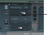
Chapter 13 Sculpture 267
Modulate Sculpture LFOs
Two modulation targets can be assigned per LFO. An optional via modulation can also
be assigned.
The LFOs also feature a simple envelope generator, which is used to control the time it takes for
the LFO modulation to fade in or fade out. At its center position, which is accessed by clicking
the middle mark, the modulation intensity is static—in other words, no fade-in or fade-out
will occur.
Click the 1 or 2 buttons
to activate each source.
LFO target and source parameters
•LFO Modulation On/O buttons (1 and 2): Turn each LFO on or o, independently.
•Modulation Target pop-up menus: Choose the modulation targets.
•Via Source pop-up menus: Choose (or disable) the via sources that control the modulation
scaling for each LFO.
•Amt sliders: Move to set the modulation amount (when the incoming via signal is 0)— for
example, when the modulation wheel is at its minimum position.
In cases where the via source is set to o, only one amount slider is visible (the via amount
slider is hidden). In cases where any via source other than o is selected, there are two sliders.
•Via (Amount) sliders: Move to set the via modulation amount (when the incoming via signal is
at its maximum)—for example, when the Modulation wheel is at the maximum position.
Set the LFO modulation fade time
mTo fade in the modulation: Rotate the Envelope knob to a positive value.
The higher the value, the longer is the delay time.
mTo fade out the modulation, rotate the Envelope knob to a negative value.
The farther to the left the knob is positioned, the shorter is the fade-out time.
Set up a delayed vibrato
LFO envelopes are most often used for delayed vibrato—many instrumentalists and singers
intonate longer notes this way.
1 Set the LFO Envelope knob toward the right (Delay) and choose pitch as the target.
2 Set a slight modulation intensity.
3 Select an LFO Rate of 5 Hz.
4 Choose the triangular wave as the LFO waveform.
Tip: Chaotic and fast modulations of pitch by an LFO source—with a delayed Sample&Hold
waveform, a high Rate, and short fade-out—are ideal for emulating the attack phase of
brass instruments.
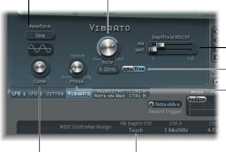
Chapter 13 Sculpture 268
Sculpture Vibrato parameters
One LFO is hard-wired to pitch, for vibrato eects, periodic pitch modulations. You can adjust
the strength of the vibrato eect by the MIDI controller you choose from the Vib Depth Ctrl
pop-up menu, which is in the MIDI Controller Assignment section. See Dene Sculpture MIDI
controllers on page 289.
Phase knob
Waveform menu Rate knob
Curve knob
DepthviaVibCtrl sliders
Sync/Free buttons
Vib Depth Ctrl
Vibrato parameters
•Waveform pop-up menu: Choose the waveform used for vibrato—sine, triangle, sawtooth, and
so on. See Sculpture LFO waveforms on page 266.
Note: There are two special rectangular waves, Rect01 and Rect1—the former switching
between values of 0.0 and 1.0 (unipolar), and the latter switching between values of −1.0 and
+1.0 (bipolar, like the other waveforms).
•Curve knob: Rotate to change the shape of modulation waveforms. Such variations can result in
subtle or drastic changes to your modulation waveforms.
Note: The waveform displayed between the Curve knob and the Waveform menu shows the
results of these two parameter settings.
•Phase knob: Rotate to choose between strictly monophonic or polyphonic vibrato with variable
phase relationships. These can be similar phases, completely random phase relationships, key-
synced phases—or any value in between. For more details, see Sculpture LFO overview on
page 264.
•Rate knob: Rotate to set the rate of vibrato, which can be either synced to the current project
tempo or set independently in Hz (Hertz) values.
•Sync/Free buttons: Select either a synchronized or free-running vibrato rate. These buttons
interact with the Rate knob. The synchronized value is derived from the host application
tempo and meter.
•DepthviaVibCtrl sliders: Drag to dene the impact of the controller assigned to Vib Depth Ctrl
(see Dene Sculpture MIDI controllers on page 289).
•Via slider: Drag to determine the modulation intensity of the controller assigned to Vib
Depth Ctrl.
•Amt slider: Drag to determine the maximum modulation amount.
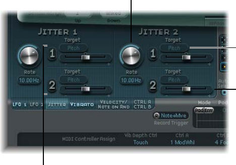
Chapter 13 Sculpture 269
Sculpture Jitter generators
Many sounds can benet from small, random modulations to parameters. These can emulate the
subtle variations that occur when particular instruments are played.
The two jitter generators are special LFO sources that are designed to produce continuous,
random variations—such as those of smooth bow position changes. The jitter generators are
equivalent to general purpose LFOs set to a noise waveform.
Note: Jitter modulation of pickup positions as the target produces great chorus-like eects.
Rate knob
Target menu
Amount slider
Click the 1 or 2 buttons
to activate each jitter
source.
Jitter generator parameters
•Rate knobs: Rotate to set the speed of the modulation (jitter) signal for each jitter generator.
•Jitter On/O buttons (1 and 2): Turn each jitter generator on or o, independently.
•Target 1 and 2 pop-up menus: Choose modulation targets 1 and 2, for each jitter generator.
•Amount 1 and 2 sliders: Drag to determine the amount of modulation for each jitter source.
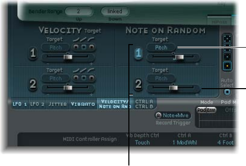
Chapter 13 Sculpture 270
Sculpture note-on random modulators
The two note-on random sources are intended for random variations between dierent notes
or voices. Values are randomly generated for each note and remain constant until the voice is
released. Such randomizations are useful for adding interest or thickening the sound when you
play polyphonically. Note-on random is also useful for emulating the periodic uctuations that a
musician introduces when playing an instrument—even when repeating the same note.
Target menu
Amount slider
Click the 1 or 2 buttons
to activate each note on
random source.
Note-on Random parameters
•On/O buttons (1 and 2): Turn note-on random modulation on or o.
•Target pop-up menus: Choose the modulation target—what parameter is randomly modulated
when a note is played.
•Amount sliders: Move to set the modulation amount—the strength of the modulation.
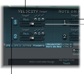
Chapter 13 Sculpture 271
Sculpture velocity modulators
The excite objects and the lter have dedicated velocity sensitivity controls. Many other
modulation routings also allow you to select velocity as a via source.
In some cases, however, it may be useful to directly control other synthesis core parameters by
velocity. This can be done in this section—where two independent target/amount/velocity curve
slots are available.
Amount slider
Curve buttons
Target menu
Click the 1 or 2 buttons
to activate each velocity
source.
Velocity modulator parameters
•On/O buttons (1 and 2): Turn velocity modulation on or o.
•Target pop-up menus: Choose the target parameter that you want to modulate with velocity.
•Amount sliders: Move to set the amount, or strength, of modulation.
•Curve buttons: Choose from concave, linear, and convex velocity curves.
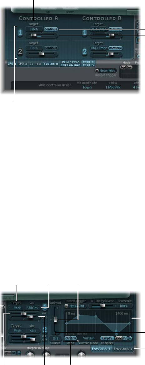
Chapter 13 Sculpture 272
Use Controller A and B in Sculpture
These parameters dene two discrete modulation targets. The modulation intensity, or strength,
is assigned to Controller A, Controller B, or both.
Amount slider
Continue button
Target menu
Click the 1 or 2 buttons
to activate each
controller source.
Controller A and B parameters
•On/O buttons (1 and 2): Turn the controller A and B modulation sources on or o.
•Target pop-up menus: Choose the target parameter that you want to modulate with the
specied controller. Each target features a two-state button (the label changes in each state).
•Continue/Note On buttons: Select either continuous modulation, or a modulation value that is
updated only when a note-on message is received.
•Amount sliders (1 and 2): Move to set the amount, or strength, of modulation.
Sculpture envelope parameters
Sculpture envelope overview
Among Sculpture’s control sources are two envelopes. In traditional synthesizer designs,
envelopes are used to control amplitude and lter levels over time. By comparison, Sculpture’s
envelopes are somewhat special in that they can be used as:
•Traditional four-segment envelopes
•MIDI controller modulations
•A combination of both—as MIDI controller movement recorders with ADSR-like macro
parameters, for polyphonic playback
Target menu VariMod slider
Mode buttons
Click here to choose
Envelope 1 or 2.
Envelope display
Via menu
VariMod Source menu
Via (amount) slider Amt slider
Chapter 13 Sculpture 273
Control envelope parameters
•Envelope 1 and 2 buttons: Choose control envelope 1 or 2, and access the parameters of each.
•On/O buttons (1 and 2): Turn the control envelope 1 and 2 modulation sources on or o.
•Target pop-up menus: Choose modulation targets 1 and 2. Two targets can be assigned per
envelope, with an optional via modulation. Targets include string, object, pickup, Waveshaper,
and lter parameters.
•Via (source) pop-up menus: Choose the modulation source used to scale the amount of
envelope modulation.
•Amt and Via (Amount) sliders: Set the modulation amount. In cases where any via source other
than “o” is selected, both sliders are available for use.
•Amt slider: Move to set the modulation amount when the incoming via signal is 0—for
example, a modulation wheel at its minimum position.
•Via (amount) slider: Move to set the modulation amount when the incoming via signal is at
full level—for example, a modulation wheel at its maximum position.
•VariMod Source pop-up menu: Choose a modulation source. (VariMod is available only for
recorded envelopes.)
•VariMod slider: Move to set the amount of envelope variation.
•Mode buttons (Ctrl and Env): Select either controller (run mode) or standard envelope behavior.
If both are activated, the controller value is added to the envelope output, resulting in a
modulation oset.
Note: When the envelopes are used as polyphonic modulation recorders and playback units,
each voice is handled independently, with a separate envelope being triggered as each note
is played.
•Envelope display: Shows the envelope curve, and enables you to record and edit envelopes. See
Use Sculpture’s envelope display on page 275 and Sculpture active envelope parameters on
page 274.

Chapter 13 Sculpture 274
Sculpture active envelope parameters
The following parameters are active only if the envelope is engaged (Mode buttons set to either
Env or Ctrl+Env).
Envelope parameters
•A-Time Velosens slider: Move to set velocity sensitivity for the attack phase of the envelope.
Positive values reduce the attack time at lower velocities. Negative values reduce the attack
time at higher velocities.
•Timescale eld: Drag to scale the duration of the entire envelope between 10% (ten times
faster) and 1000% (ten times slower). This also aects the appearance of the envelope curve
displayed as it is shortened (sped up) or lengthened (slowed down).
•Sustain Mode pop-up menu: Choose the behavior of the envelope while a note is held. Choices
are Sustain mode (default), Finish mode, and three loop modes—Loop Forward, Loop
Backward, and Loop Alternate. See Loop Sculpture envelopes on page 277.
•Sync and ms buttons: Select either a tempo-synced envelope with note value options, such as
1/8th or 1/4, or a free-running envelope (with segment times displayed in milliseconds).
Note: Switching between values forces a recalculation of times to the nearest note value or ms
time, respectively, based on the current project tempo.
•Compare button: Toggles between the original recording and the edited version.
Note: This is available as an option only if an envelope curve has actually been recorded
and edited.
•VariMod-Source and Amount: Controls the strength of envelope variation with a user-dened
modulation source (available only for recorded envelopes).
•Source options include O, Velocity Concave, Velocity, Velocity Convex, KeyScale, Ctrl A, and
Ctrl B.
•Variation in the envelopes means the deviation of a recorded envelope path from straight
interconnecting lines between the points. After you record an envelope, you can reduce
or exaggerate the amplitude-jitter (variation) of the recording by Command-dragging the
curves between points down (to reduce) or up (to exaggerate).
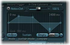
Chapter 13 Sculpture 275
Use Sculpture’s envelope display
The envelope curve is shown in the display to the lower right of the Sculpture interface. The
envelope display is active only if the envelope is engaged (Mode buttons are set to either Env or
Ctrl+Env).
•The overall time/length of the envelope is indicated by the numerical entry at the top right of
the window (2400 ms in the gure).
•The maximum time/length of the envelope is 48 bars/40 seconds.
•The lines on the background grid are placed 100 milliseconds apart.
•The background lines are placed 1000 ms apart when very long envelope times are displayed.
In sync mode, this is displayed as 1 quarter.
•The envelope is zoomed automatically after you release the mouse button. This displays the
entire envelope at the highest possible resolution. You can disable or enable this feature by
clicking the Autozoom button—the small magnifying glass.
•Autozoom is automatically disabled when you perform a manual zoom—by clicking the
envelope display background, and dragging horizontally. As a reference, the current display
width is displayed in the numerical entry at the top right of the display. You can re-engage
automatic zooming by clicking the Autozoom button.
•If you click the handles (nodes) or lines between the nodes in the envelope display, the current
envelope segment becomes highlighted. A small help tag also indicates the millisecond value
of the current segment.
Copy, paste, or clear Sculpture envelopes with the shortcut menu
You can copy and paste envelopes between Envelopes 1 and 2, between settings, or between
multiple open Sculpture instances. The Clear command deletes the selected envelope.
mControl-click the envelope buttons or the envelope display background, then choose Copy, Paste,
or Clear from the shortcut menu.
Chapter 13 Sculpture 276
Use Sculpture envelope nodes
When an envelope is rst opened, a default envelope curve is automatically created for each
envelope. Click the (Mode) Env button to view it.
A few handles (nodes) are placed—from left to right—along a straight line within the envelope.
These are indicators of the following parameters.
•Node 1: Start level—cannot be repositioned
•Node 2: Attack time position/level
•Node 3: Loop time position/level
•Node 4: Sustain time position/level
•Node 5: End time position/level
As you move the pointer along the line, or place it over the nodes, the current envelope segment
is highlighted.
You can create your own envelopes manually by manipulating the nodes and lines, or you can
record an envelope, as discussed in Record Sculpture envelopes on page 278.
Adjust the time between nodes
mDrag a handle left or right.
As you drag, the overall length of the envelope changes—with all following nodes being moved.
When you release the mouse button, the envelope display automatically zooms to show the
entire envelope.
Note: You cannot move a node beyond the position of the preceding node. You can, however,
move nodes beyond the position of the following node—even beyond the right side of the
envelope display—eectively lengthening both the envelope segment and the overall envelope.
Set the level of each node
mDrag a handle up or down.
Change the shape of the curve between nodes
mFor simple (nonrecorded) envelopes, drag the line that connects nodes up or down.
mFor recorded envelopes, which may have a more complex curve between nodes, Control-drag
the curve.
Chapter 13 Sculpture 277
Loop Sculpture envelopes
The envelope can run in one-shot mode, like any envelope—the envelope phases run for as long
as the note is held. It can also run through each phase several times or in an innite cycle, much
like an LFO. You can achieve this through the use of loops.
You can synchronize loops to the project tempo automatically by using the sync and ms buttons.
When you are in any of the loop modes, the loop always cycles between user-dened envelope
handles that indicate the Loop start point (L icon), and the Sustain point (S icon). You can drag
these handles to any position.
•When set to Finish, the envelope runs in one-shot mode from beginning to end—even if
the note is released before all envelope phases have completed. The other loop parameters
are disabled.
•When set to Loop Forward, the envelope runs to the Sustain point, and begins to periodically
repeat the section between the Loop and Sustain points—always in a forward direction.
•When set to Loop Backward, the envelope runs to the Sustain point, and begins to periodically
repeat the section between the Sustain and Loop points—always in a backward direction.
•When set to Loop Alternate, the envelope runs to the Sustain point, then periodically
returns to the Loop point and back to the Sustain point, alternating in both a backward and
forward direction.
Note: If the Loop point lies behind the Sustain point, the loop will start after the key is released.

Chapter 13 Sculpture 278
Record Sculpture envelopes
It is important to note that you can only record the movements of the assigned MIDI controller.
MIDI controller assignments for the envelopes must be set in the MIDI Controller Assignment
section at the bottom of the Sculpture interface (see Dene Sculpture MIDI controllers on
page 289).
Envelope MIDI controller
assignments
Envelope recording parameters
•R(ecord) button: Starts or stops envelope recording. Recording can also be stopped using the
trigger mode function described below.
•Record Trigger Mode pop-up menu: Choose dierent record trigger modes to start—and stop—
recording when Record is active.
•NoteOn: Recording starts when a note is played.
•Note + Ctrl Movement: Recording starts when MIDI control change messages arrive while
a note is held (for information about assigned MIDI controllers, see Dene Sculpture
MIDI controllers.
•Note + Sustain Pedal: Recording starts when the sustain pedal is depressed while a note
is held.
Chapter 13 Sculpture 279
Record an envelope
1 Choose a Record Trigger Mode, such as Note + Ctrl.
2 Click the Record button (the “R”) to start recording.
3 Play, and hold, a key—and start moving the controllers assigned to envelope controls 1 or 2 or
both, such as the modulation wheel.
Stop an envelope recording
Do one of the following:
mClick the Record button ( the “R”) to disengage it.
mRelease all voices.
mPlay a new note after releasing all keys.
Note: When a controller movement has been recorded, R(ecord) is automatically set to o and
Mode is set to Env. This ensures that only the recorded movement is active, regardless of the stop
position of the recorded controller.
Play a recorded envelope
mPlay a key to begin polyphonic playback of the recorded envelope.
Note: The Mode parameter must be set to Env and the R(ecord) parameter must be set to o.
You can also turn on both the Env and Ctrl buttons of the Mode parameter, which enables you
to use controllers assigned to Ctrl Env1 or Ctrl Env2 to manipulate the envelope in real time,
alongside playback of the recorded envelope.
Note: When both Env and Ctrl are turned on, the controller value is added to the envelope
output, resulting in a modulation oset.
Prepare a recorded envelope for editing
mThe envelope segments and handles are set automatically after recording. Drag the vertical lines
that intersect the handles to enable editing.
Note: This will not change the shape of the envelope.
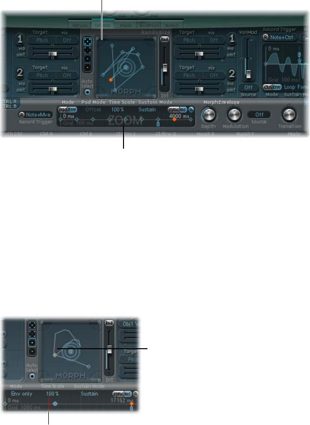
Chapter 13 Sculpture 280
Sculpture morph parameters
Sculpture morph overview
Sculpture has a number of morphable parameters, indicated in the Sculpture interface by an
orange value bar, rather than a blue or turquoise one. This makes it easy to identify, and edit, the
values of these parameters.
All morphable parameters can be independently adjusted and stored in a morph point. In
essence, the values of all morphable parameters are captured at a particular moment in time,
much like a photograph. You can smoothly change the sound—in a subtle or radical way—by
transitioning between up to ve morph points.
The Morph Pad and Morph Envelope enable you to create, and precisely control, the movements
and blending between morph points.
Morph Pad
Morph envelope
The Morph section consists of two parts:
•Morph Pad: Used to display and edit, or draw, morph point paths. There are ve morph
points—the four corners and the center—plus menu options for randomizing and copying
and pasting morph points or Morph Pad states.
•Morph Envelope: Used to display and edit morph points—either by segment (with a mouse or
trackpad), or recorded MIDI controller movements. For example, you could use a vector stick
(Morph X/Y controllers) or drag the morph ball (on the Morph Pad).
The current morph point position is indicated by the ball in the Morph Pad. This can be moved
with MIDI controllers, such as a vector stick, or with the mouse. Such movements can be
recorded and played back independently—with each voice being morphed in a dierent way.
The dot indicates the
current morph position.
The line indicates the
current morph position.
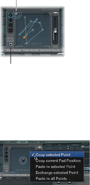
Chapter 13 Sculpture 281
During a morph, the red line in the Morph Envelope timeline shows the current time position,
and the Morph Pad displays a moving dot that indicates the current morph position.
Note: The current morph position is only shown if one note is being played.
Use Sculpture’s Morph Pad
Morph points in Sculpture’s Morph Pad
One of the ve Morph Pad points (A, B, C, D, and Center) is always selected for editing. This
selected point is indicated by two concentric circles that surround it.
Auto Select button
Active morph point
When you turn on Auto Select mode, the nearest morph point will be automatically selected
when you move the ball in the Morph Pad.
You can also click in the circles around A, B, C, D, or the center, to manually select a Morph
Pad point.
Sculpture Morph Pad menu commands
You can open the shortcut menu by Control-clicking the Morph Pad. The menu contains Copy,
Paste, and Exchange commands.
•Copy selected Point: Copies the current morph point into Sculpture’s Clipboard.
•Copy current Pad Position: Copies the current morph state into Sculpture’s Clipboard.
•Paste to selected Point: Pastes the Clipboard content to the selected point.
•Exchange selected Point: Swaps previously copied data with the selected point.
•Paste to all Points: Pastes the Clipboard content to all selected points.

Chapter 13 Sculpture 282
Randomize morph points in Sculpture’s Morph Pad
The randomize feature creates random variations of selected morph points. When combined
with the copy/paste function, randomizing lends itself to using the Morph Pad as an automatic
sound generator.
Use of the Morph Pad can yield interesting composite sounds—hybrids of the original and
morphed sound. You can copy this hybrid sound to a corner of the Morph Pad, or to several
corners, and randomize it by a denable amount. The morphed sound then becomes a new
timbral element that can, in turn, be moved to the corners, randomized, and so on.
In eect, you are “breeding” a sound, while maintaining some control by selecting parent
and child sounds. This approach can result in new, complex sounds—even if your sound
programming knowledge is limited.
Intensity slider
Point buttons
Randomize button
Morph point randomize parameters
•Point buttons: Click to dene the number of morph points that you want to use for
randomization. The active button indicates which points will be randomized.
The bottom button, when selected, limits randomization to the currently selected
morph point.
•Auto Select button: Turn on to automatically select the closest morph point.
•Randomize button: Click to create randomized values for all parameters of the chosen
morph points.
•Int(ensity) slider: Move to set the amount of randomization from 1% (slight deviation) to 100%
(completely random values).

Chapter 13 Sculpture 283
Randomize morph points
This example provides a general approach that you can follow for morph point randomization.
1 Select a Point button (the top, ve-point button, for example).
2 Turn on Auto Select.
3 Drag the Int(ensity) slider to a value of 25%.
4 Click the Rnd button.
Note the movement of a number of the parameters in the core synthesis engine.
5 Drag the morph ball to each corner in the Morph Pad. Do this along the edges and through the
center of the Morph Pad.
Note how this aects the morph.
6 Strike a few notes on your MIDI keyboard while dragging the ball.
Note: The morph ball is visible only when the Record Trigger button is active.
As you move the morph ball around, you’ll see ghost controls in the Pickup display and the ball
in the Material Pad move. If you look closely, you should see a number of red dots moving in the
string and object parameters, which indicate the current morph position.
Note that positions on the Morph Pad that fall in between the various morph points cause
the randomized parameters to interpolate between values. You can use the Copy and Paste
commands to make use of these in-between values.
Sculpture randomize menu commands
You can Control-click the Rnd button to open a shortcut menu containing commands that
determine which parameters are randomized with the Rnd button and Int slider.
Randomize menu commands
•All morphable parameters: Randomizes all parameters in the following groups, which can lead
to unusual sounds. This can lead to some interesting results, but it is uncontrolled, making it
unsuitable for the “sound breeding” idea discussed in Randomize morph points in Sculpture’s
Morph Pad.
•All except TensMod: Identical to All morphable parameters, but excludes the TensionMod
parameter from randomization.
•String Material/Media: Includes the Material Pad position, Stiness, Inner Loss, Media Loss,
Resolution, and Tension Modulation parameters for randomization.
•Objects&Pickups: Alters the positions of objects and pickups, plus various object parameters,
when randomization is used.
•Waveshaper&Filter: Alters the positions of all Waveshaper and lter parameters when
randomization is used.
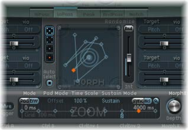
Chapter 13 Sculpture 284
Use Sculpture’s Morph Envelope
Use Sculpture’s Morph Envelope display
The Morph Envelope contains nine points and eight segments, and it has recording behavior
that is much like that of the controller envelopes.
The selected (orange)
point in the lower
panel (the Timeline)
corresponds to the
selected point in the
Morph Pad trajectory.
•The overall time/length of the Morph Envelope is indicated by the numerical entry at the top
right of the display.
•The maximum time/length of the Morph Envelope is 48 bars/40 seconds.
•The lines on the background grid are placed 100 milliseconds apart.
•If you click the handles (nodes) or lines between the nodes, the current envelope segment
becomes highlighted. A small help tag also indicates the millisecond value of the
current segment.
•As you move your pointer along the line, or place it over the nodes, the current envelope
segment is highlighted.
•You can create your own envelopes manually by manipulating the nodes and lines, or you can
record an envelope (see Record Morph Envelopes in Sculpture on page 288).
Adjust the time between nodes
mDrag a handle to the left or right. As you drag, the overall length of the Morph Envelope changes,
with all following nodes being moved.
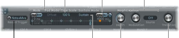
Chapter 13 Sculpture 285
Sculpture Morph Envelope parameters
The following section describes the Morph Envelope’s parameters.
Record button and
Trigger menu
Mode buttons and
Pad Mode menu Time Scale field
Sustain Mode menu
Sync/ms buttons
Depth knob Transition knob
Modulation knob and
Source menu
Morph Envelope parameters
•Record button: Click to arm the envelope for recording. See Record Morph Envelopes in
Sculpture on page 288.
•Trigger Mode pop-up menu: Choose the event type that triggers recording.
•Mode buttons: Turn on the Morph Envelope. See Sculpture’s Morph Envelope mode on
page 286.
•Pad Mode pop-up menu: Choose a Morph Envelope mode.
•Timescale eld: Drag to scale the duration of the entire envelope between 10% (ten times
faster) and 1000% (ten times slower). This also aects the appearance of the envelope curve
displayed as it is shortened (sped up) or lengthened (slowed down).
•Sustain mode pop-up menu: Choose the behavior of the Morph Envelope while a note is held.
The menu items are Sustain mode, Finish mode, three loop modes—Loop Forward, Loop
Backward, Loop Alternate—and Scan via CtrlB mode. See Sculpture Morph Envelope Sustain
and loop mode on page 286.
•Sync and ms buttons: Select either a tempo-synced envelope with note value options, such as
1/8 or 1/4, or a free-running envelope, with segment times displayed in milliseconds.
Note: Switching between values forces a recalculation of times to the nearest note value or ms
time, respectively, based on the current project tempo.
•Depth knob: Rotate to scale the amount of morph movement caused by the Morph Envelope.
The eect of the Depth parameter is visually displayed in the Morph Pad. As you increase or
decrease the value, the morph trajectory is also scaled.
•Modulation knob: Rotate to set the scaling amount for Morph Envelope movements.
•Modulation Source pop-up menu: Choose a modulation source that is used to scale Morph
Envelope movements.
•Transition knob: Rotate to control transitions between morph points. This can be the original
(possibly recorded) movement to linear, or stepped, transitions. The latter remains at one
morph state and then abruptly switches to another morph state at the following envelope
point. This parameter (and the Morph Envelope itself) can lead to interesting, evolving sounds,
or even rhythmic patches.
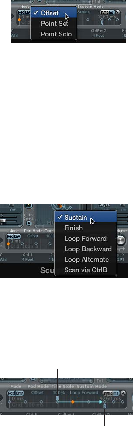
Chapter 13 Sculpture 286
Sculpture’s Morph Envelope mode
The Mode buttons activate the Morph Envelope and provide a choice of several modes:
•Both buttons o: Morph function is disabled.
•Pad only: Envelope is deactivated, and morphing is controlled by the morph ball or X/Y MIDI
controllers only.
•Env only: Envelope is running, but the morph ball and X/Y MIDI controllers are deactivated.
•Env + Pad: Envelope is running, and the position of the morph ball or X/Y MIDI controllers is
used as an oset for any envelope movements.
•Oset button: When in Env + Pad mode, choose from several menu items:
•Oset: The default mode. Behavior is the same as Env+Pad mode: Envelope is running,
and the position of the morph ball or X/Y MIDI controllers is used as an oset for any
envelope movements.
•Point Set: Envelope is running. The selected envelope point can be edited by moving the
morph ball or with a MIDI controller (MorphX and MorphY Controller Assignments).
•Point Solo: Envelope is in a kind of snapshot mode. The selected envelope point can be
edited by moving the morph ball.
Sculpture Morph Envelope Sustain and loop mode
The Sustain mode pop-up menu lets you choose one of the following modes: Sustain, Finish,
Loop Forward, Loop Backward, Loop Alternate, and Scan via CtrlB.
When you are in any of the loop modes, the loop always cycles between the loop and sustain
envelope handles—the nodes indicated by the L and S icons. The Morph Envelope can, like any
envelope, run in one-shot mode—it runs normally, for as long as the note is sustained. It can also
run several times, or in an innite cycle, much like an LFO. You can achieve the latter through the
use of loops.
Loop handle
Sustain handle
Chapter 13 Sculpture 287
The Loop and Sustain point handles can be grabbed and repositioned. Note that doing so can
potentially alter the loop (and the overall morph envelope) length. The loop modes behave as
described below:
•Finish: The envelope runs in one-shot mode from its beginning to its end—even if the note is
released before the envelope has completed. The other loop parameters are disabled.
•Loop Forward: The envelope runs to the Sustain point and begins to repeat the section
between the Loop point and Sustain point periodically—always in a forward direction.
•Loop Backward: The envelope runs to the Sustain point and begins to repeat the section
between the Sustain point and Loop start point periodically—always in a backward direction.
•Loop Alternate: The envelope runs to the Sustain point and returns to the Loop point and back
to the Sustain point periodically, alternating in both a backward and forward direction.
•Scan via CtrlB: The timeline position within the envelope is disconnected from normal, real-
time operation, enabling you to manually scan the overall time range with the MIDI controller
assigned to Ctrl B (in the MIDI Controller Assign section).
Tip: It is also possible to drag the red time position marker.
Note: If one of the three loop modes is selected, and the Loop point is positioned before the
Sustain point, the loop remains active until the key is released. Following key release, the
envelope then continues beyond the Sustain point, as usual. If the Loop point is positioned after
the Sustain point, the loop begins as soon as the key is released, and cycles continuously until
the complete voice has nished the amplitude envelope release phase.

Chapter 13 Sculpture 288
Record Morph Envelopes in Sculpture
The following section describes the steps you follow to record a Morph Envelope.
Choose a record trigger mode
mClick the Trigger mode pop-up menu to the right of the R button, then choose one of the
following trigger modes, which will start recording when R(ecord) Enable is turned on:
•NoteOn: Recording starts when a note is played.
•Note + Move Morph Point: Recording starts when MIDI control change messages (as assigned
in the Morph X and Y parameters of the MIDI Controller Assign section) arrive while a note
is held.
•Note + Sustain Pedal: Recording starts when the sustain pedal is depressed while a note is held.
Record a Morph Envelope
1 Choose a trigger mode if you don’t want to use the Morph Pad.
Skip this step if using the Morph Pad.
2 Click the R(ecord) Enable button to arm the morph envelope record function.
3 Play a note on your MIDI keyboard, and do either of the following:
•Drag the silver ball in the Morph Pad.
•Move an external controller (see Dene Sculpture MIDI controllers on page 289).
Following the recording of a controller movement, R(ecord) Enable is automatically set to o and
Mode is set to Env only. This ensures that only the recorded movement is active, regardless of the
controller’s position or further movements after you nish recording.
Note: The mode defaults to (Morph) Pad as soon as you click the R button. See Sculpture Morph
Envelope parameters on page 285.
Stop a morph envelope recording
Do one of the following:
mClick the R(ecord) Enable button (or trigger) a second time.
mRelease all keys, and allow all voices to complete their decay phase. This automatically ends
the recording.
Note: You can stop recording early, before the decay phase completes, by releasing all keys and
then pressing a single key.
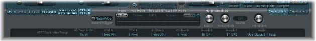
Chapter 13 Sculpture 289
Dene Sculpture MIDI controllers
The bottom strip of the Sculpture interface is used to dene MIDI controllers—for vibrato depth
control or Morph Pad movements, for example. You can use any MIDI controller shown in the
menus for these control sources.
These parameters are saved with each setting. They are updated only if the default setting that
is loaded on instantiating the plug-in is used, or if the setting was saved with a project. This
approach helps you to adapt all MIDI controllers to the keyboard without having to edit and save
each setting separately.
MIDI controller parameters
•Vib Depth Ctrl pop-up menu: Choose the MIDI controller used for vibrato depth control.
•Ctrl A and Ctrl B pop-up menus: Choose two controllers that can be used for side-chain
modulations or as via modulation sources—set in the CtrlA and CtrlB modulation
routing panes.
•CtrlEnv 1 and CtrlEnv 2 pop-up menus: Choose controller assignments for the two control
envelopes—used as a modulation signal or an oset, the latter in cases where the control
envelope is set to Ctrl only or Ctrl+Env modes. They are also used to dene the source for
recording controller movements.
•Morph X and Morph Y pop-up menus: Choose controller assignments for the x and y coordinates
of the Morph Pad. After they are assigned, the controller can be used to manually move the
morph point, program single Morph Envelope points, shift the entire Morph Envelope, and
serve as a source for recording morph movements.
•Mode menu: Choose whether you want to use the default MIDI controller assignments or
the assignments loaded from the setting. If you choose Use Default, the assignments remain
unchanged. If you choose Load From Setting, you use the assignments you saved with the
setting. (The default assignments are taken from the #default.pst setting, if it exists, which is
loaded when Sculpture is inserted into an instrument channel strip.)
Learn a MIDI controller assignment
1 Open a control pop-up menu, and choose the Learn item.
2 Move the controller on your MIDI keyboard or MIDI controller.
Note: If no suitable MIDI message is received within 20 seconds, the selected control reverts to
the previous value/assignment.
Chapter 13 Sculpture 290
Sculpture tutorials
Explore Sculpture
Explore Sculpture overview
The following sections contain information to assist you as you start to explore sound creation in
Sculpture. See Explore Sculpture’s string, Explore Sculpture’s objects, Explore Sculpture’s pickups,
and Other Sculpture processing parameters.
The creation of basic instrument sounds is discussed in Basic sound programming overview on
page 295. For a more detailed look at programming particular types of sounds, see Electric bass
programming overview on page 305 and Synthetic sound programming overview on page 323.
Given the exibility of Sculpture’s synthesis core, you can take a number of dierent approaches
to sound design.
•If you prefer to build sounds from scratch—parameter by parameter—you can.
•If you prefer to use Sculpture’s morphing capabilities to create new sounds, you can. See
Randomize morph points in Sculpture’s Morph Pad on page 282.
•If you prefer to tweak existing settings, it may be more suitable to use features that aect the
entire instrument. See Sculpture Body EQ overview, Sculpture lter parameters, Use Sculpture’s
Waveshaper, and Sculpture modulation overview.
Whatever approach you favor, you will be able to achieve new and interesting results. Experiment
and familiarize yourself with each approach. You will nd that each has its strengths and
weaknesses, and that a combination of methods may strike the best balance for your needs.
When programming a sound from scratch in Sculpture, the best approach is to work on each
component of the sound in isolation. As you’re probably new to Sculpture, you won’t be familiar
with the impact of each parameter on your end results. See String and object interactions
in Sculpture.
To start, you will need a plain vanilla setting. When you rst open Sculpture, this is exactly what
you get—a default set of neutral parameters. It is sonically uninteresting, but provides a starting
point for most examples. This setting is saved as the “#default” settings le. It is best to save a
copy of this setting before starting.
Save a default setting
mChose Save Settings As from the Settings pop-up menu, then enter the name you want—maybe
“neutral” or “vanilla”—and click Save.
This setting can be reloaded as you work through the examples.

Chapter 13 Sculpture 291
Explore Sculpture’s string
The string is the central synthesis element of Sculpture and is responsible for the basic tone. It
oers parameters that enable you to adjust its material—what it’s made of, in other words—and
to dene the environment that it’s being played in—water or air, for example.
Tip: Before starting, Control-click the string (the green horizontal line in the Pickup display), then
choose “enable string animation” from the shortcut menu. When active, the string vibrates when
you play a note, making it easier to visualize the impact of the objects and pickups.
Release button
Keyscale button
Media Loss slider
Tension Mod slider
Resolution slider
Keyscale slider
Keyscale slider
Keyscale slider
Ball
Set a basic tone
1 Click the Keyscale button at the bottom of the Material Pad ring.
2 Strike and hold or repeatedly strike middle C on your keyboard. Middle C is the default pitch of
the string.
3 While striking middle C, drag the ball around the Material Pad. Listen to the sonic changes as you
move between the Nylon, Wood, Steel, and Glass materials. Keep an eye on the string (the green
horizontal line in the Pickup display, to the left) as you’re doing so.
4 When you nd a basic tone that you like, release the mouse button.
Change the string properties
1 Now experiment with the values of each of the sliders that surround the Material Pad—the
Media Loss, Tension Mod, and Resolution parameters—while continuing to strike middle C. Note
the changes that each makes to the sound, and also to the string animation in the Pickup display.
Play a few notes above and below middle C, again keeping your eye on the string.
2 You probably noticed that moving the Media Loss, Tension Mod, and Resolution sliders also had
an eect on the green and blue Keyscale sliders inside and outside the ring. Drag each of these
Keyscale slider arrowheads to dierent positions—one by one—while you play a few notes
either side of middle C. Notice the changes that happen up or down the keyboard range.
3 When you’re done, click the Release button at the bottom of the Material Pad ring, and adjust the
blue Media Loss Release slider while you strike notes.
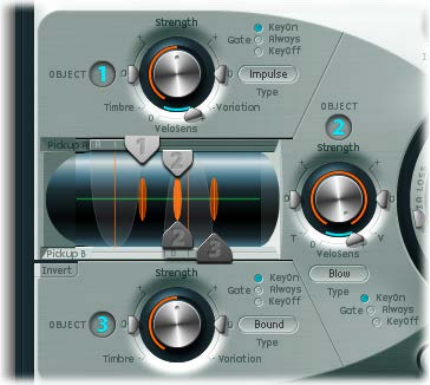
Chapter 13 Sculpture 292
Explore Sculpture’s objects
Up to three objects of dierent types are used to excite or disturb the vibration of the string.
Tip: Before starting, Control-click the string (the green horizontal line in the Pickup display), then
then choose “enable string animation” from the shortcut menu. When active, the string vibrates
when you play a note, making it easier to visualize the impact of the objects and pickups.
The three string object
dials/controls are
shown, along with the
Pickup section at the
center left.
Explore the objects in Sculpture
1 Reload the #default (or your vanilla) setting le by choosing Reset Setting from the Settings
pop-up menu.
2 Click the Object 1 button to deselect it while you are repeatedly striking a key. The sound stops
after Object 1 is deselected. The string itself doesn’t make a sound unless it is stimulated by at
least one object. Click the button again to reactivate it.
3 Choose each menu item from Object 1’s Type pop-up menu. Strike a note repeatedly while you
choose each item to hear the impact of each object type on the string. Keep an eye on the string
animation. Note that Object 1 can make use of excite types only. Object 2 can make use of either
excite or damping types. Object 3 can make use of damping types only.
4 Adjust the Strength knob by dragging vertically for large changes or horizontally for ne
adjustments. Strike a note repeatedly while doing so.
5 Drag the Timbre and VeloSens arrowheads to dierent positions while striking a key to audition
the changes that they bring.
6 The impact of the Variation parameter is dierent for each type of object. Feel free to experiment
with this as well.
7 Try out each of the Gate settings.
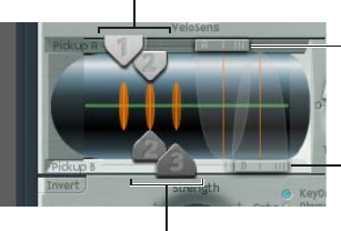
Chapter 13 Sculpture 293
String and object interactions in Sculpture
Each parameter has an impact on the overall tone of the string and—more often than not—an
impact on the string interaction of other parameters.
As you introduce or make changes to parameters, the modeled string is aected. This, in turn,
aects the interaction of each parameter with the modeled string. Therefore, parameter settings
that you already made for Object 1, for example, may need to be adjusted when Object 2 is
turned on.
Generally, such adjustments won’t need to be radical, and may involve only a small tweak to
the Strength parameters, or perhaps to the pickup positions of each object, for example. These
parameters have the greatest impact on the tone and level of the objects and should be the rst
things you look at if enabling Object 2 results in an unwanted change to the color of your sound.
You may want to ne-tune the objects further through use of the Timbre and Variation controls.
Small changes—rather than radical ones—will retain the general tonal character of the string
and Object 1, while introducing the new avor of Object 2.
Explore Sculpture’s pickups
The vibration of the string is captured by two movable pickups. The pickup section also houses
three object sliders—used to set the position of each object along the string.
Objects
Objects
Pickup A slider
Pickup B slider
Change the object positions along the string
1 Reload the #default (or your vanilla) setting le.
2 Drag the Object 1 pickup left or right while striking a key. Note that adjustment of the object
pickup position alters the tonal characteristics of the string.
3 Adjust Object 1’s Strength control to hear things better, or to adjust the tone. You can also use
Object 1’s Timbre and Variation parameters to alter the tone.
4 Feel free to adjust the positions and parameters of the other objects, if they are active.
Change the pickup positions along the string
mDrag the Pickup A and Pickup B sliders. Note that changes to the pickup positions result in quite
dierent string vibrations and tonal qualities. If you want to increase the overall volume, adjust
the Level knob on the right of Sculpture’s interface, directly opposite the Pickup section.
Chapter 13 Sculpture 294
Other Sculpture processing parameters
From the pickups, the signal is sent to the processing section, which consists of the ADSR-
equipped amplitude stage (just to the right of the circular Material Pad in the center), a
Waveshaper with selectable types of waveshaping curves (above the circular Material Pad),
and a multimode lter (below the Material Pad). All elements covered thus far exist on a
per-voice basis.
All voice signals coming from the pickups are summed, and then they are processed by an
integrated Delay eect (to the upper right of the circular Material Pad).
From there, the signal is sent to an EQ-like module (Body EQ, to the lower right of the Material
Pad), which globally simulates the spectral shape or body response of your instrument. There are
several body types to choose from.
The resulting signal is then fed to a Level/Limiter section (at the far right).
Tip: Feel free to experiment with all these parameters—using the #default (or your vanilla)
setting le each time. This will give you a general feel for each parameter and its impact on the
sounds you hear.
All other parameters on the lower portions of the Sculpture interface (Modulation, Morph,
Envelope, and Controller Assignments) are not part of the core synthesis engine, although they
can aect it.
Explore Sculpture modulation options
The modulation options can be very important for the emulation of acoustic instruments, such
as with the introduction of vibrato into a trumpet sound over time.
Many classic synthesizer sounds also rely as much on modulation as they do on the basic sound
source components—the VCO, VCF, and VCA.
Here are some quick modulation tips:
•Imagine that you want to modulate the timbre of Object 2 with the LFO, for example. To do
so, click the LFO 1 or 2 tab, click the 1 or 2 button, choose a source and target from the Source
and Target pop-up menus, then drag the “amt” and “via” sliders to the values you want.
•To control any modulation with an external controller, such as your keyboard’s modulation
wheel, open the “via” pop-up menu and choose Ctrl A (1 ModWhl) or Ctrl B (4 Foot)
respectively. By default, the Mod Wheel is set to Ctrl A.
•The Bouncing damp type available to Object 3 aects the sound in an interesting way, but it
cannot run synchronously with the project tempo. To create a similar eect to the Bouncing
Object—but in sync with the project tempo—you could use a Disturb object type, and move
it by modulating its vertical position (Timbre) with an LFO that is synchronized with the
host application.
Breath control is available when you use Sculpture, even if you don’t own a breath controller.
Use breath control without a breath controller
1 Record breath controller modulations into the recordable envelopes by using your keyboard
modulation wheel or another controller.
2 Reassign the recorded modulation routing to either, or both, the CtrlEnv 1 and
CtrlEnv 2 parameters.
3 Choose NoteOn from the Record Trigger pop-up menu.
Incoming note-on messages will trigger the CtrlEnv 1 and 2 parameters.
Chapter 13 Sculpture 295
Create basic sounds in Sculpture
Basic sound programming overview
This section covers the creation of basic types of sounds, such as organs, basses, guitars, and
so on. See Acoustic instrument programming examples, Stringed instrument programming
examples, and Classic synthesizer programming examples.
For a detailed look at programming particular types of sounds, see Electric bass programming
overview on page 305 and Synthetic sound programming overview on page 323.
The idea here is to provide you with a starting point for your own experiments and to introduce
you to dierent approaches for tone creation with Sculpture. As you become more familiar with
Sculpture and component modeling, you’ll nd that there are many ways to achieve an end
result. In other words, each component of the sound can be modeled using dierent techniques
and parameters. This exible approach allows you to create a brass sound, for example, in several
ways—using the Waveshaper as a major tonal element in one sound or the lter and Body EQ to
emulate the same sonic component in another sound.
It is helpful to have a good understanding of the physical properties of the instrument you are
trying to emulate. Although you can do some research on the Internet to obtain this type of
specialized knowledge, for most sound creation tasks you can follow the general approach set
forth below.
•How is the sound of the instrument created?
•Is it a string that is vibrating and resonating in a box (such as a guitar or violin)?
•Is it a column of air that is vibrating in a tube (a ute or trumpet)?
•Is it a solid object that is struck, causing vibration (a woodblock)?
•Is it a hollow object that is struck, causing vibration or resonance (a drum or bell)?
•What is the instrument made of?
When you answer this question, don’t just consider the body of the instrument. Take into
account the string material—nylon or steel on a guitar, or perhaps the thickness and material
of the reed in a clarinet or oboe, or a mute in a trumpet.
•Is the instrument polyphonic or monophonic?
This is a signicant factor and relates to the next question about how the instrument is played.
Some dierences between monophonic and polyphonic instruments are obvious, such as the
inability to play chords on a ute. A more subtle dierence involves the way a modeled string
will interact with any currently active string. This, of course, can’t happen in a ute, which is
strictly a one-note instrument.
•How is the instrument played?
Is it bowed, blown, struck, or plucked?
•Are there other elements that form part of the instrument sound?
•Changes in lip pressure and mouth position with brass and wind instruments
•Breath or mechanical noises
•Momentary pitch changes—for example, when ngers are pressed into a fretboard, or when
a string is plucked
•Momentary tonal or level changes—such as when brass players are running out of breath,
or uttering the valves
After you mentally, or physically, construct a list of properties, try to emulate each component
that contributes to the sound’s character. This is what component modeling is all about.
Chapter 13 Sculpture 296
Before you begin, it should be stressed that the examples discussed in the subtopics provide
one or two approaches to the task at hand. There are many ways to model each component of
the sound. With this in mind, consider the following:
•Experiment with the suggested parameters to create your own versions of sounds. Use your
own parameter values if the supplied values don’t match your ideal bass sound, for example.
•Subtle changes—particularly to Keyscale parameters—result in more controlled sounds.
Take your time, and try everything as you follow the examples.
•Make use of other user settings, and the factory settings—either as a starting point for your
own sounds or as an object of study. Looking at existing settings provides an insight into
how the sound was created. Enable and disable dierent parameters to see what each does.
Have fun and take risks—you can’t break anything.
Acoustic instrument programming examples
The tasks below provide programming guidelines, tips, tricks, and information to assist you in
creating particular types of acoustic instrument sounds in Sculpture.
Create a bell sound
At a basic level, bell-like sounds are quite easy to produce with Sculpture. The creation of truly
interesting bells involves a little more eort, but the harmonic richness and detuning during the
decay/release phase makes all the dierence.
1 Load the #default (or your vanilla) setting le.
2 Choose Strike from Object 1’s Type pop-up menu.
3 Drag the Material Pad ball to the very bottom of the pad, and place it halfway between Steel and
Glass. Play a few notes, and notice that the sound is already more bell-like.
4 Drag the Media Loss slider nearly all the way down. Again play a few notes, and you’ll hear that
the release phase of the sound is considerably longer.
5 Drag the Resolution slider all the way to the right.
6 Drag the Pickup A slider to about halfway (0.48).
7 Drag Object 1’s pickup position to a value of 0.10. You should be starting to get pretty bells
now … play a few notes.
8 To activate the Delay unit, click the Delay button in the upper-right section.
9 Click the Sync button at the bottom of the Delay section, and drag the Delay Time slider to a
value of 20 ms.
10 Adjust the Wet Level knob to 66%.
11 Click the Body EQ button in the lower right to activate it. Make sure that Lo Mid Hi is chosen
from the Model pop-up menu.
12 Adjust the Low knob to 0.55, the Mid knob to 0.32, and the Hi knob to 0.20.
At this point, you have a working bell sound, but you’ll probably nd that there is a tuning issue
below C3 in particular. This programming approach was taken because the harmonics of the
sound are most noticeable after all other parameters have been set. The solution to the tuning
issue primarily lies in the Inner Loss and Stiness Keyscale parameters.
13 To adjust, rst select the Keyscale button, then drag the green horizontal line within the Material
Pad up or down for low notes, or drag the blue horizontal line up or down for high notes.
14 Choose Save Setting As from the Settings pop-up menu, save your settings with a new name,
and use it as the basis for new bell sounds, or for your next Christmas album.
Chapter 13 Sculpture 297
Create a generic brass sound
Brass instruments are notoriously dicult to recreate with electronic instruments. Samplers do
a reasonable job in the right hands, and with the right sample library, but they lack the organic
warmth of a real brass player. This is a simple and generic brass setting that can be played as a
solo instrument or as a brass section.
1 Load the #default (or your vanilla) setting le.
2 Set Object 1’s type to Blow.
3 Activate Object 2, and set its type to Noise.
4 Adjust the Strength of Object 1 to around 0.90.
5 Set Object 1 VeloSens to around 0.30.
6 Drag the Material Pad ball to a position that is diagonally between the “I” of Inner Loss, and the “l”
of the word Steel, while playing middle C. The sound should be quite brassy.
7 Play the E above middle C and you’ll hear a weird “mandolin meets a telephone ring” kind
of sound.
8 Drag the Resolution slider to the left or right while playing middle C and a few notes down an
octave or so. You’ll discover that a range of sounds that cover everything from sitars to utes is
possible, just through manipulation of this parameter.
9 Click the Keyscale button and—while playing up and down the keyboard—independently adjust
the Resolution slider, plus the Resolution Low and High Keyscale sliders until the range of the
keyboard you wish to play (an octave or so around middle C, for example) doesn’t suer from
those mandolin/phone artifacts. Make sure your sound retains the “brassy” quality.
10 Move Pickup A’s position to around 77%.
11 Turn on the Waveshaper and select Scream as your preferred type. Adjust the Input Scale and
Variation parameters to taste.
12 Turn on the Filter. Select HiPass mode, and adjust the Cuto, Resonance, and other lter
parameters to taste. (As a suggestion, set Cuto at 0.30 and Resonance at 0.41).
13 Choose Save Setting As from the Settings pop-up menu and save the setting with a new name.
There are countless directions this sound could be taken in—as a muted trumpet, French horns,
and even sitars or utes.
Make further changes to your brass sound
Do any of the following:
mUse the Waveshaper to radically alter your sound.
mUse the Delay to emulate a space for your instrument.
mUse the Body EQ to cut the lows and boost the Mids and His.
mDrag the Material Pad ball toward the Nylon corner to see how this aects the nature of
the sound.
mChoose Blow as Object 2’s type, and then experiment with the Object 1 and 2 positions. This can
also result in dierent brass sounds.
Chapter 13 Sculpture 298
Create ute-like sounds
Use this approach as the basis for instruments in the wind family, including utes, clarinets,
shakuhachis, pan pipes, and so on.
1 Load the #default (or your vanilla) setting le.
2 Make sure Keyboard Mode is set to mono, as utes and other wind instruments are monophonic.
After you’ve created the setting, feel free to experiment with this parameter while playing, and
make your choice.
3 Set Object 1’s type to Blow.
4 Set Object 2’s type to Noise.
5 Set the Gate of both objects to Always.
6 Adjust Object 2’s Strength to a value of around 0.25.
7 Adjust Object 1’s Velosens parameter to a value around 0.33.
8 Move the Material Pad ball to a position between the end of the Inner Loss text and below the
Nylon text.
9 Play the keyboard and you should hear a ute-like sound, but with a long release—which
obviously isn’t ideal. Drag the Amplitude Envelope Release slider down to around 0.99 ms.
10 Pickup A should be set to a value of 1.00 (far right).
11 Set Object 1’s pickup position to around 0.27.
12 Set Object 2’s pickup position to around 0.57.
13 Activate the Waveshaper and select the “Tube-like distortion” type.
14 Play a few notes, and adjust the Waveshaper Input Scale and Variation parameters to taste (try
Input Scale = 0.16 and Variation 0.55, for example).
15 As you play sustained notes, you may notice a distinct lack of interesting timbral shifts (typical
of real ute sounds—due to changes in the player’s breath, lip position, and so on) as the note
is held.
16 You can use a number of approaches to add interest to the sustained sound. These include using
the vibrato modulator (assigned to aftertouch, perhaps), recording or drawing in an envelope,
and controlling the Waveshaper Input Scale via Velocity and/or String Media Loss. You could even
use the Loop Alternate Sustain Mode. Feel free to experiment!
17 Choose Save Setting As from the Settings pop-up menu and save the setting with a new name.
Chapter 13 Sculpture 299
Create an organ sound
Organ sounds are among the easiest and quickest sounds to emulate in Sculpture, because they
have no release phase. This simplies things in that you don’t need to set Keyscaling parameters
for the basic tone. You may, however, do so at a later stage—for modulation routing or specic
sound design purposes.
1 Load the #default (or your vanilla) setting le. (Object 1’s type should be set to Impulse. If it isn’t,
change it now.)
2 Set the Voices parameter to a value of 8, or higher if you wish.
3 Drag the Material Pad ball to the top-left corner.
4 Activate Object 2 and set the type to Bow.
5 Set the Object 2 Gate mode to Always.
6 Drag the R(elease) slider of the amplitude envelope all the way down.
7 Play a C chord, and you’ll hear a ute-like sound.
8 Drag Pickup A to the far right.
9 Play a C chord, and you’ll hear a cheesy organ sound. As you can see, Pickup A’s position has a
signicant eect on the overall sonic character of the sound.
10 Drag the Object 2 pickup while holding down the C chord. When you nd a position that meets
your “that sounds like an organ” criteria, release the object pickup.
11 Very slightly adjust Object 2’s Timbre parameter upward.
12 Carefully adjust Object 2’s Variation parameter downward and upward until you nd a tone
you like.
13 You may at this point want to move the Object 2 pickup parameter to another position. Hold
down a chord while doing so.
14 You can make further tweaks to the Variation and Timbre parameters of Object 2.
15 To introduce a little key click, change Object 1’s type to Strike, and adjust the Strength and
Timbre parameters.
16 To add a little of the detuned organ vibe, set the Warmth parameter between 0.150 and 0.200.
17 Choose Save Setting As from the Settings pop-up menu and save the setting with a new name.
You can use this as the basis for your next organ setting.
Tip: Play notes or chords adjusting parameters, so you can hear what each parameter is doing
to the sound. You probably notice some intermodulations that are introduced when you’re
playing chords. Apart from the pitch dierences between notes in the chord, this is a result of the
interactions between each voice being produced by Sculpture. These slight variations between
each voice—or string—and their harmonic interactions with each other are not dissimilar to the
harmonic interactions of a violin section in an orchestra—even when playing identical lines.
Chapter 13 Sculpture 300
Create a percussion sound
Percussive sounds, such as drums, tend to share a similar type of envelope. They contain a
strike element, where most of the sonic character is exhibited, followed by a short decay phase.
The release phase will vary depending on the instrument itself—a snare drum as opposed to
a woodblock, for example—and depending on the ambient space it is placed in—a cavern, a
bathroom, and so on.
1 Load the #default (or your vanilla) setting le.
2 Set Object 1’s type to Strike.
3 Activate Object 2, and set its type to Disturb 2-sided.
4 Set Object 2’s Gate mode to Always.
5 Object 1’s Strength should be about 0.84.
6 Object 2’s Strength should be about 0.34.
7 Drag the Media Loss slider up and down while playing to hear its eect. Find a suitable setting.
8 Similarly, you can change the Material Pad ball position—although its eect on the overall tone
of the sound is heavily reliant on the Media Loss value.
9 Activate the Body EQ and Filter, then adjust the settings to taste.
10 Choose Save Setting As from the Settings pop-up menu and save the setting with a new name.
Stringed instrument programming examples
The tasks below provide programming guidelines, tips, tricks, and information to assist you in
creating particular types of acoustic instrument sounds in Sculpture.
Create a bass sound
1 Load the #default (or your vanilla) setting le.
2 Choose the +1 Oct. parameter from the Transpose pop-up menu at the top of the interface, and
play a few notes around C2.
The general color of an acoustic bass is already there
3 You can certainly drag the ball on the Material Pad toward the Nylon corner, but rst choose Pick
from Object 1’s Type pop-up menu.
4 Play your keyboard, and adjust the ball position while doing so.
5 Take a look at the Strength, Variation, Timbre, and VeloSens parameters of Object 1, and adjust
each in turn, to taste.
6 You may also wish to adjust the amplitude envelope’s Release parameter (the vertical R slider in
the section to the right of the circular Material Pad).
7 To make your bass more woody, adjust Object 1’s pickup position toward the right (drag the #1
slider in the Pickup section, which is at the left side of the interface). At extreme positions (the
left or right end), you’ll nd that the bottom end of your bass is lost. Try it out.
8 Adjust the position of Pickup A and Pickup B by dragging the horizontal sliders. As you’ll hear,
you can quickly recreate a picked acoustic or electric bass sound.
9 To instantly make the sound a hybrid (or full-on) synthesizer bass, click the Waveshaper button
(directly above the circular Material Pad and choose one of the types from the Type pop-up
menu above the button.
10 Choose Save Setting As from the Settings pop-up menu and save your settings with new names
as you go.
You’ll probably come up with several new sounds in just a few minutes. Each of these can be
used as is, or as templates for future bass sounds you will create.
Chapter 13 Sculpture 301
Create a guitar sound
Guitar, lute, mandolin, and other plucked-type instruments, including harps, can be created from
this basic setting.
1 Load the #default (or your vanilla) setting le.
2 Set the Voices parameter to a value of 6—there are only six strings on a guitar. Obviously, pick 7
for a banjo, or as many as possible for a harp.
3 Set Object 1’s type to Impulse, if not already chosen.
4 Activate Object 2 and set its type to Pick.
5 Now move Pickup A’s position to the extreme right.
6 Move Object 2’s Pickup position to a value of 0.14.
7 Activate the Body EQ, and select one of the Guitar models.
8 Adjust the various Body EQ parameters. These have a major impact on the overall brightness
and tone of your guitar sound. (Try Model Guitar 2, Intensity 0.46, Shift 0.38, and Stretch 0.20, for
example.)
9 Set Fine Structure to a value of around 0.30 to 0.35—let your ears be the judge.
10 Drag the Spread Pickup semicircle vertically to increase the perception of stereo width (a value
around the 10 o’clock/2 o’clock mark is nice).
11 Activate the Filter, and select Lo Pass mode.
12 Adjust the Cuto and Resonance parameters to taste (try both at 0.81).
13 Adjust the Tension Mod slider upward, and play the keyboard to see how the momentary
detuning eect caused by this parameter aects the sound. Set it to an appropriate amount.
14 Set the Level Limiter mode to “both.”
15 Choose Save Setting As from the Settings pop-up menu and save the setting with a new name.
You may notice that a dierent approach was taken in the creation of this setting. The reason for
this is the major impact that the Body EQ model has on the sound. In some cases, like this one, it
may be better to work slightly out of sequence, rather than to strictly follow the signal ow.
Create other guitar-like sounds
Do any of the following:
mAdjust the Object Strength, Variation, and Timbre parameters.
mReposition the Material Pad ball to create a completely dierent tone to your guitar.
mUse Delay or Vibrato to emulate the double-strike picking of mandolins.
Chapter 13 Sculpture 302
Create a solo string sound
Solo stringed instruments that are played with a bow, such as violins and cellos, can be created
in much the same way. This sound can also be played polyphonically.
1 Load the #default (or your vanilla) setting le.
2 Set Transpose to −1 Oct.
3 Set Object 1’s type to Bow.
4 Play the lower half of your MIDI keyboard, and you’ll hear a viola/cello-like sound, which could
obviously be improved.
5 Set the Object 1 Velosens slider to match your playing style and that of the music, as you’re
playing the keyboard. Adjust later, if necessary.
6 Drag the Tension Mod slider slightly upward, so that the arrowhead covers the “D.” This emulates
the momentary detuning eect of the bow stretching the string.
7 Move Pickup A to a position around 0.90.
8 Move Object 1’s pickup position to a value around 0.48.
9 Activate Body EQ, and select the Violin 1 model.
10 Set the Body EQ parameters as follows: Intensity 0.73, Shift +1.00, and Stretch+1.00.
11 Adjust the Fine Structure slider to taste.
12 Drag the Spread Pickup semicircle downward until the light blue dots reach the 10:30 and
1:30 positions.
13 Set the Level Limiter mode to “both.”
14 Choose Save Setting As from the Settings pop-up menu and save the setting with a new name.
Customize your solo string sound
Do any of the following:
mSet up a modulation, such as a vibrato, that is introduced into the sound after a short period.
mFollow the example above to create higher-pitched solo string instruments, but pay special
attention to all Keyscale parameters. Careless settings can lead to an out-of-tune violin or viola.
mUse the Body EQ to alter the sound. Take care with settings because they can have a large impact
on the upper octaves in particular.
mFor a truly radical change (using the example settings above), change Object 1’s type to Pick,
and you’ll have a round and rubbery synth bass sound in the lower octaves and a passable harp
across the rest of the keyboard.
Chapter 13 Sculpture 303
Classic synthesizer programming examples
One of Sculpture’s great strengths is the ability to create endlessly evolving pad and atmospheric
sounds. It can also easily do fat synth basses, powerful leads, and other types of typical
synthesizer sounds.
Sculpture has an advantage over traditional synthesizers in that its core synthesis engine
produces a wider variety of basic tones, and these tones have an organic quality and richness
to them.
The tasks below provide programming guidelines, tips, tricks, and information to assist you in
creating classic synthesizer sounds in Sculpture.
Create a basic synthesizer pad sound
1 Load the #default (or your vanilla) setting le.
2 Set the Voices parameter to 16.
3 Set Object 1’s type to Bow.
4 Set Object 2’s type to “Bow wide.”
5 Drag the Material Pad ball to a position at the extreme left of the Pad, exactly halfway between
the top and bottom—on a line with the Material label.
6 Play a C chord (middle C).
You’ll hear a pad sound.
7 Move Pickup A to a position around 0.75.
The pad will become a little sweeter.
8 Move Object 1’s position to a value of 0.84.
9 Move Object 2’s position to a value of 0.34.
10 Click the Points icon that has ve dots in the Morph Pad section.
11 Drag the Int slider in the Morph Pad Randomize section to a value of 25%, for example.
12 Click the Morph Rnd button one time.
13 Choose File > Save Setting As, and enter a new name, such as “vanilla pad,” for example.
You’ll be using this basic pad sound for several other examples. Don’t be shy about doctoring
the “vanilla pad”—anything goes, so make use of any of the Filter, Delay, EQ, and Waveshaper
parameters to quickly create new sounds.
Chapter 13 Sculpture 304
Create an evolving synthesizer pad sound
1 Load the #default (or your “vanilla pad”) setting le.
2 Click the LFO 1 tab at the bottom left of the interface.
3 Click the 1 button, and play the keyboard.
The dierence you will hear is subtle.
4 While holding down a chord, drag the amt slider left and right. Finally settle on a value of 0.15.
5 Choose Object 1 Strength from the Target pop-up menu near the 1 button.
You’ll hear a uttering sound.
6 Click the sync button, and adjust the Rate knob to a value of 1/8t.
7 Activate the second LFO 1 object by clicking the 2 button, and then choose Object 1 Position
from the Target pop-up menu by the 2 button.
8 If you play the keyboard, there’s not much that’s dierent.
9 Choose Velocity from the via pop-up menu near the 2 button.
10 Play the keyboard at dierent velocities, and you’ll hear some shifting of the Object 1
pickup position.
11 Choose Sample&Hold from the Waveform pop-up menu, then play the keyboard at dierent
velocities. If you’ve got a sustain pedal, use it. Listen to the endlessly evolving sound.
12 You might want to experiment with the project tempo and the LFO rate.
13 You may want to alter the Spread Pickup value, and introduce LFO 2 or the other modulators.
Create a morphed synthesizer sound
1 Load the #default (or your vanilla) setting le.
2 Click the R(ecord) button in the Morph Trigger section.
3 Play a chord on the keyboard, and drag the Morph Pad ball in a circle.
4 When you’re done, click the R(ecord) button again.
5 Now change the Morph Mode to Env only, and you should see your Morph circle.
6 Play the keyboard. There’s your morphed pad.
7 Feel free to adjust the morph envelope parameters.
If you created and saved the vanilla pad setting discussed in “Create a basic synthesizer pad
sound”, you were asked to use the Morph Points, Intensity, and Rnd parameters as part of the
setting. This was to ensure that there would be several morph points already available for your
use when morphing.
You can, if you like, retain the path of your morphed pad, and continue to click the Rnd button
and adjust the Int(ensity) slider for an endless variety of sounds.
Chapter 13 Sculpture 305
Advanced Sculpture tutorial: electric bass
Electric bass programming overview
This section concentrates on a single instrument type—the electric bass, including all of its
important variations and articulations. The physical nature of electric basses is not as complex
as their acoustic counterparts. This instrument is therefore an excellent choice for the sound
programming tutorials, the goal of which is to acquaint you with the art of using Sculpture to
accurately reproduce detailed sounds.
Note: To see the settings for these tutorials in the Sculpture window, choose Tutorial Settings
from the Settings pop-up menu.
To build a bass and all its components in Sculpture, you need to understand the basic, physical
process of sound production within the instrument. In general, the electric bass has four strings.
The lowest string is usually tuned to E 0 or E (MIDI note number 28). The strings above the low
E are tuned in fourths—thus A, D, and G. There are basses that have ve, six, or more strings, but
because Sculpture has no tonal limits, this is unimportant.
What is much more important for sound programming is the overtone content of the bass
sound, which depends primarily on the qualities of the strings.
•Round wound strings: A very ne wire is wound around a steel cable core, which results in a
metallic sound that’s full of overtones.
•Flat wound strings: The ne wire wrapping is ground down or polished smooth, and the sound
has far fewer overtones in comparison. (These are much less popular today.)
In contrast to guitar strings, the structure and workmanship are the same for all strings in a set.
Sets combining wound and nonwound strings do not exist.
The relationship between string length and string tension has a signicant impact on the
overtone content. Disregarding basses that can be adjusted to dierent scale lengths (dierent
vibrating string lengths), the actual playing position that is used plays an important role. When
you play D at the tenth fret on the low E string, it sounds more mued than the same pitch
played on the open D string.
The number of frets diers from bass to bass and depends on the scale length. Don’t worry
about pitches higher than a single ledger line C; the actual functional range of this instrument is
primarily in its two lower octaves—between E 0 and E 2.
Also worth mentioning is the fretless electric bass. Like all instruments of this type, it is freely
tunable and possesses a distinctive, individual sound. See Program a fretless bass sound
with Sculpture.
There are three types of articulations that are discussed:
•Fingered: The strings are played with the alternating index and middle ngers.
•Picked: The strings are played with a pick. See Program a picked bass sound with Sculpture.
•Thumbed/Slapped: The strings are either played with the side of the thumb on the ngerboard
or plucked strongly with the ngers. See Program a slap bass sound with Sculpture.
Chapter 13 Sculpture 306
The vibration of the strings is captured by an electromagnetic pickup. When the string is
vibrating, its steel core aects the magnetic eld. The pickups are almost always found some
distance to the side, nearer to the bridge and stop tailpiece. There are dierent pickup concepts
for electric basses, and often two or more pickups are combined to make the sound. To avoid
getting into too much detail at this point, there is a rule of thumb that applies: The farther you
move the pickup toward the middle of the string, the bassier the sound will be and the more
hollow it will sound. The farther you move the pickup toward the end of the string, the more
the sound’s overtone content will increase, becoming more dense and compact. The sound will
have more mid-range frequencies, or buzz, and less bass. If the pickup is positioned at the very
end of the string, the sound becomes very thin. This behavior mirrors the actual playing position
of a real string: If you play more toward the middle of the string, you get a smooth, even, and
powerful sound that contains limited harmonic denseness (overtones). If the string is played at
the bridge, the sound develops a nasal twang and features more buzz and more overtones.
Now to the body of the instrument, and its resonant properties. Almost all electric basses have
a steel rod running through the neck, to strengthen it, and a body made of solid wood. This
construction allows the strings to vibrate relatively freely (sustain), even though very little direct
sound is generated. The pickups and the amplier and speaker systems are responsible for the
actual sound of the instrument.
The acoustic interaction between body, strings, and external sound sources is much less complex
than with pure acoustic instruments.
The vibration of the strings is, of course, naturally hampered by several physical factors: the
radius of motion of the string (the antinode) is impeded by the left bridge or by the rst fret
that’s pressed down upon, and the frets in between. This can lead to the development of
overtones that can take the form of anything from a slight humming or buzzing to a strong
scraping or scratching sound.
In addition, factors such as the material properties of the strings and the instrument, as well as
the softness of your ngertips, also serve to dampen the vibration of the string.
Program a basic bass sound with Sculpture
This section covers programming of a basic bass sound, which will serve as the foundation
for the dierent bass sounds you will create. See Program a picked bass sound with Sculpture,
Program a slap bass sound with Sculpture, and Program a fretless bass sound with Sculpture.
Sequentially follow the tasks in this section and Rene the basic bass sound to learn how
dierent components can be modeled and to gain a fuller understanding of how Sculpture
parameters interact.
Create the proper working environment for design of your own bass sound
1 Make sure the range from C 0 to C 3 is available on your keyboard by either transposing
your master keyboard, or by using the Transpose function in the Region parameters of your
host application.
Note: You can, of course, transpose sounds within Sculpture, but this isn’t the best solution in
this case, for the following reason: Sounds would not be compatible with MIDI regions in which
note number 60 as middle C is considered to be the measure of all things.
2 Choose the #default setting from the Settings pop-up menu in Sculpture.
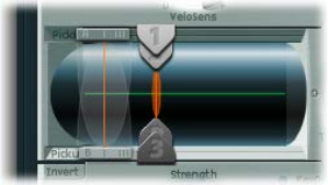
Chapter 13 Sculpture 307
Recreate the sound characteristics of a typical bass instrument
1 Set the Attack value of the amplitude envelope to its minimum value (0.00 ms). The A(ttack)
slider is just to the right of the Material Pad.
2 Shorten the Release time of the amplitude envelope to a value between 4 and 5 ms.
Play a key on your keyboard. The note should stop abruptly when you release the key and should
be free of artifacts (a digital crackle or snap). If you encounter any artifacts, carefully increase the
Release time.
3 Play some sustained notes in the range above E 0. These will die away too quickly. Correct this
quick die-out with the Media Loss parameter by dragging the slider to the left of the Material
Pad almost all the way down to the bottom. Note that the low E string on a high-quality bass can
sound for over a minute.
Your basic bass should simulate a ngered articulation, which means that the sound is created
by striking the strings with ngers.
4 Choose Pick from the Type pop-up menu of Object 1.
Don’t be confused by the name of the object type; despite the name pick, this model is
appropriate for simulating the playing of strings with your ngers.
Play some notes in the lower range. You’ll hear that the sound is very mued, hollow, and
distorted. Before you adjust further parameters in Object 1, you need to set the position of
the pickup.
This is accomplished in Sculpture’s Pickup display located to the left of the Material Pad. You’ll
nd three arrow-shaped sliders, representing Objects 1 to 3. The two transparent bell-shaped
curves help you to visualize the position and width of Pickup A and Pickup B.
On electric basses the pickups are found quite a way o to the side and near the bridge. This
particular bass has only a single pickup.
The behavior of a single pickup is simulated by placing both pickups at exactly the
same position.
5 Drag Pickup B to the exact position of Pickup A while keeping an eye on the help tag. The two
thin orange lines should overlap perfectly. As a suitable value for the example, set both pickups
to 0.10.
Note: Make sure the Invert switch to the lower left of the Pickup display isn’t turned on, because
this would cause the pickups to completely cancel each other out.
It’s now time to determine the playing position.
6 Drag the Object 1 slider in the Pickup display in a horizontal direction. Play the keyboard while
doing so, to hear the changes it makes.
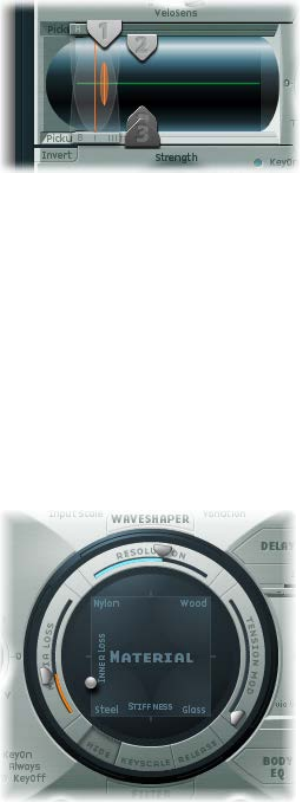
Chapter 13 Sculpture 308
7 You’ll quickly realize that you can achieve a precise, crisp sound only when you drag the slider
relatively far away from the middle of the string. Move Object 1 closer to the pickup (position
0.15 in the gure below).
8 The low notes are still distorted. You can remedy this by adjusting the Level knob to the right of
the amplitude envelope. Set a value of −10 dB.
Recreate the material properties of a set of round wound strings
Although you can already recognize the sound of an electric bass, it doesn’t sound wiry enough
yet. Now it’s time to focus on the bass strings themselves.
1 Drag the ball in the Material Pad up and down at the left edge. Pay attention to how the
overtones react.
Drag the ball to the lower-left corner. The sound should vaguely remind you of the sound of a
low piano string. Because the overtones sustain too long, the tone sounds somewhat unnatural.
2 Drag the ball upward until you hear an acceptable sound. Try the position shown in the gure:
Note: In general, a splaying of the overtones in low wound strings is typical. You can recognize it
by the slightly impure, metallic sound. This occurs because the partials (overtones) are not exact
whole number multiples of the fundamental frequency but rather are shifted somewhat higher.
An example of this eect in the real world of electro-acoustic instruments is the low strings on a
Yamaha CP70. This is overkill, but your bass model will benet from a small amount of this eect.

Chapter 13 Sculpture 309
Splay overtones in Sculpture
1 Drag the ball in the Material Pad gradually to the right.
The sound takes on a more pure, bell-like character.
2 To realistically simulate the splaying of overtones, try the following example setting:
Emulate string and fret vibrations with Object 2
The vibration of a bass string does not occur in a vacuum. The antinode of the string frequently
encounters the natural, physical limitations of the instrument. This is heard as the typical buzzing
and rattling that occurs when the strings touch the frets.
1 Activate Object 2, and choose Bouncing from the Type pop-up menu.
The sound should now vaguely remind you of a mandolin tremolo. This is far too strong an eect
for this kind of sound.
2 Move Object 2 all the way to the right (a value of 1.00).
3 Experiment with Object 2’s parameters. A discrete and realistic result can be achieved with the
following parameter values: Strength 0.33, Timbre −1.00, and Variation −0.69.
Play some low notes, and you’ll nd that once again the overtones sustain a little too long—
somewhat like the lowest notes or strings on a piano. this can be corrected by dampening
the string.
Use Object 3 to dampen overtones
1 Activate Object 3 and choose Damp from the Type pop-up menu.
2 Move Object 3 all the way to the right (value 1.00).
3 Set the Strength parameter to 0.18.
Note: Experiment with how the Strength parameter of Object 3 interacts with the Inner Loss
Material Pad parameter. The higher the Inner Loss value, the smaller the Strength value can be,
and vice versa.

Chapter 13 Sculpture 310
Set the range for the basic bass sound
To more realistically replicate the dierent tonal ranges of the bass, use Sculpture’s
scaling function.
When turned on, the key-scaling function is used to adjust the timbre of the sound, independent
of pitch. Before using the blue sliders to do this, try the Resolution parameter.
mClick the Keyscale button at the bottom of the Material Pad. The key scale below C3 is displayed
in green, the range above in light blue. The Material Pad with its Keyscale parameters activated is
shown here:
Note: The most relevant performance range for basses is found exclusively below C3. For this
reason, you should make use of the green sliders to set the actual timbre of the sound. The
primary sliders found around the ring determine the timbre of the sound above C3. For the
moment, ignore the blue sliders (which control high key scaling) and simply set them to the
same positions as the main sliders.

Chapter 13 Sculpture 311
Rene the basic bass sound
This section covers programming of a basic bass sound, which will serve as the foundation
for the dierent bass sounds you will create. See Program a picked bass sound with Sculpture,
Program a slap bass sound with Sculpture, and Program a fretless bass sound with Sculpture.
Sequentially follow the tasks in this section after reading Program a basic bass sound with
Sculpture to learn how dierent components can be modeled and to gain a fuller understanding
of how Sculpture parameters interact.
Use the Resolution parameter to control the timbre, independent of pitch
The Resolution parameter is normally used to set the balance between DSP load and sound
quality. It can, however, also be used to shape the sound.
1 Play some notes at the higher end of the bass’s range (around C2), then drag the Resolution
slider all the way to the right and then gradually back toward the left.
You can hear how the sound loses overtones yet simultaneously becomes louder. At low
Resolution values, an inharmonic metallic rattling is heard in the sound.
2 Increase the Resolution value until the metallic rattling disappears. Set the slider to the following
position:
3 Play some notes in the bottom range (around E 0). You’ll note that the sound is quite mued
and vintage-like. Move the green Low Keyscale slider (found below the main Resolution slider) all
the way to the right; the low range should now sound a little more wiry.
With most stringed instruments, the overtone content decreases as the pitch becomes higher.
Strictly speaking, this is true only of open strings, and even then in a limited sense. If the strings
are ngered, the length of the string is shortened, especially in the high register, and the eect
becomes more signicant.

Chapter 13 Sculpture 312
Use the Inner Loss parameter to scale the overtone content, dependent on pitch
1 Move the Material Pad ball above the words Inner Loss. Try to move the ball solely in a vertical
direction to maintain a constant Stiness value.
2 Drag the green line next to the ball toward the bottom until the small green diamond is located
directly above the word Steel.
When playing, you’ll recognize the smooth transition that takes place between the wiry,
overtone-rich sound at the bottom end and the extremely dampened sound in the upper
register. This exaggerated setting was chosen to clearly demonstrate the scaling principle in
stringed instruments. To achieve an authentic sound and timbre, try the following setting:
Set sustain levels for the basic bass sound, dependent on pitch
In basses in particular, low notes sustain far longer than high notes. Sculpture allows you to
authentically and convincingly simulate this behavior with the Media Loss parameter.
1 Play a few held notes in the range around C2 and above. You’ll hear that these notes die out
much too slowly. Drag the Media Loss slider up until this range begins to fade out quickly
enough. The downside is that the lower notes now die out too quickly.
2 Drag the green Media Loss Key Scale slider down until the fade-out phase of the lower range is
suciently long.
3 Compare your results with these recommended values:
You’ve now created a basic bass that’s articulated with your ngers. Save this as E-Bass Fingered
Basic. You’ll be using this basic bass as a foundation for the construction of further bass sounds.
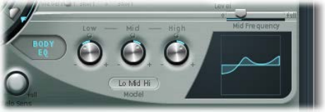
Chapter 13 Sculpture 313
The scope for sound design, by altering the frequency spectrum of electromagnetic instruments,
is far more exible than that oered by acoustic instruments. In addition to the number of
pickups, a major role is also played by the choice of amplier, the equalization setting within
the amplier, and—last but not least—the physical properties of the speakers and their
enclosing cabinet.
The central features of your electric bass sound are complete, but the sound can be improved by
paying close attention to some details. Here are a few general suggestions:
•Vary the position of the pickups. Try placing each of them in dierent positions. This cancels
out certain frequencies, and others are summed together.
•Try turning on the Invert switch, even though this eect is not typical for electric basses.
•What is typical for bass sounds is the placement of the pickups in the outer-left third of
the string model. The farther you move them to the left, the thinner and more nasal the
sound becomes.
•Shifting Object 1 will have a similar eect. Try dierent combinations here as well.
Alter the frequency spectrum of your basic bass with the Body EQ
The Body EQ is ideal for giving the bass sound that nal, nishing touch. Your electric bass sound
could be a little less smooth, and a bit more precise in its attack phase. Bassists like to use the
terms drier and more bite to describe this phenomenon.
1 Load the E-Bass Fingered Basic setting.
2 Choose the standard Lo Mid Hi model from the Model pop-up menu in the Body EQ section.
3 Reduce the low bass frequencies by setting the Low knob to a value of −0.30.
4 Boost the mid-range frequencies substantially by setting the Mid knob to a value of 0.50. Drag
the Mid Frequency slider to a value of 0.26.
5 You’ll probably nd that the boosting of the low mid frequencies is a little too strong at this
point, so return the Mid value to 0.30.
6 The sound could stand to be a little more wiry, so set the High knob to a value of 0.30.
7 To nish o, set the Level knob (to the right of the amplitude envelope) to a value of −3 dB.
The sound is now as loud as possible, without the low notes distorting.
8 Save this sound setting as E-Bass Fingered Basic EQ1.
Chapter 13 Sculpture 314
Program a picked bass sound with Sculpture
The basic bass is played with the ngers. In the following example, you will simulate playing
the strings with a pick, using the Pick object type. The Timbre parameter will be used to adjust
the relationship between the speed and intensity at which the string is struck. The Variation
parameter will be used to dene the virtual material density, or hardness, of the pick.
If you imagine the ngers to be very soft picks, it makes sense to alter the Pick parameters so
that a hard plastic pick is the outcome.
Simulate playing with a pick
1 Load the E-Bass Fingered Basic setting.
2 Set the Timbre parameter of Object 1 to its maximum value of 1.00.
The attack is now stronger.
3 Try several dierent Variation settings to get a feel for the material qualities of the pick.
Note: Not all positions will deliver usable results for the entire range of the instrument.
4 You’ll get a consistent, working setting for the two octaves above E 0 with the following
parameter settings: Position 0.17 (Pickup display), Strength 1.00 (maximum), Timbre 0.90, and
Variation 0.56.
When these settings are used, you’ll nd that the sound has become softer and very thin. In fact,
it’s somewhat reminiscent of a clavinet.
Compensate for thinning side eects with the Body EQ
1 Activate the Body EQ and add a healthy portion of bottom end to the sound by setting the Low
parameter to 0.60. Mid should be set to 0.33.
2 Set the High knob to −0.45 because the sound is now so bright that rolling o a few of the highs
can’t hurt.
3 Bring the volume into line. If you adjust the Level knob to 2.5 dB, nothing should be distorting. If
this isn’t the case, try reducing some more of the bottom end with the Low knob.
4 Save this setting as Pick Open Roundwound.
Chapter 13 Sculpture 315
Emulate bass guitar damping
Playing with a pick is often combined with a damping technique that employs the ball of the
thumb. The right hand, which also holds the pick, should physically lie on top of the strings at
the bridge. This technique results in the sound having less overtone content but becoming
more percussive and punchy at the same time. You can variably control the timbre of the sound
through the angle and pressure of your hand while playing.
Object 3 will be used to emulate the virtual ball of the thumb in this example. The Timbre
parameter determines the kind of damping that occurs, and Variation dictates the length of the
string section that is being dampened.
1 Set the Object 3 type to Damp.
2 Set Object 3’s Strength parameter to 0.50.
3 Move Object 3 a little bit to the right in the Pickup display (to position 0.95) to simulate the
width and position of the ball of the thumb lying on the bridge.
4 Set Timbre to its minimum value (−1.00) to achieve a very soft damping eect.
5 Set the Variation parameter to its maximum value of 1.00.
A metallic ringing occurs during the attack phase and still can be heard in the octave above E0.
6 To suppress the ringing, move the small green diamond on the Material Pad to a position directly
under the ball. In doing so, you’ve just increased the Inner Loss value for the low key range.
Note: To place the diamond exactly under the ball, you can click it while pressing the Option key.
7 Save this setting as Pick Bass Half Muted.
Simulate harmonics created by ngers lightly touching the strings
Harmonics are single partials (overtones) of the overall sound. They can be heard by damping
certain points along the string. This is done by lightly laying the ngers of the left hand
(assuming a right-handed bass player) on the string—not pressing down—before the note is
articulated. The rst overtone, the octave, is achieved by placing your nger at the exact middle
of the string—in eect separating the string into two halves. The next overtone is the fth above
the octave, and the position of your nger should divide the string into a ratio of one-third to
two-thirds. The next overtone separates the string into proportions of one-quarter to three-
quarters, and so on.
1 Object 3 is used as a damper. Choose the Damp type.
2 Adjust Object 3’s Timbre parameter to its maximum value of 1.00.
3 Adjust Variation to its initial value of 0.00 by clicking the Variation slider while holding down the
Option key.
4 Move Object 3 to the exact middle (0.50) of the Pickup display. Play the keyboard, and you’ll hear
the rst overtone as a harmonic.
5 While playing, very slowly move Object 3 toward the left of the Pickup display. In doing this, you
are eectively scrolling through the overtone series, so to speak.
6 Save this setting as Flageolet Xmple.
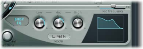
Chapter 13 Sculpture 316
Emulate a vintage at wound pick bass
1 Load the Pick Bass Half Muted setting.
2 Drag the Material Pad ball upward and the sound becomes more mued.
3 Increase the Object 3 Strength parameter to 0.70. The result is a muted pick bass with at
wound strings.
Tip: If you turn o Object 3, you’ll hear a sound that is reminiscent of a 1970s Fender
Precision Bass.
4 Save this setting as Flatwound Pick Damped.
Emulate a Bert Kaempfert-style percussive bass
1 Turn Object 3 back on.
2 Move both pickups a little to the left (position 0.08).
3 Move the virtual pick (Object 1) a little farther to the outside (position 0.10).
4 Enhance the sound with the Body EQ by turning the Low knob to its maximum value (1.00).
5 To remove the smacking in the attack phase, use the graphical display to choose a value of 0.48
for the Body EQ Mid frequency, then use the knob to increase this value to 0.51. Option-click the
Body EQ High parameter to set it to a value of 0.00.
6 Save this setting as Easy Listening Pick Bass.

Chapter 13 Sculpture 317
Program a slap bass sound with Sculpture
You’re actually dealing with two dierent articulations here. The low notes originate when
the thumb literally slaps the strings on the upper part of the ngerboard. The high notes are
produced when the strings are strongly plucked or popped with the ngers. This is achieved by
hooking a nger under the string, pulling it away from the instrument, then allowing it to slap
back onto the ngerboard. In conjunction, these articulation methods make up the typically
aggressive and overtone-rich slap bass sound.
Emulate a slap bass sound
1 Load the E-Bass Fingered Basic EQ1 setting.
2 Turn o the Body EQ.
3 Also turn o Object 2 and Object 3 for now.
Because the basic sound of a slap bass is brighter than a standard ngered bass, you need to
adjust some Material Pad settings.
4 Return the Low Keyscale parameter to its initial value by Option-clicking the small green triangle
(found below the main Resolution slider).
5 Drag the ball down a little, and the sound becomes more wiry. The ball should now be directly
above the word “Steel” on the horizontal axis.
From the models at your disposal, Strike is the most suitable for simulating a thumb physically
striking the strings from above. This model is not, however, as appropriate for the slapped
(popped) strings. It makes the most sense to choose the Pick model for this purpose.
6 To be safe, turn the Level knob to −25 dB.
7 Choose the Pick model for Object 1.
8 Drag Object 1 to position 0.90 in the Pickup display. This position corresponds to a playing
position above or on the ngerboard.
Note: Given its universal concept, Sculpture will not react exactly like a bass, where one would
tend to play in the middle of the string on the upper part of the ngerboard. Try moving
Object 1 to this position and see how it sounds. You’ll nd that the sound is a little too smooth.
Chapter 13 Sculpture 318
Set the parameters for object 1
1 Set Timbre to a value of 0.38, which corresponds to a rapid attack.
Timbre determines the angle of the obstacle to the string.
2 Set the Strength parameter to 0.53.
3 Set the Variation parameter to −0.69.
This denes the softer material that constitutes the eshy part on the side of your slapping
thumb. Put more technically, Variation denes the type and degree of reection.
4 Choose Bound in the Object 2 Type pop-up menu to emulate the typical bright rattling that is
created when the string strikes the ngerboard.
Bound limits the antinode of the string in exactly the same way as the ngerboard on a real
electric bass.
Adjust object 2 parameters
1 Set Timbre to 0.39.
This corresponds to a ngerboard that runs almost parallel to the string.
2 Set the Strength parameter to 0.33.
Note: Try some higher values as well. You’ll see that the sound becomes softer and softer until
it’s completely dampened by the obstacle.
3 Set Variation to 0.64. Despite the overtone-rich reection, the string can still vibrate freely.
Note: Try some negative values—you’ll see that the reections can no longer develop in an
unhindered fashion.
4 Set the Level knob to −3 dB. The Bound obstacle has made the sound softer.
5 Notice that the sound is still too smooth for a real slap bass, so try using the Body EQ again. Turn
on the Body EQ, and adjust the parameters as follows: Low 0.25, Mid 0.43, High 0.51, and drag the
Mid Frequency slider to 0.59.
6 Save this sound as Slap Bass Basic#1.
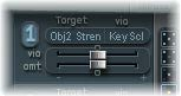
Chapter 13 Sculpture 319
Program a fretless bass sound with Sculpture
With the exception of shared playing techniques, the fretless bass diers from a normal bass
through its buzzing, singing sound. Because the frets on the ngerboard of a standard bass
function as a collection of mini-bridges and allow the string to vibrate in an unobstructed
fashion, the direct collision of the string’s antinode with the ngerboard on a fretless bass is
responsible for its typical sound. The string length on a fretless bass is markedly shorter than
the string length on an acoustic double bass. The upshot of this is that a controlled buzzing
is produced, even when a fretless bass is played with a weak attack. This buzzing can be
consistently reproduced in the high register, even on fretless basses that have very short string
lengths. The use of the comparatively soft tip of your nger—instead of a hard, metallic fret—to
divide or shorten the string also plays a role.
Program a fretless bass
1 Load the E-Bass Fingered Basic EQ1 setting.
2 Turn o Object 3. You’ll come back to it later.
3 Choose Disturb from the Object 2 Type pop-up menu.
Tip: In the Disturb model, the Timbre parameter determines how far the string is deected from
its resting position by the obstacle. Positive values precipitate no deection of the vibration from
its resting position. Variation denes the length of the string section that is disturbed—positive
values correspond to a longer section of string, negative values to a correspondingly shorter
section of string.
4 Adjust Object 2’s parameters to the following values: Strength 0.14, Timbre −0.05, Variation −1.00.
5 Drag the Object 2 slider, which remains at the far right in the Pickup display, to see its value of
0.99. You’ll note that the range between C2 and C3 already sounds quite acceptable, but the
buzzing in the lower notes is still too strong. It is somewhat sitar-like, so keep this disturb model
in mind when it comes to creating a home-spun sitar.
6 Try dierent settings for the Strength parameter for both the higher and lower playing ranges.
You’ll see that, at best, only a compromise is possible. The buzzing is either too loud in the low
range or not present enough in the high range.
Obviously, the eect needs to be scaled over the relevant tonal range. Unlike the parameters for
the string, Objects 1 to 3 don’t have a directly addressable key scaling function. There’s a clever
way around this: Both LFOs oer a key scaling function. As you probably don’t want the buzzing
to be modulated by a periodic oscillation, you need to reduce the LFO speed to innitely slow or
0. In this way, you can deactivate the LFO itself, but still use its modulation matrix.
7 Activate LFO2 by clicking the LFO2 button at the bottom left, and set the Rate knob to a value of
0.00 Hz.
8 Click the 1 button (next to the RateMod slider, to the upper right) to activate the rst
modulation target.
9 Choose Object2 Strength from the Target pop-up menu.
10 Choose KeyScale from the via pop-up menu.

Chapter 13 Sculpture 320
11 Drag the amt slider to the right while you are playing. You will hear that the singing buzzing
fades out in the lower range, while gradually being retained as you move toward C3. Drag the
slider to a value of 0.15. The buzzing is now far more moderate in the low range.
12 Switch Object 3 back on. Set Timbre to its minimum value (−1.00) and Variation to its maximum
value (1.00). Object 3 should be positioned all the way to the right, at a value of 1.00.
13 Vary the Object 3 Strength parameter. You’ll discover that the overtone content of the buzzing
can be controlled very eectively. A Strength value of 0.25 is recommended here.
14 Save this setting as Fretless Roundwound#1.
Add eects to your Sculpture bass sound
Detuning and ensemble eects are normally achieved using a modulation eect or by
combining doubling and detuning. When you are using a fretless bass for a solo part, a broad
chorus eect adds a nice touch.
Because Sculpture can synthesize only one note at a time at any given pitch, simple doubling
isn’t an option. There are, however, alternatives for bringing movement and life into the sound.
Almost all of the type parameters of the dierent objects can be modulated by LFOs, resulting in
a vast number of possible combinations.
As a rule, basses are mixed without eects (dry), but a small amount of reverb can be quite
appealing on a fretless bass, when used as a solo instrument. Use Sculpture’s Delay section to
emulate this. Heavy delays are, however, used on basses in “dub” style reggae.
Emulate a chorus eect by modulating the pickup positions
1 Make sure the Fretless Roundwound#1 setting is loaded.
2 Adjust the position of Pickup B to 0.20.
3 Drag the Spread Pickup semicircle—which is beside the Level knob—upward.
Both of the light blue dots move downward toward the letters L and R.
You can hear how the stereo breadth of the fretless sound has increased. Pickup A is sent out on
the right channel, while Pickup B occupies the left channel.
Note: Although only modern basses oer such stereophonic features, it’s still fun to process
conventional sounds with this eect. Note that not all pickup positions are monophonic-
compatible. You can check this by returning the Spread Pickup setting to monophonic—click the
Spread Pickup semicircle while pressing the Option key.
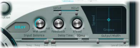
Chapter 13 Sculpture 321
Animate the pickup positions
1 Select LFO1.
2 Click the 1 button (next to the RateMod slider, at the upper right) to activate the rst
modulation target.
3 Choose Pickup Pos A-B as the modulation target.
4 Set the Rate knob to 1.00 Hz.
5 To hear the eect, you need to set the modulation intensity (amount). Familiarize yourself
with this eect by moving the amt slider gradually to the right. Set it to a nal value of 0.15, a
moderate rate that doesn’t wobble too much.
6 Save this setting as Fretless Chorus Dry.
Tip: At the maximum stereo breadth, eects based on detuning are not as prominent, especially
when the beats heard in the sound result from signal dierences between the left and right
channels. This is valid only to a certain degree, because the motion of the pickup doesn’t create
a true chorus or harmonizer eect. Try it out and see what happens when the stereo breadth
is reduced a little. Also test other modulation targets, such as Pickup Pos A+B, Pickup Pan A+B,
Pickup Pan A−B, and String Stiness.
Create an unobtrusive atmospheric space
This example shows that the Delay section can be used as a substitute reverb for small spaces.
For sophisticated reverb eects, it’s best to process Sculpture’s output with a reverb plug-in.
1 Load the Fretless Chorus Dry setting.
2 Click the Delay button to turn on the Delay section.
3 Drag the Input Balance slider to 1.00.
4 Click the small Sync button—directly to the right of the Delay Time slider—to deselect it, which
switches o the tempo synchronization of the delay.
5 Drag the Delay Time slider to 90 ms.
6 Set the Xfeed knob to 0.30.
The individual reections are still too brash. To make the eect more discrete and
unobtrusive, adjust the frequency spectrum and amplitude of the reections. Start with the
frequency spectrum.
7 Drag the LoCut slider to 200 Hz and the HiCut slider to 1000 Hz in the Delay section.
The LoCut parameter at 200 Hz excludes the low frequencies in the reections, thus preventing
a muddy sound. The comparatively drastic cut to the highs with the HiCut parameter blurs the
individual reections, thereby creating the impression of a small room with soft surfaces.
8 Set the Wet Level knob to 25% to reduce the total level of the eect.
9 Save this setting as Fretless Chorus+Ambience.
Chapter 13 Sculpture 322
Create a “drowned in delay” eect
1 Reload the Fretless Chorus Dry setting.
2 Switch the Delay section on.
3 Drag the Input Balance slider all the way to the right, to 1.00.
4 Set the Delay Time value to 1/4t (quarter-note triplet).
5 Set the Feedback knob to a value of 0.20.
6 Adjust the Xfeed knob to a value of 0.30.
7 Drag the LoCut slider to 200 Hz and the HiCut slider to 1600 Hz.
8 Now adjust the overall level of the eect—try setting the Wet Level knob to a value of 45%.
9 Vary the stereo position and rhythmical structure of the delay, by moving the small light blue
diamond around the Delay Pad.
10 Save this setting as Fretless Chorus+Wet Delay.
Chapter 13 Sculpture 323
Advanced Sculpture tutorial: synthesizer sounds
Synthetic sound programming overview
The Electric bass programming overview on page 305 section covers programming of natural
bass sounds by authentically reproducing the real physical interaction that occurs between
a string and the exciting agent that acts upon it. While producing such lifelike models is
undoubtedly a forte of Sculpture’s architecture, its sonic capabilities extend to the creation of
very dierent sounds as well.
Sculpture contains a number of functions you can use to create new and novel synthesized
sounds. This includes the Morph Pad, which can be automated, as well as recordable and
programmable envelopes that can be used in a rhythmic context. See Create morphed sounds
in Sculpture.
Such features are usually unnecessary when reproducing natural bass sounds, because no
electric bass that exists can alter the tonal characteristics of the string during the decay phase
of a note—perhaps from wood to metal—and rhythmically synchronize this change to the
tempo of the project. These functions are useful, however, when creating sustained, atmospheric
sounds where slow and interesting modulations help them come alive. See Create a sustained
synthesizer sound with Sculpture.
Create a sustained synthesizer sound with Sculpture
First, load Sculpture’s default setting—the very simple sound consisting of a plucked string
that vibrates and fades away. This sound needs some drastic changes to become a sustained or
extended pad sound.
Examine the three objects. Notice that only Object 1 is active, and acts on the string with an
Impulse object type: the string is briey excited when the note is played, then the sound decays.
A sustained pad sound requires an exciting agent that constantly acts upon the string. The
appropriate object types are Bow or Bow wide (the string is played with either short bow strokes
or long, extended bow strokes), Noise (excited by a random noise signal), or Blow (excited by
being blown—much like a clarinet or ute).
Test the above mentioned object types one after the other. Drag the Object 1 Pickup slider,
responsible for the exact position of the exciting agent, up and down the string while you’re
playing. You will come to two conclusions: First, the sound is now sustained for as long as you
hold down a key. Second, dragging the Object 1 slider with the Bow type selected results in
the most pronounced sonic changes. This setting promises the most rewarding possibilities for
varying the sound, and that’s why this type has been chosen.
The sonic variations created by the Bow type are very appealing when the virtual bow stroke is
moved along the string. You can control this movement by using an envelope, thus creating the
foundation of your pad sound.
It makes more sense and is more convenient to record the envelope rather than program it, even
if it is easy to program it with the graphic display.
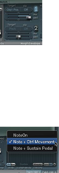
Chapter 13 Sculpture 324
Record an envelope
1 Make sure you have loaded the default setting, then drag the Object 1 slider all the way to the
left. Starting from this position, where it generates only an overtone-rich scratch, start animating
it by using the envelope.
2 Locate the Envelope section in the lower-right corner of the Sculpture window. Select the rst of
the two envelopes by clicking the envelope 1 button to select it. In the left part of the Envelope
section, notice the two routing possibilities that are used to assign a modulation target to
the envelope.
3 Click the 1 button to activate the rst routing link, and choose Object1 Position from the Target
pop-up menu as the modulation target. Drag the amt slider all the way to the right to set the
modulation intensity to its maximum value.
The envelope can now be recorded. It is assumed that your MIDI keyboard has a modulation
wheel that outputs the corresponding MIDI controller message (CC number 1) and that option
1 ModWhl is selected for control of Envelope 1 (choose 1 ModWhl from the CtrlEnv 1 pop-up
menu in the dark bottom edge of the Sculpture window).
4 Click the R button near the top of the Envelope section below Record Trigger, to prepare the
envelope for recording. Choose Note + Ctrl Movement from the Record Trigger pop-up menu.
This option species that the recording of the controller messages from the modulation wheel
begins the instant the rst note is played.
5 Play a note when you want to start the recording, and move the modulation wheel slowly
upward while keeping the key on the keyboard depressed. Notice the sound variations you
create while moving the modulation wheel.
6 At the end of the recording, return the wheel to its initial starting position and, after you release
the depressed note, click the R button to deactivate the recording mode.

Chapter 13 Sculpture 325
Increase stereo breadth and chorus
To give the very dry-sounding “0001 raw pad” setting a little more stereo breadth and chorus
eect, modulate the Pickup positions, and assign them to the left and right channels.
1 Load the “0001 raw pad” setting.
2 Drag the Spread Pickup semicircle upward until the light blue dots come to rest near the line
that separates both semicircles.
This separates the stereo pan positions of the Pickups.
3 Click the 1 and 2 buttons to activate both of the modulation links in LFO1.
4 For the rst link, choose PickupA Position from the Target pop-up menu, and then drag the amt
slider to a small positive value of about 0.03 Hz to modulate the position of Pickup A.
5 For the second link, choose PickupB Position from the Target pop-up menu, and then drag the
amt slider to a small negative value of about −0.03 Hz to modulate the position of Pickup B.
You will hear a pleasant beating or chorus eect in the sound, which makes it broader and more
full, alleviating the unpleasant, dry character. Another unpleasant aspect is that the sound is too
strong in the mid frequency range and could use some equalization. You can use the Body EQ to
correct this.
6 Activate the Body EQ, and experiment with the Lo Mid Hi model—the standard setting. Try
reducing Mid to −0.5 and dragging the Mid Frequency slider to 0.37.
7 To give the pad a little depth, activate the Delay. Set the Delay Time to 1/4 and adjust the Xfeed
knob to 30%.
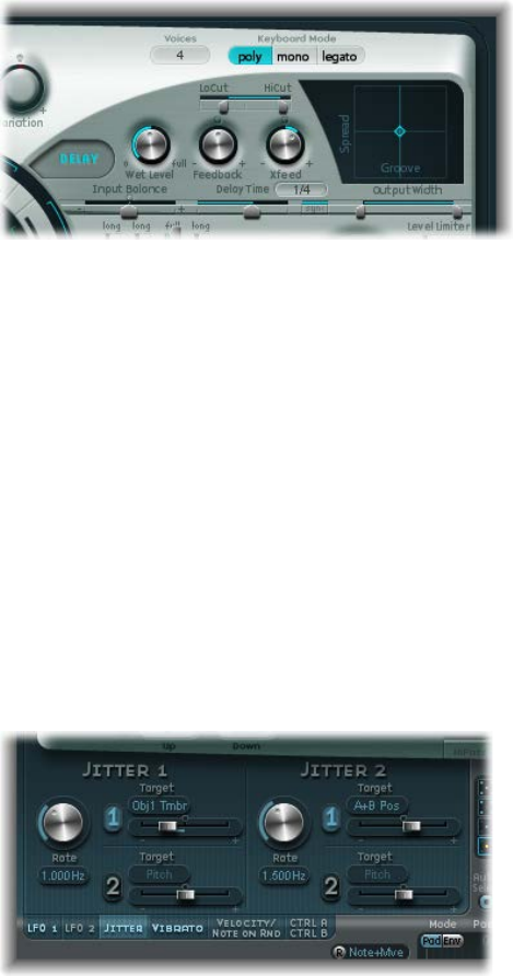
Chapter 13 Sculpture 326
The pad now has a pleasant and unobtrusive ambience; you can leave the other Delay
parameters at their original values.
Make the sound more lively using the jitter modulators
You can make the sound more animated with some subtle modulation, which makes the jitter
modulators the perfect tool for the job. The jitter modulators are basically LFOs that use a
random waveform.
1 Click the Jitter button below the LFO section to activate the display for both of the
jitter modulators.
2 Click the 1 button to turn on the rst link in Jitter 1, and choose Object1 Timbre from the Target
pop-up menu.
3 Drag the slider below the Target pop-up menu to −0.40 to adjust the Intensity, and reduce the
Rate parameter to 1 Hz. There should be subtle inconsistencies in the pressure applied by the
bow to the string. To better recognize this eect, temporarily increase the Intensity level.
You can use the second jitter modulator for random position deviations with the modulation
target Pickup Pos A+B (pickup position A and B).
4 Activate Jitter 2 and choose the Pickup Pos A+B setting from the Target pop-up menu.
5 Drag the slider below the Target pop-up menu to an Intensity of about 0.2, and adjust the Rate
knob to 1.5 Hz. As you increase the Intensity, the sound develops a distinct clinking or rattling—
adjust this eect to taste.
You now have a satisfactory pad sound, which you should leave alone at this point, even though
a few Sculpture features such as the Filter and the Waveshaper lie idle—not to mention the two
additional Objects—but sometimes it’s a good idea to quit while you’re ahead.

Chapter 13 Sculpture 327
Create morphed sounds in Sculpture
The Morph Pad is in the middle of the lower part of Sculpture’s window. Each corner of the
Morph Pad can contain a dierent setting for a diverse number of parameters. You can cross-
fade between these settings and morph the sound by dragging the red ball in the center of the
Morph Pad.
Vary the sound with the Morph Pad
1 To start, Control-click the Morph Pad, then choose Paste to all Points from the shortcut menu
to copy the current setting into all four corners of the Morph Pad. (If Paste to all Points is
unavailable, rst choose Copy selected Point.)
2 Drag the ball to one corner to select the corresponding partial sound, indicated by highlighted
arches that appear in the corner.
3 Adjust several parameters.
4 Repeat steps 2 and 3 in each corner.
5 Carefully drag the ball around the Material Pad to nd a position where your pad sound takes on
a new and interesting character. Also try the extreme corners, for example.
After you choose dierent settings for the Morph Pad corners, moving the morph ball creates
marked sound variations—even though the intermediate stages do not all exhibit a tonal
character. You can automate the morphing process by assigning two MIDI controllers to the
MorphX and MorphY pop-up menus at Sculpture’s bottom edge. You can also automate the
Morph Pad using a recorded envelope (for more information, see Record Morph Envelopes in
Sculpture on page 288).
Use the randomizing function
On each side of the Morph Pad there is a randomizing feature that randomly varies sounds to a
chosen intensity level, or amount of randomization. This is especially useful for subtle changes to
natural sounds, but it can also provide for rewarding variations to synthesized sounds as well.
1 Select one of the squares on the left side of the Morph Pad to determine the number of corners
that are to be varied.
2 To adjust the intensity of the random deviations, drag the slider on the right side of the
Morph Pad.
3 Click the Rnd button at the top of the slider to perform the randomization.
When you next move the morph ball, you’ll hear the variations you just created.
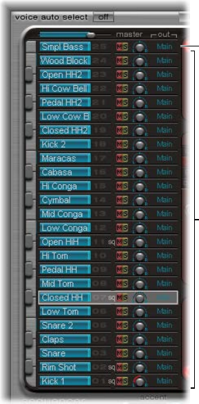
328
Ultrabeat overview
Ultrabeat is a synthesizer that is designed to create percussive sounds and polyphonic rhythms. It
also incorporates a powerful, integrated step sequencer, which you can use to create polyphonic
rhythmic sequences and patterns. See Ultrabeat step sequencer overview.
Most software synthesizers oer one synthesizer per plug-in instance. Ultrabeat, however, places
25 independent synthesizers at your disposal. These synthesizers—known as drum voices in
Ultrabeat—are optimized for the generation of drum and percussion sounds.
You can compare Ultrabeat with a drum machine that features 24 drum pads, plus a built-in
multioctave keyboard that can be used for polyphonic accompaniments, or bass or melody lines.
See Play and select Ultrabeat drum sounds.
The distribution of drum voices across the MIDI keyboard is as follows: a single drum voice
is assigned to each of the rst 24 MIDI keys (spanning MIDI notes C1 to B2). The 25th drum
voice is assigned to the keys from the 25th MIDI key (C3) and above, enabling you to play this
sound chromatically.
Drum voices 1 to 24
25th drum voice can be
played chromatically.
Ultrabeat 14

Chapter 14 Ultrabeat 329
Ultrabeat’s 24-drum pad assignment is compatible with the widely adopted GM (General MIDI)
MIDI Drum note mapping standard. If your MIDI keyboard is limited to two octaves or does not
support transposition, use the Transpose parameter of your host application to shift incoming
MIDI notes up or down one or more octaves.
Note: For clarity, and to maintain the drum machine analogy, this guide refers to the
independent synthesizers as drum sounds. A combination of drum sounds forms a drum kit.
Ultrabeat interface
Ultrabeat’s user interface is divided into three main sections.
Step sequencer
Synthesizer section
Assignment section
•Assignment section: Displays all drum sounds in a drum kit. You can select, name, and organize
drum sounds here. This section also includes a small mixer, used to adjust the level and pan
position of each sound. See Ultrabeat Assignment section overview on page 330.
•Synthesizer section: Used to create and shape individual drum sounds. The parameters of the
drum sound selected in the Assignment section are displayed in the Synthesizer section. See
Ultrabeat Synthesizer section overview on page 338.
•Step sequencer: Used to create and control sequences and patterns. A sequence triggers a
single drum sound, and can consist of up to 32 steps. A pattern contains the sequences for
all 25 sounds. You can trigger and control sounds with the step sequencer in place of—or
in addition to—MIDI notes entering Ultrabeat from your host application or keyboard. See
Ultrabeat step sequencer overview on page 370.
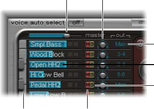
Chapter 14 Ultrabeat 330
Ultrabeat Assignment section
Ultrabeat Assignment section overview
The Assignment section displays all sounds in a drum kit. You can:
•Select, organize, and name sounds
•Import sounds from other Ultrabeat settings or EXS instruments
•Set relative levels and pan positions for each sound
•Mute or solo sounds in the drum kit
Master Volume
slider Pan knob
Output pop-up menu
Volume slider shown
below sound name
Keyboard Mute button
Solo button
Assignment section parameters
•Master (Volume) slider: Controls the levels of all drum sounds in the drum kit—the overall mix
level of all drum sounds.
•Volume slider: Drag the blue slider to set the volume for the sound. All drum sound levels are
indicated by blue sliders, providing an overview of relative levels within the kit.
•Keyboard: Acts as a display when MIDI information is received. Click the keys to play the sound
on the corresponding row.
•M(ute) buttons: Click to mute (silence) one, or multiple, sounds in the drum kit.
•S(olo) buttons: Click to hear one, or multiple, drum sounds in isolation. All other drum sounds
(unsoloed) are muted.
•Pan knobs: Rotate to position drum sounds in the stereo eld (panorama).
•Output pop-up menus: Use to independently route each drum sound to individual outputs, or
output pairs. Ultrabeat features eight separate stereo and mono outputs when inserted as a
multi-output instrument.
•Drum sounds that are routed to an output pair other than Main (1–2) are automatically
removed from the main output channel strips.
•Choosing an output pair other than Main (1–2) routes the sound to an aux channel strip.
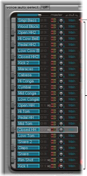
Chapter 14 Ultrabeat 331
Play and select Ultrabeat drum sounds
The 25 sounds of an Ultrabeat drum kit are mapped to the onscreen keyboard at the left side of
the Ultrabeat interface. Sounds start from the bottom of the onscreen keyboard and correspond
to note values on a connected MIDI keyboard, starting at C1.
Drum voices 1 to 24
25th drum voice can be
played chromatically.
Play a drum sound
Do one of the following:
mPlay a note on a connected MIDI keyboard.
mTo trigger the sound on the adjacent row, click a key on the onscreen keyboard.
The corresponding key of the keyboard beside the drum sound name turns blue when it is
clicked or when it receives MIDI information.
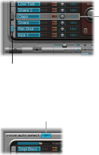
Chapter 14 Ultrabeat 332
Select a drum sound
mClick the name of the sound in the Assignment section.
The selected sound is indicated by the gray frame around the assignment row. The parameters of
the selected sound are shown in the Synthesizer section to the right. See Ultrabeat Synthesizer
section overview on page 338.
The image below shows drum sound 2 being played (indicated by the blue key) while drum
sound 4 is selected (the gray frame).
The highlighted key
(blue) indicates an
incoming MIDI note or
controller message.
The selected sound
is indicated by a gray
frame.
Select a sound by playing your MIDI keyboard
mTurn on Voice Auto Select to select sounds by playing your MIDI keyboard.
Click here to enable
MIDI sound selection.

Chapter 14 Ultrabeat 333
Name, swap, and copy Ultrabeat drum sounds
This section outlines the steps required to rename and rearrange the positions of drum sounds
within a drum kit.
Rename a sound
1 Double-click the name of a sound to open a text entry eld.
2 Enter the name and press Return, or click anywhere outside the text entry eld, to complete the
naming operation.
You can swap and copy drum sounds within an Ultrabeat kit by using a drag-and-drop or
shortcut menu operation.
Swap or copy drum sounds using drag and drop
mDrag the sound name to the target position (do not click a button or menu).
The target is shaded as you drag across the list of sound names.
•A standard drag-and-drop operation swaps the two drum sounds (including Mixer
settings: volume, pan, mute, solo, and output conguration). Sequences are not swapped.
•Command-drag to swap the two drum sounds and sequences.
•Option-drag to copy the sound. Sequences are not copied.
•Command-Option-drag to copy the sound and sequences.
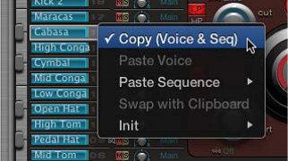
Chapter 14 Ultrabeat 334
Swap or copy drum sounds using a shortcut menu command
1 Control-click or right-click the sound name.
2 Choose one of the following commands from the shortcut menu:
•Copy (Voice & Seq): Copies the selected sound, including mixer settings and all sequences, to
the Clipboard.
•Paste Voice: Replaces the selected sound with the sound from the Clipboard but does not
replace existing sequences.
•Paste Sequence > (submenu): Enables you to replace all, or individual sequences, of the target
drum sound. Sound parameters are not aected.
•1 to 24: A single sequence replaces the currently active sequence (as set in the Pattern menu)
of the target drum sound. This enables you to copy sequences into any of the 24 possible
pattern locations.
•All: Replaces all sequences. In situations where a sound only has several sequences (not all 24
are used), “Paste Sequence > all” places these sequences into the same positions; sequence 5
(in the Pattern menu) is pasted to position 5 in the target sound, for example. If a sequence
exists at this location in the target sound, it is replaced. If no sequence exists at this location,
the copied sequence is added to the target sound.
•Swap with Clipboard: Exchanges and replaces the selected sound with the sound from
the Clipboard.
•Init > (submenu): Opens a submenu that contains a few starting-point (Init) sounds. Select one
of these to replace the target drum sound. The Sample Init sound initializes the lter and pitch
parameters to neutral settings, which are ideal as a starting point for programming sample-
based drum sounds.
These commands aect only the selected drum sound. The sequence and sound data of the
other 24 sounds are unaected.
Note: The shortcut menu commands Paste and Swap with Clipboard require an initial Copy
command—to place data in the Clipboard—before you can use them.
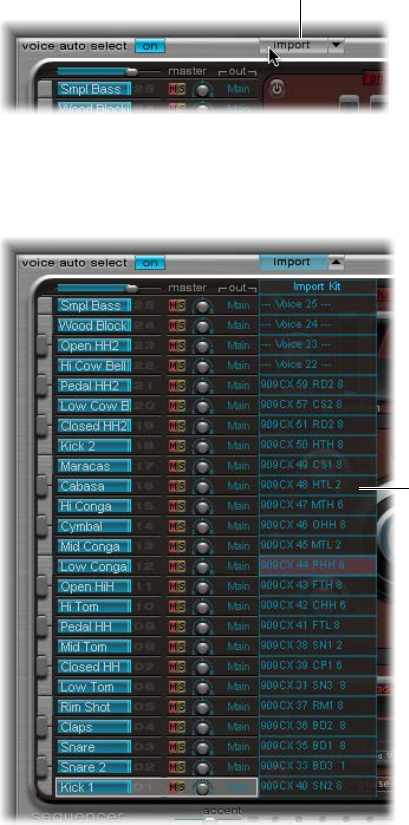
Chapter 14 Ultrabeat 335
Import sounds and EXS instruments into Ultrabeat
Ultrabeat can directly import EXS instruments, in addition to loading audio samples and its
own settings. This provides enhanced sound design and rhythm processing options for EXS
instruments, along with the ability to play and control EXS drum kits with Ultrabeat’s intuitive
drum mixer layout.
There are two key elements that you use to import sounds and sequences into Ultrabeat:
•Import button: Click to choose a kit that contains sounds or sequences you want to import.
•Import list button/Import list: Click to hide/show the import list, then add drum sounds/
sequences from Ultrabeat settings/EXS instruments to your active kit.
Open an Ultrabeat setting or EXS instrument with the import list
1 Click the Import button.
Click here to import a
sound from another
Ultrabeat drum kit or
EXS sampler instrument.
2 Select the source Ultrabeat setting or EXS sampler instrument in the dialog, then click Open.
A list of all sounds found in the selected setting, or samples in the EXS instrument, is shown to
the right of the Assignment section Mixer.
Import list

Chapter 14 Ultrabeat 336
Note: If you import EXS instruments that include more than 25 sample zones, you can navigate
through pages (of 25 zones) by using the up and down arrows to the left and right of the EXS
instrument name at the top of the import list.
Click the arrows to
navigate to additional
pages of sounds.
Drag sounds into your drum kit
mDrag the sound name from the import list into the target row in the Mixer section.
Note: Hold down the Command key to include all sequences.
Transfer sounds using shortcut menu commands
1 Control-click (or right-click) the sound name in the import list, then choose Copy (Voice & Seq)
from the shortcut menu.
The selected sound and its sequences are copied to the Clipboard.
2 Control-click (or right-click) the sound you want to replace in the current drum kit, then choose
one of the following shortcut menu commands:
•Paste Voice: Replaces the selected sound with the sound from the Clipboard but does not
replace existing sequences.
•Paste Sequence > (submenu): Opens a submenu that enables you to replace all, or individual
sequences, of the target drum sound. Sound parameters are not aected.
Pasting a single sequence replaces the currently active sequence (as set in the Pattern menu)
of the target drum sound. This allows you to copy sequences into any of the 24 possible
pattern locations.
•Swap with Clipboard: Exchanges and replaces the selected sound (and associated sequence)
with the sound from the Clipboard.
Import an EXS instrument into Ultrabeat
mDrag an EXS instrument lename from the Finder directly onto the Assignment section.
Ultrabeat reproduces the EXS layout as closely as possible. Layered EXS zones are set up as
layered drum sounds, using the sample playback mode of oscillator 2. See Use Ultrabeat
oscillator 2 sample mode on page 345.
Note: This method does not allow paging through the EXS instrument if it contains more than
25 sounds (samples). Ultrabeat maps only sample zones and layers that fall within Ultrabeat’s
drum sound range of C1 to C3. All other samples (zones) are ignored.
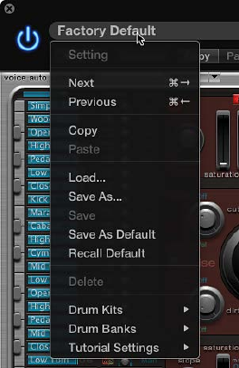
Chapter 14 Ultrabeat 337
Ultrabeat settings
Ultrabeat settings are saved and loaded in the same way as other instruments.
An Ultrabeat setting contains:
•The drum kit, which consists of 25 drum sounds, including assignment and mixer settings.
•The complete parameter settings of all 25 sounds
•The sequencer settings and all patterns, including step automation, trigger, velocity, and gate
information for all 25 sounds
The joint recall of all this information when loading an Ultrabeat setting is practical because the
musical eect of the patterns, especially those with sequenced gate and velocity parameters, is
often tightly tied to the tones of the sounds being used.
Note: When you save a drum kit with the Settings pop-up menu, only the location of the sample
is saved with the setting. An Ultrabeat setting doesn’t save the audio les—merely a reference to
their hard disk location. If you load a setting that contains a reference to a sample that has been
moved or erased, a dialog prompts you to specify or nd the sample. To avoid this problem, you
can use the Finder to create and manage a dedicated Ultrabeat sample folder—for all sounds
and kits.
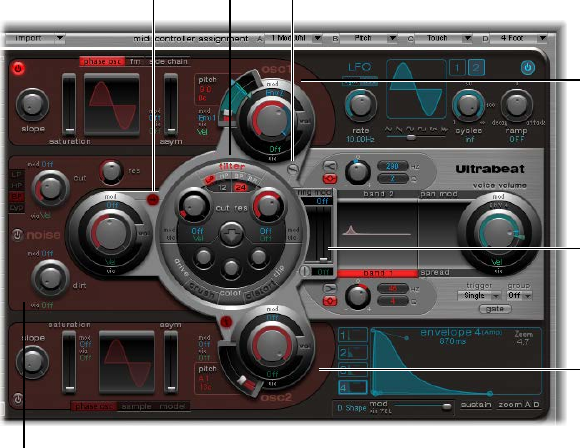
Chapter 14 Ultrabeat 338
Ultrabeat Synthesizer section overview
Ultrabeat’s sound engine is optimized for creating electronic and acoustic drum and percussion
sounds. It combines several synthesis approaches—phase distortion, sample playback, FM
(frequency modulation), and physical modeling—to create tones. You can also use an audio side-
chain input as a sound source. The sound engine provides comprehensive modulation functions,
enabling nearly every Ultrabeat element to be modulated.
The Synthesizer section is the heart of Ultrabeat. Each drum sound in a drum kit is
an independent synthesizer and has its own set of synthesizer parameters—its own
synthesizer section.
The interface and signal ow of Ultrabeat’s synthesis engine are based on classic synthesizer
designs. If you’re new to synthesizers, it might be best to start with Synthesizer basics
overview on page 472, which will introduce you to the fundamentals and terminology of
dierent synthesis systems.
The Synthesizer section runs from left to right, following the layout and signal ow of a
subtractive synthesizer. The basic tonal material is created by the oscillators, noise generator, and
ring modulator. A lter then takes away certain frequencies from the raw sound, followed by
volume shaping–envelopes.
Note: Although the structure and layout mirrors classic subtractive synthesizer designs, Ultrabeat
incorporates a number of dierent tone generation (synthesis) methods, including frequency
modulation, component modeling, sample playback, and phase distortion. These provide unique
qualities that greatly expand the range of sounds you can create.
Oscillator 1
Oscillator 2
Ring
modulator
slider
Signal flow button Filter Signal flow button
Noise generator
The details of Ultrabeat’s functions and their importance become more apparent when you look
at the three-dimensional nature of the interface and recognize the dierent levels from front to
back. The following descriptions refer to the third dimension, so keep this in mind while reading
and exploring Ultrabeat’s interface.
The large, round, elevated Filter (and Distortion) section is in the center. Its placement and
design are both symbolic and practical, as the lter plays a central role in Ultrabeat. The Filter is
discussed in Use Ultrabeat’s lter section on page 351.
Chapter 14 Ultrabeat 339
The Filter receives its signal from the following sound sources: oscillator 1, oscillator 2, the noise
generator, and the ring modulator. The outputs of these sources are represented by the three
round objects, and the rectangular ring modulator section to the right, that surround the Filter.
One level down—from front to back—each sound source output object provides modulation
controls. These determine how modulation sources, such as the LFO and envelopes, aect each
sound source. See Ultrabeat modulation overview on page 360.
Each sound source also features a small Signal Flow button (red, when active). This is used to
determine (and indicate) whether the signal of the associated sound source should proceed
through the Filter or bypass it—before being routed to Ultrabeat’s Output section.
The Output section is shown to the right. Signals sent from the Filter can pass through two
equalizers and a stage for stereo expansion or panoramic modulation. You can also set the initial
output level and trigger behavior in this section. See Ultrabeat Output section overview on
page 355.
The output of the drum sound is then sent to the Assignment section mixer. See Ultrabeat
Assignment section overview on page 330.
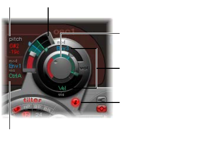
Chapter 14 Ultrabeat 340
Ultrabeat sound sources
Ultrabeat oscillator overview
Ultrabeat oscillators are used to generate waveforms. oscillator 2 can use a sample in place of a
waveform. The signal of one or both oscillators is then sent to other portions of the synthesizer
engine for shaping, processing, or manipulation.
•Oscillator 1 can be frequency-modulated by oscillator 2, for FM synthesis sounds.
•Oscillator 2 can be ring-modulated with oscillator 1.
•Oscillator 2 can use an audio le (a sample), in place of a synthetic waveform. The sample is
output as the oscillator 2 signal.
Other sound sources include a separate noise generator and ring modulator that can produce
additional signals to those generated by the oscillators. See Ultrabeat ring modulator on
page 349 and Ultrabeat noise generator on page 349.
Common oscillator parameters
These parameters are available to both oscillators.
Signal Flow button
Pitch field
Volume knob
Pitch slider
Mod and “via” menus
(for volume)
Mod and “via” menus
(for pitch)
•Oscillator on/o button: Click the button (at the top left of oscillator 1 or bottom left of
oscillator 2) to turn each oscillator on or o independently.
•Volume knob: Sets the level of oscillator 1 or 2. Volume can be modulated by the sources found
in the mod and pop-up menus.
•Pitch slider and eld: Drag to set the oscillator pitch in semitone steps. Press Shift to adjust the
pitch in cent intervals (1 cent = 1/100th semitone). Pitch can be modulated by the sources
found in the mod and via pop-up menus.
•Signal Flow button: Click to route the signal of the associated oscillator through the lter, or
directly to the EQ (in the Output) section. When turned on, the button is lit and an arrow
indicates the direction of the signal ow.
•mod and via pop-up menus: Determine the modulation sources for oscillator pitch and level.
See Ultrabeat modulation overview on page 360.
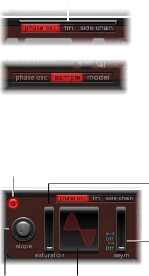
Chapter 14 Ultrabeat 341
Switch between Ultrabeat oscillator synthesis modes
Oscillator 1 can be switched between three dierent synthesis engines: phase oscillator, fm, and
side chain (external audio input), which extends your sonic palette signicantly. Each mode
(engine) provides dierent parameters and features.
Oscillator 2 can be switched between three dierent types of synthesis engines: phase oscillator,
sample, and model. Each mode oers dierent parameters and features.
mClick a button on the upper edge of oscillator 1 to select a mode (synthesizer engine).
mClick a button on the lower edge of oscillator 2 to select a mode (synthesizer engine).
Click the appropriate
button (on the upper
edge of oscillator 1) to
enable each mode.
Ultrabeat oscillator 1 phase oscillator mode
The waveform of the phase oscillator can be reshaped into almost any basic synthesizer
waveform. The eects of parameter changes are immediately reected in the waveform display.
See Create classic waveforms with Ultrabeat’s phase oscillator.
On/off button
Slope knob Waveform display
Asym slider
Saturation slider
Phase oscillator parameters
•Slope knob: Rotate to set the slope or steepness of the waveform. The higher the value, the
steeper the waveform. The resulting sound takes on an increasingly nasal character as the
incline becomes more vertical.
•Saturation slider: Move to Increase the gain, eventually causing the waveform to clip. Higher
values result in a distortion of the waveform shape, making it more rectangular. This results in
a corresponding increase in odd-numbered overtones.
•Asym(metry) slider: Move to change the waveform angle. Higher values skew the waveform
toward a sawtooth wave. Asym can be modulated by the sources shown in the mod and
via pop-up menus, enabling dynamic sound changes at the oscillator level. See Ultrabeat
modulation overview on page 360.
Note: Oscillator 2’s phase oscillator operates in a nearly identical fashion to the phase oscillator
of oscillator 1. The key dierence is that Saturation can be modulated in oscillator 2, rather than
Asymmetry (in oscillator 1). This means that when both oscillators are in phase oscillator mode,
they can produce dierent sounds.
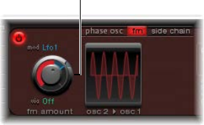
Chapter 14 Ultrabeat 342
Use Ultrabeat oscillator 1 FM mode
FM (frequency modulation) synthesis is well suited for creating bell-like digital tones and metallic
sounds. The principle of frequency modulation (FM) synthesis was developed in the late 1960s
and early 1970s by John Chowning. It was popularized by Yamaha’s range of DX synthesizers in
the 1980s. Although Ultrabeat can’t be compared with the DX series in the discipline of pure
FM synthesis, it can achieve some of the signature sounds of these instruments.
In pure FM synthesis, the frequency of one signal generator, or oscillator, is altered (modulated)
by another signal generator. Positive values from the second generator increase the frequency of
the rst generator. Negative values decrease the frequency.
In a synthesizer, this type of modulation takes place in the audible range. Depending on the
design of the instrument, you can hear the signals of either the rst oscillator alone (being
modulated by the other oscillator), or both oscillators. The interaction between the two
generators alters the waveform signal of the rst oscillator and introduces a number of new
harmonics. This harmonic spectrum can then be used as the source signal for further sound
processing, such as ltering, envelope control, and so on. See Frequency modulation (FM)
synthesis on page 493.
In Ultrabeat’s FM synthesis mode, oscillator 1 (the carrier) generates a sine wave. The frequency
of oscillator 1’s sine wave is modulated by the waveform of oscillator 2 (the modulator).
•When oscillator 2 outputs a positive (or higher) frequency signal, the frequency of
oscillator 1 increases.
•When oscillator 2 outputs a negative (or lower) frequency signal, the frequency of
oscillator 1 decreases.
The net eect of speeding up or slowing down the frequency of oscillator 1 in each waveform
cycle is a distortion of the basic wave shape. This waveform distortion also introduces a number
of new, audible, harmonics. The more complex the oscillator 2 waveform, the more partials are
created by increasing FM Amount. Watch the display to see how the sine wave takes on an
increasingly complex shape.
Important: The impact of any frequency modulations depends on both the frequency ratio and
the modulation intensity of the two oscillators.
Set the frequency ratio and adjust the modulation intensity
1 Turn on FM mode for oscillator 1.
2 Turn on oscillator 2.
3 Adjust the Pitch parameter values of one, or both, oscillators.
4 Adjust the amount (intensity) of frequency modulation with the FM Amount knob.
FM Amount knob
FM Amount can be modulated by the sources shown in the mod and via pop-up menus. See
Ultrabeat modulation overview on page 360.
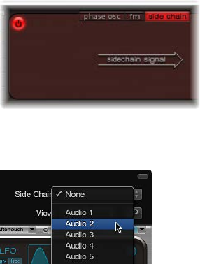
Chapter 14 Ultrabeat 343
Use Ultrabeat oscillator 1 side chain mode
In side chain mode, Ultrabeat uses an external side-chain input as the source for oscillator 1.
The signal of any audio channel strip, bus, or live input can be routed through Ultrabeat’s lters,
envelopes, LFO, and step sequencer. Using busses as side-chain sources makes it possible to
route signals to the side-chain input from any channel strip type that oers busses as outputs
or sends. This includes software instrument channel strips, aux channel strips, or a mix of
multiple channel strips that are routed into a common aux (subgroup), that has a bus as the
output destination.
This feature enables you to use an audio input from oscillator 1, along with the synthesis engine
of oscillator 2, to create a part live audio, part synthesized drum sound, for example. As another
creative option, you could use one drum sound in a kit to lter an external audio signal with a
sequenced groove.
There are two points to note about side-chain use in Ultrabeat:
•The side chain aects only the selected drum sound—Ultrabeat’s other drum sounds and
sequences are not altered.
•A side-chain audio signal alone is not enough to trigger Ultrabeat. To hear the side-chained
audio signal, you need to make sure that Ultrabeat is triggered by MIDI or the internal
step sequencer.
Use Ultrabeat’s side chain
1 Turn on the side chain for oscillator 1.
2 Choose the channel strip that you want to use as the side chain input source from the Side Chain
pop-up menu at the top of the plug-in window.
3 Start playback of your audio source/host application.
4 Play a note on your MIDI keyboard (that corresponds to the side-chained drum sound).
Alternatively, you can use the step sequencer to play a pattern for the side-chained drum sound.
Chapter 14 Ultrabeat 344
Use Ultrabeat oscillator 2 phase oscillator mode
The waveform of the phase oscillator can be reshaped into almost any basic
synthesizer waveform.
Oscillator 2 operates in a nearly identical fashion to oscillator 1 when in phase oscillator mode.
The key dierence is that Saturation can be modulated in oscillator 2, rather than Asymmetry in
oscillator 1. This results in the production of dierent sounds when both oscillators are in phase
oscillator mode.
Phase oscillator parameters
•Slope knob: Rotate to set the slope or steepness of the waveform. The higher the value, the
steeper the waveform. The resulting sound takes on an increasingly nasal character as the
incline becomes more vertical.
•Saturation slider: Move to increase the gain, eventually causing the waveform to clip. Higher
values result in a distortion of the waveform shape, making it more rectangular. This results in
a corresponding increase in odd-numbered overtones.
•Asym(metry) slider: Move to change the waveform angle. Higher values skew the waveform
toward a sawtooth wave. Asym can be modulated by the sources shown in the mod and
via pop-up menus, enabling dynamic sound changes at the oscillator level. See Ultrabeat
modulation overview on page 360.
Create classic waveforms with Ultrabeat’s phase oscillator
The basic waveforms of classic analog synthesizers can be reproduced with the phase
oscillator: sine, rectangular, and sawtooth waves will result from dierent Slope, Saturation, and
Asym parameter value combinations.
Do one of the following:
mTo produce a classic square wave, set Slope and Saturation to their maximum values and Asym to
the minimum value.
mTo produce a sawtooth wave, set Slope to −0.20, Saturation to the minimum, and Asym to the
maximum value.
mTo produce a sine wave, set Slope, Saturation, and Asym to 0 values .
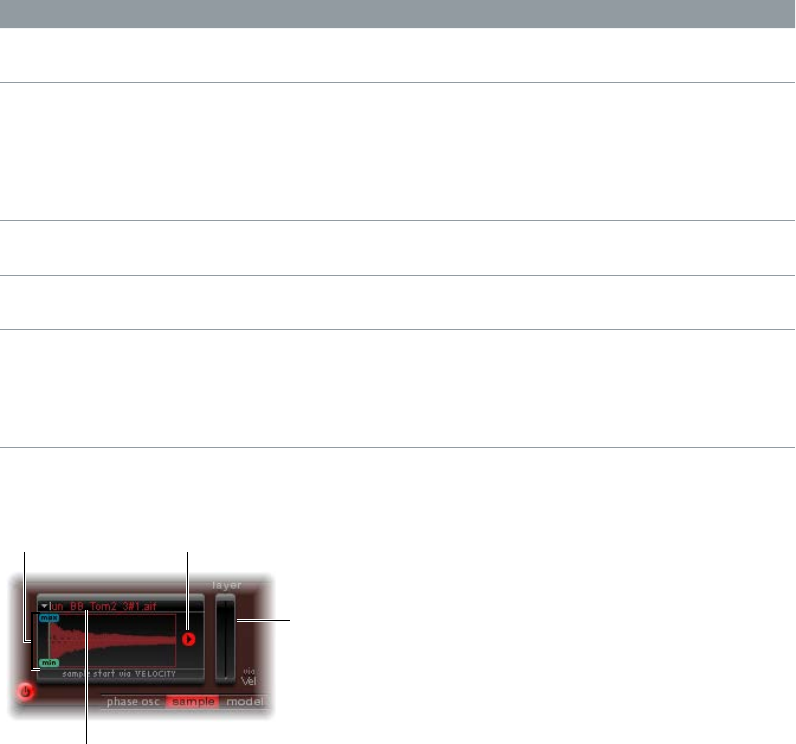
Chapter 14 Ultrabeat 345
Basic waveform characteristics
The table provides an overview of the tonal qualities of each basic waveform.
Waveform Basic tone Comments
Rectangular Nasal sounding Great for reed instruments, synth
blips, basses
Square Hollow and woody sounding Useful for basses, clarinets,
and oboes. The pulse width
of (oscillator 2 and 3) square
waveforms can be smoothly scaled
between 50% and the thinnest of
pulses.
Sawtooth Warm and even Useful for strings, pads, bass, and
brass sounds
Triangle Sweet sounding, softer than
sawtooth
Useful for utes, pads
Sine A pure tone The sine wave of oscillator 1
can be frequency-modulated by
oscillator 2. This kind of frequency
modulation forms the basis of
FM synthesis.
Use Ultrabeat oscillator 2 sample mode
In sample mode, oscillator 2 uses an audio le as a sound source.
Max and Min sliders Playback Direction button
Layer sliders
Sample Name display
Sample mode parameters
•Sample Name display: Use to load and unload samples or to display the loaded sample in the
Finder. Click the arrow in the upper-left corner of the waveform display to open.
•Max/Min sliders: Move to set the start point of the sample—depending on the dynamics
(incoming velocity level) of the performance.
•Min: Determines the start point of the sample at the minimum velocity level (velocity = 1).
•Max: Determines the start point of the sample at the maximum velocity level (velocity = 127).
Note: If Min and Max are set to the same value, velocity has no eect on the sample
start point.
•Playback Direction button: Changes the playback direction of the sample (forward or
backward).
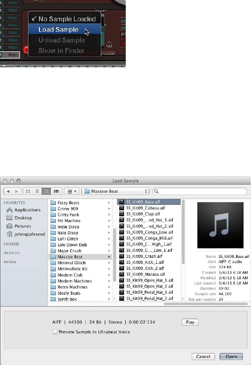
Chapter 14 Ultrabeat 346
•Layer sliders: Both factory Ultrabeat samples and sounds imported from EXS instruments often
consist of dierent layers that are dynamically switched by incoming MIDI note velocities. The
precise sample layer that incoming velocity values switch to is determined by the green Layer
slider (min), or the blue Layer slider (max).
•The green Min slider determines which layer is triggered at a MIDI note velocity = 1.
•The blue Max slider determines which layer is triggered at a MIDI note velocity = 127.
Note: If you have loaded a single sample that does not have multiple layers, the Vel Layer
slider has no eect.
Load a sample into Ultrabeat oscillator 2
Ultrabeat’s factory settings include a selection of multilayer drum and percussion samples. You
can also load your own samples in AIFF, WAV, CAF, or SDII stereo interleaved format.
Note: The velocity layering function is not available for user-loaded samples.
1 Choose Load Sample from the pop-up menu in the upper-left corner of the waveform display.
2 In the Load Sample window, browse to the audio le you want to use, and do one of the
following:
•To load the chosen le into oscillator 2, click Open.
•To retain the current state, click Cancel.
Use Ultrabeat’s load sample preview
You can audition samples before importing them into Ultrabeat.
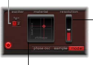
Chapter 14 Ultrabeat 347
Do one of the following:
mTo preview audio les (AIFF, WAV, SD2, CAF, UBS) before loading, click the Play button. Click the
button again to stop playback.
Clicking the Play button loops playback of the currently selected sample le. The sample
is played with no manipulation: all lters, EQ, envelopes, and other synthesizer parameters
are ignored.
mTo audition multiple les, click Play once, then step through the les by pressing the Up Arrow
and Down Arrow keys or by clicking each lename.
Note: Independent auditioning of all layers is not possible. In multilayer UBS les, the audition
function plays the sample at a xed velocity of 75%. Only the layer addressed by this velocity
value is played.
mTo temporarily replace the sample les of the currently selected drum sound, click the “Preview
Sample in Ultrabeat Voice” checkbox.
The drum sound can be triggered as usual (played notes, MIDI region events, or Ultrabeat
sequencer events) while the Load Sample window is open and dierent les are being
selected. The selected sample can be heard as part of the current drum sound, inclusive of all
synthesizer processing.
Important: Any eects inserted into the Ultrabeat instrument channel strip are heard when you
preview samples.
Use Ultrabeat oscillator 2 model mode
This oscillator 2 mode employs a method of synthesis known as component modeling. This tone
generation technique mimics the physical properties of an object, such as a guitar string. Further
objects are used to stimulate the string, emulating the way that it is played: plucked, bowed, and
so on. Although the term string is used, model mode enables you to create sounds that don’t
sound like traditional stringed instruments.
The string is the element that is responsible for the basic tone. Ultrabeat oers parameters that
enable you to adjust its material—what it’s made of, in other words.
The exciters make the string vibrate (move) in dierent ways. The string itself doesn’t make a
sound unless it is stimulated, or excited.
The signal of the vibrating string is sent to the lter, amplier, and so on, in the
Synthesizer section.
Exciter buttons
Resolution slider
Material Pad
Chapter 14 Ultrabeat 348
Model mode parameters
•Exciter buttons: Click to select one of the two contrasting exciters. Each oers dierent sound
characteristics (Type 1 and Type 2).
Note: In this context, an exciter is the agent or triggering device used to initiate the vibration
of the string. Don’t confuse it with the eect plug-in of the same name.
•Material Pad: Determines the basic tone of the string with the string Stiness and damping
(Inner Loss) parameters.
•Inner Loss: Emulates damping of the string, as caused by the string material—steel, glass,
nylon, or wood. These are frequency-dependent losses that cause the sound to become
more mellow during the decay phase.
•Stiness: Sets the rigidity of the string. In reality, this is determined by the string material
and diameter—or, to be more precise, by its geometrical moment of inertia. Stier strings
exhibit an inharmonic vibration, where overtones are not integer multiples of the base
frequency. Rather, they have higher frequencies, which can make upper or lower notes
sound somewhat out of tune with each other.
•Resolution slider: Move to determine the precision of the calculation. Higher values produce
additional harmonics. Lower values produce fewer harmonics, or inharmonic spectra.
Use Ultrabeat’s Material Pad
The combination of the Inner Loss and Stiness parameter positions determines the string
material and, therefore, the general timbre of your sound. In general synthesizer terms, use of
these parameters could be viewed as being similar to the waveform selector/generator in the
oscillator section. The default pitch of the string is C3 (middle C).
m To simultaneously adjust the Inner Loss and Stiness parameter positions, drag the ball (which
correlates to the x and y coordinates) in the Material Pad.
•Low Stiness values, combined with low Inner Loss values, lead to metallic sounds.
•Increase the Stiness to make the sound more bell-like, or glass-like. Extreme Stiness values
turn the string into a solid metal rod.
•Increase the Inner Loss value while maintaining a low Stiness level to emulate nylon or
catgut strings.
•High Stiness values, combined with high Inner Loss values, simulate wood-like materials.
Note: Option-click the ball to reset all string parameters to their default values.

Chapter 14 Ultrabeat 349
Ultrabeat ring modulator
Ring modulation is a powerful tool for the creation of inharmonic, metallic, bell-like sounds.
Ultrabeat’s ring modulator functions as an independent sound source—its signal can bypass
or be sent into the lter, independent of the oscillator 1 and 2 signals. Its volume can also
be regulated.
Important: Although the ring modulator signal is independent of the signals generated by
oscillators 1 and 2, both oscillators need to be enabled if you want to use the ring modulator
signal. Because the ring modulator is reliant on the signals of both oscillators to produce an
output signal, it is automatically muted when one of the oscillators is switched o.
The actual sound produced by the ring modulator is largely dependent on the parameter
settings of both oscillators. In particular, the tuning relationships of each oscillator have a direct
eect on the sound of the ring modulator signal. The individual levels of the oscillators, however,
have no eect on the process (or output) of ring modulation.
Level slider (The “mod”
and “via” pop-up menus
above and below the
slider enable you to
modulate the ring
modulator level.)
Ring Modulator On/Off
button
Signal Flow button
Ring modulator parameters
•Ring Modulator On/O button: Turns the ring modulator on or o.
Note: If you want to hear the ring modulator’s signal in isolation (to better judge your
settings), temporarily set the volume of both oscillators to a value of 0.
•Level slider: Move to set the output volume of the ring modulator.
•Mod and via pop-up menus: Choose the modulation source (and optional via source) for the
Level parameter. When either source is active, small sliders (handles) appear on either side of
the Level slider. See Ultrabeat modulation overview on page 360.
•Signal Flow button: Determines the routing of the ring modulator signal. It is sent either to the
lter (the Signal Flow button turns red), or directly to the EQ section (the Signal Flow button
remains gray). The direction of the arrow on the Signal Flow button illustrates the routing.
Note: The Signal Flow button determines how the ring modulator output signal is routed. It
doesn’t turn the ring modulator on or o.
Ultrabeat noise generator
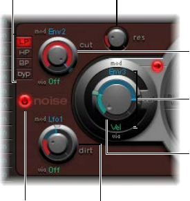
Chapter 14 Ultrabeat 350
Ultrabeat’s exible noise generator enables you to create a wide range of percussive sounds and
sound elements. The noise generator has its own lter, which functions independently of the
main Ultrabeat lter, although the noise generator lter can also be used on the overall sound.
Technically, a noise signal contains all tonal frequencies, at a roughly equal volume level. As
all frequencies in the spectrum are audible, it makes it dicult for human beings to hear any
tonality (pitch) in a noise signal. Despite this, or as a direct result of it, noise is an indispensable
ingredient when creating drum sounds.
Filter Type buttons
On/off button
Cutoff knob and “mod”
and “via” menus
Volume knob
Dirt knob and “mod” and
“via” menus
Res(onance) knob
Mod and “via” menus
(for volume)
Noise generator parameters
•On/O button: Turns the noise generator on or o. When programming a drum sound, you
can turn the individual sound sources on or o. You can also listen to, or remove, individual
components of the sound separately in this way.
•Filter Type buttons: Switch the noise generator’s integrated lter between lowpass, highpass,
and bandpass lter types.
•LP (lowpass): This lter type allows frequencies that fall below the cuto frequency to pass.
The lter slope is xed at 12 dB/octave.
•HP (highpass): This lter type allows frequencies above the cuto frequency to pass. The lter
slope is xed at 12 dB/octave.
•BP (bandpass): The frequency band directly surrounding the center frequency (determined
with the Cuto knob) is allowed to pass. All other frequencies are cut. The Resonance
parameter controls the width of the frequency band. The bandpass lter is a two-pole lter
with a slope of 6 dB/octave on each side of the center frequency of the band.
•byp (bypass): Disables the integrated lter.
•Cut(o) and Res(onance) knobs: Rotate to set the cuto/center frequency and resonance/
bandwidth behavior of the integrated lter.
•The Cut knob denes the point in the frequency spectrum where the signal is boosted or
cut. Depending on the selected lter type, you can make a sound darker (LP), thinner (HP), or
more nasal (BP) by adjusting the Cut value. Cuto can be modulated by sources in the mod
and via pop-up menus.
•Increasing resonance boosts frequencies that surround the cuto frequency. Values range
from 0 (no increase) to self-oscillation of the lter at high resonance values. Self-oscillation
is typical of analog lter circuits. It occurs when the lter feeds back into itself and begins to
oscillate at its natural frequency when high resonance values are used.

Chapter 14 Ultrabeat 351
•Dirt knob: This parameter was specically developed for the noise generator. Higher values
alter the white noise signal, making it more grainy. The Dirt parameter is particularly
eective at high resonance values. Dirt can be modulated by sources in the mod and via
pop-up menus.
•Volume knob: Rotate to set the output level of the noise generator. Volume can be modulated
by sources in the mod and via pop-up menus.
•Signal Flow button: Determines whether the noise generator signal is routed through the main
Ultrabeat lter, or directly to the EQ (Output) section. When turned on, the button is lit and an
arrow indicates the direction of the signal ow.
Note: The Signal Flow button has no eect on the independent lter within the noise
generator. The independent lter is deactivated with the “byp” button. It is therefore
possible to lter the noise generator signal twice. In some instances you may want the noise
generator signal to bypass the main lter, thus freeing the main lter for other drum sound
processing duties.
Use Ultrabeat’s lter section
Ultrabeat provides a powerful multimode lter that can dramatically, or subtly, alter the timbre of
your drum sounds.
Cutoff knob Filter on/off button
Resonance knob
Mod and “via” menus
Filter type and slope
buttons
Filter parameters
•Filter (On/O) button: Turns the entire Filter section on or o. Deactivating the Filter section
makes it easier to hear adjustments to other sound parameters, as the lter always heavily
aects the sound. If the Filter label is red, the lter is engaged. If gray, the lter is disabled.
•Filter Type buttons: Switch the lter between lowpass, highpass, bandpass, or band-rejection
lter types.
•Filter Slope buttons (12 and 24): Switch the lter between dierent slopes.
•Cut(o) and Res(onance) knobs: Rotate to set the cuto/center frequency and resonance/
bandwidth of the lter.
•mod and via pop-up menus: Choose the modulation source (and via source) for the Cuto and
Resonance parameters. See Mod and via modulations in Ultrabeat on page 360.
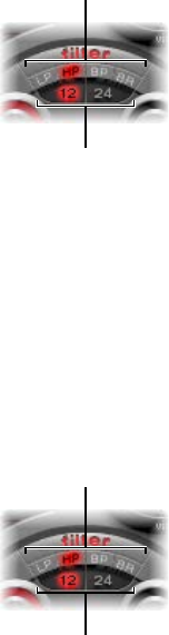
Chapter 14 Ultrabeat 352
Set Ultrabeat’s lter type
Ultrabeat’s lter can operate in several modes, allowing specic frequency bands to be ltered
(cut away) or emphasized.
mTo select a lter type, click one of the following buttons:
•LP (lowpass): This lter type allows frequencies that fall below the cuto frequency to pass.
When set to LP, the lter operates as a lowpass lter. The slope of the lter can be set to 12 or
24 dB/octave in LP mode.
•HP (highpass): This lter type allows frequencies above the cuto frequency to pass. When set
to HP, the lter operates as a highpass lter. The slope of the lter can be set to 12 or 24 dB/
octave in HP mode.
•BP (bandpass): The frequency band directly surrounding the center frequency (set with the
Cuto knob) is allowed to pass. All other frequencies are cut. The Resonance parameter
controls the width of the frequency band. The bandpass lter is a two-pole lter with a slope
of 6 or 12 dB/octave on each side of the center frequency of the band.
•BR (band rejection): The frequency band directly surrounding the center frequency (set with
the Cuto knob) is rejected, while the frequencies outside this band can pass. The Resonance
parameter controls the width of the rejected frequency band.
Filter type buttons
Filter slope buttons
Set Ultrabeat’s lter slope
Most lters don’t completely suppress the portion of the signal that falls outside the frequency
range dened by the Cuto parameter. Frequencies that are located close to the cuto frequency
are generally reduced less than those that are farther away. The higher the slope value, the more
apparent the level dierence is between frequencies that are near to the Cuto frequency and
those that are farther away from it.
mClick the 12 dB or 24 dB button. The slope (curve) chosen for the Filter expresses the amount
of rejection in decibels per octave. The steeper the slope, the more severely the level of signals
below the cuto frequency is aected in each octave.
Filter type buttons
Filter slope buttons

Chapter 14 Ultrabeat 353
Use Ultrabeat’s lter Cuto parameter
mRotate the Cuto Frequency (Cut) parameter to control the brilliance or determine the center
frequency of the signal.
•In a lowpass lter, the higher the cuto frequency is set, the higher the frequencies of signals
that are allowed to pass.
•In a highpass lter, the cuto frequency determines the point where lower frequencies are
suppressed, with only upper frequencies allowed to pass.
•In a bandpass/band-rejection lter, the cuto frequency determines the center frequency for
the bandpass or band-rejection lter.
Use Ultrabeat’s lter Resonance parameter
mRotate the Resonance (Res) parameter to emphasize or suppress portions of the signal above or
below the dened cuto frequency, or to determine the width of the band that surrounds the
cuto frequency.
•In a lowpass lter, Resonance emphasizes or suppresses signals below the cuto frequency.
•In a highpass lter, Resonance emphasizes or suppresses signals above the cuto frequency.
•In bandpass/band-rejection lters, resonance determines the width of the frequency band
that surrounds the center frequency (set with the Cuto Frequency parameter).
Set the signal ow order through Ultrabeat’s lter and distortion unit
The output signals of both oscillators, the ring modulator, and the noise generator are sent to
Ultrabeat’s central Filter section (if not bypassed with the various Signal Flow buttons). The Filter
section oers a multimode lter and a distortion unit.
mClick the arrow to change the signal ow order between the following:
•First the Distortion unit, then the Filter circuit (arrow pointing up)
•First the Filter circuit, then the Distortion unit (arrow pointing down).
Distortion unit
Sounds are passed
through the filter and
distortion unit as
determined by the
direction of the arrow
found at the equator of
the filter section.
Multimode filter
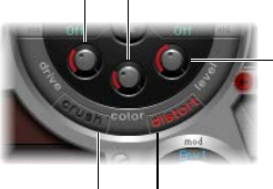
Chapter 14 Ultrabeat 354
Ultrabeat distortion circuit
The Distortion circuit provides either a bit crusher or distortion eect.
The bit crusher reduces the digital resolution of the sound, measured in bits, achieving an
intentionally digital coloration of the sound. The distortion eect is modeled on an analog
distortion unit, which distorts the sound by overdriving the level.
Both methods lead to distortions that are as tonally divergent as the two approaches. Distortion
oers a more analog tone while the bit crusher sounds unmistakably digital.
Note: The arrow in the Filter section determines whether the Distortion circuit is inserted
before or after the multimode lter (see Set the signal ow order through Ultrabeat’s lter and
distortion unit on page 353).
Drive knob Color knob
Crush button Distort button
Level knob
Distortion parameters
•Crush and Distort buttons: Activate the mode you want to use. The name of the active eect
type is indicated in red. If neither button is active, the Distortion circuit is bypassed.
•Drive knob: Controls the amount of distortion.
•Color knob: Determines the basic tone of the distortion. Higher values result in a brighter
sound. Lower values lead to a darker, warmer tone.
•Level knob: Sets the output level of the Distortion eect when in Distortion mode. In Bit
Crusher mode, this knob sets a threshold level for incoming signals from the sound sources
that must be reached before distortion (bit crushing) begins.

Chapter 14 Ultrabeat 355
Ultrabeat Output section
Ultrabeat Output section overview
Depending on the status of each Signal Flow button, the output signals of both oscillators, the
ring modulator, and the noise generator are routed to the Output section of Ultrabeat. This
routing is either direct or through the Filter and Distortion section.
The Output section passes signals through both equalizers (EQ), then on to the Pan Modulation/
Stereo Spread section (in a precongured order) before the nal level is set for the selected
sound and the trigger behavior is adjusted.
Pan modulation
Voice volume
Trigger mode controls
Two-band EQ
•Two-band EQ: Provides precise tonal control of each drum sound.
•Pan Modulation and Stereo Spread parameters: Pan Modulation varies the panorama position of
a drum sound. Stereo Spread broadens the stereo image.
•Voice volume: Sets the default level of each drum sound.
•Trigger Mode controls: Determine the way that Ultrabeat reacts to incoming MIDI notes. This is
independently dened for each sound.
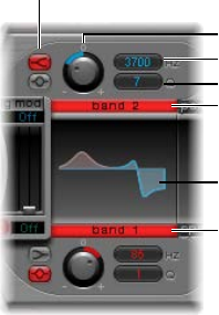
Chapter 14 Ultrabeat 356
Adjust Ultrabeat’s two-band EQ
Both equalizer bands have almost identical features. You can adjust each band separately.
EQ type buttons
EQ curve display
Q field
Frequency field
Gain knob
Band 2 button
Band 1 button
Two-band EQ parameters
•Band 1 and Band 2 buttons: Click to turn each band on or o. When active, the label is red. If
neither EQ is activated, the signal passes through unaected. Band 1 is a low shelving EQ.
Band 2 is a high shelving EQ.
•EQ type buttons: Switch between two dierent types of EQs: shelving (top button) and peak
(lower button).
•In shelving mode, all frequencies above or below the set frequency are either increased
or reduced.
•In peak mode, only frequencies located near the set frequency are aected.
Note: Shelving EQs behave much like synthesizer lowpass and highpass lters. The key
dierence is that lowpass and highpass lters merely dampen certain frequencies (lter them
out), whereas shelving EQs also allow these frequencies to be boosted.
•Gain knobs: Positive values boost a certain frequency range as determined by the EQ type and
Hz settings. Negative gain values reduce the gain of the frequency range. If the Gain knob is
set to a value of 0, the EQ has no eect. Option-click a Gain knob (or click the 0 above the Gain
knob) to set it to a neutral position.
•Frequency (Hz) eld: Drag vertically to set the frequency range to be boosted or reduced.
Option-click the parameter to set the value to a neutral position: this is 200 Hz for band 1, and
2000 Hz for band 2.
•Q eld: Drag vertically to set the Q (quality) factor. The eect of Q on the sound depends on
the selected EQ type:
•Shelving lters selected: as the Q value increases, the area around the threshold frequency
becomes more pronounced.
•Peak EQ selected: Q determines the width of the frequency band selection, low Q values
select a broad band, and high Q values select a very narrow band to be boosted or reduced
with the Gain knobs.
Each EQ band displays parameter changes on a frequency response curve. The display provides
access to the Gain, Hz, and Q parameters of each band.
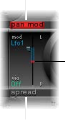
Chapter 14 Ultrabeat 357
Edit the graphical EQ curve
Do any of the following:
mTo change the EQ frequency, drag horizontally.
mTo change the Gain, drag vertically.
mTo change the Q factor, drag the handle shown at the peak (maximum point) of the EQ curve.
Ultrabeat pan and stereo spread
Ultrabeat pan modulation mode
The EQ’s output signal is passed along to the Pan Modulation/Stereo Spread section where the
placement of the sound in the stereo eld can be modulated (pan modulation mode), or the
stereo basis of the sound can be broadened (stereo spread mode).
Pan Modulation varies the panorama position of a drum sound with a mod (and via) source.
Note: The modulation set here is relative to the panorama position set in Ultrabeat’s mixer in the
Assignment section.
The panorama position
(set in the mixer) is
represented by a thin,
red line.
Pan Mod button
Spread button
Pan modulation parameters
•Pan Mod button: Click to turn on pan modulation mode. If neither mode is activated, the signal
passes through unaected.
•Mod and via pop-up menus: Choose the modulation and via sources for pan modulation.
•Mod and via sliders: The blue and the green controls set the amount (intensity) of mod and
via modulation.
Note: You cannot directly move the red line that represents pan position shown in this section.
To move the line, rotate the Pan knob in the Mixer section.
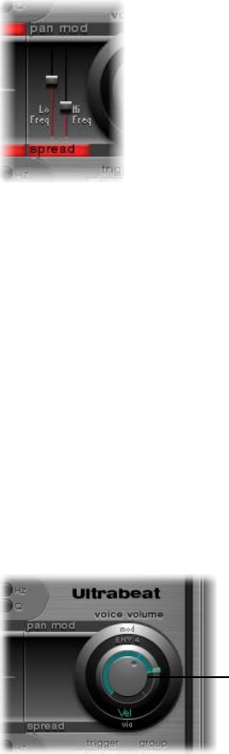
Chapter 14 Ultrabeat 358
Ultrabeat stereo spread mode
The EQ’s output signal is passed along to the Pan Modulation/Stereo Spread section where the
placement of the sound in the stereo eld can be modulated (pan modulation mode), or the
stereo basis of the sound can be broadened (stereo spread mode).
Stereo Spread broadens the stereo image, making it wider and more spacious.
Stereo spread parameters
•Spread button: Click to turn on stereo spread mode. If neither mode is activated, the signal
passes through unaected.
•Lo Freq(uency) slider: Move to set the width (the spreading eect) of bass frequencies: the
higher the value, the more prominent the eect becomes.
•Hi Freq(uency) slider: Move to set the width of high frequencies.
Ultrabeat voice volume control
The Voice volume knob adjusts the output volume of individual drum sounds. To be more exact,
when you adjust the Voice volume knob, you set the maximum level for the selected drum
sound with Envelope 4, following the attack phase of Envelope 4.
Note: Envelope 4 (Env 4) is hard-wired to level control for the selected sound. Each sound in the
kit also has a further three envelopes and other modulation sources available for control of other
synthesis parameters.
Voice volume knob
The intensity of Envelope 4’s impact on Voice volume can also be modulated with a via source.
Note: Voice volume precedes the level sliders in the mixer. This approach allows the starting
volume of individual drum sounds to be set independently of their relative levels in the
drum kit mix, which you change in the Assignment section’s mixer. See Ultrabeat Assignment
section overview.

Chapter 14 Ultrabeat 359
Change Ultrabeat’s trigger mode
The way Ultrabeat reacts to a succession of incoming notes is set independently for each sound.
Parameters that provide control over this aspect of Ultrabeat’s behavior are found in the trigger
mode section.
Trigger pop-up menu
Group pop-up menu
Gate button
Trigger mode parameters
•Trigger pop-up menu: Choose either Single or Multi trigger mode.
•Single: A new trigger note cuts o the note that is currently playing.
•Multi: When a new note is played, currently playing notes continue to decay in accordance
with their respective amplitude envelope settings (Env 4).
•Group pop-up menu: Choose between O and settings 1 through 8. If two dierent sounds are
assigned to the same group, they cut each other o when a new note message is received.
Only one sound in the group can be played at a time.
A typical use of this feature is when programming hi-hat sounds: when playing a real hi-hat,
the closed hi-hat note cuts o or mutes the ringing of the open hi-hat. This feature is often
referred to as “hi-hat mode.”
Note: While in Single Trigger mode, only the currently sounding note of the same sound is cut
o. A sound that is assigned to a group cuts o all other sounds in the group, regardless of the
note played.
•Gate button: Turns the Gate function on or o. When active, the sound is immediately cut o
when the MIDI note is released (MIDI note o), regardless of envelope settings.
Note: The Gate function ensures that a specic sound does not play—it can’t be heard—after
a note-o event sent from the host or Ultrabeat’s internal sequencer. Note length can be an
important creative element when programming rhythm tracks.
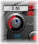
Chapter 14 Ultrabeat 360
Ultrabeat modulation
Ultrabeat modulation overview
Most sound parameters can be controlled dynamically (modulated) in Ultrabeat. Ultrabeat
provides two LFOs, four envelope generators, velocity, and four user-denable MIDI controllers as
modulation sources.
Ultrabeat’s modulation routings feature three key elements:
•The modulation target: The synthesizer parameter that you want to modulate.
•The modulation source: The parameter that modulates the target.
•The via source: A secondary modulation source that can inuence the intensity of the rst
modulation source.
Note: You can use the same sources and the same via controllers in multiple
modulation routings.
Mod and via modulations in Ultrabeat
You can modulate a sound parameter using an adjustable value—the modulation depth
or intensity—with the mod parameter. You can choose between two LFOs, four envelope
generators, and Max as sources for this modulation.
Via inuences the modulation eect as follows. The depth of the rst modulation (mod) can be
modulated by a separate, independent source. The intensity of this secondary modulation is set
with the via parameter. The sources for via modulations include velocity and four user-denable
MIDI controllers.
A typical via modulation usage would be to increase a pitch sweep as you play at higher
velocities. The harder a key is played, the higher in pitch it sounds—which is ideal for synthesized
tom-tom sounds, for example. To create this routing, you would use an envelope (Env) as the
mod source for oscillator pitch, and Velocity (Vel) as the via source.
Consider the following example:
The default Cut (Cuto) parameter value is 0.50. No modulation source has been chosen in either
the (blue) mod or (green) via pop-up menu. Both are O in the image below.
When a modulation source is chosen from the mod pop-up menu (Env 1 in the image below),
the ring around the knob is turned on. Drag in the ring to set a value (0.70 in the example) for
the Cut parameter—when aected by the mod source.
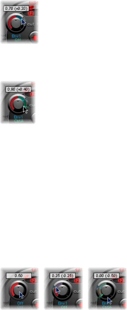
Chapter 14 Ultrabeat 361
Note: Exact values are shown in the help tags when adjusting parameters.
As soon as a modulation source is chosen from the via pop-up menu (Ctrl A in the image below),
a movable slider appears on the mod ring. Drag this slider to set the maximum modulation value
that can be reached through use of the via source (0.90 in this example).
The mod and via controls indicate the minimum and maximum values that the modulated
parameter can attain, in comparison to the default value.
In the example, the Cut(o) frequency of the lter is set to a default value of 0.50. The mod
source (Env 1) drives the Cut value up from 0.50 to 0.70 during the sound’s attack phase and
back down to 0.50 during the decay phase.
When the via source (Ctrl A) is introduced, the following occurs: when Ctrl A is at its minimum
value, nothing changes; Cuto continues to be modulated between values of 0.50 and 0.70 by
the envelope (Env 1). A maximum value for Ctrl A causes the envelope generator to vary the
parameter between the values of 0.50 (the default Cut value) and 0.90 (the via amount).
You can see the degree of maximum inuence on basic parameters by the mod and via
modulation sources—the area between the mod and via points shows the amount that the
modulation depth can be further altered by the via modulation source. In the example, the
Cuto can reach values between 0.70 and 0.90, depending on the value being sent by Ctrl A.
Another example:
Cuto is again set to 0.50, Env 1 now drives the value down to 0.25, and a maximum Ctrl A value
reduces the Cuto frequency down to 0.

Chapter 14 Ultrabeat 362
The example below illustrates the simplicity and speed of Ultrabeat’s modulation options:
In this example, the modulation intensity of Env 1, which aects Cuto, is controlled with the
dynamics of the performance (Vel). The secondary via modulation also controls its direction. Try
this setting in Ultrabeat to create some interesting sounds.
Create a modulation routing in Ultrabeat
The following applies to all parameters that oer mod (and via) modulation options.
Create a modulation routing
1 Click the mod label of the parameter you want to modulate.
2 Choose a modulation source from the mod pop-up menu.
•O: Deactivates the mod routing, and the mod control can no longer be adjusted. In this
situation, no via modulation can occur either, because via no longer has a modulation target,
and the via control disappears.
•Lfo1-Lfo2: Choose one of the LFOs (low frequency oscillators) as the modulation source.
•Env1-Env4: Choose one of the envelope generators as the modulation source.
•Max: Produces a static modulation at maximum level. When the mod value is set to Max, the
via parameter is routed directly to the modulation target. Velocity can then be used as a direct
modulation source, even though Vel is not available as a source in the mod pop-up menu.
Tip: You can also set up an external MIDI fader unit with Ctrl A, B, C, or D (see Assign Ultrabeat
MIDI controllers A–D on page 363). Use the Max menu item to route a via source—Ctrl A, B, C,
or D—to the parameter you want to control with a fader on your MIDI fader device.
3 If you want to assign a via source, choose one of the following from the via pop-up menu.
•Vel: Velocity is used as the via modulation source.
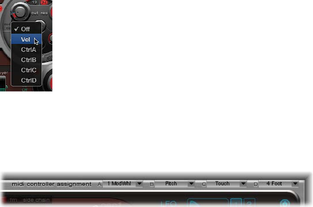
Chapter 14 Ultrabeat 363
•CtrlA to CtrlD: Choose one of these continuous controllers that can be assigned to four external
MIDI controllers. These assignments apply to all sounds in the current Ultrabeat plug-in
instance. See Assign Ultrabeat MIDI controllers A–D.
4 Adjust the mod and via controls.
Assign Ultrabeat MIDI controllers A–D
The MIDI Controller Assignments area enables you to assign any MIDI controller shown in the
menus to each of the four controller slots—Ctrl A, B, C, or D.
These assignments enable external MIDI controller hardware—such as sliders, knobs, aftertouch,
or the modulation wheel of your MIDI keyboard—to control via modulation sources in Ultrabeat.
Assign a controller
mClick the control menu (Ctrl A–D) that you want to assign, then choose the controller name or
number that you want to use.
Learn a MIDI controller assignment
1 Open the control menu (Ctrl A–D) that you want to assign, then choose the Learn menu item.
2 Move the controller on your MIDI keyboard or MIDI controller unit.
Note: If no suitable MIDI message is received within 20 seconds, the selected control reverts to
the previous value/assignment.
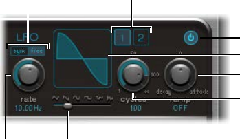
Chapter 14 Ultrabeat 364
Use Ultrabeat LFOs
Two identical LFOs are available as modulation sources in the mod pop-up menus.
The LFO (low frequency oscillator) signal is used as a modulation source. In an analog synthesizer,
the LFO frequency generally ranges between 0.1 and 20 Hz, which is outside the audible
frequency spectrum. Therefore, this type of oscillator is used only for modulation. The speed of
the LFO in Ultrabeat can reach up to 100 Hz, which aords a number of possibilities that analog
synthesizers don’t oer.
Sync and free buttons LFO 1/LFO 2 buttons
On/off button
Ramp knob
Cycles knob
Waveform display
Waveform shapeRate knob
LFO parameters
The parameters for both Ultrabeat LFOs are described below. You can adjust LFO 1 and LFO 2
independently of each other.
•LFO 1 and 2 buttons: Click to select the corresponding LFO, allowing independent parameter
adjustments for each.
•On/o button: Turn the selected LFO on or o.
•Sync/free buttons: The LFO speed (Rate) can be synchronized (Sync) to the host application
tempo or set independently (Free). Click either button to activate the corresponding mode.
•Rate knob: Rotate to set the speed of the LFO. Depending on the Sync/Free setting, the rate is
displayed in Hertz or rhythmic values—the latter when tempo synchronization is active. Rates
range from speeds of 1/64 notes to a periodic duration of 32 bars. Triplet and punctuated
values are also available.
•Waveform shape slider (and display): Drag to determine the shape of the LFO waveform.
•Cycles knob and eld: Rotate to set the number of times the LFO waveform repeats.
•Ramp knob and eld: Rotate to set the time it takes for the LFO modulation to fade in or fade
out. The Ramp value is displayed in milliseconds.
•Rotate Ramp to the right to set the LFO fade-in time.
•Rotate Ramp to the left to set the LFO fade-out time.
•At the middle position, Ramp has no eect on the LFO.

Chapter 14 Ultrabeat 365
Set Ultrabeat LFO waveforms
mDrag the Waveform Shape slider from left to right to morph the waveform from a triangle, to a
sawtooth, sine, square, and nally a rectangular wave shape—including all variations in between.
At the far right position, the LFO produces random waveforms.
The graphical display shows the current LFO waveform shape.
The table outlines how dierent waveform shapes can aect your sounds. Intermediate
waveform shapes result in hybrid waveforms and hybrid behaviors.
Waveform Comments
Triangle Well suited for vibrato eects
Sawtooth Well suited for helicopter and space gun sounds.
Intense modulations of oscillator pitch with a
sawtooth wave lead to “bubbling” sounds. Intense
sawtooth modulations of lowpass lter cuto and
resonance create rhythmic eects.
Sine Ideal for smooth, even modulations. Its position on
the Waveform Shape slider enables you to smoothly
morph between sawtooth and square/rectangular
waves.
Square and Rectangle Square/rectangular waves periodically switch the LFO
between two values. The right-hand rectangular wave
switches between a positive value and zero. The left-
hand rectangular wave switches between a positive
and a negative value set to the same amount above/
below zero.
Sample & Hold The right-hand waveform on the Waveform Shape
slider outputs random values. A random value is
selected at regular intervals, as dened by the LFO
rate. The term Sample & Hold (S & H) refers to the
procedure of taking samples from a noise signal at
regular intervals. The values of these samples are then
held until the next sample is taken.
Tip: A random modulation of oscillator pitch leads
to an eect commonly referred to as a random pitch
pattern generator or sample and hold. Try using very
high notes, at very high rates and high intensities—
you’ll recognize this well-known eect from hundreds
of science ction movies.
Chapter 14 Ultrabeat 366
Set Ultrabeat LFO waveform cycles
An LFO normally oscillates continuously. On percussive signals it can, however, be interesting to
limit the LFO cycles (repetitions of the entire waveform) to a dened number. Ultrabeat enables
you to set the number of LFO cycles with the Cycles parameter. After completing the dened
number of cycles, the LFO stops oscillating.
mRotate the Cycles knob to set the number of LFO waveform cycles. The range of Cycles parameter
values extends from 1 to 100. The Cycles parameter can also determine whether the LFO
waveform is started from the beginning, at a zero-crossing point, with each note trigger, or
continues oscillating.
•A Cycles value of 1 allows the LFO to function as an additional, very basic, envelope generator.
•Set Cycles to its maximum value (full right position) for an innite number of cycles (standard
LFO behavior). The LFO is not reset by incoming MIDI note-on messages.
•When Cycles is set to values under 100, the LFO is reset by each new MIDI note-on message
(Note On Reset).
Your choice to trigger an LFO cycle from the same spot or to allow it to oscillate freely,
regardless of phase, should be based on the needs of the sound. The random element of
free-running LFOs can make many sounds richer. This, however, can be at the expense of a
percussive attack—which is generally inappropriate for drum sounds.
Tip: Try small Cycles parameter values, with the LFO source used to control the Volume (Level) of
one or both oscillators. This results in drum ams or hand claps. You can also use minor shifts of
the LFO phase, with the Cycle value set to Innity, to add an analog character to a drum sound.

Chapter 14 Ultrabeat 367
Ultrabeat envelope overview
Ultrabeat features four identically specied envelope generators per voice. They are abbreviated
as Env 1 to Env 4. In addition to potential use as a modulation source (in the mod pop-up menus
of various sound parameters), Env 4 is permanently connected to the Voice Volume parameter. In
other words, each Ultrabeat drum sound has a hard-wired volume envelope generator—Env 4.
See Attack, decay, sustain, and release on page 487 for information on the roots of the term
envelope generator and its basic function.
The default behavior of the envelope generators is known as the one-shot envelope mode: after
a key is pressed (note-on message), the envelopes run their course, regardless of how long the
note is held. This setting is ideal for percussive signals, because it emulates the natural behavior
of acoustic percussion instruments.
For special cases, such as sustained pad or cymbal sounds, you can activate a sustain mode
where the envelopes take the lengths of the played notes into account.
Ultrabeat’s envelope display provides a unique envelope design, consisting of Bezier curves in
which two segments—attack and decay—constitute the entire envelope.
Attack time handle Decay time handle
Decay curve handle
Decay curve handle
Attack curve handle Attack curve handle
In the envelope graphic, you can see various handles (junction points) of two dierent sizes. Drag
these handles to adjust the envelope shape.
Both of the larger handles on the x-axis (the horizontal, or time axis, at the bottom) control the
attack and decay times, respectively. A vertical line extends up from the rst of the two handles
(attack), and divides the envelope into an attack and decay phase.
Both segments have two small curve handles. You can drag these in any direction to deform the
contour of the envelope and shape its amplitude.
You can also directly drag anywhere on the curve itself to reshape the envelope.
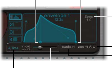
Chapter 14 Ultrabeat 368
Ultrabeat envelope parameters
To edit envelope parameters, you rst need to select one of the four envelopes with the 1-4
buttons. The parameters of the corresponding envelope can then be changed in the envelope
display window.
1–4 buttons
Zoom scroll
Zoom buttons
Decay time handle
Sustain button
Mod (via vel) slider
Env mod menu
Attack time handle
Envelope parameters
•Buttons 1–4: Click to select one of the four envelopes. Only the selected envelope can be
edited. The button frame of the chosen envelope is highlighted, and the envelope display
immediately updates to reect your selection.
•Attack time handle: Drag to set the time it takes for the envelope to reach its maximum value
after receiving a note-on message. This period is called the attack phase.
•Decay time handle: Drag to set the time it takes for the envelope to fall to an amplitude of zero,
after it has reached its maximum value (dened in the attack phase).
•Zoom scroll eld: Drag horizontally to resize the visible contents of the envelope display.
•Env mod pop-up menu: Choose the modulation target (either the time or shape of the
envelope attack or decay phase) by velocity. Choices are A Time, A Shape, D Time, and D Shape.
•Mod (via vel) slider: Drag to set the intensity of velocity modulation (of the target specied in
the Env mod pop-up menu).
•When you modulate Shape, low velocity values make the envelope concave. Higher values
make the envelope convex.
•When you modulate Time, high velocity values reduce the length of the envelope segment.
Lower velocity values increase the length of the envelope segment.
•Sustain button: Click to turn on and display a red handle (and vertical line) on the x-axis. This
handle can be dragged horizontally, but only within the envelope decay phase. The amplitude
that the envelope reaches at the Sustain junction point is retained until the MIDI note
is released.
Note: If the Sustain button is not turned on, the envelope functions in one-shot mode, and
the note length (MIDI note-o command) is disregarded.
•Zoom (to t) button: Click to enlarge the envelope to ll the entire width of the envelope
display. This makes it easier to adjust junction points and curves.
Note: When the Zoom function is turned on, the decay handle can be dragged beyond the
right edge of the envelope display area, enabling you to lengthen the decay time. After you
release the mouse button, the envelope graphic is automatically resized to t the display area.
•Zoom A/D buttons: Click to show only the attack (A) or decay (D) phase across the entire width
of the envelope display. This enables you to perform more accurate edits to envelope shapes
(down to millisecond values).
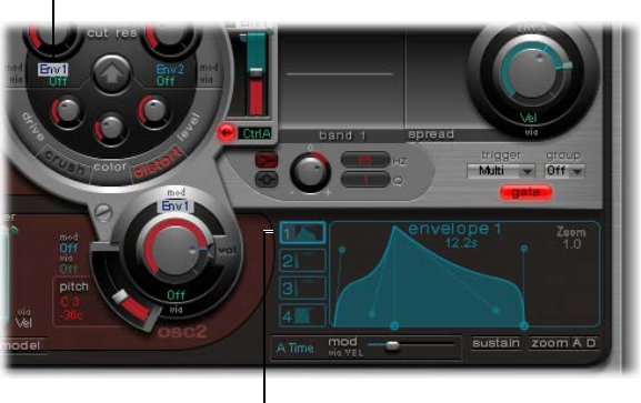
Chapter 14 Ultrabeat 369
Use Ultrabeat’s modulation target display
Ultrabeat has a feature that makes it easy to nd the modulation targets of LFOs and envelopes.
Find modulation targets of LFOs and envelopes
mClick the numerical eld of the modulation source to highlight all of its modulation targets.
Highlighted modulation
target of Envelope 1
Click here to highlight
all modulation targets of
Envelope 1.
Chapter 14 Ultrabeat 370
Ultrabeat step sequencer
Ultrabeat step sequencer overview
Ultrabeat incorporates a powerful, integrated step sequencer, which you can use to create
polyphonic rhythmic sequences and patterns. The sequencer displays running light-style controls
like those of classic drum machines and shares many of the sequence and pattern creation
methods employed in these devices.
Ultrabeat’s step sequencer expands on the features of hardware drum machines by providing
extensive automation and editing features. These enable you to precisely vary the timbre of
the sound and the overall dynamics at any point in the pattern. The step sequencer plays an
important role in shaping the rhythms and sounds that you can produce with Ultrabeat.
The step sequencer allows all Ultrabeat sounds to be combined in patterns, based on sequences
for each individual sound. Its design and use—commonly referred to as step programming—are
based on analog sequencers and drum machines. Unlike these analog precursors, Ultrabeat
enables you to program automated changes for nearly every synthesizer parameter.
If you’re unfamiliar with the concept of step sequencing, see Step sequencer basics.
Step sequencer basics
The fundamental idea behind analog step sequencers is to set up a progression of control
voltages and output these step by step, typically in an endlessly repeating pattern. This principle
helped to spawn a number of electronic music styles based on the mesmerizing eect that
repeating patterns can have.
In early analog sequencers, three control voltages were usually created per step to drive dierent
parameters. The most common usage was control of a sound’s pitch, amplitude, and timbre
(cuto) per step.
The control surface of analog sequencers often contained three rows of knobs or switches
aligned on top of (or beside) each other. Each row commonly contained 8 or 16 steps. Each
row provided a control voltage output that was connected to a control input (for a particular
parameter) on a synthesizer. A trigger pulse determined the tempo between steps. A running
light (an LED) indicated the step that was currently being triggered.
The running light programming concept also appeared in later drum computers, the most well-
known examples being the Roland TR series drum machines.
The introduction of the MIDI standard and increased use of personal computers for music
creation led to a rapid decline in the step sequencer and related technology. More exible
recording and arranging concepts that didn’t adhere to the step and pattern principle were
possible with the far more powerful personal computer.
Despite these technological advances, step sequencers haven’t disappeared completely.
Hardware groove boxes have experienced a renaissance in recent years due to their intuitive
nature, which has made them a favored tool for rhythm programming.
Ultrabeat’s integrated step sequencer couples the advantages and general working principles of
its analog forebears with signicantly more exible control options, making it a powerful tool for
rhythm creation.
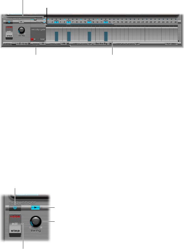
Chapter 14 Ultrabeat 371
Ultrabeat step sequencer interface
Ultrabeat’s step sequencer contains a sequence for each sound in a drum kit. Each sequence can
consist of up to 32 steps.
A pattern is a container for all sequences in a drum kit. Up to 24 patterns can be saved and
recalled with each Ultrabeat setting.
Pattern parameters Step grid
Pattern parameters
Global parameters
The step sequencer is divided into three sections.
•Global parameters: Turn the step sequencer on or o, control playback, provide access to
various modes, and control the overall playback feel. See Ultrabeat global sequencer controls.
•Pattern parameters: Provide control over the length and resolution of the currently selected
pattern. You can also accentuate individual steps in the pattern—for each drum sound. See
Ultrabeat pattern controls.
•Step grid: This is where actual sequencing takes place. A sequence of up to 32 steps, for the
sound that is currently selected in the Assignment section, is shown. You can add, remove, or
alter events in the grid. See Ultrabeat Step grid overview.
Note: An alternate view allows you to simultaneously see and edit the steps of all drum sounds
in the pattern. See Ultrabeat Step grid full view on page 377.
Ultrabeat global sequencer controls
The following parameters apply globally to all patterns.
On/off button
Transport button
Swing knob
Edit Mode switch
Global sequencer parameters
•On/O button: Turns the step sequencer on or o.
•Edit Mode switch: Select either Voice or Step mode.
•Voice mode (default): In Voice mode, editing a drum sound’s parameters changes the drum
sound itself.
•Step mode: In Step mode, you can automate a sound’s parameters from one step to the next.
See Ultrabeat step automation overview on page 378.
•Transport button: Starts and stops the sequencer pattern. The step sequencer is always
synchronized to the host application tempo.
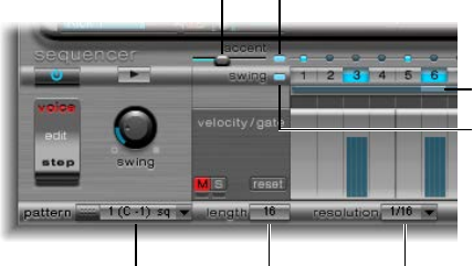
Chapter 14 Ultrabeat 372
Note: If the Transport button is blue, the step sequencer interprets incoming MIDI notes
between C-1 and B0 as performance information. See MIDI control of Ultrabeat’s step
sequencer on page 381.
•Swing knob: Rotate to set the swing intensity for all sounds that have the Swing function
turned on. See Use Ultrabeat’s swing function on page 373.
Ultrabeat pattern controls
A pattern contains all events, stored in sequences, for all 25 sounds. You can select one of 24
patterns and set parameters that globally aect all sounds in the kit.
Length bar
Pattern menu Length field
Swing Enable button
Accent slider Accent on/off button
Resolution menu
Pattern parameters
•Pattern pop-up menu: Click to choose one of the 24 patterns.
•Length eld and bar: You can adjust the length of the grid (and therefore the pattern) by
dragging the value in the Length parameter eld or the bar beneath the swing buttons.
•Resolution pop-up menu: Click to choose the resolution of the pattern. Resolution denes the
metric unit of a measure that is represented by the individual steps. For example, the 1/8
setting means that each step of the grid represents an eighth note. Given a pattern length of
32 steps, the pattern would run for 4 measures (the 32 setting applies to the entire grid and,
therefore, all sounds).
Note: The interplay between Length and Resolution values enables you to create dierent
time signatures. For example, a Length value of 14 and a Resolution of 1/16 results in 7/8
time; a Length of 12 and a Resolution of 1/16 results in 3/4 time; and a Length of 20 and a
Resolution of 1/16 results in 5/4 time.
•Accent button and slider: Allows individual steps to be strongly emphasized, or accentuated.
See Set Ultrabeat step sequencer accents on page 377.
•Swing Enable button: When turned on, the grid of the currently selected sound is played in
accordance with the Swing knob setting. See Use Ultrabeat’s swing function on page 373.
You can reorganize the 24 patterns in the Pattern pop-up menu, using Copy and
Paste commands.
Copy a pattern using a shortcut menu
1 Choose the pattern that you want to copy from the Pattern pop-up menu.
2 Control-click (or right-click) the Pattern pop-up menu, and choose Copy from the shortcut menu.
3 Choose the target pattern from the Pattern pop-up menu.
4 Control-click the Pattern pop-up menu, and choose Paste from the shortcut menu.
Chapter 14 Ultrabeat 373
Copy a pattern using the key command
You can also use a key command to copy patterns.
1 Choose the pattern that you want to copy in the Pattern pop-up menu.
2 Press Option, open the Pattern pop-up menu, and choose another Ultrabeat pattern.
The pattern in the target position is replaced with this one.
Note: All existing sequencer data in the target pattern is replaced. If you change your mind
during the process, choose the source pattern number.
Clear a pattern
1 Choose the pattern that you want to clear in the Pattern menu.
2 Control-click (or right-click) the Pattern pop-up menu, and choose Clear from the shortcut menu.
Use Ultrabeat’s swing function
Swing changes the distance between notes. Only even-numbered steps are aected by the
Swing parameter, with notes on odd-numbered steps remaining where they are.
Which beats are aected depends on the selected Resolution parameter setting, as illustrated in
the following example: At a Resolution of 1/8 and a Length of 8, the notes on steps 1, 3, 5, and 7
represent quarter notes in the measure. These remain unchanged. Only the eighth notes found
between them (steps 2, 4, and so on) are shifted by the Swing function. The amount of shift is
equal to the swing intensity (set with the Swing knob).
Note: Swing is active only for grid resolutions of 1/8 and 1/16. See Ultrabeat pattern controls on
page 372.
Use the swing function
1 Click the Swing Enable button.
This forces the grid of the currently selected sound to be played in accordance with the Swing
knob setting.
2 Adjust the Swing knob.
At a zero setting (full left position), the Swing function is disabled. Rotate the knob to the right to
move aected notes toward the following note.
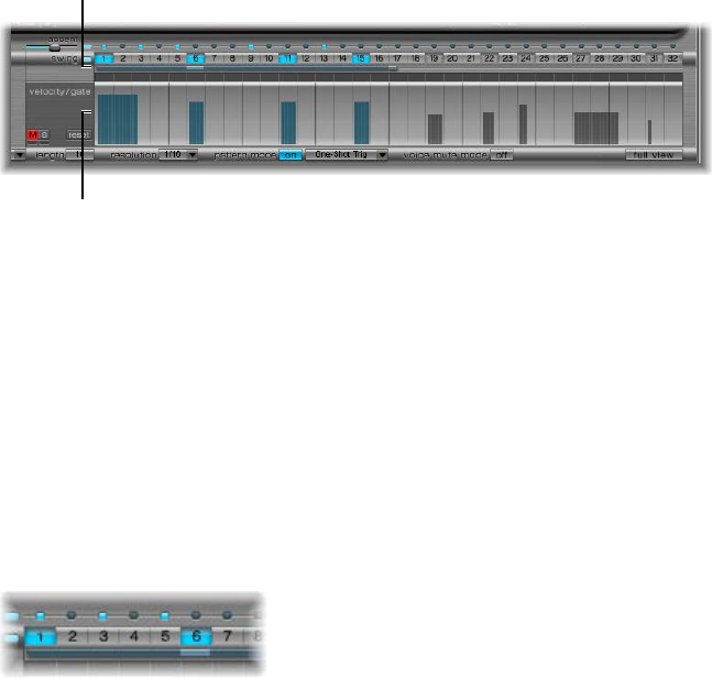
Chapter 14 Ultrabeat 374
Ultrabeat Step grid
Ultrabeat Step grid overview
The Step grid displays sequence steps on two rows. The steps shown in these rows correspond to
the sound that is currently selected in the Assignment area. Choosing a dierent sound switches
the sequencer display to show the rows that correspond to the newly selected sound.
The Step grid area contains two rows, each with 32 elds (steps).
Trigger row
Velocity/Gate row
•Trigger row: Click a button to activate or deactivate the sound on the corresponding beat.
•Velocity/Gate row: Sets the length (gate time) and velocity of steps entered in the Trigger row.
Both parameters are displayed as a single graphical bar.
•The bar’s height represents the velocity.
•The bar’s length, from left to right, indicates the note length.
Create and remove steps
The Trigger row consists of buttons 1 through 32, which represent steps or beats in the selected
sequence. Note trigger events are placed on corresponding steps. This is where you designate
when (on which beat) the selected sound plays.
Note: You can create and remove steps while the step sequencer is running.
Create steps
1 Select the drum sound that you want to create steps for in the Assignment section.
2 Click the On button to start the step sequencer.
3 Choose a pattern and set the length and resolution that you want to use. See Ultrabeat pattern
controls on page 372.
4 Click the buttons you want—1 through 32—to activate or deactivate the selected sound on the
corresponding beat. In the example shown above, these are steps 1 and 6.
Note: An alternate view allows you to simultaneously see and edit the steps of all drum sounds
in the pattern. See Ultrabeat Step grid full view on page 377.
Remove a step
1 Select the drum sound that you want to remove steps from in the Assignment section.
2 Click the buttons—1 through 32—that correspond to the step or steps that you want to remove.
Note: Drag horizontally across the buttons to quickly turn trigger events on or o.
Chapter 14 Ultrabeat 375
Ultrabeat trigger shortcut menu
Control-click (or right-click) any of the trigger buttons to open the Trigger shortcut menu, which
contains the following commands:
Copy, Paste, and Clear commands
•Copy: Copies all activated triggers (steps) to the Clipboard.
•Paste: Pastes all triggers from the Clipboard.
•Clear: Turns o all activated triggers.
Create Beat commands
•Add Every Downbeat: Adds triggers on every downbeat in the sequence. The determination
of steps as downbeats depends on the grid resolution. For example, if the resolution is set to
1/16, Add Every Downbeat would create triggers on every fourth step. Starting with the initial
downbeat at step 1, this would create trigger events on step 5, step 9, step 13, and so on. This
command doesn’t erase existing trigger events; it only adds trigger events.
•Add Every Upbeat: Adds triggers on every upbeat in the sequence. The determination of steps
as upbeats depends on the grid resolution. For example, if the resolution is set to 1/16, Add
Every Upbeat would create triggers on every 4th step. Starting with the initial upbeat at step
3, this would create trigger events on step 7, step 11, step 15, and so on. This command doesn’t
erase existing trigger events; it only adds trigger events.
Alter, Reverse, and Shift commands
•Alter Existing Randomly: Randomly reorders steps while retaining the number of active triggers.
•Reverse Existing: Reverses the order of existing steps.
•Shift Left 1 Step: Shifts all steps in the sequence one step to the left.
•Shift Left 1/2 Beat: Shifts all steps in the sequence one-half beat to the left. The number of
steps that equals one-half of a beat depends on the current grid resolution. For example, at a
resolution of 1/16, a beat equals four steps, so half of one beat is two steps; at a resolution of
1/8, a beat equals two steps, so half of one beat equals one step, and so on.
•Shift Left 1 Beat: Shifts all steps in the sequence one beat to the left. The number of steps that
equals a beat depends on the current grid resolution. For example, at a resolution of 1/16, a
beat equals four steps; at a resolution of 1/8, a beat equals two steps, and so on.
•Shift Right 1 Step: Shifts all steps in the sequence one step to the right.
•Shift Right 1/2 Beat: Shifts all steps in the sequence one-half beat to the right. The number of
steps that equals one-half of a beat depends on the current grid resolution. For example, at a
resolution of 1/16, a beat equals four steps, so half of one beat is two steps; at a resolution of
1/8, a beat equals two steps, so one half of one beat is one step, and so on.
•Shift Right 1 Beat: Shifts all steps in the sequence one beat to the right. The number of steps
that equals a beat depends on the current grid resolution. For example, at a resolution of 1/16,
a beat equals four steps; at a resolution of 1/8, a beat equals two steps, and so on.
Create and Replace commands
•Create & Replace Randomly: Erases, then randomly creates new, steps in the sequence; in other
words, a brand new sequence is created. The number of events that are created depends on
the grid resolution.
•Create & Replace Few: Similar to Create & Replace Randomly, but a limited number of new steps
are created. The number of steps that are created depends on the grid resolution.
•Create & Replace Some: Similar to Create & Replace Few, but more new steps are created. The
number of steps created depends on the grid resolution.
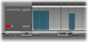
Chapter 14 Ultrabeat 376
•Create & Replace Many: Similar to Create & Replace Some, but a large number of new steps are
created, eectively lling the pattern.
For example, start with an empty sequence of 32 steps at 1/16 resolution. Using Create &
Replace Few creates 4 new steps; using Create & Replace Some creates 8 new steps; and using
Create & Replace Many creates 16 new steps.
Set step lengths and velocities
The Velocity/Gate row enables you to set the length (gate time) and velocity of the notes
entered in the Trigger row. Both parameters are displayed as a single graphical bar.
•The bar’s height represents note velocity.
•The bar’s width indicates the note length (gate time).
Change the length and velocity values for each step
Do either of the following:
mTo change the velocity, drag the blue bar vertically.
mTo change the note length (gate time), drag the blue bar horizontally.
The gate time is divided into four equal sections, making it easy to set rhythmically accurate
note lengths. For the one-shot envelope to react to gate time, it is necessary to either turn on
the Gate function in the sound itself (see Change Ultrabeat’s trigger mode on page 359) or use
envelopes in sustain mode (see Ultrabeat envelope parameters on page 368), in conjunction
with rhythmically useful (short) decay times.
Reset all velocity and gate values to default settings
mClick the Reset button at the left of the velocity/gate row.
The default velocity setting is 75 percent. The default gate value is all four sections active.
Use the Ultrabeat velocity/gate shortcut menu
mControl-click (or right-click) any step in the velocity/gate row to open a shortcut menu that has
the following commands:
•Alter Vel(ocities): Changes the velocity values of all steps by a random amount, while retaining
the selected beats (the Trigger row remains unchanged).
•Alter Gate (Time): Changes the note lengths of all steps by a random amount, while retaining
the selected beats (the Trigger row remains unchanged).
•Randomize Vel(ocities): Creates a new, random velocity value.
•Randomize Gate (Time): Creates a new, random gate value.

Chapter 14 Ultrabeat 377
Set Ultrabeat step sequencer accents
The Accent setting can be switched on or o individually for each drum sound. This enables you
to turn accents on for cymbals but turn accents o for the kick drum, for example.
Turn on accents and set the accent level
1 Click the blue LED to the right of the Accent slider to turn on the accent function.
2 Drag the Accent slider to globally set the volume of programmed accents.
Program an accent for a particular step
mClick the blue LED above the step (steps 1 and 3 in the gure).
The sound at this step position is accentuated (played louder).
Ultrabeat Step grid full view
Click the Full View button in the lower-right corner to see a large sequencer grid lled with
trigger buttons. The large grid simultaneously displays the 32 trigger buttons for all 25
drum sounds.
Full view provides an overview of the whole pattern, rather than a single drum sound sequence.
Because the trigger events for all sounds are shown, you can quickly identify accidental notes.
Full view also accelerates the pattern creation process.
The selected sound is highlighted with a gray box in the step sequencer area, making it easy
to set the velocity and gate time for each step or osets in Step mode (see Ultrabeat step
automation overview on page 378), within the context of all sequences/sounds in the pattern.
Both the grid and the Trigger and Gate/Length rows are displayed for the selected drum sound.
This makes it simple to create trigger events in the full view grid, then set accents in the Gate/
Length rows, for example.
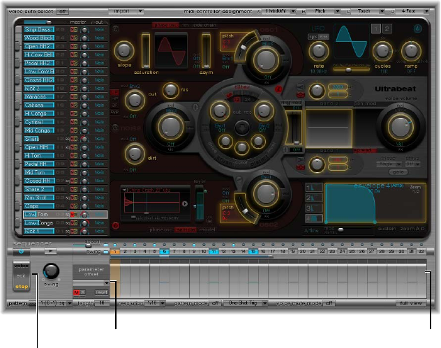
Chapter 14 Ultrabeat 378
Automate parameters in Ultrabeat’s step sequencer
Ultrabeat step automation overview
Click the Edit Mode switch to turn on Ultrabeat’s step automation feature. Step automation
enables you to program parameter changes on a per-step basis for each drum sound. Sound
parameters that can be automated include all functions in the Synthesizer section except:
•Menus (modulation routings and so on)
•Buttons (oscillator-type buttons, the buttons in the trigger/group section)
•Pan/Spread parameters
Edit Mode switch
Parameter offset row
Offset menu
When you turn on Step mode, Ultrabeat’s interface changes in the following ways:
•Yellow frames appear around all parameters that can be automated in the Synthesizer section.
Parameters that cannot be automated are still visible but are disabled.
•The velocity/gate row in the Step grid changes to show the (parameter) oset row.
Tip: When creating osets in step mode, you may want to make a change to the original drum
sound. Rather than switching back and forth between edit modes for this adjustment, you can
press Command-Option to temporarily ip Ultrabeat back into Voice mode.
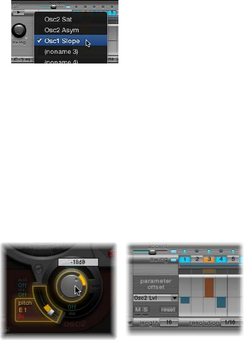
Chapter 14 Ultrabeat 379
Use Ultrabeat’s oset row
This row enables you to view and enter oset values on a per-step basis for all Synthesizer
section parameters that can be automated. Adjustments made in the oset row are relative to
the current parameter value. Values shown in the oset row will be either added to or subtracted
from the parameter value set in the Synthesizer section. In other words, parameter osets
increase or decrease, but do not specify, an absolute value for the parameter.
Parameter edits can be made in three ways:
•By editing oset values in the oset row.
•With the shortcut menu.
•By directly adjusting the controls in the Synthesizer section. All parameters that you automate
(create an oset for) are shown in the Parameter Oset pop-up menu.
Important: Moving a control element in the Synthesizer section will add the parameter to the
Parameter Oset pop-up menu, and will create an oset, so take care.
Create a parameter oset
1 Select the drum sound that you want to oset.
2 Click a position in the (parameter) oset row that corresponds to the step you want to edit.
3 Make the parameter change in the Synthesizer section. Your change will be recorded as an oset
value for this step.
4 Repeat step 3 for each parameter that you want to edit for this step.
A parameter oset that has been created for a given parameter on a given step is represented in
two ways.
•A yellow bar is drawn on the parameter that indicates the deviance (the oset) between the
original parameter value and the new parameter value.
•In the (parameter) oset row, the oset from the original parameter is represented as a bar
starting from the zero point (horizontal center line).
•Positive osets are shown as a bar above the center line.
•Negative osets are shown as a bar below the center line.

Chapter 14 Ultrabeat 380
Use the Ultrabeat parameter oset shortcut menu
mControl-click (or right-click) any step in the (parameter) oset row to open a shortcut menu, then
choose one of the following commands.
•Alter: Changes the (selected) parameter values, for all steps, by a random amount.
•Randomize: Creates a new, random value for the selected parameter.
Note: Consider saving your sequence/pattern before using either of the above commands.
•Delete: Deletes all steps for the currently selected parameter.
Mute, solo, and reset Ultrabeat parameter osets
mClick the M(ute), S(olo), and Reset buttons in the parameter oset row.
•M(ute): Mutes the osets of the selected parameter. This does not remove or reset
existing osets.
•S(olo): Enables you to hear the eect of your osets on the selected parameter only.
•Reset: All oset values for the selected parameter are set to zero (no oset). A second click on
the Reset button removes the parameter from the Parameter Oset menu.
Note: The Reset button at the left of the velocity/gate row changes to Delete when clicked
once. This Delete button mirrors the behavior of the Delete command: It deletes all steps for
the currently selected parameter.
Export Ultrabeat patterns as MIDI regions
Patterns programmed in Ultrabeat’s internal step sequencer can be exported as MIDI regions
into Logic Pro.
Export an Ultrabeat pattern into Logic Pro
1 Choose the pattern that you want to export from Ultrabeat’s Pattern pop-up menu.
2 Select the area to the left of the Pattern pop-up menu.
3 Drag the pattern to the target position on the respective Ultrabeat track.
A region is created containing all MIDI events, including Swing and Accent parameter settings.
Accents are interpreted as polyphonic pressure events. Step automation events, created in Step
mode, are also exported as part of the MIDI region.
Note: To avoid double-triggering while playing back the exported MIDI region, turn o
Ultrabeat’s step sequencer.

Chapter 14 Ultrabeat 381
MIDI control of Ultrabeat’s step sequencer
Pattern performance can be inuenced by incoming MIDI notes. This enables spontaneous
interaction with the step sequencer, making Ultrabeat an excellent live performance instrument.
The way Ultrabeat reacts to MIDI control is determined by the chosen pattern, playback, and
voice mute mode options.
Pattern Mode button Voice Mute Mode buttonPlayback Mode menu
MIDI control parameters
•Pattern Mode (On/O) button: Allows you to choose and start patterns with MIDI note
messages. The Transport button turns blue to indicate that Ultrabeat is ready to receive
incoming control commands.
MIDI notes C-1 to B0 switch between patterns: C-1 selects pattern 1, C#-1 selects pattern 2,
and so on up to pattern 24 (selected when MIDI note B0 is received).
•Playback Mode pop-up menu: Determines pattern playback behavior when an incoming MIDI
note is received. You can choose one of the following options:
•One-Shot Trig(ger): The reception of a MIDI note starts the pattern, which plays once through
its cycle, then stops. If the next note is received before the pattern has reached its nal
step, the new note stops playback of the rst pattern and the next pattern begins playing
immediately—this can be a dierent pattern or the same pattern, depending on the MIDI
note received. Note-o events are ignored.
•Sustain: The reception of a MIDI note starts the pattern and it continues playing in an innite
loop until the corresponding MIDI note is released (a note-o event is received).
•Toggle: The reception of a MIDI note starts the pattern and it continues playing in an innite
loop until the next note is received. If it is the same note, the pattern stops immediately. If it
is a dierent note, the sequencer immediately switches to the new pattern.
Toggle mode allows you to switch between patterns in the middle of a bar—the sequencer
stays in time and automatically jumps to the corresponding beat of the new pattern. This isn’t
the case in One-Shot Trig mode, which starts the new pattern from the beginning as soon as
you play a MIDI note.
•Toggle on Step 1: The behavior is the same as Toggle mode except that the pattern change or
stop occurs the next time beat 1 is reached—at the beginning of the next pattern cycle.
•Voice Mute Mode button: Playing MIDI note C1 and above mutes the corresponding sound in
the Ultrabeat mixer. A subsequent MIDI note of the same pitch unmutes it. This is ideal for
spontaneous rearranging of patterns and/or muting single elements of a pattern without
deleting them. This is especially useful in a live performance or remixing situation.
All the creative pattern switching options discussed in this section are achieved with MIDI note
messages and can be recorded, edited, arranged, and automated in Logic Pro.
Chapter 14 Ultrabeat 382
Ultrabeat tutorials
Ultrabeat sound programming overview
The Ultrabeat tutorials presented in these sections cover a number of specic sound creation
tips. These tutorials will help you explore the possibilities available to you in Ultrabeat.
You’ll discover that there is hardly a category of electronic drum sound that Ultrabeat can’t
create easily.
As you become familiar with drum sound programming, you may begin thinking in building
blocks, realizing that drum sounds usually consist of dierent components.
After you mentally—or physically—write down your list of components, try to emulate each
component that contributes to the sound’s character, making use of the dierent sound
generators available in Ultrabeat. Assigning dedicated amplitude envelopes to the dierent
components allows you to control their temporal behavior individually. For example, you can
emulate the body of a drum with oscillator 1 and the sound of the stick hitting the skin (or rst
transient) with the noise generator. Additional overtones and harmonics can be provided by
oscillator 2 or the ring modulator.
When you begin thinking that drum sounds consist of several building blocks or layers, the
design of the Volume controls in the individual sound generators might make more sense to
you—this is the place where the blocks are combined, balanced, and controlled.
Note: Choose the Tutorial Kit from Ultrabeat’s Settings > 03 Tutorial Settings folder. This kit
contains all drum sounds discussed in the tutorials. The Tutorial Kit also includes the Standard
Tut(orial) drum sound, which is a default set of neutral parameters that provide an excellent
starting point for many of the examples.
All Ultrabeat tutorial sections are listed below:
•Create Ultrabeat kick drums on page 383
•Create Ultrabeat snare drums on page 387
•Create Ultrabeat tonal percussion on page 392
•Create Ultrabeat hi-hats and cymbals on page 392
•Create metallic Ultrabeat sounds on page 393
•Tips for extreme Ultrabeat sounds on page 393
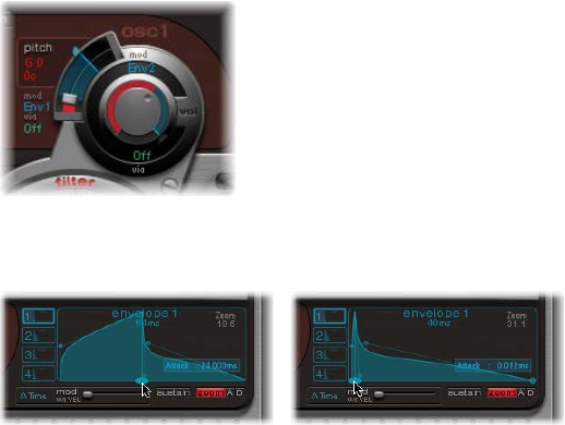
Chapter 14 Ultrabeat 383
Create Ultrabeat kick drums
Electronically produced kick drum sounds are based primarily on the sound of a deeply tuned
sine wave. Follow the tutorials sequentially to get the most from these examples.
Program a basic kick drum in Ultrabeat
1 Choose Settings > 03 Tutorial Settings > Tutorial Kit, and select Standard Tut from the
Assignment section.
Note that oscillator 1 is in Phase Oscillator mode.
2 Find a suitably tuned pitch in the lower octaves by soloing the bass drum along with other
important tonal elements of the song (a bass or pad sound, for example). Drag the Osc 1 Pitch
slider to adjust the pitch until appropriate.
3 Use Env 4 to shape the volume of the bass drum.
For slower beats you’ll want a longer decay phase, whereas at faster tempos you’ll choose a
shorter decay time. The attack time of Env 4 should be very short in any case (0, in most cases) or
the sound will lose its percussiveness and its ability to be clearly heard in the mix.
Give your drum more kick by controlling the pitch with an envelope
The kick drum still sounds very soft and is somewhat reminiscent of the famous TR-808 bass
drum. It’s still missing a clearly dened attack.
1 Make sure that Env 1 is chosen from the mod pop-up menu of oscillator 1’s Pitch parameter.
2 Set the degree of modulation by dragging the blue Mod slider approximately 3 to 4 octaves
above the original pitch.
3 Set the attack time in Env 1 to 0 by dragging the leftmost of the two junction points on the
x-axis all the way to the left.
4 Experiment with the decay time by dragging the rightmost of the two junction points on the
x-axis. You’ll discover that higher decay values (shifting the Bezier handle to the right) result
in sounds similar to synth toms, whereas shorter decay values (shifting to the left) provide the
kick character.
5 Change the Mod amount (the blue slider) of Osc 1 Pitch again (see step 2).
The interaction of this parameter with the envelope’s decay time provides numerous possibilities
for shaping the kick or punch of the bass drum sound.
Note: This simple bass drum sound is listed as Kick 1 in the Tutorial Kit, at a pitch of C1.

Chapter 14 Ultrabeat 384
Reduce kick drum tonality using the 2 Band EQ
One advantage of bass drums based on sine waves is that their sound can be precisely tuned to
match the song. The disadvantage is that a recognizable pitch is not always desirable. Ultrabeat
oers several methods to reduce the tonality of the sound. A very eective tool is the 2 Band EQ.
1 For band 1, select the Shelving mode at a frequency of about 80 Hz, a high Q value, and a
negative Gain value.
2 For band 2, select the Peak mode at a frequency of around 180 Hz, a medium Q value, and also a
negative Gain value.
On the EQ graph, notice how the frequencies around 80 Hz are boosted, while the surrounding
frequencies are reduced.
3 Vary the frequency of band 2 (easily recognizable in the blue part of the EQ graph) to inuence
the extent of bass drum tonality.
Reduce kick drum tonality with a lowpass lter
A further method for reducing the tonality of a drum sound that is rich with overtones is to use a
lowpass lter. In this example you will control the cuto frequency of the lter with an envelope.
1 Reload the Standard Tutorial sound, choose A#0 as the basic pitch in oscillator 1, and modulate it
with Env 1.
2 Increase the Saturation parameter value to enhance the overtones of the drum sound.
Note that the output of Osc 1 is directed to the lter, because the lter bypass button (the arrow
between Osc 1 and the lter) is activated.
3 Set Filter type to LP 24.
4 Set Cuto value to 0.10.
5 Set Mod Source for Cut to Env 3.
6 Set Mod Amount for Cut to 0.60.
7 Set Resonance to 0.30.
8 Set the attack time of Env 3 to 0. Use the Decay time of Env 3 to shape the sound of the ltered
bass drum.
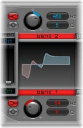
Chapter 14 Ultrabeat 385
9 You may also choose to control the lter resonance with an envelope. Make sure you dedicate
a single envelope to this function (in this case, use Env 2 as a Mod source for Res). Choose a
Mod amount for Res of about 0.80. Select a longer decay time in Env 2 than in Env 3 and listen
carefully to the fatter and more atonal bass drum sound achieved through this Res modulation
(due to the higher lter resonance).
Note: The bass drum described in the above example is listed as Kick 2 in the Tutorial Kit, at a
pitch of C#1. It also features an interesting EQ setting, as described in “Add body and bite to your
kick drum”.
Add body and bite to your kick drum
Do any of the following:
mAdd some bass to your sound:
Use the Kick 2 ltered bass drum sound as a starting point, and try out the remaining parameters
in the phase oscillator. You will discover that high saturation values make the sound rounder and
add more bass, for example. The character of the example is beginning to head in the direction
of a TR-909.
mEnhance the attack transients of your sound:
To get even closer to the TR-909, use an EQ setting as shown in the following gure. Note that
the low frequency pressure point around 60 Hz (in the red area on the EQ graph) as well as
the assertive punch or kick (the blue area starting at 460 Hz and up) of a 909 bass drum are
strengthened. (This EQ setting is already part of the Kick 2 setting.)
mUse envelopes to change the color of your sound:
In the example, all four envelopes are being used. Take some time to play with the shapes of
the envelopes, while maintaining the attack and decay settings. Experiment with the junction
points of the decay phase in the dierent envelopes to familiarize yourself with the sound-
shaping options available. Start with the decay phase of Env 4, which controls both the volume
of oscillator 1 and lter resonance, and observe how reshaping the belly of the envelope can
change the character of the sound from crisp and short to round and full.
Chapter 14 Ultrabeat 386
Create an LFO-modulated “Ultrabeat” kick drum
You can create bass drum sounds that are uniquely “Ultrabeat.” Try modulating pitch with an LFO
instead of an envelope, for example.
1 Start with the Standard Tutorial sound at a pitch of A#0 (Osc 1 Pitch), and choose LFO 1 as the
Mod source in the Osc 1 Pitch section.
2 Set the degree of modulation by dragging the blue Mod slider to a value of A3.
3 Set LFO 1 to a low number of Cycles (25 to 35), a high Rate (starting with 70 Hz and higher) and a
medium value for Decay (set the Ramp knob to about −190).
4 Experiment with the LFO waveform and you’ll discover that you can attain dierent nuances in
the character of the bass drum attack.
5 Modulate the Asym(metry) parameter with the same LFO, and also vary the Slope and
Saturation values.
This method enables you to create very dierent bass drum sounds with a single oscillator, one
LFO, and one envelope (for volume). The character of the sounds can range from soft to punchy,
and the degree of tonality in the sound can be adjusted to taste.
Note: The bass drum sound described is listed as Kick 3 in the Tutorial Kit, at a pitch of D1.
Use the second oscillator (with similar settings or with a sample), or use the lter and the ring
modulator—the sky’s the limit as far as your imagination is concerned, so go ahead and create
that next “gotta have it” drum sound.
Note: You can nd an “emulation” of the legendary 808 bass drum in Kick 4 in the Tutorial Kit, at
a pitch of D#1.
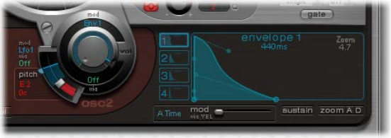
Chapter 14 Ultrabeat 387
Create Ultrabeat snare drums
The sound of an acoustic snare drum consists primarily of two sound components: the sound
of the drum itself and the buzzing of the snare springs. Try to approximate this combination in
Ultrabeat with a single oscillator and the noise generator. Follow the tutorials sequentially to get
the most from these examples.
Create a basic snare drum
1 Load the Standard Tutorial setting.Turn o oscillator 1, and turn on oscillator 2 (in phase oscillator
mode).
2 Choose LFO 1 from the mod pop-up menu of Osc 2 Pitch.
3 Set the pitch value for Osc 2 to around G#2 and set the Mod amount (the blue Mod control) to
about 3 to 4 octaves higher.
You have modulated Osc 2 Pitch with a rapidly vibrating LFO with a medium Ramp Decay value.
This eliminates the sine wave—which is not especially desirable for a snare sound, in contrast to
the bass drum.
4 Set LFO 1 to a high Rate. Choose a value of 20 for Cycles and −20 for Ramp. Set the LFO
Waveform parameter to a value of about 0.58, which is a square wave.
5 Use Env 1 to control the volume of oscillator 2 by setting Vol to the lowest possible value
(−60 dB), choosing Env 1 from the mod pop-up menu, and adjusting the modulation intensity to
a point just below its maximum value.
The gure shows the settings of oscillator 2 and Env 1.
6 Experiment with dierent Slope and Asym values to impart a more or less electronic character to
the sound.
7 Turn on the noise generator and control its volume with the same quick envelope used in
Osc 2 Volume.
8 Use the lter parameters of the noise generator to roughen up, rene, or add bright frequencies
to the noise component of the snare drum sound. Select an LP lter type, and try a lter
frequency between 0.60 and 0.90. Modulate it with LFO 1, which you’re already using to control
the pitch of oscillator 2.
Note: The snare drum sound is listed as “snare 1” in the Tutorial Kit, at a pitch of E1.
Chapter 14 Ultrabeat 388
Rene the snare drum sound using FM synthesis
1 Turn on oscillator 1 in FM mode. Use Env 1 to control the volume of Osc 1 as well.
2 Choose a pitch for oscillator 1 that’s about an octave lower than oscillator 2. Consciously avoid
even intervals between the oscillators and detune them slightly from each other. For example,
try a pitch setting of F#2 in Osc 2 and E1 in Osc 1, then ne-tune Osc 1 a few cents higher by
holding down Shift while adjusting the Osc 1 Pitch slider.
3 Experiment with FM Amount, and add more tone (low FM Amount) or noise (more FM Amount)
as desired. Also try modulating the FM Amount with a fast LFO.
Higher FM Amount values lead to considerably more overtones and a very electronic sound
character. If you want to make the sound more acoustic, feed oscillator 1 (and possibly
oscillator 2 as well) into the main lter. Use these settings to start: LP 24 mode and a Cuto value
of about 0.60.
Note: An exemplary snare drum sound that uses FM can be found in the Tutorial Kit at a pitch of
F1. It is listed as “snare 2.”
Recreate the 808 snare sound
The famous 808 snare is based on two resonating lters and a noise generator, fed through a
highpass lter. The mix ratio of the two lters and the volume of the noise generator can be
adjusted. This structure cannot be 100% replicated in Ultrabeat.
1 Load the Standard Tutorial setting.
You are now ready to replicate the resonating lters of the 808 snare using two cleverly
programmed phase oscillators.
2 Assign slightly dierent Slope values to two phase oscillators, and detune them by almost
an octave.
3 Adjust the tonal relationship between the oscillators so that it is uneven—from E3 to F2,
for example.
4 Control the volume of each oscillator with a dierent envelope. Adjust the decay times so
that the envelope for the lower-tuned oscillator has a longer decay time than the very snappy
envelope setting for the higher oscillator.
5 Feed the output of both oscillators into Ultrabeat’s main lter, and hollow out the sound with a
highpass lter. Activate the lter bypass button in both oscillators. Choose the HP 12 setting in
the lter, a Cuto value around 0.40, and a Resonance value of about 0.70.
You have just cleverly emulated both of the 808’s resonating lters. Shifting the pitch of both
oscillators simulates the behavior of the 808’s Tone control.
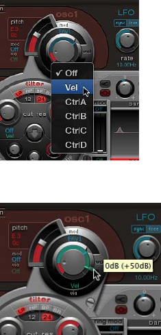
Chapter 14 Ultrabeat 389
Complete the 808 emulation by adding some noise
1 Switch the noise generator on, and activate the highpass mode in its lter (HP).
2 Set the Cuto value to about 0.65, Resonance to 0.35, and add a little Dirt (around 0.06).
The noise generator provides the sustained snare sound. It should be shaped by its own
envelope—independent of the decay phases of both oscillators—to get 808-like results.
Changing the volume of the noise generator simulates the snap parameter of the 808.
Note: The 808 snare drum described is listed as “snare 3-808” in the Tutorial Kit, at a pitch of F#1.
It also features an interesting EQ setting.
Use velocity modulation on your 808 snare
Use the 808 snare drum sounds in the Tutorial Kit to explore the possibilities Ultrabeat oers for
implementing velocity.
1 Select the “snare 3-808” sound.
2 Chose Vel from the via pop-up menu below the oscillator 1 Volume knob.
A slider appears on the ring around the knob.
3 Drag the slider clockwise. When you drag the slider, a help tag displays the value. Set it to 0 dB.
4 Repeat steps 2 and 3 in both oscillator 2 and the noise generator.
You can now dynamically play the sound using velocity.

Chapter 14 Ultrabeat 390
Increase the performance dynamics of your 808 snare
1 Reduce the values of the individual volumes by turning down the Volume knobs in both
oscillators and the noise generator. Note how the mod ring and its via sliders also move back.
Change the via slider positions until all three Volume knobs look like this:
If you use diering intensities for each Volume knob when completing this step, you’ll have the
potential of individual velocity reactions for each sound component.
2 Increase the dynamics of the sound as a whole by assigning the following setting to the Voice
Volume knob:
You now have an 808 snare that is exceptionally responsive to velocity. As you may know, this
wasn’t possible with the original—not even an 808 sample could oer the dynamic volume
control of individual sound components that’s demonstrated here. A sample oers you only the
whole sound, not its constituent parts.
In the next step, you use velocity to control the character of the sound—individually for each
component—plus volume, of course.
3 Choose Max from the saturation mod pop-up menu of oscillator 2, and then choose Vel(ocity)
from the corresponding via pop-up menu.
4 Set the additional control that appears as shown in the gure below, to control the character of
the sound with velocity:
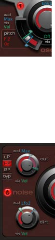
Chapter 14 Ultrabeat 391
5 Repeat this with the other parameters of oscillator 2, as well as pitch:
6 Modulate the noise generator as follows:
•Cut parameter: Choose Max as modulation source, then set the modulation control as
shown below.
•Dirt parameter: Choose LFO 2 as modulation source, then set the modulation control as
shown below.
The sound is now nothing like an 808 snare, which was your goal. Keep experimenting with
velocity and gure out when it makes sense to use it as a direct or indirect modulation source, in
either its positive or negative form.
Recreate the Kraftwerk snare sound
Another classic electronic snare drum sound is the highly resonant lowpass lter of an analog
synthesizer that quickly closes with a snap. This sound was used extensively by Kraftwerk.
1 Select the Snare 1 sound.
2 Direct the signals of both oscillators and the noise generator to the main lter.
3 Modulate Cuto with Env 1 (which is already modulating the volume of the noise generator).
4 Modulate the lter resonance with Env 2.
5 Experiment with the parameters mentioned in steps 2 to 4 (especially the envelopes), introduce
EQ into the sound, and discover how much “playing room” these basic settings allow you.
Note: An exemplary sound is listed as “snare 5-KW” in the Tutorial Kit, at a pitch of G#1. Analyze
this sound, and compare it to your own creation.
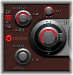
Chapter 14 Ultrabeat 392
Create Ultrabeat tonal percussion
Tonal percussion sounds such as toms or congas are relatively easy to emulate electronically with
sine or triangular wave oscillators. Ultrabeat’s phase oscillator oers you a broad spectrum of
suitable basic sounds with which to start. Control the pitch of the oscillators with envelopes, and
use the programming techniques discussed in the kick and snare drum sections to alter tonality.
You should nd it easy to create a broad range of toms and similar sounds. See Create Ultrabeat
kick drums and Create Ultrabeat snare drums.
Use oscillator 2 model mode to create tonal percussion sounds
mTurn on oscillator 2 Model mode, then familiarize yourself with the eect of each parameter. You
should nd it is quite easy to create your own tonal percussion sounds, ranging from toms, to
small tabla drums, to glass bowls.
•Note pitches A1 to B0 in the Tutorial Kit contain typical 808 toms. Analyze these sounds and
modify them as you see t.
•Note pitches C2 and C#2 in the Tutorial Kit contain tabla and glass sounds that combine
both Osc 2 Model and FM. They are also good examples of the complex use of velocity as a
modulation source.
Create Ultrabeat hi-hats and cymbals
Electronic hi-hat sounds are easy to create in Ultrabeat.
Create a hi-hat in Ultrabeat
1 Load the Standard Tutorial sound.
2 Turn o oscillator 1 and turn on the noise generator.
3 In the noise generator, make sure the Cuto parameter is modulated by Env 1, the modulation is
negative, and the position of the Mod slider is below that of the base parameter value.
4 Use rather short decay values for Env 1 and Env 4.
5 Set the attack time of Env 4 to a value of 0. The attack time of Env 1 should also be rather short,
but not equal to 0.
Note: You’ll nd a similarly constructed sound listed as “hihat 1” at a pitch of F2 in the Tutorial Kit.
Also analyze the hi-hat sound “hihat 2” at pitch F#2.
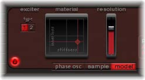
Chapter 14 Ultrabeat 393
Create cymbals in Ultrabeat
It’s not far from the hi-hat to the crash cymbal. The main dierence between a hi-hat and crash
cymbal sound is the length of the decay time. Correct assignment of the envelopes is the key to
producing dierent cymbal sounds.
mSelect the Cym 1 and Cym 2 sounds in the Tutorial Kit and try dierent envelope assignments
and settings for Cuto and Volume in the noise generator, Cuto and Volume in the main lter,
and so on.
Create metallic Ultrabeat sounds
If you want to create metallic sounds with Ultrabeat, the ring modulator and the Model oscillator
are the ideal tools.
Use the ring modulator to create metallic sounds
1 Load the Standard Tutorial sound.
2 Activate a phase oscillator and the Model oscillator. Choose a pitch for each oscillator above C3
so that a slightly detuned interval is created.
3 In the Material Pad of the Model oscillator, choose a setting with plenty of overtones, as in the
gure below.
4 Set the volume of each oscillator to a value of −60 dB, and click “ring mod” to turn on the
ring modulator.
You’ve just created a bell-like sound that you can lter with a high resonance value if required.
Note: You can nd a similar sound listed as Ring Bell at a pitch of A2 in the Tutorial Kit.
Tips for extreme Ultrabeat sounds
Ultrabeat features extremely fast envelopes and uncommonly powerful LFOs. Use these
modulation sources to perform extreme modulations of the oscillator and lter parameters.
Do any of the following:
•Try modulating as many targets as possible.
•Use a quick envelope to drive the lter to self oscillation for a fraction of a second.
•Use a few LFO cycles at a much higher rate than other cycles.
•Experiment with the Dirt parameter or the bit crusher.

394
Vintage B3 overview
Vintage B3 emulates the sound and features of the Hammond B3 organ with two manuals
(keyboards) and a pedalboard, each of which can have its own registration (sound setting). You
can play all registers with a single-manual master keyboard, or you can use two manuals and a
MIDI pedalboard. Vintage B3’s Component modeling synthesis engine faithfully replicates the
tonewheel generators of an electromechanical Hammond organ, down to the smallest detail.
This includes charming aws, such as the Hammond’s enormous level of crosstalk and the
scratchiness of the key contacts. You can adjust the intensity of these characteristics, enabling
tones that range from awlessly clean through to dirty and raucous—or anything in between.
Vintage B3 also simulates various types of Leslie sound cabinets—with rotating speakers, with
and without deectors. A exible integrated eects section provides tube overdrive, an equalizer,
a wah wah, and a reverberation eect.
The interface is divided into two main areas with a third area visible in some windows. The
control bar at the top lets you access dierent controls in windows shown in the central display
section. The lower edge gives you direct access to Leslie speed controls when the Main or Rotor
Cabinet window is shown.
Click the control bar buttons to update the central display.
•Main button: Shows the draw bars, which are used to make changes to the basic organ sound
in real time. Additional performance and setup controls can be accessed with the Control,
Preset, and Split buttons in the lower-right corner. See Vintage B3 Main window overview.
•Rotor Cabinet button: Shows the Leslie speaker cabinet model and control parameters. See
Vintage B3 Rotor Cabinet window overview.
•Options button: Shows several tone controls that provide quick access to various aspects of
your sound. Advanced controls for Percussion, Scanner Vibrato, and Morph are also found in
the Options window. See Vintage B3 Options window overview.
•Eects button: Shows controls for the built-in EQ, Wah, Distortion, Chorus, and Reverb eects.
See Use Vintage B3 eects.
•Expert button: Shows Organ, Pitch, Condition, Sustain, and Miscellaneous controls. These
provide precise control over the tone of the organ and over other aspects, such as tuning,
draw bar leakage, key click characteristics, and crosstalk levels. You generally access
these parameters only when editing or creating an organ sound. See Vintage B3 Expert
window overview.
Vintage B3 15
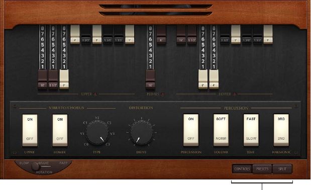
Chapter 15 Vintage B3 395
Vintage B3 Main window
Vintage B3 Main window overview
The Vintage B3 Main window is divided into three areas. The draw bars change the basic organ
sound in real time. See Vintage B3 draw bar controls. Click the Control, Preset, and Split buttons
at the lower right to show dierent parameters below the draw bars. The lower edge gives you
direct access to Leslie speed controls.
Click to show different
parameters below the
draw bars.
•The Scanner Vibrato, Distortion Drive, and Percussion controls are shown below the draw
bars when the Control button at the lower right is turned on. These add a vibrato or chorus-
like eect, an overdrive, or percussive element to your organ sound. See Vintage B3 Scanner
Vibrato and Chorus, Vintage B3 Distortion eect, and Vintage B3 Percussion eect.
•The Preset (registration) and Morph controls are shown below the draw bars when the Preset
button at the lower right is turned on. See Use Vintage B3 preset keys and Vintage B3 Morph
parameters.
•MIDI keyboard controls are shown below the draw bars when the Split button at the lower
right is turned on. See Vintage B3 MIDI setup overview.
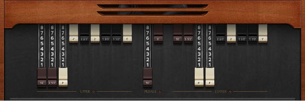
Chapter 15 Vintage B3 396
Vintage B3 draw bar controls
Vintage B3 provides 20 draw bars, nine each for the upper and lower manuals, and two for the
pedalboard. The upper manual draw bars are on the left, the pedal draw bars are in the center,
and the lower manual draw bars are to the right.
The draw bars behave like reversed mixer faders—the farther down you drag the draw bars, the
louder the selected sine choirs will be. MIDI control of the draw bars is also reversed when using
a standard MIDI fader unit.
Each sine choir is a sine wave that is mixed in at a particular level, determined by the draw
bar position. You add sine choirs in this way to build up the overall organ sound for the upper
or lower manual. This is a basic form of additive synthesis; for more information, see Additive
synthesis with draw bars on page 428. You can intuitively pick up the fundamental principles of
additive synthesis by playing a little with the draw bars.
Two draw bars are available for the bass pedals. The waveform used for the bass pedal sound is
not a pure sine wave, like the waveforms used for the upper and lower manuals. The pedalboard
sound uses a mixed waveform, which accurately emulates the B3’s bass tones. The two registers
dier in pitch, with the left, 16-foot register containing more octave harmonics. The right, 8-foot
register has a more prominent fth portion (fth harmonics are enhanced). The term foot is
derived from pipe organ lengths.
You can simulate the behavior of the Model A, the rst Hammond organ ever made. This model
had no foldback for the 16' draw bar in the lowest octave, with the bottom 12 tone generator
outputs available on the rst draw bar of the manuals’ bottom octave. Without foldback, the
sound is more strident and similar to the pedal sound. Click the disclosure triangle at the lower
left, then choose “all the way down” from the Bass pop-up menu to simulate the Model A.
Chapter 15 Vintage B3 397
Vintage B3 Scanner Vibrato and Chorus
Vintage B3 emulates the Scanner Vibrato of the original B3. Few organ players use the Scanner
Vibrato, preferring to work with a Leslie in isolation. Others, like B3 virtuoso Brian Auger, prefer
the integrated organ vibrato over the Leslie. Compare the chorus and vibrato eects with the
sound of the rotor cabinet simulation to see which you prefer.
The Scanner Vibrato is based on an analog delay line, consisting of several lowpass lters. The
delay line is scanned by a multipole capacitor that has a rotating pickup. It is a unique eect that
cannot be simulated with low frequency oscillators (LFOs). The vibrato of the organ itself should
not be confused with the Leslie eect, which is based on rotating speaker horns. Vintage B3
simulates both.
The (Scanner Vibrato) Chorus eect is derived from mixing the vibrato signal with the original,
statically pitched signal. The organ’s chorus sounds dierent from modern chorus eects.
Important: Scanner Vibrato and Chorus controls are spread across two windows. Click Main in
the control bar, then click the Control button at the lower right to view the On and O switches
and to choose the vibrato or chorus type. Click the Options button in the control bar to use the
Rate and Depth controls in the Options window.
Scanner Vibrato and Chorus parameters
•Upper and Lower switches (Main window): Switch the scanner vibrato on or o, independently,
for the upper and lower manuals. The treble portion of the organ is boosted slightly when
any vibrato setting is used. Because the B3 mixes the bass register (pedal) signal with the
lower manual signal, the pedal register is also aected by the lower manual’s scanner vibrato
settings.
•Type knob (Main window): Choose from three Vibrato positions (V1, V2, and V3) or three Chorus
positions (C1, C2, and C3). In the Vibrato positions, only the delay line signal is heard, and
like the Hammond B3, Vintage B3 vibrato types have dierent intensities. The three Chorus
positions (C1, C2, and C3) mix the signal of the delay line with the original signal.
•Rate knob (Options window): Rotate to set the vibrato or chorus speed.
•Depth knob (Options window): Rotate to mix the dry signal with the vibrato signal. This
parameter is active only when one of the chorus settings is engaged (C1, C2, or C3).
Chapter 15 Vintage B3 398
Vintage B3 Percussion eect
Vintage B3 emulates the (Key) Percussion features of the original B3. The Percussion function is
available only for the upper manual. The eect adds the second or third harmonics to the attack
envelope of a note. These harmonics quickly fade out, leaving the chosen draw bar tones.
The Percussion eect is polyphonic, but is only (re)triggered after all keys have been released.
If you release all keys, new notes or chords sound with percussion. If you play legato, or sustain
other notes on the upper manual, no percussion is heard.
Important: Percussion controls are spread across two windows. Click Main in the control bar,
then click the Control button at the lower right to view the Percussion, Harmonic, Time, and
Volume switches in the Main window. Click the Options button in the control bar to use the
advanced percussion controls in the Options window.
Percussion eect parameters
•Percussion switch (Main window): Turn on to activate percussion for the upper manual.
•Harmonic switch (Main window): Determines which harmonic is heard (the button toggles
between the 2nd and 3rd harmonic).
•Time switch (Main window): Switch between a slow or fast decay. The time is set with the Time
knobs in the Options window.
•Volume switch (Main window): Switch between a low or high decay level. The level is set with
the Volume knobs in the Options window.
•Mode switch (Options window): Choose Mono to trigger the percussion eect with each key
press. Choose Poly for a polyphonic percussion eect which is only (re)triggered after all keys
have been released. If you release all keys, new notes or chords will sound with percussion. If
you play legato, or sustain other notes on the upper manual, no percussion is heard.
•Perc on Preset switch (Options window): Set to B0 to simulate the B preset key restriction.
Choose All if you want percussion to always be available.
•Time knobs (Options window): Rotate to set an independent percussion decay time for the slow
and fast Time switch settings. When the Slow knob is set to maximum, the percussion doesn’t
decay at all.
•Volume knobs (Options window): Rotate to set an independent low and high decay level for the
low and high Volume switch settings. This is an improvement from the B3, where Time and Vol
could only be turned on or o.
•Upper Level knob (Options window): Rotate to set the balance between the upper (percussive)
manual and the lower manual/pedals. On the B3, percussion is available only if the B preset
key is selected (see Use Vintage B3 preset keys).
•Velocity knob (Options window): Rotate to set the percussion velocity sensitivity (unlike the
original B3, which is not velocity sensitive). Engaging percussion on a B3 slightly reduces the
volume of the normal, nonpercussive registers.
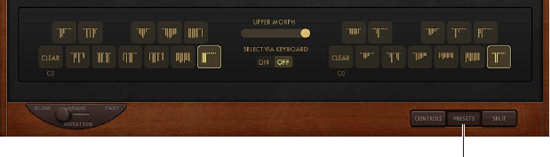
Chapter 15 Vintage B3 399
Use Vintage B3 preset keys
The Hammond B3 is equipped with 12 buttons, located below the draw bars. These preset keys
are laid out like a keyboard octave, but with black keys and white sharps. They are used to recall
draw bar registrations (draw bar positions).
Click to view preset keys.
Upper manual preset keys are to the left of the Upper Morph slider, and lower manual preset
keys are to the right. Draw bar positions are indicated by small vertical lines on each key. These
miniature draw bar representations update in real time. You can edit the draw bars of recalled
presets immediately, with changes to draw bar positions being automatically memorized as you
make them. You can, however, use the Save To function to save a registration to a specic preset
key (see Save a registration while morphing).
Important: The presets relate only to the registration (draw bar) settings of a single manual.
They do not store vibrato or other parameter settings. If you want to save and recall the
overall instrument settings (including eects), use the Settings pop-up menu in the plug-in
window header.
On keys C# to A#, the percussion works only if the Perc parameter is set to Always (see Vintage
B3 Percussion eect).
Vintage B3’s default range for preset (registration) keys spans MIDI note numbers 24 to 35 (C0
to B0). This means that the lowest playable MIDI note number is 36 (C1). You can transpose the
keyboard range in your host application or Vintage B3 itself. A 61-note keyboard—which spans
notes C to C—can be played across the entire range when the Transpose values of your host
application are set to 0. The preset (registration) keys are positioned one octave below this
transposed or non-transposed range. See Transpose keyboard zones by octaves on page 403.
Choose a registration
1 Click Main in the control bar, then click the Preset button at the lower right.
2 Click a preset key shown to the left (upper manual) or right (lower manual) of the Upper
Morph slider.
3 Play one of the preset key MIDI notes (MIDI note numbers 24 to 35).
Initialize a registration
1 Click Main in the control bar, then click the Preset button at the lower right.
2 Click the C key for the upper or lower manual. The lowest preset key (shown as “C”) is the Clear
key. The other 11 keys, from C# to B, recall registrations.
3 Play MIDI note number 24.
Chapter 15 Vintage B3 400
Switch Vintage B3 registrations while playing (organ gate eect)
1 Click Main in the control bar, then click the Preset button at the lower right.
2 Hold the Clear key (C) on your master keyboard with the small nger of your left hand, while
sustaining a chord with your right hand.
3 Press the preset keys with the other ngers of your left hand.
The chord being played with your right hand is retriggered (with the new registration) each time
you play one of the preset keys. This two-handed technique results in an organ-specic gate-
type eect. Each time you switch to a new registration, the chord is retriggered.
Disable MIDI preset key switching
Disabling the switching of presets with MIDI notes 24 to 35 eliminates problems that may arise
from transpositions.
1 Click Main in the control bar, then click the Preset button at the lower right.
2 Turn o Select via Keyboard.
Switch Vintage B3 registrations with a two-draw bar controller
When you use a two-draw bar hardware controller, there is an additional mode that allows
Hammond-like switching between two registrations. By default, moving draw bars always
changes the registration of the currently active preset registration key. This works dierently in
a real Hammond organ, where the draw bars aect only the A# (upper manual) and B (lower
manual) preset registrations. This feature allows you to prepare a new registration with the draw
bars while playing, then switch to the new registration when needed.
1 Open the Options window, then choose the (Edit/Preset Key) A# and B only switch position.
The upper manual draw bars can now change the registration of the A# preset key, and the draw
bars of the lower manual aect the B preset key.
2 Change the draw bars of the A# preset key. You can play the keyboard while doing so, without
changing the currently chosen registration.
3 Switch to the prepared registration with the A# preset key.
Chapter 15 Vintage B3 401
Set up Vintage B3 for your MIDI equipment
Vintage B3 MIDI setup overview
Vintage B3 is unique among the instruments in that it can be played with three simultaneous
controllers—namely, a MIDI bass pedal unit and two 73-key MIDI keyboards. This mirrors the two
73-key manuals (organ terminology for keyboards) and the 2-octave pedalboard conguration of
the original B3. See Use multiple or multichannel controllers for more information.
Vintage B3 can also be played with a standard 61-key (5 octaves C to C) MIDI keyboard. See Use a
single-channel controller for more information.
Vintage B3 also emulates the B3’s preset keys—the lowest octave of attached MIDI keyboards
can switch between Vintage B3 registrations. This matches the behavior of the original B3, which
features a number of inverted (black) keys in the lowest octave of each manual. These inverted
keys are used as buttons that recall preset registrations (a preset of your draw bar settings). See
Use Vintage B3 preset keys.
For information about setup and use of dedicated MIDI draw bar controllers, see Choose a
Vintage B3 MIDI control mode.
Use multiple or multichannel controllers
By default, Vintage B3 receives the notes for the upper and lower manuals, and for the
pedalboard, on three consecutive MIDI channels, mapped as follows:
• MIDI channel 1: You play the upper manual sound.
• MIDI channel 2: You play the lower manual sound.
• MIDI channel 3: You play the pedalboard sound.
This allows you to simultaneously play Vintage B3 with up to three MIDI controllers. You can
also use a single-manual master keyboard—with dierent keyboard zones, or a keyboard split
feature—that sends data on dierent MIDI channels to address all three Vintage B3 sounds
simultaneously. Each keyboard zone can be transposed independently. See also Choose a
Vintage B3 MIDI control mode. You can use any of your MIDI interface inputs for your master
keyboard or pedalboard. Regardless of the input devices used, the only relevant factor is the MIDI
send channel.
Note: See the user manual for your master keyboard to learn how to set up splits and zones or
how to set its MIDI transmission channel (often called TX Channel).
Set the keyboard mode
There are three keyboard modes: single, split, and multi.
1 Click Main in the control bar, then click the Split button at the lower right.
2 Set the switch to the left of the keyboard in the central display to Single, Split, or Multi.
•Single: Uses the entire keyboard. You can only play the upper sound.
•Split: Divides the keyboard into two. You can play the upper and lower sounds in dierent
keyboard zones.
•Multi: Divides the keyboard into three. You can play the upper, lower, and pedalboard sounds
in dierent keyboard zones.
Chapter 15 Vintage B3 402
Change the default MIDI channels
Changing MIDI channels can be useful when you perform live and require quick access to
another sound module.
1 Click Main in the control bar, then click the Split button at the lower right.
2 Set the switch to the left of the keyboard in the central display to Multi.
3 Change the channel numbers for the upper, lower, and pedal manuals.
Set keyboard zones
1 Click Main in the control bar, then click the Split button at the lower right.
2 Set the switch to the left of the keyboard in the central display to Split.
3 Horizontally drag the split icons to create the pedal/lower zone and the lower/upper zone.
If you select the same value for both split points, the lower manual is turned o. If the lower/
pedal split is moved above the upper/lower split, the other split point is moved (and vice versa).
Transpose keyboard zones by octaves
You can make transpositions that are independent of the global Tune parameter or transposition
features of the host application. These have no impact on the preset keys which is particularly
important when you want to use preset switching (see Use Vintage B3 preset keys) when split
keyboard mode is active.
1 Click Main in the control bar, then click the Split button at the lower right.
2 Set the switch to the left of the keyboard in the central display to Split.
3 Choose an octave value (+/– 2 octaves) from the Pedal Transpose, Lower Transpose, or Upper
Transpose pop-up menu.
Use a single-channel controller
If you don’t have a master keyboard that allows multichannel transmission, you can use a MIDI
keyboard that is capable of transmitting on only one MIDI channel. You can use Vintage B3 Split
parameters to split the keyboard in order to play upper, lower, and pedal sounds in dierent
keyboard zones. Each keyboard zone can be transposed independently.
There are three keyboard modes: single, split, and multi.
•Single: Uses the entire keyboard. You can only play the upper sound.
•Split: Divides the keyboard into two. You can play the upper and lower sounds in dierent
keyboard zones.
•Multi: Divides the keyboard into three. You can play the upper, lower, and pedalboard sounds
in dierent keyboard zones.
Technically, Vintage B3 remaps the incoming single-channel MIDI data into two or three MIDI
channels when either split or multi keyboard mode is active.
Set the keyboard mode
1 Click Main in the control bar, then click the Split button at the lower right.
2 Set the switch to the left of the keyboard in the central display to Single, Split, or Multi.
Chapter 15 Vintage B3 403
Change the default MIDI channels
Changing MIDI channels can be useful when you perform live and require quick access to
another sound module.
1 Click Main in the control bar, then click the Split button at the lower right.
2 Set the switch to the left of the keyboard in the central display to Multi.
3 Change the channel numbers for the upper, lower, and pedal manuals.
Set keyboard zones
1 Click Main in the control bar, then click the Split button at the lower right.
2 Set the switch to the left of the keyboard in the central display to Split.
3 Horizontally drag the split icons to create the pedal/lower zone and the lower/upper zone.
If you select the same value for both split points, the lower manual is turned o. If the lower/
pedal split is moved above the upper/lower split, the other split point is moved (and vice versa).
Transpose keyboard zones by octaves
1 Click Main in the control bar, then click the Split button at the lower right.
2 Set the switch to the left of the keyboard in the central display to Split.
3 Choose an octave value (+/– 2 octaves) from the Pedals Transpose, Lower Transpose, or Upper
Transpose pop-up menu.
These transpositions are independent of the global Tune parameter or transposition features of
the host application. They also have no impact on the preset keys which is particularly important
when you want to use preset switching (see Use Vintage B3 preset keys) when split keyboard
mode is active.
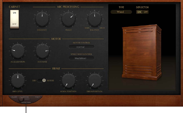
Chapter 15 Vintage B3 404
Vintage B3 Rotor Cabinet window
Vintage B3 Rotor Cabinet window overview
The Hammond story can’t be fully told without discussing the rotor cabinets manufactured by
Leslie. In fact, playing the B3 organ without a rotor cabinet is viewed as something of a special
eect these days. Vintage B3 not only simulates the speaker cabinet itself, but also allows you to
change the listening position by placing virtual microphones in dierent locations.
Some of the speaker cabinet models are mathematically simulated, and others use a recording
of the spatial characteristics of the speaker. The latter is known as an impulse response. Detailed
information on impulse responses can be found in the Space Designer section of the Eects
Help. If you’re unfamiliar with the concepts of the Leslie rotating speaker cabinets, see The Leslie
cabinet on page 431.
The Leslie rotation speed control is shown at the lower-left corner of the Vintage B3 Main and
Rotor Cabinet windows. Advanced speed controls are shown in the central display when you
click Rotor Cabinet in the control bar.
The advanced Leslie rotating speaker cabinet controls are useful for specialized sounds, or
when you are creating realistic emulations. See Advanced Cabinet parameters, Advanced Motor
parameters, and Advanced Brake parameters.
For information about microphone parameters, see Vintage B3 Microphone parameters on
page 409.
Basic rotor speaker controls
Basic rotor speaker parameter
This parameter is shown at the lower left in the Main and Rotor Cabinet windows.
•Rotation switch: Switch the rotor speed in the following ways:
•Slow: Slow rotor movement.
•Brake: Stops the rotor.
•Fast: Fast rotor movement.
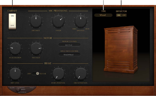
Chapter 15 Vintage B3 405
Advanced Cabinet parameters
The advanced cabinet parameters are divided into three groups: Cabinet, Motor, and Brake. Also
see Advanced Motor parameters and Advanced Brake parameters.
The microphone parameters are described in Vintage B3 Microphone parameters on page 409.
Deflector switchType pop-up menu
Cabinet switch
Cabinet parameters
•Cabinet switch: Turns the Leslie cabinet emulation on or o.
•Type pop-up menu: Choose a cabinet model:
•Real Cabinet: Uses an impulse response recording of a Leslie cabinet. Click the microphones
to change the type of microphone.
•Wood: Mimics a Leslie with a wooden enclosure, and sounds like the Leslie 122 or 147 model.
•Proline: Mimics a Leslie with a more open enclosure, similar to a Leslie 760 model.
•Single: Simulates the sound of a Leslie with a single, full-range rotor. The sound resembles
the Leslie 825 model.
•Split: The bass rotor’s signal is routed slightly to the left, and the treble rotor’s signal is routed
more toward the right.
•Wood & Horn IR: Uses an impulse response of a Leslie with a wooden enclosure.
•Proline & Horn IR: Uses an impulse response of a Leslie with a more open enclosure.
•Split & Horn IR: Uses an impulse response of a Leslie with the bass rotor signal routed slightly
to the left, and the treble rotor signal routed more to the right.
•Deector switch: Emulates a Leslie cabinet with the horn deectors removed or attached.
A Leslie cabinet contains a double horn, with a deector at the horn mouth. This deector
makes the Leslie sound. You can remove the deector to increase amplitude modulation and
decrease frequency modulation.
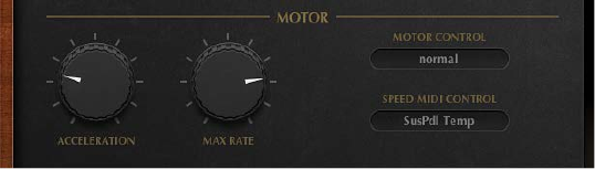
Chapter 15 Vintage B3 406
Advanced Motor parameters
The advanced cabinet parameters are divided into three groups: Cabinet, Motor, and Brake. See
also Advanced Cabinet parameters and Advanced Brake parameters.
The microphone parameters are described in Vintage B3 Microphone parameters on page 409.
Motor parameters
•Acceleration knob: Rotate to set the time it takes to get the rotors up to the speed set with
the Max Rate knob, and the length of time it takes for them to slow down. The Leslie motors
need to physically accelerate and decelerate the speaker horns in the cabinets, and their
power to do so is limited. Turn Acceleration to the far left position to switch to the preset
speed immediately. As you rotate the knob to the right, it takes more time to hear the speed
changes. At the default, centered, position the behavior is Leslie-like.
•Max Rate knob: Rotate to set the maximum possible rotor speed.
•Motor Control pop-up menu: Set dierent speeds for the bass and treble rotors in the pop-up
menu. Use the Rotation switch to choose slow, brake, or fast mode. See Vintage B3 Rotor
Cabinet window overview.
•Normal: Both rotors use the speed determined by the Rotation switch position.
•Inv (inverse): In fast mode, the bass compartment rotates at a fast speed, while the horn
compartment rotates slowly. This is reversed in slow mode. In brake mode, both rotors stop.
•910: The 910 (also known as “Memphis”), stops the bass drum rotation at slow speed, while
the speed of the horn compartment can be switched. This is useful when you’re after a solid
bass sound but still want treble movement.
•Sync: The acceleration and deceleration of the horn and bass drums are roughly the same.
This sounds as if the two drums are locked, but the eect is clearly audible only during
acceleration or deceleration.
Note: If you choose Single Cabinet from the (Cabinet) Type pop-up menu, the Motor Control
setting is not relevant because there are no separate bass and treble rotors in a single cabinet.
•Speed MIDI Control pop-up menu: Choose a MIDI controller that is used to remotely switch the
rotor speed. All items (except ModWheel) in the pop-up menu switch between fast and the
speed set with the Rotation switch positions—either switching between slow and fast, or
switching between brake and fast. If fast is chosen, the rotor speaker switches between fast
and slow.
•Modwheel: Assigns the modulation wheel to switch between all three speed settings. Brake
is selected around the modulation wheel’s center position, slow is selected in the lower third,
and fast in the upper third of the modulation wheel’s travel.
•Modwhl Toggle: Switches as soon as the modulation wheel moves away from the centered
position. If the modulation wheel passes the center position when moved from a high to
low position, no switching occurs. This caters to Roland keyboards with combined pitch
bend and modulation controls.
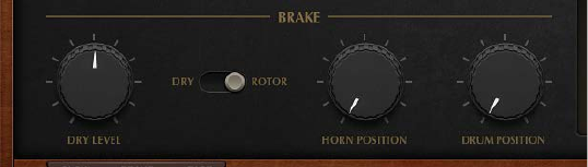
Chapter 15 Vintage B3 407
•Modwhl Temp: Switches as soon as the modulation wheel passes the center position,
regardless of whether you have moved the modulation wheel from high to low or from
low to high positions. This caters to Roland keyboards with combined pitch bend and
modulation controls.
•Touch: Switches with aftertouch on messages. No switching occurs on aftertouch release.
•Touch Temp: Switches with aftertouch on messages. A second switch occurs with aftertouch
release messages.
•SusPdl Toggle: Switches when you press the sustain pedal. No switching occurs when the
sustain pedal is released.
•SusPdl Temp: Switches when you press the sustain pedal. A second switch occurs when you
release the sustain pedal.
•CC #18 and CC #19 Toggle: Switches when you press controller 18 or 19. No switching occurs
when either controller is released.
•CC #18 and CC #19 Temp: Switches when you press controller 18 or 19. A second switch occurs
when you release controller 18 or 19.
Advanced Brake parameters
The advanced cabinet parameters are divided into three groups: Cabinet, Motor, and Brake. See
also Advanced Cabinet parameters and Advanced Motor parameters.
The microphone parameters are described in Vintage B3 Microphone parameters on page 409.
Brake parameters
•Dry Level knob: Rotate to set the level of the dry signal, which can also be useful if Dry is active
for the Output switch.
•Output switch: Choose one of two positions that modify Vintage B3 brake mode.
•Dry: The rotor cabinet is bypassed when stopped, with a delay time of one second. This is
useful when you are using the modulation wheel to switch between fast and slow rotor
speeds. If you then switch to brake mode, the rotors are slowed down during the transition
to the dry sound.
•Rotor: The movement of the rotor is gradually slowed down to a total stop.
•Horn/Drum Position knobs: Rotate to set an exact stop position for the Leslie horn or drum
(bass) rotator, respectively. The original Leslie did not provide this type of control. This
occasionally resulted in a horn aimed at the back of the cabinet when it came to a halt,
leading to a mued sound.
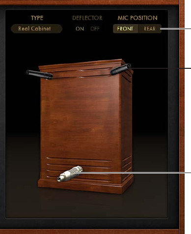
Chapter 15 Vintage B3 408
Vintage B3 Microphone types
Vintage B3 provides modeled microphones that pick up the sound of the Leslie cabinet. You can
specify the microphone type with these parameters.
Click to choose a
microphone type.
Click to choose a
microphone type.
Mic Position switch
Click the microphone icons to choose a microphone type for the horn and drum speakers when
Real Cabinet is chosen in the Type pop-up menu. See Advanced Cabinet parameters.
•Dynamic: Emulates the sound of a dynamic cardioid microphone. This microphone type
sounds brighter and more cutting than the Condenser mic.
•Condenser: Emulates the sound of a studio condenser microphone. The sound of condenser
microphones is ne, transparent, and well-balanced.
•Mid-Side Mic: A Middle and Side (MS) conguration where two microphones are positioned
closely together. One is a cardioid (or omnidirectional) microphone that directly faces the
cabinet—in a straight alignment. The other is a bidirectional microphone, with its axes
pointing to the left and right of the cabinet at 90° angles. The cardioid microphone captures
the middle signal to one stereo side. The bidirectional microphone captures the side signal to
the other stereo side.
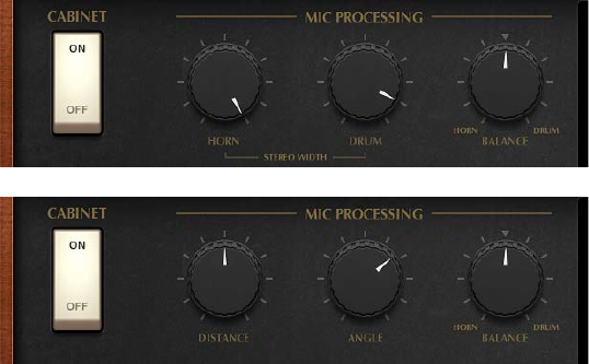
Chapter 15 Vintage B3 409
Vintage B3 Microphone parameters
Vintage B3 provides modeled microphones that pick up the sound of the Leslie cabinet. You can
set the listening position with these parameters.
Microphone parameters
•Mic Position switch: Choose either the front or rear position for the virtual microphone.
•When Real Cabinet is chosen in the Type pop-up menu:
•Horn knob: Rotate to dene the stereo width of the Horn deector microphone.
•Drum knob: Rotate to dene the stereo width of the Drum deector microphone.
•When other cabinets are chosen in the Type pop-up menu:
•Distance knob: Rotate to determine the distance of the virtual microphones (the listening
position) from the emulated speaker cabinet. Turn to the right for a darker and less
dened sound.
•Angle knob: Rotate to dene the stereo image, by changing the angle of the simulated
microphones between 0 and 180 degrees.
•Balance knob: Rotate to set the balance between the horn and drum microphone signals.
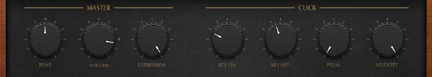
Chapter 15 Vintage B3 410
Vintage B3 Options window
Vintage B3 Options window overview
You can adjust the Vintage B3 output level, tuning, key click volume, and other basic sound
aspects with the Options controls. See Vintage B3 Master and Click controls.
Advanced controls for Percussion, Scanner Vibrato, and Morph are also found in the Options
window. See Vintage B3 Percussion eect, Vintage B3 Scanner Vibrato and Chorus, and Vintage
B3 Morph parameters.
The Edit Preset Key parameter is discussed in Switch Vintage B3 registrations with a two-draw
bar controller.
Vintage B3 Master and Click controls
Master parameters
•Tune knob: Rotate to change Vintage B3 tuning in cents. A cent is 1/100th of a semitone. 0 c is
equal to A=440 Hz.
•Volume knob: Rotate to set the overall output level. The Volume knob must be lowered
whenever crackling or other digital distortion occurs. Volume levels over 0 dB can occur if you
maximize the levels of all registers, play numerous notes, and make use of the Distortion eect.
•Expression knob: Rotate to set the sensitivity for a connected expression pedal (on a MIDI
keyboard with an Expression or assignable controller input). Extensive, often rhythmic, use of
the expression (volume) pedal forms part of the style of many organ players. The expression
control also emulates the tonal changes of the B3 pre-amplier, where bass and treble
frequencies are not attenuated as much as the mid frequencies. Your master keyboard should
transmit MIDI control change #11 when the pedal is moved. Vintage B3 defaults to the use of
CC #11 for Expression.
Click parameters
Advanced click controls are available in the Expert page. See Vintage B3 Condition controls.
•Key On/Key O knobs: Rotate to set the level of the key click sound heard during note on or
note o messages.
•Pedal knob: Rotate to set the level of the key click sound heard during note on and note o
messages for the pedal register.
•Velocity knob: Rotate to set the velocity sensitivity of the click parameters.
Chapter 15 Vintage B3 411
Vintage B3 Morph parameters
You can switch—or smoothly crossfade (morph)—between the presets of the upper manual. See
Use Vintage B3 Morph controls.
Important: Morph controls are spread across two windows. Click Main in the control bar, then
click the Preset button at the lower right to view the Morph slider. The Options window contains
advanced Morph controls.
Morph parameters
•Upper Morph slider (Main window): Drag left or right to control the switching or morphing. You
can also assign and use a MIDI controller such as your keyboard modulation wheel to control
the Morph slider.
•Select via Keyboard buttons (Main window): Click the On button, then play a lower and upper
key to set the range of Preset keys aected by the morph. Click O to disable the morph range
set up.
•Mode switch (Options window): Click Step to abruptly switch, or click Linear to smoothly morph
(crossfade) between presets.
•Range pop-up menu (Options window): Choose a range of keys for morph presets.
•MIDI Controller pop-up menu (Options window): Assigns a MIDI controller to the Morph slider.
You can choose any MIDI controller number shown (or channel aftertouch). You can also click
Learn to teach the Morph slider to respond to any incoming message.
Chapter 15 Vintage B3 412
Use Vintage B3 Morph controls
You can switch—or smoothly crossfade (morph)—between the presets of the upper manual. See
Vintage B3 Morph parameters.
Important: Morph controls are spread across two windows. Click Main in the control bar, then
click the Preset button at the lower right to view the Morph slider. The Options window contains
advanced Morph controls.
Learn a MIDI controller for morphing
1 Click Options in the control bar.
2 Choose Learn from the (Morph) MIDI Controller pop-up menu.
When Learn is active, the parameter is assigned to the rst appropriate incoming MIDI data
message.
3 Move the MIDI controller on your MIDI device.
Learn mode has a 20-second time-out function: if Vintage B3 does not receive a MIDI message
within 20 seconds, the parameter reverts to its original MIDI controller assignment.
Set the Vintage B3 morph range
Once you have chosen a controller to use for switching or morphing between upper manual
registrations, you can determine the number of preset keys that are aected. You can morph
between two and eleven presets for the upper manual.
Morphing always begins with the top preset key, the B.
•If Range = A#, you morph between two presets.
•If Range = G#, you morph between four presets (B, A#, A, and G).
•If Range = F#, you morph between six presets (and so on).
1 Click Main in the control bar.
2 Click the Preset button at the lower right.
3 Click the Select via Keyboard On button.
4 Play two keys on your MIDI keyboard to set the morph range.
Save a registration while morphing
In Linear mode (morphing), the seamless crossfades result in a variety of new draw bar
registrations that you might want to save. You can change draw bar positions manually, before
saving.
mClick View > Controls, then choose a preset key from the “Save Morph to” pop-up menu (near the
bottom of the Preset parameters).
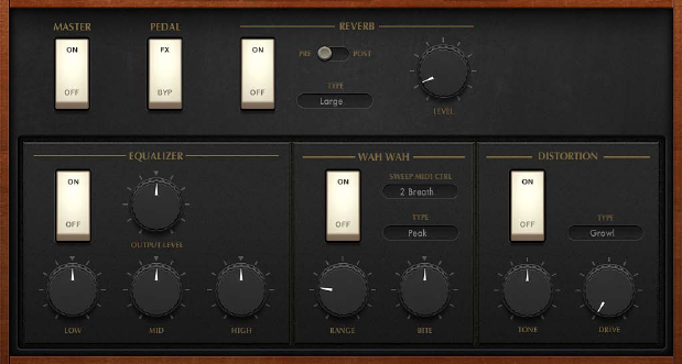
Chapter 15 Vintage B3 413
Vintage B3 Eects window
Use Vintage B3 eects
Vintage B3 features a three-band equalizer, a reverberation eect, a pedal-controllable wah wah
eect, and a distortion eect that simulates the sound of an overdriven tube amplier. In
addition, the signal can be routed through the Leslie rotor speaker emulation.
The default eect signal ow is as follows: the organ’s signal runs through the Equalizer, Wah, and
Distortion eects. This treated signal is then fed into the Reverb, and nally passed to the Leslie
rotor eect.
Activate or bypass the eects
Do one of the following:
mTurn the Master switch on or o to enable or disable the entire Vintage B3 eects section.
mUse the On/O switches to independently enable or disable the Reverb, EQ, Wah, and
Distortion eects.
Change the routing of the EQ, Wah, and Distortion eects.
mDrag the name of each eect to create the signal ow you require.
•EQ-Wah-Dist: This routing is perfect for a classic B3 patch—an equalized organ, plugged into a
wah pedal, amplied by an overdriven Leslie.
•EQ-Dist-Wah: The sound of the overdrive changes if the input signal is being ltered, either
by the EQ or the Wah. Placing the EQ before the Distortion provides further sonic exibility.
Although the output signal of the Distortion eect always contains high frequency content,
this content can be suppressed by positioning the Wah as the nal eect in the chain.
•Wah-Dist-EQ: If you want to create a screaming sound (achieved by distorting the Wah eect
output), you can minimize any harshness by choosing this routing.
•Dist-EQ-Wah: Choose this routing to suppress the harsh overtones of extreme distortions with
two lters.
Chapter 15 Vintage B3 414
Bypass eects for the pedal register
mSet the Pedal switch to Byp. If you choose FX, the entire output of the organ is processed.
Bypassing the Distortion, Wah, and EQ eects separately for the pedal register avoids suppression
of the bass portion of your organ sound by the Wah eect. It also avoids intermodulation
artifacts when the Distortion eect is used.
Vintage B3 EQ
Vintage B3 features a simple but eective EQ section.
Vintage B3 EQ parameters
•EQ On/O switch: Turn on or bypass the equalizer.
•Output Level knob: Rotate to adjust the overall EQ level.
•Low knob: Rotate to adjust the level of the low frequency range.
•Mid knob: Rotate to adjust the level of the mid frequency range.
•High knob: Rotate to adjust the level of the high frequency range.
Vintage B3 Wah eect
The name wah wah comes from the sound it produces. It has been a popular eect with electric
guitarists since the days of Jimi Hendrix. The pedal controls the cuto frequency of a bandpass,
lowpass, or—less commonly—highpass lter. The wah pedal is also used extensively with the
Hammond organ.
For the most dynamic and musical performance of the Wah eect, consider attaching an
expression pedal to your MIDI master keyboard. Your master keyboard should transmit MIDI
control change #11, which would normally be used to control Vintage B3 volume while playing.
Vintage B3 Wah parameters
•Wah On/O switch: Turn on or bypass the Wah eect.
•Sweep MIDI Ctrl pop-up menu: Use to assign a MIDI controller to the Wah eect.
•Type pop-up menu: Choose one of several Wah eect types.
•Classic Wah: This setting mimics the sound of a popular wah pedal with a slight
peak characteristic.
•Retro Wah: This setting mimics the sound of a popular vintage wah pedal.
•Modern Wah: This setting mimics the sound of a distortion wah pedal with a constant
Q(uality) Factor setting. The Q determines the resonant characteristics. Low Q values aect
a wider frequency range, resulting in softer resonances. High Q values aect a narrower
frequency range, resulting in more pronounced emphasis.
•Opto Wah 1: This setting mimics the sound of a distortion wah pedal with a constant
Q(uality) Factor setting.
•Opto Wah 2: This setting mimics the sound of a distortion wah pedal with a constant
Q(uality) Factor setting.
•Resonant LP: In this mode, the Wah works as a resonance-capable lowpass lter. At the
minimum pedal position, only low frequencies can pass.
•Resonant HP: In this mode, the Wah works as a resonance-capable highpass lter. At the
maximum pedal position, only high frequencies can pass.
•Peak: In this mode, the Wah works as a peak (bell) lter. Frequencies close to the cuto
frequency are emphasized.
Chapter 15 Vintage B3 415
•Range knob: Rotate to determine the sensitivity of the Wah eect to incoming MIDI
controller data.
•Bite knob: Rotate to boost the levels of signals surrounding the cuto frequency. Bite is
eectively a lter resonance parameter, where high values makes the Wah eect sound
more aggressive.
Use an expression pedal to control the Wah eect
1 Click Options in the control bar, then set the Expression knob to a value of 0.
2 Click Eects in the control bar, then choose controller 11 from the Sweep MIDI Control
pop-up menu.
This enables control of the Wah’s cuto frequency with the expression pedal and requires no
further setup of your master keyboard. If step 1 is overlooked, the expression pedal is used to
control both Vintage B3 main volume and the Wah eect.
Note: Consult the user manual for your keyboard to learn more about use of an
expression pedal.
3 Adjust the Range knob to set the sensitivity of the Wah to incoming expression pedal
controller data.
Learn a MIDI controller to control the Wah eect
1 Click Eects in the control bar.
2 Choose Learn from the Sweep MIDI Ctrl pop-up menu.
When Learn is active, the parameter is assigned to the rst appropriate incoming MIDI data
message.
3 Move the MIDI controller on your MIDI device.
Learn mode has a 20-second time-out facility: if Vintage B3 does not receive a MIDI message
within 20 seconds, the parameter reverts to its original MIDI controller assignment.
Chapter 15 Vintage B3 416
Vintage B3 Distortion eect
The Distortion eect simulates an overdriven two-stage tube amplier. Its primary role is to
simulate the Leslie amplier or another amplier used to feed the Leslie speaker cabinet.
Vintage B3 Distortion parameters
•Distortion On/O switch: Turn on or bypass the Distortion eect.
•Type pop-up menu: Choose a tube amplier model.
•Growl: Simulates a two-stage tube amplier. It closely resembles the Leslie 122 model, the
classic partner for the Hammond B3 organ.
•Bity: Reminiscent of a bluesy guitar amp.
•Nasty: Delivers hard distortions and is suitable for very aggressive sounds.
•6550 AB V3: Tube distortion sound modeled on class AB amp head.
•6550 AB V2: Tube distortion sound modeled on class AB amp head.
•6550 GL: Tube distortion sound modeled on tube amp head.
•Tone knob: Rotate to change the distorted portion of the sound. This has no eect on the
dry signal portion. Limiting changes to the distorted signal allows for very warm overdriven
sounds that do not become scratchy if you try to get more treble out of Vintage B3.
•Drive knob: Rotate to set the amount of overdrive distortion. The output level is automatically
compensated for, so there’s no need for a distortion output volume control. A level of 0
eectively turns o the Distortion circuit.
Note: The Drive knob shown in the Main window is linked with the Drive knob shown in
the Eects window. When you rotate either Drive knob, your change is mirrored in the other
window. In essence, this is a convenience feature that addresses the same parameter in
both locations.
Vintage B3 Reverb eect
Vintage B3 features a simple reverberation eect that emulates several room types and a
spring reverb.
Vintage B3 Reverb parameters
•Reverb On/O switch: Turn on or bypass the reverb eect.
•Pre/Post switch: Patches the reverb eect before (Pre) or after (Post) the rotor eect. The
reverb is always patched after the EQ, Wah, and Distortion eects, but before the Leslie rotor
cabinet. Switch to Post if you don’t want the reverb to sound like it is played back through the
rotor speaker.
•Type pop-up menu: Choose from six reverb algorithms: Air, Box, Small, Medium, Large, Big,
and Spring.
•Level knob: Rotate to set the balance between the reverb and original signal levels.
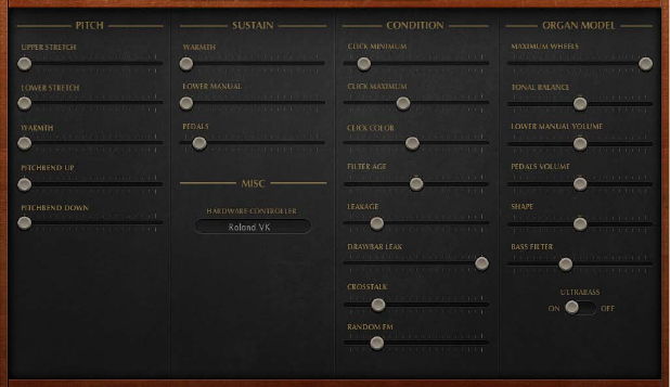
Chapter 15 Vintage B3 417
Vintage B3 Expert window
Vintage B3 Expert window overview
The Expert window shows model parameters that provide precise control over your organ sound.
These include not only basic level and tonal balance controls, but a number of parameters that
emulate the sonic characteristics—and technical “aws” or limitations—of the original Hammond
B3. You can even emulate the quirks of the B3 by aging the virtual components. See Vintage B3
Pitch controls, Vintage B3 Sustain controls, Vintage B3 Condition controls, and Vintage B3 Organ
Model controls.
See Choose a Vintage B3 MIDI control mode for information on the Hardware Controller
parameter shown in the Misc section of the Expert window.
For more information about the technical aspects of the Hammond B3 and the concepts behind
tonewheel sound generation, see A brief Hammond history on page 430 and Tonewheel sound
generation on page 429.
Chapter 15 Vintage B3 418
Vintage B3 Pitch controls
Vintage B3 provides several parameters that change its pitch behavior, adding exibility that isn’t
possible with the original instrument.
Vintage B3 is tuned to an equal-tempered scale. As a deviation from this standard tuning, you
can stretch the tuning in the bass and treble ranges, much like acoustic pianos (especially
upright pianos). The tones of clavinets, harpsichords, and pianos have inharmonicities in their
harmonic structure. The frequencies of these overtones (harmonics) are not exact, whole-number
multiples of the base frequency. This means that the overtones of lower (tuned) notes are
more closely related to the main frequencies of the upper notes. Due to the lack of strings, this
inharmonic relationship is not true of organs. The stretch feature was principally included for
situations in which you want to use Vintage B3 in an arrangement alongside a recording of an
acoustic piano.
You can also randomly detune the sound using the Warmth parameter, and you can even use the
pitch bend wheel of your keyboard to bend the sound. The latter isn’t true to the original, but it’s
a nice creative option.
Pitch parameters
•Upper Stretch slider: Drag to set the amount of deviation from the equal-tempered scale in
the treble end of the sound. The higher the value, the further up the high notes are tuned. At
a setting of 0, Vintage B3 is tuned to an equal-tempered scale, with each octave up exactly
doubling the frequency.
•Lower Stretch slider: Drag to set the amount of deviation from the equal-tempered scale in the
bass frequencies. The higher the value, the further down the low notes are tuned. At a setting
of 0, Vintage B3 is tuned to an equal-tempered scale, with each octave below exactly halving
the frequency.
•Warmth slider: Drag to set the amount of random deviation from an equal-tempered scale.
Note: Use of both Warmth and Stretch may result in a detuned sound, which is similar to a
heavy chorus eect. Set Warmth to 0 if you’re after a purer sound.
•Pitchbend Up/Down sliders: Drag to independently set the pitch bend up/down sensitivity in
semitone steps. The maximum sensitivity for upward bends is one octave. The Hammond
B3 has no pitch bend facilities. Therefore, use of pitch bend is not suitable for realistic organ
simulations, but it does provide a number of creative options.
Note: If you drag the Pitchbend Down slider to the far right, the tonewheels gradually slow
down until they totally stop—when your keyboard’s pitch bend control is at the minimum
position. This setting re-creates an eect heard at the end of “Knife Edge” by Emerson, Lake,
and Palmer. Keith Emerson’s virtuoso Hammond work was recorded on a reel-to-reel tape
recorder that was gently slowed to a total stop.
Chapter 15 Vintage B3 419
Vintage B3 Sustain controls
The time it takes for a note to fade out to silence, after the key has been released, is called the
release time in synthesizers. Vintage B3 provides control of this parameter, known as sustain in
organ terminology.
Sustain parameters
•Upper Manual slider: Drag to control the sustain (release) phase of the upper register.
•Lower Manual slider: Drag to control the sustain (release) phase of the lower register.
•Pedals slider: Drag to control the sustain (release) phase of the pedal register.
•Mode buttons (Controls view only): Click to choose one of two sustain behaviors:
•Smart: Cuts the sustain phase of released notes when you play new notes.
•Normal: Allows polyphonic sustain phases. All released notes will continue to sustain, even if
new notes are played.
Note: Smart mode allows for long sustain times, even in the bass register, which would cause
rumbling dissonances if you used normal mode.
Vintage B3 Condition controls
Technical limitations of electromechanical draw bar organs, with tonewheels, can cause some
strange tonal artifacts, such as crosstalk. These quirks form an integral part of the B3’s charm. You
can adjust a number of parameters to dene the age and condition of your Vintage B3.
The key contacts of electromechanical tonewheel organs tend to saw a little on the busbar, thus
introducing a short click sound. Corrosion of the key contacts or busbar increases the length and
level of this click. This aspect of the B3’s design causes irregular scratching noises (commonly
referred to as key click) when striking and releasing keys. Hammond fans like these clicking noises
because they introduce a transient, percussive quality to the note.
Vintage B3 allows you to adjust the volume and sound of the key click. The tonal color and
volume of clicks are altered randomly, and independently, from the click on and click o (release)
volume settings.
Condition parameters
•Click Minimum/Maximum sliders: Combined, these sliders determine a range for click duration,
which can vary between a short “tick” and a longer “scratch.” A random click duration (that falls
within the dened range) is used as you play.
Note: Even if both parameters have identical values, there is a random variation in sound that
makes some clicks seem shorter than the value set with Click Min.
•Click Color slider: Drag to set the tonal color of the click. This acts as a global control for the
treble portion of the click sound, which overrides (but works alongside) the random click
color variations.
•Filter Age slider: Drag to set the center frequencies of the lters, which emulates aging
capacitors. The high frequency output signals of the B3’s tonewheel generators are passed
through bandpass lters. The center frequency of these lters changes as the capacitors (used
for ltering) get older.
Note: This colors the sound of the jitter applied by Random FM and the background noise
resulting from leakage. Filter Age also inuences the intonation of the organ, if you use a
pitch bend.
Chapter 15 Vintage B3 420
•Leakage slider: Drag to add a sound resulting from the crosstalk between all tonewheels—
including the tonewheels of notes that you don’t play. Adjust this slider to add a “breathy”
quality to your organ sound.
•Drawbar Leak slider: Drag to set the minimum output level of the draw bars when they are
at their minimum positions. The B3 tonewheel generators aren’t completely quiet, even if all
draw bars are at their minimum positions. This is due to leakage of the tonewheels, causing
crosstalk at the output.
•Use the minimum setting to completely eliminate draw bar leakage.
•Use the maximum setting to make draw bar leakage clearly audible.
•Crosstalk slider: Drag to set the crosstalk level. There are two tonewheels that are four
octaves apart for each key (pitch), on each rotating shaft. The signal of the lower wheel has
a small amount of audible crosstalk, induced by the higher wheel, and vice versa. For more
information, see Tonewheel sound generation on page 429. Because crosstalk is audible only
on certain B3 tonewheels, any “rumble” when chords are played is avoided.
•Random FM slider: Drag to simulate irregular rotation of tonewheels in an old B3. If the
tonewheel generator of a B3 is clean, all frequencies are even and in tune. The three-fold
decoupling of the tonewheels—via springs, exible couplings, and ywheels—is eective,
but it can’t compensate for irregularities that come with dirt and grease in the driving gears.
A gradual build-up of grime in the mechanism makes the tonewheel assembly turn unevenly
on its axis. This irregular rotation is transmitted to the tonewheels, and therefore, the higher
frequency ranges of the sound.
Chapter 15 Vintage B3 421
Vintage B3 Organ Model controls
The Organ Model controls change the basic tonal quality.
Organ Model parameters
•Maximum Wheels slider: Drag to set the number of tonewheels that are emulated. Reduce
the value to minimize the computer processing load. Reducing the value diminishes some
overtones, so keep the number high if you’re after an ultrarealistic simulation.
•Tonal Balance slider: Drag to change the mix relationship of the higher and lower tonewheels.
Use positive values to achieve a lighter and brighter sound. Experiment with dierent tonal
balance and equalizer settings. See Vintage B3 EQ on page 414, for further information.
•Lower Manual Volume slider: Drag to set relative levels between the upper and lower manuals
(and pedalboard).
•Pedals Volume slider: Drag to set relative levels between the upper (and lower) manual and
the pedalboard.
•Shape slider: Drag to alter the waveforms of the tonewheel generator, allowing you to produce
sounds that resemble the tones of Farsa, Solina, or Yamaha organs. The Hammond’s tone
generators produce pure sine waves (albeit with a few artifacts), whereas some other organs
deliver distorted waveforms. The Shape parameter is placed after the lters that follow the
sine generators.
•Move the Shape slider to the right to make the tone brighter (and louder).
•Move the Shape slider to the left to make the tone duller (and softer).
•Bass Filter slider: The tone of the pedal draw bars can sound bright, within the context of the
combined upper/lower/pedal sound. Adjust to circumvent this issue, and to suppress the
treble of the bass register. At the maximum position you will only hear a solid bass organ
fundamental in the bass register.
•Ultrabass switch: Turn on to add another low octave to the playable range of both the upper
and lower manuals.These additional low octaves, and the ability to independently transpose
both manuals (see Transpose keyboard zones by octaves on page 402), are not available on
the original B3.

Chapter 15 Vintage B3 422
Use a MIDI controller with Vintage B3
Choose a Vintage B3 MIDI control mode
MIDI controller assignments allow you to control Vintage B3 with an external MIDI controller or a
host application such as Logic Pro.
The Hardware Controller parameter determines the way Vintage B3 draw bars respond to remote
MIDI control change messages. Most users won’t need to change anything here.
If you own a MIDI draw bar organ, you’ll want to use its hardware draw bars to control Vintage
B3. Most hardware draw bar organs use an independent MIDI control change number for each
draw bar.
Choose a MIDI hardware controller
1 Click Expert in the control bar.
2 Choose a device (mode) from the Hardware Controller pop-up menu. Choose O if you do not
own a supported device and don’t want to use a special assignment mode.
•Choose Vintage B3 MIDI mode: Roland VK or Korg CX if you use a Roland VK series or Korg
CX-3 draw bar organ as a remote controller for Vintage B3.
•Choose Vintage B3 MIDI mode: Hammond Suzuki if you use a Hammond XB series organ as a
remote controller for Vintage B3.
•Choose Vintage B3 MIDI mode: Native Instruments B4D if you use a Native Instruments B4D
remote controller for Vintage B3.
•Choose Vintage B3 MIDI mode: Nord Electro if you use a Clavia Nord Electro 2 as a remote
controller for Vintage B3.
Vintage B3 MIDI mode: Roland VK or Korg CX
This table shows the MIDI controller assignments when MIDI mode is set to Roland VK or Korg
CX. Choose either setting if you use a Roland VK series or Korg CX-3 draw bar organ as a remote
controller for Vintage B3.
Controller number MIDI mode VK or CX: assigned parameter
70 draw bar 16'
71 draw bar 5 1/3'
72 draw bar 8'
73 draw bar 4'
74 draw bar 2 2/3'
75 draw bar 2'
76 draw bar 1 3/5'
77 draw bar 1 1/3'
78 draw bar 1'
Rotor Cabinet
80, 92 Slow/Brake/Fast
81 Slow/Brake
Reverb
82 Reverb Level

Chapter 15 Vintage B3 423
Controller number MIDI mode VK or CX: assigned parameter
Vibrato
85 Upper Vibrato on/o
86 Lower Vibrato on/o
87 Chorus Vibrato Type
Percussion
94 on/o
95 2nd/3rd
102 Percussion Volume
103 Percussion Time
Equalizer
104 EQ Low
105 EQ Mid
106 EQ Hi
107 EQ Level
Wah
108 Wah Mode
109 Wah Bite
Distortion
110 Distortion Type
111 Distortion Drive
112 Distortion Tone
Click Levels
113 Click On Level
114 Click O Level
Balance
115 Main Volume
116 Lower Volume
117 Pedal Volume
Rotor Fast Rate
118 Rotor Fast Rate

Chapter 15 Vintage B3 424
Vintage B3 MIDI mode: Hammond Suzuki
This tables shows the MIDI controller assignments when MIDI mode is set to Hammond Suzuki.
This setting matches the controller mapping of Hammond XB-series organs.
Controller number MIDI mode Hammond Suzuki: assigned parameter
80 All upper draw bars
81 All lower draw bars
82 Pedal draw bars, Scanner Vibrato, Bass Filter
Rotor Cabinet
Leslie On Rotor Cabinet on/o
Leslie Fast Slow/Brake
Leslie Brake Controls Brake function of Rotor Cabinet
Vibrato
Vibrato On Upper Vibrato on/o (on XK-3 only)
Vibrato Mode Vibrato type (V1-C3, XK-3 only)
87 Chorus Vibrato type
Drive Distortion Drive
Reverb Level Reverb Level
Perc 2nd and Perc 3rd Percussion Harmonic, 3rd harmonic has priority over
2nd. Translation from XK buttons to Vintage B3 is as
follows:
•2nd o, 3rd o x Vintage B3: Percussion o
•2nd on, 3rd o x Vintage B3: 2nd Harmonic
•2nd o, 3rd on x Vintage B3: 3rd Harmonic
•2nd on, 3rd on x Vintage B3: 3rd Harmonic
Perc Fast Selects a preset decay time for fast or slow decay
Perc Soft Selects a preset level for either soft or normal
percussion
Vibrato Mode Selects either Vibrato O, V1/V2/V3, or C1/C2/C3 (XK-2
only)
Vibrato VC Switches between Vibrato or Chorus Vibrato (XK-2
only)

Chapter 15 Vintage B3 425
Vintage B3 MIDI mode: Native Instruments B4D
This table shows the MIDI controller assignments when MIDI mode is set to Native Instruments
B4D. This setting matches the controller mapping of the Native Instruments B4D controller.
Controller number MIDI mode Native Instruments B4D: assigned
parameter
12 Upper draw bar 16'
13 Upper draw bar 5 1/3'
14 Upper draw bar 8'
15 Upper draw bar 4'
16 Upper draw bar 2 2/3'
17 Upper draw bar 2'
18 Upper draw bar 1 3/5'
19 Upper draw bar 1 1/3'
20 Upper draw bar 1'
21 Lower draw bar 16'
22 Lower draw bar 5 1/3'
23 Lower draw bar 8'
24 Lower draw bar 4'
25 Lower draw bar 2 2/3'
26 Lower draw bar 2'
27 Lower draw bar 1 3/5'
28 Lower draw bar 1 1/3'
29 Lower draw bar 1'
Vibrato
31 Upper Vibrato on/o
30 Lower Vibrato on/o
Brightness Vibrato
Attack Time Chorus Intensity
Percussion
Sostenuto Percussion on/o
Release Time Percussion Harmonic (2nd/3rd)
Sound Variation Percussion Volume
Harmonic Content Percussion Time
Equalizer
90 EQ Low
70 EQ Mid
5 EQ High
Distortion/Click
76 Distortion Drive

Chapter 15 Vintage B3 426
Controller number MIDI mode Native Instruments B4D: assigned
parameter
78 Distortion Tone
75 Click On Level
Leslie
Pan MSB Microphone Angle
3 Microphone Distance
GP 8 Leslie Accelerate/Decelerate
GP 7 Leslie Fast
ModWheel MSB Leslie Speed
68 Controls Brake function: if Value = 0.0, switches Leslie
to Brake. All other values switch Leslie to previous
speed.

Chapter 15 Vintage B3 427
Vintage B3 MIDI mode: Nord Electro
This table shows the MIDI Control Change Message number assignment when MIDI mode is set
to Nord Electro. This setting matches the controller mapping of the Clavia Nord Electro 2.
Controller number MIDI mode Nord Electro: assigned parameter
16 Upper draw bar 16'
17 Upper draw bar 5 1/3'
18 Upper draw bar 8'
19 Upper draw bar 4'
20 Upper draw bar 2 2/3'
21 Upper draw bar 2'
22 Upper draw bar 1 3/5'
23 Upper draw bar 1 1/3'
24 Upper draw bar 1'
70 Lower draw bar 16'
71 Lower draw bar 5 1/3'
72 Lower draw bar 8'
73 Lower draw bar 4'
74 Lower draw bar 2 2/3'
75 Lower draw bar 2'
76 Lower draw bar 1 3/5'
77 Lower draw bar 1 1/3'
78 Lower draw bar 1'
Chorus/Vibrato
85 Upper Vibrato on/o
86 Lower Vibrato on/o
84 Vibrato mode (selection goes from V1 to C3, C0 is
excluded)
Percussion
87 Percussion on/o
88 Percussion Volume (soft/normal) and Time (short/
long)
95 Percussion Harmonic (2nd/3rd)
Equalizer
113 EQ High
114 EQ Low
Distortion/Click
111 Distortion Drive
Leslie
GP 6 on/o
GP 7 Leslie Speed
GP 8 Controls Brake function
Chapter 15 Vintage B3 428
B3 and Leslie information
Additive synthesis with draw bars
The Hammond B3 is the classic draw bar organ. As with an air-driven pipe organ, the registers
(draw bars, or “stops” on a pipe organ) can be pulled out to engage them. In contrast to a pipe
organ, however, the B3 allows seamless mixing of any draw bar registers. The closer toward you
that the draw bars are dragged, the louder the corresponding tones.
Despite characteristics such as key clicks, variable intonation, distortions, and crosstalk (all of
which Vintage B3 emulates), playing a single note, with a single register, results in a pure sine
tone. Mixing sine tones results in more complex harmonic spectra; this is known as additive
synthesis. Organs—even pipe organs—can be regarded as additive synthesizers. Several
limitations should be considered before viewing the instrument in this way. These limitations, on
the other hand, constitute the charm and character of any real musical instrument.
The naming of the draw bars is derived from the length of organ pipes, measured in feet ('). This
naming convention is still used with electronic musical instruments.
•Halving the length of a pipe doubles its frequency.
•Doubling the frequency results in an upward transposition of one octave.
The lowest register—16' (far left, brown draw bar)—and the higher octave registers—8', 4', 2',
and 1' (white draw bars)—can be freely mixed, in any combination. 16' is commonly described
as the sub-octave. With the sub-octave regarded as the fundamental tone, or rst harmonic, the
octave above 8' is the second harmonic, 4' the fourth harmonic, 2' the eighth harmonic, and 1'
the sixteenth harmonic.
With the 5 1/3' register—the second brown draw bar—you can add the third harmonic. This
is the fth above the 8'. Basically, the draw bars are arranged by pitch, with one exception. The
second draw bar (5 1/3') sounds a fth higher than the third draw bar. See The residual eect on
page 429 for an explanation.
The 2 2/3' register generates the sixth harmonic, 1 3/5' the tenth harmonic, and 1 1/3' the
twelfth harmonic.
An electromechanical tonewheel organ oers the choice of the following registers/harmonics: 1
(16'), 2 (8'), 3 (5 1/3'), 4 (4'), 6 (2 2/3'), 8 (2'), 10 (1 3/5'), 12 (1 1/3'), and 16 (1'). As you can see, the
harmonic spectrum is nowhere near complete. This is one of the main reasons for the common
practice of using overdrive and distortion eects with electromechanical tonewheel organs—
they enrich the harmonic spectra by generating more harmonics.
Note: 2 2/3' is the fth over 4'. 1 3/5' is the major third over 2'. 1 1/3' is the fth over 2'. In the
bass range, this can lead to inharmonic tones, especially when playing bass lines in a minor key.
This is because mixing 2', 1 3/5', and 1 1/3' results in a major chord.
Chapter 15 Vintage B3 429
The residual eect
The residual eect is a psychoacoustic phenomenon. Human beings can perceive the pitch of
a note, even when the fundamental tone is completely missing. If you pull out all registers of a
draw bar organ, except for the fundamental—16'—you’ll still perceive the same pitch. The sound
becomes thinner, with less bass and less warmth, but the pitch remains the same.
If human beings didn’t hear this way, it would make listening to music on a small transistor radio
impossible. The tiny speaker of a small radio can’t accurately play back the fundamental tone of
the bass line because this frequency is far below the range that the speaker can reproduce.
Setting draw bar registrations often involves this psychoacoustic phenomenon. In the lower
octaves, mixing the 8' and 5 1/3' sine draw bars creates the illusion of a 16' sound, although the
lower frequency is missing.
Old pipe organs also make use of the residual eect, by combining two smaller pipes, thus
eliminating the need for long, heavy, and expensive giant pipes. This tradition is continued in
modern organs and is the reason for arranging the 5 1/3' under 8': the 5 1/3' tends to create the
illusion of a pitch that is one octave lower than 8'.
Tonewheel sound generation
Tonewheel sound generation resembles that of an air horn, or a siren. Of course, there’s no air
being blown through the holes of a revolving wheel. Rather, an electromagnetic pickup, much
like a guitar pickup, is used to capture the sound.
A notched metal wheel, called a tonewheel, revolves at the end of a magnetized rod. The teeth of
the wheel cause variations in the magnetic eld, inducing an electrical voltage. This voltage/tone
is then ltered, has vibrato and expression applied to it, and is then amplied.
An AC synchronous motor drives a long drive shaft. Twenty-four driving gears with 12 dierent
gear sizes are attached to the shaft. These gears drive the tonewheels. The frequency depends on
the gear ratios and the number of notches in the wheels. The Hammond is tuned to an (almost
exact) equal-tempered scale.
As with pipe organs that feature multiplexed registers, the Hammond organ uses certain
generators for more than one purpose. Some high frequency wheels serve as the fundamental
for high notes and provide harmonics for lower notes. This has a positive impact on the overall
organ sound, avoids detuning, and stabilizes levels between octaves.
Chapter 15 Vintage B3 430
A brief Hammond history
Three inventions inspired Laurens Hammond (1895–1973), a manufacturer of electric clocks, to
construct and market a compact electromechanical organ with tonewheel sound generation.
The Telharmonium by Thaddeus Cahill was the musical inspiration; Henry Ford’s mass production
methods and the domestic synchron clock motor were the other factors.
The Telharmonium (built around 1900) was the rst musical instrument that made use of
electromechanical sound generation techniques. Its immense tonewheel generators lled a
two-story building in New York. For a short period around this time, subscribers could order
Telharmonium music over the New York telephone network (the streaming audio system of
the time). The only amplication tool was the telephone’s mechanical diaphragm because a
proper tube amplier and acceptable speakers had not yet been invented. The Telharmonium
was a commercial op, but its historical status as the predecessor of modern electronic musical
instruments is undeniable. The Telharmonium also introduced the principles of electronic
additive synthesis (see Additive synthesis with draw bars on page 428).
Laurens Hammond began producing organs in 1935 in Chicago, Illinois, making use of the same
sound generation method. However, he used much smaller tone generators and fewer registers.
The patent for his model A organ dates from 1934.
Hammond also holds the patent for the electromechanical spring reverb, still found in countless
guitar ampliers today.
The Hammond B3 was manufactured between 1955 and 1974. It is the Hammond model
preferred by jazz and rock organ players, such as Fats Waller, Wild Bill Davis, Brother Jack McDu,
Jimmy Smith, Keith Emerson, Jon Lord, Brian Auger, Steve Winwood, Joey DeFrancesco, and
Barbara Dennerlein.
In addition to the B3, there are a number of smaller Hammond instruments, known as the
spinet series (M3, M100, L100, T100). Bigger console models, many of which were designed
to suit the needs of American churches or theaters (H100, X66, X77, E100, R100, G-100), were
also manufactured.
The production of electromechanical organs ceased in 1974. Thereafter, Hammond built fully
electronic organs.
The Hammond name lives on in the Hammond-Suzuki range of electronic draw bar organs,
starting with the 2002 release of a digital B3 model that mimics the design and functions of the
classic B3 (without the weight). This model, as well as newer units, can be partnered with real,
mechanical, rotor speaker cabinets, also from the company.
Chapter 15 Vintage B3 431
The Leslie cabinet
Don Leslie developed his rotor cabinets in 1937 and began marketing them in 1940. Laurens
Hammond wasn’t keen on the concept of rotating speakers at all.
Leslie’s approach was to simulate a variety of locations in the pipes (as in pipe organs), resulting
in a new spatial perception for every note. The rotor speaker cabinets could simulate this eect,
and the sense of space that they impart is incomparable, when placed side-by-side with any
xed speaker. The periodic undulations in sound and volume and the vibrato caused by the
Doppler eect (see below) aren’t all there is to the Leslie sound—it’s the spatial eect, too.
The “classic” Leslie speaker design features two drivers—a treble driver with horns (only one
works; the other simply acts as a counter-weight) and a bass driver. The horns of the treble driver
and the sound bae of the bass driver are physically rotated by electric motors.
Because the speakers rotate toward the front of the cabinet (the listening position), then toward
the back of the cabinet, you hear a “Doppler eect”—where sounds become louder and brighter
as their position changes. To give you an idea of this eect, it is much like the sound of a train
going past if you were standing on the platform. On approach, the sound is mued, but then it
becomes both louder and brighter as the train passes, and nally it becomes more mued as it
moves away from you.
The rotating driver/sound bae can be switched between two speeds—fast/Tremolo or slow/
Chorale (or stopped completely with a mechanical brake). The transition between the two
speeds, or the use of a xed speed, produces the characteristic “Leslie” vibrato, tremolo, and
chorus eects.
The rst Leslie, the model 30, had no Chorale—just tremolo and stop. The Chorale idea (which
came much later) was born of a desire to add a vibrato to the organ. Chorale, which oers far
more than a simple vibrato, was rst introduced to the market with the 122/147 models. At this
time, Leslie also added the “Voice of the pipe organ” label to his cabinets.
It wasn’t until 1980 that the two companies and brand names came together, six years after the
last tonewheel organ was built. Mechanical Leslie rotor cabinets are still being built today, by the
Hammond-Suzuki company.
432
Vintage Clav overview
Vintage Clav emulates the classic Hohner D6 Clavinet. The sound of the D6 is synonymous
with funk, but it was also popularized in the rock, pop, and electric jazz of the 1970s by artists
like Stevie Wonder, Herbie Hancock, Keith Emerson, Foreigner, and the Commodores. If you’ve
heard “Superstition” or “Higher Ground” by Stevie Wonder, then you know the D6 sound. See D6
Clavinet history.
Vintage Clav uses a component modeling synthesis engine that not only simulates the basic
sounds of the D6 but also the various string buzzes, key clicks, and the tone of the pickups found
in the original instrument. Vintage Clav accurately emulates the pluck and bite of the attack
phase as well as the sticking of the hammer pads. See D6 Clavinet mechanical details.
The Vintage Clav synthesis engine improves on the Hohner D6 Clavinet with a stereo, rather than
mono, output. The 60-key range (F to E) of the original D6 has also been extended across the full
MIDI range (127 notes).
Vintage Clav provides extensive sound control options. You can radically alter the tone of the
instrument, enabling you to simulate an aging clavinet or to create unique new timbres that
have little in common with the sound of a clavinet.
Vintage Clav also incorporates an eects processor that provides classic wah, modulation, and
distortion eects—often used with the original instrument. The eects are modeled on vintage
eect pedals and adapted for optimized use with Vintage Clav.
For more information about component modeling synthesis, see Component modeling
synthesis on page 494.
Vintage Clav 16

Chapter 16 Vintage Clav 433
Vintage Clav interface
Vintage Clav is divided into four areas. The control bar at the top lets you choose a clavinet
model and provides access to further controls shown in the central display. The lower area gives
you direct access to tone, level, and damper controls. Extended parameters are available at the
bottom of the interface.
Use the control bar buttons to update the central display.
Click here to choose a model.
Click to update the
central display.
•Model pop-up menu: Choose a basic type of tone, or model. Each model oers a unique tonal
characteristic and dierent harmonic structure, designed to create dierent sounds. See
Vintage Clav models.
•Main button: Shows the Pickups, Stereo Spread, Brilliance, and Decay controls in the central
display. See Vintage Clav Main window overview.
•Eects button: Parameters for the integrated eects are shown in the central display. See
Vintage Clav Eects window overview.
•Details button: Opens the Details window where you can modify sound parameters
and set global parameters such as the tuning of Vintage Clav. See Vintage Clav Details
window overview.
•Extended parameters: Click the disclosure triangle at the lower left to access Vintage Clav
extended parameters if needed.

Chapter 16 Vintage Clav 434
Vintage Clav Main window
Vintage Clav Main window overview
The Main window provides access to the most commonly used parameters.
Main window parameters
•Pickup Position display: The two pickups shown in the Pickup Position display indicate the
positions and angles of the upper (above the strings) and lower (below the strings) pickups.
See Use Vintage Clav Pickup parameters.
•Stereo Spread parameter: This two-part parameter alters the stereo imaging of Vintage Clav
output—controlled by key position. This parameter also provides control of the pickup
panning position. See Use Vintage Clav Stereo Spread parameters.
•Brilliance knob: Rotate to set the level of the harmonic content caused by string excitation.
Positive values—to the right—result in a sharper sound. Negative values result in a more
muted sound.
•Decay knob: Rotate to set the decay time of the strings, following the attack phase of a played
note. Positive values increase the decay time. Negative values reduce the decay time.
•Filter switches: The four lter switches emulate the original tone control switches of the D6.
•Brilliant: Click to make the sound nasal—cuts bass.
•Treble: Click to make the sound sharper—gently cuts bass.
•Medium: Click to make the sound thinner—slight bass reduction.
•Soft: Click to make the sound softer—more muted.
•Pickup switches: Click the AB and CD switches to alter the “wiring” of the virtual pickups,
changing the tone of Vintage Clav. See Use Vintage Clav Pickup parameters.
•Volume knob: Rotate to set the overall Vintage Clav output level.
Note: MIDI controller 11 scales the output level—unless it is assigned to control Wah or
Damper parameters.
•Damper slider: Drag to mute the strings. The Damper parameter can also be controlled with
a MIDI controller. For information on assigning a controller to the Damper slider, see Vintage
Clav Misc parameters.
Chapter 16 Vintage Clav 435
Vintage Clav models
The Model pop-up menu in the control bar lets you choose a basic type of tone, or model. Each
model oers a unique tonal characteristic and dierent harmonic structure, designed to create
very dierent sounds. See Vintage Clav model characteristics.
The individual models are fully realized instruments and are immediately playable, without
further modication. You can shape the tonal character of any loaded model with Vintage Clav
model editing parameters. See Vintage Clav Details window overview.
In some respects, you can view the choice of model as being similar to selecting an oscillator
waveform in a synthesizer. As with raw synthesizer waveforms, parameters can aect the model
quite dierently. For example, using identical parameter settings can make one model more
nasal sounding and another model more noisy.
Note: When playing, you may notice some points on the keyboard where the sound changes
signicantly between adjacent keys. This is intentional and reects the behavior of some of the
clavinet models emulated by Vintage Clav. The original D6 has some strong key-to-key timbral
dierences, the most obvious being between the highest wound string, and the lowest, non-
wound string. If you like the original’s sound but not the original’s mechanical timbre jumps, try
the Mellotone model.

Chapter 16 Vintage Clav 436
Vintage Clav model characteristics
The table outlines the characteristics of each clavinet model.
Model name Comments
Belltone A bell-like model with strong inharmonic overtones
(inharmonicities).
Classic I and II Classic I is a near exact emulation of the original D6.
It includes string noises on long decays and accurate
behavior following the release of keys. Each D6 was
unique in its way, so you can adjust the sound to
match the tone of D6 clavinets you have heard. Classic
II is brighter and more punchy.
Dulcitone A dulcimer-like model.
Funktone This model invites heavy, funk-style bass playing in
the lower octaves, coupled with sustained chords in
the mid-to-upper octaves. It works well with phaser
and delay eects.
In the lower bass-octave ranges, the string oscillations
become increasingly resonant over time, until they
nally collapse (after 20 to 30 seconds). Higher
notes have a much shorter decay, which has a
corresponding impact on the resonating behavior.
Harpsitone I and II Harpsichord-like models.
Mellotone This model is smooth and mellow sounding across
the entire keyboard range.
Plectratone I and II These models emulate a picked string. Change the
pickup positions to make the sound more guitar-
like. For a harp-like sound, position the lower pickup
near the mid point of the Pickup Position display and
increase String Release and Excite Shape in the Details
window, while decreasing Brilliance in the Main
window.
Sitartone A sitar-like sound, rich in resonance.
Vintage I and II These models emulate a D6 with aged and worn
hammers and strings. The sound of the sticky hammer
heads is modeled as well as the richer bass range.
Woodtone This model sounds wooden, thin, and contains
inharmonic overtones. It can sound slightly detuned
in some contexts.
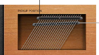
Chapter 16 Vintage Clav 437
Use Vintage Clav Pickup parameters
The original D6 is equipped with two electromagnetic pickups, much like those found in electric
guitars—one below the strings (lower) and one above the strings (upper). In contrast to the
xed pickups of the original instrument, Vintage Clav pickups can be set to arbitrary positions
and angles.
Upper pickup
Lower pickup
Try moving pickup positions while repeatedly striking a note to hear the eect that the pickup
position has on the overall tone. Interesting, phaser-like eects can be achieved by automating
the pickup positions.
Settings with both pickups placed near the upper end of the strings and active Brilliant and
Treble lter switches result in a weak fundamental tone. Therefore, you will mostly hear the
overtones of the chosen model. These can be “out of tune,” particularly for models such as
Wood, which has strong inharmonic content. Move the pickups toward the center of the Pickup
Position display, halfway along the strings, and deactivate all lter switches to circumvent this
detuned eect.
You can cross-over the pickups in the Pickup Position display. This may lead to a “hole” (silent or
very quiet notes) in your keyboard range. This is due to phase cancelations between the pickups.
If you encounter this phenomenon, adjust the position of one or both pickups—until the quiet
or silent notes are playable.
Adjust a pickup angle
mDrag the “dot” at one end of a pickup to another position.
Reposition a pickup
mDrag the “dot” in the middle of the pickup to a new position along the strings.
Change the Vintage Clav pickup mode
mClick the AB and CD switches to change pickup modes.
The internal wiring of the two pickups changes with dierent switch positions, as does the sound
at the combined pickup output.
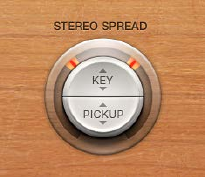
Chapter 16 Vintage Clav 438
Use Vintage Clav Stereo Spread parameters
Unlike the original D6, Vintage Clav has a stereo output that you congure with the Stereo
Spread parameter. It is divided into two halves: Key and Pickup.
The Key parameter sets a key scale modulation of the panning position. In other words, the
played keyboard note position determines the panning position.
The Pickup parameter allows you to spread the two pickup signals across the stereo spectrum—
when both pickups are active (Upper+Lower and Upper-Lower pickup modes).
You can use both spread types at the same time. They are automatically mixed. The ring around
the Stereo Spread button graphically displays the eect of both parameters, as follows:
•The key scale range is indicated by orange areas in the ring.
•The pickup panning position is indicated by red lines in the ring.
Adjust the keyboard position
mVertically drag in the upper (Key) half of the circular Stereo Spread button. The center position is
MIDI note number 60 (C3).
Set this parameter to the maximum value for extreme left/right panning (semitones) at MIDI
note number 60.
Adjust the pickup position in the stereo eld
mVertically drag in the lower (Pickup) half of the circular button. Higher Pickup values move the
signals of both pickups away from the center position—one to the right, and the other to the
left.
Set this parameter to the maximum value for extreme left/right panning.

Chapter 16 Vintage Clav 439
Vintage Clav Eects window
Vintage Clav Eects window overview
No clavinet simulation would be complete without a selection of eect processors. Vintage Clav
incorporates three “classic” foot-pedal eect emulations: Distortion, Modulation, and Wah. Each
eect is modeled on pedals that were available in the heyday of the Clavinet—the 1970s—
adding an authentic sound to your performances. A simple compression circuit is also included
and can be placed anywhere in the eects chain.
Click the Master button to turn the entire eects section on or o. Each eect in the eects chain
can be independently turned on or o.
Vintage Clav eects work in series—where the output of one eect is fed into the next in an
eects chain. The routing order lets you choose whether a distorted signal should be wah-
ltered (for funkier sounds) or the wah-ltered sound should be distorted (for screaming
sounds)—as an example.
Horizontally drag the name of the eect to determine the order of the eects chain.
Drag a panel to determine the
order of the effect chain.

Chapter 16 Vintage Clav 440
Vintage Clav Compressor eect
The Compressor eect is normally used just before the Distortion eect. This allows you to
increase or decrease the perceived gain, thus providing a suitable input level to the Distortion
circuit. You can, however, place the Compressor at any position in the eects chain or can disable
it completely.
Compressor eect parameters
•On/o button: Turns the Compressor eect on or o.
•Ratio knob: Rotate to adjust the compression slope. The additional gain oered by the
compression circuit—when directly preceding the Distortion eect—lets you create
crunchy distortions. The Compressor is also useful for enhancing the key click sound and for
emphasizing harmonics in dierent clavinet models.
Vintage Clav Distortion eect
The Distortion eect can provide warm overdrive or aggressive distortion.
Distortion eect parameters
•On/o button: Turns the Distortion eect on or o.
•Gain knob: Rotate to set the level of the Distortion eect. If Gain is at the minimum value, no
distortion is heard.
•Tone knob: Rotate to change the tonal color of the Distortion eect.
•Use low Tone and Gain settings to create warm overdrive eects.
•Use high Tone and Gain settings for bright, screaming distortion eects.

Chapter 16 Vintage Clav 441
Vintage Clav Modulation eect
Vintage Clav features a choice of three modulation eect types: Phaser, Flanger, or Chorus.
Modulation eect parameters
•On/o button: Turns the Modulation eect on or o.
•Mode pop-up menu: Choose Phaser, Flanger, or Chorus as the modulation eect.
•Intensity knob: Rotate to set the depth of the phasing, anging, or chorus eect. Use of high
Intensity values leads to ensemble-type eects when the Chorus eect is active.
WARNING: When the Phaser eect is active, high Rate and Intensity values lead to very deep,
self-oscillating phase shifts that can damage ears and speakers.
•Sync button: Turn on to synchronize the Phaser or Flanger eect to the host application tempo.
The Rate knob sets bar and beat values, including triplets.
•Rate knob: Rotate to set the speed of the phasing, anging, or chorus eect. The rate is set in
hertz values, or bar/beat values when the Sync button is turned on.

Chapter 16 Vintage Clav 442
Vintage Clav Wah eect
Vintage Clav provides simulations of several classic wah eects, as well as some basic lter
types. The name wah comes from the sound it produces. It has been a popular eect (usually a
pedal eect) with electric guitarists since the days of Jimi Hendrix. The pedal controls the cuto
frequency of a bandpass, lowpass, or—less commonly—highpass lter. Wah wah pedals are also
used extensively with the D6. For information about assigning a controller to the Wah eect, see
Vintage Clav Misc parameters.
Wah eect parameters
•On/o button: Turns the Wah eect on or o.
•Mode pop-up menu: Choose a Wah eect type.
•Classic Wah: This setting mimics the sound of a popular wah pedal with a slight
peak characteristic.
•Retro Wah: This setting mimics the sound of a popular vintage wah pedal.
•Modern Wah: This setting mimics the sound of a distortion wah pedal with a constant
Q(uality) Factor setting. The Q determines the resonant characteristics. Low Q values aect
a wider frequency range, resulting in softer resonances. High Q values aect a narrower
frequency range, resulting in more pronounced emphasis.
•Opto Wah 1: This setting mimics the sound of a distortion wah pedal with a constant
Q(uality) Factor setting.
•Opto Wah 2: This setting mimics the sound of a distortion wah pedal with a constant
Q(uality) Factor setting.
•Resonant LP: In this mode, the Wah works as a resonance-capable lowpass lter. At the
minimum pedal position, only low frequencies can pass.
•Resonant HP: In this mode, the Wah works as a resonance-capable highpass lter. At the
maximum pedal position, only high frequencies can pass.
•Peak: In this mode, the Wah works as a peak (bell) lter. Frequencies close to the cuto
frequency are emphasized.
•Range knob: Rotate to set the cuto frequency of the lter. At the extreme left position, Range
limits cuto modulation to a narrow frequency range. To provide a wider control range, turn
the Range knob to the right.
•Envelope knob: Rotate to determine the sensitivity of the (lter) envelope to incoming note
velocity messages. An auto wah eect is produced by using the integrated envelope follower
function, which controls the depth of lter cuto modulation. In practical terms, this means
that the dynamics of your performance directly control the depth of the Wah eect.
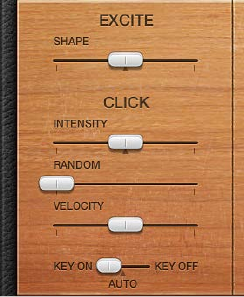
Chapter 16 Vintage Clav 443
Vintage Clav Details window
Vintage Clav Details window overview
The Details window lets you precisely control the modeling parameters of Vintage Clav and also
provides global parameters that aect the overall instrument. See these sections for details:
•Vintage Clav Excite and Click parameters
•Vintage Clav String parameters
•Vintage Clav Pitch parameters
•Vintage Clav Misc parameters
Vintage Clav Excite and Click parameters
The Excite parameter describes the string excitation, emulating the characteristics and power of
the hammers striking the string, and other elements that form part of the initial key strike.
The rubber hammers of the original D6 age and decay, just like piano hammer felts. Worn out D6
units produce a distinctive “click” when a key is released. This is due to the string sticking to the
rubber hammer before being released. The characteristics of this release click are part of each
model and can be precisely adjusted with the Click parameters.
Excite and Click parameters
•Shape slider: Drag to contour the attack shape, simulating the hardness of the rubber hammers
in a D6. As the instrument ages, hammers wear and split, changing brightness and tone.
Negative values—to the left—provide a softer attack, and positive values result in a harder
attack.
•Intensity slider: Drag to set the level of the release click. A negative value of −1.00 eliminates
the release click. To simulate an old D6, increase the value.
•Random slider: Drag to control the amount of click level variance across the keyboard. This
slider simulates the wearing of some hammers, but not others, emulating the real-world
“wear and tear” of a D6. The farther to the right the slider is moved, the greater the variation
between key clicks on some keys. At the leftmost position, all keys have an identical key click
level.
•Velocity slider: Drag to set the velocity sensitivity for the key click sound. The maximum key
click level is set with the Intensity slider and the velocity mode is determined with the Velocity
mode switch.
•Velocity mode switch: Turns attack (key on) or release (key o) velocity on or o. The Auto
setting senses if the connected MIDI keyboard is sending release velocity values. If this is
the case, the received release velocity is used to shape the sound; otherwise, it acts as if it is
turned o.

Chapter 16 Vintage Clav 444
Vintage Clav String parameters
The selected model determines the basic qualities of the strings and has a signicant bearing on
the behavior, and impact, of each String parameter. This is primarily due to the dierent harmonic
content present in each model.
String parameters
•Release slider: Drag to set the release time of the strings, following the decay phase of a played
note. Positive Release values provide a longer release time—after you have released a key.
•Damping slider: Drag to change the damping behavior of the strings. Damping is essentially
a faster decay for the higher harmonics in a sound. Damping is directly related to the string
material properties—high damping for catgut strings, medium damping for nylon strings, and
low damping for steel strings. Depending on the model, damping results in a more mellow
and rounded, or woody, sound. A positive Damping value makes the sound more mellow. A
negative Damping value allows more high harmonics through, making the sound brighter.
•Stiness and Inharmonicity sliders: Drag to intensify or reduce the inharmonic overtones in the
sound. When set at dierent levels, you can create metallic, bell-like sounds, or DX-style electric
piano sounds. Stiness and Inharmonicity can also be useful for wood bass sounds.
•The Inharmonicity parameter determines the lowest harmonic—the harmonic
threshold. Inharmonic content above this threshold is stretched or spread across the
frequency spectrum.
•The Stiness parameter controls the intensity of the stretching or spectral spreading set by
the Inharmonicity slider.
Note: The fundamental note pitch is not aected by the Stiness and
Inharmonicity parameters.
•Tension Mod slider: Drag to add a slight upward pitch bend eect, immediately after being
plucked, struck, or strummed. This type of modulation is common to stringed instruments like
the D6, guitars, and so on. A predened Tension Modulation characteristic is built into each
model, but this can be altered with the Tension Mod parameter. The impact of this parameter
can be signicant, enabling you to generate strange sound eects with Vintage Clav. You can
also use it to simulate an out-of-tune clavinet, or a sitar-like sound.
•Pitch Fall slider: Drag to set the intensity of a D6 characteristic, where the pitch of each note
falls immediately after you release the key. This sonic quirk is due to the physical construction
of the D6. The intensity of this eect varies with each model, but it can be completely
deactivated by setting Pitch Fall to the leftmost position.
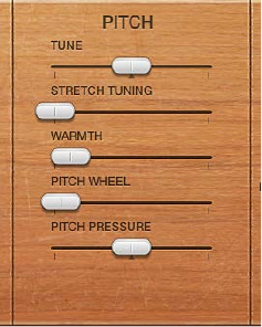
Chapter 16 Vintage Clav 445
Vintage Clav Pitch parameters
The Pitch parameters aect the tuning of the selected model.
Pitch parameters
•Tune slider: Drag to adjust tuning in one-cent intervals. A value of 0 equals concert pitch A
440 Hz.
•Stretch Tuning slider: Vintage Clav is tuned to an equal-tempered scale. You can deviate from
this standard tuning by using Stretch to alter the tuning in the bass and treble ends of the
sound. This simulates the way stringed keyboard instruments such as pianos are tuned (see
information below).
Note: Use of both Warmth and Stretch may result in a detuned sound that is quite similar to a
heavy chorus eect. In some instances, this eect may be so extreme that Vintage Clav sounds
out of tune with your project or concert.
•Warmth slider: Drag to set the amount of random deviation from an equal-tempered scale.
High values add life to sounds. The Warmth parameter can be useful when you are emulating
an instrument that has not been tuned for a while, or for slightly thickening a sound. When
you are playing chords, the Warmth parameter creates a slight detuning or beating eect
between notes.
•Pitch Wheel slider: Drag to determine the pitch bend range in semitone steps. You can use your
keyboard’s pitch bend wheel/stick to control pitch bends.
•Pitch Pressure slider: On an original D6, applying pressure (aftertouch) to a depressed key raises
the pitch slightly. Pitch pressure emulates this behavior. Pitch Pressure parameter values to the
left of the center position lower the pitch slightly with aftertouch messages. Values to the right
raise pitch.

Chapter 16 Vintage Clav 446
Stretch tuning in acoustic instruments
The tones of upright pianos, and to a lesser extent grand pianos (due to their longer strings),
have inharmonicities in their harmonic structure. This also applies to other stringed instruments,
but it particularly aects pianos due to the length, density, and tension of the strings. If a piano
is perfectly tuned to equal temperament across the keyboard range, the overtones of the low
strings and the fundamentals of the high strings will sound out of tune with each other.
To circumvent this problem, piano tuners use a technique known as stretch tuning, where the
high and low registers of the piano are tuned higher and lower, respectively. This results in the
harmonics of the low strings being in tune with the fundamental tones of the upper strings. In
essence, pianos are intentionally “out of tune” (from equal temperament), so that the lower and
upper registers will sound in tune.
Because the original D6 is a stringed instrument, this inharmonic relationship also applies
to Vintage Clav and the instruments it emulates. The stretch feature, however, was primarily
included for situations where you want to use Vintage Clav alongside an acoustic piano
recording or performance.
Vintage Clav Misc parameters
The Misc(ellaneous) parameters aect the entire Vintage Clav instrument, rather than an
individual model.
MIDI controller assignments allow you to control Vintage Clav with an external MIDI controller or
with your host application.
Misc parameters
•Voices pop-up menu: Choose the maximum number of voices that can be played
simultaneously. Lowering the value of this parameter limits the polyphony and processing
requirements of Vintage Clav. There are two monophonic settings: mono and legato. Each
setting provides a single voice when playing Vintage Clav.
•Mono: Vintage Clav voice is triggered each time a key is pressed.
•Legato: Vintage Clav sound-shaping processes are not triggered if the notes are played
legato—only the pitch changes. If the notes are played staccato, a Vintage Clav voice with all
sound-shaping processes is triggered.
Chapter 16 Vintage Clav 447
•Velocity Curve pop-up menu: Choose one of nine preset velocity curves to suit your playing
style or the selected model. The nine curves available are: fx25%, fx50%, fx75%, fx100%,
convx1, convx2, linear (the default), concv1, and concv2.
•Fixed (fx) curves: These are linear curves with a xed dynamic range of 25%, 50%, 75%, and
100%.
•Convex (convx) curves: These curves are more dynamically responsive in the center octaves of
the keyboard range.
•Concave (concv) curves: These curves are less dynamically responsive in the center octaves of
the keyboard range.
•Damper Control pop-up menu: Choose the MIDI controller (or MIDI velocity or aftertouch) you
want to use to control the Damper parameter. O disables MIDI control.
•Wah Control pop-up menu: Choose the MIDI controller you want to use as a manual Wah eect
control. MIDI foot controllers such as Expression pedals are commonly used for this type
of task, but any controller can be assigned. You can also use MIDI velocity or aftertouch
messages to control the Wah eect. O disables MIDI control. Choose the Learn menu item to
automatically assign the parameter to the rst appropriate incoming MIDI data message, then
move the controller on your MIDI keyboard. Learn mode has a 20 second time-out feature: If
Vintage Clav does not receive a MIDI message within 20 seconds, the parameter reverts to its
original MIDI controller assignment.
Note: You can simultaneously control the Wah eect with both the integrated envelope
follower function (“auto-wah”—see Vintage Clav Wah eect on page 442) and a manual
controller. In this situation, the controller events of the envelope follower and manual controls
are mixed.
•Wah Pedal Position slider (Controls view): Choose View > Controls to access the Wah Pedal
Position slider. The value of this parameter represents the current pedal position, ensuring
that it is saved with the setting. Choose the Learn menu item to automatically assign the
parameter to the rst appropriate incoming MIDI data message, then move the controller
on your MIDI keyboard. Learn mode has a 20 second time-out feature: If Vintage Clav does
not receive a MIDI message within 20 seconds, the parameter reverts to its original MIDI
controller assignment.
Vintage Clav extended parameters
Vintage Clav provides two parameters that can be accessed by clicking the disclosure triangle at
the lower left of the interface.
Extended parameters
•MIDI Mono Mode pop-up menu: Choose O, On (with common base channel 1), or On (with
common base channel 16).
In either Mono mode, each voice receives on a dierent MIDI channel. Controllers and MIDI
messages sent on the base channel aect all voices.
•Mono Mode Pitch Range pop-up menu: Choose 0, 24, or 48.
The chosen pitch bend range aects individual note pitch bend messages received on
all but the common base channel. The default is 48 semitones, which is compatible with
Mobile GarageBand’s keyboard in pitch mode. When using a MIDI guitar, 24 semitones is the
preferable setting because most guitar to MIDI converters use this range by default.
Chapter 16 Vintage Clav 448
D6 Clavinet information
D6 Clavinet history
The German company Hohner, manufacturer of the D6 Clavinet, was known mainly for its
reed instruments (harmonicas, accordions, melodicas, and so on) but had made several classic
keyboards prior to the rst incarnation of the Clavinet, known as the Cembalet.
Musician and inventor Ernst Zacharias designed the Cembalet in the 1950s. It was intended to
be a portable version of the cembalo, or harpsichord—which could be amplied. Its mechanism
worked by plucking the end of a at reed with the key, which was then picked up and amplied,
in much the same way as an electric guitar.
A year or two after the Cembalet’s release, two Pianet models appeared. Both the CH and N
models used at reeds for tone generation but employed a very dierent plucking/striking
action. When a key was depressed, it engaged a sticky pad with a foam backing, which actually
stuck to the reed. When the key was released, the weight of the key caused the pad adhesive to
free itself from the reed. This made the reed vibrate, and this vibration was then amplied.
The model T Pianet was released several years later and utilized a soft rubber suction pad on the
reeds, rather than the adhesive of the CH and N models. This method still had several drawbacks,
however, because the dynamics available from the keyboard were limited. As a further
shortcoming, all reeds were damped on release, thus negating any possibility of sustaining the
sound via a foot pedal. Despite these problems, the sound of the model T Pianet was popularized
by bands such as the Zombies and Small Faces in the 1960s.
In the years between the releases of the Pianet N and T models, Zacharias invented what was to
become Hohner’s most successful, and certainly funkiest, keyboard—the Clavinet. The Clavinet
was designed to replicate the sound of a clavichord, but with an altogether fuller sound (the
clavichord was notoriously thin sounding).
The early models—Clavinet I with a built-in amp, Clavinet II with tonal lters, Clavinet L with its
bizarre triangular shape—all led to the Clavinet model C. This, in turn, was rened into the more
portable D6. The D6 uses a hammer action, which strikes a string against a metal surface to
produce a tone. It has a fully dynamic keyboard because the striker is directly beneath the key—
the harder you hit, the louder and more vibrant the tone.
Mention the Clavinet today and most people will automatically think of Stevie Wonder’s
“Superstition”—a recording that owes as much to the D6 as it does to the artist who wrote
and performed it. The D6 was later superseded by the E7 and the Clavinet/Pianet Duo. These
were basically the same as the D6 but more roadworthy, quieter, and better protected against
proximity hums than previous models.
Chapter 16 Vintage Clav 449
D6 Clavinet mechanical details
Each D6 keyboard key forms a single arm lever. When a key is depressed, a plunger below
the key strikes the string and presses it onto an anvil. The string hits the anvil with a strength
determined by key velocity, thus aecting both the dynamics and harmonics of the sounding
string.
The mechanical vibrations of the action are captured by magnetic pickups and converted into
electrical signals, which are amplied and reproduced through speakers.
As the key is released, contact between the plunger/striker and the anvil is immediately broken,
leaving the wool-wound part of the string free. This immediately suppresses the string vibration.
When experimenting with Vintage Clav, or auditioning some of the included settings, you may
encounter sounds that seem to be triggered on both the note on and the note o.
This is actually a feature that emulates the original D6. The real D6 has the “problem” of strings
sticking to worn-out hammers, producing a second trigger when the key is released. You can
adjust the intensity of this key-o click using the Intensity slider. See Vintage Clav Excite and Click
parameters on page 443.
450
Vintage Electric Piano overview
Vintage Electric Piano simulates the sound of various Rhodes and Wurlitzer pianos as well
as the sound of the Hohner Electra Piano. See Rhodes models on page 459 and Hohner and
Wurlitzer models.
The unmistakable tones of Fender Rhodes pianos are some of the best-known keyboard
instrument sounds used in the second half of the 20th century. Various Rhodes models have
been popularized in a wide range of musical styles, encompassing pop, rock, jazz, and soul, as
well as more recent genres such as house and hip-hop. Nearly as popular was the Wurlitzer
piano, which enjoyed most of its success in the 1970s.
Vintage Electric Piano’s sound engine uses component modeling techniques to generate
ultrarealistic electric piano sounds, with smooth dynamics and scaling over the entire 88-key
range. Component modeling has no abrupt changes between samples, sample looping, or
ltering eects during the decay phase of notes.
Vintage Electric Piano also simulates the physical characteristics of the original instruments,
including the movement of the electric piano reeds, tines, and tone bars in the (electric and
magnetic) elds of the pickups. It also emulates the ringing, smacking, and bell-like transients of
the attack phase as well as the hammer action and damper noises of the original instruments.
See Component modeling synthesis on page 494.
The integrated eects include classic equalizer, overdrive, stereo phaser, stereo tremolo, and
stereo chorus eects that are commonly used with electric piano sounds.
Vintage Electric Piano 17

Chapter 17 Vintage Electric Piano 451
Vintage Electric Piano interface
Vintage Electric Piano is divided into four areas. The control bar at the top lets you choose an
electric piano model and provides access to further controls shown in the main display. The
central area gives you direct access to Bass Boost and Volume controls. Extended parameters are
available at the bottom of the interface.
Click the control bar Eects and Details buttons to update the main display.
Model pop-up menu
Click to update the
main display.
Main display
Click to open extended
parameters.
•Model pop-up menu: Choose an electric piano model. Several Rhodes models are available, plus
Hohner Electra Piano and Wurlitzer models. See Rhodes models on page 459 and Hohner and
Wurlitzer models.
Note: When you choose a new model, all currently sounding voices are muted and all
parameters are reset to default values.
•Eects button: Click to show the EQ, Drive, Phaser, Tremolo, and Chorus eect parameters in the
main display area.
•Details button: Click to show parameters in the main display area that enable you to alter the
tone and playing behavior of the selected instrument model.
•Bass Boost knob: Rotate to enhance the low end of the sound. This parameter emulates the
behavior of the control found on the original Rhodes piano.
•Volume knob: Rotate to set the overall output level of Vintage Electric Piano.
•Extended parameters: Click the disclosure triangle at the lower left to access Vintage Electric
Piano extended parameters if needed.
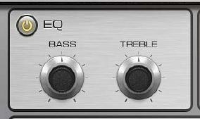
Chapter 17 Vintage Electric Piano 452
Vintage Electric Piano Eects window
Vintage Electric Piano EQ
The EQ allows you to boost or cut the high and low frequency ranges of your Vintage
Electric Piano sound. The EQ is positioned after the Drive circuit in the Vintage Electric Piano
eects chain.
EQ parameters
•On/o button: Turns the equalizer on or o.
•Bass knob: Rotate to control the low frequency range. Either shelving or peak-type lters are
used—depending on the piano model selected. Optimized frequency ranges are preselected
for each model.
•Treble knob: Rotate to control the high frequency range. Either shelving or peak-type lters are
used—depending on the piano model selected. Optimized frequency ranges are preselected
for each model.
Tip: You can achieve a sound with a more dominant mid-range by suppressing the treble
and bass frequency ranges. If you require more precise equalization, you can insert any of the
equalizer plug-ins in the instrument channel strip. You can also use the Tone control of the
Drive eect to contour the harshness of your sound.

Chapter 17 Vintage Electric Piano 453
Vintage Electric Piano Drive eect
Electric pianos sound best when played through tube ampliers. Tube ampliers oer a wide
range of tones—from the subtle warmth or crunch of guitar ampliers to psychedelic, screaming
rock distortions. The Vintage Electric Piano Drive eect simulates the saturation characteristics of
a tube amplier stage. The Drive eect is the rst signal processing circuit in the Vintage Electric
Piano eects chain.
Drive eect parameters
•On/o button: Turns the Drive eect on or o.
•Distortion Type switch: Switch between two types of distortion eect.
•Gain knob: Rotate to set the amount of harmonic distortion.
•Tone knob: Rotate to equalize the sound before it is amplied or distorted by the virtual tube
amplier circuit.
•Use low Tone values to set a mellow tonal color. If the sound becomes too soft, boost the
treble portion of your sound with the EQ Treble control.
•Use higher Tone values for harsh distortion characteristics, typical of overdriven transistor
stages. If the sound is too aggressive, suppress the treble portion of your sound with the EQ
Treble control.
Vintage Electric Piano Chorus eect
Chorus is the most commonly used eect on electric piano sounds. The Vintage Electric Piano
Chorus eect is based on a delay circuit. The delay time is modulated by an LFO. The delayed
eect signal is mixed with the original signal.
Chorus parameters
•On/o button: Turns the Chorus eect on or o.
•Rate knob: Rotate to set the speed of the Chorus eect, in Hz. High values may result in the
piano sounding detuned.
•Intensity knob: Rotate to set the intensity of the Chorus eect (technically, the amount of delay
time deviation).
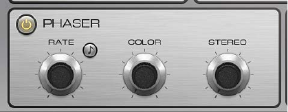
Chapter 17 Vintage Electric Piano 454
Vintage Electric Piano Phaser eect
The Vintage Electric Piano Phaser eect is based on analog phaser pedals used by electric
guitarists in the 1960s and 1970s, including the subtle analog-style distortion typical of these
units. These phaser pedals were also popular among electric pianists—especially in the electric
jazz, jazz-rock, and pop styles of the 1970s.
The Phaser eect runs the original signal through a series of four lters that enhance particular
aspects of the Vintage Electric Piano frequency spectrum. This ltered signal is slightly phase
delayed and mixed with the original signal, resulting in notches in the frequency spectrum. The
notches in the phase-delayed signal are moved up and down through the frequency spectrum
by an LFO (low frequency oscillator) modulation. This results in the amplitudes of the two signals
reaching their highest and lowest points at slightly dierent times.
Note: MainStage oers a sophisticated Phaser eect (and other modulation plug-ins) that can be
used alongside, or to replace, the integrated Vintage Electric Piano Phaser eect.
Phaser eect parameters
•On/o button: Turns the Phaser eect on or o.
•Rate knob: Rotate to set the speed of the phasing eect. The rate is set in Hz values, or bar/beat
values when the Sync button is turned on.
•Sync button: Turn on to synchronize the Phaser eect to the host application tempo. The Rate
knob sets bar and beat values, including triplets.
•Color knob: Rotate to set the amount of Phaser output signal that is fed back into the Phaser
eect input. This changes the tonal color of the phasing eect.
•Stereo knob: Rotate to determine the relative phase shift between the left and right channels.
•At a value of 0 the eect is most intense, but not stereophonic.
•At a value of 180 the eect symmetrically rises in the left channel while falling in the right
channel, and vice versa.
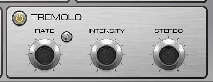
Chapter 17 Vintage Electric Piano 455
Vintage Electric Piano Tremolo eect
A periodic modulation of the amplitude (level) of the sound is known as a tremolo. This
modulation is controlled with an LFO in Vintage Electric Piano. The Fender Rhodes suitcase piano
features a stereo tremolo. Other electric pianos have a simple, often obtrusive, mono tremolo
that can introduce an unusual polyrhythmic feel to performances.
Tremolo eect parameters
•On/o button: Turns the Tremolo eect on or o.
•Rate knob: Rotate to set the speed of the tremolo eect (LFO frequency). The rate is set in Hz
values, or bar/beat values when the Sync button is turned on.
•Sync button: Turn on to synchronize the Tremolo eect to the host application tempo. The Rate
knob sets bar and beat values, including triplets.
•Intensity knob: Rotate to set the amount of amplitude modulation.
•Stereo knob: Rotate to determine the relative phase shift between the left and right channels.
•A value of 0 changes the level of both channels—in phase.
•A value of 180 (out-of-phase modulation), results in a stereo tremolo eect that is also
known as auto panning. This is similar to manually turning the pan pot from side to side.
Tip: The original Wurlitzer Piano has a mono tremolo with a xed modulation rate of 5.5 Hz.
For an authentic Wurlitzer sound, select a Stereo value of 0 degrees. For Rhodes sounds, set
the Stereo value to 180 degrees. The settings in between result in spacious eects—especially
when low Rate knob values are used.

Chapter 17 Vintage Electric Piano 456
Vintage Electric Piano Details window
Vintage Electric Piano model parameters
Click the Details button on the control bar to use the model parameters. The model parameters
aect the currently selected model.
Model parameters
•Voices knob: Rotate to set the maximum number of voices that can sound simultaneously.
Lower the value to limit polyphony. When Voices is set to 1, Vintage Electric Piano is
monophonic. The maximum value is 88, allowing for glissandi over the entire keyboard range
when the sustain pedal is depressed.
•Decay knob: Rotate to set the decay time of the piano sound. The lower the value, the less the
sound sustains and the higher the level of damping applied to the vibration of the tines. When
short values are set, the main tone is more pronounced and is heard for a longer period than
the transient harmonics. Sonically, the eect is reminiscent of an electric guitar string being
damped with the palm of the picking hand. Electric pianos can be modied in a similar way.
Higher values (longer settings) result in more sustain and a less dynamic feel.
•Release knob: Rotate to set the amount of damping applied after the keys are released.
Extremely long settings (high Release values) let you play the piano like a vibraphone.
•Stereo Width knob: Rotate to set the sound’s stereo eld. At high values, bass notes are heard in
the left channel and treble notes are heard in the right channel.
Tip: Avoid using this parameter if you are trying to faithfully recreate a vintage electric piano
because these instruments were not equipped with stereo outputs.
•Tine Bell knob: Rotate to set the level of the (inharmonic) treble portion of the tone. This is
useful for emulating classic electric piano sounds.
•Damper Noise knob: Rotate to set the level of damper noise caused by the damping felt hitting
the vibrating tine of the original instruments.

Chapter 17 Vintage Electric Piano 457
Vintage Electric Piano pitch parameters
Click the Details button on the control bar to use the pitch parameters. Vintage Electric Piano is
tuned to an equal-tempered scale. You can deviate from this scale and can stretch the tuning in
the bass and treble ranges, much as you can do with acoustic pianos (especially upright pianos).
You can also modulate the tuning of each note randomly.
Pitch parameters
•Tune knob: Rotate to tune Vintage Electric Piano in one-cent increments. A value of 0 equals
concert pitch A (440 Hz). The range is plus or minus half a semitone.
•Down/Up (Bend Range) knobs: Rotate to set the pitch bend range in semitone steps.
•Warmth knob: Rotate to set the amount of (random) deviation from the equal-tempered scale.
Each note is slightly detuned from the next, adding life and richness to the sound, particularly
when high Warmth values are used.
Note: Use of both Warmth and Upper or Lower Stretch can result in a detuned sound that is
similar to a heavy chorus eect. In some instances, this eect may be so extreme that Vintage
Electric Piano sounds out of tune with the rest of your project or concert.
•Lower (Stretch Tuning) knob: Rotate to set the amount of deviation from the equal-tempered
scale in the bass end of the sound. The higher the value, the farther down the low notes are
tuned. At a setting of 0, Vintage Electric Piano is tuned to an equal-tempered scale, with each
octave down halving the frequency.
•Upper (Stretch Tuning) knob: Rotate to set the amount of deviation from the equal-tempered
scale in the treble end of the sound. The higher the value, the farther up the high notes are
tuned. At a setting of 0, Vintage Electric Piano is tuned to an equal-tempered scale, with each
octave above (up) doubling the frequency.

Chapter 17 Vintage Electric Piano 458
Stretch tuning in acoustic instruments
The tones of upright pianos, and to a lesser extent grand pianos (due to their longer strings),
have inharmonicities in their harmonic structure. This also applies to other stringed instruments,
but it particularly aects pianos due to the length, density, and tension of the strings. If a piano
is perfectly tuned to equal temperament across the keyboard range, the overtones of the low
strings and the fundamentals of the high strings will sound out of tune with each other.
To circumvent this problem, piano tuners use a technique known as stretch tuning, in which the
high and low registers of the piano are tuned higher and lower, respectively. This results in the
harmonics of the low strings being in tune with the fundamental tones of the upper strings. In
essence, pianos are intentionally “out of tune” (from equal temperament), so that the lower and
upper registers will sound in tune.
Electric pianos don’t have strings, so this inharmonic relationship doesn’t apply to Vintage
Electric Piano nor to the original instruments it emulates. The stretch feature was primarily
included for situations where you want to use Vintage Electric Piano alongside an acoustic piano
recording or performance.
Vintage Electric Piano extended parameters
Click the disclosure triangle at the lower left of Vintage Electric Piano to show or hide the
extended parameters.
Extended parameters
•Delay PP slider and eld: Drag to set the delay time (in milliseconds) when the keys are struck
pianissimo (PP-soft).
•Delay FF slider and eld: Drag to set the delay time (in milliseconds) when the keys are struck
forte (FF-hard).
•Midi Mode pop-up menu: Determine how Vintage Electric Piano responds to MIDI controllers.
Choose from: O, Modwheel to Tremolo, and Full Remote.
Chapter 17 Vintage Electric Piano 459
Vintage Electric Piano emulations
Rhodes models
Harold Rhodes (born 1910) constructed what is arguably the best known and most widely
used electric piano. Designed in 1946—as a piano surrogate for practice, education, and army
entertainment—the Rhodes piano was marketed by guitar manufacturer Fender from 1956. The
Fender Rhodes is one of the most popular musical instruments in jazz, especially electric jazz.
CBS took over production of the Rhodes in 1965, enhancing its popularity in pop and rock music.
There are also a number of Rhodes synthesizers, developed by former manufacturer ARP. Japan’s
Roland corporation owned the Rhodes name for a while and released several digital pianos
under the Rhodes moniker. From 1997 until his death in December 2000, Harold Rhodes again
owned the name.
The Rhodes piano was also made available as a suitcase piano (with pre-amplier and two-
channel combo amplier) and as a stage piano, without amplier. Both of these 73-key “portable”
versions have a vinyl-covered wooden frame and a rounded plastic top. In 1973, an 88-key model
was introduced. Smaller Celeste and bass versions were less popular. The MkII (1978) had a at
top that allowed keyboardists to place extra keyboards on top. The Mark V, introduced in 1984,
had a MIDI output.
The mid-1980s saw a decrease in Rhodes production, as most keyboard players invested in
the lighter, more exible digital synthesizers that became available around this time. These
keyboards could easily emulate the Rhodes sound and also oered a range of new piano sounds.
The Rhodes piano bases its method of sound generation on metal reeds, which function much
like a tuning fork. These reeds are struck with a velocity sensitive hammer action that works in
a similar fashion to that of a grand piano. The asymmetrical tuning fork consists of a thin tine
and a large tone bar that are bolted together. Due to construction considerations, some of the
tone bars are rotated by 90 degrees. The piano is kept in tune by the mass of a spring, which
can be moved along the tine. The tine oscillates in front of an electric pickup, similar to that of
an electric guitar. This oscillation functions along inductive principles, with permanent magnets
placed around the tine that have a damping eect on tine movement and therefore, the sound.
The Rhodes output signal is like that of an electric guitar and requires pre-amplication. The
Rhodes sound is not harmonically rich. This is why so many performers use a treble boost or an
overdrive eect when playing the Rhodes piano. The Rhodes sounds best when played through
tube ampliers.
The characteristic sound of each Rhodes piano depends more on the adjustment and
maintenance of the individual instrument than on the model. Early models had hammers
covered with felt, resulting in a smoother sound than later models with neoprene-covered
hammers. The suitcase piano featured a pre-amplier that could create a sound with a very
dominant mid-range. Appropriate pre-amplication and equalization can, however, deliver an
identical tone from almost any stage piano. The MkII does not have the treble range resonance
clamps of earlier models; it has less sustain in the treble range. The most signicant sonic
dierences are dependent on the proximity of the tine to the pickup. When the tine is moved
closer to the pickup, the bell characteristic becomes more prominent. In the 1980s, many Rhodes
pianos were adjusted to have more “bell.”
Note: The Vintage Electric Piano Metal Piano and Attack Piano models feature “idealized” sound
qualities that could only be aimed at with the original Rhodes instruments. Although these
models may not sound realistic, they have at least partially achieved the ideals that the Rhodes
technicians might have had in mind when preparing their keyboards.
Chapter 17 Vintage Electric Piano 460
Hohner and Wurlitzer models
Not to be confused with the all-electronic RMI Electrapiano, the extremely rare Hohner Electra
Piano oers striking hammers like those of the Rhodes, but a stier keyboard action. It was
designed to resemble the look of a conventional acoustic upright piano. Led Zeppelin’s John Paul
Jones played it on “Stairway to Heaven,” “Misty Mountain Hop,” and “No Quarter.”
Wurlitzer, best-known for manufacturing music boxes and organs, also built electric pianos that
helped write pop and rock music history. The 200 series, notably the 200A and 240V, Wurlitzer
pianos are smaller and lighter than the Rhodes pianos, with a keyboard range of 64 keys (A to C)
and an integrated amplier and speakers.
The velocity sensitive hammer action resembles that of a conventional acoustic piano. The
Wurlitzer sound generation system is based on spring steel reeds that can be tuned with a solder
weight. The Wurlitzer has electrostatic pickups: The reeds are supplied with a 0-volt current and
move between the teeth of a comb, connected to a 150-volt current. The tone of the Wurlitzer,
which was rst manufactured in the early 1960s, features a number of odd harmonics.
The Wurlitzer is best known as the signature piano sound of the band Supertramp, as heard on
their “Crime of the Century” album. You might also recognize the Wurlitzer sound when listening
to Pink Floyd’s “The Dark Side of the Moon” or “I Am the Walrus” by The Beatles.
Note: The Vintage Electric Piano Funk Piano model oers a special synthetic piano engine sound,
with an exaggerated bass. This is not based on any real-world Wurlitzer instruments, but it can be
a very useful sound nonetheless.

Chapter 17 Vintage Electric Piano 461
Vintage Electric Piano MIDI controllers
Vintage Electric Piano responds to the following MIDI continuous controller numbers (CC).
Controller number Parameter name
1 Volume knob
12 Model pop-up menu
13 Model parameters: Decay knob
14 Model parameters: Release knob
15 Model parameters: Tine Bell knob
16 Model parameters: Damper Noise knob
17 Model parameters: Stereo Width knob
18 EQ parameters: Treble knob
19 EQ parameters: Bass knob
20 Drive parameters: Gain knob
21 Drive parameters: Tone knob
22 Phaser parameters: Rate knob
23 Phaser parameters: Color knob
24 Phaser parameters: Stereo knob
25 Tremolo parameters: Rate knob
26 Tremolo parameters: Intensity knob
27 Tremolo parameters: Stereo knob
28 Chorus parameters: Intensity knob
462
Legacy instruments overview
The legacy instruments are less CPU- and memory-intensive versions of equivalent instruments.
All legacy instruments feature a few carefully chosen parameters that provide maximum impact
and exibility, making it easy to create great sounds.
Legacy instruments are automatically loaded when a GarageBand project is imported, or a Logic
project or MainStage concert that uses these instruments is opened.
Display and insert legacy instrument plug-ins
1 Press Option, then click the instrument slot on a channel strip.
The plug-in menu opens, with a Legacy submenu shown below Vintage Electric Piano.
2 Choose the legacy instrument plug-in that you want to insert from the Legacy submenu.
Emulated instruments
Bass
Bass emulates electric and acoustic basses.
•Volume slider: Sets the overall volume level of the instrument.
•Filter Cuto slider: Allows less sound through at low values and more at high values—damping
the sound or making it brighter.
•Release slider: Determines the time it takes for notes to fade out after you let go of the keys on
your keyboard.
Church Organ
Church Organ emulates a pipe organ.
•Volume slider: Sets the overall volume level of the instrument.
•Registration pop-up menu: Provides a number of preset registrations. Registrations are
combinations of dierent pipe organ stop (lever) settings that change the tonal character of
the sound by enabling or disabling specic pipes, thus altering the harmonics that are heard
when you play a key.
•Bass buttons: You can activate the lower (bass) pipes with these buttons, adding these lower
harmonics, which makes your sound richer and fuller.
Note: The bass buttons are not available in all registrations.
•Cuto slider: Allows less sound through at low values and more at high values—damping the
sound or making it brighter.
•Attack slider: Makes the sound start faster or slower. A fast setting makes it sound like striking a
piano key, whereas a slow setting makes it sound like bowing a violin string.
•Release slider: Determines the time it takes for notes to fade out after you let go of the keys on
your keyboard.
Legacy instruments
Appendix
A
Appendix A Legacy instruments 463
Drum Kits
Drum Kits includes: rock, pop, jazz, electronic, orchestral, and Latin kits, among others.
•Volume slider: Sets the overall volume level of the instrument.
•Filter Cuto slider: Allows less sound through at low values and more at high values—damping
the sound or making it brighter.
•Release slider: Determines the time it takes for notes to fade out after you let go of the keys on
your keyboard.
Electric Clav(inet)
Electric Clavinet, which is based on Vintage Clav, emulates the Hohner D6 clavinet.
•Voices pop-up menu: Choose the maximum number of voices that can be played
simultaneously. Lowering the value of this parameter limits the polyphony and processing
requirements of Electric Clav. There are two monophonic settings: mono and legato. Each
setting provides a single voice when playing Electric Clav.
•Mono: Electric Clav voice is triggered each time a key is pressed.
•Legato: Electric Clav sound-shaping processes are not triggered if the notes are played
legato—only the pitch changes. If the notes are played staccato, a voice with all sound-
shaping processes is triggered.
•Damper slider: Changes the tone, making it less sustained and more woody sounding as you
move toward the high setting.
•Volume slider: Sets the overall volume level of the instrument.
•Auto Wah slider: Sets the sensitivity of the (lter) envelope to incoming note velocity messages.
An auto wah eect is produced by using the integrated envelope follower function, which
controls the depth of lter cuto modulation. In practical terms, this means that the dynamics
of your performance directly control the depth of the Wah eect.
•Phaser slider: Sets the overall level of the integrated Phaser eect.
The Phaser eect adds a sweeping, whooshing quality to your clavinet sound.
Electric Piano
Electric Piano, which is based on Vintage Electric Piano, sounds like the Fender Rhodes and
Wurlitzer electric pianos.
•Model buttons: A more bell-like tone is achieved when the Tines button is selected.
•Decay slider: A short value makes the sound almost plucked, whereas a long setting sustains
the sound while the keys are held.
•Bell Volume slider: Makes the sound more bell-like, with a stronger ringing tone.
•Voices pop-up menu: Choose the maximum number of voices that can be
played simultaneously.
•Tremolo slider: Sets the maximum tremolo (wobbling pitch) intensity.
•Chorus slider: Sets the level of the integrated Chorus eect.
Chorus makes the sound richer and thicker.
•Volume slider: Sets the overall volume level of the instrument.
•MIDI Mode pop-up menu: Choose O or Modwheel to Tremolo.
When the latter is chosen, move your keyboard modulation wheel to set the tremolo
(wobbling pitch) intensity.
Appendix A Legacy instruments 464
Guitar
Guitar emulates a number of acoustic and electric guitar sounds.
•Volume slider: Sets the overall volume level of the instrument.
•Filter Cuto slider: Allows less sound through at low values and more at high values—damping
the sound or making it brighter.
•Release slider: Determines the time it takes for notes to fade out after you let go of the keys on
your keyboard.
Horns
Horns emulates several brass sections and a number of individual brass instruments.
•Volume slider: Sets the overall volume level of the instrument.
•Filter Cuto slider: Allows less sound through at low values and more at high values—damping
the sound or making it brighter.
•Attack slider: Makes the sound start faster or slower. A fast setting makes it sound like striking a
piano key, whereas a slow setting makes it sound like bowing a violin string.
•Release slider: Determines the time it takes for notes to fade out after you let go of the keys on
your keyboard.
Piano
Piano emulates a number of classical and jazz piano sounds as well as several accordions and a
harpsichord. It also provides a number of pad sounds.
•Volume slider: Sets the overall volume level of the instrument.
•Filter Cuto slider: Allows less sound through at low values and more at high values—damping
the sound or making it brighter.
•Release slider: Determines the time it takes for notes to fade out after you let go of the keys on
your keyboard.
Sound Eects
Sound Eects provides a number of nature sounds, laughter, applause, and so on.
•Volume slider: Sets the overall volume level of the instrument.
•Filter Cuto slider: Allows less sound through at low values and more at high values—damping
the sound or making it brighter.
•Release slider: Determines the time it takes for notes to fade out after you let go of the keys on
your keyboard.
Strings
Strings emulates string sections and a number of individual stringed instruments. These include
violins, violas, cellos, harps, and several traditional instruments, such as the sitar, koto, and zither.
•Volume slider: Sets the overall volume level of the instrument.
•Filter Cuto slider: Allows less sound through at low values and more at high values—damping
the sound or making it brighter.
•Attack slider: Makes the sound start faster or slower. A fast setting makes it sound like striking a
piano key, whereas a slow setting makes it sound like bowing a violin string.
•Release slider: Determines the time it takes for notes to fade out after you let go of the keys on
your keyboard.
Appendix A Legacy instruments 465
Tuned Percussion
Tuned Percussion emulates a vibraphone, xylophone, timpani, steel drums, and other tuned
percussion instruments.
•Volume slider: Sets the overall volume level of the instrument.
•Filter Cuto slider: Allows less sound through at low values and more at high values—damping
the sound or making it brighter.
•Release slider: Determines the time it takes for notes to fade out after you let go of the keys on
your keyboard.
Voice
Voice emulates a mixed choir.
•Volume slider: Sets the overall volume level of the instrument.
•Filter Cuto slider: Allows less sound through at low values and more at high values—damping
the sound or making it brighter.
•Attack slider: Makes the sound start faster or slower. A fast setting makes it sound like striking a
piano key, whereas a slow setting makes it sound like bowing a violin string.
•Release slider: Determines the time it takes for notes to fade out after you let go of the keys on
your keyboard.
Woodwind
Woodwind emulates the sound of wind instruments, such as utes, clarinets, saxophones, and
several other instruments from various world cultures.
•Volume slider: Sets the overall volume level of the instrument.
•Filter Cuto slider: Allows less sound through at low values and more at high values—damping
the sound or making it brighter.
•Attack slider: Makes the sound start faster or slower. A fast setting makes it sound like striking a
piano key, whereas a slow setting makes it sound like bowing a violin string.
•Release slider: Determines the time it takes for notes to fade out after you let go of the keys on
your keyboard.
Tonewheel Organ
Tonewheel Organ, which is based on Vintage B3, emulates the Hammond B3 organ, but it can
also emulate Farsa, Wurlitzer, and other electric organs.
•Drawbars slider: Drag to increase or decrease the level of sine tones and harmonics, resulting in
a richer or thinner sound.
•Percussion Time slider: Sustains the second or third harmonic when set to a long value. If a short
value is selected, the harmonics are heard only during the initial keystroke.
•Distortion slider: Makes the sound rough, dirty, and noisy.
•Rotary Speaker pop-up menu: Choose one of three speaker eects.
•Slow: Makes the sound swirl.
•Brake: Makes the sound swirl initially and then slow down.
•Fast: Makes the sound wobble.
•Click slider: Introduces a click sound to the keystroke. Select a high level if you’d like this to be
clearly heard.
•Volume slider: Sets the overall volume level of the instrument.
•Percussion Level slider: Sets the level of the second or third harmonic added to the sound with
the Perc. Harmonic buttons.
Appendix A Legacy instruments 466
Synthesizers
Analog Basic
Analog Basic, which is based on the ES2, is a simple analog synthesizer that is useful for a range
of musical styles.
•Volume slider: Sets the overall volume level of the instrument.
•Mix slider: Determines the balance between the oscillator signals.
•Tuning slider: Sets the overall pitch of the instrument.
•Cuto slider: Allows less sound through at low values and more at high values—damping the
sound or making it brighter.
•Resonance slider: Emphasizes the frequency range around the point determined by the
Cuto parameter.
•Attack slider: Makes the sound start faster or slower. A fast setting makes it sound like striking a
piano key, whereas a slow setting makes it sound like bowing a violin string.
•Decay slider: Makes the bright portion of the sound sustain for a longer time at slow values.
Faster values move to the Sustain level more quickly.
•Sustain slider: Determines the level of the sound after the Attack or Decay phase
has completed.
Analog Mono
Analog Mono, which is based on the ES2, is an analog lead synthesizer that is monophonic—only
one note can be played at a time.
•Volume slider: Sets the overall volume level of the instrument.
•Glide slider: Determines the time it takes a note pitch to change, or slide, to another note pitch.
•Mix slider: Determines the balance between the oscillator signals.
•Cuto slider: Allows less sound through at low values and more at high values—damping the
sound or making it brighter.
•Resonance slider: Emphasizes the frequency range around the point determined by the
Cuto parameter.
•Attack slider: Makes the sound start faster or slower. A fast setting makes it sound like striking a
piano key, whereas a slow setting makes it sound like bowing a violin string.
•Decay slider: Makes the bright portion of the sound sustain for a longer time at slow values.
Faster values move to the Sustain level more quickly.
•Richness slider: Determines the complexity of the sound texture, making the sound fuller.
Appendix A Legacy instruments 467
Analog Pad
Analog Pad, which is based on the ES2, can generate warm analog synthesizer pad sounds that
are useful for a range of musical styles.
•Volume slider: Sets the overall volume level of the instrument.
•Modulation slider: Makes the sweeping movement of the pad faster or slower.
•Character slider: Determines whether the sound is soft or sharp.
•Cuto slider: Allows less sound through at low values and more at high values—damping the
sound or making it brighter.
•Resonance slider: Emphasizes the frequency range around the point determined by the
Cuto parameter.
•Cuto Envelope slider: Determines the strength of the sweeping movement.
•Duration slider: Determines the duration of the sweeping movement.
•Animation slider: Determines the envelope’s eect on the pad sound.
Analog Swirl
Analog Swirl, which is based on the ES2, can generate chorused, swirling analog synthesizer
pad sounds.
•Volume slider: Sets the overall volume level of the instrument.
•Modulation slider: Makes the sweeping movement of the pad faster or slower.
•Cuto slider: Allows less sound through at low values and more at high values—damping the
sound or making it brighter.
•Resonance slider: Emphasizes the frequency range around the point determined by the
Cuto parameter.
•Attack slider: Makes the sound start faster or slower. A fast setting makes it sound like striking a
piano key, whereas a slow setting makes it sound like bowing a violin string.
•Decay slider: Makes the harmonic, or bright, portion of the sound sustain for a longer time at
slow values. Faster values move to the Sustain level more quickly.
•Sustain slider: Determines the level of the sound after the Attack or Decay phase
has completed.
•Release slider: Determines the time it takes for notes to fade out after you let go of the keys on
your keyboard.
Appendix A Legacy instruments 468
Analog Sync
Analog Sync, which is based on the ES2, emulates tones from analog synthesizers that
synchronize two oscillators to produce their sound. The Analog Sync instrument is most useful
for hard-edged analog synthesizer lead sounds.
•Volume slider: Sets the overall volume level of the instrument.
•Sync slider: Determines the synchronization (or lack of it) between the two oscillators, and
therefore the harshness of the sound.
•Sync Modulation slider: Determines how much the synchronization of the two oscillators is
modulated, resulting in more complex (and harder) tones.
•Sync Envelope slider: Determines the amount that envelope parameters aect the sound.
•Cuto slider: Allows less sound through at low values and more at high values—damping the
sound or making it brighter.
•Attack slider: Makes the sound start faster or slower. A fast setting makes it sound like striking a
piano key, whereas a slow setting makes it sound like bowing a violin string.
•Decay slider: Makes the harmonic, or bright, portion of the sound sustain for a longer time at
slow values. Faster values move to the Sustain level more quickly.
•Sustain slider: Determines the level of the sound after the Attack or Decay phase
has completed.
Digital Basic
Digital Basic, which is based on the ES2, can generate simple digital synthesizer sounds that are
useful for a range of musical styles.
•Volume slider: Sets the overall volume level of the instrument.
•Mix slider: Mixes two tones together.
•Tuning slider: Sets the overall pitch of the instrument.
•Harmonics slider: Increases or decreases the number of harmonics, or overtones, in the sound.
This can change the sound dramatically or subtly, so feel free to experiment.
•Timbre slider: Changes the color of the sound from dark to bright.
•Attack slider: Makes the sound start faster or slower. A fast setting makes it sound like striking a
piano key, whereas a slow setting makes it sound like bowing a violin string.
•Decay slider: Makes the harmonic, or bright, portion of the sound sustain for a longer time at
slow values. Faster values move to the Sustain level more quickly.
•Release slider: Determines the time it takes for notes to fade out after you let go of the keys on
your keyboard.
Appendix A Legacy instruments 469
Digital Mono
Digital Mono, which is based on the ES2, is ideal for monophonic digital synthesizer lead sounds.
•Volume slider: Sets the overall volume level of the instrument.
•Tuning slider: Sets the overall pitch of the instrument.
•Harmonics slider: Increases or decreases the number of harmonics, or overtones, in the sound,
with more values making the sound a little thicker and less values making it thinner.
•Timbre slider: Changes the color of the sound from dark to bright.
•Timbre Envelope slider: Dynamically changes the color of the sound, depending on how hard
you strike the keyboard.
• Low values result in little or no eect on the color of the sound, no matter how hard you
play the keys.
• High values result in signicant changes in the sound, in response to rmer or softer
keyboard playing.
•Decay slider: Makes the harmonic, or bright, portion of the sound sustain for a longer time at
slow values. Faster values move to the Sustain level more quickly.
•Richness slider: Subtly detunes each played note from the others, making the sound a little
thicker, particularly when high parameter values are used.
•Distortion slider: Distorts the overall sound, making it quite nasty and aggressive.
Important: Be careful with the Distortion parameter, which can signicantly increase the
overall volume of the instrument and possibly cause damage to your speakers or ears.
Digital Stepper
Digital Stepper, which is based on the ES2, is a digital synthesizer that can step through a
number of tones, creating a rhythmic pattern.
•Volume slider: Sets the overall volume level of the instrument.
•Balance slider: Sets the balance between a harder and more spiky sound (digital) and a warmer,
softer sound (analog).
•Modulation slider: Applies more or less modulation, making the sound more lively when high
settings are used.
•Harmonics slider: Increases or decreases the number of harmonics, or overtones, in the sound,
with more values making the sound a little thicker and less values making it thinner.
•Harmonic Steps slider: Determines how noticeable the tonal steps are, with large values making
them more noticeable and small values less noticeable.
•Cuto slider: Allows less sound through at low values and more at high values—damping the
sound or making it brighter.
•Cuto Steps slider: Sets the amount of cuto applied to each step, with large values making the
cuto eect more pronounced and small values less pronounced.
•Duration slider: Sets the length of the steps.
Appendix A Legacy instruments 470
Hybrid Basic
Hybrid Basic is a sample-based synthesizer that can create spectacular sounds.
•Volume slider: Sets the overall volume level of the instrument.
•Waveform pop-up menu: Choose the sample set used to generate the basic synthesizer sound.
•Glide slider: Determines the time it takes a note pitch to change, or slide, to another note pitch.
•Wheel to Vibrato slider: Determines the amount of pitch modulation by your keyboard’s
modulation wheel.
•Wheel to Cuto slider: Determines the depth of Cuto modulation by your keyboard’s
modulation wheel.
•Cuto slider: Allows less sound through at low values and more at high values—damping the
sound or making it brighter.
•Cuto Type pop-up menu: Choose from a number of preset lter curves. Try them out, and
experiment with the Cuto and Resonance parameters.
•Resonance slider: Emphasizes the frequency range around the point determined by the
Cuto parameter.
•Cuto Attack slider: Determines the time it takes before the Cuto parameter begins to aect
the sound.
•Attack slider: Makes the sound start faster or slower. A fast setting makes it sound like striking a
piano key, whereas a slow setting makes it sound like bowing a violin string.
•Decay slider: Makes the harmonic, or bright, portion of the sound sustain for a longer time at
slow values. Faster values move to the Sustain level more quickly.
•Sustain slider: Determines the level of the sound after the Attack or Decay phase
has completed.
•Release slider: Determines the time it takes for notes to fade out after you let go of the keys on
your keyboard.
Appendix A Legacy instruments 471
Hybrid Morph
Hybrid Morph is a sample-based synthesizer that can create spectacular sounds. It diers from
Hybrid Basic in that each waveform is based on two sample layers, which leads to a dierent
sonic character.
•Volume slider: Sets the overall volume level of the instrument.
•Waveform pop-up menu: Choose the sample set used to generate the basic synthesizer sound.
•Morph slider: Controls crossfades between the two sample layers.
•Morph Envelope slider: Controls the morph over time. For example, setting the Morph
parameter to B and the Morph Envelope to “From A to B” morphs the Wave from A to B, in
accordance with the ADSR envelope settings.
Note: If you set the Morph parameter to A and the Morph Envelope to “From A to B,” some
ADSR (envelope) settings will result in no sound. This lets you use the modulation wheel to
oset the Morph parameter during live performances, resulting in interesting sounds.
•Cuto slider: Allows less sound through at low values and more at high values—damping the
sound or making it brighter.
•Cuto Type pop-up menu: Enables you to choose from a number of preset lter curves. Try
them out, and experiment with the Cuto and Resonance parameters.
•Resonance slider: Emphasizes the frequency range around the point determined by the
Cuto parameter.
•Cuto Envelope slider: Determines the strength of the envelope shaping applied to the
Cuto parameter.
•Attack slider: Makes the sound start faster or slower. A fast setting makes it sound like striking a
piano key, whereas a slow setting makes it sound like bowing a violin string.
•Decay slider: Makes the harmonic, or bright, portion of the sound sustain for a longer time at
slow values. Faster values move to the Sustain level more quickly.
•Sustain slider: Determines the level of the sound after the Attack or Decay phase
has completed.
•Release slider: Determines the time it takes for notes to fade out after you let go of the keys on
your keyboard.
472
Synthesizer basics overview
If you are new to synthesizers, this appendix will help you understand the basics of sound itself
and how this applies to synthesizers.
Important facts about synthesizers are discussed and explained, including the dierences
between analog, digital, and virtual analog synthesizers. You will also be introduced to
the major synthesizer terms as you learn about the basic workings of these hardware- or
software-based devices.
This appendix is not a detailed, scientic treatise on the inner workings and mathematical
theories of synthesis. It is a basic guide to what you need to know, including some extras that are
useful to know.
Experiment with the ES1, ES2, and other instruments while you read. Seeing and using the
parameters and other elements that are discussed will help you understand the conceptual and
practical aspects of synthesizers.
Synthesizer Basics
Appendix
B
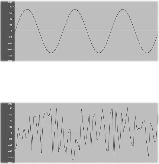
Appendix B Synthesizer Basics 473
Sound basics
Sound basics overview
Prior to considering any of the sound-generating components you will nd in a synthesizer, it’s
important that you understand sound itself.
Technically, sound is the conversion of physical energy—such as a hand clap—to an air pressure
disturbance. This change in air pressure is transmitted as a series of vibrations—a sound wave—
through the air. Sound vibrations can also be transmitted through other matter, such as a wall or
oor.
If the vibrations follow a periodic pattern, the sound is said to have a waveform.
The gure above shows an oscillogram—a graphical representation—of a sine wave, the
simplest and purest kind of waveform.
If the vibrations do not follow a discernible pattern, the sound is called noise.
A repetition of a waveform—each peak and trough in the oscillogram—is known as a cycle. The
number of cycles that occur per second determines the basic pitch of the waveform—commonly
known as the frequency. Most instruments provide an oscillator frequency control, measured in
Hertz (Hz), that determines the number of cycles per second—and therefore the basic pitch of
your sound.
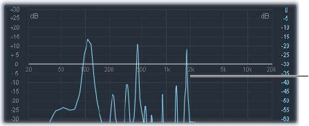
Appendix B Synthesizer Basics 474
Tones, overtones, harmonics, and partials
The base, or core, frequency of a sound is known as its fundamental tone.
The waveforms of all sounds, apart from a basic sine wave, consist of the fundamental tone and
many other tones of dierent frequencies.
Nonfundamental tones that are whole-number multiples of the fundamental tone are known
as overtones or harmonics. (A tone with a frequency that is a fraction of the fundamental tone is
referred to as a subharmonic.)
•The fundamental tone is referred to as the rst harmonic. This is generally louder than the
other harmonics.
•A tone played at twice the frequency of the rst harmonic is called the second harmonic.
•A tone played at four times the frequency of the rst harmonic is called the fourth harmonic,
and so on.
Each of these harmonics has a timbral quality that is dierent from that of the fundamental tone.
In general, harmonics that can be multiplied or divided by a whole number, such as octaves,
odd-numbered or even-numbered harmonics, and so on, sound more “musical.”
Tones that cannot be multiplied or divided by a whole number are known as inharmonic
overtones, or partial tones. When you combine a number of these inharmonic overtones, it tends
to sound “noisy.”
Nonfundamental tones that are multiplied by fractional amounts—not whole numbers—are
called partials.
The frequency spectrum
A fundamental tone, when combined with various harmonics of dierent levels, is perceived
as a sound. The level relationships between these sonic elements change over time (controlled
by envelopes, as described in Amplier envelope overview). The combination of a number of
harmonics is referred to as the harmonic spectrum or, more commonly, the frequency spectrum.
The frequency spectrum shows all individual sonic elements in a sound. It is shown low to high,
and runs from left to right over time. The respective levels of all harmonics are reected vertically,
with taller spikes indicating higher levels.
Frequency spectrum
graphic of an organ sound
The illustration shows the level and frequency relationships between the fundamental tone
and the harmonics at a particular moment in time. These relationships constantly change over
time, which results in continuous changes to the frequency spectrum and, therefore, changes to
the sound.
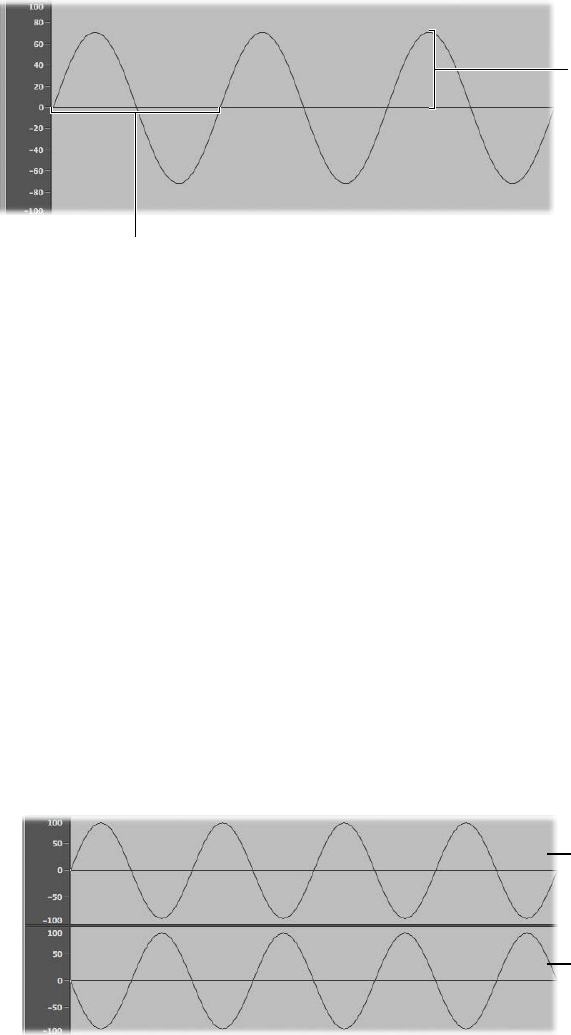
Appendix B Synthesizer Basics 475
Other waveform properties
In addition to frequency, other properties of sound waves include amplitude, wavelength, period,
and phase.
Amplitude
Wavelength
•Amplitude: The amplitude of a waveform indicates the amount of air pressure change. It can
be measured as the maximum vertical distance from zero air pressure, or “silence” (shown as a
horizontal line at 0 dB in the illustration). Put another way, amplitude is the distance between
the horizontal axis and the top of the waveform peak, or the bottom of the waveform trough.
•Wavelength: The wavelength is the distance between repeating cycles of a waveform of a
given frequency. The higher the frequency, the shorter the wavelength.
•Period: The wave period is the amount of time it takes to complete one full revolution of a
waveform cycle. The higher and faster the frequency, the shorter the wave period.
•Phase: Phase compares the timing between waveforms and is measured in degrees—from 0 to
360.
When two waveforms begin at the same time, they are said to be in phase or phase aligned.
When a waveform is slightly delayed in comparison to another waveform, the waveforms are
said to be out of phase.
Note: It is dicult to discern a constant phase dierence over the entire wave period, but if
the phase of one of the waveforms changes over time, it will become audible. This is what
happens in common audio eects such as anging and phase shifting.
When you play two otherwise identical sounds out of phase, some frequency components—
harmonics—can cancel each other out, thereby producing silence in those areas. This is known
as phase cancelation, and it occurs where the same frequencies intersect at the same level.
Phase: 180°
Phase: 0°
Appendix B Synthesizer Basics 476
Fourier theorem and harmonics
According to the Fourier theorem, every periodic wave can be seen as the sum of sine
waves with certain wave lengths and amplitudes, the wave lengths of which have harmonic
relationships—that is, ratios of small numbers. Translated into more musical terms, this means
that any tone with a certain pitch can be regarded as a mix of sine tones consisting of the
fundamental tone and its harmonics, or overtones. For example, the basic oscillation—the
fundamental tone or rst harmonic—is an “A” at 220 Hz, the second harmonic has double the
frequency (440 Hz), the third harmonic oscillates three times as fast (660 Hz), the next harmonics
four and ve times as fast, and so on.
Synthesizer fundamentals
Sound synthesis is the electronic production of sounds—starting from basic properties such as
sine tones and other simple waves.
Synthesizers are so named because they can emulate, or synthesize, a wide variety of
sounds—such as the sound of another instrument, a voice, a helicopter, a car, or a barking
dog. Synthesizers can also produce sounds that don’t occur in the natural world. The ability
to generate tones that cannot be created in any other way makes the synthesizer a unique
musical tool.
The simplest form of synthesizer would be a basic sine wave generator that provided little or no
control over pitch. Such a synthesizer would not be able to synthesize anything except a sine
wave. Combining multiple sine generators with pitch control, however, can produce interesting
and useful tones.
In a synthesizer, the task of tone generation falls to a component known as an oscillator. Most
synthesizer oscillators generate harmonically rich waveforms such as sawtooth, triangle, square,
and pulse waves, in addition to sine waves. These waveform names are based on the resemblance
of their respective shapes to a tooth on the blade of a saw, to a triangle, to a square, and so on.
For information about the most common synthesizer waveforms, see Oscillators on page 480.
Sculpting the fundamental tone and related harmonics into another sound is achieved by
routing the signal from one component, also known as a module, to another in the synthesizer.
Each module performs a dierent job that aects the source signal.
In a modular synthesizer, signal routing is achieved by physically cabling modules to each other.
In most modern synthesizers the signal routing between modules is internally prewired and is
typically changed using switches, knobs, and other controls.
For a discussion of synthesizer components and their interaction with each other to control and
shape sound, see How subtractive synthesizers work on page 478.
Synthesizers have existed far longer than you might imagine. In the days that preceded the
use of digital technology, all electronic synthesizers were analog. Prior to the use of electricity,
synthesizers were mechanical. There are signicant dierences between analog and digital
synthesizers:
•Analog: An analog synthesizer combines voltage-controlled circuits—such as oscillators, lters,
and ampliers—to generate and shape sounds. The amount of voltage is typically related
directly to the waveform pitch, with higher voltages equaling higher pitches.
•Digital: In a digital synthesizer, the signal ow is digital. Binary descriptions of the signal—a
string of zeros and ones—are fed from one algorithm to another.
Appendix B Synthesizer Basics 477
•Hybrid analog and digital synthesizers: Some synthesizer designs feature digital oscillators
that generate signals—using binary descriptions of waveforms. The digital oscillator signal is
then sent to analog lters and ampliers. The main advantage of this approach is that digital
oscillators don’t drift in pitch, which is a common problem in analog oscillators.
•Virtual analog: A virtual analog synthesizer is a digital synthesizer that mimics the architecture,
features, and peculiarities of an analog synthesizer. The behaviors and functions of the
oscillators, lters, and other modules that you would nd in an analog synthesizer are
emulated by computer algorithms.
ES1 is a virtual analog synthesizer. Its virtual signal ow is that of a typical analog synthesizer, but
all components and signal processing—the virtual oscillators, lters, and so on—are calculated
by the central processing unit (CPU) of your computer.
ES1 emulates some of the idiosyncrasies of particular analog circuits—in cases where they tend
to sound nice—such as high oscillator levels overdriving the lter. Other analog synthesizer
phenomena, such as slowly drifting out of tune (as the instrument heats up), are not simulated.
Virtual analog synthesizers have other advantages over their analog counterparts as well. They’re
programmable, which means that you can save sound settings; they can be automated, so you
can record and play back fader and knob movements; and they are often multitimbral, which
allows you to play dierent sounds at the same time, on dierent instrument channels. Aspects
such as polyphony—the ability to play multiple notes—and velocity sensitivity are found in
most virtual analog synthesizers but in very few analog instruments.
Appendix B Synthesizer Basics 478
Subtractive synthesizers
How subtractive synthesizers work
There are many approaches to sound creation with a synthesizer. (See Other synthesis methods
overview on page 492.) There are also numerous dierences between synthesizer models, but
most follow a fundamentally similar architecture and signal ow that is based on subtractive
synthesis principles.
According to legend, when Michelangelo was asked how he managed to carve David out of a
block of stone, he replied, “I just cut away everything that doesn’t look like David.”
In essence, this is how subtractive synthesis works. You lter, or cut away, parts of the sound that
you don’t want to hear. In other words, you subtract parts of the frequency spectrum, consisting
of the fundamental tone and associated harmonics.
Subtractive synthesis assumes that an acoustic instrument can be approximated with a simple
oscillator that can produce waveforms with dierent frequency spectrums. The signal is sent
from the oscillator to a lter that represents the frequency-dependent losses and resonances in
the body of the instrument. The ltered (or unltered) signal is shaped over time by the amplier
section of the synthesizer.
The distinctive timbre, intonation, and volume characteristics of a real instrument can
theoretically be recreated by combining these components in a way that resembles the natural
behavior of the instrument you are trying to emulate.
In reality, however, subtractive synthesizers aren’t perfect at emulating real-world instruments. No
synthesized clarinet is going to be mistaken for a real clarinet—particularly when compared to
samplers like the EXS24 mkII, which are able to recreate real instruments far more convincingly
by using multigigabyte sound libraries.
The true strength of subtractive synthesizers is that they oer a unique sound palette of
their own.
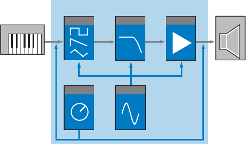
Appendix B Synthesizer Basics 479
Subtractive synthesizer components
The front panel of most subtractive synthesizers provides similar signal-generating and
processing modules—coupled with a number of modulation and control modules. The signal-
generating and processing modules typically run from left to right, mirroring the synthesizer’s
signal ow.
Output
ModulatorGlobal ctrl
AmplifierFilterOscillator
Input
Basic Synthesizer
Signal-generating and processing components
•Oscillators: Generate the basic signal. This is usually a waveform that is rich in harmonics (see
Oscillators on page 480). Many synthesizers provide more than one oscillator, and almost all
synthesizer oscillators can generate several waveform types.
•Filter section: Used to alter the basic signal by ltering out (removing) portions of the
frequency spectrum. Many synthesizers have a single lter that is applied universally to
all oscillator signals. Multioscillator synthesizers can provide multiple lters, allowing each
oscillator signal to be ltered in a dierent way (see Filters overview on page 483).
•Amplier section: Used to control the level of the signal over time. The amplier has a module
known as an envelope, which is divided into several elements that provide level control for
the beginning, middle, and end portions of your sound. Simple synthesizers generally have
a single envelope, which is used to control the oscillator (and lter) over time. More complex
synthesizers can provide multiple envelopes (see Amplier envelope overview on page 486).
Modulation and control components
•Modulators: Used to modulate the signal-generating and processing components. Modulations
can be machine-based—automatically generated by a synthesizer component—or can be
manually activated by using the modulation wheel, for example. Most synthesizers have a
component called an LFO (low frequency oscillator) to provide a waveform that modulates the
signal. See Modulation overview on page 488.
•Global controls: Set the overall characteristics of your synthesizer sound, such as glides
between notes, pitch bends, and monophonic or polyphonic playback (see Global controls on
page 491).

Appendix B Synthesizer Basics 480
Oscillators
The audio signal of a synthesizer is generated by the oscillator. You can choose from a selection
of waveforms that contain various types and amounts of harmonics. The level relationships
between the fundamental tone and the harmonics of the chosen waveform are responsible for
the basic sound color or timbre.
Waveform types
•Sine wave: Clean and clear-sounding, a sine wave contains only the rst harmonic; in other
words, it is the fundamental tone. The sine wave, used alone, can create “pure” sounds like
whistles, the sound of wet ngers on the rim of a glass, tuning forks, and so on.
•Sawtooth wave: Clear and bright-sounding, a sawtooth wave contains both odd and even
harmonics, as well as the fundamental tone. It is ideal for creating string, pad, bass, and
brass sounds.
•Square and pulse waves: Hollow and woody-sounding, a square wave can contain a wide range
of odd harmonics, as well as the fundamental tone. It is useful for creating reed instruments,
pads, and basses. It can also be used to emulate kick drums, congas, tom-toms, and other
percussive instruments—often when blended with another oscillator waveform, such as noise.
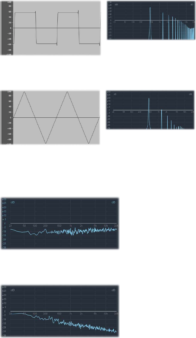
Appendix B Synthesizer Basics 481
The square wave can be reshaped to make the waveform cycles, or pulses, more rectangular,
by using a pulse width modulation (PWM) control. The more rectangular the wave becomes,
the more nasal it sounds. When modulated in this way, the square wave is known as a pulse
wave, and contains fewer harmonics. It can be used for reeds, basses, and brass sounds.
•Triangle wave: A triangle wave contains only odd harmonics, as well as the fundamental tone.
The triangle wave’s higher harmonics roll o faster than those of a square wave, making the
triangle wave sound softer. It is ideal for creating ute sounds, pads, and vocal “oohs.”
•Noise: white, pink and red, blue: Noise is useful for emulating percussive sounds, such as snare
drums, or wind and surf sounds. There are more noise wave colors than those listed, but they
are rarely found in synthesizers.
•White noise: The most common noise waveform found on synthesizers. White noise contains
all frequencies—at full level—around a center frequency.
•Pink and red noise: These noise colors also contain all frequencies, but they are not at full
level across the frequency spectrum. Pink noise decreases the level of higher frequencies by
3 dB per octave. Red noise decreases the level by 6 dB per octave.
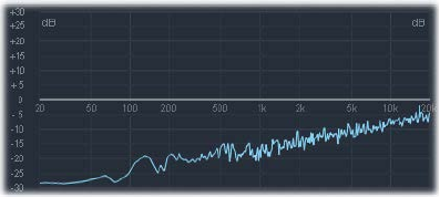
Appendix B Synthesizer Basics 482
•Blue noise: Blue noise is inverse pink noise, and increases the level of all frequencies in higher
octaves by 3 dB.
You can deform the basic waveforms to create new waveforms, which results in a dierent
timbre, or tonal color, thus expanding the palette of sounds you can create.
There are many ways to reshape a waveform, the most common of which is changing the pulse
width of a square wave. Other ways include changing the phase angle, moving the start point of
a waveform cycle, or combining multiple waveforms in multioscillator synthesizers.
When waveforms are reshaped in these and other ways, the relationships between the
fundamental tone and other harmonics change, thus altering the frequency spectrum and the
basic sound being produced.

Appendix B Synthesizer Basics 483
Filters
Filters overview
The purpose of the lter in a subtractive synthesizer is to remove portions of the signal—the
frequency spectrum—sent from the oscillators. After being ltered, a brilliant-sounding sawtooth
wave can become a smooth, warm sound without sharp treble.
The lter sections of most subtractive synthesizers contain two primary controls known as cuto
frequency—often abbreviated to cuto—and resonance. Other common lter parameters are
drive and slope. The lter section of most synthesizers can be modulated by envelopes, LFOs, the
keyboard, or other controls such as the modulation wheel.
Filter types
There are several lter types. Each has a dierent eect on various portions of the frequency
spectrum:
Highpass Band Reject Lowpass
•Highpass lter: High frequencies are passed; low frequencies are attenuated.
•Lowpass lter: Low frequencies are passed; high frequencies are attenuated.
•Bandpass lter: Only frequencies within a frequency band are passed.
•Band reject lter: Only frequencies within a frequency band are attenuated.
•Allpass lter: All frequencies in the spectrum are passed, but the phase of the output
is modied.

Appendix B Synthesizer Basics 484
Cuto frequency
The cuto frequency, or cuto, determines where the signal is cut o. Simpler synthesizers have
only lowpass lters. If a signal contains frequencies that range from 20 to 4000 Hz and the cuto
frequency is set at 2500 Hz, frequencies above 2500 Hz are ltered. The lowpass lter allows
frequencies below the cuto point of 2500 Hz to pass through unaected.
The gure below shows a sawtooth wave. The lter is open, with cuto set to its maximum value.
In other words, this waveform is unltered.
The gure below shows a sawtooth wave with the lter cuto near a 50% value. This lter setting
results in suppression of the higher frequencies and a rounding of the edges of the sawtooth
waveform, making it resemble a sine wave. This setting makes the sound softer and less “brassy.”
This example illustrates how using a lter to cut away portions of the frequency spectrum alters
the waveform shape, thus changing the timbre of the sound.

Appendix B Synthesizer Basics 485
Resonance
The resonance control emphasizes or suppresses signals around the cuto frequency.
The gure below shows an ES1 sawtooth wave with a high resonance setting and the cuto
frequency set to 660 Hz.
This resonant lter setting results in much brighter and harsher signals close to the cuto
frequency. Frequencies below the cuto point are not aected.
The result of using lter resonance is a change in the basic waveform shape and, therefore, the
timbre of the sound.
Very high lter resonance settings can cause the lter to self-oscillate, resulting in the lter
generating an audible sine wave.
Filter drive
Filter drive adds an amount of gain to the waveform as it enters the lter—an input gain
control—overdriving the lter and distorting the waveform. This waveform distortion changes
the timbre of the sound, making it much harsher.
The gure shows an unltered sawtooth wave, with drive set to a value of 80%. Note the wave
cycles touching the oor and ceiling of the lter’s dynamic range.
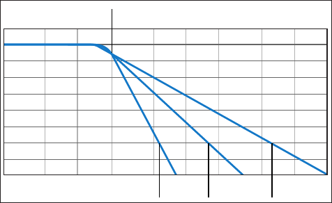
Appendix B Synthesizer Basics 486
Filter slope
A lter will cut o the signal at the cuto frequency you set. This cuto doesn’t happen abruptly
but rather at a given slope, which is measured in decibels (dB) of gain reduction per octave. You
can dene how steep the “cli” is at the cuto point by choosing a severe or gentle slope.
Cutoff frequency
24 dB/Oct 6 dB/Oct12 dB/Oct
Envelopes in the amplier
Amplier envelope overview
The amplier module of a synthesizer is responsible for controlling the level, or loudness, of the
signal over time.
Consider the sound of a violin, for example. The sound slowly ramps up to a peak, or maximum,
level as the bow is dragged across a string, then it is sustained for a period until the bow is
moved away from the string, at which point it cuts o abruptly.
In contrast to the violin example, hitting a snare drum with a drumstick results in a very fast
peak level with no sustain portion, then the sound immediately dies out—although there will be
some decay, the time it takes to fall from the peak level.
These two sounds clearly have dierent characteristics over time.
Synthesizers emulate these sonic characteristics by providing control over dierent parts—the
beginning, middle, and end—of a sound’s level over time. This control is achieved using a
component called an envelope generator.
Note: Envelope generators are not limited to controlling signal amplitude. They can also control
the rise and fall of the lter cuto frequency or they can modulate other parameters. In short,
envelope generators can be used as a modulation source—or as a “remote control” for a given
parameter. See Modulation overview.
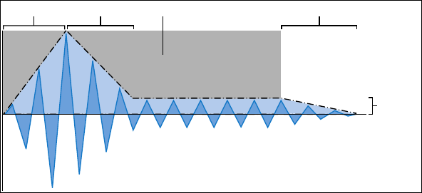
Appendix B Synthesizer Basics 487
Attack, decay, sustain, and release
The oscillogram of a percussive tone shown below illustrates the level rising immediately to the
top of its range and then decaying. If you drew a box around the upper half of the oscillogram,
you could consider it the “envelope” of the sound—an image of the level as a function of time.
The role of the envelope generator is to set the shape of this envelope.
Attack Decay Release
Sustain
Time that the key is held
The envelope generator usually features four controls—Attack, Decay, Sustain, and Release,
commonly abbreviated as ADSR.
Envelope controls
•Attack: Sets the time it takes for the signal to rise from an amplitude of 0 to 100% (full
amplitude).
•Decay: Sets the time it takes for the signal to fall from 100% amplitude to the designated
sustain level.
•Sustain: Sets the steady amplitude level produced when a key is held down.
•Release: Sets the time it takes for the sound to decay from the sustain level to an amplitude of
0 when the key is released.
Note: If a key is released during the attack or decay stage, the sustain phase is usually skipped.
A sustain level of 0 produces a piano-like—or percussive—envelope, with no continuous steady
level, even when a key is held.
Appendix B Synthesizer Basics 488
Modulation
Modulation overview
Without modulation, sounds tend to be uninteresting and fatiguing to the ear. They also sound
synthetic, rather than natural, in the absence of some type of sonic modulation. Vibrato is a
type of modulation commonly used by orchestral string players to add animation to their
instrument’s pitch.
To make sounds less static, you can use a range of synthesizer controls to modulate basic sound
parameters. To this end, many synthesizers, including ES1, ES2, and EXS24 mkII sampler, provide a
modulation router.
The router enables you to direct, or route, one or more modulation sources (the parameter or
control that is modulating another parameter) to one or more modulation targets (the parameter
being modulated).
You can aect modulation targets, such as oscillator pitch or lter cuto frequency, by using
modulation sources that include the following:
•Velocity modulation: You can modulate a target in dierent ways with the impact of your
keyboard playing (harder or softer). The most common example of modulation controller use
is a velocity-sensitive keyboard, set to control the lter and level envelopes. The harder you
strike the notes, the louder and brighter the sound is.
•Key scaling: You can modulate a target in dierent ways by adjusting the position you play on
the keyboard (low or high notes).
•Controls: You can use controls such as the modulation wheel, ribbon controllers, or pedals
attached to your keyboard.
•Automatic modulation: You can use envelope generators or LFOs to modulate
signals automatically.
Modulation sources can be—and often are—triggered by something you’ve done, such as
playing a note on the keyboard, or moving the modulation wheel.
The modulation wheel, pitch bend ribbons, foot pedals, keyboard, and other input options are
referred to as modulation controllers, MIDI controllers, or just controllers.

Appendix B Synthesizer Basics 489
Modulation routing in ES1 and ES2
ES1 and ES2 provide an easy way to route a control—a modulation source—to part of the sound
engine—a modulation target.
ES1 modulation routing
You create an ES1 modulation routing by selecting a modulation target in the left or right
column of buttons in the Router section.
•You use the left column to set a modulation target that can be controlled, in amount, with the
modulation wheel of your keyboard.
•The target you select in the right column will dynamically respond to keyboard velocity.
•The amount, or range, of this modulation is determined by the two arrows shown in the
sliders, Int via Whl and Int via Vel. The upper arrow determines the maximum amount of
modulation, and the lower arrow determines the minimum amount of modulation.
ES2 modulation routing
ES2 provides ten modulation routings, in columns. Each routing column is quite similar to the
modulation controls found in ES1.
In the rst routing column shown above:
•The modulation target is Pitch123. The pitch—the Frequency parameter—of Oscillators 1, 2,
and 3 is aected by LFO2, the modulation source.
•LFO2 is the modulation source. The two arrows to the right of the column indicate the
modulation amount. To make the modulation more intense, drag the upper and/or lower
arrows up or down, thereby increasing the range of the modulation amount. The upper
arrow determines the maximum amount of modulation, and the lower arrow determines the
minimum amount of modulation.
•The via control is the ModWhl. Its range is determined by the sliders to the right of the
channel. The amount of modulation is directly controlled with the modulation wheel of your
keyboard. When the modulation wheel is at the minimum setting, at the bottom of its travel,
the amount of oscillator pitch modulation is minimal, or o (no modulation). As you move the
modulation wheel upward, the frequency of all three oscillators is directly controlled by the
LFO (within the range determined by the sliders).
Appendix B Synthesizer Basics 490
Common modulation sources
The main envelope generator of the synthesizer not only controls levels over time, but it also is
often used to modulate other sound parameters when you press or release keyboard keys. Many
synthesizers, such as ES2, feature multiple envelope generators.
The most common use of envelope modulation is to control the lter cuto and resonance
parameters with the keyboard velocity or keyboard scaling modulation sources (see Modulation
overview on page 488).
A modulation source found on nearly all synthesizers is the LFO (low frequency oscillator). This
oscillator is used only as a modulation source and does not generate any audible signals that
form part of your actual synthesizer sound, because it’s too low to be heard. It can, however,
aect the main signal by adding vibrato, lter sweeps, and so on.
Common LFO controls
•Waveform: Allows you to choose the type of waveform—triangle waves and square waves
are common.
•Triangle waves are useful for lter sweeps—slow changes to the lter cuto frequency—or
when simulating an ambulance siren—slow changes to the oscillator frequency.
•The square waveform is useful for rapid switches between two dierent pitches, such as
vibratos or octaving.
•Frequency/Rate: Determines the speed of the waveform cycles produced by the LFO. When it
is set to low values, very slow ramps are produced, making it easy to create sounds such as
ocean waves rolling in—when white noise is chosen as the waveform in the main oscillator.
•Sync mode: Allows you to choose between free running—a user-dened LFO rate—or
synchronization with an external tempo source, such as a host application.
•LFO Envelopes: The LFO can also be controlled with an envelope generator in some
synthesizers. For example, imagine a sustained string section sound where vibrato is
introduced a second or two into the sustained portion of the sound. If this can happen
automatically, it allows you to keep both hands on the keyboard. Some synthesizers include a
simple LFO envelope generator for this purpose. Often, this envelope consists only of an attack
parameter—some may also include decay or release options. These parameters perform in the
same way as the amplitude envelope parameters (see Attack, decay, sustain, and release on
page 487), but they are limited to control of LFO modulations.
Appendix B Synthesizer Basics 491
Global controls
Global controls aect the overall output signal of your synthesizer.
Common global controls
•Level: Sets the overall loudness of your sound. This control is the master output volume control
of your synthesizer.
•Glide (portamento): Sets the amount of time that it takes for one note pitch to slide up or down
to another note pitch. This control is useful for emulating wind instruments that slide from
note to note, rather than move directly to another clear and distinct pitch.
•Bender/bend range: Bends the pitch—the oscillator frequency—up or down. This control is
generally hard-wired to a pitch bend wheel on a keyboard. As the name suggests, moving the
wheel up or down from its centered position bends the pitch up or down. The Bender/Bend
Range parameter usually has an upper and lower limit of one octave but is typically set to
around three semitones up or down. This setting is ideal for emulating small (or extreme) pitch
uctuations that occur in some instruments—such as when moving between notes with a
trumpet, or bending the strings during a guitar solo.
•Voices: Sets an upper limit to the number of notes that can be played at a given time.
Producing notes simultaneously is known as the polyphony—literally, “many voices”—of the
instrument. The Voices parameter sets an upper limit to the number of notes that can be
produced simultaneously.
•Unison: Used to “stack” voices—with the unison voice being heard one octave above the
frequency of the played note. Because two voices are being used when you play a note,
unison has two eects—it makes the sound richer and fuller, and it halves the polyphony.
•Trigger mode: Determines how the polyphony of the instrument is handled when the number
of notes played exceeds the number of available voices. Trigger mode also allows you to
assign legato mode. Essentially, this control changes the way the synthesizer responds to your
playing technique and is invaluable when you are emulating monophonic instruments, such
as utes, clarinets, and trumpets. When you use the trigger mode control and assign a last
note priority, a playing note will be cut o by playing another note.
•Last note priority: When new notes are triggered while all voices are playing, the synthesizer
frees up polyphony (voices) by ending the notes played earliest. This is the default trigger
mode of the included synthesizers when in a monophonic mode.
•First note priority: Notes played earlier are not stopped. In this mode you need to stop playing
notes in order to play a new one after you have reached the limit of the polyphony (voices)
of the instrument.
Note: The Trigger Mode parameter can also allow you to set priorities for lower- or higher-
pitched notes when playing monophonically (one voice at a time) in some synthesizer designs.
There are many other global controls found on dierent synthesizer models that have an impact
on your overall sound.
Appendix B Synthesizer Basics 492
Other synthesis methods
Other synthesis methods overview
There are many ways to create sounds, using dierent technologies and approaches to
synthesis. This section covers all the main methods, with reference to the included instruments
where applicable.
Many of the methods described incorporate at least some elements of the subtractive synthesis
design. See How subtractive synthesizers work. The most common modern approach is based on
samples of real instruments and sounds.
Sample-based synthesis
Sample-based synthesis, which is sometimes known as Pulse Code Modulation (PCM), or sampling
and synthesis (S&S) synthesis, is dierentiated from subtractive synthesis mainly by the use of
samples in place of oscillator waveforms.
The samples—digital recordings of existing sounds—are mapped across the keyboard. Typically,
each sample is mapped to a note in the center of a keyboard range that spans a few notes that
are unique to that sample. The reason for this limited range of notes is that samples tend to
sound much less like the source sound if played more than a few notes higher or lower than the
original pitch—due to the relationship between the pitch and playback speed of samples.
The pitch of each sample isn’t changed with a frequency control, unlike the oscillator waveform
of a synthesizer. Rather, a sample is played back at a faster or slower speed to alter its pitch,
which has a corresponding impact on the sample playback time. For example, a sample played
back at twice the speed requires half the time to play through.
EXS24 mkII is a sample player that can be used much like a sample-based synthesizer, due to the
subtractive synthesis features that it oers.
Popular instruments that use this synthesis approach include Korg’s M1, O1/W, and Triton; the
Roland JV/XP instruments; Yamaha’s Motif series; and many others.
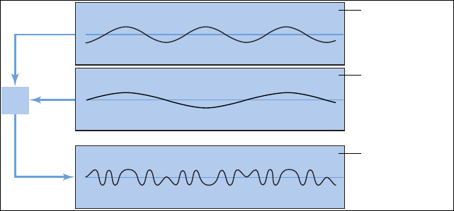
Appendix B Synthesizer Basics 493
Frequency modulation (FM) synthesis
FM synthesis uses a modulator oscillator and a sine wave carrier oscillator. The modulator
oscillator modulates the frequency of the carrier oscillator within the audio range, thus
producing new harmonics. These harmonics are known as sidebands.
FM
Modulator oscillator
Carrier oscillator
Resulting waveform
Typically, FM synthesizers don’t incorporate a lter. You can generate some subtractive
synthesizer style sounds with FM synthesis, but it is dicult to recreate the sound of a resonant
subtractive synthesizer lter using this method. FM synthesis is extremely good, however, at
creating sounds that are dicult to achieve with subtractive synthesizers—sounds such as bell
timbres, metallic tones, and the tine tones of electric pianos. Another strength of FM synthesis is
punchy bass and synthetic brass sounds.
The EFM1 and Retro Synth FM synthesizers can produce many of the classic FM sounds made
famous by Yamaha’s DX series of synthesizers. The DX7, sold from 1983 to 1986, remains the most
commercially successful professional-level hardware synthesizer ever made.
ES2 also features some FM techniques that allow you to modulate one oscillator with another.
You can use these FM techniques to partially bridge the gap between the digital sound of
FM synthesis and the fat analog sound that ES2 is noted for.
Appendix B Synthesizer Basics 494
Component modeling synthesis
Also known as physical modeling, this synthesis method uses mathematical models to simulate
instruments. Parameters are used to describe an instrument’s physical characteristics, such as the
materials the instrument is made of, the dimensions of the instrument, and the environment it
is played in—under water, or in the air, for example. Equally important are descriptions of how
the player would interact with the instrument—whether it is played by plucking, bowing, or
strumming strings; by hitting it with sticks; by placing ngers on sound holes; and so on.
To model a drum sound, for example, the following aspects need to be taken into account.
Of primary importance is the actual drum strike—how hard it is and whether the drumhead
is struck with a wooden stick, a mallet, a beater, and so on. The properties of the drumhead
(the skin or membrane) include the kind of material, its degree of stiness, its density,
its diameter, and the way it is attached to the shell of the drum. The volume of the drum
cylinder itself, its material, and the resonance characteristics of all of the above need to be
mathematically described.
To model a violin, you need to take into account the bow against the string, the bow width and
material, the bow tension, the string material, the string density, the string tension, the resonance
and damping behavior of the strings, the transfer of string vibrations through the bridge
(materials, size, and shape of the bridge), and the materials, size, and resonance characteristics
of the violin body. Further considerations include the environment that your modeled violin is
played in and the playing style—“hammering” or tapping with the bow as opposed to drawing it
across the strings.
The Sculpture component modeling synthesizer can produce convincing recreations of acoustic
(and electronic) instruments. It is also exceptionally good at creating atmospheric, constantly
evolving pad sounds. Other instruments that include physical modeling components and
techniques are Ultrabeat, Vintage B3, Vintage Clav, and Vintage Electric Piano.
Appendix B Synthesizer Basics 495
Wavetable, Vector, and Linear Arithmetic synthesis
Wavetable synthesis uses a number of dierent single-cycle waveforms, laid out in what is known
as a wavetable.
Playing a note on the keyboard triggers a predetermined sequence of waves. In general, this is
not a stepped transition but rather a smooth blend from one waveform into another, resulting
in a constantly evolving waveform. Multiple wavetables can also be used simultaneously—
either played one after the other, or blended together—resulting in more harmonically
complex waveforms.
A single wavetable can emulate lter cuto with a series of bright, less bright, then dull-sounding
waveforms played in sequence—which resembles a reduction of the lter cuto frequency in a
subtractive synthesizer.
Wavetable synthesis isn’t well-suited for emulating acoustic instruments. It is noted for producing
constantly evolving sounds; harsh and metallic, or bell-like sounds; punchy basses; and other
digital tones.
Wavetable synthesis was championed by the PPG and Waldorf instruments. The ES2 and Retro
Synth also include wavetable features.
Roland LA (Linear Arithmetic) synthesizers such as the D-50 work on a similar principle. In these
synthesizers complex sampled attack phases are combined with simple sustain or decay phases
to create a sound. In essence, this is a simple wavetable that consists of two samples.
Where LA and wavetable synthesizers dier is that the latter were designed to create new,
original, digital sounds. LA synthesizer designers, in contrast, wanted to emulate real instruments
using a minimum of memory. To achieve this goal, they combined samples of the attack phase—
the crucial part of a sound—with appropriate decay and sustain phases.
Vector synthesis—used in the Sequential Circuits Prophet-VS and Korg’s Wavestation—allows
you to move through wavetables and sequences arranged on a two-dimensional grid (two
dierent vectors, or less technically, on the X or Y axis). The main benet of this approach is
that the balance between samples and waves is achieved in real time by moving a joystick. You
can also use the ES2 to perform vector synthesis by modulating the Oscillator Mix (Triangle)
parameter with the Vector Envelope.
Appendix B Synthesizer Basics 496
Additive synthesis
Additive synthesis overview
Additive synthesis could be considered the reverse approach to subtractive synthesis. See
Sound basics overview, Tones, overtones, harmonics, and partials, and How subtractive
synthesizers work.
To obtain an insight into the additive synthesis approach, consider the fact that all sounds are a
sum of various sine tones and harmonics.
In additive synthesis, you start out with nothing and build a sound by combining multiple sine
waves of diering levels and frequencies. As more sine waves are combined, they begin to
generate additional harmonics. In most additive synthesizers, each set of sine waves is viewed
and used much like an oscillator.
Depending on the sophistication of the additive synthesizer you are using, you will either have
individual envelope control over each sine wave or you will be limited to envelope control
over groups of sine waves—one envelope per sound and its harmonics, or all odd or all even
harmonics, for example.
MainStage doesn’t provide a true additive synthesizer, but aspects of the additive synthesis
approach are used in Vintage B3 and all other drawbar organs. In Vintage B3 you start with a
basic tone and add harmonics to it, to build up a richer sound. The level relationships between
the fundamental tone and each harmonic are determined by how far you pull each drawbar
out. As Vintage B3 doesn’t provide envelope control over each harmonic, it is limited to
organ emulations.
Resynthesis
You can analyze the frequency components of a recorded sound and then resynthesize—
reconstruct—a representation of the sound using additive techniques. By calculating the
frequency and amplitude of each harmonic in the overall frequency spectrum of the sound, an
additive resynthesis system can generate a series of sine waves, with appropriate levels over time,
for each harmonic.
After the sound has been resynthesized in this fashion, you can adjust the frequency and
amplitude of any harmonic. Theoretically, you could even restructure a harmonic sound to make
it inharmonic, for example.
Appendix B Synthesizer Basics 497
Phase distortion synthesis
Phase distortion synthesis creates dierent waveforms by modifying the phase angle of a
sine wave.
In essence, you can bend a sine wave until it becomes a sawtooth wave, a triangle wave, a square
wave, and so on. The synthesizer engine beyond the waveform generators typically follows a
subtractive synthesizer design.
Phase distortion synthesis was commercially introduced in the 1984 Casio CZ series synthesizers.
Granular synthesis
The basic premise behind granular synthesis is that a sound can be broken down into tiny
particles, or grains. These sampled grains—usually no more than 10 to 50 milliseconds long—can
then be reorganized, or combined with grains from other sounds, to create new timbres.
In many respects, granular synthesis is similar to wavetable synthesis, but it works on a much
ner scale. As you might expect, this method is ideal for creating constantly evolving sounds and
truly unique tones.
The downside is that granular synthesis is extremely processor-intensive, and it wasn’t possible
to do in real time until relatively recently. For this reason, it has remained largely ignored by all
but a few in academic institutions. Today’s computers, however, have sucient processing power
to make this synthesis method a practicality, so there are a number of commercial products
now available.
Appendix B Synthesizer Basics 498
A brief synthesizer history
Precursors to the synthesizer
The earliest seeds of modern electronic synthesizers began in the twilight years of the 19th
century. In 1897, an American inventor named Thaddeus Cahill was issued a patent to protect the
principle behind an instrument known as the Telharmonium, or Dynamophone. Weighing in at
200 tons, this mammoth electronic instrument was driven by 12 steam-powered electromagnetic
generators. It was played in real time using velocity-sensitive keys and, amazingly, was able to
generate several dierent sounds simultaneously. The Telharmonium was presented to the public
in a series of “concerts” held in 1906. Christened “Telharmony,” this music was piped into the
public telephone network, because no public address systems were available at the time.
In 1919, Russian inventor Leon Theremin took a markedly dierent approach. Named after the
man who masterminded it, the monophonic Theremin was played without actually touching
the instrument. It gauged the proximity of the player’s hands as they were waved about in an
electrostatic eld between two antennae, and used this information to generate sound. This
unorthodox technique made the Theremin enormously dicult to play. Its eerie, spine-tingling—
but almost unvarying—timbre made it a favorite on countless horror movie soundtracks. R. A.
Moog, whose synthesizers would later garner worldwide fame, began to build Theremins at the
age of 19.
In Europe, Frenchman Maurice Martenot devised the monophonic Ondes Martenot in 1928. The
sound generation method of this instrument was akin to that of the Theremin, but in its earliest
incarnation it was played by pulling a wire back and forth.
In Berlin during the 1930s, Friedrich Trautwein and Oskar Sala worked on the Trautonium,
an instrument that was played by pressing a steel wire onto a bar. Depending on the
player’s preference, it enabled either innitely variable pitches—much like a fretless stringed
instrument—or incremental pitches similar to that of a keyboard instrument. Sala continued
to develop the instrument throughout his life, an eort culminating in the two-voice
Mixturtrautonium in 1952. He scored numerous industrial lms, as well as the entire soundtrack
of Alfred Hitchcock’s masterpiece The Birds, with this instrument. Although the movie does not
feature a conventional musical soundtrack, all bird calls and the sound of beating wings heard in
the movie were generated on the Mixturtrautonium.
In Canada, Hugh Le Caine began to develop his Electronic Sackbut in 1945. The design of
this monophonic instrument resembled that of a synthesizer, but it featured an enormously
expressive keyboard that responded not only to key velocity and pressure but also to
lateral motion.
The instruments discussed thus far were all designed to be played in real time. Relatively early,
however, people began to develop instruments that combined electronic sound generators
and sequencers. The rst instrument of this kind—named the Automatically Operating Musical
Instrument of the Electric Oscillation Type—was presented by the French duo Edouard Coupleux
and Joseph Givelet in 1929. This hybrid married electronic sound generation to a mechanically
punched tape control. Its name was unocially shortened to Coupleux-Givelet Synthesizer by its
builders, the rst time a musical instrument was called a “synthesizer.”
Appendix B Synthesizer Basics 499
The term was formally introduced in 1956 with the debut of the RCA Electronic Music Synthesizer
Mark I, developed by American engineers Harry F. Olson and Herbert Belar. Its dual-voice sound
generation system consisted of 12 tuning forks, which were stimulated electromagnetically. For
its time, the instrument oered relatively sophisticated signal-processing options. The output
signal of the sound generator could be monitored by loudspeakers and, amazingly, recorded
directly onto two records. A single motor powered both turntables and the control unit of
the Mark 1. The synthesizer was controlled by information punched onto a roll of paper tape,
enabling continuous automation of pitch, volume, timbre, and envelopes. It was extremely
complicated to use, it was unreliable, and spontaneous playing was impossible.
Early voltage-controlled synthesizers
With the exception of the Telharmonium, which was conceived prior to the advent of the
thermionic valve, the precursors to the modern-day synthesizer were all based on tube circuitry.
This made these instruments unwieldy and volatile. After the transistor became available in
1947/48, more rugged, smaller, and thus portable, instruments were soon to come.
At the end of 1963, American innovator R. A. (Bob) Moog met the composer Herbert Deutsch.
Deutsch inspired Moog to combine a voltage-controlled oscillator and amplier module with a
keyboard, and in 1964 the rst prototype of a voltage-controlled synthesizer was constructed.
This collaboration with the German musician prompted Moog to extend his range of modules
and to combine them into entire systems. It wasn’t until 1967, however, that Moog actually called
his diverse mix-and-match systems synthesizers.
Moog’s achievements spread by word of mouth, and Moog, always keen to elicit the feedback
of his customers, continued to add further modules to his line. Wendy Carlos’s LP release
Switched-On Bach (1968) was responsible for the breakthrough of Moog’s instruments.
The record featured Moog’s modular synthesizers and was one of the earliest commercial
multitrack recordings. The album’s success introduced the synthesizer to a wider audience and
made the name “Moog” synonymous with the instrument. Hoping to capitalize on the new
sounds that synthesizers made available, and match Carlos’s commercial success, numerous
studios, producers, and musicians acquired Moog modular synthesizers. In 1969, as many
as 42 employees produced two to three complete modular systems every week at Moog’s
production facility.
Working independently, an engineer named Donald Buchla had conceived and implemented the
concept for a modular, voltage-controlled synthesizer. This coincided with Moog’s version. Buchla
also developed his rst instruments in close cooperation with users. The inspiration for his rst
synthesizer originated with composers Morton Subotnik and Ramon Sender, of the San Francisco
Tape Music Center. Although he began working on this instrument in 1963, it didn’t make its
public debut until 1966. By design, Buchla’s instruments catered primarily to academia and avant-
garde musicians, so they never garnered the public attention and acclaim of Moog’s synthesizers.
Appendix B Synthesizer Basics 500
The Minimoog
Moog and Buchla’s voltage-controlled synthesizers were modular. One chassis, or several,
housed the power supply and the actual modules. The inputs and outputs of the modules had
to be interconnected via a confusing tangle of patch cords before the synthesizer would make
a sound. Establishing these connections properly was an art unto itself, and obtaining useful
settings on the modules required signicant expertise.
Moog realized that these modular synthesizers were too complex and expensive for the
average musician and were likely to fail if sold through traditional music retailers. In 1969,
Moog collaborated with engineers Jim Scott, Bill Hemsath, and Chad Hunt to design a compact,
portable, aordable, and easy-to-use synthesizer. After three prototypes were built, the Minimoog
Model D was released in the summer of 1970.
In contrast to previous modular synthesizers, it was neither necessary nor possible for players to
connect the modules of the Minimoog as they saw t. All of the modules’ connecting circuitry
was hard-wired at the factory. The type and number of modules was also xed. This simplied
manufacturing considerably, and cut costs dramatically. A major marketing campaign saw the
Minimoog become a huge success. Without alteration to its basic design, 13,000 Minimoogs were
sold worldwide, right up to 1981.
Appendix B Synthesizer Basics 501
Storage and polyphony
Customers weren’t entirely satised with the Minimoog and contemporary synthesizers, however.
Although musicians no longer had to contend with countless cords in order to play a synthesizer,
they still had to deal with numerous knobs and switches before they could do something as
simple as switch from one sound to another. Moreover, keyboardists were bored with playing
monophonic melody lines on synthesizers—they wanted to play chords. Although dual-voice
keyboards that connected two monophonic synthesizers were available as early as 1970,
customers wanted more.
Attempting to satisfy these demands, two schools of thought emerged in synthesizer design.
One approach called for an independent, monophonic synthesizer to be assigned to every key
on the keyboard. To this end, designers married the design principles of electronic organs to
synthesizer technology. Although this breed of instrument was fully polyphonic—all notes of
the keyboard could be heard simultaneously—it wasn’t as versatile in its control options as a
true synthesizer. The rst fully polyphonic synthesizer to feature this type of design was the
Moog Polymoog, released in 1975. Developed primarily by David Luce, it featured 71 weighted,
velocity-sensitive keys.
In the second approach to polyphonic sound generation, a synthesizer was assigned to a key
only when the key was pressed—in eect, semi-polyphony. As early as 1973, American company
E-MU Systems introduced the Modular Keyboard System Series 4050, a digital keyboard that
could be connected to up to ten monophonic synthesizers, and thus had ten-voice polyphony.
The problem with this approach was that very few people owned ten synthesizers, and the
amount of time and eort involved in programming a new sound was an overwhelming
deterrent. Digital memory was still waiting to be developed, and, once again, the evolution of
semi-polyphonic synthesizers required the qualities that only digital keyboards could provide.
The same prerequisite—digital engineering—eventually led to synthesizers that allowed sounds
to be stored. Without the benet of digital technology, early attempts at storing sounds included
some unusual solutions. For example, a synthesizer with analog programmability required a
dedicated row featuring all of the instrument’s control elements for every “memory” slot. In this
case, a selector switch accessed one of the many identical control panels and connected it to the
sound generator.
The rst synthesizer featuring storage slots implemented in this manner was the 1975 Yamaha
GX1. The control elements for the system’s storage slots were so small that they could be
adjusted only by using jeweler’s screwdrivers and complicated tools—called programmers
and comparators.
It was not until 1978 that the problem was resolved. The ve-voice polyphonic Prophet-5,
released by the American company Sequential Circuits, was the world’s rst synthesizer with
a global storage feature. All settings for each of its ve onboard monophonic synthesizers
were stored in memory slots—40 in the debut model. Moreover, all ve synthesizers shared a
single user interface, which simplied matters considerably. In spite of its initially high price,
this instrument proved extremely popular and approximately 8,000 were built up until 1985. In
addition to its digitally implemented polyphony and memory, the success of the Prophet-5 is
due to the quality of its analog sound generation system.
Appendix B Synthesizer Basics 502
Digital synthesizers
Modern digital synthesizers featuring variable polyphony, memory, and completely digital
sound generation systems follow a semi-polyphonic approach. The number of voices that
these instruments are able to generate, however, no longer depends on the number of built-in
monophonic synthesizers. Rather, polyphony depends entirely on the performance capability of
the computers that power them.
The rapid developments in the digital world are best illustrated by the following example. The
rst program that emulated sound generation entirely by means of a computer was Music I,
authored by the American programmer Max Mathew. Invented in 1957, it ran on a university
mainframe, an exorbitantly expensive IBM 704. Its sole claim to fame was that it could compute a
triangle wave, although doing it in real time was beyond its capabilities.
This lack of capacity for real-time performance is the reason why early digital technology
was used solely for control and storage purposes in commercial synthesizers. Digital control
circuitry debuted in 1971 in the form of the digital sequencer found in the Synthi 100 modular
synthesizer—in all other respects an analog synthesizer—from the English company EMS. Priced
out of reach of all but the wealthiest musicians, the Synthi 100 sequencer featured a total of
256 events.
Ever-increasing processor performance made it possible to integrate digital technology
into parts of the sound generation engine itself. The monophonic Harmonic Synthesizer,
manufactured by Rocky Mountain Instruments (RMI), was the rst instrument to do so. This
synthesizer had two digital oscillators, combined with analog lters and amplier circuits.
The Synclavier, introduced in 1976 by New England Digital Corporation (NED), was the rst
synthesizer with completely digital sound generation. Instruments like the Synclavier were based
on specialized processors that had to be developed by the manufacturers themselves. This
development cost made the Synclavier an investment that few could aord.
An alternative solution was the use of general-purpose processors made by third-party
computer processor manufacturers. These processors, especially designed for multiplication
and accumulation operations—common in audio processing tasks—are called digital signal
processors (DSPs). Peavey’s DPM-3, released in 1990, was the rst commercially available
synthesizer completely based on standard DSPs. The instrument was 16-note polyphonic and
based mainly on three Motorola 56001 DSPs. It featured an integrated sequencer and sample-
based subtractive synthesis, with factory presets and user-denable samples.
Another solution was to design synthesizers as a computer peripheral, rather than as a
standalone unit. The growing popularity of personal computers from the early 1980s made
this option commercially viable. Passport Soundchaser and the Syntauri alphaSyntauri were
the rst examples of this concept. Both systems consisted of a processor card with a standard
musical keyboard attached to it. The processor card was inserted into an Apple II computer. The
synthesizers were programmed via the Apple keyboard and monitor. They were polyphonic and
had programmable waveforms, envelopes, and sequencers. Today’s sound cards, introduced in
countless numbers since 1989, follow this concept.
Exploiting the ever-increasing processing power of today’s computers, the next evolutionary
step for the synthesizer was the software synthesizer, which runs as an application on a host
computer.
The sound card (or built-in audio hardware) is needed these days only for audio input and
output. The actual process of sound generation, eects processing, recording, and sequencing is
performed by your computer’s CPU—using the host software and instrument collection.
