Applied Concepts ACMI007 Stationary Speed Sensor II User Manual
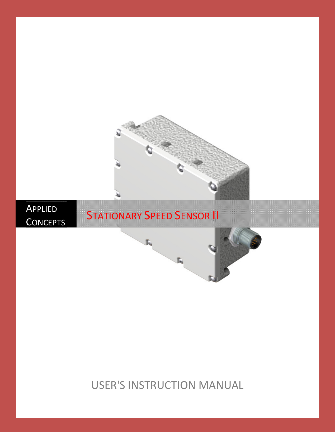
Applied Concepts Inc Stationary Speed Sensor II
UserManual.wiki
>
Applied Concepts
>
ACMI007 User Manual
user manual
Navigation menu
Upload a User Manual
Namespaces
Wiki Guide
HTML
PDF
Info
Views
User Manual
Discussion / Help
Navigation
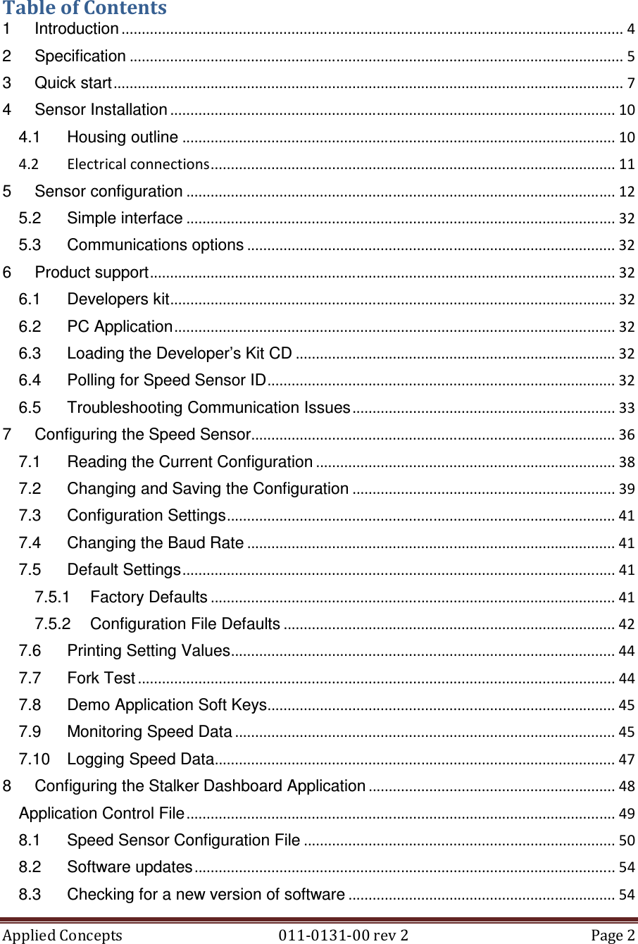
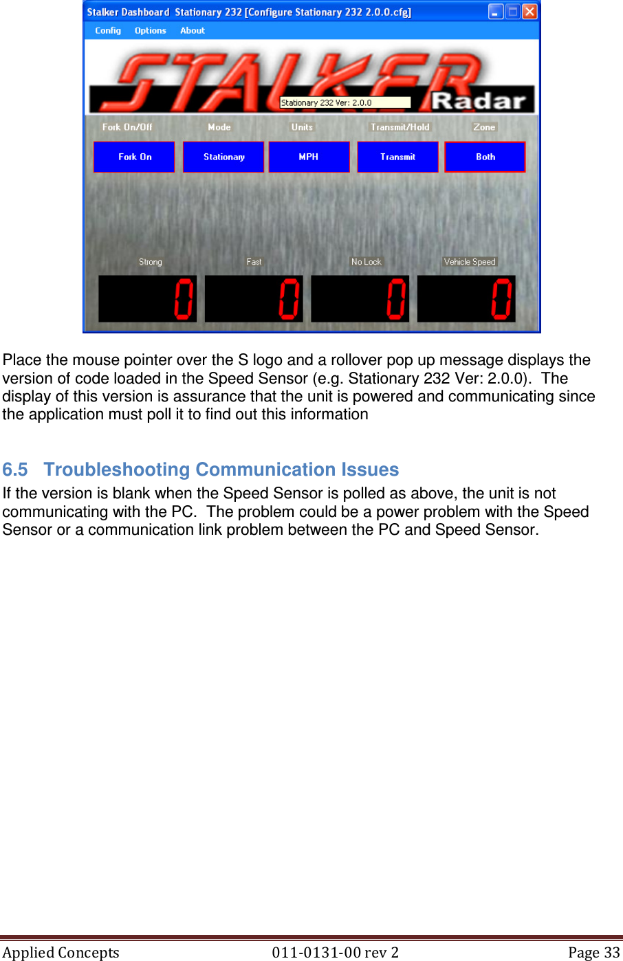
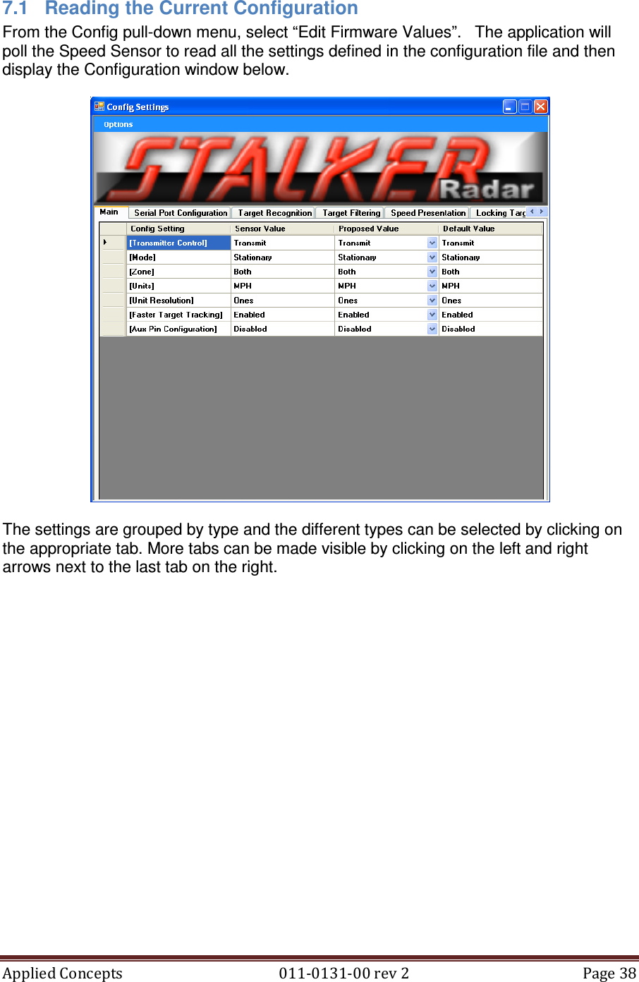
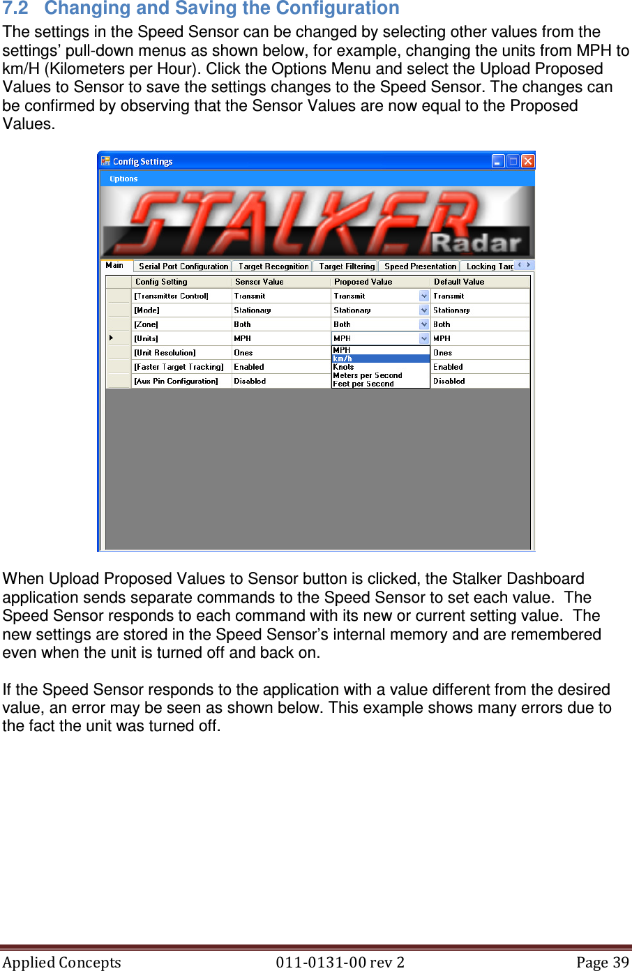
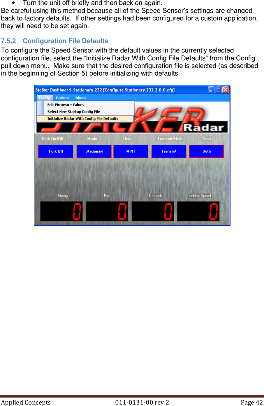
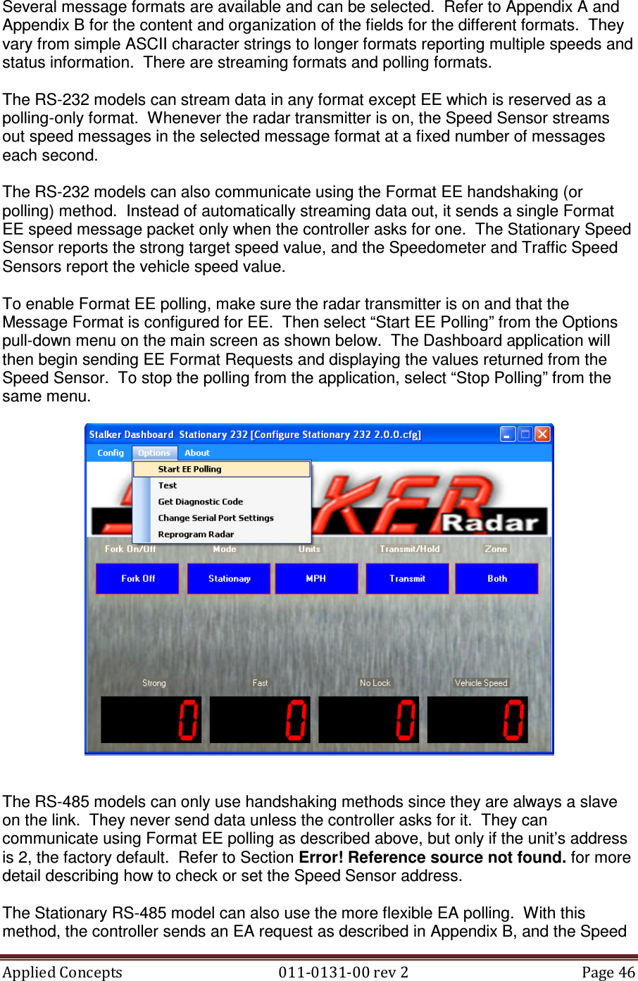
![Applied Concepts 011-0131-00 rev 2 Page 36 7 Configuring the Speed Sensor When viewing the main screen of the demo application, the name of a configuration file is displayed in the title bar (e.g. [Configure Stationary 232 2.0.0.cfg]). This file defines all of the configurable settings that are available on a particular model of Speed Sensor. Since features and settings are added and changed in different versions of software, the filename also includes the version (2.0.0) that the file’s settings apply to. The screen-shot examples in this chapter are taken from the Stalker Dashboard application. All of the configuration features and capabilities, except software upgrading, are also available with the S3-Speed Sensor PC Apps located on the Program CD. If the filename is for a different unit, open a list of other available configuration files by selecting “Select New Startup Config File” from the Config pull-down menu. The dialog box on the next page will open and allow for a selection to be made. It is important that the model and software version in the configuration filename match the model and version in the Product ID. The dialog box will contain the Sensor model and current software revision in the blue title bar.](https://usermanual.wiki/Applied-Concepts/ACMI007/User-Guide-1675608-Page-37.png)
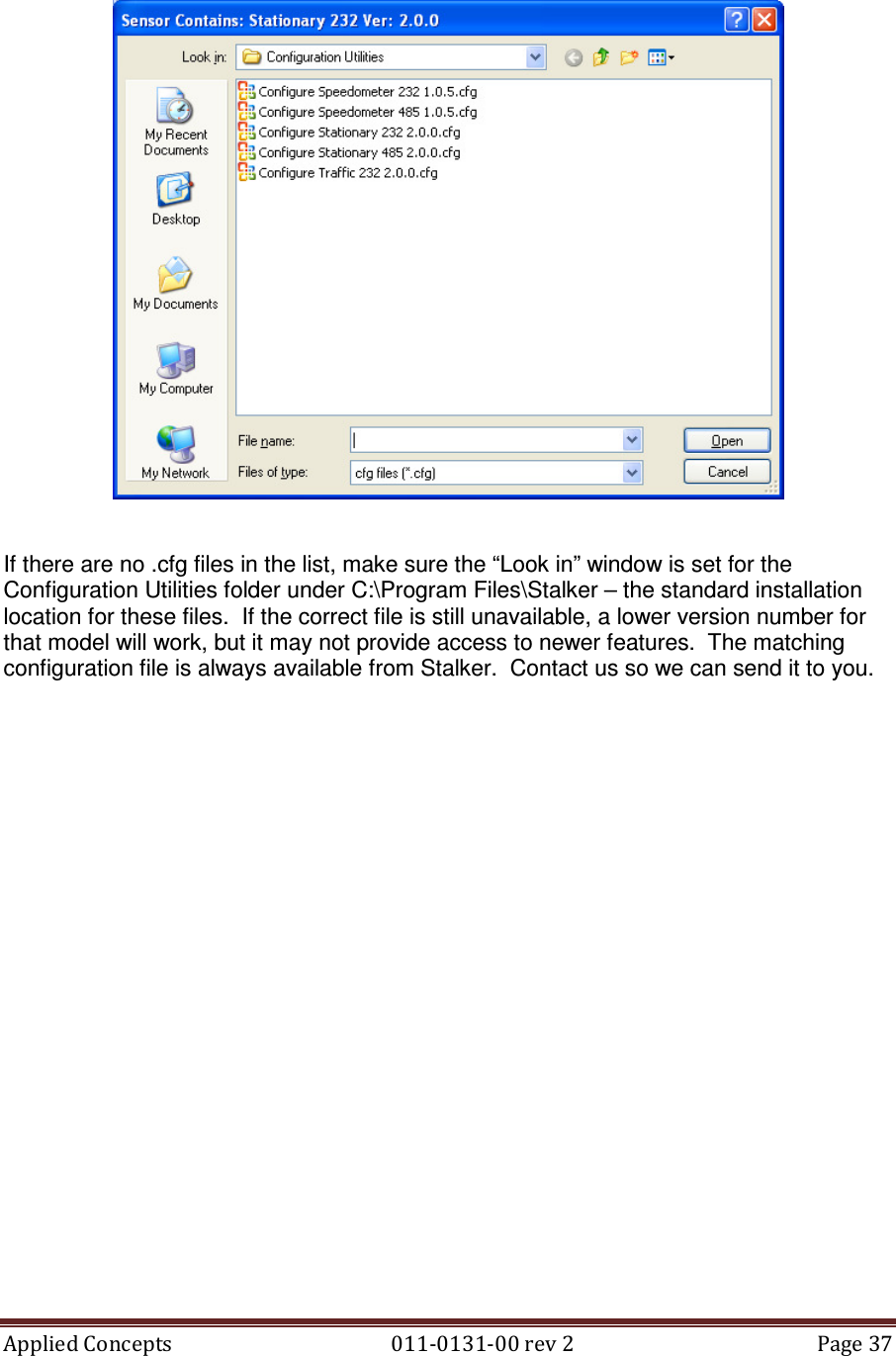
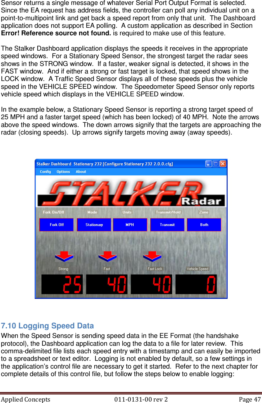
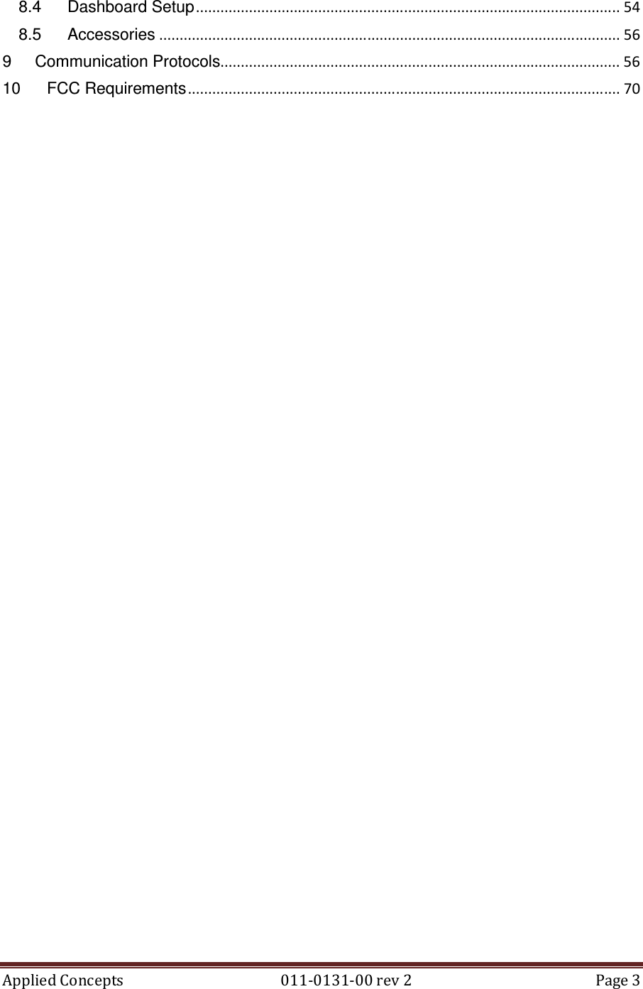
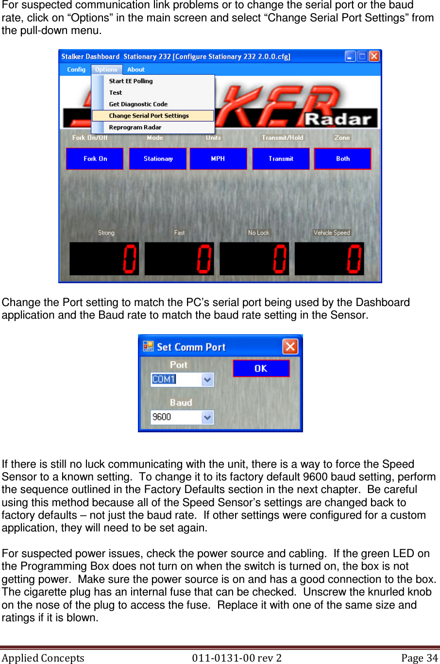
![Applied Concepts 011-0131-00 rev 2 Page 49 Configure Traffic 232 x.x.x.cfg is for a Traffic Speed Sensor version x.x.x. Configure Stationary 232 x.x.x.cfg is for an RS-232 Stationary Speed Sensor. Configure Stationary 485 x.x.x.cfg is for an RS-485 Stationary Speed Sensor. Configure Speedometer 232 x.x.x.cfg is for an RS-232 Speedometer Speed Sensor. Configure Speedometer 485 x.x.x.cfg is for an RS-485 Speedometer Speed Sensor. These files are installed in the C:\Program Files\Stalker\Configuration Utilities folder. Application Control File The control file, Dashboard.ini, is an ASCII text file that may be edited with any text editor such as WordPad or Notepad. It has several control parameters that can be changed to affect the operation of the Speed Sensor application. See a copy of the file below with explanations of the parameters following. [Stalker] PORT=COM1 BAUD=9600 SOURCE_ID=1 DESTINATION_ID=2 CONFIG_FILE=C:\Program Files\Stalker\Configuration Utilities\Configure Stationary 232 2.0.0.cfg CONFIG_FILE_LOCATION=C:\Program Files\Stalker\Configuration Utilities GET_CFG_INTERVAL=5000 RESPONSE_TIMEOUT=500 RETRY=2 EE_FORMAT_INTERVAL=100 ENABLE_SPEED_LOGGING=1 LOG_ALL_SPEED_DATA=0 DATA_LOG_FILE=Speed Log.csv PORT defines the PC serial port used for communication with the Speed Sensor. When the serial port is changed using the Options pull-down “Change Serial Port Settings” function, this parameter in the Dashboard.ini file is automatically changed. It can also be changed by editing the file. After the COM port is changed, the application needs to be closed and re-opened for the newly selected port to be used. BAUD defines the baud rate to be used for communication with the Speed Sensor. As with PORT above, this parameter can also be changed via the Options pull-down “Change Serial Port Settings” function or by editing the file. And after changing the baud rate, the application needs to be closed and re-opened for the setting to take effect. SOURCE_ID is always set to 1 and DESTINATION_ID is always set to 2. When communicating with a Speed Sensor, the application is always the master of the link (ID 1) and the Speed Sensor is always the slave (ID 2). Do not change these values. CONFIG_FILE defines the Speed Sensor configuration file used during a session, and CONFIG_FILE_LOCATION defines the path to that file. These parameters are updated by the application when “Select New Startup Config File” is selected from the Config pull-down menu. The content of configuration files is discussed in detail in the next section.](https://usermanual.wiki/Applied-Concepts/ACMI007/User-Guide-1675608-Page-50.png)
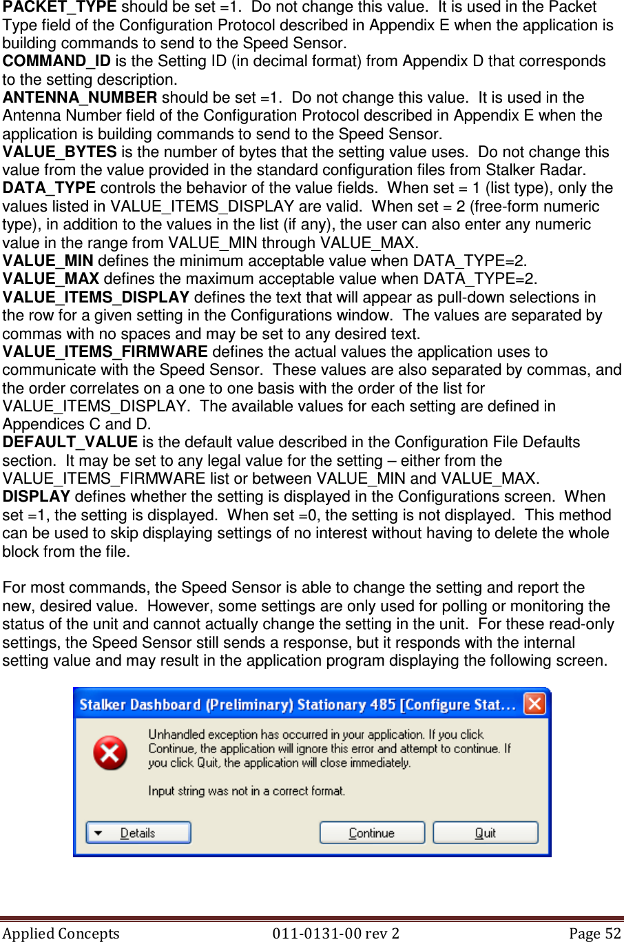
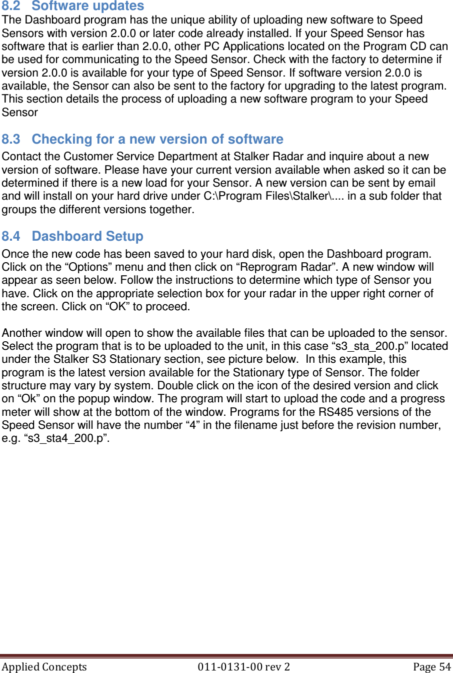
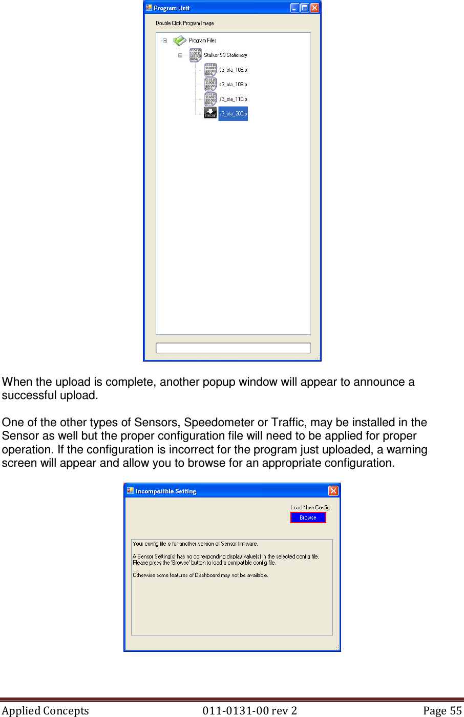
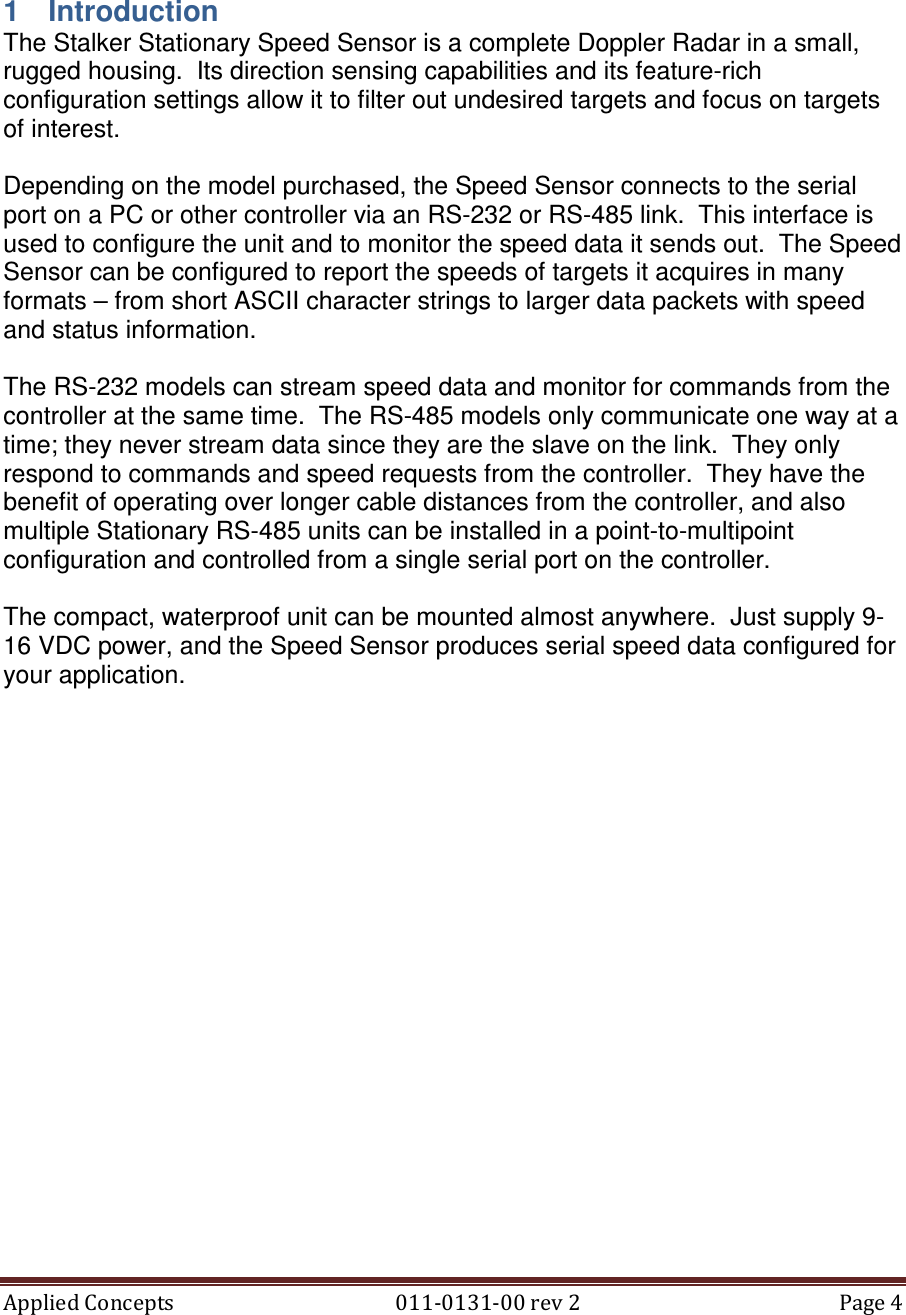
![Applied Concepts 011-0131-00 rev 2 Page 51 The order of the blocks in the .cfg file determines the order in which the settings and their values will be displayed in the Configuration window. As long as the blocks are moved as units, they can be arranged in any order. Blocks for the settings used most often could be placed at the top of the section so their values appear at the top of the Configurations window. Blocks for settings that are never used could even be deleted from the file to speed up the “Edit Firmware Values” process. We recommend copying the standard file provided by Stalker Radar to a file with a new name before making changes. In that way, many custom configuration files can be created for different uses, and the standard file is always available to fall back on for complete control. Each block represents a different configuration setting and has the following format: [Transmitter Control] PACKET_TYPE=1 COMMAND_ID=42 ANTENNA_NUMBER=1 VALUE_BYTES=1 DATA_TYPE=1 VALUE_MIN= VALUE_MAX= VALUE_ITEMS_DISPLAY=Hold,Transmit VALUE_ITEMS_FIRMWARE=0,1 DEFAULT_VALUE=1 DISPLAY=1 The first line in the block defines the name of the setting in brackets. This is the setting description that displays in the left column of the Configurations screen, and it can be changed to any name desired.](https://usermanual.wiki/Applied-Concepts/ACMI007/User-Guide-1675608-Page-52.png)