Applied Wireless Identifications Group DK1025 Dual Frequencies RFID Reader User Manual DK 1025
Applied Wireless Identifications Group Inc. Dual Frequencies RFID Reader Users Manual DK 1025
User Manual
DC-1023 - 1 - 8/5/2010
Your best option for Proximity Access Control
SENTINEL-PROX DK-1025
Dual frequencies RFID Reader
Users Manual-041420

DC-1023 - 2 - 8/5/2010
Your best option for Proximity Access Control
COPYRIGHT ACKNOWLEDGEMENTS
The contents of this document are the property of Applied Wireless Identifications Group, Inc.
(AWID) and are copyrighted. All rights reserved. Any reproduction, in whole or in part, is
strictly prohibited. For additional copies of this document please contact:
AWID
18300 Sutter Blvd
Morgan Hill, CA 95037
http://www.AWID.com
The information contained herein has been carefully checked and is believed to be accurate,
no responsibility is assumed for inaccuracies. AWID reserves the right to make changes
without prior notice. This document is not covered by any warranty either expressed or
implied. Any comments, corrections or additions to the contents of this document should be
directed to AWID at the above address.
Copyright 2010 AWID, Printed in USA.
All other trademarks are the property of their respective owners.
FCC COMPLIANCE
This equipment has been tested and found to be in compliance with the limits for FCC Part 15,
Class B digital device. These limits are designed to provide reasonable protection against
harmful interference when the equipment is operated in a commercial environment. This
equipment generates uses and can radiate radio frequency energy and, if not installed and
used in accordance with instruction manual, may cause harmful interference with radio
communications. Operation of this equipment in a residential area is likely to cause harmful
interference in which case the user will be required to correct the interference at his expense.
The users are prohibited from making any change or modification to this product, any
modification to this product shall void the user’s authority to operate under FCC Part 15
Subpart A Section 15.21 regulations.
“This device complies with Part 15 of the FCC Rules. Operation is subject to the following
two conditions: (1) This device may not cause harmful interference and, (2) this device must
accept any interference received, including interference that may cause undesired
operation.”
INDUSTRY CANADA COMPLIANCE
Operation is subject to the following two conditions: (1) this device may not cause
interference and (2) this device must accept any interference, including interference that
may cause undesired operation of the device.

DC-1023 - 3 - 8/5/2010
Your best option for Proximity Access Control
Table of Contents
REVISION HISTORY .........................................................................................................4
1 INTRODUCTION.........................................................................................................5
1.1 General Descriptions ...........................................................................................5
1.2 Special Features..................................................................................................5
1.3 Suggested Applications .......................................................................................5
2 SPECIFICATIONS......................................................................................................5
2.1 Measuring Read Distance ...................................................................................5
3 PREPARATION FOR INSTALLATION......................................................................6
3.1 Site Survey...........................................................................................................6
3.2 Preferred Reader Installation Practices...............................................................6
3.3 Metal Mounting ....................................................................................................6
3.4 General Wiring Requirements .............................................................................7
3.5 Power Supply.......................................................................................................7
3.6 Grounding ............................................................................................................7
3.7 Wiring Diagrams ..................................................................................................7
4 INSTALLATION PROCEDURE..................................................................................9
4.1 Parts List..............................................................................................................9
4.2 Installation Steps ...............................................................................................10
4.3 Verification .........................................................................................................10
4.4 Mounting ............................................................................................................10
5 WARRANTY .............................................................................................................10
6 RETURN MATERIAL AUTHORIZATION (RMA).....................................................10
7 TROUBLESHOOTING .............................................................................................11
8 PATENTS AND APPROVALS.................................................................................12
NOTE: READ AND USE THIS MANUAL.
NOTE: FAILURE TO FOLLOW THE INSTALLATION GUIDE MAY RESULT IN
POOR PERFORMANCE OR EVEN CAUSE PERMANENT DAMAGE TO THE
READER, THUS VOIDS THE PRODUCT WARRANTY.

DC-1023 - 4 - 8/5/2010
Your best option for Proximity Access Control
REVISION HISTORY
Version
No. Revised
By Date Sections
Affected Remarks
1.0 Z. Wang 7/21/2010 All Initial version
-

DC-1023 - 5 - 8/5/2010
Your best option for Proximity Access Control
1 INTRODUCTION
AWID's Sentinel-Prox DK-1025 Reader is a dual frequencies versatile smart card/smart
label and proximity card reader with 12keys KEYPAD for switch plate mounting. This
Reader will provide simultaneous Wiegand and RS-232 output formats. Its primary
applications are Access Control and Time & Attendance applications.
1.1 GENERAL DESCRIPTIONS
o Thin-line switch plate mounting
o LED visual indicator
o Indoor or outdoor installation
o Audible feedback
1.2 SPECIAL FEATURES
o Simultaneous Wiegand (Access Control) and RS-232 (Time & Attendance)
outputs
o Slim housing designed for single gang box
o Permanently sealed electronics for indoor/outdoor application
o UV stabilized plastic housing
1.3 SUGGESTED APPLICATIONS
o Access Control
o Time & Attendance
o Asset Management
o RFID
2 SPECIFICATIONS
Input voltage .....................+5V to +12 V
Input current .....................150 mA typical
Read range
Smart Card (ISO-14443 A/B) ……………Up to 1.5 inches (3.8 cm)
Smart Labels (ISO-15693)………………..Up to 3 inches (7.6 cm)
Proximity Card (125KHz) ……………….Up to 3 inches(7.6cm)
Transmit frequency .....................13.56 MHz (Pulse command) and 125KHz
Receiver frequency .....................13.56 MHz and 125KHz
Operating temperature range .....................-30° C to +65° C (-22° F to 149° F)
Output format available …….……….Wiegand & RS-232 (Standard)
(Others are available upon request)
Color .....................Dark Gray
2.1 MEASURING READ DISTANCE
To measure the read range between Reader and card, grasp the card by the corner or
near the slot and move the card slowly toward the Reader, with the card surface parallel

DC-1023 - 6 - 8/5/2010
Your best option for Proximity Access Control
to the Reader, until a BEEP occurs. The BEEP indicates that the Reader detects and
read the card. In order to read again, the card must be fully withdrawn from the
Reader’s field of surveillance and then re-approached again. During normal operation,
the card can be presented at any angle relative to the Reader, however this will result in
slight variation of read range.
Note: Do not "wave" the card in front of the Reader. "Waving" the card in front of
the Reader will result in a diminished read range.
3 PREPARATION FOR INSTALLATION
3.1 SITE SURVEY
Always conduct a site survey before starting installation, avoid any possible sources of
interference. If the Reader is not installed properly, the performance will be degraded or
more seriously the Reader may be damaged. The following is a list of installation
procedures that should be followed during installation:
• Do not install the Reader in an area where sources of broadband noise may
exist. Examples of broadband noise sources are motors, pumps, generators,
DC-AC or DA-AC converters, non-interruptible power supplies, AC switching
relays, light dimmers, CRT's, induction heater, ultrasonic welder etc.
• Do not bundle the reader wires together in one conduit with the AC power
cables, lock power, and other signal wiring.
• Keep all the Reader wiring at least 12 inches (30 cm) away from all other
wiring, which includes but not limited to, AC power, computer data wiring,
telephone wiring and wiring to electrical locking devices.
• Do not install the reader within 12 inches (30 cm) of a computer CRT terminal.
3.2 PREFERRED READER INSTALLATION PRACTICES
• Make sure that the supply voltage of the Reader is within specification. As a
rule of thumb, higher supply voltage results in longer read range but at the
expense of higher power consumption.
• Use cables with over-all shield (Screen).
• For best results, run the cable in an individual conduit with at least 12 inches
distance from the AC power, computer data cables and cables for electrical
locking devices.
• Use recommended cable. Do not use any un-shield "Twisted Pair" type cable.
• Use the largest wire gauge possible.
• Use dedicated and linearly regulated power supply, where applicable.
• Use Single Point Grounding (Earthing). No ground loops.
3.3 METAL MOUNTING
The Reader is pre-compensated for mounting on metal utility boxes.
Formatted: Bullets and Numbering

DC-1023 - 7 - 8/5/2010
Your best option for Proximity Access Control
3.4 GENERAL WIRING REQUIREMENTS
All the Reader wiring must be continuously shielded. AWID recommends using #22
AWG up to #18 AWG, six or seven-conductor shielded cables. Longer distances and
higher current consumption on the power supply line will require larger gauge wires.
Refer to Table 1 and Figure 1, Figure 2 and Figure 3 on the following pages to
determine your data lines’ wiring requirement. Due to system data termination
differences, contact your panel manufacturer for their specific requirements.
WIRE SIZE #22 AWG (0.6mm Dia) #18 AWG (1.2mm Dia)
WEIGAND 500ft (152 meters) 980 ft (300 meters)
RS-232 50 ft (15 meters) 50 ft (15 meters)
Table 1 Data Line’s Wiring Requirement
NOTE: WHEN USING AN EXTERNAL POWER SUPPLY, ALWAYS USE A LINEAR
POWER SUPPLY, DO NOT USE A SWITCHING POWER SUPPLY.
3.5 POWER SUPPLY
AVOID using a single power supply for Reader and the magnetic lock. Doing so will
affect the Reader operation and can damage the Reader.
3.6 GROUNDING
Grounding is critical for proper operation of the Reader. When installing the Reader, it is
crucial to assure that the earth ground is the best ground available. If you elect to use
the AC main power ground, conduct a test by measuring its resistance relative to a
known good ground, such as a cold water pipe or a structural steel that is in direct
contact with the ground. This resistance should be less than 50 ohms. If you find that
the AC main power does not provide adequate earth ground, try using a solid
connection to a cold water pipe or for best results drive your own copper clad ground rod
into the earth for the ground point.
For multiple Reader installations, it is critical that all Readers are connected to a single
ground point. Using multiple ground points will create secondary current paths or
ground loops that can affect the performance and cause damage to the Reader.
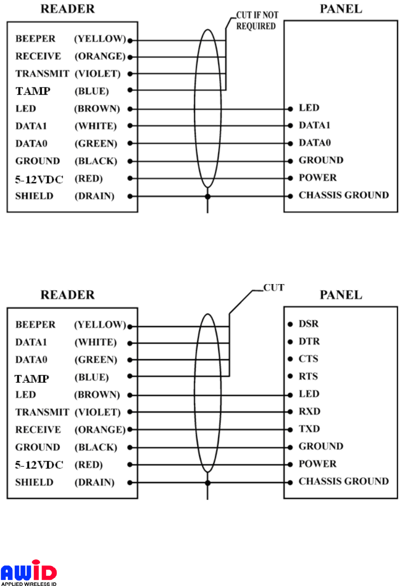
3.7 WIRING DIAGRAMS
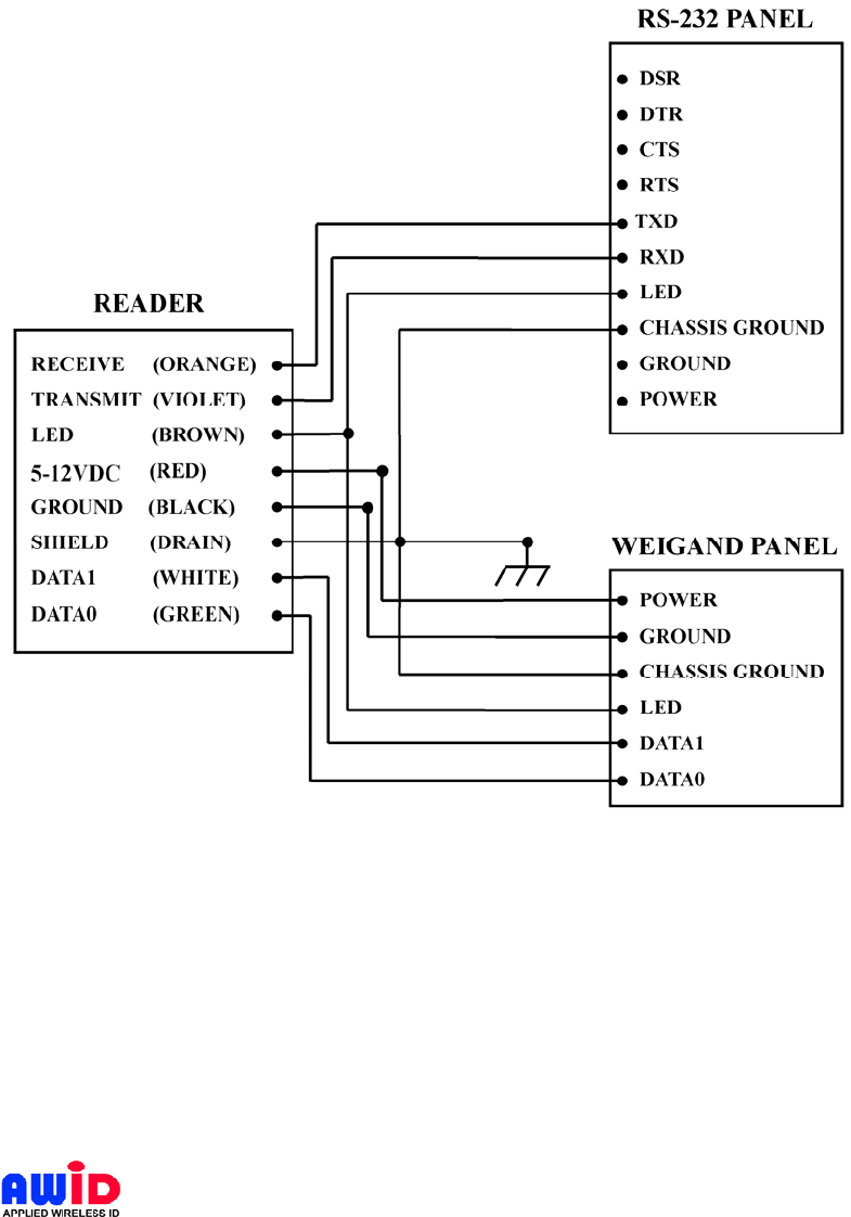
The Reader is designed for Wiegand and RS-232 standard communication formats; use
Figure 1 for Wiegand format installation and Figure 2 for RS-232 format installation, and
use Figure 3 for combined Wiegand and RS-232 installation. If an external power
supply is being used, leave the Panel’s Ground and Power terminals open and connect
the Reader’s Ground (Black) and 5-12VDC (Red) terminals to the external power
supply.
DC-1023 - 8 - 8/5/2010
Your best option for Proximity Access Control
Figure 1 Wiring Diagram for Wiegand Output Format
Figure 2 Wiring Diagram for RS232 Output Format
DC-1023 - 9 - 8/5/2010
Your best option for Proximity Access Control
Figure 3 Wiring Diagram for Wiegand & RS232 Output Format
4 INSTALLATION PROCEDURE
Check to verify that every item listed under Section 5.1 of this manual is present before
starting the installation.
4.1 PARTS LIST
a. Installation sheet, P/N: xxx-xx-x QTY=1
b. Sentinel-Prox DK-1025 Reader, P/N: xxx-xx-x QTY=1
c. #6-32x1” Machine screw P/N: 0616MPP QTY=1

DC-1023 - 10 - 8/5/2010
Your best option for Proximity Access Control
4.2 INSTALLATION STEPS
1. Prepare the single-gang electrical wiring box for Reader mounting. Observe ADA
requirements.
2. If double-gang electrical box is used, drill through the four blind mounting holes on
the four corners of the Reader.
3. Guide the open end of the Panel’s control cable through the access hole on the
electrical junction box. Secure the cable by tightening the cable clamp.
4. Remove the Snap-On cover of the Reader (item b of the parts list)
5. Connect the Reader and the Panel together according to Figure 1 for Wiegand
format, Figure 2 for RS-232 format and Figure 3 for Wiegand/RS-232 format.
6. Setup for the RS-232 is: 9600 baud rate, 1 start bit, 1 stop bit, no parity.
4.3 VERIFICATION
1. Power up the Panel, the LED on the Reader should show RED.
2. Place a “good” card in front of the Reader. The reader will give out “ONE”
audible BEEP and the LED will change from RED to AMBER momentarily and
then flashing between RED & GREEN. The Reader will stay flashing until the
card is removed from the reader. You can repeat this action by placing the
card in front of the reader after the LED turned RED. If the Panel did not right
it must be powered off/on to re initialize.
4.4 MOUNTING
1. Connect the remaining wires to the Panel.
2. Mount the Reader securely to the electrical junction box with #6-32x1
machine screw, (Item c on Parts List.)
3. Install the Snap-On cover.
5 Warranty
AWID’s products are warranted to the original purchaser to be free of defects in material
and workmanship for the life of the product. Any tampering or modification to the
product will void this product warranty. AWID does not warrant any product as to its
merchantability or suitability of use. AWID's sole and complete responsibility under this
warranty is expressly limited to repair or replacement of the warranted product.
6 Return Material Authorization (RMA)
AWID monitors and tracks the life cycle performance of our product through our RMA
system. All customers must obtain a RMA number from AWID Customer Service
Department prior to returning the merchandise. After the customer provides AWID
Customer Service Department with the serial number and a description of the returning
item, a RMA number will be issued. This RMA number must be clearly marked on
the outside of the returned package and noted on the paperwork attached to the
returned merchandise.

DC-1023 - 11 - 8/5/2010
Your best option for Proximity Access Control
When obtaining a RMA number for RFID tags, please provide AWID Customer Service
Department with the serial numbers, card identification numbers, facility codes and etc.
If exact duplicates of returned cards or tags are requested, the customer must provide
AWID with the numbers needed. AWID reserves the option to replace or repair returned
merchandise.
Items returned to AWID without the proper authorization will be returned to the
originators at their own expense.
7 Troubleshooting
This unit, if not installed in strict compliance with AWID’s installation instructions, may
not function to specifications. Use the checklist below to identify the problem:
• Is the card valid and working? - Try some different cards!
• Is the reader wired correctly? - RED-BLK :5-12V, reader should work
• Is the unit grounded properly? - DRAIN-EARTH: less than 50 Ohms
• Is the card presented correctly? - Card face parallel to reader face
• Is a power supply correct? - No switching power supply please!
• Is reader voltage/current correct? - 5-12V @ 150mA typical
• Is the environment free from electromagnetic interference? - Run cable away
from other data carrying cables, reader away from electromagnetic interference
sources!
When troubleshooting, try to identify the source of the problem to a unit level. “Is the
problem originating from the panel?” Or “is the problem originating from the Reader? “
Maybe the problem “is the power supply?”
All AWID’s readers will need only a power supply and a valid card to work properly. If
the reader is only connected with RED (+5-12V) and BLACK (Ground), and presented
with a valid card, the reader will BEEP and momentarily turned AMBER. If the Card
stays within the reader zone of surveillance, the LED on the reader will become flashing
RED and GREEN. When the card is removed, the LED will return to RED, signifying it
has returned to stand-by mode. When the reader works according to the tests above,
the reader is working properly.
Do not cycle the power supply ON and OFF in rapid succession. Each power has its
unique “decay” characteristics, turning the power supply ON and OFF in rapid
succession can cause the Microcontroller to lock-up, due to improper initialization.
Always turn the power supply OFF and count 10 seconds before turning ON again.
To check the validity of the output data in the absence of a panel, you will need to build
a patch cable between the reader and a PC. Call AWID’s Technical Support for details.
If problem persists, consult the system manufacturer. If problem is the reader, consult
AWID’s Technical Assistance Department.

DC-1023 - 12 - 8/5/2010
Your best option for Proximity Access Control
For additional information, please visit AWID’s Web site www.awid.com. For technical
support questions, visit www.awid.com/support, or call +1-408-825-1100 from 8:00 a.m.
to 5:00 p.m. Pacific Time (GMT - 8 hrs).
8 Patents and Approvals
AWID products are covered by United States patent #5594384.
AWID logo is a registered trademark of Applied Wireless Identifications Group, Inc.
Where required, AWID’s products are approved by the appropriate regulatory agencies:
U. S. Federal Communications Commission: Part 15
Underwriter Laboratory:
Designed to Comply with: CE, UL, VDE, BZT, DTI & PTT