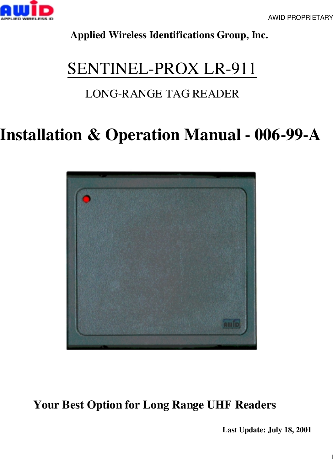
Applied Wireless Identifications Group LR911 Long Range Proximity Reader User Manual

Applied Wireless Identifications Group Inc. Long Range Proximity Reader

User Manual

1     AWID PROPRIETARYApplied Wireless Identifications Group, Inc.SENTINEL-PROX LR-911LONG-RANGE TAG READERInstallation & Operation Manual - 006-99-AYour Best Option for Long Range UHF Readers       Last Update: July 18, 2001
2     AWID PROPRIETARYTable of Contents1.0  Introduction………………………………………………………………………Page  31.1 General Description..…………………………………………………………..   31.2  Special Features…………………………………………………………….…    31.3  Suggested Applications………………..………………………….………….   32.0  Principal of Operation…………………………………………………………………   33.0  Specifications………………………………………………………………………….   43.1  Measuring Read Distance…..……………..……….……………….……….   44.0  Preparation for Installation………….…………………………...…………………...  44.1  Site Survey…………………………………………………………………….  44.2  Preferred Reader Installation Practice………………………………………  54.3  Metal Mounting…………………………….………………………………….  54.4  General Wiring Requirements…………………..……...…………………...  54.5  Power Supply…………………………………………….……………………  64.6  Power Supply Current Draw and Wiring Gauge ………………………….  64.7  Grounding……………………………………………………………………..  74.8  Wiring Diagrams……………………………………………………………...  85.0  Installation Procedure……………………….……………………….……………...  85.1  Parts List………………………………………………………………………  85.2  Installation Steps………………………………..……………………………  85.3  Verification…………………………………………….………………………  85.4  Mounting……………………………………………………………………...          115.5 FCC RF Exposure compliance……………………………………………..           116.0  Warranty…………………….……………………………………………….………..         117.0  Return Material Authorization (RMA)……………………………………...…..….           118.0  Troubleshooting……….………………………………………………….……….…...       119.0  Patents and Approvals…………………………………………………….………....        12NOTE:  READ AND USE THIS MANUAL.FAILURE TO DO SO MAY RESULT IN POOR READER PERFORMANCE OR EVENPERMANENT DAMAGE TO READER, WHICH COULD VOID THE READERWARRANTY.List of TablesTable 4.4-1: Data Line’s Wiring Distance Requirement…………………………….Page  5List of FiguresFigure 4.6-1: Fig. 4.6-1 Read Range VS. Wire Gauge and Supply Voltage (300 ft) Page  6Figure 4.6-2: Fig. 4.6-1 Read Range VS. Wire Gauge and Supply Voltage (500 ft) …….  7Figure 5.2-1: Wiring Diagram for Wiegand Output Format……….…………….……………  9Figure 5.2-2: Wiring Diagram for RS232 Output Format…………………………………….10Figure 5.2-3: Wiring Diagram for RS232 & Wiegand Output Format…….…………………1
3     AWID PROPRIETARY1.0 INTRODUCTION:AWID's Sentinel-Prox LR-911 Reader is a long-range (9 to 11 feet) reader that works withpaper-thin passive windshield mounting tags or credit card size tags. This reader comes with aunique combination of long read range, small size and low power consumption.  LR-911 has aninternal power DC/DC converter, allowing it to work with wide range of supply inputs withoutaffecting its performance. With a 16 V DC supply, its current consumption is less than 400 mA,making it possible to be powered directly from the supply in the access control panel, therebyeliminating the need for an external supply. LR-911 has simultaneous Wiegand and RS-232outputs, its primary applications are automated parking garage entrance control, hands-freeaccess control, asset tracking and asset management applications.1.1  General Descriptions:•  Wall mount or post mount reader•  Indoor or outdoor installation1.2 Special Features:•  Thin passive tags with long range performance•  Designed for automated operation with tags mounted on automobile’s windshield•  Simultaneous Wiegand (Access Control) and RS-232 (transaction control) outputs•  Permanently sealed electronics for indoor or outdoor applications•  UV stabilized plastic housing1.3 Suggested Applications•  Garage Gate Control• Asset Management• Item Tracking• RFID2.0 PRINCIPAL OF OPERATIONThis Radio Frequency Identification (RFID) reader uses radio frequency to identify, locate andtrack people and objects that carry the appropriate transponders.  RFID readers can work innone line-of-sight situations and in darkness, bright sun light or through dirt, grime andsmudges.A typical RFID system consists of three components – an interrogator or reader, a transponderor card and a data processing panel and/or computer combination.  Most RFID readers have aninternal micro-controller, transmitter, receiver and a shared transmit/receive antenna.  The cardis usually passive (no internal battery) and consists of an antenna and RFID ASIC (ApplicationSpecific Integrated Circuit).  During operation, the transmitter sends out an electromagneticwave to establish a zone of surveillance.  When a transponder enters this zone, theelectromagnetic energy from the reader begins to energize the IC in the
4     AWID PROPRIETARYtransponder.  Once the IC is energized, it goes through an initialization process and is ready toaccept further commands. Upon receiving a command to broadcast its identity, the RFID ASICbegins to broadcast its identity through a low energy back-scattering technology that selectivelyreflects or backscatters the electromagnetic energy back to the reader.  The receiving circuits inthe reader senses and decodes this back-scattered signal and hence determines the identity ofthe transponder. 3.0 SPECIFICATIONS-  Input voltage…………………………….   +6V to + 16V DC-  Input current……………………………... 1.2 to 0.40 A typical- Read range:Nominal (Line of Sight) 10 feetTransmit frequency……………………… 902-928 MHz- Receiver frequency……………………… 902-928 MHz  (Amplitude Modulated)-  Operating temperature range…………...-30° C to +55° C-  Color………………………………………. Dark Gray and Beige-  Output formats available……………….. Simultaneous Wiegand & RS-232 (Standard)    (Others are available upon request)3.1 Measuring Read DistanceThe transponder for this Reader is designed for windshield mounting. To measure the readrange between the Reader and the transponder, the transponder must be placed behind a pieceof glass of about 0.25 inches in thickness and the transponder must be flat against the glass.Grasp the transponder by the edges and hold the transponder in the same orientation asindicated in the transponder. Move the transponder toward the Reader, with the card surfaceparallel to the Reader, until confirmed data detection occurs.  This indicates that the Reader hassuccessfully read the transponder.  In order to read again, the card must be fully withdrawn fromthe Reader’s field of view and then approached again.NOTE: FAILURE TO FOLLOW THE INSTALLATION GUIDE MAY RESULT IN POORPERFORMANCE OR EVEN CAUSE PERMANENT DAMAGE TO THE READER,THUS VOIDS THE PRODUCT WARRANTY.4.0  PREPARATION FOR INSTALLATION4.1 Site Survey:Always conduct a site survey before starting installation, avoid any possible sources ofinterference.  If the Reader is not installed properly, the performance will be degraded or moreseriously the Reader may be damaged.  The following is a list of installation procedures thatshould be followed during installation:     AWID PROPRIETARY
5•  Do not install the Reader in an area where sources of broadband electromagnetic noisemay exist. Avoid mounting the reader facing a cellular phone tower or in close proximityto the base station of a 900 MHz wireless telephone.•  Keep all the Reader wiring at least 12 inches (30 cm) away from all other wiring, whichincludes but is not limited to, AC power, computer data wiring, telephone wiring andwiring to electrical locking devices.•  Do not operate the reader in close proximity to any 900 MHz wireless equipments.4.2 Preferred Reader Installation Practices•  Avoid mounting reader under direct sun light.  Sun light in some locations may cause thereader to be operating at temperatures well above the 55 degrees Celsius limit.•  Make sure that the supply voltage of the Reader is within specification.•  Use cables with over-all braid or shield.•  For best results, run the cable in an individual conduit, at least 12 inches from AC power,computer data cables and cables for electrical locking devices.•  Use recommended cable.  Do not use any un-shielded "Twisted Pair" type cable.•  Use the largest wire gauge possible (22AWG and thicker).•  Use a dedicated power supply, where necessary.•  Use Single Point Grounding (Earthing) for black wire of cable. No ground loops. Outershield of cable should not be grounded.4.3 Mounting PreferenceThe LR-911 has a unidirectional antenna with an antenna beam width of about 60-70 degrees.The radiation pattern is a cone shaped beam, which should be aimed to the location where thetransponders will pass. For best results, the antenna should be mounted on a post; about 6 to 7feet from pavement with the antenna angled slightly downward.With a vehicle passing through the drive lane, the center of the antenna radiation pattern shouldproject to the windshield directly in front of the passenger side.Be sure to elevate the antenna slightly to accommodate sport utility vehicles and minivans. Fig.4.3-1 is a typical mounting arrangement that should work in most single lane and multi-lanecases.4.4 General Wiring RequirementsAll the Reader wiring must be continuously shielded.  AWID recommends using #22 AWG up to#18 AWG, six or seven-conductor shielded cables.  Longer distances and higher currentconsumption on the power supply line may require larger gauge wires. Due to system datatermination differences, contact your panel manufacturer for the proper wire sizes to meet theirspecific requirements.     AWID PROPRIETARY
6TABLE 4.4-1: Data Line’s Wiring RequirementWIRE SIZE #22 AWG (0.6mm Dia.) #18 AWG (1.2mm Dia.)WIEGAND 500 ft (152 meters) 980 ft (300 meters)RS-232 45 ft (15 meters) 45 ft (15 meters)4.5 Power SupplyFor consistent performance, choose a Low Noise/High Efficiency switching power supply4.7 GroundingGrounding is critical for proper operation of the Reader.  When installing the Reader, it is crucialto assure that the earth ground is the best ground available.  If you elect to use the AC mainpower ground, conduct a test by measuring its resistance relative to a known good ground, suchas a cold water pipe or a structural steel that is in direct contact with the ground.  The resistanceshould be less than 50 ohms.  If you find that the AC main power does not provide adequateearth ground, try using a solid connection to a cold water pipe.Outer shield of cable should not be grounded.For multiple Reader installations, it is critical that all Readers are connected to the samegrounding system.  Using different grounding systems will create secondary current paths orground loops that can affect the performance and cause damage to the Reader.4.8 Wiring DiagramsSee Fig’s 5.2-1,2,35.0  INSTALLATION PROCEDUREVerify that all item listed in Section 5.1 of this manual are present before starting the installation.5.1  Parts ListA.  Installation sheet, P/N: 006-99-A QTY=1B. Sentinel-Prox LR-911 Reader, P/N: 004-20-A QTY=1C. #6-32 x 1” Machine screw, P/N: 0616MPP  QTY=4D. #6-32 Hex Machine Screw Nuts, P/N: 06NH QTY=5 (1 spare)E. #6 External Tooth Lockwashers, P/N: 06WE QTY=5 (1 spare)F.  Screw hole plug, P/N: 004-27-A QTY=5 (1 spare)     AWID PROPRIETARY5.2  Installation Steps
7Installation Procedure1.)  Position the Reader (Item b on Parts List) at the desired mounting position on amounting post or a mounting surface.  Use Figure. 1 as guide. For straight mounting,drill four small holes for mounting screws, and one clearance hole for reader cable.The installer determines the size of the mounting holes and the clearance hole.2.)  For straight mounting, insert both cable slot plugs (item g on Parts List) to bottomcover.3.)  For side mounting, bend and press the cable into the curved channel and guide thecable out on the desired side of the LR-911. Insert one cable slot plug to the otherside of the bottom cover with no cable coming out.4.)  For Wiegand output, connect the Reader and the Panel together according to Figure2. Install reader onto the mounting surface with items c, d, and e on Parts List. (Forother data format, see Note 3.)5.)  Read Note 1 and below then insert item f. on Parts List into the four screw clearanceholes to conceal the screws.5.3   Verificationa.  Power up the PANEL, Connect a PC, which has the special test program installed, at theRS-232 output port.b.  Place a “good” card in front of the Reader and keep it in that position.  The readerprogram will confirm that the data has been detected. c.  The reader uses an internal micro-controller to manage its many functions, and themicro-controller must be initialized properly.  When the reader show evidence ofmalfunctioning, turn off the reader and wait for ten seconds before energize the readeragain.           AWID PROPRIETARY
8      AWID PROPRIETARYExt Data  (Yellow)Data1 (White)Data0 (Green)RS Ground (Blue)Reset (Brown)Transmit (Violet)Receive (Orange)Ground (Black)6-16 VDC (Red)Shield Drain)Data1DataoGroundPowerChassis GroundFig 5.2.1 Wiring Diagram For Wiegand Output FormatREADER PANELEarthGroundBraid
9     AWID PROPRIETARYExt Data  (Yellow)Data1 (White)Data0 (Green)RS Ground (Blue)Reset (Brown)Transmit (Violet)Receive (Orange)Ground (Black)6-16 VDC (Red)Shield Drain)RS GroundDSRDTRCTSRTSRXDTXDGroundPowerChassis GroundFig 5.2.2 Wiring Diagram For RS-232 Output FormatREADER PANELEarthGroundBraid
10    AWID PROPRIETARYExt Data  (Yellow)Data1 (White)Data0 (Green)RS Ground (Blue)Reset (Brown)Transmit (Violet)Receive (Orange)Ground (Black)6-16 VDC (Red)Shield Drain)RS GroundDSRDTRCTSRTSRXDTXDGroundPowerChassis GroundFig 5.2.3 Wiring Diagram For RS-232 & Wiegand Output FormatREADERRS-232 PANELData1DataoGroundPowerChassis GroundWiegand PANELEarthGroundEarthGroundBraid
115.4  Mountinga.  Check to ensure all connections are secure.  Feed all wires through the cable accesshole to the rear or the side of the mounting position.b.  Mount the Reader with the four #6-32 x 1” Machine screws, P/N: 0616MPP and the four#6-32 Hex Machine Screw Nuts, P/N: 06NH (Item c and d on Parts List).c.  Insert the Screw hole plugs (Item d on Parts List) into the screw clearance holes toconceal the screws. Note: screw hole plugs are designed for one-time use only!Once the plugs are seated, they cannot be removed without damaging the plugs.     AWID PROPRIETARY5.5 FCC RF Exposure complianceCaution: to meet FCC RF Exposure compliance, operator(s) shouldnot be closer than 10.27  inches to a transmitting antenna. Antennas must be labeled indicating minimum separationdistance per FCC RF Exposure requirements . If theinformation on the label is not clearly visible, a sign with the sameinformation must be posted within 36 inches of the antenna.Radio Frequency (RF) exposureIn order for this device to comply with FCC-adopted RF exposure limits, precautions must betaken. To meet the requirements of the FCC’s Maximum Permissible Exposure (MPE)guidelines, persons should not be closer than 10.27 inches (26.1 cm) to a transmitting antenna.For installations where an operator must handle a tag or diagnostic tool closer than 9.88 inchesto the transmitting antenna, the operator should ensure that the RF antenna is not transmittingprior to positioning the tag or tool. Once the operator has positioned the tag or diagnostic tool,and moved away a minimum of 10.27 inches from the antenna, the antenna can be re-activated.For all installations labels must be placed on individual antennas, or signs must be displayed,indicating “CAUTION: A minimum separation distance of 10.27 inches must be maintainedbetween an antenna and persons for meeting FCC RF Exposure compliance. See Usersmanual for details on operation requirements.” For more information on RF Exposure, whereincidental exposure may exceed the above guideline, please refer to the FCC Office ofEngineering and Technology Bulletin 65, Supplement C, Guidelines for Human Exposure toRadio Frequency Electromagnetic Fields, available online at:http://www.fcc.gov/oet/info/documents/bulletins/     AWID PROPRIETARY6.0 WARRANTY
12AWID’s products are warranted to the original purchaser to be free of defects in material andworkmanship for the life of the product.  Any tampering or modification to the product will voidthis product warranty.  AWID does not warrant any product as to its merchantability or suitabilityof use.  AWID's sole and complete responsibility under this warranty is expressly limited torepair or replacement of the warranted product.7.0 RETURN MATERIAL AUTHORIZATION (RMA)AWID monitors and tracks the life cycle performance of our product through our RMA system.All customers must obtain a RMA number from AWID Customer Service Department prior toreturning the merchandise.  After the customer provides AWID Customer Service Departmentwith the serial number and a description of the returning item, a RMA number will be issued.This RMA number must be clearly marked on the outside of the returned package andnoted on the paperwork attached to the returned merchandise.When obtaining a RMA number for RFID tags, please provide AWID’s Customer ServiceDepartment with the serial numbers, card identification numbers, facility codes, etc.  If exactduplicates of returned cards or tags are requested, the customer must provide AWID with thenumbers needed.  AWID reserves the option to replace or repair returned merchandise. Itemsreturned to AWID without the proper authorization will be returned to the originators at their ownexpense.8.0 TROUBLESHOOTINGThis unit, if not installed in strict compliance with AWID’s installation instructions, may notfunction to specifications.  Use the checklist below to identify the problem:•  Is the tag valid and working? - Try a different tag•  Is the reader wired correctly? - Check All Wiring and Connections•  Is the unit grounded properly? - DRAIN-EARTH: less than 50 Ohms•  Is the card presented correctly? - Card face parallel to reader face•  Is a power supply correct? -  Check voltage at power supply•  Is reader voltage/current correct? - 6V/1.2A…16V/0.4 A typical•  Is the environment free from electromagnetic interference? - Run cable away from otherdata carrying cables and the reader away from electromagnetic interference sources!     AWID PROPRIETARY
13When troubleshooting, try to identify the source of the problem to a unit level.  “Is the problemoriginating from the panel?”  Or  “is the problem originating from the Reader? “  Maybe theproblem “is the power supply?”All AWID’s readers will need only a power supply and a valid card to work properly.  If thereader is connected with RED (+6…16V) and BLACK (Ground), and presented with a valid card,the reader will successfully display valid data at the test computer.To check the validity of the output data in the absence of a panel, you will need to build a patchcable between the reader and a PC. Call AWID’s Technical Support for details.If a problem persists, consult the system manufacturer.  If problem is the reader, consult AWID’sTechnical Assistance Department.  AWID help desk is opened from 8:00 AM to 8:00 PMEastern Standard Time, and can be reached by dialing 1-800-369-5533.9.0 PATENTS AND APPROVALSAWID products are covered by United States patent _________, patent pending.AWID logo is a registered trademark of Applied Wireless Identifications Group, Inc.Where required, AWID’s products are approved by the appropriate regulatory agencies:U. S. Federal Communications Commission:  Part 15Underwriter Laboratory: Designed to meet UL 294Designed to Comply with: CE, UL, VDE, BZT, DTI & PTTInformation To The UserThis device complies with part 15 of the FCC Rules. Operation is subject to the following twoconditions: (1) this device may not cause harmful interference, and (2) this device must acceptany interference received, including interference that may cause undesired operation.

Navigation menu