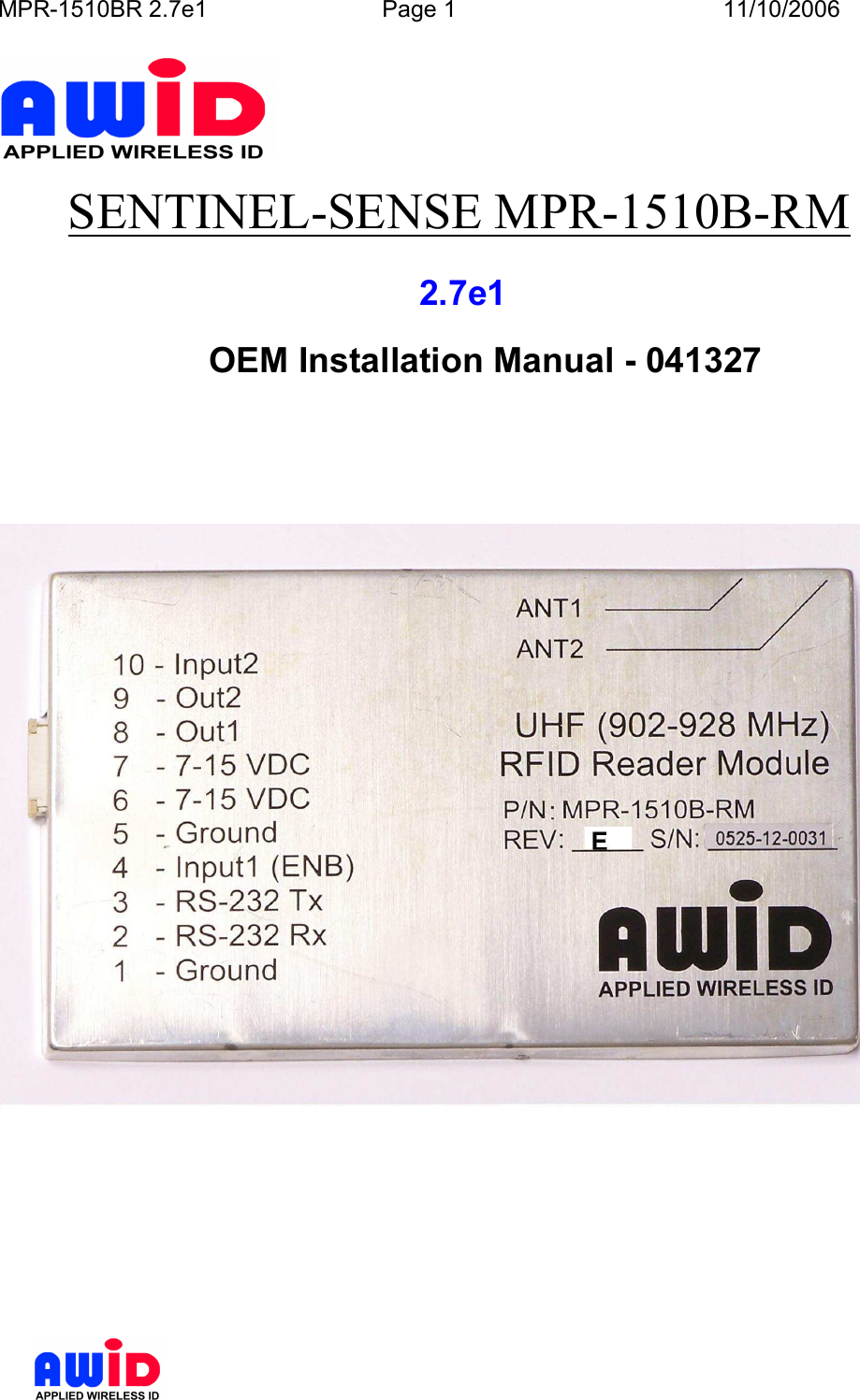
Applied Wireless Identifications Group M27EA UHF RFID reader User Manual 1

Applied Wireless Identifications Group Inc. UHF RFID reader 1

User Manual

MPR-1510BR 2.7e1  Page 1  11/10/2006           SENTINEL-SENSE MPR-1510B-RM              2.7e1       OEM Installation Manual - 041327
MPR-1510BR 2.7e1  Page 2  11/10/2006          COPYRIGHT ACKNOWLEDGEMENTS The contents of this document are the property of Applied Wireless Identifications Group, Inc. (AWID)  and  are  copyrighted.  All  rights  reserved.  Any  reproduction,  in  whole  or  in  part,  is strictly prohibited. For additional copies of this document please contact: AWID 18300 Sutter Blvd Morgan Hill, CA 95037 http://www.AWID.com The information contained herein has been carefully checked and is believed to be accurate, no responsibility is assumed for inaccuracies. AWID reserves the right to make changes without prior notice. This document is not covered by any warranty either expressed or implied. Any comments, corrections or additions to the contents of this document should be directed to AWID at the above address.  Copyright 2006 AWID, Printed in USA. All other trademarks are the property of their respective owners.
MPR-1510BR 2.7e1  Page 3  11/10/2006            SAFETY INFORMATION FOR RF EXPOSURE   IMPORTANT NOTE:  FCC Radiation Exposure Statement:  This equipment complies with FCC radiation exposure limits set forth for an uncontrolled environment. End users must follow the specific operating instructions for satisfying RF exposure compliance.  This device is intended only for OEM integrators under the following conditions:  1.  The antenna must be installed such that 20cm is maintained between the antenna and users;  and  2. The transmitter module may not be co-located with any other transmitter or antenna.  IMPORTANT NOTE: In the event that these conditions can not be met (for example certain laptop configurations or co-location with another transmitter), then the FCC authorization is no longer considered valid and the FCC ID can not be used on the final product. In these circumstances, the OEM integrator will be responsible for re-evaluating the end product (including the transmitter) and obtaining a separate FCC authorization.   End Product Labeling  This transmitter module is authorized only for use in devices where the antenna may be installed such that 20 cm may be maintained between the antenna and users. The final end product must be labeled in visible area with the following: “Contains TX FCC ID: OGSM27EA”   End Product Manual Information  The user manual for end users must include the following information in a prominent location: “IMPORTANT NOTE: To comply with FCC RF exposure compliance requirements, the antenna used for this transmitter must be installed to provide a separation distance of at least 20cm from all persons and must not be co-located or operating in conjunction with any other antenna or transmitter.”
MPR-1510BR 2.7e1  Page 4  11/10/2006           U.S.A.U.S.A.U.S.A.U.S.A.        U.S.FEDERAL COMMUNICATIONS COMMISSION     RADIO FREQUENCY INTERFERENCE STATEMENT  INFORMATION TO THE USER  NOTE : This equipment has been tested and found to comply with the limits for a Class  B digital device pursuant to Part 15 of the FCC Rules.  These limits are designed to provide reasonable protection against harmful Interference in a residential installation This equipment generates, uses, and can radiate radio frequency energy and, if Not installed and used in accordance with the instructions, may cause harmful Interference to radio communications. However, there is no guarantee that interference will not occur in a particular Installation. If this equipment does cause harmful interference to radio or television reception, which can be determined by turning the equipment off and on, the user is encouraged to try to correct the interference by one or more of the following measures:  o  Reorient or relocate the receiving antenna. o  Increase the separation between the equipment and receiver. o  Connect the equipment into an outlet of a circuit different from that to which the receiver is connected. o  Consult the dealer or an experienced radio/TV technician for assistance.  Changes or modification not expressly approved by the party responsible for Compliance could void the user’s authority to operate the equipment. Connecting of peripherals requires the use of grounded shielded signal cables.   FCC Compliance Information  This device complies with Part 15 of FCC Rules. Operation is subject to the following two conditions: 1) This device may not cause harmful interference, and 2) This device must accept any interference received, including interference that may cause undesired operation.
MPR-1510BR 2.7e1  Page 5  11/10/2006          This device has been designed to operate with the antennas listed below, and having a maximum gain of 6 dBi. Antennas not included in this list or having a gain greater than 6 dBi are strictly prohibited for use with this device.  Mfg  Model  Type  Maximum Gain (dBi) AWID  MPR2010ANT  Patch  5.59 AWID  915CPS-A (with 8ft cable AWID PN: RTC8) Patch  4.9 Snyder 1x4 Dipole  Dipole 2.15  To reduce potential radio interference to other users, the antenna type and its gain should be so chosen that the equivalent isotropically radiated power (EIRP) is not more than that required for successful communication.  The OEM integrator will control1 the appropriate power level based on input data as listed in table below:           •                                              1 This refers to a special OEM capability to set the upper limit of the RF Power Level for the device and the operation is password protected. It is not published as one of the protocol commands that are available to end users. Pout (dBm) Code Pout (dBm) Code 30.0  0  20.0  226 29.5  45  19.5  228 29.0  70  19.0  231 28.5  90  18.5  233 28.0  110  18.0  234 27.5  126  17.5  235 27.0  140  17.0  236 26.5  152  16.5  237 26.0  162  16.0  239 25.5  173  15.5  240 25.0  182  14.5  241 24.5  189  14.0  242 24.0  197  12.5  244 23.5  201  11.5  246 23.0  206  10.5  247 22.5  211  10.0  249 22.0  215  7.5  251 21.5  218  7.0  252 21.0  221  6.0  254 20.5  224  5.5  255
MPR-1510BR 2.7e1  Page 6  11/10/2006           Table of Contents 1 INTRODUCTION.................................................................................................................. 7 1.1  Special Features ............................................................................................................... 7 2 SPECIFICATIONS................................................................................................................ 8 2.1  Channel Frequency Table ................................................................................................ 8 2.2  Connector Pin Assignment .............................................................................................. 8 2.3  Measuring Read Distance ................................................................................................ 9 3 INSTALLATION & OPERATION GUIDELINES ......................................................... 10 3.1  Site Survey ..................................................................................................................... 10 3.2  General Wiring Requirements ....................................................................................... 10 3.3  Wiring Diagrams............................................................................................................ 10 4 INSTALLATION PROCEDURE....................................................................................... 11 4.1  Parts List ........................................................................................................................ 11 4.2  Preparation for Installation ............................................................................................ 11 4.2.1 Bench Top Verification .......................................................................................... 11 5 SOFTWARE PROGRAMMING AND SYSTEM OPERATION NOTES .................... 12 5.1  System Operation........................................................................................................... 12 5.1.1 Running a Custom Software Application or the AWID Demo Program ............... 12 5.1.2 Operating Modes ................................................................................................... 12 5.2  Users Note...................................................................................................................... 12 6 MPR SERIAL COMMUNICATION PROTOCOL......................................................... 13  NOTE:  READ AND USE THIS MANUAL.    NOTE: FAILURE TO FOLLOW THE INSTALLATION GUIDE MAY RESULT IN POOR PERFORMANCE OR EVEN CAUSE PERMANENT DAMAGE TO THE READER, THUS VOIDS THE PRODUCT WARRANTY.
MPR-1510BR 2.7e1  Page 7  11/10/2006          1  INTRODUCTION  AWID's Sentinel-Sense MPR-1510B-RM Rev. 2.7e1 (MPR-1510BR 2.7e or simply 2.7e) is  a  long-range  (12  to  15  feet)  Radio  Frequency  IDentification  (RFID)  Reader  Module with RS-232 I/O interface that works with most leading passive UHF passive tags. This reader comes with a unique combination of long read range, small size, and low power consumption.  The  reader  module  has  an  internal  power  converter,  allowing  it  to  work with  a  wide  range  of  supply  inputs  without  affecting  its  performance.  Its  primary applications are asset management and tracking, and fleet management applications.  The MPR-1510BR 2.7e reader modules are delivered with firmware version 2.xxM.  In order to operate an MPR-1510BR 2.7e you will need the following:  PC running Windows2 98 or higher, CD-ROM drive and one RS-232 serial port.  Host software (AWID’s demo software or your own custom software)  1.1  SPECIAL FEATURES  •  Multi-Protocol: ISO-18000-6 Type B (Intellitag, UCODE EPC V1.19 Rev 2), EPC Class 13, Gen 1 & 2, EM •  Thin passive tags with long-range performance •  RS-232 outputs   •                                              2 Though an MPR-1510BR can also be controlled from a non-Windows programming platform, AWID demo and FW upgrade programs are applications to run in Windows. 3 Both 64- and 96-bit
MPR-1510BR 2.7e1  Page 8  11/10/2006          2  SPECIFICATIONS  Input voltage  +7.0 VDC to +15 VDC Input current  1.0 A (7.0 V) to 0.40 A (15 V) typical  Protocol language  ISO Type B (Intellitag, UCODE EPC V1.19 Rev 2),     EPC Class 1 Gen 1 & 2, EM Read range   Depends on type & size of labels used Output power  +30 dBm max Transmit frequency  902.75~927.25 MHz Receiver frequency  902.75~927.25 MHz (Amplitude Modulated) Hopping channels  50 Channels Channel spacing  500 kHz  Hopping sequence  Pseudo random Operating temperature range  -30° C to +65° C (-22° F to 149° F) Output data formats  RS-232 Version: I/O Connector  DB-9 connector  Dimension  3”x5”x0.25”  2.1  CHANNEL FREQUENCY TABLE Frequency range4: 902.75 ~ 927.25 MHz Minimum Number of frequency channels: 50  CH 902~928 MHz CH 902~928 MHz CH 902~928 MHz CH 902~928 MHz CH 902~928 MHz 0 902.75  MHz 10 907.75  MHz 20 912.75  MHz 30 917.75  MHz 40 922.75  MHz 1 903.25  MHz 11 908.25  MHz 21 913.25  MHz 31 918.25  MHz 41 923.25  MHz 2 903.75  MHz 12 908.75  MHz 22 913.75  MHz 32 918.75  MHz 42 923.75  MHz 3 904.25  MHz 13 909.25  MHz 23 914.25  MHz 33 919.25  MHz 43 924.25  MHz 4 904.75  MHz 14 909.75  MHz 24 914.75  MHz 34 919.75  MHz 44 924.75  MHz 5 905.25  MHz 15 910.25  MHz 25 915.25  MHz 35 920.25  MHz 45 925.25  MHz 6 905.75  MHz 16 910.75  MHz 26 915.75  MHz 36 920.75  MHz 46 925.75  MHz 7 906.25  MHz 17 911.25  MHz 27 916.25  MHz 37 921.25  MHz 47 926.25  MHz 8 906.75  MHz 18 911.75  MHz 28 916.75  MHz 38 921.75  MHz 48 926.75  MHz 9 907.25  MHz 19 912.25  MHz 29 917.25  MHz 39 922.25  MHz 49 927.25  MHz   2.2  CONNECTOR PIN ASSIGNMENT  Pin  Function        Pin  Function  1  Ground        6  +7V/+15V 2  RS232 Tx        7  +7V/+15V 3  RS232 Rx        8  Data 0 4  Enable RFID       9  Data 1 5  Ground        10  Ext Data in    •                                              4 Notice that capability to change frequency settings is not available to end users.
MPR-1510BR 2.7e1  Page 9  11/10/2006           2.3  MEASURING READ DISTANCE  Make  sure  you  know  the  tag  types.  For  certain  readers  and  tags,  user  must  also  be mindful  of  the  tag’s  orientation  and  the  reader’s  antenna  orientation,  what  mounting surface the tags are designed for and how the tags are supposed to be mounted. Any departure from its intended purpose will drastically affect the reader’s ability to energize the tag and its read range.  When measuring the reader’s read range, make sure that the tag is properly oriented to the reader antenna, and for optimum performance, be sure the operator’s finger  is  not within three (3) inches of the tag’s antenna surface.
MPR-1510BR 2.7e1  Page 10  11/10/2006          3  INSTALLATION & OPERATION GUIDELINES  For ease of explanation, MPR reader in this section refers to an RFID device that consists of 2.7e and a high performance circular polarized antenna inside a splash proof, UV stabilized housing case.   3.1  SITE SURVEY  3.2  GENERAL WIRING REQUIREMENTS  All the  MPR reader wiring should be continuously shielded.   AWID recommends using #24  AWG  up  to  #22  AWG,  longer  distances  and  higher  current  consumption  on  the power supply line will require larger gauge wires.    TABLE 3.4-1: Data Line’s Wiring Requirement  WIRE SIZE  #22 AWG (0.6 mm Dia.)  #24 AWG (0.5 mm Dia.) RS-232  50 ft (15 meters)  50 ft (15 meters)  3.3  WIRING DIAGRAMS  See section 2.2 for pin assignment for the RS-232 connector of a 2.7e.  The  MPR  RS-232  interface  is  a  short  distance  serial  interface,  a full  command set for the  standard  serial  interface  is  not  necessary,  therefore  only  transmit,  receive  and ground  wires  are  used.  Sense  input  is  an  enable  input,  which  is  traditionally  used  to activate the RF energy of the reader and to start the read functions.
MPR-1510BR 2.7e1  Page 11  11/10/2006          4  INSTALLATION PROCEDURE  This section provides installation and operation information for MPR readers.  4.1  PARTS LIST  Verify that all items listed below are present before starting the installation.  o  Sentinel-Sense MPR-1510BR 2.7e          Qty=1 o  Documentation and Demo Program CD          Qty=1  4.2  PREPARATION FOR INSTALLATION  Familiarize yourself with the connectors and pin out assignment of each I/O connectors. 4.2.1  Bench Top Verification It  is  always  a  good  idea  to  verify  system  operation  before  committing  to  a  full-scale installation.  The  following  are  the  necessary  steps  to  test  the  reader’s  operation  in  a static environment.   Connect MPR reader module to the RS-232 port of a PC  Connect the power jack from the wall plug power supply to reader module  Power up PC  Install demo software on PC  Activate demo software and verify performance of the reader.  Select  a  COM  port  on  top  page  then  click  “Connect”.  Follow  with  some commands.
MPR-1510BR 2.7e1  Page 12  11/10/2006          5  SOFTWARE PROGRAMMING AND SYSTEM OPERATION NOTES  5.1  SYSTEM OPERATION 5.1.1  Running a Custom Software Application or the AWID Demo Program If AWID Demo Program is not used, it is expected user will launch a Custom Software Application developed using the MPR Serial Communication Protocol to send commands as specified to the MPR reader. 5.1.2  Operating Modes Typical operating modes for MPR readers can be grouped into the following modes:  Search Mode  This mode is used when operator or user is not certain what family of tags is placed on the items to be tracked. Since most tags are deterministic in nature, MPR reader must cycle through each and every protocol, issue a protocol specific inquiry, to hail and to wait for a response from tags of that specific protocol. When there are many different protocols in use the reader response will appear sluggish.  Mixed Mode  This mode assumes the user is aware of the types of protocol in use, and furthermore, the user  made  a  determined  effort  to  operate  the  reader  in  a  mixed  protocol  mode.  In  this mode, the user can decide how many and which specific protocols to be selected. Once Mix Protocol Mode is selected, the reader will routinely cycle through each protocol, dwell long enough for the reader to wait for a response and then move on to the next protocol. It should  be  noted  that  in  a  mixed  protocol  mode,  the  tag  must  have  sufficient  time  to respond to the reader, and therefore, it can only be used on a conveyor belt arrangement, with specific speed restrictions.   Single Protocol Mode Single  protocol is  the  normal  mode  of operation,  where the protocol type is known  and many tags are expected to pass through the readers.    5.2  USERS NOTE  For System Integrators and/or Software Developers System Integrators and/or Software developers should get familiar with the MPR Serial Communication  Protocol  specifications  for  developing  applications  that  control  AWID’s Serial Communication MPR readers.  For Custom System Users For  custom  system  user,  please  refer  to  your  host  software  user  guide  for  information regarding system and software operations  For Demo Software Users
MPR-1510BR 2.7e1  Page 13  11/10/2006          If you are using the AWID RFID demonstration software application which is .NET based with easy-to-follow GUI operations, simply select the COM port for which the MPR reader is configured then click “Connect” should get you started.  6  MPR SERIAL COMMUNICATION PROTOCOL  See MPR Serial Communication Protocol Manual - 041304

Navigation menu