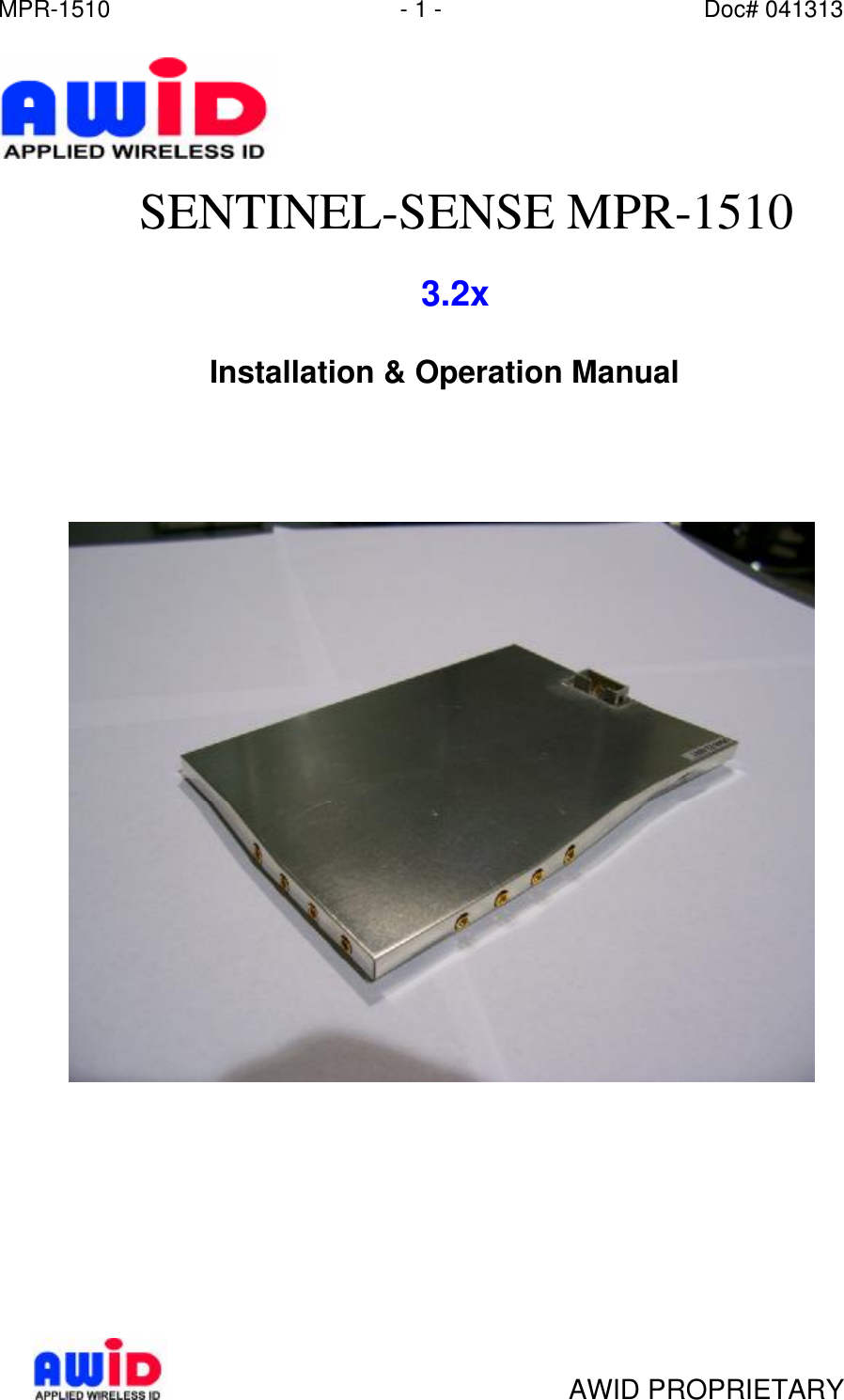
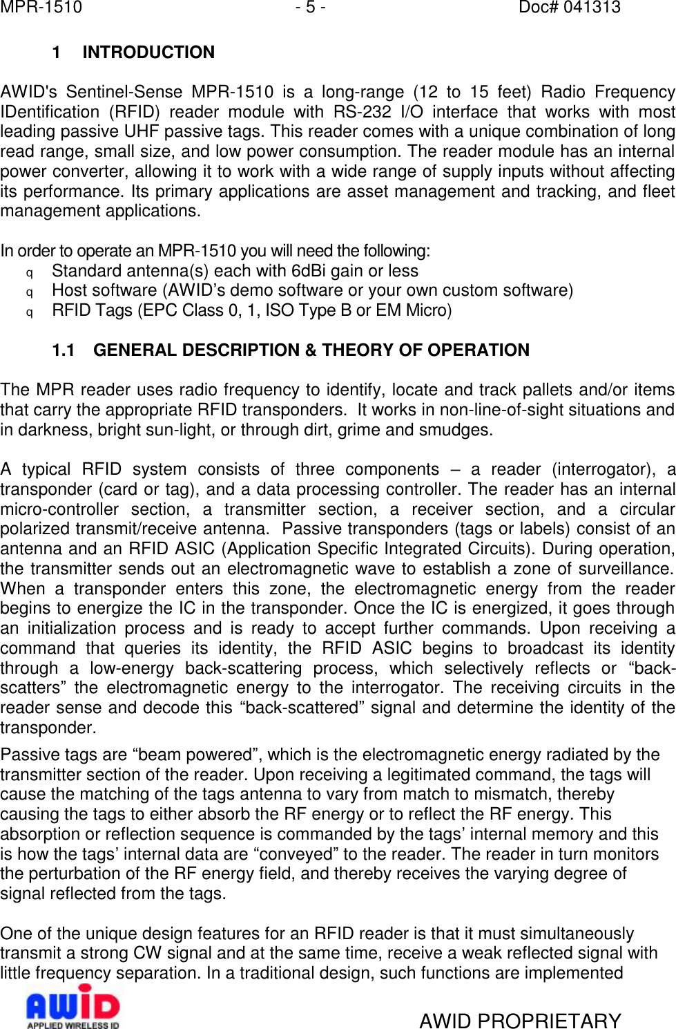
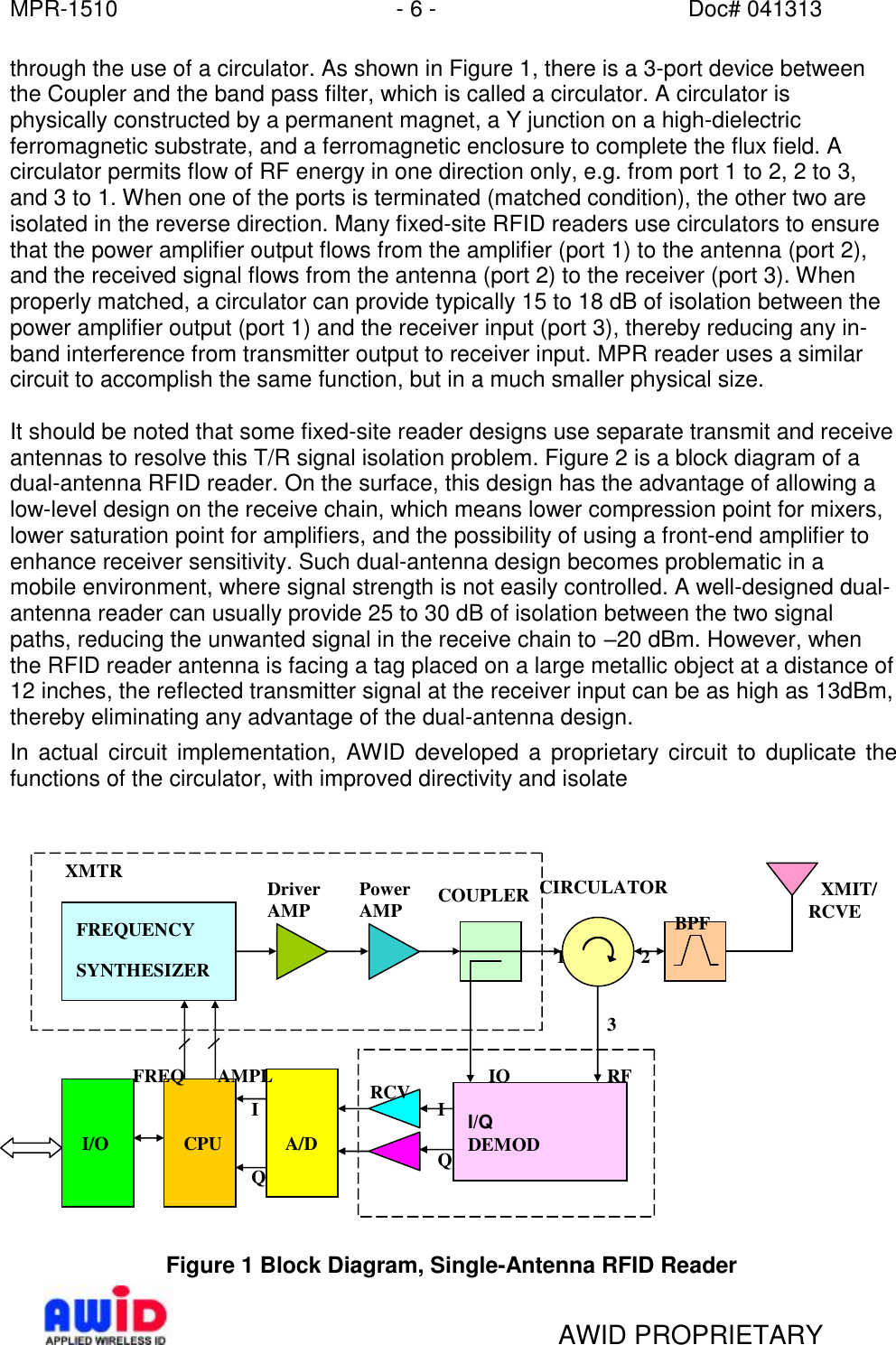
Applied Wireless Identifications Group MPR1510R32 MODULE User Manual Mnul MPR 1510 32x

Applied Wireless Identifications Group Inc. MODULE Mnul MPR 1510 32x

USERS MANUAL

MPR-1510 - 1 - Doc# 041313   AWID PROPRIETARY  SENTINEL-SENSE MPR-1510        3.2x     Installation & Operation Manual
MPR-1510 - 2 - Doc# 041313   AWID PROPRIETARY COPYRIGHT ACKNOWLEDGEMENTS The contents of this document are the property of Applied Wireless Identifications Group, Inc. (AWID) and are copyrighted. All rights reserved. Any reproduction, in whole or in part, is strictly prohibited. For additional copies of this document please contact: AWID 382 Route 59, Section 292 Monsey, NY 10952 www.sales-ast@AWID.com The information contained herein has been carefully checked and is believed to be accurate, no responsibility is assumed for inaccuracies. AWID reserves the right to make changes without prior notice. This document is not covered by any warranty either expressed or implied. Any comments, corrections or additions to the contents of this document should be directed to AWID at the above address.  Copyright 2003 AWID, Printed in USA. All other trademarks are the property of their respective owners.  FCC COMPLIANCE This equipment has been tested and found to be in compliance with the limits for FCC Part 15, Class A digital device. These limits are designed to provide reasonable protection against harmful interference when the equipment is operated in a commercial environment. This equipment generates, uses and can radiate radio frequency energy and, if not installed and used in accordance with instruction manual, may cause harmful interference with radio communications. Operation of this equipment in a residential area is likely to cause harmful interference in which case the user will be required to correct the interference at his own expense.  The users are prohibited from making any change or modification to this product, any modification to this product shall voids the user’s authority to operate under FCC Part 15 Subpart A Section 15.21 regulations.  “This device complies with Part 15 of the FCC Rules. Operation is subject to the following two conditions: (1) This device may not cause harmful interference and, (2) this device must accept any interference received, including interference that may cause undesired operation.”  INDUSTRY CANADA COMPLIANCE Operation is subject to the following two conditions: (1) this device may not cause interference and (2) this device must accept any interference, including interference that may cause undesired operation of the device.
MPR-1510 - 3 - Doc# 041313   AWID PROPRIETARY CAUTION:  Reader should be positioned so that personnel in the area for prolonged periods may safely remain at least 23 cm (9 in) in an uncontrolled environment from the reader’s surface. Observe FCC OET Bulletin 56 “Hazards of radio frequency and electromagnetic fields” and Bulletin 65 “Human exposure to radio frequency electromagnetic fields.”
MPR-1510 - 4 - Doc# 041313   AWID PROPRIETARY  Table of Contents 1 INTRODUCTION......................................................................................................5 1.1 General Description & Theory of Operation......................................................5 1.2 Special Features...............................................................................................7 1.3 Channel Frequency Table.................................................................................7 2 SPECIFICATIONS...................................................................................................8 2.1 Connector Pin Assignment................................................................................8 2.2 Measuring Read Distance.................................................................................8 3 INSTALLATION & OPERATION GUIDELINES......................................................9 3.1 Site Survey........................................................................................................9 3.2 Preferred Reader Installation Practices.............................................................9 3.3 Mounting Preference.........................................................................................9 3.4 General Wiring Requirements.........................................................................10  3.5 Grounding.......................................................................................................10  3.6 Wiring Diagrams..............................................................................................10  4 INSTALLATION PROCEDURE.............................................................................11  4.1 Parts List.........................................................................................................11  4.2 Preparation for Installation..............................................................................11  4.2.1 Bench Top Verification.............................................................................11  4.2.2 Antenna Pattern.......................................................................................11  5 SOFTWARE PROGRAMMING AND SYSTEM OPERATION NOTES..................13 5.1 System Operation............................................................................................13  5.1.1 Running a Custom Software Application or the AWID Demo Program....13 5.1.2 Operating Modes......................................................................................13  5.2 Users Note......................................................................................................13  6 MPR 3014 PROTOCOL.........................................................................................14   NOTE:  READ AND USE THIS MANUAL.  FAILURE TO DO SO MAY RESULT IN POOR READER PERFORMANCE OR EVEN PERMANENT DAMAGE TO READER, WHICH COULD VOID THE READER WARRANTY.    NOTE: FAILURE TO FOLLOW THE INSTALLATION GUIDE MAY RESULT IN POOR PERFORMANCE OR EVEN CAUSE PERMANENT DAMAGE TO THE READER, THUS VOIDS THE PRODUCT WARRANTY.
MPR-1510 - 5 - Doc# 041313   AWID PROPRIETARY 1 INTRODUCTION  AWID's Sentinel-Sense MPR-1510 is a long-range (12 to 15 feet) Radio Frequency IDentification (RFID) reader module with RS-232 I/O interface that works with most leading passive UHF passive tags. This reader comes with a unique combination of long read range, small size, and low power consumption. The reader module has an internal power converter, allowing it to work with a wide range of supply inputs without affecting its performance. Its primary applications are asset management and tracking, and fleet management applications.  In order to operate an MPR-1510 you will need the following: q Standard antenna(s) each with 6dBi gain or less q Host software (AWID’s demo software or your own custom software) q RFID Tags (EPC Class 0, 1, ISO Type B or EM Micro)  1.1 GENERAL DESCRIPTION & THEORY OF OPERATION  The MPR reader uses radio frequency to identify, locate and track pallets and/or items that carry the appropriate RFID transponders.  It works in non-line-of-sight situations and in darkness, bright sun-light, or through dirt, grime and smudges.    A typical RFID system consists of three components  – a reader (interrogator), a transponder (card or tag), and a data processing controller. The reader has an internal micro-controller section, a transmitter section, a receiver section, and a circular polarized transmit/receive antenna.  Passive transponders (tags or labels) consist of an antenna and an RFID ASIC (Application Specific Integrated Circuits). During operation, the transmitter sends out an electromagnetic wave to establish a zone of surveillance.  When a transponder enters this zone, the electromagnetic energy from the reader begins to energize the IC in the transponder. Once the IC is energized, it goes through an initialization process and is ready to accept further commands. Upon receiving a command that queries its identity, the RFID ASIC begins to broadcast its identity through a low-energy back-scattering process, which selectively reflects or  “back-scatters” the electromagnetic energy to the interrogator. The receiving circuits in the reader sense and decode this “back-scattered” signal and determine the identity of the transponder. Passive tags are “beam powered”, which is the electromagnetic energy radiated by the transmitter section of the reader. Upon receiving a legitimated command, the tags will cause the matching of the tags antenna to vary from match to mismatch, thereby causing the tags to either absorb the RF energy or to reflect the RF energy. This absorption or reflection sequence is commanded by the tags’ internal memory and this is how the tags’ internal data are “conveyed” to the reader. The reader in turn monitors the perturbation of the RF energy field, and thereby receives the varying degree of signal reflected from the tags.  One of the unique design features for an RFID reader is that it must simultaneously transmit a strong CW signal and at the same time, receive a weak reflected signal with little frequency separation. In a traditional design, such functions are implemented
MPR-1510 - 6 - Doc# 041313   AWID PROPRIETARY through the use of a circulator. As shown in Figure 1, there is a 3-port device between the Coupler and the band pass filter, which is called a circulator. A circulator is physically constructed by a permanent magnet, a Y junction on a high-dielectric ferromagnetic substrate, and a ferromagnetic enclosure to complete the flux field. A circulator permits flow of RF energy in one direction only, e.g. from port 1 to 2, 2 to 3, and 3 to 1. When one of the ports is terminated (matched condition), the other two are isolated in the reverse direction. Many fixed-site RFID readers use circulators to ensure that the power amplifier output flows from the amplifier (port 1) to the antenna (port 2), and the received signal flows from the antenna (port 2) to the receiver (port 3). When properly matched, a circulator can provide typically 15 to 18 dB of isolation between the power amplifier output (port 1) and the receiver input (port 3), thereby reducing any in-band interference from transmitter output to receiver input. MPR reader uses a similar circuit to accomplish the same function, but in a much smaller physical size.  It should be noted that some fixed-site reader designs use separate transmit and receive antennas to resolve this T/R signal isolation problem. Figure 2 is a block diagram of a dual-antenna RFID reader. On the surface, this design has the advantage of allowing a low-level design on the receive chain, which means lower compression point for mixers, lower saturation point for amplifiers, and the possibility of using a front-end amplifier to enhance receiver sensitivity. Such dual-antenna design becomes problematic in a mobile environment, where signal strength is not easily controlled. A well-designed dual-antenna reader can usually provide 25 to 30 dB of isolation between the two signal paths, reducing the unwanted signal in the receive chain to –20 dBm. However, when the RFID reader antenna is facing a tag placed on a large metallic object at a distance of 12 inches, the reflected transmitter signal at the receiver input can be as high as 13dBm, thereby eliminating any advantage of the dual-antenna design.  In actual circuit implementation, AWID developed a proprietary circuit to duplicate the functions of the circulator, with improved directivity and isolate                       Figure 1 Block Diagram, Single-Antenna RFID Reader FREQUENCY  SYNTHESIZER 1.1.31.1.4 I/Q DEMOD Driver AMP Power AMP COUPLER    XMIT/ RCVE A/DCPU I/O XMTR CIRCULATOR BPF RCV IO RF I Q I Q FREQ AMPL 1 2 3
MPR-1510 - 7 - Doc# 041313   AWID PROPRIETARY                     Figure 2 Block Diagram, Dual-Antenna RFID Reader   1.2 SPECIAL FEATURES  • Multi-Protocol: ISO-18000-6 Type A/B, EPC Class 11, Gen 1 & 2, EM Micro, MH-10, AIAG, EPC Class02 • Thin passive tags with long-range performance • RS-232 outputs   1.3 CHANNEL FREQUENCY TABLE Frequency range: 902 ~ 928 MHz Minimum Number of frequency channels: 50  CH 902~928 MHz CH 902~928 MHz CH 902~928 MHz CH 902~928 MHz CH 902~928 MHz 0 902.50 MHz 10 907.50 MHz 20 912.50 MHz 30 917.50 MHz 40 922.50 MHz 1 903.00 MHz 11 908.00 MHz 21 913.00 MHz 31 918.00 MHz 41 923.00 MHz 2 903.50 MHz 12 908.50 MHz 22 913.50 MHz 32 918.50 MHz 42 923.50 MHz 3 904.00 MHz 13 909.00 MHz 23 914.00 MHz 33 919.00 MHz 43 924.00 MHz 4 904.50 MHz 14 909.50 MHz 24 914.50 MHz 34 919.50 MHz 44 924.50 MHz 5 905.00 MHz 15 910.00 MHz 25 915.00 MHz 35 920.00 MHz 45 925.00 MHz 6 905.50 MHz 16 910.50 MHz 26 915.50 MHz 36 920.50 MHz 46 925.50 MHz 7 906.00 MHz 17 911.00 MHz 27 916.00 MHz 37 921.00 MHz 47 926.00 MHz 8 906.50 MHz 18 911.50 MHz 28 916.50 MHz 38 921.50 MHz 48 926.50 MHz 9 907.00 MHz 19 912.00 MHz 29 917.00 MHz 39 922.00 MHz 49 927.00 MHz   •                                             1 Both 64- and 96-bit 2 Both 64- and 96-bit and Impinj 96-bit 1.1.14.1.1.1   XMIT RF Q Q RCVR FREQUENCY SYNTHESIZER Driver AMP  Power AMP  COUPLER BPF BPF A/D CPU I/O I I/Q DEMOD IQ I OFREQ AMPL XMTR
MPR-1510 - 8 - Doc# 041313   AWID PROPRIETARY 2 SPECIFICATIONS  Input voltage +7.0 VDC to +15 VDC Input current 1.0 A (7.0 V) to 0.40 A (15 V) typical  Protocol language EPC Class 1&0, EM Micro, ISO-18000-6 Type A/B, MH-10, AIAG Read range  Depends on type & size of labels used Output power 1.0 Watt into 6 dBi antenna Transmit frequency 902-928 MHz Receiver frequency 902-928 MHz (Amplitude Modulated) Hopping channels 50 Channels Channel spacing 500 kHz  Hopping sequence Pseudo random Operating temperature range -30° C to +65° C (-22° F to 149° F) Output data formats RS-232 Version: I/O Connector DB-9 connector  Dimension 4”x6”x0.25”  2.1 CONNECTOR PIN ASSIGNMENT  Pin# Function   Pin# Function    1  Data 1    6 Enable RFID 2  Ext Data in   7 Ground 3  RS232 Tx   8 +7V/+15V 4  Data 0    9 Ground 5  RS232 Rx   10 +7V/+15V  2.2 MEASURING READ DISTANCE  Make sure you know the tag types. For certain readers and tags, user must also be mindful of the tag’s orientation and the reader’s antenna orientation, what mounting surface the tags are designed for and how the tags are supposed to be mounted. Any departure from its intended purpose will drastically affect the reader’s ability to energize the tag and its read range.  When measuring the reader’s read range, make sure that the tag is properly oriented to the reader antenna, and for optimum performance, be sure the operator’s finger is not within three (3) inches of the tag’s antenna surface.
MPR-1510 - 9 - Doc# 041313   AWID PROPRIETARY 3 INSTALLATION & OPERATION GUIDELINES  FAILURE TO FOLLOW THESE GUIDELINES MAY RESULT IN POOR PERFORMANCE OR EVEN CAUSE PERMANENT DAMAGE TO THE READER, THUS VOIDS THE PRODUCT WARRANTY.   For ease of explanation, MPR reader in this section refers to an MPR-3014 reader model, i.e., a unit that consists of MPR-1510 (3.2x) inside a splash proof, UV stabilized housing case and high performance circular polarized antenna(s).    3.1 SITE SURVEY Always conduct a site survey before starting installation. Avoid any possible sources of interference.  For best result, use a spectrum analyzer with a wideband antenna and set the spectrum analyzer in Max Hold mode to gain measurement of the maximum signal strength on the airwave. If the MPR reader is not installed properly, the performance will be degraded.  Listed below are steps that should be followed during installation:  • Do not install the MPR reader in an area where sources of broadband noise may exist. Avoid mounting the reader facing a cellular phone tower or in close proximity to the base station of a 900 MHz wireless telephone.   • Keep all of the MPR reader wiring a safe distance from all other wiring, including, but not limited to, AC power, computer data wiring, and telephone wiring, and wiring to electrical locking devices. • Avoid operating the MPR reader in close proximity to other 900 MHz wireless local area networking (WLAN) equipment. It should be noted that MPR-2010s (, etc. are known to work in electromagnetic crowded areas, such as trade shows.  3.2 PREFERRED READER INSTALLATION PRACTICES   • Avoid mounting the MPR reader under direct sunlight.  Exposure to direct sunlight may cause the reader to operate at a temperature above the 65 degrees Celsius upper limit. • Make sure that the supply voltage of the MPR reader is within specification • Use cables with over-all shield (screen) • For best results, avoid bundling data cable with AC power and computer cables • Use the largest wire gauge where feasible • Use dedicated power supply, where necessary • Use Single Point Grounding, and avoid ground loops  3.3 MOUNTING PREFERENCE  An MPR-3014 reader uses uni-directional antennas each with an antenna beam width of about 60-70 degrees.  The radiation pattern is an oval-shaped beam, which should be aimed toward where the transponders will pass.
MPR-1510 - 10 - Doc# 041313   AWID PROPRIETARY 3.4 GENERAL WIRING REQUIREMENTS  All the MPR reader wiring should be continuously shielded.  AWID recommends using #24 AWG up to #22 AWG, longer distances and higher current consumption on the power supply line will require larger gauge wires. PG I/O output are standard access industry Wiegand drivers, which is capable of 500 feet driving distance.    TABLE 3.4-1: Data Line’s Wiring Requirement  WIRE SIZE #22 AWG (0.6 mm Dia.) #24 AWG (0.5 mm Dia.) RS-232 50 ft (15 meters) 50 ft (15 meters)  3.5 GROUNDING  Grounding is critical for proper operation of MPR-1510.  When installing the readers, it is crucial to assure that the earth ground is the best ground available.  If you elect to use the 120 VAC power ground, conduct a test by measuring its resistance relative to a known good ground, such as a cold water pipe or structural steel that is in direct contact with the ground. The resistance should be less than 50 ohms.    3.6 WIRING DIAGRAMS  See section 2.1 for pin assignment for the RS-232 connector of an MPR-1510 3.2x.  The MPR RS-232 interface is a short distance serial interface, a full command set for the standard serial interface is not necessary, therefore only transmit, receive and ground wires are used. Sense input is an enable input, which is traditionally used to activate the RF energy of the reader and to start the read functions.
MPR-1510 - 11 - Doc# 041313   AWID PROPRIETARY 4 Installation Procedure This section provides installation and operation information for MPR readers.  Verify that all items listed below are present before starting the installation. 4.1 PARTS LIST o Sentinel-Sense MPR-1510 reader module 3.2x    Qty=1 o Documentation and Demo Program CD     Qty=1  4.2 PREPARATION FOR INSTALLATION Familiarize yourself with the connectors and pin out assignment of each I/O connectors. 4.2.1 Bench Top Verification It is always a good idea to verify system operation before committing to a full-scale installation. The following are the necessary steps to test the reader’s operation in a static environment.  q Connect MPR reader module to the RS-232 port of a PC q Connect power (via the power jack from a wall plug power supply) to the MPR reader module q Connect Antenna(s) q Power up PC q Install demo software on PC q Activate demo software and verify performance of the reader. q Select COM port 1 on top page then click  “Connect”. Follow with some commands3. q Place the RFID tags at the exact same locations as the final configuration q Measure tag read distance and confirm that read distance is correct.  4.2.2 Antenna Pattern MPR-1510 performs best with a circular polarized antenna to ensure reading tag with random orientation. Most circular polarized antenna has a horizontal to vertical differential of up to 3 dB, this will cause the antenna pattern to deviate from a true circle. AWID’s antenna used in MPR-2010 readers has a horizontal to vertical differential of typically less than 0.5 dB, making its pattern as near to a circle as possible. • Antenna pattern measurements represent both horizontal and vertical polarized planes of the read area transmitted by the reader. • In the drawing below, R = approximately 12 feet to 15 feet with Alien free space tags. • Antenna pattern can be affected by RFI and other environmental conditions. •                                             3 Try a simple command first, e.g., File -> Firmware Version. A good result (v.s. an error message) returned is indication of connection well in place.
MPR-1510 - 12 - Doc# 041313   AWID PROPRIETARY 0.15 00.250.50.75R0Distance (R)Width( W)W (0.72R) Figure 3  Antenna Pattern
MPR-1510 - 13 - Doc# 041313   AWID PROPRIETARY 5 SOFTWARE PROGRAMMING AND SYSTEM OPERATION NOTES  5.1 SYSTEM OPERATION 5.1.1 Running a Custom Software Application or the AWID Demo Program If AWID Demo Program is not used, it is expected user will launch a Custom Software Application developed using the MPR 3014 Protocol to send commands as specified to the MPR reader. 5.1.2 Operating Modes Typical operating modes for MPR readers can be grouped into the following modes:  Search Mode  This mode is used when operator or user is not certain what family of tags are placed on the items to be tracked. Since most tags are deterministic in nature, MPR reader must cycle through each and every protocol, issue a protocol specific inquiry, to hail and to wait for a response from tags of that specific protocol. Therefore, if there are many different protocols, for an untrained observer, the reader response will appear sluggish.  Mixed Mode  This mode assumes the user is aware of the types of protocol in use, and furthermore, the user made a determined effort to operate the reader in a mixed protocol mode. In this mode, the user can decide how many and which specific protocols to be selected. Once Mix Protocol Mode is selected, the reader will routinely cycle through each protocol, dwell long enough for the reader to wait for a response and then move on to the next protocol. It should be noted that in a mixed protocol mode, the tag must have sufficient time to respond to the reader, and therefore, it can only be used on a conveyor belt arrangement, with specific speed restrictions.   Single Protocol Mode Single protocol is the normal mode of operation, where the protocol type is known and many tags are expected to pass through the readers.    5.2 USERS NOTE  For System Integrators and/or Software Developers System Integrators and/or Software developers should get familiar with the MPR 3014 Protocol specifications for developing applications that control AWID’s Serial Communication MPR readers.  For Custom System Users For custom system user, please refer to your host software user guide for information regarding system and software operations  For Demo Software Users
MPR-1510 - 14 - Doc# 041313   AWID PROPRIETARY If you are using the AWID RFID demonstration software application which is .NET based with easy-to-follow GUI operations, simply select the COM port for which the MPR reader is configured then click “Connect” should get you started.  6 MPR 3014 PROTOCOL  See MPR 3014 Protocol Manual - 041310

Navigation menu