Applied Wireless Identifications Group R26H3LR911 RFID Reader User Manual 1
Applied Wireless Identifications Group Inc. RFID Reader 1
User Manual
LR-911 2.6H3
AWID PROPRIETARY
Page 1 9/26/2007
SENTINEL-PROX LR-911 2.6H3
LONG-RANGE TAG READER
Installation & Operation Manual-041359

LR-911 2.6H3
AWID PROPRIETARY
Page 2 9/26/2007
COPYRIGHT ACKNOWLEDGEMENTS
The contents of this document are the property of Applied Wireless Identifications Group, Inc.
(AWID) and are copyrighted. All rights reserved. Any reproduction, in whole or in part, is
strictly prohibited. For additional copies of this document please contact:
AWID
18300 Sutter Blvd
Morgan Hill, CA 95037
http://www.AWID.com
The information contained herein has been carefully checked and is believed to be accurate,
no responsibility is assumed for inaccuracies. AWID reserves the right to make changes
without prior notice. This document is not covered by any warranty either expressed or
implied. Any comments, corrections or additions to the contents of this document should be
directed to AWID at the above address.
Copyright 2006 AWID, Printed in USA.
All other trademarks are the property of their respective owners.
FCC COMPLIANCE
This equipment has been tested and found to be in compliance with the limits for FCC Part 15,
Class A digital device. These limits are designed to provide reasonable protection against
harmful interference when the equipment is operated in a commercial environment. This
equipment generates, uses and can radiate radio frequency energy and, if not installed and
used in accordance with instruction manual, may cause harmful interference with radio
communications. Operation of this equipment in a residential area is likely to cause harmful
interference in which case the user will be required to correct the interference at his own
expense.
The users are prohibited from making any change or modification to this product, any
modification to this product shall voids the user’s authority to operate under FCC Part 15
Subpart A Section 15.21 regulations.
“This device complies with Part 15 of the FCC Rules. Operation is subject to the following
two conditions: (1) This device may not cause harmful interference and, (2) this device must
accept any interference received, including interference that may cause undesired
operation.”
INDUSTRY CANADA C OMPLIANCE
Operation is subject to the following two conditions: (1) this device may not cause
interference and (2) this device must accept any interference, including interference that
may cause undesired operation of the device.

LR-911 2.6H3
AWID PROPRIETARY
Page 3 9/26/2007
C AUTION:
Reader should be positioned so that personnel in the area for prolonged periods may
safely remain at least 20 cm (8 in) in an uncontrolled environment from the reader’s surface.
Observe FCC OET Bulletin 56 “Hazards of radio frequency and electromagnetic fields” and
Bulletin 65 “Human exposure to radio frequency electromagnetic fields.”

LR-911 2.6H3
AWID PROPRIETARY
Page 4 9/26/2007
Table of Contents
REVISION HISTORY .................................................................................................................. 5
1 INTRODUCTION.................................................................................................................. 6
1.1 General Descriptions........................................................................................................ 6
1.2 Special Features ............................................................................................................... 6
1.3 Suggested Applications.................................................................................................... 6
2 SPECIFICATIONS................................................................................................................ 7
2.1 Channel Frequency Hopping Table ................................................................................. 7
2.2 Measuring Read Distance ................................................................................................ 8
3 PREPARATION FOR INSTALLATION ........................................................................... 9
3.1 Site Survey ....................................................................................................................... 9
3.2 Preferred Reader Installation Practices............................................................................ 9
3.3 Mounting Preference........................................................................................................ 9
3.4 General Wiring Requirements ....................................................................................... 10
3.6 Grounding ...................................................................................................................... 10
3.7 Wiring Diagrams............................................................................................................ 10
4 INSTALLATION PROCEDURE....................................................................................... 13
4.1 Parts List ........................................................................................................................ 13
4.2 Installation Steps............................................................................................................ 13
4.3 Verification .................................................................................................................... 13
4.4 Mounting........................................................................................................................ 13
Figure 1 Wiegand Output Format ............................................................................................ 11
Figure 2 RS-232 Output Format............................................................................................... 11
Figure 3 RS-232 & Wiegand Output Format ........................................................................... 12
NOTE: READ AND USE THIS MANUAL.
NOTE: FAILURE TO FOLLOW THE INSTALLATION GUIDE MAY RESULT IN
POOR PERFORMANCE OR EVEN CAUSE PERMANENT DAMAGE TO THE
READER, THUS VOIDS THE PRODUCT WARRANTY.

LR-911 2.6H3
AWID PROPRIETARY
Page 5 9/26/2007
REVISION HISTORY
Version
No.
Revised
By
Date Sections
Affected
Remarks
0.1 E. Wei 9/2007 All Initial version

LR-911 2.6H3
AWID PROPRIETARY
Page 6 9/26/2007
1 INTRODUCTION
AWID's Sentinel-Prox LR-911 2.6H3 is a long-range (9 to 11 feet) Radio Frequency
IDentification (RFID) reader that works with paper-thin passive windshield mouting tags
or credit card size tags. This reader comes with a unique combination of long read
range, small size, and low power consumption. It has an internal power converter,
allowing it to work with a wide range of supply inputs without affecting its performance.
With a 15 V DC supply, its current consumption is less than 500 mA, making it possible
to be powered directly from the supply in the access control panel, thereby eliminating
the need for an external supply. LR-911 has simultaneous Wiegand and RS-232
outputs, its primary applications are automated parking garage entrance control, hands-
free access control, asset tracking and asset management applications.
1.1 GENERAL DESCRIPTIONS
◦ Wall mount or post mount reader ◦ Metal back plate for attachment
◦ Indoor or outdoor installation ◦ Wiegand and RS-232 output
1.2 SPECIAL FEATURES
• Thin passive tags with long-range performance
• Designed for automated operation with tags mounted on automobile’s windshield
• Simultaneous Wiegand (Access Control) and RS-232 (transaction control) outputs
• Permanently sealed electronics for indoor or outdoor applications
• UV stabilized plastic housing
1.3 SUGGESTED APPLICATIONS
◦ Garage Gate Control ◦ Item Tracking
◦ Asset Management ◦ RFID

LR-911 2.6H3
AWID PROPRIETARY
Page 7 9/26/2007
2 SPECIFICATIONS
- Input voltage……………………… ................ +7.0 VDC to +15 VDC
- Input current………………………................. 1.0 A (7.0 V) to 0.50 A (15 V) typical
- Read range:
Prox-Linc WS Windshield Tag……………….Up to 11 feet
Prox-Linc MT Metal Tag………………………Up to 11 feet
- Transmit frequency………………................. 902-928 MHz
- Receiver frequency………………................. 902-928 MHz (Amplitude Modulated)
- Hopping channels………………................... 123 Channels
- Channel spacing…………………. ................ 200 kHz
- Hopping sequence……………….................. Pseudo random
- Operating temperature range……................ -30° C to +65° C (-22° F to 149° F)
- Color……………………………….. ............... Beige
- Output data format……………….................. Simultaneous Wiegand & RS232 (Standard)
2.1 CHANNEL FREQUENCY HOPPING TABLE
CH
902~928
MHz
CH
902~928
MHz
CH
902~928
MHz
CH
902~928
MHz
CH 902~928
MHz
0 902.80 MHz
25 907.80 MHz
50 912.80 MHz
75 917.80 MHz
100
922.80 MHz
1 903.00 MHz
26 908.00 MHz
51 913.00 MHz
76 918.00 MHz
101
923.00 MHz
2 903.20 MHz
27 908.20 MHz
52 913.20 MHz
77 918.20 MHz
102
923.20 MHz
3 903.40 MHz
28 908.40 MHz
53 913.40 MHz
78 918.40 MHz
103
923.40 MHz
4 903.60 MHz
29 908.60 MHz
54 913.60 MHz
79 918.60 MHz
104
923.60 MHz
5 903.80 MHz
30 908.80 MHz
55 913.80 MHz
80 918.80 MHz
105
923.80 MHz
6 904.00 MHz
31 909.00 MHz
56 914.00 MHz
81 919.00 MHz
106
924.00 MHz
7 904.20 MHz
32 909.20 MHz
57 914.20 MHz
82 919.20 MHz
107
924.20 MHz
8 904.40 MHz
33 909.40 MHz
58 914.40 MHz
83 919.40 MHz
108
924.40 MHz
9 904.60 MHz
34 909.60 MHz
59 914.60 MHz
84 919.60 MHz
109
924.60 MHz
10 904.80 MHz
35 909.80 MHz
60 914.80 MHz
85 919.80 MHz
110
924.80 MHz
11 905.00 MHz
36 910.00 MHz
61 915.00 MHz
86 920.00 MHz
111
925.00 MHz
12 905.20 MHz
37 910.20 MHz
62 915.20 MHz
87 920.20 MHz
112
925.20 MHz
13 905.40 MHz
38 910.40 MHz
63 915.40 MHz
88 920.40 MHz
113
925.40 MHz
14 905.60 MHz
39 910.60 MHz
64 915.60 MHz
89 920.60 MHz
114
925.60 MHz
15 905.80 MHz
40 910.80 MHz
65 915.80 MHz
90 920.80 MHz
115
925.80 MHz
16 906.00 MHz
41 911.00 MHz
66 916.00 MHz
91 921.00 MHz
116
926.00 MHz
17 906.20 MHz
42 911.20 MHz
67 916.20 MHz
92 921.20 MHz
117
926.20 MHz
18 906.40 MHz
43 911.40 MHz
68 916.40 MHz
93 921.40 MHz
118
926.40 MHz
19 906.60 MHz
44 911.60 MHz
69 916.60 MHz
94 921.60 MHz
119
926.60 MHz
20 906.80 MHz
45 911.80 MHz
70 916.80 MHz
95 921.80 MHz
120
926.80 MHz
21 907.00 MHz
46 912.00 MHz
71 917.00 MHz
96 922.00 MHz
121
927.00 MHz
22 907.20 MHz
47 912.20 MHz
72 917.20 MHz
97 922.20 MHz
122
927.20 MHz
23 907.40 MHz
48 912.40 MHz
73 917.40 MHz
98 922.40 MHz
24 907.60 MHz
49 912.60 MHz
74 917.60 MHz
99 922.60 MHz

LR-911 2.6H3
AWID PROPRIETARY
Page 8 9/26/2007
An LR-911 can be configured to support any of the four (4) frequency bands each
constituted with 50 channels as listed below:
• USA1 – channels 0, 2, 4, …, 94, 96, 98
• USA2 – channels 0, 1, 2, …, 47, 48, 49
• USA3 – channels 37, 38, 39, …, 84, 85, 86
• USA4 – channels 73, 74, 75, …, 120, 121, 122
2.2 MEASURING READ DISTANCE
The Prox-Linc WS transponder for this Reader is designed for windshield mounting. To
measure the read range between the Reader and the transponder, the transponder
must be placed behind a piece of glass about 0.25 inches thick and the transponder
must be flat against the glass. Grasp the transponder by the edges and hold the
transponder so that the copper circuit faces the Reader. Move the transponder toward
the Reader, with the card surface parallel to the Reader, until a BEEP occurs (using the
SP-6820-LR test unit). The BEEP indicates that the Reader detects and reads the
transponder. Optional firmware allows the user to select read repetition rates of about 3
per second, 1 per second, or 1 per 3 seconds.
NOTE: FAILURE TO FOLLOW THE INSTALLATION GUIDE MAY RESULT IN POOR
PERFORMANCE OR EVEN CAUSE PERMANENT DAMAGE TO THE READER,
THUS VOIDS THE PRODUCT WARRANTY.

LR-911 2.6H3
AWID PROPRIETARY
Page 9 9/26/2007
3 PREPARATION FOR INSTALLATION
3.1 SITE SURVEY
Always conduct a site survey before starting installation. Avoid any possible sources of
interference. If the reader is not installed properly, the performance will be degraded or
more seriously the reader may get damaged. Listed below are steps that should be
followed during installation:
• Do not install reader in an area where sources of broadband electromagnetic
noise may exist. Avoid mounting the reader facing a cellular phone tower or in close
proximity to the base station of a 900 MHz wireless telephone.
• Keep all of the Reader wiring at least 12 inches (30 cm) away from all other
wiring, including, but not limited to, AC power, computer data wiring, telephone
wiring, and wiring to electrical locking devices.
• Do not operate the reader in close proximity to other 900 MHz wireless
equipment/devices.
3.2 PREFERRED READER INSTALLATION PRACTICES
• Avoid mounting the reader under direct sunlight. Exposure to direct sunlight may
cause the reader to operate at a temperature above the 65 degrees Celsius
upper limit.
• Make sure that the supply voltage of the reader is within specification
• Use cables with over-all braid or shield
• For best results, run the cable in an individual conduit, in safe distance from AC
power, computer cables and cables for electrical locking devices
• Use recommended cable. Do not use any unshielded Twisted Pair type cable
• Use the largest wire gauge where feasible
• Use dedicated power supply, where necessary
• Use Single Point Grounding (Earthing) for block wire of cable. No ground loops.
Outer shield of cable should not be grounded.
3.3 MOUNTING PREFERENCE
The LR-911 has a uni-directional antenna with an antenna beam width of about 60-70
degrees. The radiation pattern is an oval-shaped beam, which should be aimed toward
where the transponders will pass. For best results, the antenna should be mounted on a
post; about 6 to 7 feet from pavement with the antenna angled slightly downward. With a
vehicle passing through the drive lane, the center of the antenna radiation pattern
should project to the windshield directly in front of the passenger or driver.
Install Readers for neighboring vehicle lanes so that the effective areas for detecting
tags do not intersect. Only one Reader should be able to read a tag at any location of
LR-911 2.6H3
AWID PROPRIETARY
Page 10 9/26/2007
the tag. Be sure to elevate the antenna slightly to accommodate sport utility vehicles,
minivans and trucks.
3.4 GENERAL WIRING REQUIREMENTS
All the reader wiring should be continuously shielded. AWID recommends using #22
AWG up to #18 AWG, longer distances and higher current consumption on the power
supply line will require larger gauge wires. Due to system data termination differences,
contact your panel manufacturer for the proper wire sizes to meet their specific
requirements.
TABLE 3.4-1: Data Line’s Wiring Requirement
WIRE SIZE #22 AWG (0.6 mm Dia.) #18 AWG (0.5 mm Dia.)
WIEGAND 500 ft (152 meters) 980 ft (300 meters)
RS-232 50 ft (15 meters) 50 ft (15 meters)
NOTE: WHEN USING AN EXTERNAL POWER SUPPLY, USE A HIGH-QUALITY
POWER SUPPLY THAT MEETS THE CURRENT SPECIFICATION (SECTION
2).
3.5 POWER SUPPLY
For consistent performance, choose a high-efficiency switching power supply with
remote sense and use the voltage sense wire to ensure consistent performance.
Alternatively, use a linear, regulated power supply with sufficient current capacity (see
Section 2, Specifications).
3.6 GROUNDING
Grounding is critical for proper operation of LR-911. When installing the reader, it is
crucial to assure that the earth ground is the best ground available. If you elect to use
the AC main power ground, conduct a test by measuring its resistance relative to a
known good ground, such as a cold water pipe or structural steel that is in direct contact
with the ground. The resistance should be less than 50 ohms. If the AC main power is
found not to provide adequate earth ground, try using a solid connection to a cold water
pipe. Outer shield of cable should not be grounded.
For multiple LR-911 installations, it is critical that all units are connected to the same
grounding system. Using different grounding systems will create secondary current
paths or ground loops that can affect the performance and cause damage to LR-911.
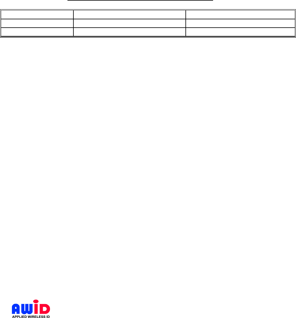
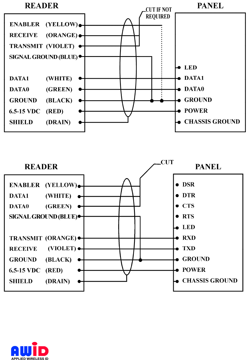
3.7 WIRING DIAGRAMS
See Figure 1 for wiring using Wiegand output to the host panel, Figure 2 for using RS-
232 to the control device, or Figure 3 for a combination of them.
LR-911 2.6H3
AWID PROPRIETARY
Page 11 9/26/2007
The Reader’s Blue wire is Signal Ground. It must be connected to the signal-return at
the panel or reader-input module. This is commonly (but not always) the panel ground
terminal.
Figure 1 Wiegand Output Format
Figure 2 RS-232 Output Format
The Reader’s Yellow wire enables the Reader to function only when this line is pulled
low (0 V) by a dry contact or by connection to ground. The Yellow wire must be
connected to either (a) a vehicle-sensing switch (if used), which is at ground potential
LR-911 2.6H3
AWID PROPRIETARY
Page 12 9/26/2007
when a vehicle is present, or (b) a permanent ground, for example, the Reader’s black
wire.
Figure 3 RS-232 & Wiegand Output Format

LR-911 2.6H3
AWID PROPRIETARY
Page 13 9/26/2007
4 INSTALLATION PROCEDURE
Verify that all items listed in section 4.1 of this manual are present before starting the
installation.
4.1 PARTS LIST
a. Installation Instructions (packed inside Reader carton) Qty=1
b. Sentinel-Prox LR-911 Reader Qty=1
(Tags for the LR-911 Reader and Installation Kit are available separately)
4.2 INSTALLATION STEPS
a. Locate the Reader (Item b on Parts List) at the desired mounting position on a
mounting post or a mounting surface. For mounting on a flat surface, drill four
small holes through the aluminum plate behind the Reader housing for mounting
screws, and one clearance hole for reader cable. For flexible mounting, use a
video camera adjustable mount or clamps. The installer determines the size of the
mounting holes and the clearance hole.
b. Install the tags on the selected surface, for example, inside vehicle windshields or
on the side of bins, pallets, truck trailers, etc.
c. Use the LR Installation Kit to provide audible and visible feedback as the tags are
attached and the Reader is aimed at the tags.
d. For Wiegand output, connect the Reader and the Panel together by cable
according to Figure 1. For RS-232 data format, see Figure 2. For simultaneous
outputs, see
Figure 3.
4.3 VERIFICATION
a. Connect the SP-6820-LR test unit, which is part of the LR Installation Kit, to the
Reader cable. Use the wiring list in the Installation Instructions. Apply power to
the reader and the test unit, using the plug-in DC power module in the Installation
Kit.
b. Use either a Prox-Linc WS tag that is attached firmly by its adhesive to a
rectangle of windshield glass, or a Prox-Linc MT tag for verification. Hold the tag
so that the hand does not interfere with direct line-of-sight between the tag and
the Reader.
c. Move the tag into the field. Observing the SR-6820-LR test unit, there is a brief
LED color change and a beep to indicate each read of the tag by the Reader.
Reads will repeat at a rate that is determined by the Reader’s firmware.
d. Move the tag from side to side, and at varying distances from the front of the
Reader housing, to determine the space in which the tag and Reader are active.
4.4 MOUNTING

LR-911 2.6H3
AWID PROPRIETARY
Page 14 9/26/2007
a. Check to ensure that all connections are secure. Feed all wires through the cable
access hole to the rear or the side of the mounting position.
b. Mount the Reader using fasteners on the aluminum plate to which the LR-911
Reader is attached. Drill holes through the plate as required by the application,
or attach flexible mounting devices or clamps.
c. Adjust the position or the angle of the Reader so that the tags (which have been
fastened by adhesive to the windshield or other surface) are detected and read at
the desired distance from the Reader.