Applied Wireless Identifications Group SR2400A Low power transmitter User Manual manual
Applied Wireless Identifications Group Inc. Low power transmitter manual
manual

Reader Description Revision G
June 09, 2006
The Sentinel
-
Prox SR
-
2400 Reader is a radio
-
frequency proximity reader for Access Control Systems.
The Reader consists of a transmit/receive antenna and reader electronics in a polycarbonate hou
sing.
The reader electronics and antenna are potted with epoxy resin to protect against the environment.
The Reader may be mounted on a metal doorframe, a window mullion, or any surface (wall, cabinet, etc.).
Parts List
(a
)
Installation sheet, P/N 002
-
98
-
A
Qty=1
(b)
Sentinel
-
Prox SR
-
2400 Reader, P/N 002
-
20
-
A
Qty=1
(c)
#6
-
32 x 1” thread
-
cutting screw, Type 23, P/N 616PPN23ZP
Qty=2
(d)
Screw
-
hole plug, P/N 002
-
27
-
A
Qty=3
(1 spare)
Installation Procedure
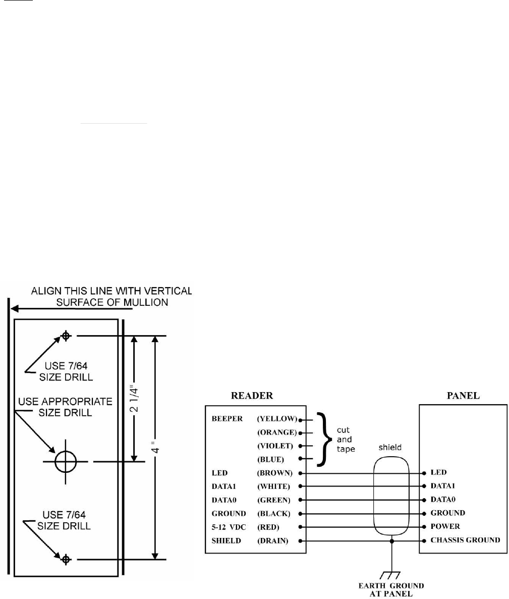
1.
Position the reader
(item b in the Parts List) at the desired location. Observe ADA height requirements.
Drill two 7/64 (0.109)
-
inch holes for the reader screws, and one clearance hole for the cable (see Figure 1).
2.
Clip off the white connector from the end of the re
ader’s cable. Keep the wires as long as possible.
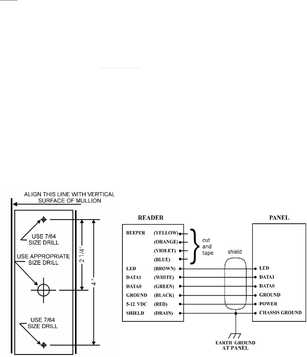
3.
Connect the reader’s cable to the access control panel as shown in Figure 2.
Connect the
yellow
wire only if used for Beeper control by the panel.
Do not connect
the
orange
,
blue
and
violet
wires to anythi
ng.
Tape or cap the unused wires singly.
4.
Use a linear regulated DC power source, between 5 volts (40 mA peak) and 12 volts (70 mA peak).
5.
Install the reader on the doorframe or other surface. Attach the reader to the doorframe with supplied screws
(item c
in the Parts List) or with adhesive or sealant.
6.
Power up the reader. The LED should be steady Amber. (The beeper does not sound.)
7.
Present a valid AWID proximity credential (card, keytag, or wafer) briefly to the reader. The beeper sounds
a
Long
-
Long
-
Short
sequence. The LED is steady Red to indicate standby mode. The reader is now initialized and
can read cards.
Note
: All credentials must be AWID’s own products.
8.
The LED color in standby may be changed from Red to Green, or from Green to Red,
using a
Color Changer
card, available from AWID. Remove power from the reader for a few seconds, then restore power.
While the LED is Amber, present the Color Changer card to toggle the LED color at standby.
9.
When installation is complete, in
sert screw
-
hole plugs (item d in the Parts List) into the screw clearance holes
to conceal the screw heads. Note: Screw
-
hole plugs are for one
-
time use. After they are seated, they cannot
be removed without damaging the plugs.
Product Specific
ations
Cable to Controller (for basic connections)
·
5 or 6 conductors (not twisted pairs), stranded, 22 AWG, color
-
coded insulation, overall 100% shielded
(Number of conductors depends upon use of optional features
–
Beeper and LED. See Figure 2.)
·
Length f
or Wiegand interface
................................
...
Up to 500 feet
Read Range with AWID Card (Metal
-
Compensated)
·
At 5 VDC
................................................................
.....
Typically 4 inches (10 cm)
·
At 12 VDC
................................................................
...
Typically 5.5 inches (14 cm)
Characteristics
·
Indoor and Outdoor
................................
...................
UL Listed
·
Operating Temperature Range
................................
.-
35
°
C to 65
°
C (
-
31
°
F t
o 150
°
F)
·
Operating Humidity
................................
...................
0 to 95% non
-
condensing
(continued)
Installation Sheet (Wiegand Interface)
(Part No. 002
-
98
-
A)
Sentinel
-
Prox SR
-
2400 Reader
SR
-
2400 Revision G Reader Installation Sheet
09 June 2006
Page 2 of 2
Operating Parameters
·
Excitation Frequency
................................
.................
125 kHz
·
Wiegand Output
..........................................................
26 bits to 50 bits (determined by code in credentials)
Certifications
................................................................
...............
UL 294 Listed; FCC Part 15 certification;
Industry C
anada; CE
Notes
1.
When wiring the reader, connect the black wire (ground) first, and the red wire (power) last.
2.
When the yellow wire is not used, the beeper remains active and under the reader’s internal control.
3.
The Beeper and LED lines are logic levels.
N
ever
apply power to them. They may be pulled to a low level
(0 to 1.2 VDC) to enable their function, and left floating at a high level (3.6 to 5.0 VDC) when not used.
4.
SR
-
2400 readers have Wiegand
-
protocol electrical interface only. (There
is no RS
-
232 interface.)
5.
For additional information, please visit AWID’s web site (
www.awid.com
).
Send all technical support questions to
support@awid.com
.
Call AWID at
1
-
800
-
369
-
5533
from 8:00 a.m. to 7:00 p.m. Eastern Time.
6.
This equipment has been tested and found to be in compliance with the limits for FCC part 15, Class A digital device.
These limits are designed to provide reasonable protection against harmful interference w
hen the equipment
is operated in a commercial environment. This equipment generates, uses and can radiate radio frequency energy and,
if not installed and used in accordance with instruction manual, may cause harmful interference with radio
communications. Operation of this equipment in a residential area is likely to cause harmful interference in which
case the user will be required to correct the interference at his own expense.
The users are prohibited from making any change or modificat
ion to this product. Any modification to this product
shall void the user’s authority to operate under FCC Part 15 Subpart A Section 15.21 regulations.
This device complies with Part 15 of the FCC Rules. Operation is subject to the following two conditio
ns:
(1) This device may not cause harmful interference, and (2) this device must accept any interference received,
including interference that may cause undesired operation.
FIGURE 1: HOLES LOCATION
FI
GURE 2: WIRING DIAGRAM (WIEGAND)

Reader Description Revision G
June 09, 2006
The Sentinel
-
Prox SR
-
2400 Reader is a radio
-
frequency proximity reader for Access Control Systems.
The Reader consists of a transmit/receive antenna and reader electronics in a polycarbonate hou
sing.
The reader electronics and antenna are potted with epoxy resin to protect against the environment.
The Reader may be mounted on a metal doorframe, a window mullion, or any surface (wall, cabinet, etc.).
Parts List
(a
)
Installation sheet, P/N 002
-
98
-
A
Qty=1
(b)
Sentinel
-
Prox SR
-
2400 Reader, P/N 002
-
20
-
A
Qty=1
(c)
#6
-
32 x 1” thread
-
cutting screw, Type 23, P/N 616PPN23ZP
Qty=2
(d)
Screw
-
hole plug, P/N 002
-
27
-
A
Qty=3
(1 spare)
Installation Procedure
1.
Position the reader
(item b in the Parts List) at the desired location. Observe ADA height requirements.
Drill two 7/64 (0.109)
-
inch holes for the reader screws, and one clearance hole for the cable (see Figure 1).
2.
Clip off the white connector from the end of the re
ader’s cable. Keep the wires as long as possible.
3.
Connect the reader’s cable to the access control panel as shown in Figure 2.
Connect the
yellow
wire only if used for Beeper control by the panel.
Do not connect
the
orange
,
blue
and
violet
wires to anythi
ng.
Tape or cap the unused wires singly.
4.
Use a linear regulated DC power source, between 5 volts (40 mA peak) and 12 volts (70 mA peak).
5.
Install the reader on the doorframe or other surface. Attach the reader to the doorframe with supplied screws
(item c
in the Parts List) or with adhesive or sealant.
6.
Power up the reader. The LED should be steady Amber. (The beeper does not sound.)
7.
Present a valid AWID proximity credential (card, keytag, or wafer) briefly to the reader. The beeper sounds
a
Long
-
Long
-
Short
sequence. The LED is steady Red to indicate standby mode. The reader is now initialized and
can read cards.
Note
: All credentials must be AWID’s own products.
8.
The LED color in standby may be changed from Red to Green, or from Green to Red,
using a
Color Changer
card, available from AWID. Remove power from the reader for a few seconds, then restore power.
While the LED is Amber, present the Color Changer card to toggle the LED color at standby.
9.
When installation is complete, in
sert screw
-
hole plugs (item d in the Parts List) into the screw clearance holes
to conceal the screw heads. Note: Screw
-
hole plugs are for one
-
time use. After they are seated, they cannot
be removed without damaging the plugs.
Product Specific
ations
Cable to Controller (for basic connections)
·
5 or 6 conductors (not twisted pairs), stranded, 22 AWG, color
-
coded insulation, overall 100% shielded
(Number of conductors depends upon use of optional features
–
Beeper and LED. See Figure 2.)
·
Length f
or Wiegand interface
................................
...
Up to 500 feet
Read Range with AWID Card (Metal
-
Compensated)
·
At 5 VDC
................................................................
.....
Typically 4 inches (10 cm)
·
At 12 VDC
................................................................
...
Typically 5.5 inches (14 cm)
Characteristics
·
Indoor and Outdoor
................................
...................
UL Listed
·
Operating Temperature Range
................................
.-
35
°
C to 65
°
C (
-
31
°
F t
o 150
°
F)
·
Operating Humidity
................................
...................
0 to 95% non
-
condensing
(continued)
Installation Sheet (Wiegand Interface)
(Part No. 002
-
98
-
A)
Sentinel
-
Prox SR
-
2400 Reader
SR
-
2400 Revision G Reader Installation Sheet
09 June 2006
Page 2 of 2
Operating Parameters
·
Excitation Frequency
................................
.................
125 kHz
·
Wiegand Output
..........................................................
26 bits to 50 bits (determined by code in credentials)
Certifications
................................................................
...............
UL 294 Listed; FCC Part 15 certification; Industry Can
ada; CE
Notes
1.
When wiring the reader, connect the black wire (ground) first, and the red wire (power) last.
2.
When the yellow wire is not used, the beeper remains active and under the reader’s internal control.
3.
The Beeper and LED lines are logic levels.
Ne
ver
apply power to them. They may be pulled to a low level
(0 to 1.2 VDC) to enable their function, and left floating at a high level (3.6 to 5.0 VDC) when not used.
4.
SR
-
2400 readers have Wiegand
-
protocol electrical interface only. (The
re is no RS
-
232 interface.)
5.
For additional information, please visit AWID’s web site (
www.awid.com
). Send all technical support questions to
support@awid.com. Call AWID at
1
-
80
0
-
369
-
5533
from 8:00 a.m. to 7:00 p.m. Eastern Time.
6.
FCC Compliance: This equipment has been tested and found to be in compliance with the limits for FCC part 15,
Class A digital device. These limits are designed to provide reasonable protection again
st harmful interference when
the equipment is operated in a commercial environment. This equipment generates, uses and can radiate radio frequency
energy and, if not installed and used in accordance with instruction manual, may cause harmful interferenc
e with radio
communications. Operation of this equipment in a residential area is likely to cause harmful interference in which case
the user will be required to correct the interference at his own expense.
The users are prohibited from making any change
or modification to this product. Any modification to this product
shall void the user’s authority to operate under FCC Part 15 Subpart A Section 15.21 regulations.
This device complies with Part 15 of the FCC Rules. Operation is subject to the following
two conditions:
(1) This device may not cause harmful interference, and (2) this device must accept any interference received, including
interference that may cause undesired operation.
7.
Industry Canada Compliance: Operation is subjec
t to the following two conditions: (1) This device may not cause
harmful interference, and (2) this device must accept any interference, including interference that may cause undesired
operation of the device.
FIGURE 1: HOLES LOCATION
FIGURE 2: WIRING DIAGRAM (WIEGAND)