Apprion APP2X001 Wireless Access Point User Manual IONizer Reference Guide
Apprion, Inc. Wireless Access Point IONizer Reference Guide
Apprion >
Contents
- 1. 4000 Series Manual
- 2. 4100 Series Manual
- 3. 4200 Series Manual
- 4. 4300 Series Manual
4000 Series Manual

Apprion Proprietary and Confidential
IONizer 4000 Series
Hardware Installation Guide
Apprion Incorporated
March 2009

Apprion Proprietary and Confidential
Revision History
Date
Document Revision
Author(s)
June 08
Version 1
David Cote
October 08
Version 2
David Cote
January 09
Version 3
David Cote
February 09
Version 4
David Cote
March 09
Version 5
David Cote

Table of Contents
Apprion Proprietary & Confidential
iii
Table of Contents
Revision History ............................................................................................................................................................ ii
Audience ........................................................................................................................................................................ v
Conventions ................................................................................................................................................................... v
How to Use this Guide ................................................................................................................................................ xv
CHAPTER 1 IONIZER DEVICE OVERVIEW ...................................................................................................... 1
Introduction ................................................................................................................................................................... 1
IONizer 4000 Series Models ......................................................................................................................................... 1
Safety Information ......................................................................................................................................................... 2
Compliance .................................................................................................................................................................... 3
CHAPTER 2 INSTALLATION PREPARATION ................................................................................................... 5
Overview ....................................................................................................................................................................... 5
Preparation ..................................................................................................................................................................... 5
Packaging Content .................................................................................................................................................... 5
4000 Series ............................................................................................................................................................................. 5
CHAPTER 3 INSTALLATION GUIDELINES ....................................................................................................... 7
Overview ....................................................................................................................................................................... 7
Basic Guidelines ............................................................................................................................................................ 7
CHAPTER 4 MOUNTING METHODS ................................................................................................................... 9
Overview ....................................................................................................................................................................... 9
Pole Mounting ............................................................................................................................................................... 9
Requirements ......................................................................................................................................................................... 9
Mounting Diagram ............................................................................................................................................................... 10
Wall Mounting ............................................................................................................................................................ 10
Requirements ....................................................................................................................................................................... 10
Procedure ............................................................................................................................................................................. 10
Sealing Antenna Connections ...................................................................................................................................... 12
CHAPTER 5 GROUNDING AND CABLING THE IONIZER ........................................................................... 13
Overview ..................................................................................................................................................................... 13
Grounding .................................................................................................................................................................... 13
Grounding Procedure .............................................................................................................................................. 13
IONizer Cabling .......................................................................................................................................................... 14
Using 48V PoE (All models in series) .................................................................................................................... 14
Using 48V PoE from an iKIT ................................................................................................................................. 14
Using 24V Input Power .......................................................................................................................................... 15
Wiring the Supplied Power Source Connector ..................................................................................................................... 16
Connecting the IONizer to the Network ............................................................................................................................... 17
APPENDIX A APPROVED ANTENNAS .............................................................................................................. 19
Basic Antenna Installation Information ....................................................................................................................... 19
Sealing Antenna Connections ................................................................................................................................. 19
Approved Antennas ..................................................................................................................................................... 20
Omni-Directional Antennas .................................................................................................................................... 20
Polarized Antennas ................................................................................................................................................. 27

Table of Contents
Page iv
Apprion Proprietary & Confidential
Directional Antennas .............................................................................................................................................. 29
APPENDIX B IONIZER 4000 SPECIFICATIONS ............................................................................................... 31
Specifications .............................................................................................................................................................. 31

Audience and Conventions
Apprion Proprietary & Confidential
v
Audience
This document describes Apprion™ Incorporated’s (Apprion’s) IONizer Installation instructions and is
intended for the following audiences:
Apprion Employees (Full time and Contract)
This document is a product of the Apprion Engineering team and may be used to help other Apprion
employees gain a better understanding of the IONizer installation process.
Apprion Services Group
This document is intended for use by the Apprion Services Group to aid in the installation of IONizer
devices.
Apprion’s Outsourced Documentation Team
This document is intended to serve as input for other customer/partner-facing documentation that may
be produced by Apprion’s outsourced documentation team.
This document is Apprion PROPRIETARY AND CONFIDENTIAL.
Conventions
Item
Description
Arial Bold
Menu Instructions (Device > View Devices)
Tab Names (View Devices)
Buttons (Submit)
Bold
Field Name (Device Type)
Note
Courier Type
Keystroke Entry (Search Term)
Command Line Examples (activate_config)
Italic
Names of referenced documents (ION User Guide)

How to Use This Guide
Apprion Proprietary & Confidential
xv
How to Use this Guide
This guide provides basic instructions on how to install and wire an IONizer device. You should read ALL
chapters for important information before attempting the installation.
Chapter 1 – IONizer Device Overview
Apprion Proprietary and Confidential
Page 1
Chapter 1
IONizer Device Overview
Introduction
This guide provides information on how to install Apprion™ IONizer devices. The IONizer provides an
integrated set of modular hardware and software services that facilitate creation, control and
monitoring of secure device networks for the modern plant. The IONizer is a wireless transceiver that
serves as the center point of an independent wireless network, or as the connection point between
wireless and wired networks. Designed for the industrial applications market, IONizer models are IEEE
802.11a/b/g/i/j compliant depending on the radios installed. This platform is specifically designed to
address the wireless connectivity needs of high-security industrial environments.
All IONizer devices are remotely configured and all can take on one or more forms within the network.
This means that each IONizer can be configured to suit client requirements.
This guide deals with installation only. Configuration instructions are provided in the IONizer Reference
Guide.
IONizer 4000 Series Models
IONizers in the 4000 Series are designed for deployment in ordinary locations and may be mounted
indoors or outdoors. These devices cannot be deployed in hazardous locations. IONizers can be ordered
with one or two radios. In addition, some IONizers in this series contain a WiHART gateway. All models
are capable of being powered by 48 VDC PoE or 24 VDC external power.
WARNING: IONizer 4000 Series devices are to be used in ordinary locations only. Installation
in an operating atmosphere that is not certified for the device could result in an explosion
that could cause death or serious injury.
The IONizers in this series come in different configurations based on Model Number.
IONizer models in this series include:
IONizer 4000-200 (Single Radio)
IONizer 4000-220 (Two Radios)
IONizer 4020-200 (Single Radio, Embedded WiHART)
IONizer 4020-220 (Two Radios, Embedded WiHART)
All IONizer s use 48V Power over Ethernet (PoE) or 24V external power. The IONizer 4020 is identical to
the 4000 but also contains an embedded WiHART gateway.
Section 1 – IONizer Device Overview
Page 2
Apprion Proprietary & Confidential
FCC regulations require that IONizer devices be professionally installed by an installer
certified by the National Association of Radio and Telecommunications Engineers or
equivalent institution.
Safety Information
The FCC, with its action in Docket 96-8 has adopted a safety standard for human exposure to radio
frequency (RF) electromagnetic energy emitted by FCC certified equipment. When used with approved
Apprion antennas, the IONizer 4000 products meet the uncontrolled environmental limits found in OET-
65 and ANSI C95.1, 1991. Proper installation of this radio product according to the instructions found in
this guide will result in user exposure that is substantially below the FCC recommended limits.
CAUTION: Do not touch or move antenna(s) while the unit is transmitting or receiving.
CAUTION: Do not hold any component containing a radio such that the antenna is very
close to, or touching any exposed parts of the body, especially the face and eyes, while
transmitting.
CAUTION: Do not operate the radio or attempt to transmit data unless the antenna is
connected. Damage could occur.
WARNING: Do not operate a portable transmitter near unshielded blasting caps or in an
explosive environment unless it is a type specifically qualified for such use.
WARNING: To comply with FCC RF exposure compliance requirements, the antennas used
with the IONizer must be installed with a minimum separation distance of 25.26 cm from
all persons, except the 16 dBi Sector Antenna (Apprion P/N 89-1186-000) and the 19 dBi
Directional Antenna (Apprion P/N 89-1187-000) which must be installed with a minimum
separation distance of 48.97 cm from all persons.
The 16 dBi Sector Antenna (Apprion P/N 89-1186-000) and the 19 dBi Directional Antenna
(Apprion P/N 89-1187-000) are to be used for Point-to-Point operation only.
Antennas must not be co-located or operated in conjunction with any other antenna
transmitter unless separated by 20 cm or greater.
CAUTION: 5150 – 5250 MHz frequency band is for indoor use only.
Chapter 1 – IONizer Device Overview
Apprion Proprietary and Confidential
Page 3
CAUTION: High power radar devices are the primary users in the 5250 – 5350 MHz and
5650 – 5850 MHz frequency bands. These radar devices may cause interference and/or
damage to LELAN devices.
WARNING: The IONizer 4000 is intended for local (intra-building) connections only and is
not designed or evaluated for direct connections to the public telecommunications/cable
distribution systems. Cable and Ethernet connections should be made in accordance to the
National Electrical Code (NEC). For example, one of the following should be true:
Cable runs are located in the same building as the unit
Cable runs through air outside of buildings are less than 140 feet (42 m), and are
not routed near power lines
Cable runs between buildings are buried
Cable runs between buildings are in underground conduit, where a continuous
metallic cable shield or a continuous metallic conduit containing the cable is
bonded to each building grounding electrode system.
These options come from the US National Electrical Code, Sections 800.10, 800.12, 800.31,
800.32, 800.33, and 800.40.
WARNING: Do not open an IONizer when an explosive atmosphere may be present.
CAUTION: Risk of explosion if battery is replaced by an incorrect type. Replace only with
Snap-On battery assemblies that are designed for use with the Texas Instrument M4T32-
BR12SH6 module. Dispose of used batteries according to the manufacturer’s instructions.
Compliance
This equipment has been tested and found to comply with the European Telecommunications Standard
ETS 300 328. This standard covers Wideband Data Transmission Systems referred to in CEPT
recommendation T/R 10.01. This type of equipment is designed to provide reasonable protection
against harmful interference when the equipment is operated in a commercial environment. This
equipment generates, uses, and can radiate radio frequency energy and, if not installed in accordance
with the instruction guide, may cause harmful interference to radio communications.
This equipment complies with Part 15 of the FCC Rules. Operation is subject to the following two
conditions. (1) The device may not cause harmful interference, and (2) this device must accept any
interference received, including interference that may cause undesired operation.
Chapter 2 – Installation Preparation
Apprion Proprietary and Confidential
Page 5
Chapter 2
Installation Preparation
Overview
This chapter describes the installation process and what you’ll need to successfully mount and connect
an IONizer at your site.
Preparation
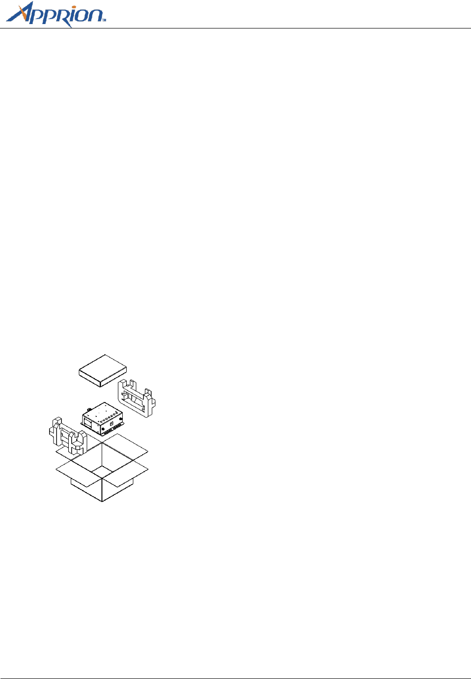
The IONizers come packaged in specialized shipping containers, each designed for the type of IONizer
ordered.
Packaging Content
Contents of the package depend on the IONizer purchased.
4000 Series
IONizer 4000 or 4020
Mounting Hardware ( 2 U-bolts with associated hardware, 4 wall anchor bolts)
24V Power Connector
Manual
Product Registration and Warranty Cards
Additional orderable accessories include:
Chapter 2 – Installation Preparation
Page 6
Apprion Proprietary & Confidential
Antenna(s) based on configuration
Power over Ethernet (PoE) Injector with AC Power Cord
Multiple length PoE Cable
Additional Ethernet Cable
Specialized mounting brackets and hardware
Inspect the unit for any damage or missing items. Contact your Apprion service representative for
support.
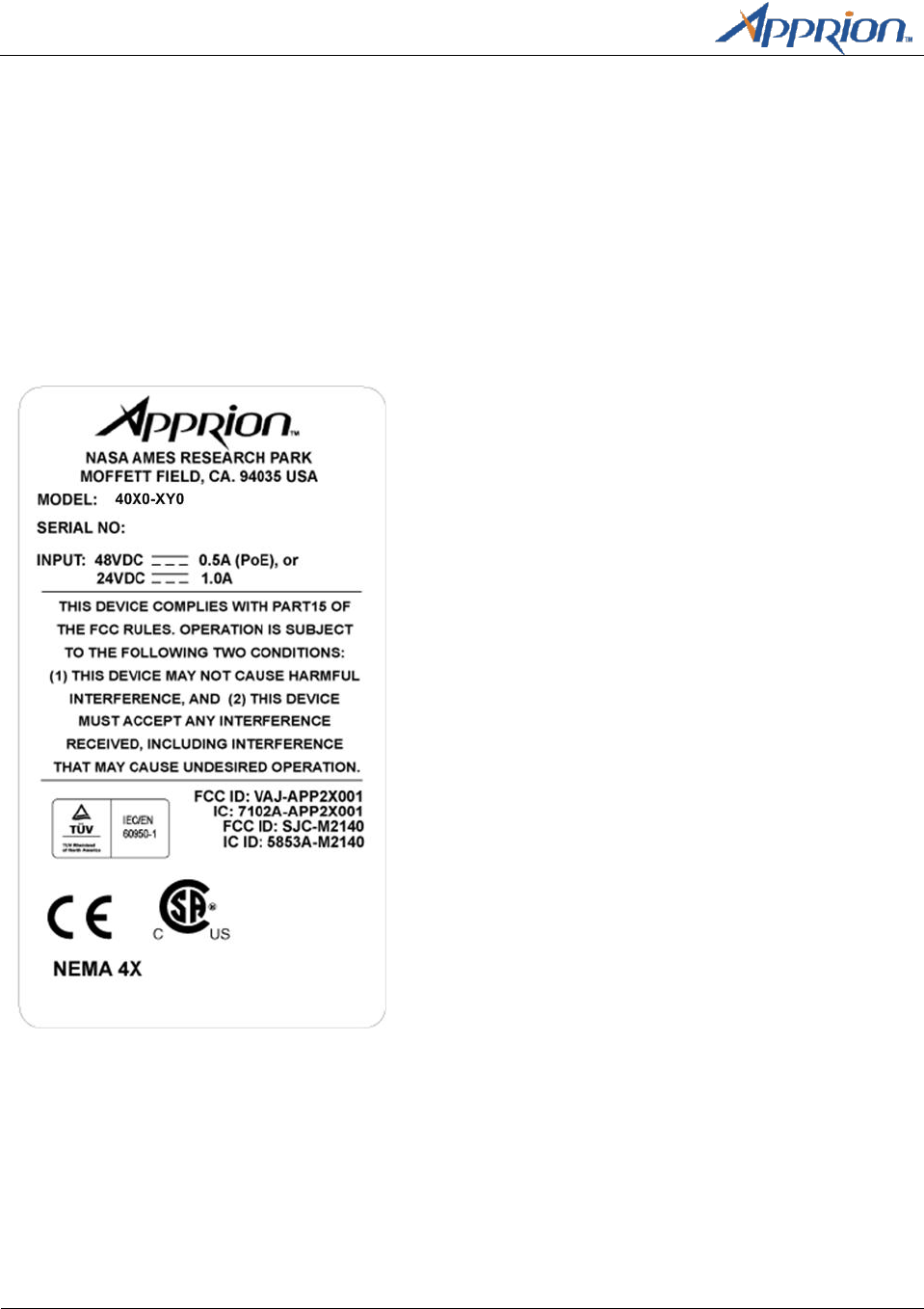
Ensure that the nameplate on the IONizer your purchased indicates the correct model ordered.
Note: Models that use this nameplate include: 4000-200, 4000-220, 4020-200, and 4020-220.

Chapter 3 – Installation Guidelines
Apprion Proprietary and Confidential
Page 7
Chapter 3
Installation Guidelines
Overview
The IONizer is intended to be installed as part of a complete wireless design solution. IONizer’s can be
mounted just about anywhere including high posts to achieve the best results.
This chapter provides basic guidelines that pertain to each device.
Basic Guidelines
If mounted outdoors, the exposed PoE cable to the IONizer device must not exceed 140 feet (42
meters).
WARNING: Installing the IONizer 4000 with a length of exposed PoE or secondary Ethernet cable
greater than 140 feet (42 meters) can cause severe damage to the unit or supplementary
equipment during a lightning strike.
Cable routed through conduit has a maximum length restriction of 300 feet (91 meters).
To comply with FCC RF exposure compliance requirements, the antennas used with the IONizer
must be installed with a minimum separation distance of 25.26 cm from all persons, except the
16 dBi Sector Antenna (Apprion P/N 89-1186-000) and the 19 dBi Directional Antenna (Apprion
P/N 89-1187-000) which must be installed with a minimum separation distance of 48.97 cm
from all persons.
The 16 dBi Sector Antenna (Apprion P/N 89-1186-000) and the 19 dBi Directional Antenna
(Apprion P/N 89-1187-000) are to be used for Point-to-Point operation only.
Antennas must not be co-located or operated in conjunction with any other antenna transmitter
unless separated by 20 cm or greater.
Installation must be performed using authorized cables and/or connectors provided with the
device or available from the manufacturer/distributor for use with this device.
Changes or modification no expressly approved by the manufacturer or responsible party for the
FCC compliance could void the user’s authority to operate this equipment.
Maintenance is limited to the external enclosure surface and cable connections. At no time
should the unit be opened.
IONizer’s mounted outdoors must be grounded with a connection of 1 OHM or less leading from
the external grounding stud to earth ground. When mounted indoors, the unit should be
grounded to the building’s earth ground via a connection to the external grounding stud (if
practical). Follow all national, local, and plant electrical codes.

Chapter 2 – Installation Preparation
Page 8
Apprion Proprietary & Confidential
IONizer’s must be properly grounded before making any other power and signal connections.
Ionizer’s must always be grounded in a hazardous location as defined by the NEC or applicable
local and country codes.

Chapter 4 – Mounting Methods
Apprion Proprietary and Confidential
Page 9
Chapter 4
Mounting Methods
Overview
This chapter describes various mounting methods. Your actual installation will dictate the actual way
your device is mounted.
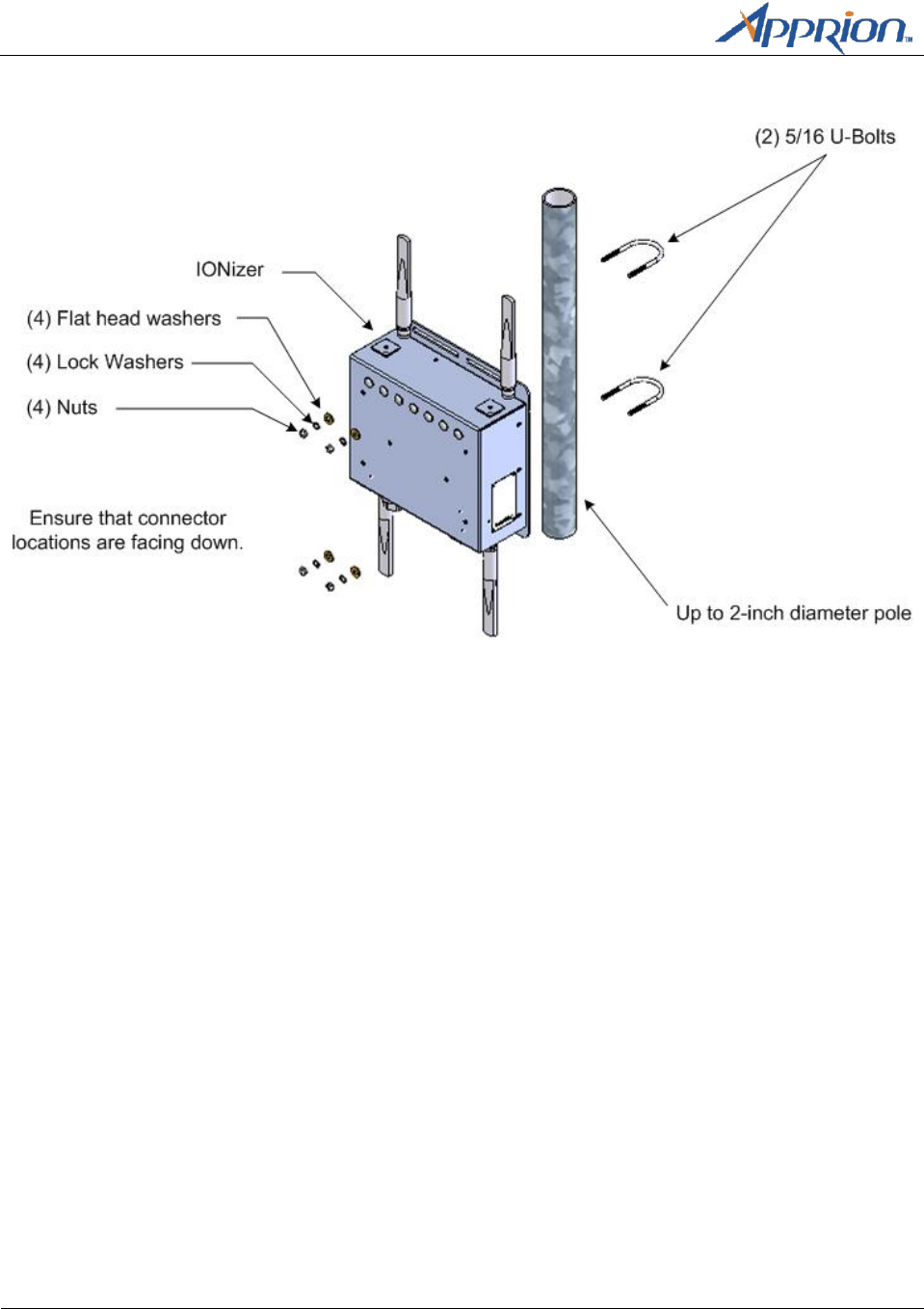
Pole Mounting
Requirements
3/8-inch torque wrench
½-inch socket head
(2) 5/16 U-bolts (supplied)
(4) Split washers (supplied)
(4) Flat head washers and nuts (supplied)
The IONizer can be mounted on vertical poles up to 2 inches in diameter using the U-bolt hardware
provided with the device. The device must be mounted in the correct orientation with device
connectors on the bottom facing the ground.
Chapter 4 – Mounting Methods
Page 10
Apprion Proprietary & Confidential
Mounting Diagram
Nut torque range is 25 to 30 inch pounds. Attach antenna cables after the device is mounted.
Wall Mounting
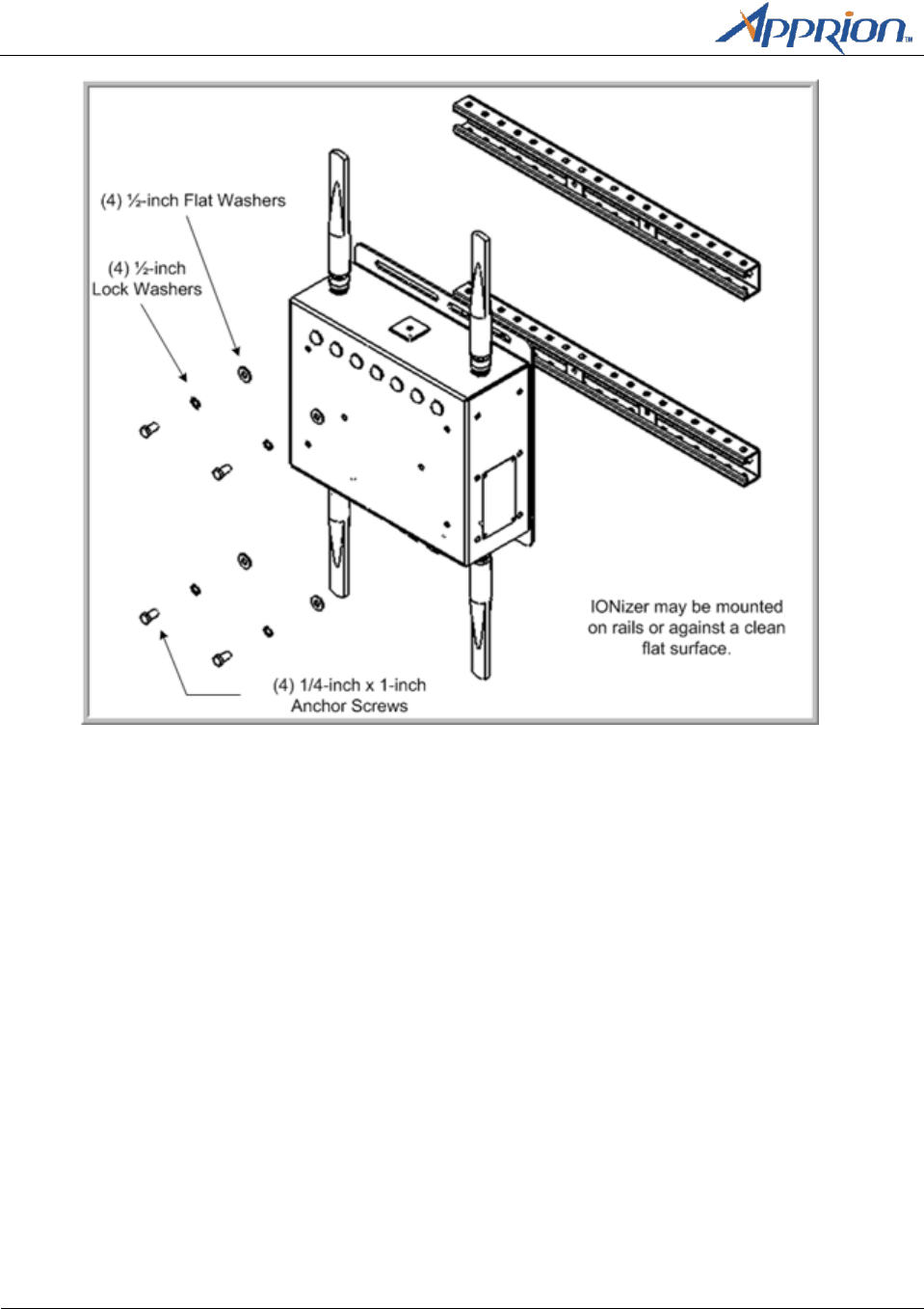
Requirements
(4) ¼-inch anchor screws (ELCO ¼-inch x 1-inch or equivalent)
(4) ¼-inch flat washers
3/8-inch power drill
¼-inch drill bit
Phillips head screwdriver
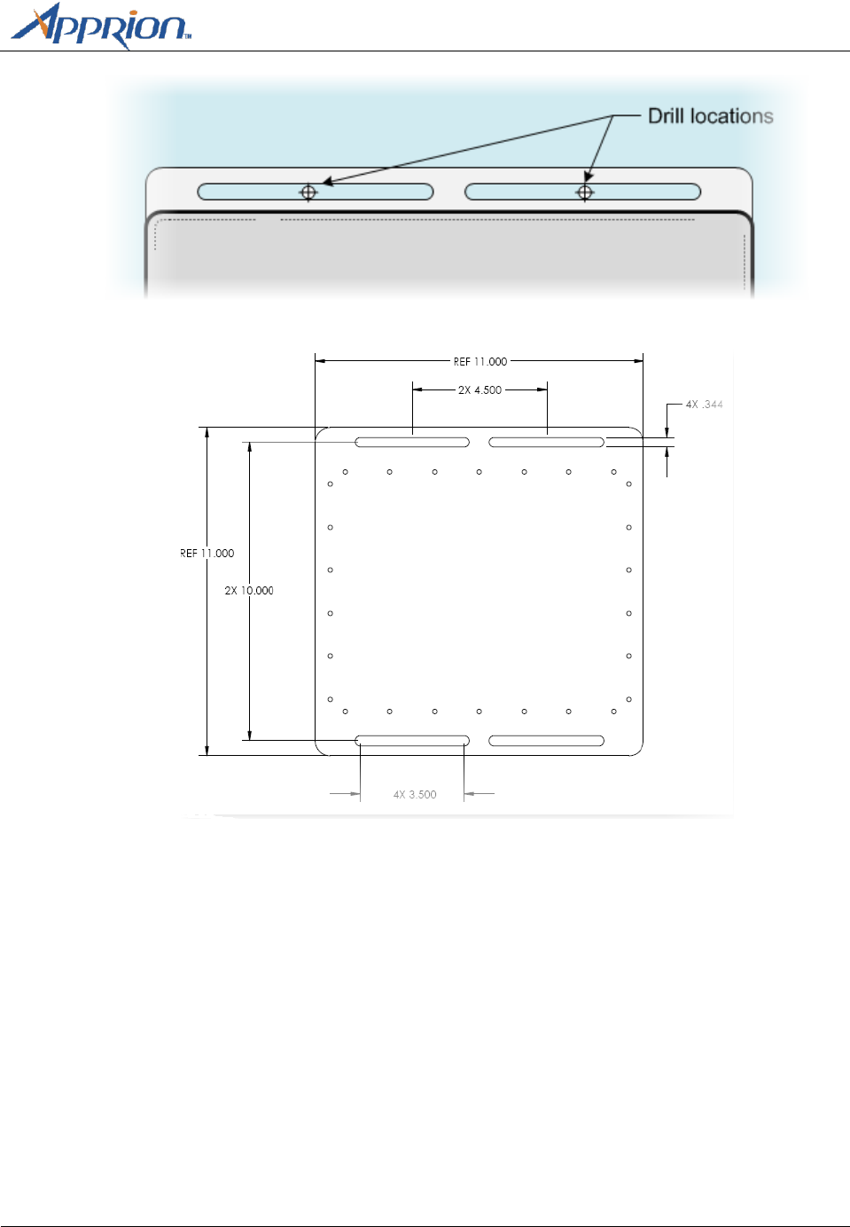
Procedure
1. Ensure that the surface is clean and free of loose debris.
2. Use the device as a template using the mounting slots to mark screw locations on the mounting
surface.
Chapter 4 – Mounting Methods
Apprion Proprietary and Confidential
Page 11
The exact dimensions are displayed in the following diagram:
3. Drill pilot holes using the recommended drill bit size.
4. Mount the device to the surface using the anchor screws and flat washers per manufacturer’s
instructions. The flat head washers should be between the unit mounting flange and the anchor
screw head.
5. You can also mount the IONizer on rails as shown:
Chapter 4 – Mounting Methods
Page 12
Apprion Proprietary & Confidential
6. Seal antenna connections (see instructions).
Sealing Antenna Connections
Antenna connections should be sealed to protect them from exterior harsh environments. Use a self-
amalgamating poly isobutylene tape, which over a period of time adheres to itself and forms a single
amalgameted rubber molding that conforms to the shape of the item its covering. Once the tape is in
place for several hours, the rubber molding is resistant to water and most solvents. It remains stable
over a wide temperature range and degrades very slowly in sunlight. The tape can be removed by
cutting it away with a sharp knife.
Chapter 5 – Grounding and
Cabling the IONizer
Apprion Proprietary and Confidential
Page 13
Chapter 5
Grounding and Cabling the IONizer
Overview
This chapter provides the cabling procedures for the IONizer 4000.
Grounding
All IONizers must be properly grounded before making power and signal connections. Apprion
recommends a UL Listed #10 AWG wire that is suitable for this purpose, and a ring tongue terminal,
Panduit P/N P10-8R or equivalent. The terminal is to be crimped to the wire using the correct crimping
tool as recommended by the terminal manufacturer. The torque rating on the nut is 8 to 10 inch
pounds. The wire should be kept as short as possible while using grounding practices that are compliant
with local codes and practices.
Note: Ensure that the connection to a proper earth ground is made by certified and authorized
personnel. The ground must conform to all applicable codes and regulations. The materials required to
connect to a proper earth ground are defined by local conditions and must be procured locally to ensure
that the correct safety environment is achieved.
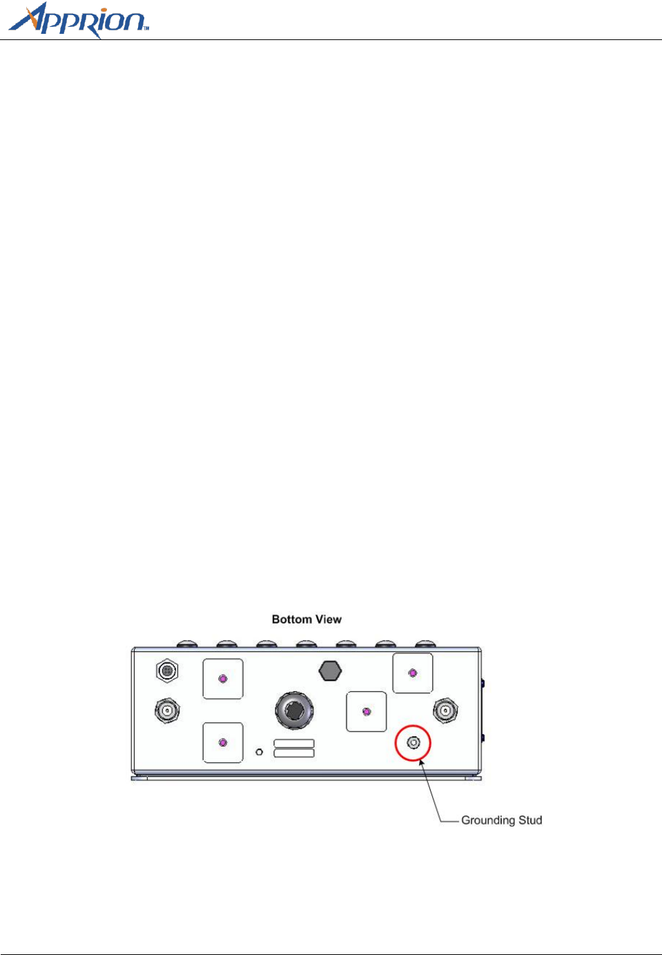
Grounding Procedure
The grounding stud is located on the bottom of the IONizer at the location shown:
Bottom view of IONizer 4020
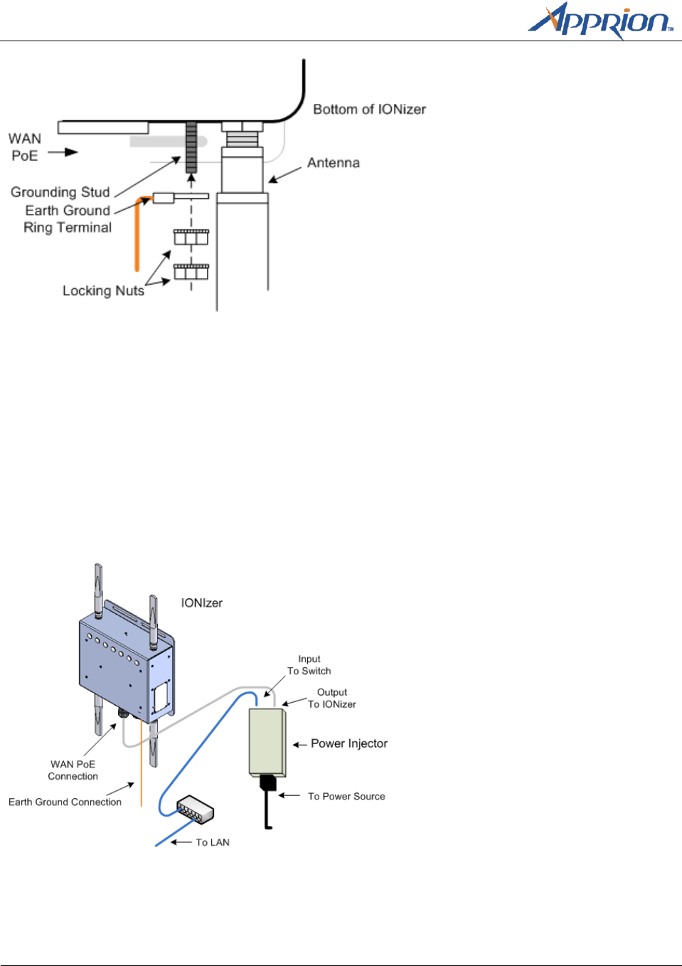
Attach the earth ground wire (not supplied) to the ring terminal attached to the IONizer’s grounding
stud. Ensure that the ring terminal is seated against the IONizer’s metal case.
Chapter 5 – Grounding and
Cabling the IONizer
Page 14
Apprion Proprietary & Confidential
IONizer Cabling
The IONizer can get its power using a 48v PoE for power and Ethernet connection to the network. In
addition, a 24V connection is also available. The IONizer can also be connected to a PoE injector or get
its power from an Apprion iKIT. This section describes all cabling methods.
Using 48V PoE (All models in series)
This IONizer uses a 48v PoE cable for power and Ethernet connection to the network. Connect cabling
between the PoE injector, the IONizer, and the network as shown.
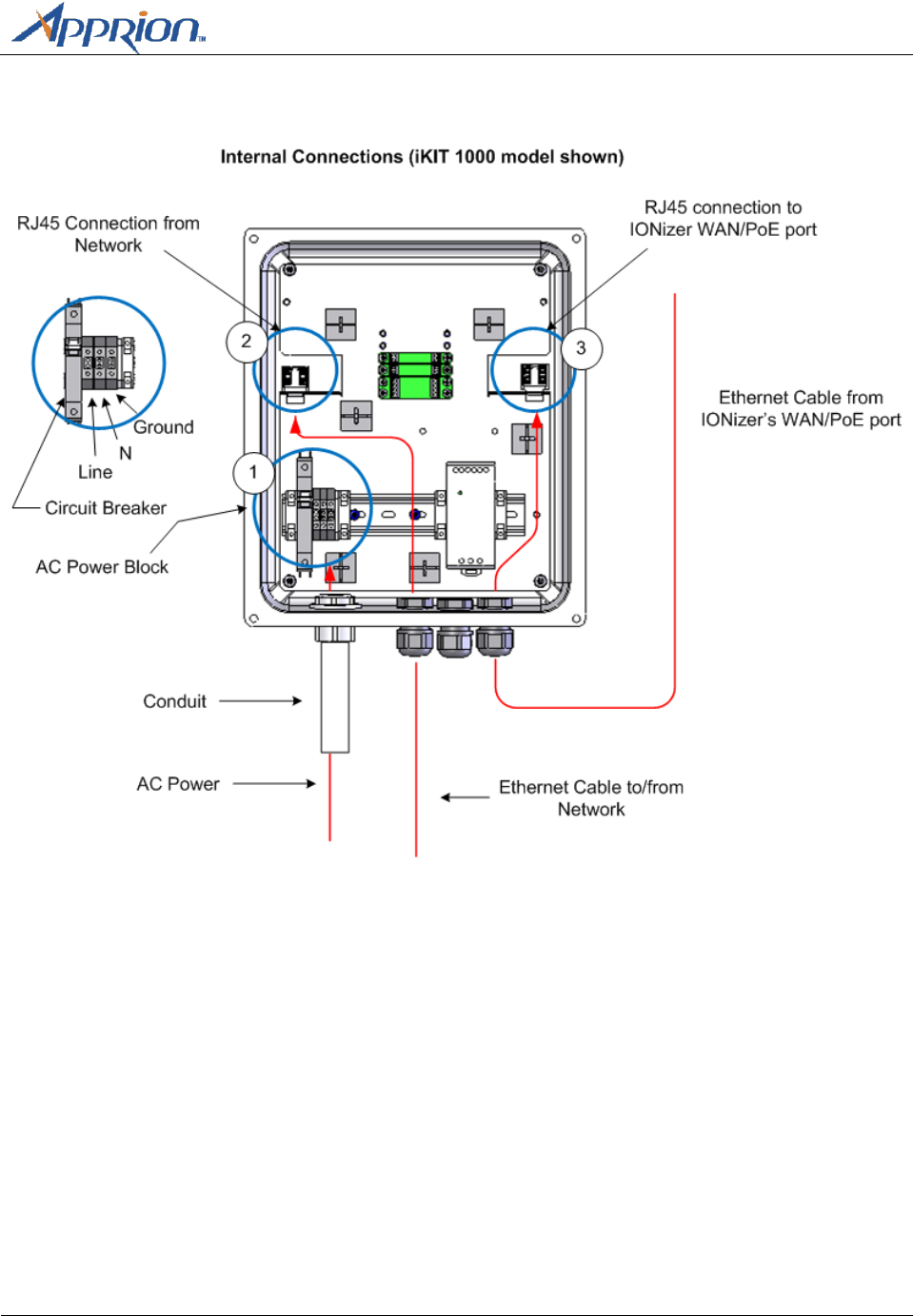
Using 48V PoE from an iKIT
The IONizer can also be connected to different versions of the Apprion iKIT which supply power and
Ethernet. The iKIT provides a convenient way to cable an IONizer especially in areas where power and
network cabling is a long distance from the IONizer. This method provides PoE but also provides surge
Chapter 5 – Grounding and
Cabling the IONizer
Apprion Proprietary and Confidential
Page 15
and lightning protection for data and power. See the appropriate iKIT Installation Guide for complete
iKIT details.
Note: There are various iKITs available to suit your installation. This diagram shows the base model iKIT.
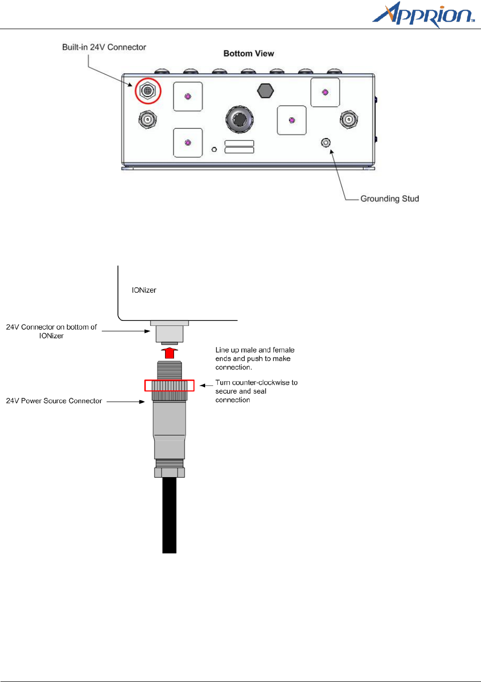
Using 24V Input Power
The IONizer allows you to also power the unit with 24V input power. When using 24V power, you will
make your Ethernet connections separately.
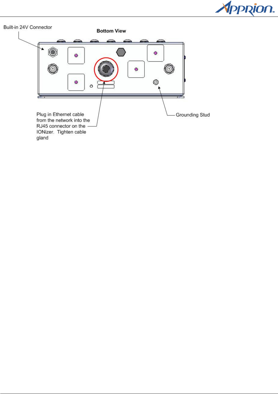
The bottom of the IONizer has a built-in 24V connector where shown:
Chapter 5 – Grounding and
Cabling the IONizer
Page 16
Apprion Proprietary & Confidential
IONizer 4020-XXX Model Shown
A 24V power source connector plug is included with the IONizer. This connector plug is used to connect
the 24V power to the IONizer through the built-in connector.
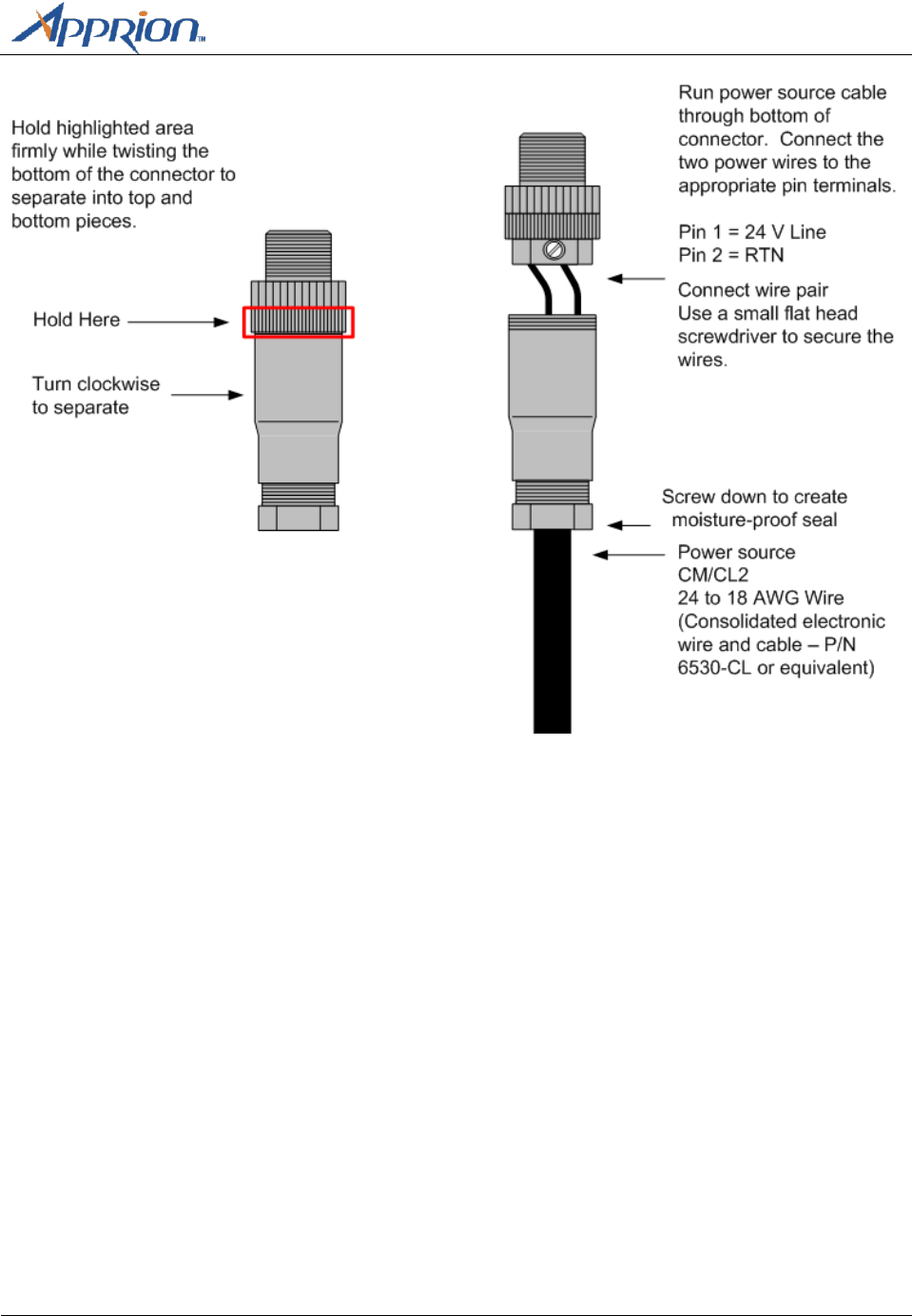
Wiring the Supplied Power Source Connector
If you did not order the 24V Power Source Connector with a power cable, you will have to wire the
connector yourself. The following diagram describes this process.
Chapter 5 – Grounding and
Cabling the IONizer
Apprion Proprietary and Confidential
Page 17
Once completed, reseat the top and bottom pieces of the connector and tighten the sealing nut at the
bottom of the connector. Use the procedures above to connect it to the IONizer.
Note: The Phoenix Connector Kit order number is 1662528
Connecting the IONizer to the Network
Connect the Ethernet cable from the network to the WAN port on the Ionizer. The Ethernet cable
should be run through the supplied cable gland on the IONizer. The WAN port of the IONizer contains an
RJ45 connector that allows you to plug in the network cable. Plug in the cable and secure the cable
gland to create a moisture-proof seal.
Chapter 5 – Grounding and
Cabling the IONizer
Page 18
Apprion Proprietary & Confidential
You can also use an iKIT if Ethernet cabling is more convenient or if you want data surge protection. See
the iKIT 1103 Installation Guide for details. However, in ordinary locations, an iKIT is not required.

Appendix A– Approved Antennas
Apprion Proprietary and Confidential
Page 19
Appendix A
Approved Antennas
Basic Antenna Installation Information
Screw on antennas until hand-tight.
The IONizer supports various antenna types. Antennas that ship with the units are based on
orders
Unauthorized antennas may cause damage to the device
To comply with FCC RF exposure compliance requirements, the antennas used with the IONizer
must be installed with a minimum separation distance of 25.26 cm from all persons, except the
16 dBi Sector Antenna (Apprion P/N 89-1186-000) and the 19 dBi Directional Antenna (Apprion
P/N 89-1187-000) which must be installed with a minimum separation distance of 48.97 cm
from all persons.
The 16 dBi Sector Antenna (Apprion P/N 89-1186-000) and the 19 dBi Directional Antenna
(Apprion P/N 89-1187-000) are to be used for Point-to-Point operation only.
Antennas must not be co-located or operated in conjunction with any other antenna transmitter
unless separated by 20 cm or greater.
Installation must be performed using authorized cables and/or connectors provided with the
device or available from the manufacturer/distributor for use with this device.
Changes or modifications not expressly approved by the manufacturer or responsible party for
this FCC compliance could void the user’s authority to operate this equipment
When installing authorized antennas, make sure that the N-Type connector is free of dirt and
moisture. The installer should properly ground themselves to minimize the chance of
electrostatic discharge or arc.
WARNING: Potential electrostatic charging hazard.
CAUTION: During all servicing and maintenance activities, the antennas must be handled with extreme
caution to minimize possible electrostatic discharge (ESD) and arcing events.
Sealing Antenna Connections
Antenna connections should be sealed to protect them from exterior harsh environments. Use a self-
amalgamating poly isobutylene tape, which over a period of time adheres to itself and forms a single
amalgameted rubber molding that conforms to the shape of the item its covering. Once the tape is in
place for several hours, the rubber molding is resistant to water and most solvents. It remains stable
over a wide temperature range and degrades very slowly in sunlight. The tape can be removed by
cutting it away with a sharp knife.
Appendix A – Approved Antennas
Page 20
Apprion Proprietary & Confidential
Approved Antennas
The following sections provide information on Apprion approved antennas for use with IONizer and
provides specifications on each.
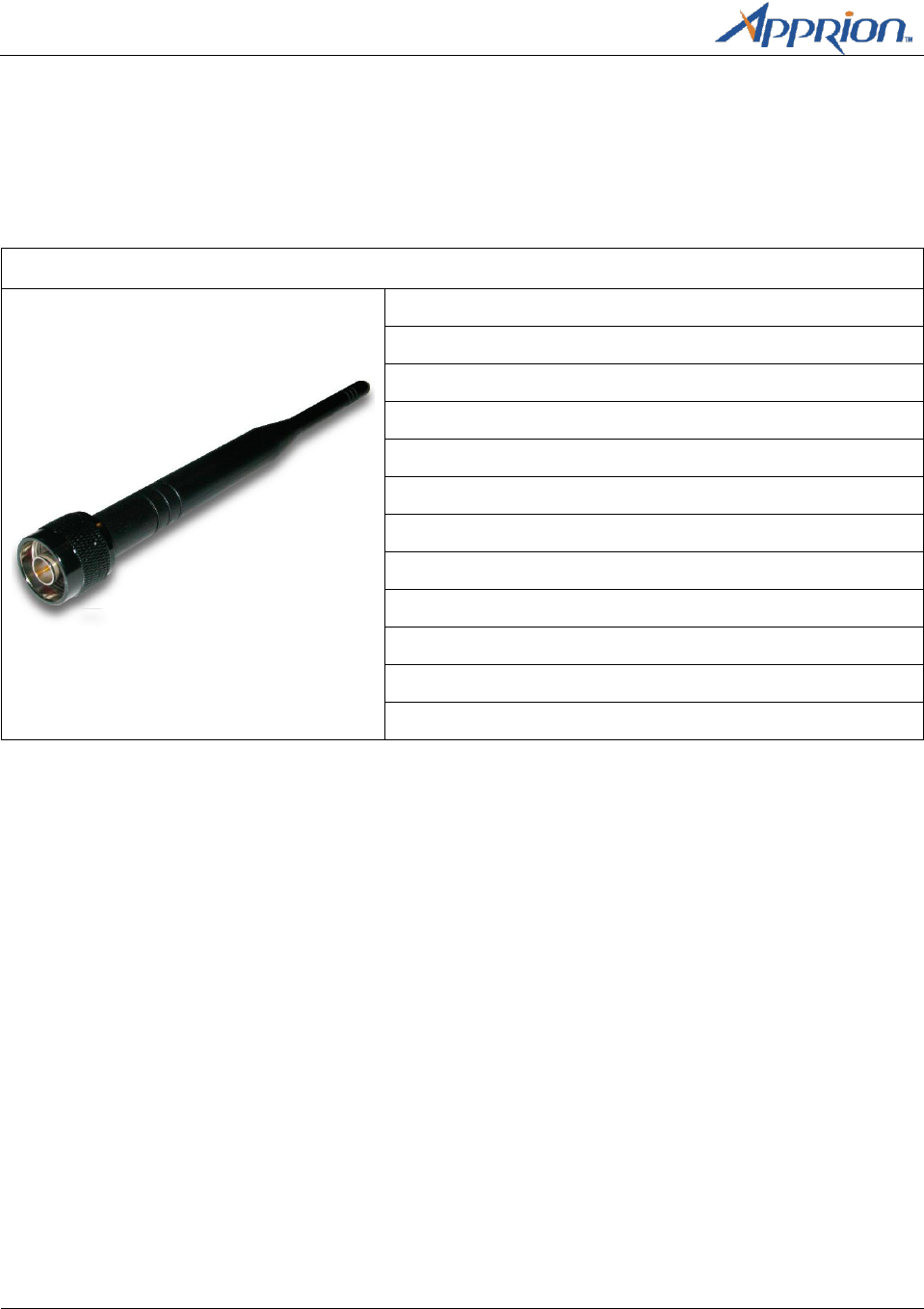
Omni-Directional Antennas
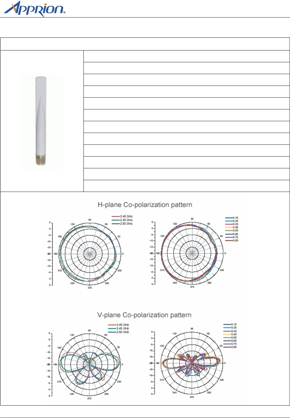
Dual Band Omni (Standard – 89-1584-000)
Typical VSWR: 2.0:1 max.
Impedance: 50 Ohm
Polarization: Linear
Input Power: 10W
Rated Wind Velocity: 125 mph (56 m/sec)
Operating Temperature: -10° C min. to +70° max.
Connector: Type N Male
Frequency: 2400 – 5850 MHz
Gain: 2 dBi at 2400 MHz/4 dBi at 5725 MHz
Horizontal/Vertical BW: 30° at 2.4GHz, 15° at 5 GHz
Weight: 0.8 lbs. (0.4kg)
Dimensions: 7.6” x 0.5” (193mm x 12.7D mm)
Appendix A– Approved Antennas
Apprion Proprietary and Confidential
Page 21
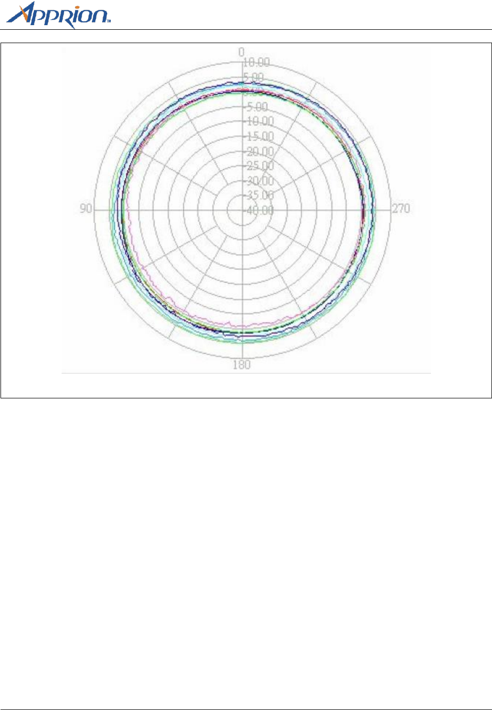
Vertical H-Plane
Appendix A – Approved Antennas
Page 22
Apprion Proprietary & Confidential
Horizontal E-Plane
Appendix A– Approved Antennas
Apprion Proprietary and Confidential
Page 23
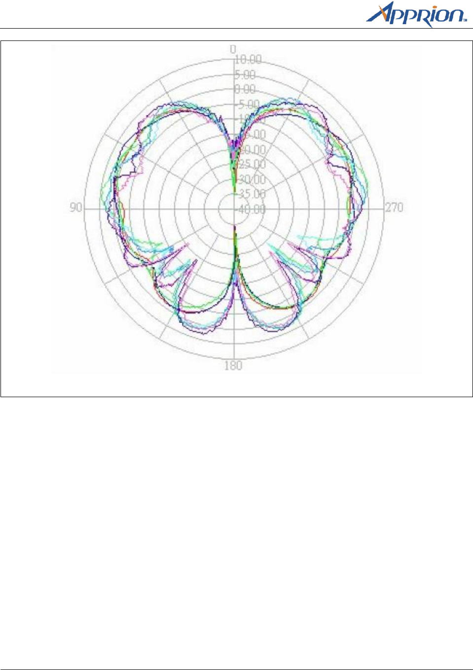
Dual Band Omni (Standard – 89-1088-000)
Typical VSWR: 2.0:1 max.
Impedance: 50 Ohm
Polarization: Vertical/Linear
Input Power: 2W
Rated Wind Velocity: 125 mph (56 m/sec)
Operating Temperature: -40° C min. to +70° max.
Connector: Type N Male
Frequency: 2400 – 2485 MHz
Gain: 7 dBi at 5150 – 5875 MHz/4.5 dBi at 2400 – 2500 MHz
Horizontal/Vertical BW: 30° at 2.4GHz, 15° at 5 GHz
Weight: 0.8 lbs. (0.4kg)
Dimensions: 27” x 0.6” (685mm x 15mm)
Appendix A – Approved Antennas
Page 24
Apprion Proprietary & Confidential
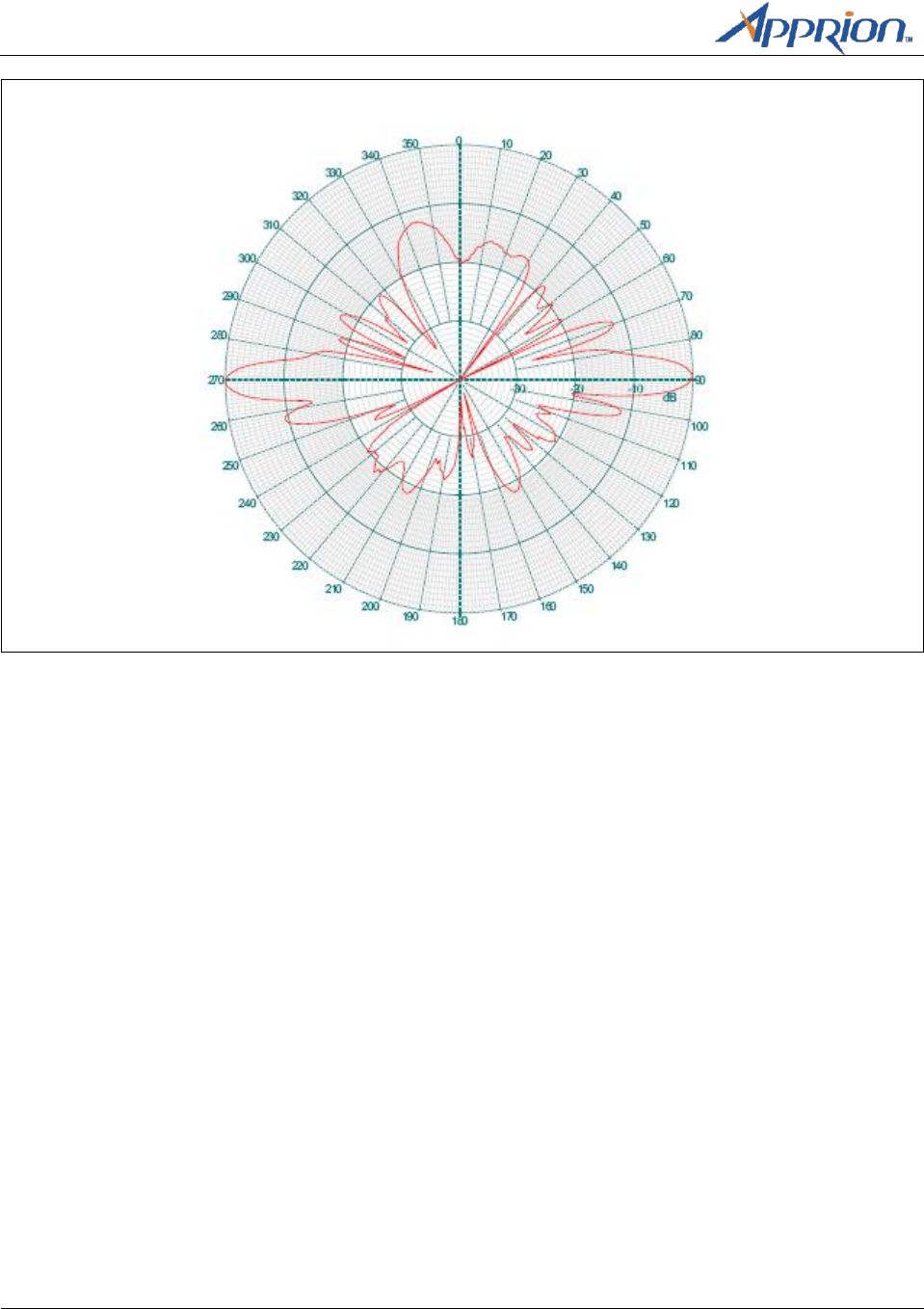
9 dBi Mesh Vertically Polarized Omni (89-1183-000)
Typical VSWR: 1.5:1
Impedance: 50 OHM
Input Power: 10 W
Rated Wind Velocity: 125 mph (56 m/sec)
Operating Temperature: -40° C min. to +70°C max.
Connector: Type N Male
Frequency: 2400 – 2485 MHz
Gain: 9dBi
Vertical BW: 14°
Weight: 0.8 lbs. (0.4kg)
Dimensions: 27” x 0.6” (690mm x 15mm)
Appendix A– Approved Antennas
Apprion Proprietary and Confidential
Page 25
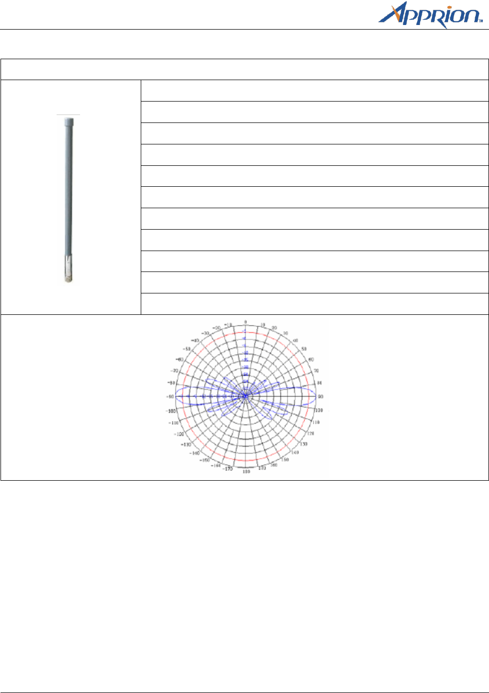
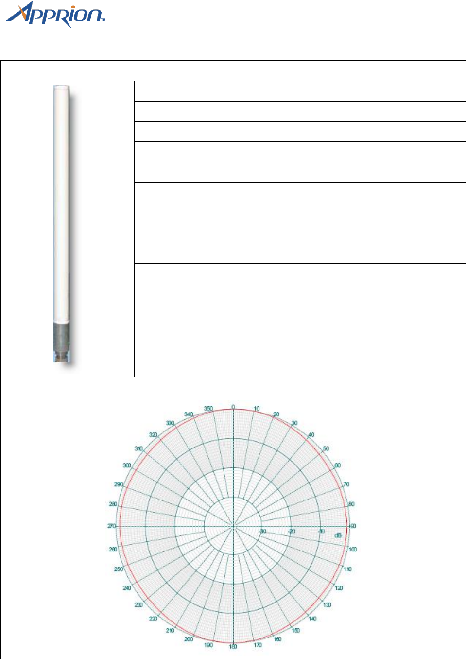
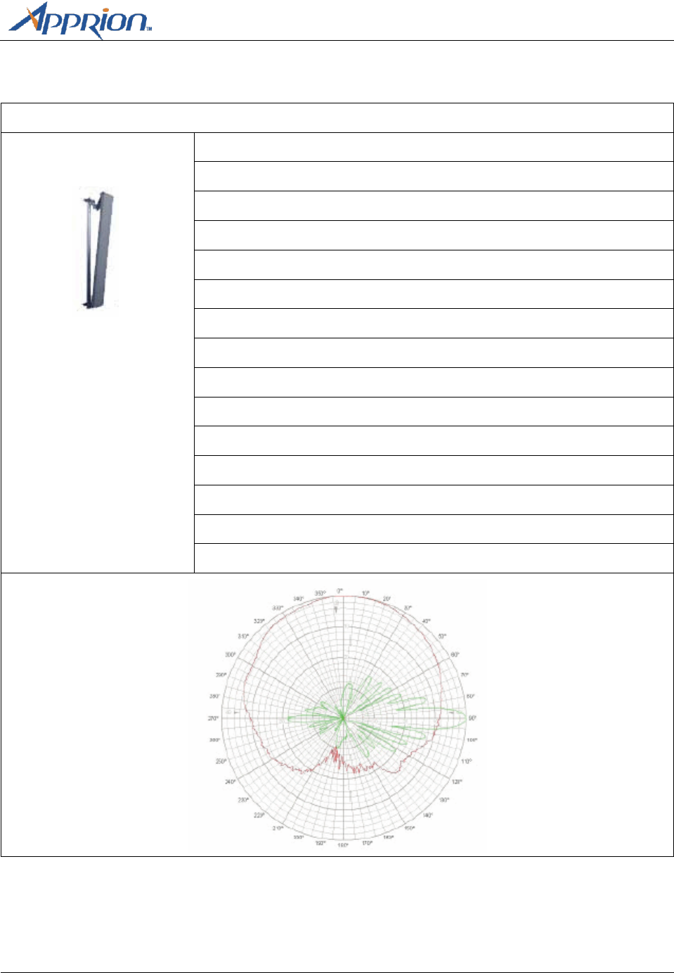
10 dBi Mesh Vertically Polarized Omni (89-1184-000)
Typical VSWR: 2.0:1
Impedance: 50 OHM
Input Power: 10W
Rated Wind Velocity: 125 mph (56 m/sec)
Operating Temperature: -30°C min. to +65°C max.
Connector: Type N Male
Frequency: 4900 – 5875 MHz
Gain: 10 dBi
3 dB Beamwidth – Elevation: 8°
3 dB Beamwidth –Azimuth : Omnidirectional
Weight: 0.4 lbs. (0.18 kg)
Dimensions: 19.6” x 1.0” (497 x 25.4mm)
H Plane
Appendix A – Approved Antennas
Page 26
Apprion Proprietary & Confidential
E Plane
Appendix A– Approved Antennas
Apprion Proprietary and Confidential
Page 27
Polarized Antennas
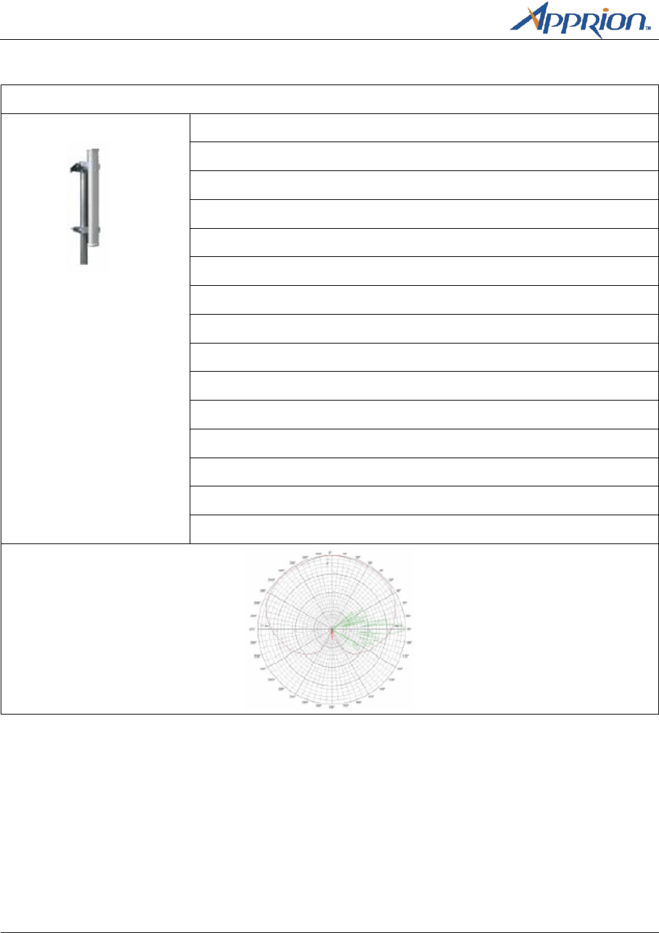
2.5 GHz 120 Degree Wide Band Vertically Polarized Sector Antenna (89-1185-000)
Typical VSWR: 1.5:1 Max.
Impedance: 50 OHM
Polarization: Vertical/Linear
Input Power: 50W
Rated Wind Velocity: 125 mph (56m/sec)
Operating Temperature: -40°C min. to +70° max.
Connector: Type N Male
Frequency: 2300 – 2700 MHz
Gain: 16 dBi
Horizontal BW: 120°
Vertical BW: 9°
Mechanical Downtilt: 30°
Weight: 6.65 lbs. (3kg)
Dimensions: 33.5 x 6.5 x 2.5” (851 x 165 x 64 mm)
Pole Diameter: 1” (25mm) to 2” (50mm)
Appendix A – Approved Antennas
Page 28
Apprion Proprietary & Confidential
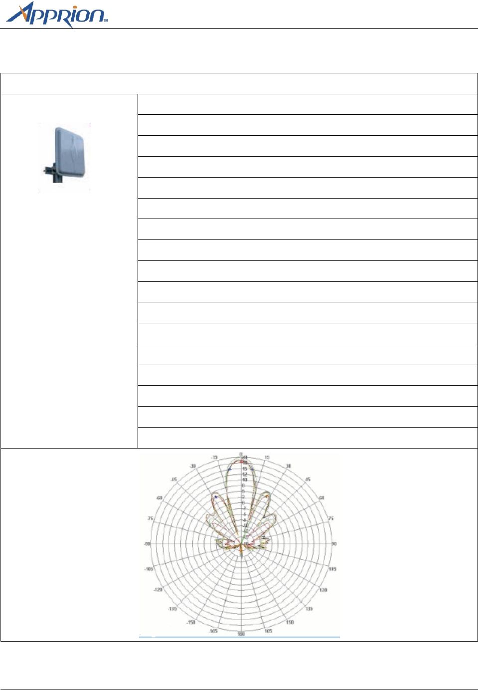
5.8 GHz 120 Degree Vertically Polarized Sector Antenna (89-1186-000)
Typical VSWR: 1.8:1 max.
Impedance: 50 OHM
Polarization: Vertical/Linear
Input Power: 10 W
Rated Wind Velocity: 125 mph (56 m/sec)
Operating Temperature: -40°C min. to +70°C max.
Connector: Type N Male
Frequency: 5850 MHz
Gain: 16 dBi
Horizontal BW: 120°
Vertical BW: 6°
Mechanical Downtilt: 15°
Weight: 2 lbs. (1.3 kg)
Dimensions: 24.6 x 2.7 x 1.7” (625 x 69 x 43 mm)
Pole Diameter: 1.5” (38mm) to 3.5” (89mm)
Appendix A– Approved Antennas
Apprion Proprietary and Confidential
Page 29
Directional Antennas
5.8 GHz Flat Panel Wide Band Antenna (89-1187-000)
Typical VSWR: 1.5:1 max.
Impedance: 50 OHM
Polarization: Vertical/Linear
Input Power: 100W
Rated Wind Velocity: 125 mph (56 m/sec)
Operating Temperature: -40°C min. to +70°C max.
Connector: Type N Male
Frequency: 5850 MHz
Gain: 19 dBi
Horizontal BW: 16°
Vertical BW: 16°
Cross Polarization: 35 dB
Front to Back: 30 dB
Bracket Tilt: 45°
Weight: 17.6 oz. (0.5 kg)
Dimensions: 7.5 x 7.5 x 0.8” (190 x 190 x 20 mm)
Pole Diameter: 1” (25mm) to 2.5” (64mm)

Appendix B – IONizer Specifications
Apprion Proprietary and Confidential
Page 31
Appendix B
IONizer 4000 Specifications
Specifications
This appendix lists the IONizer hardware specifications.
Platform
Specifications
Custom Intel XScale-IXDP465
533 MHz with DDR1-266 SDRAM
128 MB RAM/64 MB Flash
On-chip Programmable Network Process Engine (NPE)
On-chip Cryptography Unit
On-chip MII 10/100 Ethernet MACs
On-chip IEEE 1588 Hardware Assist
IEEE 802.11 a/b/g mini-PCI Modules (Typical)
Expansion (12C/SSP/2xHSS/2x921K UARTs/USB2)
Mechanical Size:
IONizer 4000 Series
11.00 inches (279.4mm) x 11.00 inches (279.4mm) x 4.00 inches (101.6mm)
Weight:
IONizer 4000 Series
6 lbs. (2.7 kg) 8 lbs. (3.6 kg shipping weight)
Housing:
IONizer 4000 Series
NEMA Type 4X (IP67) Rated Aluminum Chassis
Paint: Urethane Powder Coat
Silicone Rubber Gasket
Operating
Temperature Range:
IONizer 4000 Series:
-30C to 60C
Power
Specifications:
48 VDC PoE or 24V power connection
Maximum Power: 24W

Appendix B – IONizer Specifications
Page 32
Apprion Proprietary & Confidential
Safety Certifications:
CSAus Listed to UL60950-1 (with UL50 considerations for outdoor use)
cCSA Certified to CSA C22.2 No. 60950-1 (with CSA C22.2 No. 94 considerations
for outdoor use)
TUV Mark to EN60950-1 (with IEC60950-22 considerations for outdoor use), and
Low Voltage Directive (LVD) under CE Mark
Radio Certifications:
FCC U-NII (Part 15)
EN 300 328-2 (w/R&TTE Article 3.2 consideration)
EN 301 893 (w/R&TTE Article 3.2 consideration)
EN 301 489 (w/R&TTE Article 3.2 consideration)
European Union
Directive Info:
EC Declaration of Conformity for all European directives for this product can be
found on the Apprion website at www.apprion.com. A hard copy may be
obtained by contacting your local sales representative.