Appro Technology NVR-2028 Wireless Network Video Recorder User Manual Manual
Appro Technology Inc Wireless Network Video Recorder Manual
Users Manual

1
SAFETY PRECAUTIONS
All the following safety and operational instructions for the prevention of harm or damage to the
operator and other persons should be read before the unit is operated.
WARNING
To reduce the risk of fire or electric shock, do not expose this appliance to rain or moisture.
Do not block ventilation openings.
Do not place anything on top of the unit that might spill or fall into it.
Do not attempt to service this unit yourself as opening or removing covers may expose you to
dangerous voltage or other hazards. Please refer all servicing to qualified service personnel.
Do not use liquid cleaners or aerosols for cleaning.
This installation should be by a qualified service person and should conform to all local codes.
To prevent fire or electric shock, do not overload wall outlets or extension cord.
This unit must be grounded to reduce the risk of electric shock hazard.
CAUTION
Danger of explosion if the Lithium battery (RTC Battery) is incorrectly replaced.
Danger of explosion if battery is incorrectly replaced. Replace only with the same or equivalen
t
type recommended by the manufacturer. Dispose of used batteries according to the
manufacturer’s instructions.
Risk of explosion if replaced by an incorrect type. Dispose of used batteries according to the
instructions.
FCC B
This device complies with Part 15 of the FCC Rules. Operation is subject to the following two
conditions: (1) This device may not cause harmful interference, and (2) this device must accept
any interference received, including interference that may cause undesired operation.
NOTE: This equipment has been tested and found to comply with the limits for a Class B digital
device, pursuant to part 15 of the FCC Rules. These limits are designed to provide reasonable
protection against harmful interference in a residential installation. This equipment generates, uses
and can radiate radio frequency energy and, if not installed and used in accordance with the
instructions, may cause harmful interference to radio communications. However, there is no
guarantee that interference will not occur in a particular installation. If this equipment does cause
harmful interference to radio or television reception, which can be determined by turning the
equipment off and on, the user is encouraged to try to correct the interference by one or more o
f
the following measures:
Reorient or relocate the receiving antenna.
Increase the separation between the equipment and receiver.
Connect the equipment into an outlet on a circuit different from that to which the receiver is
connected.
Consult the dealer or an experienced radio/TV technician for help.
IMPORTANT NOTE:
FCC Radiation Exposure Statement:
This equipment complies with FCC radiation exposure limits set forth for an uncontrolled
environment. This equipment should be installed and operated with minimum distance 20cm
between the radiator & your body.
This transmitter must not be co-located or operating in conjunction with any other antenna o
r
transmitter.
Notice:
1. A Unshielded-type power cord is required in order to meet FCC emission limits and also
to prevent interference to the nearby radio and television reception. It is essential tha
t
only the supplied power cord by used.
2. Use only shielded cables to connect I/O devices to this equipment.
3. Changes or modifications not expressly approved by the party responsible fo
r
compliance could void the user’s authority to operate the equipment.
2
Table Of Contents
1. PRODUCT FEATURES .................................................................................................. 4
1.1 Product Introduction ..................................................................................................................4
1.2 Product Features........................................................................................................................4
2. DESCRIPTION OF THE FRONT/REAR VIEW............................................................... 6
2.1 Front View ..................................................................................................................................6
2.2 Rear View ...................................................................................................................................9
2.3 ALARM In/Out .........................................................................................................................10
3. INSTALLATION ............................................................................................................ 11
3.1 Basic Connection ..................................................................................................................... 11
3.2 Hard-Disk Drive Installation ...................................................................................................13
3.3 System Information ..................................................................................................................14
3.4 Updating System Software .......................................................................................................15
4. BASIC OPERATIONS .................................................................................................. 16
4.1 Configuring Recording Settings...............................................................................................16
4.2 Recording Operations ..............................................................................................................17
4.3 Playback Operations................................................................................................................24
4.4 Search Operations....................................................................................................................26
4.5 Backup Operations...................................................................................................................29
4.6 Key Lock Operation .................................................................................................................32
5. MENU SETUP .............................................................................................................. 33
5.1 LAN CAMERA SETTING.........................................................................................................34
5.2 REC SETTING .........................................................................................................................40
5.3 CLOCK / TIMER / SEQ SETTING ..........................................................................................41
5.4 ALARM SETTING ....................................................................................................................42
5.5 COMMUNICATION ................................................................................................................43
5.6 DISK SETTING........................................................................................................................49
5.7 SYSTEM SETTING...................................................................................................................50
6. IDE HARD DISK INSTALLATION ................................................................................ 53
3
6.1 Built-in hard disk......................................................................................................................53
6.2 Mobile Rack .............................................................................................................................54
7. O.S.D MESSAGE ......................................................................................................... 57
8. INDEX TABLE .............................................................................................................. 58
9. WIRELESS NETWORK CONFIGURATION................................................................. 59
9.1 Configure Your NVR-2028 Network Settings ...........................................................................59
9.2 TCP/IP Communication Software............................................................................................61
9.3 TCP/IP installation ..................................................................................................................62
9.4 TCP/IP Configuration setting ..................................................................................................62
9.5 Connection Testing...................................................................................................................63
10. NETWORK VIEWER AND IMAGE VIEWER.............................................................. 65
10.1 The Network Viewer ...............................................................................................................65
10.2 The Image Viewer...................................................................................................................75
11. MICROSOFT INTERNET EXPLORER....................................................................... 76
11.1 Connecting the NVR ...............................................................................................................76
11.2 Change LANCAM SETUP Setting..........................................................................................79
11.3 Change Record / Alarm Setting..............................................................................................80
11.4 Change Schedule Setting........................................................................................................81
11.5 Change Wireless Setting .........................................................................................................82
12. SPECIFICATIONS ...................................................................................................... 83
APPENDIX 1. –SCANIP................................................................................................... 84
APPENDIX 2. –RS-232 PROTOCOL ............................................................................... 87
1. Setup...........................................................................................................................................87
2. Communication Protocol ...........................................................................................................87
3. Command Types .........................................................................................................................88

4
1. PRODUCT FEATURES
1.1 Product Introduction
The WIRELESS NVR-2028 is a storage media of digital video image, which uses hard disk drives
instead of NAS devices to store video. This wireless storage media provides the user with the power
of remote control of the Internet. It’s an extremely stable and reliable device because it is a
stand-alone system. Its local operations are very similar to the DVR’s interface; hence if the user is
familiar with the DVR s/he will find this media to be most convenient. You don’t need to design any
analog lines yourself, just use the current existing wireless network function since the device is a
digital one. Again, where the NVR-2028 is an active device, it automatically, instantly and directly
detects all events without having to detour via a LAN Camera.
Additionally, with the NVR-2028 you don’t have to rely on a PC to save any images, because this
device has done so already, being the best possible storage media for the LAN Camera.
The device additionally hosts a wireless access point (AP), so you can transmit data without a
connecting cable. If, for example, you don’t want to use a connecting cable in an old building that is
within your surveillance system, you can use the wireless NVR-2028 instead. The same applies
equally to other sites you’re covering.
The wireless NVR-2028 also has the NAT function to enable direct access to the Internet. Inside the
device is a Router, so you don’t need to buy one as well.
1.2 Product Features
* Wireless access, complies with IEEE 802.11g/b.
* Digital recorder for the LAN Camera.
* Maximum link-up of 8 LAN Cameras.
* Zoom in/out available for every LAN Camera.
* Compression method: MJPEG.
* Maximum 2 hard-disk drive capability. (One removable)
* Hard-disk drive hot-swapping capability.
* Pre-alarm image recording.
* Capable of backup with various known FTP servers.
* Time-lapse and real-time recording.
* Refresh rate up to 30 IPS (25 IPS for PAL).
* Alarm I/O.
* Image quality selectable at 5 different levels for recording.
* Event/Timer/Alarm recording mode.
* Quick search by time, alarm, event, and recording list.
* Fast and slow playback of recorded video at various speeds.
* Single-picture playback.
* On-screen setup menu, title and system timer.
5
* Password protection.
* Motion detection: the user can select the range and 5 levels of sensitivity of detection.
* Automatic search of all available LAN cameras within the Ethernet.
* Disk-full warning and operation status LEDs.
* RS-232 communication port.
* Remote control via RS-232 and Ethernet ports
* Quick recovery after power interruptions .
* High stability and reliability.
* Operation-status record log.
* Distribution of live and recorded images throughout the TCP/IP network environment.
* Powerful PC software.
* Web browser: IE.
* Audio function included.
* Built-in SD card slot for copying images to an SD card.
* Supports the DHCP protocol.
* Optional 10DB corner antenna.
6
2. DESCRIPTION OF THE FRONT/REAR VIEW
2.1 Front View
Power Display
Save
Enter
Setup
PLAY STOP
REC
FWDREV
PAUSE
A-recSearch
T-rec
POWERDISK
1 3 4 5 6
7 8 9 10 11 14 13 12 15 16 17 18 19 20 21 22
223 24
Shift
Seq.
CH1 CH2 CH3 CH4 48
CH5 CH6 CH7 CH8
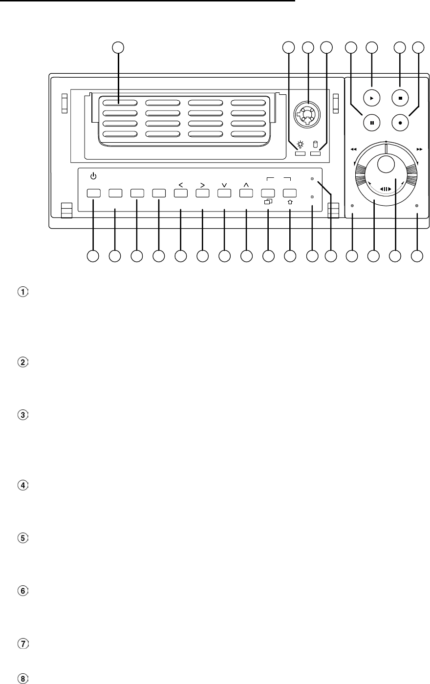
Hard-disk drive compartment:
The compartment allows you to install a hard disk drive mostly for backup purposes. Make sure the
drive is well secured with the mounting screws in the mobile rack before you put the rack into the
compartment. And remember to turn on the power of the compartment by locking it.
Hard disk compartment lock:
The key lock secures a hard disk in place. Unlock the compartment before you remove the hard
disk from the slot without turning off the device.
PAUSE button:
In a playback display, press this to freeze the display. During the freeze, press to display one
frame/field of a picture at a time in the forward direction. (A green light signals in the PAUSE
mode.)
PLAY button:
Press to play back a recorded video from the hard disk. (there is a green light signaling in the
PLAY mode.)
STOP button:
Press to stop playing back a recorded video or recording video into a hard disk. (A green light
comes on in the STOP mode.)
REC button:
Push to start recording video into a hard disk while in the live display mode. (A red light signals in
the REC mode.)
POWER button:
Press this button for at least 3 seconds to power off. Press again to activate the device.
DISPLAY button:
Press to show the system operation status on the screen.

7
In the LANCAM SETTING mode, use these buttons to display the desired LAN Camera image on the
screen.
Setup/Save button:
Press this to enter the setup menu. Press again to exit the setup mode.
In the SD card backup mode, press to save the desired still image to the SD card.
Search button:
Press to enter the search mode to access recorded video.
In the LANCAM SETTING mode, use these buttons to search for a selected LAN Camera in the
LAN.
Left / Right (CH1-CH5 / CH2-CH6 ) buttons:
In the setup menu/ search mode, press these two buttons to highlight desired items in the menu
setup mode.
In the live mode, press or buttons to select channel 1 or 2 respectively to get a full-screen
display. In order to display channel 5 or 6, please press Shift button while pushing or
buttons respectively to see the selected channel.
In the play mode, press or buttons to see channel 1 or 2 respectively, the first time as a
zoom-in, small-screen display, the next time as a full-screen display. Similarly, in order to display
channel 5 or 6 in the play mode, press Shift button while pushing or buttons respectively
to see the selected channel, first as a zoom-in, small-screen display, and next in a full-screen view.
Up / Down ( CH4-CH8 / CH3-CH7 )buttons:
In the setup menu/ search mode, press these two buttons to select the desired contents for
programming in the setup menu mode.
In the live mode, press or buttons to select channel 4 or 3 respectively to get a full-screen
display. In order to display channel 8 or 7, please press the Shift button while pushing or
buttons respectively to see the selected channel.
In the play mode, press or buttons to see channel 4 or 3 respectively, first as a zoom-in,
small-screen display, next as a full-screen display. Similarly, in order to display channel 8 or 7 in
the play mode, press the Shift button while pushing or buttons respectively to see the
selected channel, first as a zoom-in, small-screen display, and next in a full-screen view.
Enter Button:
Press to enter a selected item and save the setting in the menu setup mode.
In the live or play mode, this button enables the user to access the multiple-channel screen display.
Pressing this button repeatedly will enable a sequential display in the following order: first, a
quad-mode display of channels 1-4, and then, 5-8, and a multiple-channel display of channels 1-8,
in succession.
Shift button:
Press the Shift button while pushing either the Left / Right buttons, or the Up / Down buttons, to
see any corresponding channel between channels 5-8.
Press the Shift and Enter buttons simultaneously for a sequential display in the exact same order
given above. (please refer to the “NOTE” given below)
T-rec Indicator:

8
This indicator of the timer recording mode lights up to signal the scheduled record setting is on.
A-rec Indicator:
This indicator of the alarm recording mode lights up to indicate the alarm record setting is on.
DISK Indicator:
The indicator shows the operation status of the unit’s hard-disk drives. The green light indicates the
hard-disk drive is storing or retrieving data. The red light signals the hard-disk drive is filling up. The
orange light indicates the hard-disk is retrieving at disk-full status.
Shuttle Ring:
The shuttle can be moved forward and backward for playback in either direction. Turn it left to play
a recorded video in the reverse direction at faster or slower speeds than the recorded speed. Turn
it right to play a recorded video in the forward direction at faster or slower speeds than the
recorded speed.
Jog Dial:
This dial can act in both a forward and a backward direction, as well as step by step. Turn it left to
play a recorded video in the reverse direction. Turn it right to play a recorded video in the forward
direction.
POWER Indicator:
Indicates the power status of the unit. The green light indicates the hard disk drive is activating. The
orange light signals the hard disk drive is ready to be turn on.
Mobile Rack Power LED:
Indicates the power status of the Mobile Rack. The green light indicates the Mobile Rack is
activating.
Mobile Rack HDD LED:
Indicates the HDD status of the Mobile Rack. The orange light indicates the HDD is storing or
retrieving data.
NOTE: Press “ Enter ” and “ Shift ” simultaneously in order to view all the channels, one by
one, in sequential single-channel succession, followed by an 8-channel display, a
quad-mode display of channels 1-4, and channels 5-8, and then a multiple-channel
viewing, after which you have this exact same sequential order of display indefinitely.
9
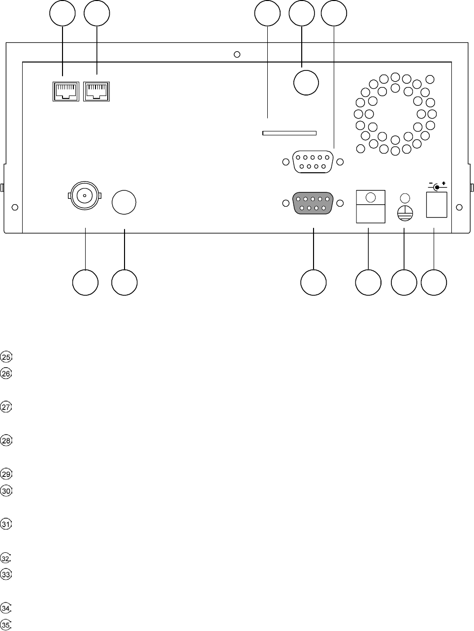
2.2 Rear View
SD Card
RS-232
ALARM DC12V
MONITOR AUDIO
ANT
I/O
25263534 27
28 29 30 31 32 33
WAN LAN
ANTENNA: This is a standard wireless access which complies with IEEE 802.11g/b.
SD CARD Slot: This is used for system software updating and the archiving/accessing of critical
images.
RS-232 Port: The RS-232 communication port functions as a connector to an external control device.
Please refer to APPENDIX 2 for more details.
MONITOR Connector: The connector provides the unit’s composite video live signal if connected to a
display device.
AUDIO OUT: This provides the unit’s audio signal to a speaker.
ALARM I/O: This is a 9-PIN D-SUB connector including GROUND, ALARM OUT, DISK FULL, and
RECORD IN for connecting with external devices. Please refer to the next section for details.
Wire Catch: The wire catch secures the power cord and keeps it in place (so that it does not droop or
hang loosely).
Ground Screw’s: The ground screw is for chassis terminal.
Plug Inlet: The inlet connects to an external power supply. Connect 12 V DC UL Listed Class 2 Power
Supply.
WAN PORT: The WAN port is linked with the DSL/Cable modem’s cable to the Internet.
LAN PORT: The LAN port connects you to the local network.
10
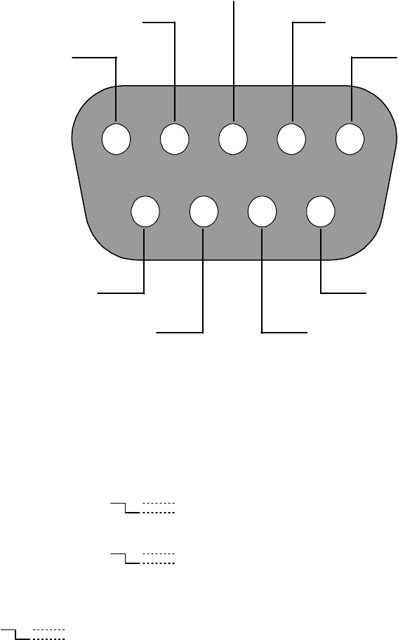
2.3 ALARM In/Out
ALARM OUT
RECORD IN GROUND
DISK FULL
NO CONNECTION
NO CONNECTION
NO CONNECTION
NO CONNECTION
NO CONNECTION
12345
6789
THE REAR VIEW
1. GND: Ground Contact.
2. ALARM OUT (OUTPUT): This is an alarm output trigger. Connect this to external devices such as
buzzers or lights. (
5V
0V(Active) )
3. DISK FULL (OUTPUT): This is a disk full output trigger. Connect this to external devices such as
buzzers or lights. (
5V
0V(Active) )
4. NO CONNECTION
5. RECORD IN (INPUT): This pin connects to a record trigger device for starting a record.
(
5V
0V(Active) )
6. NO CONNECTION
7. NO CONNECTION
8. NO CONNECTION
9. NO CONNECTION
11
3. INSTALLATION
3.1 Basic Connection
Please follow the instructions below to connect your WIRELESS NVR-2028 to a LANCAM or a
computer and to choose a mode for connections.
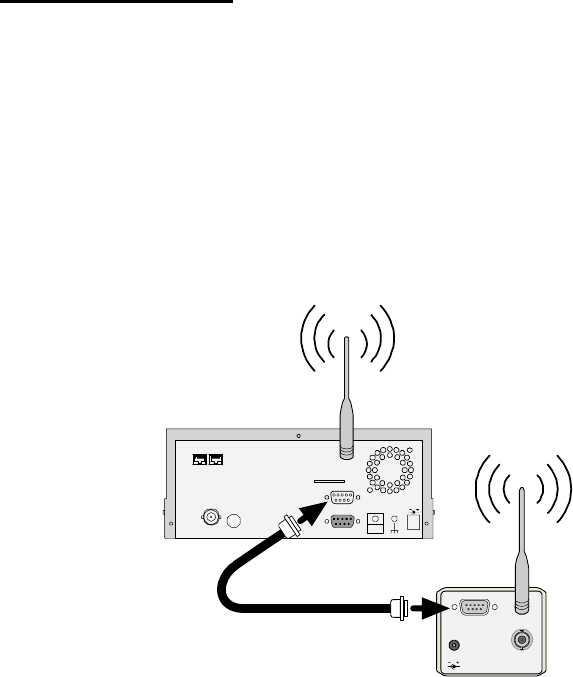
3.1.1 Use an RS-232 cable to install a wireless setting in a LANCAM
Use an RS-232 cable to connect a wireless LANCAM.
I/O
DC 5V
ANT
VIDEO
SD Card
RS-232
ALARM
DC12V
AUDIOMONITOR
ANT
I/O
NVR
wireless Lancam
RS-232 cable
WAN LAN
1. Set up all components to both the NVR and LANCAM.
(Screw up the antenna to both the NVR and LANCAM. Screw up the lens on every LANCAM.)
2. Connect the Monitor to the NVR with a BNC cable.
3. Power on the NVR: plug the NVR power cord into the outlet.
4. Turn on every LANCAM: plug every LANCAM power cord into the outlet. Make sure the NVR is
turned on before this procedure.
5. Register LANCAM to the NVR:
i. Connect the NVR and one of the LANCAMs with the RS-232 cable.
ii. Press the Setup button to enter the "MAIN MENU" page.
iii. Select the item titled “COMMUNICATION” and press the Enter button to access the
"COMM. SETTING" page.
iv. Select the item termed "WIRELESS" and push Enter twice to access the "WIRELESS
SETTING" page.
v. Choose the item labeled "OPERATION" and press Enter twice to go to the
"OPERATIONAL SETTING" page.
vi. Select the item titled "ESSID" and push "Enter" twice to get into the "ESSID SETTING"
page.
vii. Give "ESSID" your local wireless network name, and use the "<", ">", "^" and "v" buttons
to change the existing letters to your network name.
viii. Press Enter, select "OK" and go to the "WIRELESS PAGE".
ix. Push Enter to access the "WIRELESS SETTING" page and go to the item termed
"LANCAM SETUP".
x. Press Enter, choose "RS-232" and push Enter again, upon which the terms "Waiting"
and "SETUP OK" will flash on at the bottom of the screen.
12
xi. Push the Setup button to save the setup data.
xii. When the words "WAITING" flash on and off at the bottom of the screen, if the screen
goes blank, you can press the "Power" button to close the device and press it again to
resume its operation.
6. Go to the IP/ACCOUNT option on the LANCAM SETUP page in the NVR setup menu. Choose
any channel between channels 1 to 8 to set up the LANCAM IP address. Push the Search
button to find all LANCAM IP addresses and push the Enter button to choose one of them to
set the channel. Repeat step 6 to set each LANCAM IP address.
NOTE: You need to use an RS-232 cable enclosed in our package and not any other cable,
or else an error may happen.
NOTE: Once the LANCAM power cord is plugged into the outlet, it will scan the AP or NVR
device automatically and obtain an IP address from a DHCP server. This action will
continue until a DHCP server is found. If the LANCAM cannot find it after two minutes,
its IP address will change to static IP mode as 192. 168. 1. 168. The user can push the
DHCP DIP switch on the side of the LANCAM down and up once to reset the static IP
to dynamic IP (DHCP client).
NOTE: If the DHCP server of the NVR-2028 is activated, the default NVR IP address is set as
192. 168. 1. 205.
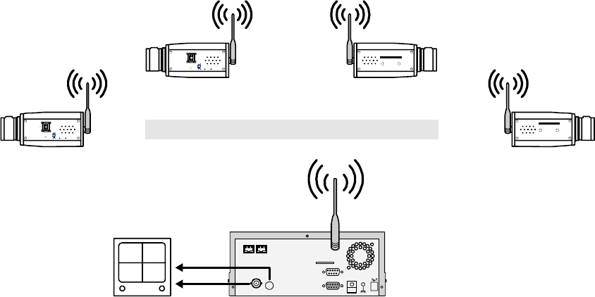
3.1.2 The Wireless Network Structure of the NVR and Its LANCAMs
The illustration below shows the wireless network of a WIRELESS NVR-2028 device connected with its
LANCAM client units, whose maximum number is eight.
SD Card
RS-232
ALARM DC12V
AUDIOMONITOR
ANT
I/O
Audio in
Video in
Monitor NVR
(UP TO 8 WIRELESS LANCAMS CONNECTION)
wireless Lancam
IRIS 1. AES
2. DC IRIS
3. DHCP
4. STATIC IP
ALC
POWER LAN
wireless Lancam
IRIS 1. AES
2. DC IRIS
3. DHCP
4. STATIC IP
ALC
POWER LAN
wireless Lancam
SD card
wireless Lancam
SD card
WAN LAN

13
3.2 Hard-Disk Drive Installation
The WIRELESS NVR-2028 is equipped with two compartments of hard disk drive. The unit usually
comes with one hard-disk drive installed in the compartment HD1, which is default-configured as a
master. If you need a second hard-disk drive to be installed in the compartment HD2 (Mobile), please
contact your distributors or installers for specific instructions on how to install it. Please don’t serve
yourself before consulting your installers. If there is only one hard-disk drive in the mobile compartment,
please set the HD2 USAGE option to REC (Please refer to section 5.6) before proceeding with the
recording function. The jumper-settings arrangement of installed hard-disk drives for the system (Table
3.2 A.) is shown in the tables below.
Table 3.2 A. The jumper settings of hard disk drives in the system
Location Jumper
IDE 1 Compartment HD 1 Master (Default)
IDE 2 Compartment HD 2 Master
Table 3.2 B. Compatible hard-disk drives
Manufacturer Model Capacity Rotation
WD800AB 80GB 5400 RPM
WD1200AB 120GB 5400 RPM
WD800BB 80GB 7200 RPM
WD1200BB 120GB 7200 RPM
WD1800BB 180GB 7200 RPM
WD2000BB 200GB 7200 RPM
Western Digital
WD2500JB 250GB 7200 RPM
ST380020A/P 80GB 5400 RPM
ST340810A/P 40GB 5400 RPM
ST320014A 20GB 5400 RPM
ST340015A 40GB 5400 RPM
ST380012ACE 80GB 5400 RPM
Seagate
ST3120025ACE 120GB 5400 RPM
4A160J0-1A 160GB 5400 RPM
4R080L0-1 80GB 5400 RPM
6Y120L0-1 120GB 7200 RPM
6Y200P0-1A 200GB 7200 RPM
Maxtor
6Y250P0-1A 250GB 7200 RPM
SV0802N 80GB 5400 RPM
SAMSUNG
SV1203N 120GB 5400 RPM
NOTE: Hard-disk drives not shown on this list have not been tested by the engineering team
and are not recommended for use with this product. For the latest updated list on the
recommended hard disk drives, please contact your dealers or distributors.

14
3.3 System Information
You can display system settings information as shown on Table 3.3 A below at any time by pressing the
Display button . The recorded video information is displayed in the playback mode. The Manual
Recording information is displayed in the live or recording mode. Each sequential push on the Display
button displays a different message detailed in the following example. By default, the unit displays
time, date, and an indicating bar of capacity status on a monitor as shown next.
Default display
Press the Display button once; the NVR will display the following sample message plus the default
display. Press the Display button again; the unit will not display any OSD message. Press the
button one more time to return to the default display.
Table 3.3 A. Description of Table 3.3 A
(CH): Channel
(LANCAM IP): LAN Camera IP address
(LIVE): The LAN Camera activated
(OFF): The LAN Camera inactivated
(19): The channel current display speed rate, 19 images/sec
():Disconnection; ():Alarm; ():login error;
():motion; ( ):Audio; ( ):Timer
(227K): The LAN Camera bandwidth
(LANCAM IP : 192 . 168 . 001 . 205): Setting of the Ethernet
communication,192.168.001.205
(DHCP:OFF): Only use manual setup IP address
(NTSC): NTSC system
(): Indicate which HDD is activated
(HD): Hard disk Compartment
(SIZE 20G): The capacity of the installed hard disk
(POS): Percentage of system; R: Recording; P: Playback
11 HR (HD1): Change per minute showing the total recording
time.
(X): Cannot operate at now
CH LANCAM IP X
1 192.168.001.250 LIVE
2 192.168.001.020 LIVE
3 192.168.001.030 - - -
4 192.168.001.040 OFF
5 192.168.001.050 OFF
6 192.168.001.060 OFF
7 192.168.001.070 OFF
8 192.168.001.080 OFF
IP : 192.168.001.205 DHCP:OFF NTSC
HD SIZE POS
1 20 G 39.5% R 11 HR (HD1)
2 39 G 0.0% P
04-09-2003 12:48:19
CAM1 CAM2
CAM3 CAM4 CAM5 CAM6
CAM7 CAM8
04-09-2003 12:48:19
15
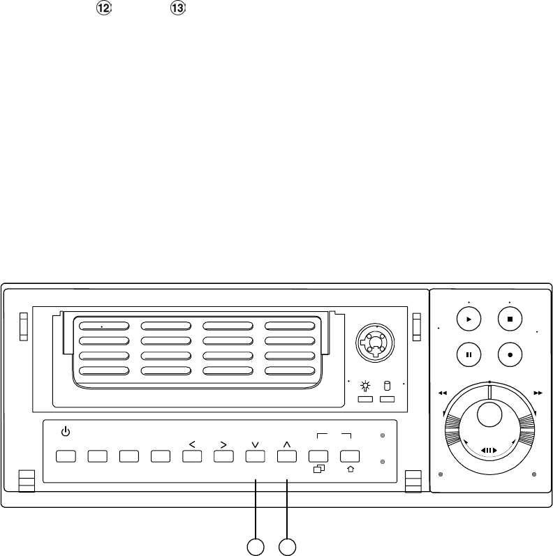
3.4 Updating System Software
If the system software of the NVR needs to be upgraded, please take the following steps to safely
update it.
Note: Before carrying out the following procedures, please ensure the SD card is working and
the file of the system software is intact
1. Create a directory named NVRVIDEO in the SD Card; if the directory is already there, move to
Step2.
2. Copy the file of MULTI.BIN to the NVRVIDEO-directory.
3. If the wireless NVR-2028 is running, please turn it off wireless NVR first.
4. Insert the SD card into the built-in SD slot of the unit.
5. Hold down the Up and Down buttons simultaneously, and then turn on the unit.
6. Keep holding down the buttons until the NVR sounds a tone and display the message “ XXXXXX
BYTES READ” Now the NVR is updating the system software, which will take approximately 60
seconds to process.
7. Restart the unit when the device sounds a tone twice and displays the messages “PROGRAMMING
END” and “ PLEASE RESTART”. The process is complete.
(If you have already followed procedures 1~5 but the unit still cannot be activated, please first check
if the SD card you are using is functioning and the file is intact. And then start procedures 1 ~ 5 all
over again.)
8. Verify the version of the system software. (Please refer to the section 5.7 VERSION option)
Power Display
Save
Enter
Setup
PLAY STOP
REC
FWDREV
PAUSE
A-recSearch
T-rec
POWERDISK
13 12
Shift
Seq.
CH1 CH2 CH3 CH4 48
CH5 CH6 CH7 CH8
Warning: Don’t interrupt the process while the unit is updating itself and don’t proceed
with an SD card containing a system software of the unit, which would cause
the unit to hang on.

16
4. BASIC OPERATIONS
This section shows you how to operate and manage the NVR when it gets in the way.
4.1 Configuring Recording Settings
Recording Time Settings (Image Resolution and Image Quality Setting)
Recording time will vary depending on the image size, quality, and the capacity of the hard-disk drives.
Generally, the NVR comes with a built-in hard-disk drive for continuous recording under most recording
conditions. The table below shows the possible recording times based on a 20GB hard-disk drive at
certain refresh rates and the corresponding image quality. With one or more hard-disk drive(s) in
operation, please calculate the recording time using the table below in accordance with your requirement.
For example, if the unit is set to record images with the HIGHEST quality at a 352 X 240 resolution,
normally a 20GB hard-disk drive will be filled in 13 hours (see the gray area in the table). If the total
capacity of 80GB hard-disk drives is in use under the same refresh rate, image resolution and image
quality, it will be filled in 52 hours (4 times the rate of a 20GB hard-disk drive).
( 352 X 240 )
Audio OFF Possible Recording Time HDD=20GB ( hour )
HIGHEST 13 19 37
HIGH 18 25 52
MEDIUM 24 32 66
LOW 29 44 81
Image
Quality
LOWEST 43 66 137
R
efresh Rate ( Image/Sec ) 30 20 10
R
EC Time Mode 2 hr 4 hr 6 hr
( 720 X 480 )
Audio OFF Possible Recording Time HDD=20GB ( hour )
HIGHEST 11 18
HIGH 13 24
MEDIUM 17 31
LOW 23 48
Image
Quality
LOWEST 39 76
R
efresh Rate ( Image/Sec ) 30 20 10
R
EC Time Mode 2 hr 4 hr 6 hr
NOTE: Recording times on the tables above are estimated. For the actual available
recording time of a recording configuration, refer to the system information of the
NVR. (Please refer to section 3.3 system information for more details.)

17
4.2 Recording Operations
This section details the way to record video into hard-disk drives. Before commencing with the recording
function, please configure the recording setting properly according to your needs.
4.2.1 Manual Recording
When the NVR is in live display mode, take the following steps to start recording:
(1) In live display, press the REC button to record video into a hard disk drive with the
corresponding programmed recording settings. The monitor should display a flashing REC
message and the REC button will light up indicating the NVR is in the recording status.
(2) Press the STOP button to stop recording any time.
(3) To access just recorded video, please refer to section 4.4 for more details.
4.2.2 Timer Recording
Timer recording provides two periods of time each day in a weekly table which programs the NVR
to turn on and off at specified times. This way the NVR will start and stop recording according to
the programmed schedule. Please take the following steps to program the scheduled recording.
(1) Press the Setup button to enter the MAIN MENU.
(2) Select the CLOCK / TIMER / SEQ and press the Enter button to enter the CLOCK /
TIMER / SEQ page.
(3) Select the TIMER-SET.
(4) Press the Enter button to enter the REC SCHEDULE table.
(5) ● You can set up by using the “<” button and the “>” button to locate the specific
day/hour/minute and use the “^” button and the “v” button to set the
day/hour/minute you wish.
● You can also set up by using the Shuttle Ring and the Jog Dial. is the equal of the “<”
button , is the equal of the “>” button , is the equal of the “^” button
and is the equal of the “v” button .
● The time is displayed in a 24-hour clock format.
(6) To activate the programmed recording schedule, set the TIMER ENABLE to ON. As the
scheduled recording is on, the red indicator of the Timer Record will be on as well. To
deactivate it, set to OFF.
(7) After scheduling is completed, press the Enter button and set OK to save the setting or
select CANCEL to leave the page without saving the settings.
(8) Press the STOP button during the scheduled recording to stop it at any time. If you wish to
continue the scheduled recording, press the REC button