Aprilaire 5000 Users Manual RP 191452
5000 to the manual ba10eafe-7d7b-4926-bea0-17979497e375
2015-02-03
: Aprilaire Aprilaire-5000-Users-Manual-467131 aprilaire-5000-users-manual-467131 aprilaire pdf
Open the PDF directly: View PDF ![]() .
.
Page Count: 8

SAFETY AND INSTALLATION MANUAL
MODEL 5000
TABLE OF CONTENTS
Safety Instructions ...........................................................................................................2
Specifications......................................................................................................................2
Components........................................................................................................................3
Installation ............................................................................................................................4
Operating Instructions....................................................................................................6
Trouble Shooting Guide................................................................................................6
ELECTRONIC AIR CLEANER
®

SAFETY INSTRUCTIONS
Read the safety and installation instructions carefully. They will help ensure a correct and
SAFE installation of the Aprilaire®Electronic Air Cleaner.
WARNING:
• 120 Volts may cause serious injury from electrical shock. Disconnect power to the furnace/air
handler before starting installation. Leave power disconnected until installation is completed.
• Arcing in electrical components may cause an explosion. Do not install unit where explosive
gasses will be present.
• Sharp edges may cause injury from cuts. Use care when cutting and handling sheet metal.
• To reduce the risk of electrical shock, this equipment has a grounding-type (three prong) plug.
This plug will fit only into a grounding-type power outlet. If the plug does not fit into the outlet,
contact qualified personnel to install the proper outlet. Do not alter this plug in any way.
• To reduce the risk of electrical shock, locate product so that the power cord can be plugged into
an electrical outlet without the use of an extension cord.
CAUTION:
• To prevent component failure, do not install the air cleaner on the warm air supply or in an
area where the temperature may exceed 149° F. This may include areas above heat exchangers
in downflow furnaces or above exhaust flues in lowboy furnace cold air returns.
• The air cleaner must be installed where the ambient air temperature remains between 32° F
and 149° F [0° C and 65° C].
• Installation must conform to all applicable codes.
• Do not install an atomizing humidifier upstream of the air cleaner. Water or mist will cause
power supply to shut down.
SPECIFICATIONS
Description The Aprilaire Electronic Air Cleaner Model 5000 is an electronically
enhanced “ElectraMedia” air cleaner.
Unit Dimensions Overall Unit – 17 3/4" x 31 1/8" x 11 1/2"
Airflow Capacity 2000 cfm maximum
Input Voltage Requirements 120V AC ± 15%, 50/60 Hz Nom., Unit equipped with a 5 ft. grounded cord
with plug.
Power Usage Less than 50 watts with high voltage active.
Shipping Weight 35 lbs.
© Research Products Corporation 2002
2
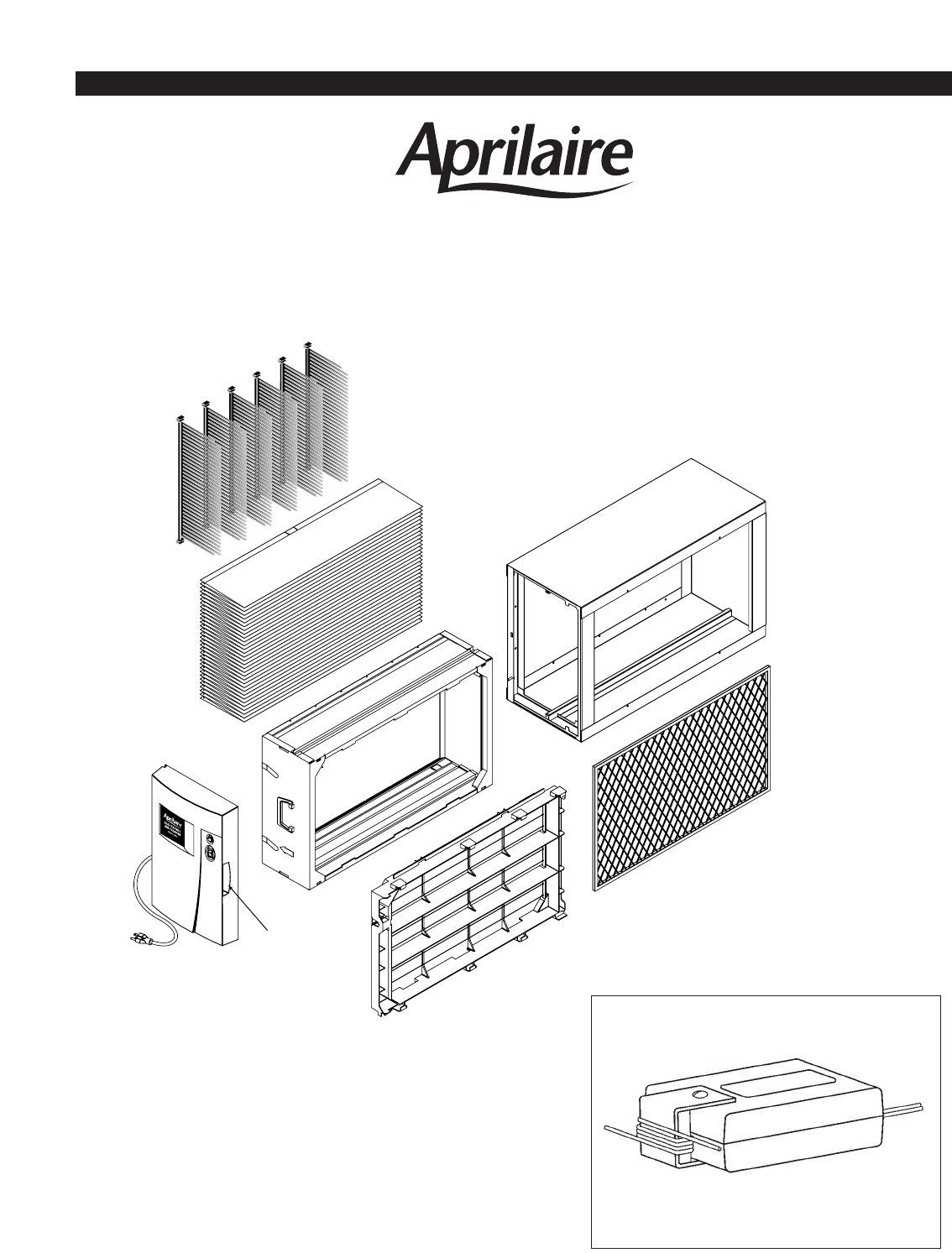
POWER PACK / DOOR ASSEMBLY IONIZER FRAME
CONTROL ELECTRODE
OUTER HOUSING
INNER HOUSING
#501
MEDIA
PLEAT SPACERS
Handle
COMPONENTS
MODEL 5000
ELECTRONIC AIR CLEANER
®
Figure 1
3
Model 51
An Aprilaire®Automatic Humidifier can be mounted upstream from the air cleaner.
CAUTION: Do not install an atomizing humidifier upstream from the air cleaner.
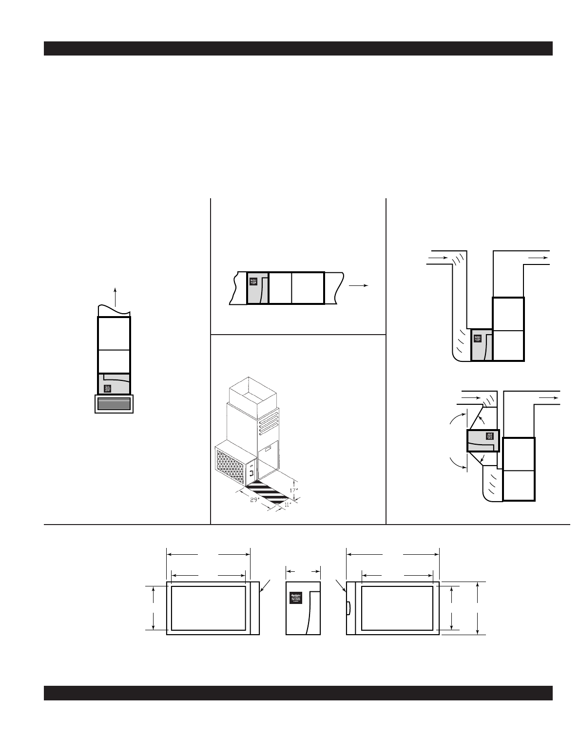
INSTALLATION
Important
Airflow
Upflow "Highboy" - Closet Installation
(Bottom Return)
Airflow
Horizontal Installation
Airflow
Upflow "Highboy" - Side Return Installations
Airflow
30° max.
45° max.
14 3/4
"
237
/8
"
281/8
"
without door
111
/2
"
door door
17 3/4
"
247
/8
"
311/8
"
with door
Outlet Side
Furnace Connection
Inlet Side
Return Duct Connection
Front
14 3/4
"
The Model 5000 Air Cleaner is designed for systems
with airflow up to 2000 cfm. If the furnace has
more than one return air inlet connection, install
one air cleaner in each.
The air cleaner can be installed horizontally, vertically,
or at an angle depending on furnace type. Figures
2, 3, and 4 show unit orientation in various types of
applications. Note airflow direction arrows on inner
assembly and outer housing.
Allow 29” clearance in front of the unit for media
replacement (see Figure 5).
If a transition or offsets are required, minimize
transition angles to reduce system pressure drop
(see Figure 4). Figure 6 shows the air cleaner
dimensions.
Figure 2
Figure 3 Figure 4
Figure 6
4
Allow Clearance for
Removal of Inner Housing
for Filter Replacement
Figure 5
Minimize Angles
Where Possible
Figure 5
APPLICATIONS WITH A HUMIDIFIER
INSTALLATION PROCEDURE
Warning: 120 Volts may cause serious injury from electrical shock.
Leave power disconnected until installation is completed.
1. Remove air cleaner power pack / door
assembly and pull inner assembly out of
the outer housing.
2. Remove media carton from the inner housing.
3. Turn off furnace/air handler.
4. On retrofit applications, remove existing filter,
discard it, and thoroughly clean the blower and
blower compartment.
5. With airflow label in proper orientation, attach
outer housing to furnace/air handler system.
Seal inlet and discharge connections with caulk
or mastic and provide support for the housing as
required (See Figure 7). See Figures 2 through 4
for typical system types.
6. Install the media using the instructions
on the media carton.
7. Check to make sure that the ionizer
frame is properly inserted into the inner
housing and that the control electrode
is inserted fully into the ionizer frame.
8. Insert the inner assembly into the outer
housing and replace the door.
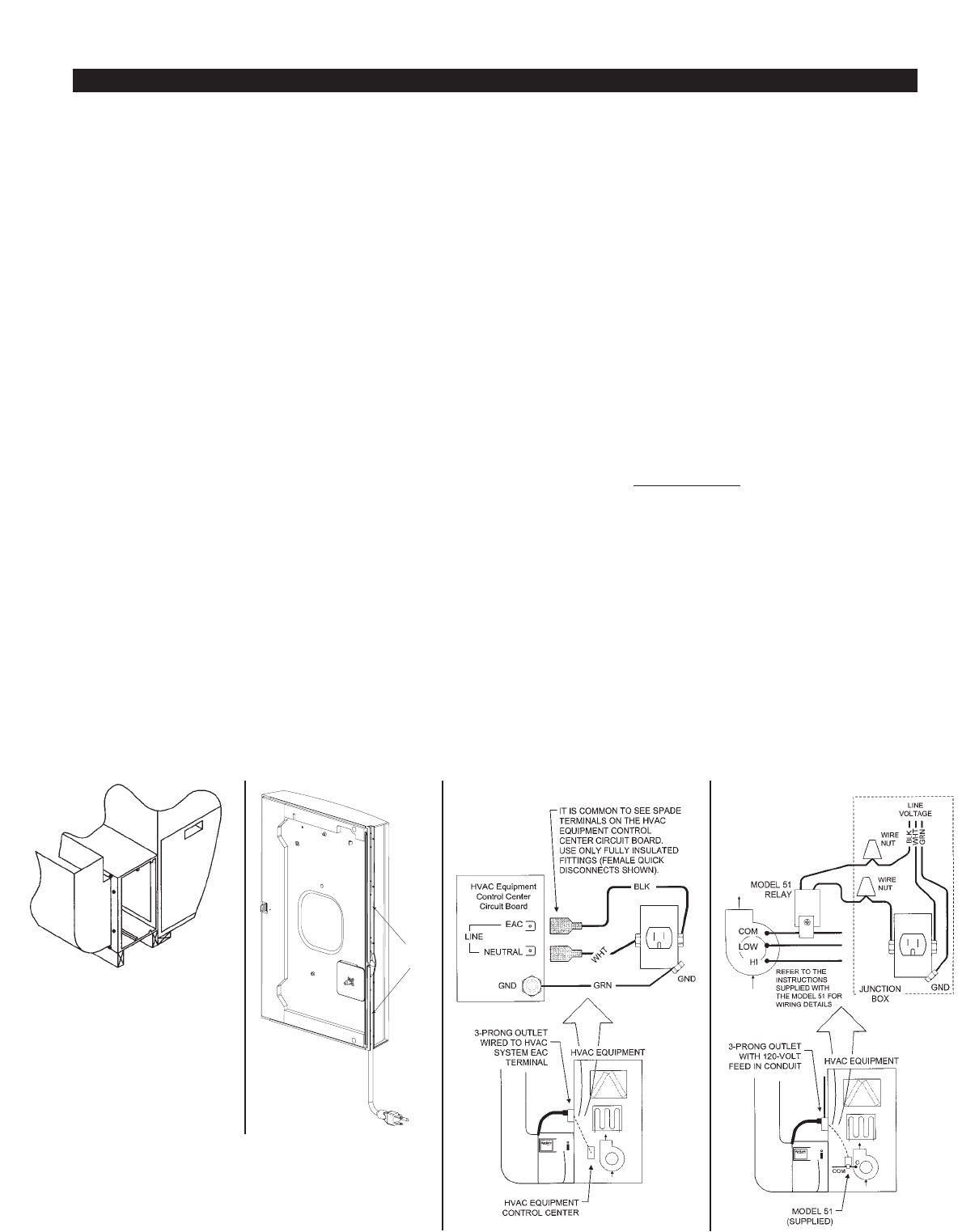
9. Press the power cord into the slot in the
side of the power pack / door assembly
so that it is directed towards the outlet.
See Figure 8.
10. Install a single outlet receptacle to the
furnace/air handler cabinet which conforms to
NEC standards as well as all applicable local
codes, using 1 of the 2 options below:
Figure 9- Use the furnace/air handler EAC
terminals to wire the outlet. Figure 10- If EAC
terminals are not available use the Model 51
(supplied) to wire the outlet and refer to the
instructions provided with the Model 51.
The outlet must only energize when the system
blower is on. IMPORTANT:Identify the outlet for
“EAC USE ONLY”
11. Return power to the furnace/air handler.
12. Plug the Aprilaire Air Cleaner power cord into
the outlet installed in step 10.
13. Check for proper operation when the furnace is
run through heating and cooling cycles.
14. Provide owner’s manual and warranty card to
homeowner after explaining operation of unit.
Power
Cord Slot
Figure 7 Figure 8 Figure 9 Figure 10
5
Support Air Cleaner to Prevent
Torque on Outer Housing.
OPERATING INSTRUCTIONS
The inner housing assembly must be installed and
the power pack / door assembly to the air cleaner
must be fully closed.
The unit should be plugged in and the power
switch on the air cleaner door turned on. There are
no other controls or settings required.
When the system blower turns on, the air cleaner
will turn on and a green light located on the air
cleaner door will turn on. After the system blower
has turned off, the green light will turn off.
TROUBLE SHOOTING GUIDE
When the air cleaner is operating
correctly and the following
conditions are met, the green
light on the door will be on:
• The air cleaner is correctly
assembled and installed.
• The power pack / door
assembly is fully closed.
• The unit is plugged into
an EAC controlled 120 VAC
outlet.
• The switch is in the ON
position.
• The furnace/air handler
blower is running.
If those conditions are met and
the green light does not come on,
the air cleaner circuit is not being
activated. If the green light blinks
at approximately one-minute
intervals, the air cleaner circuitry
is attempting to turn on, but is
quickly turning off due to either
an over-current condition or
because arcing is occurring
between components. Check
the inner assembly as follows:
1. Turn the furnace/air handler blower off.
2. Turn the air cleaner off.
3. Unplug the air cleaner.
4. Open the power pack / door assembly.
5. Remove the inner housing assembly.
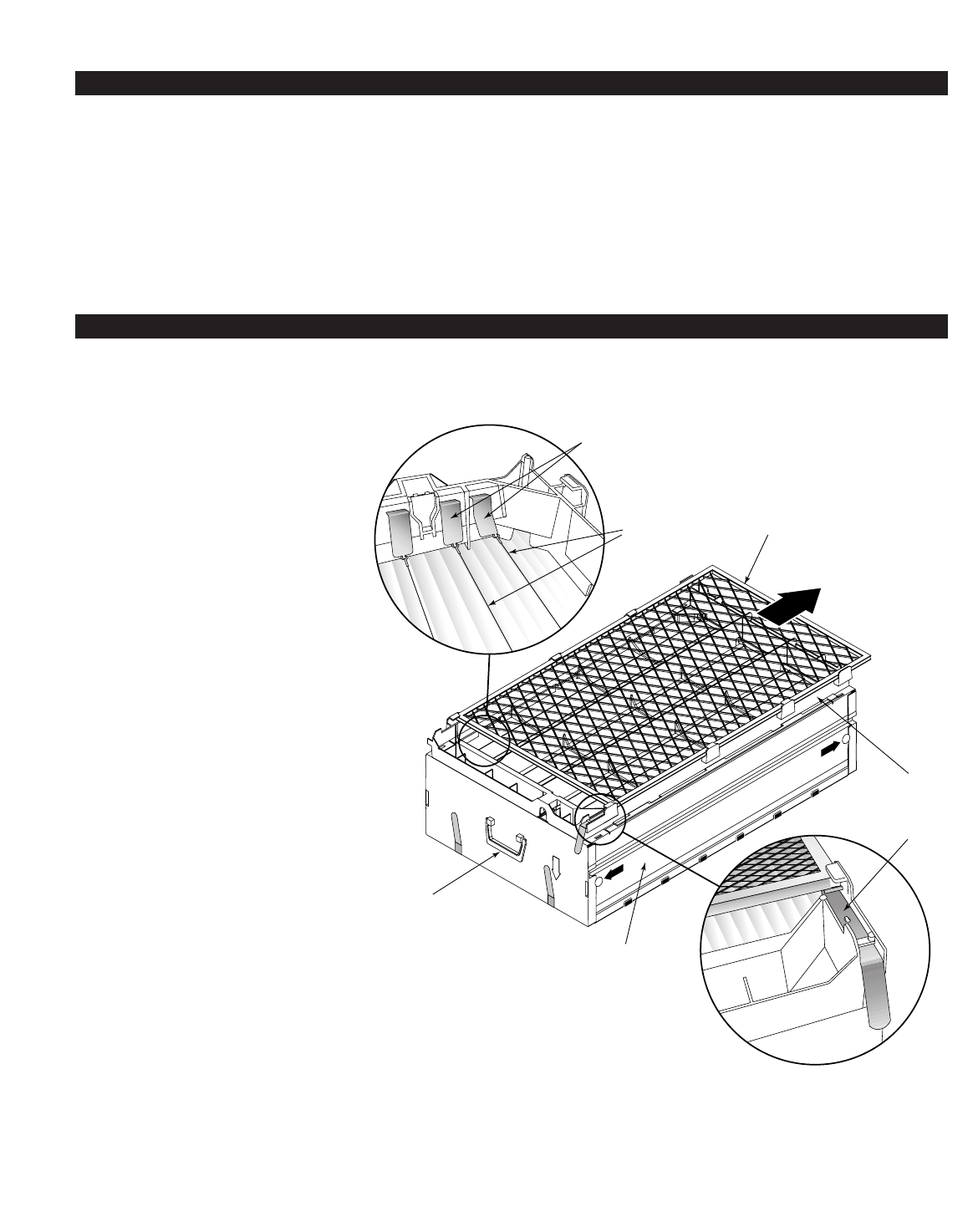
6. Inspect components to ensure the following:
a. All components must be dry.
b. The ionizer frame-grounding clip must be
in contact with the pre-filter. See Figure 11.
Figure 5
Handle
Ionizer
Wires
Inner Housing
Ionizer Frame
Grounding Clip
Control Electrode
Bus Bar
Figure 11
6
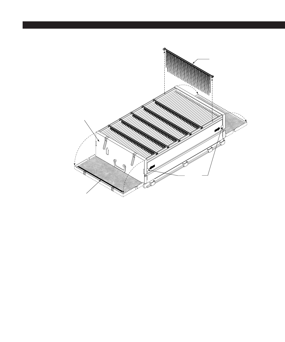
6. Inspect components to ensure the following
(continued):
c. The conductive rubber strip must be in
contact with the conductive-coated tips of
the media. See Figure 12.
d. The nine ionizing wires must be clean,
straight, and hooked onto the bus bar at
one end and the ionizer frame at the other.
See Figure 11.
e. The control electrode must be properly
inserted in the ionizer frame.
f. There must be no debris bridging the gap
between the ionizing wires and any other
component.
7. If a Model 51 is used:
a. Measure the current for the wire under the
bracket - this must be 4 amps or more.
b. Ensure the Model 51 is at least 4” away
from any transformer.
8. Re-install the inner housing assembly
and close the power pack / door assembly.
9. Plug in the unit and turn it on.
10. Turn on the furnace/air handler blower.
11. After the blower starts, check unit for proper
operation.
TROUBLE SHOOTING GUIDE (CONTINUED)
Pleat
Spacer
“PRESS
TO OPEN”
End Panel
Conductive
Rubber Strip
Figure 12
7

DP# 10004114 5.5.02
P.O. BOX 1467 • MADISON, WI 53701-1467 • Phone 608/257-8801 • FAX 608/257-4357 • Products For Better Indoor Air Quality™
