Aprilaire Thermostat 8910 Users Manual
8910 to the manual 0374423f-bce5-4dc7-ba9d-5c4cd63752e0
2015-02-03
: Aprilaire Aprilaire-Thermostat-8910-Users-Manual-467308 aprilaire-thermostat-8910-users-manual-467308 aprilaire pdf
Open the PDF directly: View PDF ![]() .
.
Page Count: 13

Home Comfort Control™
Model 8910
Thermostat installation location recommendations ...2
Thermostat mounting...........................2
Equipment control module installation location
recommendations..............................2
Equipment control module mounting ..............2
Thermostat wiring .............................3
Remote temperature sensor (optional) .............3
Equipment control module wiring .................4
Outdoor temperature sensor .....................5
Optional wireless outdoor temperature sensor ......5
Return air temperature sensor (optional) ...........6
Leaving air temperature sensor (optional) ..........6
TABLE OF CONTENTS
INSTALLATION POWER & RESET OPTIONS
SETUP & TESTING
REFERENCES
HVAC WIRING DIAGRAMS
INDOOR AIR QUALITY WIRING DIAGRAMS
Power and reset options .......................10
Equipment type selection switch (SW1) ...........11
Installer setup menu ..........................11
Change system settings........................11
HVAC installer system settings table ..........12-13
Indoor Air Quality system settings tables..........14
Air cleaning sytem settings table ..............14
Humidifier system settings table ...............14
Dehumidifier system settings table .............15
Ventilation system settings table...............16
System test menu .........................17-18
System test tables.........................18-20
Quick reference to controls & display..........21-22
Troubleshooting ...........................22-23
Error codes ..................................23
Home Comfort Control features .................23
Specifications................................24
Conventional heat/cool single transformer..........7
Conventional heat/cool two transformer ...........7
Heat pump single transformer....................8
Heat pump two transformer .....................8
Indoor Air Quality wiring with separate transformers ...9
Indoor Air Quality wiring with a single transformer.....9
Safety &
Installation
Instructions
READ AND SAVE THESE INSTRUCTIONS

2 3
INSTALLATION
THERMOSTAT INSTALLATION LOCATION RECOMMENDATIONS
EQUIPMENT CONTROL MODULE INSTALLATION LOCATION RECOMMENDATIONS
Thermostat should be mounted:
Equipment control module should be mounted:
140°F (60°C) or drop below 32°F (0°C).
Do not mount thermostat:
appliances that give off heat.
outside doors.
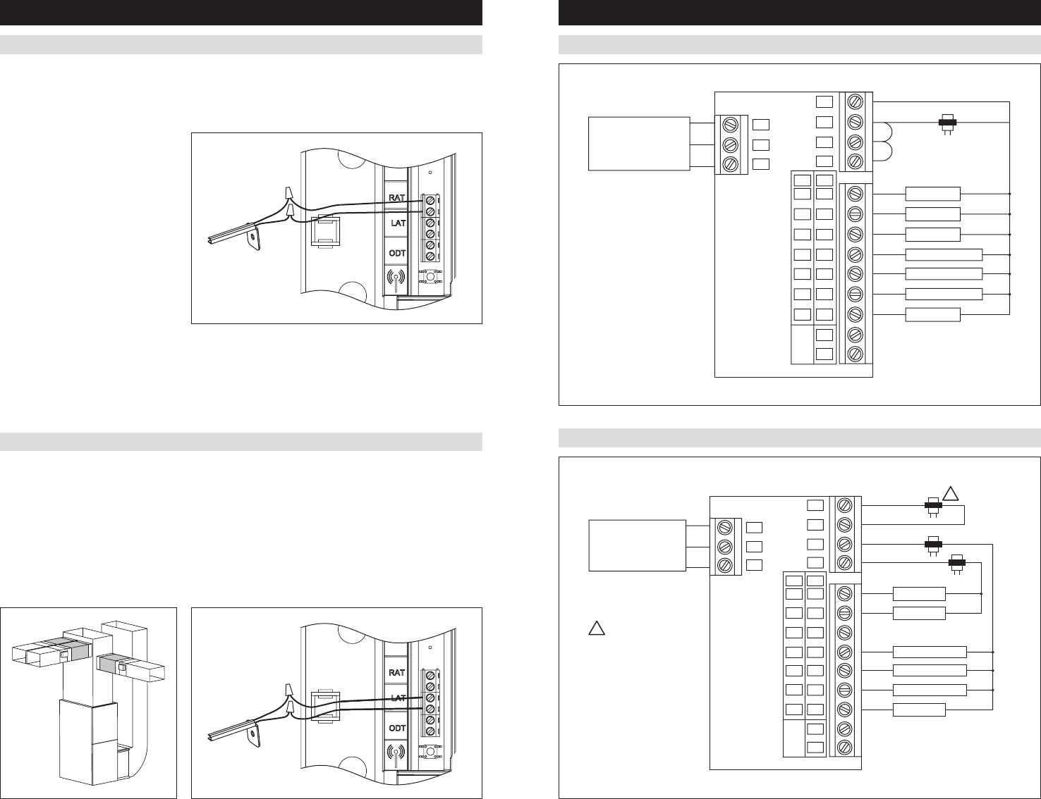
REMOTE TEMPERATURE SENSOR (OPTIONAL)
THERMOSTAT WIRING
A remote temperature sensor can be used if the thermostat is to be mounted in a concealed location. A 8051 flush
mount or 8053 surface mount remote temperature sensor can be attached to the T1 and T2 terminals and mounted
override the thermostat’s internal temperature sensor.
123T1T2
Remote temperature sensor should be
mounted:
space.
Do not mount remote sensor:
spaces.
other appliances that give off heat.
or near outside doors.
THERMOSTAT MOUNTING
EQUIPMENT CONTROL MODULE MOUNTING
1. Remove the rear mounting plate from the thermostat.
2. Pull wires through the opening on the back of the thermostat.
3. Position and level the mounting plate of the thermostat on
wall and mark the hole locations with a pencil.
6. Seal wire entry holes to prevent drafts affecting temperature
readings.
The Equipment Control Module has the following features to simplify mounting and wiring and provide for a clean
and neat installation.
be utilized. Mount the Equipment Control Module using 2 to 4 #8 screws appropriate for the mounting surface
substrate. (See Figure 2.)
to secure wires in 10 places.
Installation Steps
1. Select mounting location.
2. Pull from bottom to remove
front cover. (See Figure 1.)
3. Mount base using 2 to 4 #8
screws (field supplied).
123T1T2
INSTALLATION
Do not mount equipment control module:
ductwork. These locations can cause moisture to
condense on the equipment control module.
Wire specifications:
18-24 gauge thermostat wire
Installation notes:
and re-tighten.
1 – Connection to terminal 1 at equipment control module
2 – Connection to terminal 2 at equipment control module
3 – Connection to terminal 3 at equipment control module
T1 & T2 – Remote temperature sensor (optional)
Figure 1 Figure 2
Note:
loss of programs due to electrical discharge.

4 5
INSTALLATION INSTALLATION
EQUIPMENT CONTROL MODULE WIRING
Wire specifications:
18-24 gauge thermostat wire
Installation notes:
and re-tighten.
channels.
1 – Connection to terminal 1 at thermostat
2 – Connection to terminal 2 at thermostat
3 – Connection to terminal 3 at thermostat
RAT – Return air temperature sensor (optional)
LAT – Leaving air temperature sensor (optional)
ODT – Outdoor temperature sensor (optional)
C – 24VAC common
R – 24VAC
RC – 24VAC Cooling
RH – 24VAC Heating
W
W2
pump)
W3/B – Third stage heat (conventional)/reversing valve
(heat pump)
Y – First stage cooling (conventional)/first stage compressor
(heat pump)
Y2 – Second stage cooling (conventional)/second stage
compressor (heat pump).
Y3/0 – Third stage cooling (conventional)/reversing valve
(heat pump)
G – Fan
L – System fault indicator (heat pump only) (optional)
CEQ – 24VAC common from heat pump for system fault
indicator (optional)
HUM – Humidifier
DHno & DHcom
DHnc & DHcom
VENT – Ventilation
EAC – Electronic Air Cleaner
OUTDOOR TEMPERATURE SENSOR
OPTIONAL WIRELESS OUTDOOR TEMPERATURE SENSOR
Outdoor temperature can be measured by installing an 8052 sensor (included) to the ODT terminals and enabling the
In heat pump mode the outdoor temperature sensor can be used to efficiently utilize an air source heat pump:
only the heat pump will be used to provide heating.
Indoor Air Quality functions can use the outdoor temperature sensor to:
Outdoor temperature sensor should
be mounted:
(north side recommended).
condensing lines.
Instructions for detailed directions regarding installation.
Outdoor Sensor
6 7
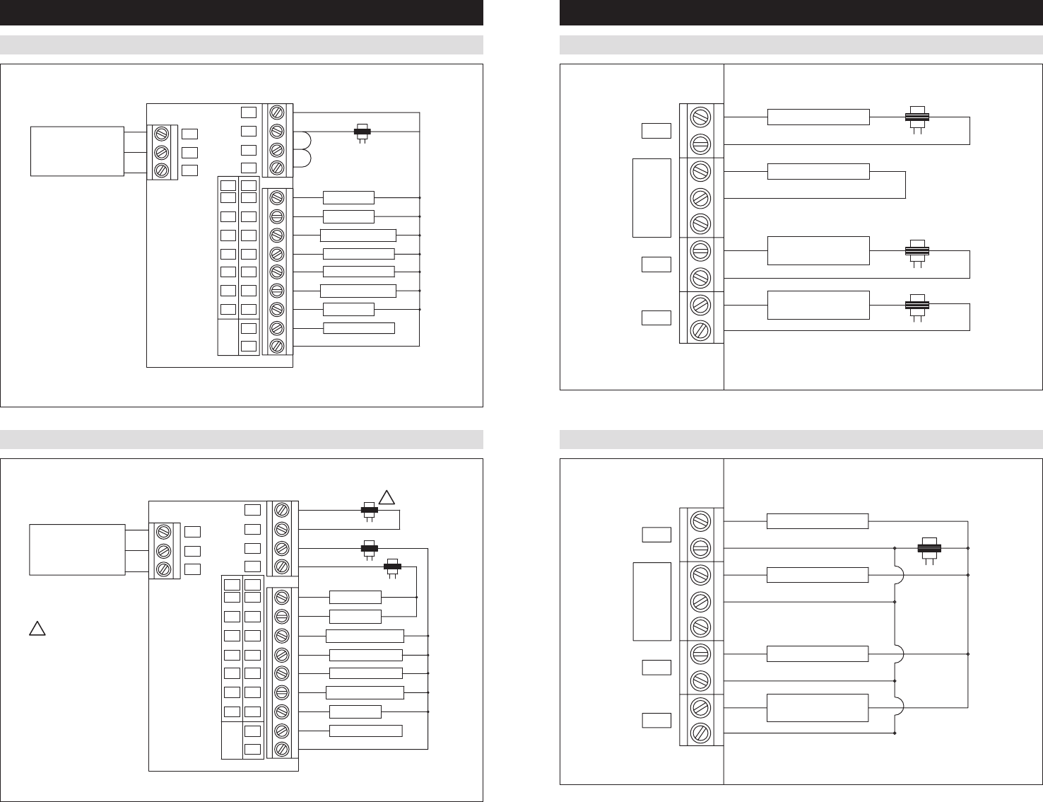
INSTALLATION HVAC WIRING DIAGRAMS
LEAVING AIR TEMPERATURE SENSOR (OPTIONAL)
CONVENTIONAL HEAT/COOL SINGLE TRANSFORMER (USE JUMPER)
Leaving air temperature can be measured by attaching an 8052 sensor to the LAT terminals. The leaving air
temperature sensor measurement is displayed during the installer test for diagnostic purposes.
IMPORTANT
the sensor to report false temperature readings.
shaded areas in figure below.)
2. Mount the sensor according to the installation instructions provided with the sensor.
3. Wire the sensor to the equipment control module LAT terminals.
W
W2
W3
Y
Y2
Y3
G
HC HP
EQ
3
C
RC
RH
L
G
O
Y2
Y
B
W2
W
R
C
TRANSFORMER
2nd HEATING
1st HEATING
THERMOSTAT
FAN
1st COMPRESSOR
2nd COMPRESSOR
2
1
3rd HEATING
3nd COMPRESSOR
LOCATE
AREA.
CONVENTIONAL HEAT/COOL TWO TRANSFORMER (REMOVE JUMPER)
HEATING TRANSFORMER
COOLING TRANSFORMER
C
R
W
W2
B
Y
Y2
O
G
L
RH
RC
C
3
EQ
HPHC
G
Y3
Y2
Y
W3
W2
W
TRANSFORMER
THERMOSTAT
1
2
2nd COMPRESSOR
1st COMPRESSOR
FAN
1st HEATING
2nd HEATING
3rd COMPRESSOR
1R and C can be
powered from the
HVAC equipment
transformer or any
other constantly
powered 24VAC
source.
1
RETURN AIR TEMPERATURE SENSOR (OPTIONAL)
Return air temperature can be measured by attaching an 8052 sensor to the RAT terminals. The return sensor must
be enabled in the installer set-up menu. The return air temperature sensor provides protection in the event that the
the equipment control module will use the return air temperature sensor to maintain a temperature greater than 40°F
and less than 100°F.
1. Locate the Aprilaire Model 8052 sensor
in the return trunk.
2. Mount the sensor according to the
installation instructions provided with
the sensor.
3. Wire the sensor to the equipment
control module RAT terminals.
8 9
Note: Outputs are 24VAC dry contact. Please see individual product installation instructions for more details.
HVAC WIRING DIAGRAMS
HEAT PUMP SINGLE TRANSFORMER (USE JUMPER WIRE)
C
R
W
W2
B
Y
Y2
O
G
L
RH
RC
C
3
EQ
HPHC
G
Y3
Y2
Y
W3
W2
W
FAULT DETECT
REVERSING VALVE
THERMOSTAT
REVERSING VALVE
1
2
2nd COMPRESSOR
1st COMPRESSOR
FAN
1st HEATING
2nd HEATING
HEAT PUMP TRANSFORMER
HEAT PUMP TWO TRANSFORMER (REMOVE JUMPER WIRE)
THERMOSTAT
TRANSFORMER
W
W2
W3
Y
Y2
Y3
G
HC HP
EQ
3
C
RC
RH
L
G
O
Y2
Y
B
W2
W
R
C
HEAT PUMP TRANSFORMER
HEATING TRANSFORMER
1
FAULT DETECT
REVERSING VALVE
REVERSING VALVE
2nd HEATING
1st HEATING
FAN
1st COMPRESSOR
2nd COMPRESSOR
2
1
1R and C can be
powered from the
HVAC equipment
transformer or any
other constantly
powered 24VAC
source.
INDOOR AIR QUALITY WIRING DIAGRAMS
INDOOR AIR QUALITY WIRING WITH SEPARATE TRANSFORMERS
INDOOR AIR QUALITY WIRING WITH A SINGLE TRANSFORMER
TRANSFORMER
TRANSFORMER
TRANSFORMER
VNT
DH
HUM
EAC
DH
DHno
com
nc
DEHUMIDIFIER
NORMALLY
CLOSED DAMPER
HUMIDIFIER
PILOT RELAY FOR
120 VAC TO EAC
nc
com
no
DH
DH
EAC
HUM
DH
VNT
TRANSFORMER
HUMIDIFIER
8120 DAMPER
DEHUMIDIFIER
PILOT RELAY FOR
120 VAC TO EAC
Note: Outputs are 24VAC dry contact. Please see individual product installation instructions for more details.
10 11
POWER & RESET OPTIONS
The equipment control module is powered from
24VAC. The thermostat is powered from the equipment
interface module and has a battery back-up option for
the clock.
The thermostat has a memory backup that saves the
thermostat settings in case of a power interruption.
The system settings will be retained but the clock will
reset after 90 seconds with no battery or equipment
control module power.
The reset button located under the battery cover can
be used to reset the thermostat to factory defaults. The
system settings will also be reset to default.
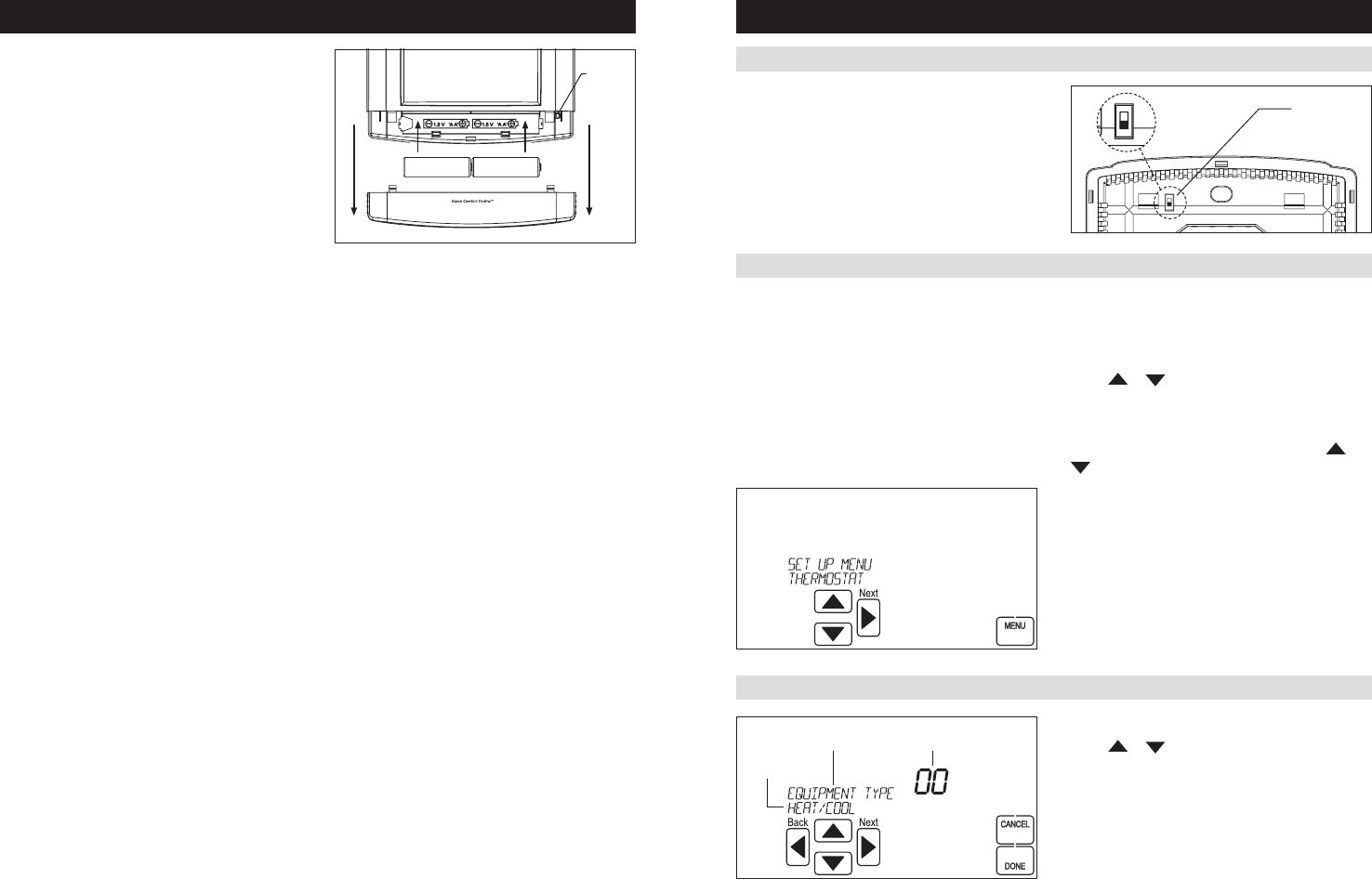
SETUP & TESTING
INSTALLER SETUP MENU
CHANGE SYSTEM SETTINGS
HOW TO ENTER THE INSTALLER SETUP MENU AND SELECT EQUIPMENT TO SETUP:
Press [MODE] to set system to OFF.
Press [MENU] to enter main menu.
Press and hold [SETUP][INSTALL
SETUP] appears.
Press [INSTALL SETUP] to enter installer setup menu.
Press or
Press [MENU]
Press [NEXT] to select option.
Press or
Air Quality) option.
Press [NEXT] to select Outdoor Sensor setting or IAQ
(Indoor Air Quality) option.
System Settings can now be changed.
Press [NEXT] or [BACK] to page through the settings.
Press or
Press [DONE][CANCEL]
without saving.
is pressed within 60 seconds.
the thermostat by pressing the [RESET] button for 5
seconds.
EQUIPMENT TYPE SELECTION SWITCH (SW1)
This Home Comfort Control has the option of being used
in heat pump or heat/cool systems. Switch SW1 located
on the back of the thermostat’s face is used to select this
option. This setting is displayed in the Installer System
Settings under Equipment Type.
Note: Home Comfort Control reboots within 10 seconds
after switch position is changed. HC
HP
SW1
HEAT/COOL
HC
HP
RESET
BUTTON

12 13
System setting Description
Factory default setting (bold)
and setting range
19. Fourth Stage Differential 4th stage differential. 1°F (0.5°C)
1°F to 9°F (0.5°C to 4.5°C)
Disable
Enable
3°F (2°C)
3°F to 5°F (2°C to 3°C)
22. Screen Lockout Screen lockout level. (Override lockout by holding
Off
Part
Full
23. Partial Lockout Type Select lockout type. (Only available when screen
lockout is set to partial.)
Fan/Mode/Setpt
Fan/Setpoints
Setpoints Only
Change In Lockout
Select temperature setpoint limits. (Only available
when screen lockout is set to partial.)
3 degrees
0 to 20 degrees
Change In Lockout
Select dehumidification setpoint limits. (Only
available when screen lockout is set to partial.)
5 Percent RH
0 to 15 Percent RH
25. Stage Rate Accumulation of equipment run time in equipment
staging determination.
1 = more rapid staging of equipment (comfort)
5 = slower staging of equipment (economy)
2
run time.
27. Progressive Recovery Enable or disable progressive recovery. Disable
Enable
Outdoor temperature low balance point. (This
option is only displayed if the outdoor sensor is
enabled.)
20°F (-6°C)
10°F to 50°F (-12°C to 9°C) or OFF to
ignore
Outdoor temperature high balance point. (This
option is only displayed if the outdoor sensor is
enabled.)
65°F (18°C)
40°F to 85°F(3°C to 18°C) or OFF to
ignore
30. Program Format Select weekly program format. 7-Day
5/2 Weekdays (weekdays and weekends)
32. Events Per Day Four
Two
33. Reset Service Reminders Clears the Change Air Filter and HVAC and
Dehumidifier Service reminders if they are active
and resets the start date to the current date.
Clears the Change Water Panel reminder if it is
will be reset.
No
Yes
37. HVAC Service Reminder The period for displaying the “HVAC Service
Off
24VAC is present.
Disable
Enable
100 Percent
0 to 100 Percent
40. Auto Daylight Savings Enable or disable auto daylight savings. Off
March (second Sunday in March to the
April (first Sunday in April to the last
Sunday in October)
SETUP & TESTINGSETUP & TESTING
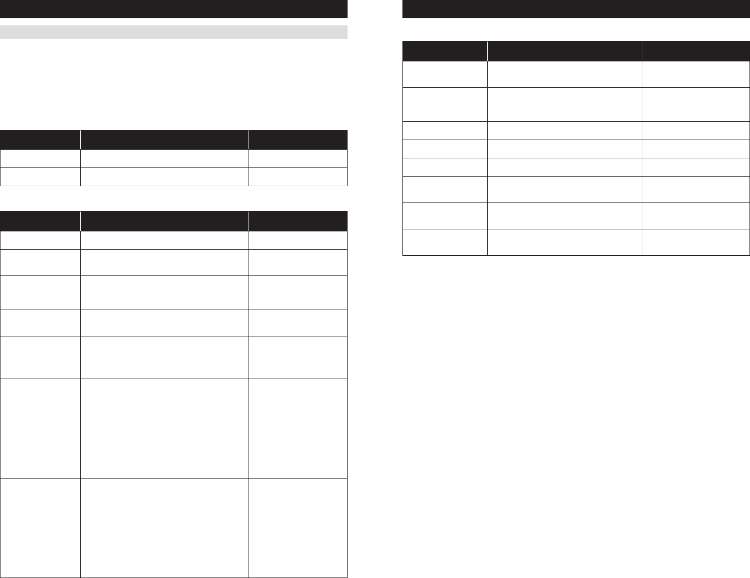
HVAC INSTALLER SYSTEM SETTINGS TABLE (CONTINUED)
The following table contains the system settings and their details. Default settings are shown in bold. Some settings
are only available dependent upon the value of other settings.
HVAC INSTALLER SYSTEM SETTINGS TABLE
System setting Description
Factory default setting (bold)
and setting range
00. Equipment Type Equipment type set by SW1. Heat /Cool
Heat Pump
01. Control Setup
available in Heat/Cool mode.)
Heat and Cool
Heat Only
Cool Only
available in Heat/Cool mode.)
One
Two
Three
One
Two
04. Temperature Scale Set the thermostat to Fahrenheit or Celsius mode. Fahrenheit
Celsius
05. Heat/Cool: Fan Control
in Heating
Equipment Type
Heat/Cool: Determines if the thermostat or
equipment controls the fan in heating.
Gas/Oil Heat (equipment controls fan)
Electric Heat (thermostat controls fan)
Disable
Disable
08. Internal Temp Sensor
Offset
0° (no offset applied)
-4°F to +4°F (-2°C to +2°C)
35. Internal RH Sensor Offset 0 (no offset applied)
-5% to +5%
09. Auto Changeover Enable or disable auto changeover mode. Disable
Enable
26. Deadband Auto Changeover mode deadband. 3°F (2°C)
2°F to 9°F (1°C to 5°C)
10. Remote Sensor Select if remote sensor is attached. No
Yes
11. Outdoor Sensor Select if outdoor sensor is attached or not. No
Yes
35. Return Sensor Select if return sensor is attached or not. No
Yes
12. Compressor Min Off Time Minimum off time for compressor protection. 5 minutes
1 to 5 minutes
13. Heating Min Off Time Minimum off time for heating. 2 minutes
1 to 5 minutes
14. Equipment Min On Time Minimum on time for heating and cooling. 2 minutes
1 to 5 minutes
15. Auto Changeover Time Minimum time between heating and cooling calls. 4 minutes
1 to 5 minutes
16. First Stage Differential 1st stage differential. 1°F (0.5°C)
1°F to 9°F (0.5°C to 4.5°C)
17. Second Stage Differential 2nd stage differential. 1°F (0.5°C)
1°F to 9°F (0.5°C to 4.5°C)
18. Third Stage Differential 3rd stage differential. 1°F (0.5°C)
1°F to 9°F (0.5°C to 4.5°C)
14 15
SETUP & TESTINGSETUP & TESTING
The following tables contain the Indoor Air Quality system settings and their details. Default settings are shown in
bold. Some settings are only present dependent upon the value of other settings.
The use of an outdoor temperature sensor (recommended) enables additional Indoor Air Quality functionality. If the
will be presented prior to entering the Indoor Air Quality system settings.
Please refer to the Model 8910 Owner’s Manual for further information about Home Comfort Control features.
Air Cleaning System Settings Table
System setting Description
Factory default setting (bold)
and setting range
Air Cleaner Installed
air cleaning settings will be available.)
No
Yes
Change Air Filter Reminder Off
Humidifier System Settings Table
System setting Description
Factory default setting (bold)
and setting range
Humidifier Installed
humidifier settings will be available.)
No
Yes
Humidity Setpoint
Deadband
Select the minimum difference between the humidifier and
dehumidifier setpoints. (Only available if both a humidifier
and dehumidifier are installed. Available in both set-ups.)
10 Percent RH
10 to 20 Percent RH
Humidifier Mode Selects auto or manual mode. Auto mode controls humidity
based on the humidity setting and outdoor temperature.
Manual mode controls humidity based on the %RH setpoint.
(Auto mode is only available if outdoor sensor is set to yes.)
Auto
Manual
Humidifier Operation Selects when humidification is allowed to occur relative to
heating and fan operation.
Heat Only
Heat or Fan
Forces Fan
Change Water Panel
Reminder
displayed.
Off
1 Per Season
2 Per Season
300 Hours
600 Hours
Reminder Month (Change
Water Panel Reminder set
to 1 per Season)
First Reminder Month
(Change Water Panel
Reminder set to 2 per
Season)
Change Water Panel Reminder set to 1 per Season:
is displayed.
Change Water Panel Reminder set to 2 per Season:
message is displayed.
October
December
January
February
March
April
May
June
July
August
September
Second Reminder Start
Month
message is displayed. (Only available when Change Water
Panel Reminder set to 2 per Season.)
October
December
January
February
March
April
May
June
July
August
September
INDOOR AIR QUALITY SYSTEM SETTINGS TABLES Dehumidifier System Settings Table
System setting Description
Factory default setting (bold)
and setting range
Dehumidifier Control
other dehumidifier settings will be available.)
None (no dehumidification installed)
Whole Home
Air Conditioner
Humidity Setpoint Deadband Select the minimum difference between the humidifier
and dehumidifier setpoints. (Only available if both a
humidifier and dehumidifier are installed. Available in
both set-ups.)
10 Percent RH
10 to 20 Percent RH
Lockout Dehumidifier During
Cooling
Selects if dehumidification is disabled during a cooling
call.
Yes
Dehumidifier Forces Fan Select if dehumidification can turn on the fan.
Yes
Dehumidifier Service
Reminder
The period for displaying the “Dehum Service
Off
Dehumidifier Overcooling
Limit
Selects the amount of overcooling that can occur for
dehumidification. (Only available if dehum control is
set to air conditioner.)
3°F (1.5°C)
1°F to 3°F (0.5°C to 1.5°C)
Dehumidify in Vacation
Mode
Selects if dehumidification with the air conditioner
is done in Vacation Mode. (Only available if dehum
control is set to air conditioner.
No
Yes
Vacation Dehumidifier Low
Temp Limit
Sets the lowest temperature the air conditioner will
cool to meet RH setpoint in Vacation Mode. (Only
available if dehum control is set to air conditioner.)
75°F (24°C)
70°F to 85°F (21°C to 29°C)
Note:
installation and operation.
16 17
SETUP & TESTING
Ventilation System Settings Table
System setting Description
Factory default setting (bold)
and setting range
Fresh Air Vent Installed Selects if ventilation is installed.
No
Yes
Fresh Air Forces Fan Selects if ventilation forces the fan on.
Yes
Fresh Air Setup Selects if ventilation is configured through the ASHRAE setup
time will be calculated using the ASHRAE recommendations.
determined based on the Fresh Air Time value.
Timed
ASHRAE
Fresh Air Time Selects how many minutes per hour that ventilation will be
active. (Only available if fresh air setup is set to timed.)
30 MIN/HR
High Limit Outdoor
Temp
Selects if ventilation is disabled if the outdoor temperature
is set to timed and an outdoor temperature sensor is installed.)
No
Yes
Outdoor High Limit Sets the high temperature limit for ventilation. (Only available if
high limit outdoor temp set to yes.)
100°F (38°C)
90°F to 100°F (32°C to 44°C)
Low Limit Outdoor Temp Selects if ventilation is disabled if the outdoor temperature
is set to timed and an outdoor temperature sensor is installed.)
No
Yes
Outdoor Low Limit Sets the low temperature limit for ventilation. (Only available if
low limit outdoor temp set to yes.)
10°F (-7°C)
-10°F to 30°F (-29°C to -1°C)
High Limit Indoor RH
the indoor RH limit. (Only available if fresh air setup is set to
timed.)
No
Yes
Indoor RH Limit Sets the high indoor RH limit for ventilation. (Only available if
high limit indoor RH is set to yes.)
60%
50% to 70%
Selects the number of bedrooms to be used for the ASHRAE
calculation. (Only available if fresh air setup is set to ASHRAE.)
3 Bedrooms
Selects the number of occupants to be used for the ASHRAE
calculation. (Only available if fresh air setup is set to ASHRAE.)
4 Occupants
1 to 10 Occupants
Home Size Selects the home size to be used for the ASHRAE calculation.
(Only available if fresh air setup is set to ASHRAE.)
2500 SQ FT
1000 to 5000 SQ FT
Fresh Air CFM Selects the ventilation CFM to be used for the ASHRAE
calculation. (Only available if fresh air setup is set to ASHRAE.)
60 CFM
30 to 200 CFM
Select Climate Selects the climate to be used for the ASHRAE calculation.
(Only available if fresh air setup is set to ASHRAE.)
Normal
Very Hot/Humid
Very Cold
ASHRAE Cycle Time Displays the Fresh Air Time calculated by the ASHRAE
standard. (Only displayed if fresh air setup is set to ASHRAE.)
Minutes/Hour
Note: In ASHRAE set-up temperature and humidity limits are disabled.
SETUP & TESTING
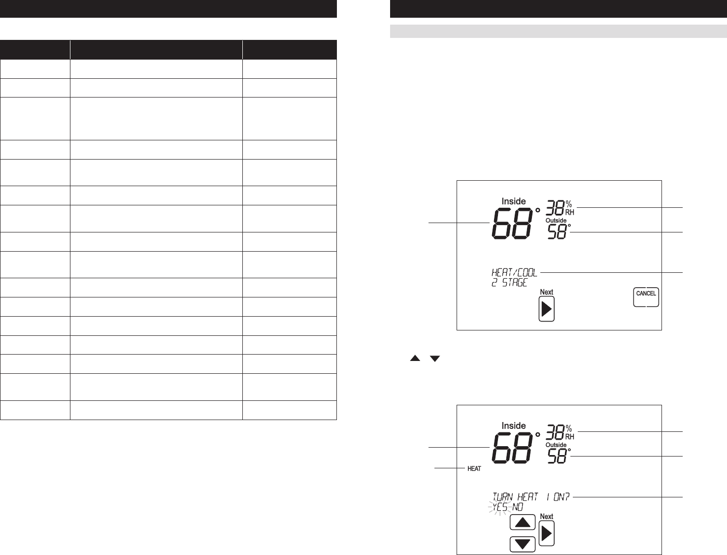
SYSTEM TEST MENU
The system test menu is used to test a system after installation. The outputs of the Home Comfort Control can be
manually activated to test their function. The instructions below show how to enter the test mode and turn outputs
on and off.
Each equipment test will begin with the selection of turning on the output or stage as shown below.
Press or to change the selection.
Press [NEXT]
If YESNO
SYSTEM TEST STEPS
Heating equipment test
Cooling equipment test
Fan equipment test
Humidification equipment test
Dehumidification equipment test
Ventilation equipment test
Air Cleaning equipment test
HOW TO ENTER THE SYSTEM TEST MENU:
Press [MODE] to set system to off.
Press and hold [FAN] and [MODE] for three seconds
to enter system test mode.
The first screen of the installer test displays the
equipment configuration.
Press [NEXT] to enter the first installation test or
[CANCEL]
18 19
SETUP & TESTING SETUP & TESTING
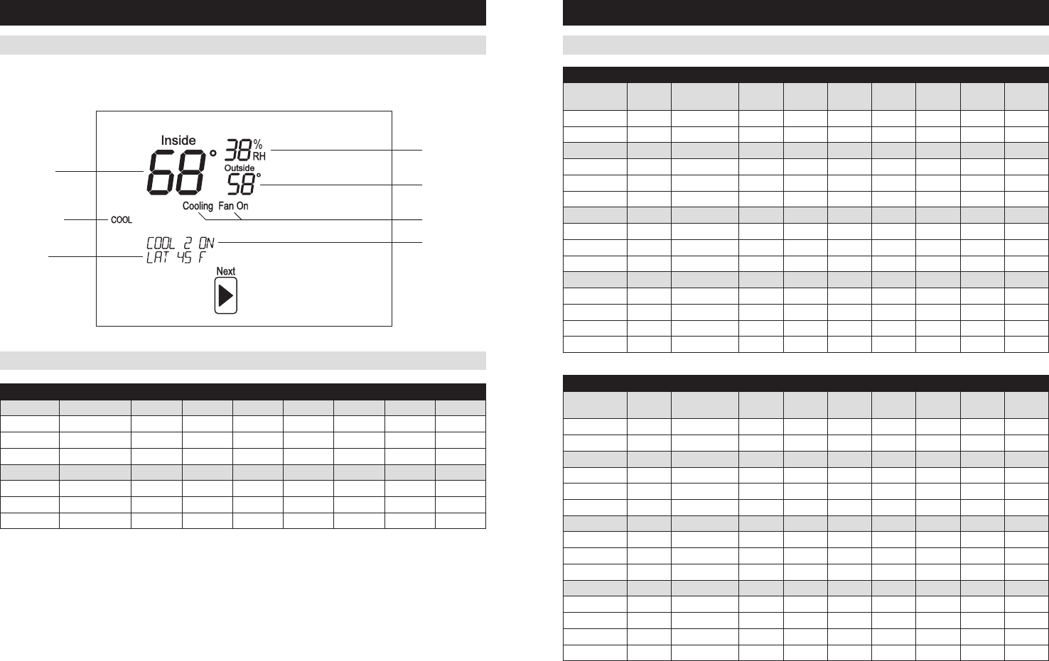
SYSTEM TEST MENU (CONTINUED) SYSTEM TEST TABLES (CONTINUED)
SYSTEM TEST TABLES
While the equipment test is active the corresponding test information will be shown.
Press [NEXT]
TEST THAT
IS ACTIVE
Heat / Cool Heating Equipment Test
Heat Type W W2 W3 Y Y2 Y3 G
1st Stage Test
2nd Stage Test
3rd Stage Test
Electric 1st Stage Test
Electric 2nd Stage Test
Electric 3rd Stage Test
Heat Pump Heating Equipment Test (Electric Heat)
Compressor
Stages
Aux
Stages W W2 B Y Y2 O G
1 1 1st Stage Test
1 1 2nd Stage Test
2 1 1st Stage Test
2 1 2nd Stage Test
2 1 3rd Stage Test
1 2 1st Stage Test
1 2 2nd Stage Test
1 2 3rd Stage Test
2 2 1st Stage Test
2 2 2nd Stage Test
2 2 3rd Stage Test
2 2 4th Stage Test
Heat Pump Heating Equipment Test (Gas Heat)
Compressor
Stages
Aux
Stages W W2 B Y Y2 O G
1 1 1st Stage Test
1 1 2nd Stage Test
2 1 1st Stage Test
2 1 2nd Stage Test
2 1 3rd Stage Test
1 2 1st Stage Test
1 2 2nd Stage Test
1 2 3rd Stage Test
2 2 1st Stage Test
2 2 2nd Stage Test
2 2 3rd Stage Test
2 2 4th Stage Test
20 21
Heat / Cool Cooling Equipment Test
W W2 W3 Y Y2 Y3 G
1st Stage Test
2nd Stage Test
3rd Stage Test
Heat Pump Cooling Equipment Test
W W2 B Y Y2 O G
1st Stage Test
2nd Stage Test
Fan Equipment Test
W W2 W3/B Y Y2 Y3/O G
Humidification Equipment Test
HUM DHNO/DHCOM VENT EAC G
Dehumidification Equipment Test
HUM DHNO/DHCOM VENT EAC G
Ventilation Equipment Test
HUM DHNO/DHCOM VENT EAC G
Ventilation Equipment Test
HUM DHNO/DHCOM VENT EAC G
SETUP & TESTING
SYSTEM TEST TABLES (CONTINUED)
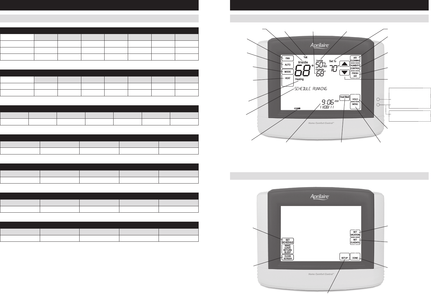
QUICK REFERENCE TO CONTROLS & DISPLAY
HOME SCREEN
MAIN MENU
NOTE:
SYSTEM MODE
SYSTEM MODE
™ AIR
(SETS OR CLEARS HOLD)
HEAT PUMP ONLY
22 23
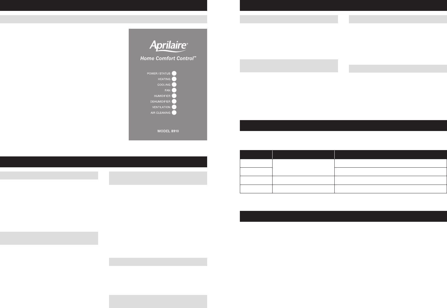
TROUBLESHOOTING
TROUBLESHOOTINGQUICK REFERENCE TO CONTROLS & DISPLAY
DISPLAY IS BLANK
If Power LED not illuminated at the equipment control
module check the following.
system is on.
POWER/STATUS – On solid during normal operation. Flashes
when connection to the thermostat is lost and at power-up while
the thermostat connection is being established.
HEATING – On when heating outputs are active.
COOLING – On when cooling outputs are active.
FAN – On when fan output is active.
HUMIDIFIER – On when humidifier output is active.
DEHUMIDIFIER – On when dehumidifier output is active.
VENTILATION – On when ventilation output is active.
AIR CLEANING – On when air cleaner output is active.
HEATING SYSTEM DOES NOT RESPOND
(“HEATING” APPEARS ON SCREEN)
side of the transformer between power and
equipment to find the cause of the problem.
the Home Comfort Control is functional. Check the
heating equipment to find the cause of the problem.
Comfort Control and the heating equipment.
COOLING SYSTEM DOES NOT RESPOND
(“COOLING” APPEARS ON SCREEN)
side of the transformer between power and
equipment to find the cause of the problem
the Home Comfort Control is functional. Check the
cooling system to find the cause of the problem.
Comfort Control and the cooling equipment.
FAN DOES NOT TURN ON IN A CALL FOR HEAT
the fan control is properly set to match the type of
system.
HEAT PUMP ISSUES COOL AIR IN HEAT MODE,
OR WARM AIR IN COOL MODE
reversing valve is connected to the proper terminal.
HEAT/COOL BOTH ON AT SAME TIMEEQUIPMENT CONTROL MODULE LEDs
to match the installed heating/cooling equipment.
not shorted together.
HEATING EQUIPMENT IS RUNNING IN
COOL MODE
to match the installed heating/cooling equipment
(see page 11).
“HEATING” IS NOT DISPLAYED
(Control Setup) is set correctly.
the temperature level above the current room
temperature.
“COOLING” IS NOT DISPLAYED
(Control Setup) is set correctly.
the temperature level below the current room
temperature.
ERROR CODES
Error code Message Error Description
01 Open temperature sensor circuit
02 Shorted temperature sensor circuit
03 Error in permanent memory
05 Thermostat lost connection to equipment interface module
HOME COMFORT CONTROL™ FEATURES
– Humidification automatic or manual control.
– Dehumidification.
™ air cleaning.
– Ventilation with temperature and humidity limits.
™ raises the room temperature 3°F to 5°F.
sensor.
constant backlight option available.
weekday/weekend schedules.
programming (batteries must be installed).
reminders.
schedule at any time.
the start of a program event.
your equipment.
24
www.aprilairepartners.com
61000850 12.11
Patent Pending
© 2011 Aprilaire – A division of Research Products Corporation
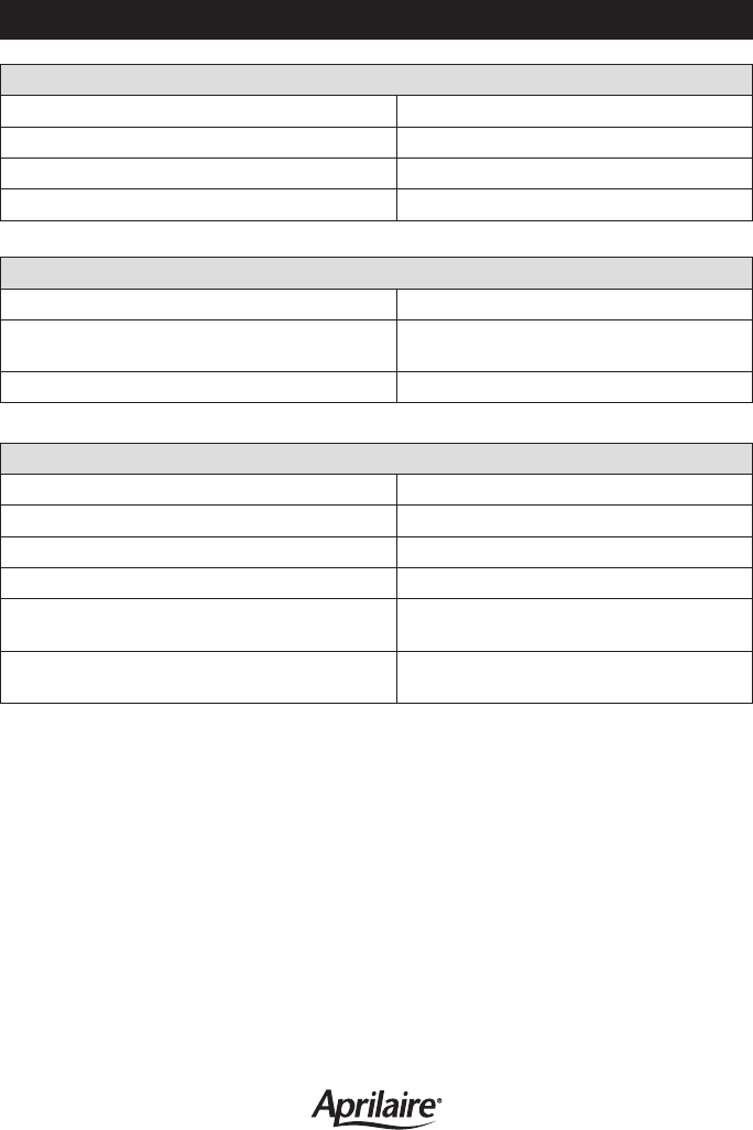
Control
Room temperature measurement Display range: 32° to 99°F (0° to 40°C)
Return and Leaving temperature measurement Display range: -20° to 160°F (-30° to 71°C)
Outdoor temperature measurement Display range: -20° to 130°F (-30° to 55°C)
Setpoint temperature range Heat: 40° to 90°F (4° to 32°C)
Cool: 50° to 99°F (10° to 37°C)
Setpoint humidity range Humidification: 10% to 50% R.H.
Dehumidification: 50% to 90% R.H.
SPECIFICATIONS
Electrical
Operating voltage 24VAC (18 – 30VAC)
Current
Environment
Temperature (Shipping) -30° to 150°F (-34° to 65°C)
Temperature Thermostat (Operating) 32° to 120°F (0° to 48°C)
Temperature Equipment Control Module (Operating) 32° to 158°F (0° to 70°C)
Relative humidity Operating: 5% to 90% R.H. (non-condensing)
