AquaCheck ACCPROBE AquaCheck BASIC-II User Manual
AquaCheck (Pty) Ltd AquaCheck BASIC-II Users Manual
UserManual.wiki
>
AquaCheck
>
ACCPROBE User Manual
Users Manual
Navigation menu
Upload a User Manual
Namespaces
Wiki Guide
HTML
PDF
Info
Views
User Manual
Discussion / Help
Navigation

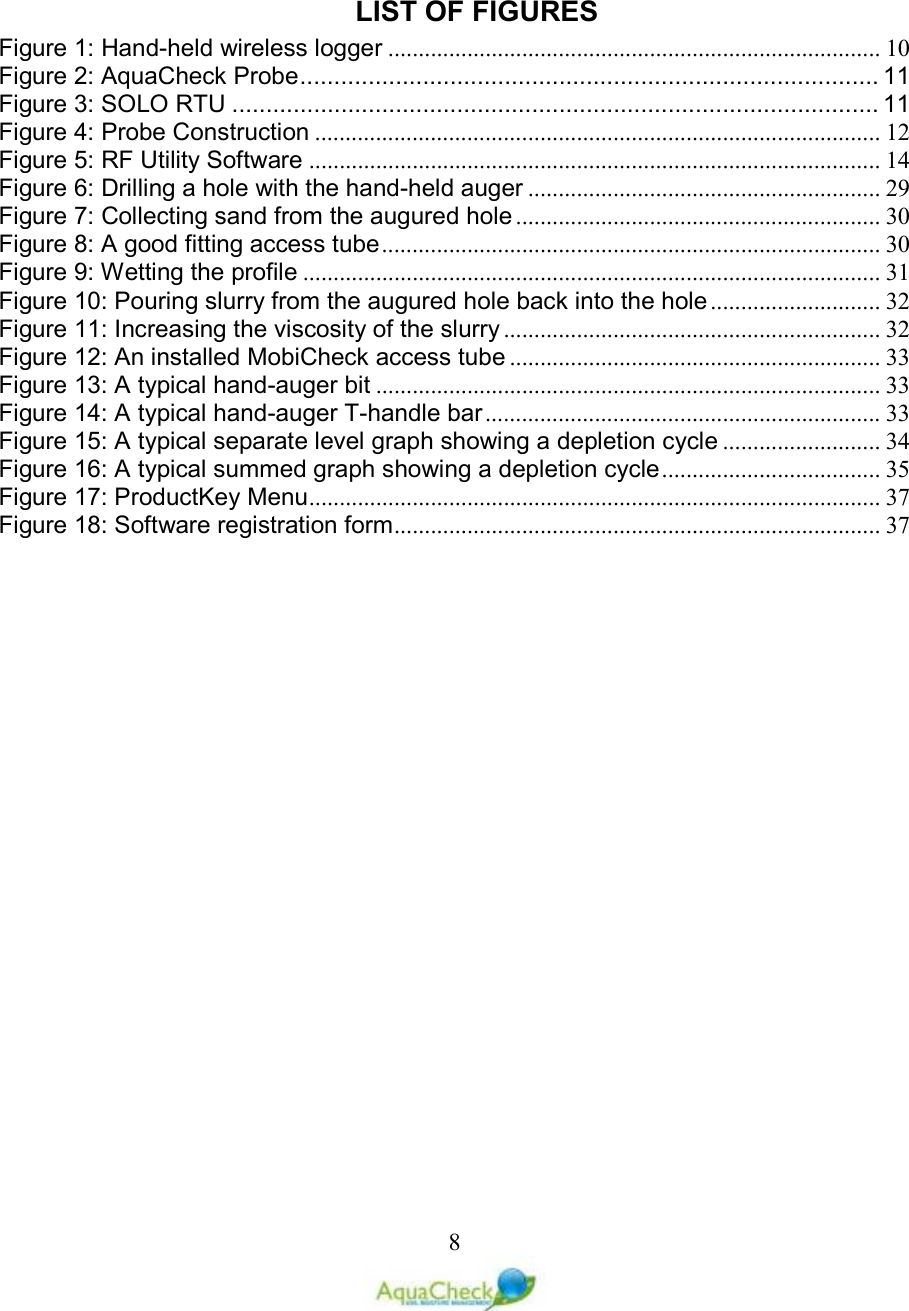
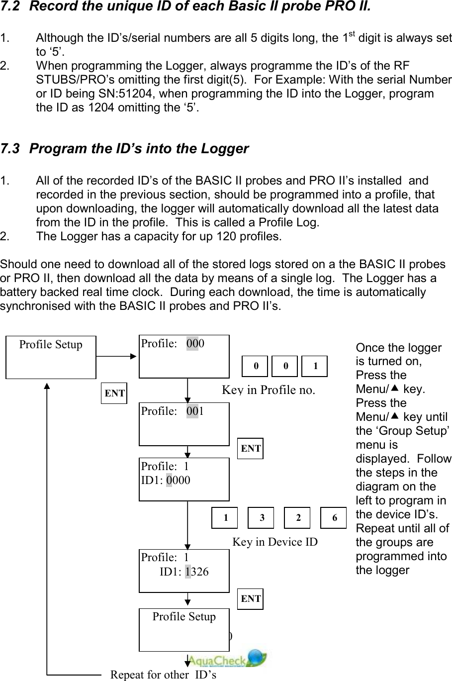
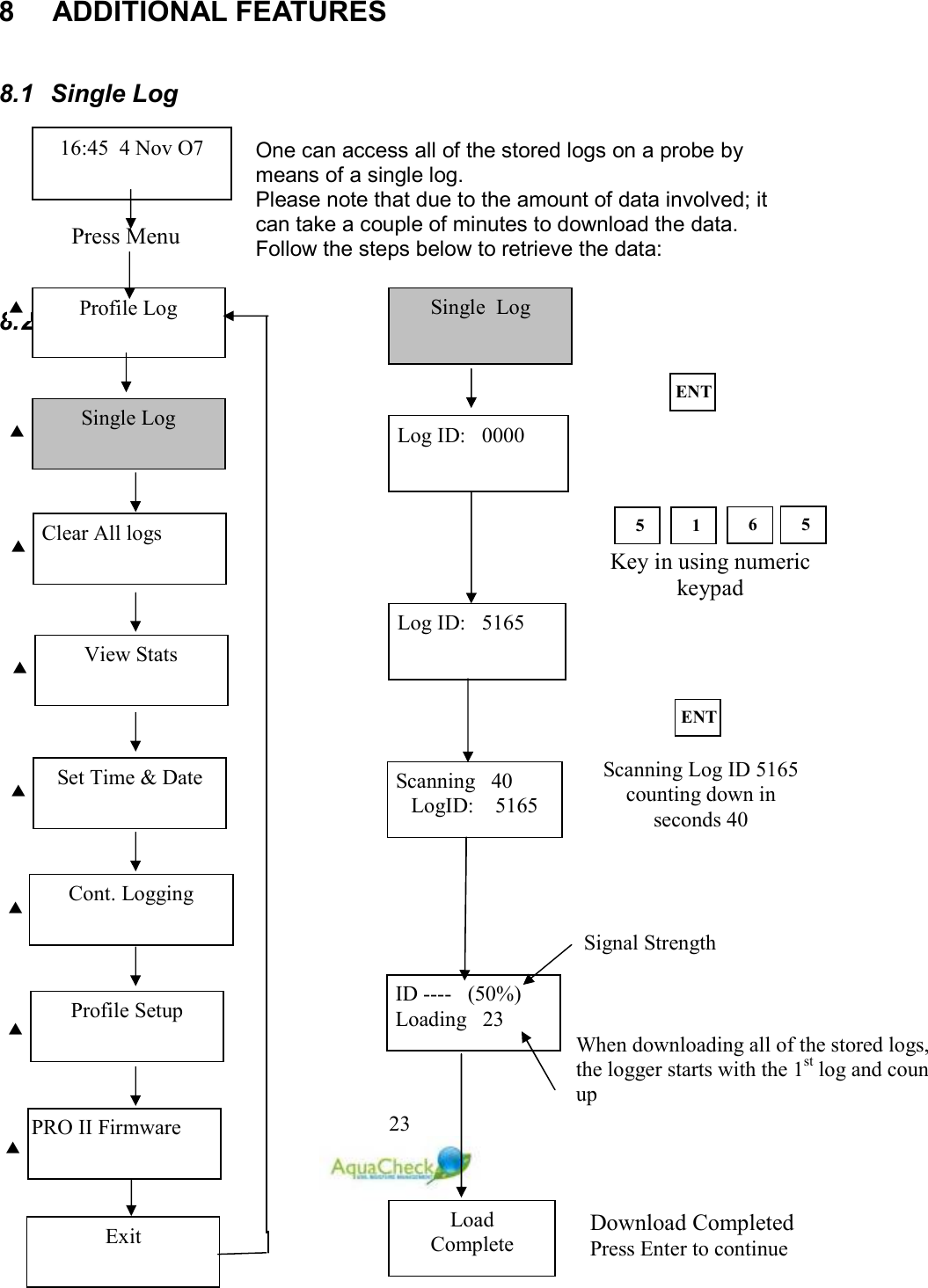
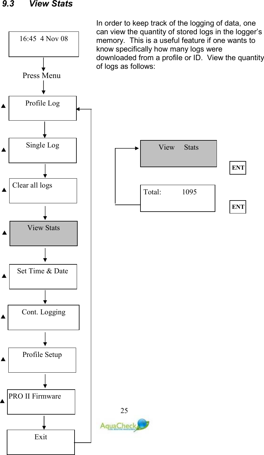
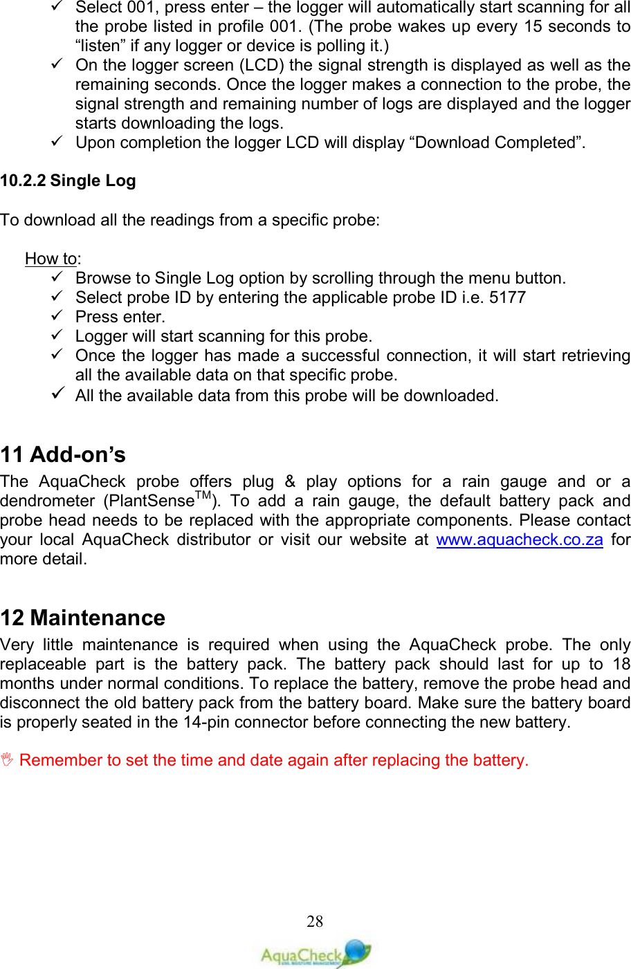
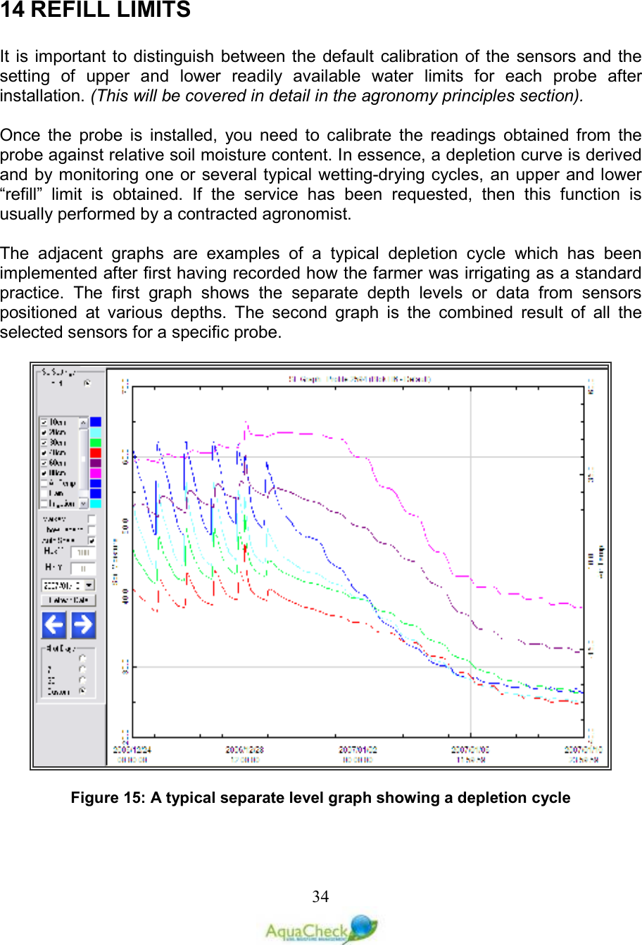
![249.2 Clear All Logs Once all of the data is downloaded to a PC, the databank of the logger should be cleared. To clear the databank follow the instructions below: 8.3 Clear All Logs ET Confirm? [No ] Confirm? [Yes] ET Press Menu Profile Log 16:45 4 Nov O7 Single Log Clear All logs View Stats Set Time & Date Cont. Logging Profile Setup PRO II Firmware Exit](https://usermanual.wiki/AquaCheck/ACCPROBE/User-Guide-1346786-Page-24.png)