Aquamate ACTIVE-X Radar Target Enhancer User Manual
Aquamate Products Limited Radar Target Enhancer Users Manual
Aquamate >
Users Manual
...a significant advance in marine safety!
Radar Target Enhancer
Radar Target Enhancer
Ac t i v e-X- B a n dAc t i v e-X- B a n d
Manufactured by
Echomax Products in the UK
PO Box 6032, Dunmow CM6 3AS, UK.
Email: echomaxsales@aol.com www.echomax.co.uk
Tel: 00 44 (0)1371 830216 Fax: 831733
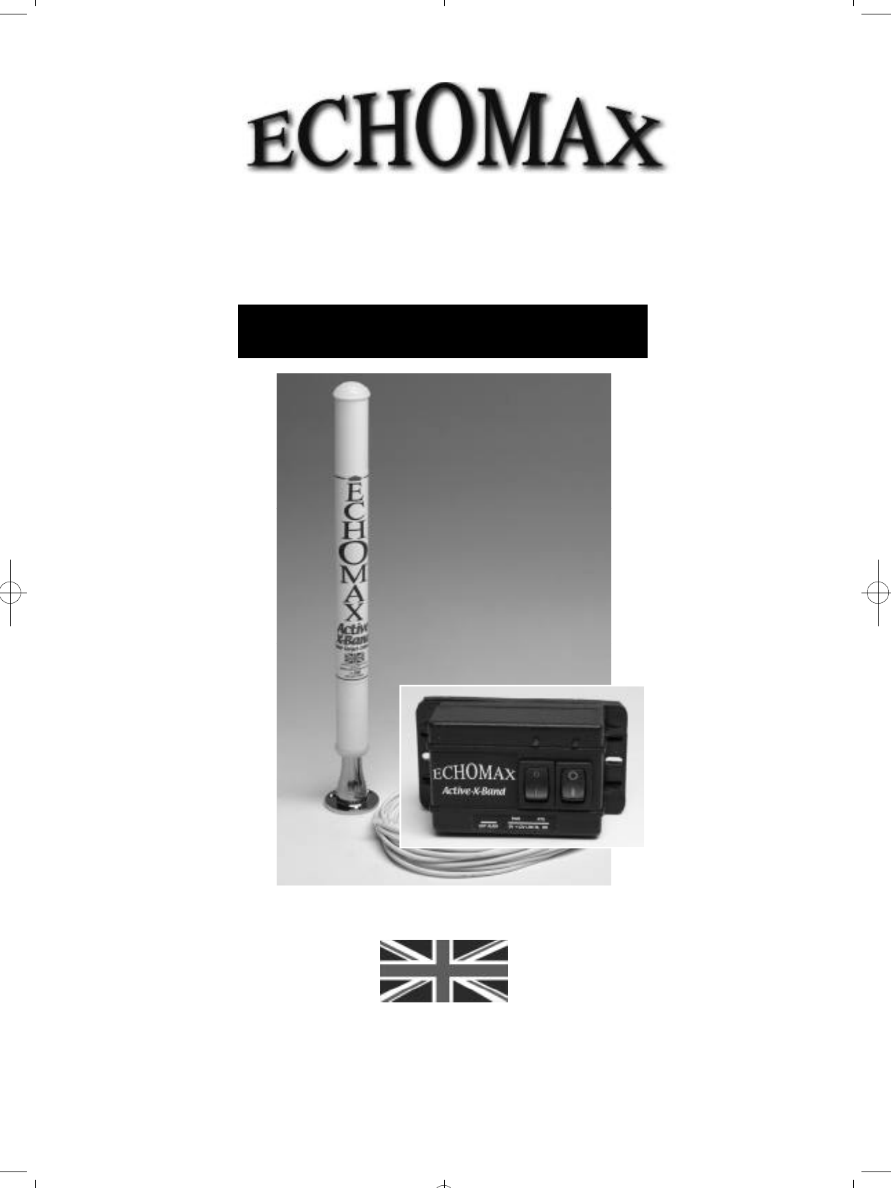
OPERATION MANUAL
Echomax Active-X-Band RTE shown with optional Stainless base fitting
Radar Target Enhancer
Radar Target Enhancer
Ac t i v e-X- B a n dAc t i v e-X- B a n d
GENERAL INTRODUCTION
The Echomax Active-X Radar Target Enhancer (RTE) is designed to respond to interrogating X band
radar (9.3 – 9.5GHz) by receiving a transmitted pulse and amplifying the pulse and re-transmitting the
pulse back to the radar at the same frequency with minimum delay, thereby improving the radar
detection range and visibility of small targets. It will not enhance significantly vessels with
large radar cross section.
The RTE is primarily intended for small vessels with no radar fitted and typically should enhance the
RCS (radar cross section) of vessels up to 25M in length. For small craft/rigid inflatables improvements
will start to be seen at around 1-2 miles extending to 8-10 miles or more depending on prevailing
conditions. The response of the RTE will vary according to range, RTE and radar height above sea level,
radar power and condition. Poor weather, sea state and precipitation will greatly reduce the response
IMPORTANT
The fitting of the Echomax Active-X does not exclude
you from exercising safe navigational judgement for
your vessel under the International Regulations for the
Prevention of Collisions at Sea and to keep a proper
look out at all times
LICENSING REQUIREMENTS
Many countries and administrations require a ships
radio license or modification of your existing ships
radio licence before Active-X can be used for maritime
use. Contact your local administration for details.
ECHOMAX ACTIVE-X COMPONENTS,
CONSTRUCTION, use and installation
If you are not able to safely install the unit yourself
you are advised to seek the services of a competent
person or company to install the RTE.
COMPONENTS
Echomax Active-X mast head radome fitted with
24 meters of 2 core cable
Control box
Operation manual
RADOME FITTING
The antenna has provisions in the base for a 1 inch -
14 NF female thread mast fitting or deck mount
bracket. Plastic mounts should not be used. To ensure
a permanent fixing ‘LOCTITE’ or PTFE or plumbers
tape should be used and the RTE must be screwed
down tightly. Care must be taken to ensure that as the
RTE is tightened on the base the cable is allowed to
turn freely.
For mast fitting the radome must be fitted verticallly
as high as possible. The recieve/ transmit antennas
positioned 70mm from the base of the radome and
have a clear 360 degree azimuth. It should be fitted
at least 6 inches/150mm from the mast on the offset
bracket. It should not be fitted on a back stay or
where its vision is obscured or is close to any metal
object otherwise performance could be significantly
impaired.
The radome unit must never be painted as this will
seriously impair performance. The radome must not
be fitted in or close to the vessels radar transmitting
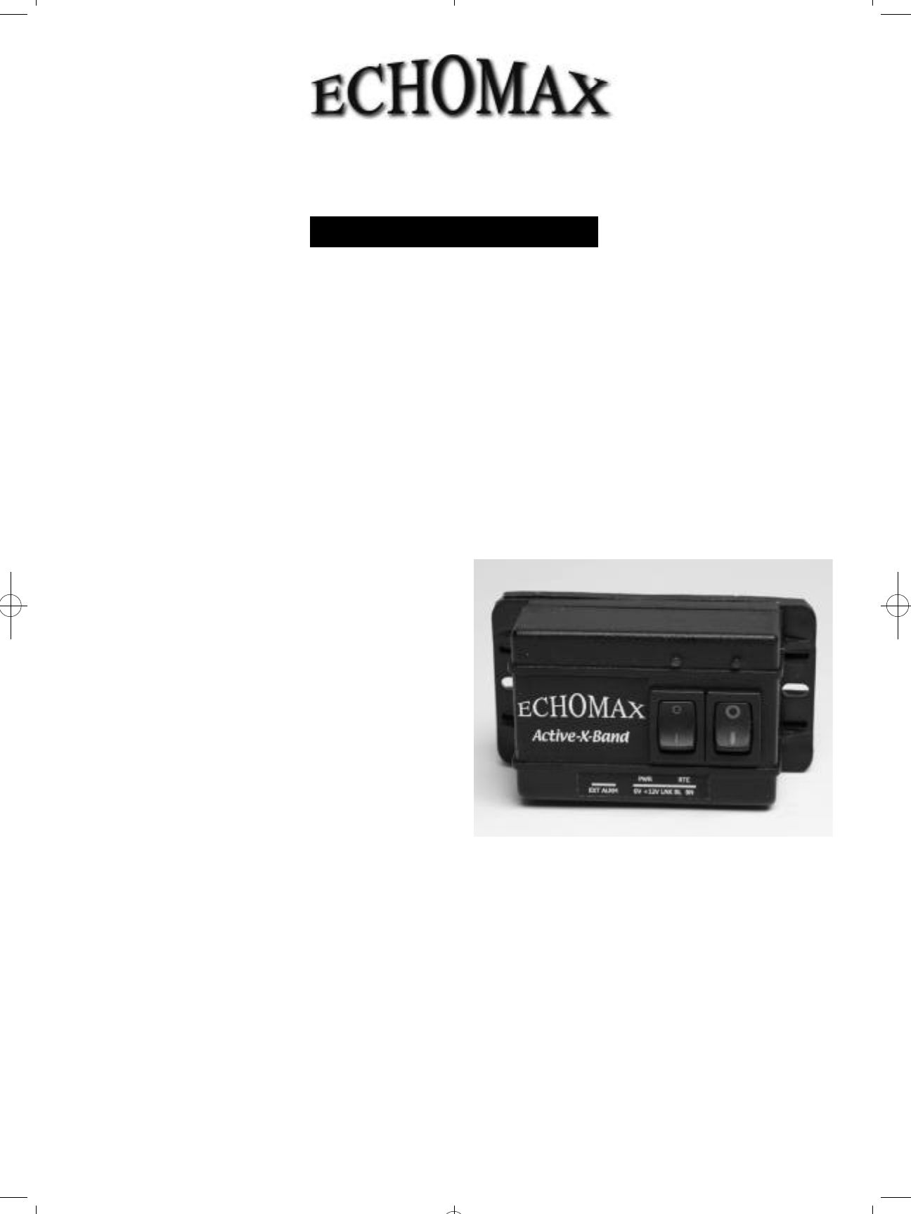
ECHOMAX CONTROL BOX, use and wiring
instructions
The control box must be fitted internally as it is not
waterproof and can be wired from the base or back as
required. A 12v fused or circuit breaker supply of 3-5A
is required.
The control box has a triple alarm facility.
Once the red power switch is turned on the unit is
in the quiescent mode and will consume up to 15mA.
When interrogated by a radar the green LED light will
flash every 2.4 seconds. If the flash lengthens then
this indicates that more than one radar is painting
the antenna. If painted by a high speed radar which
rotates every 1.5 seconds then the LED light will flash
quicker. Turning on the green switch will mobilize the
i n t e rnal buzzer, which is set to actuate for appro x i m a t e l y
half a second intervals. The control box also has
facilities for a 8A external volt free alarm.
The control box has an externally replaceable 0.5A
fuse and is surge and cross polarity protected.
beam width of 23 degrees as this may seriously damage
the PCB. The RTE should be fitted below or preferably
above the radar. It is possible to shorten or extend
the cable by a further 25 meters without affecting the
p e rf o rm a n c e using extension cable rated at 3A at 300V.
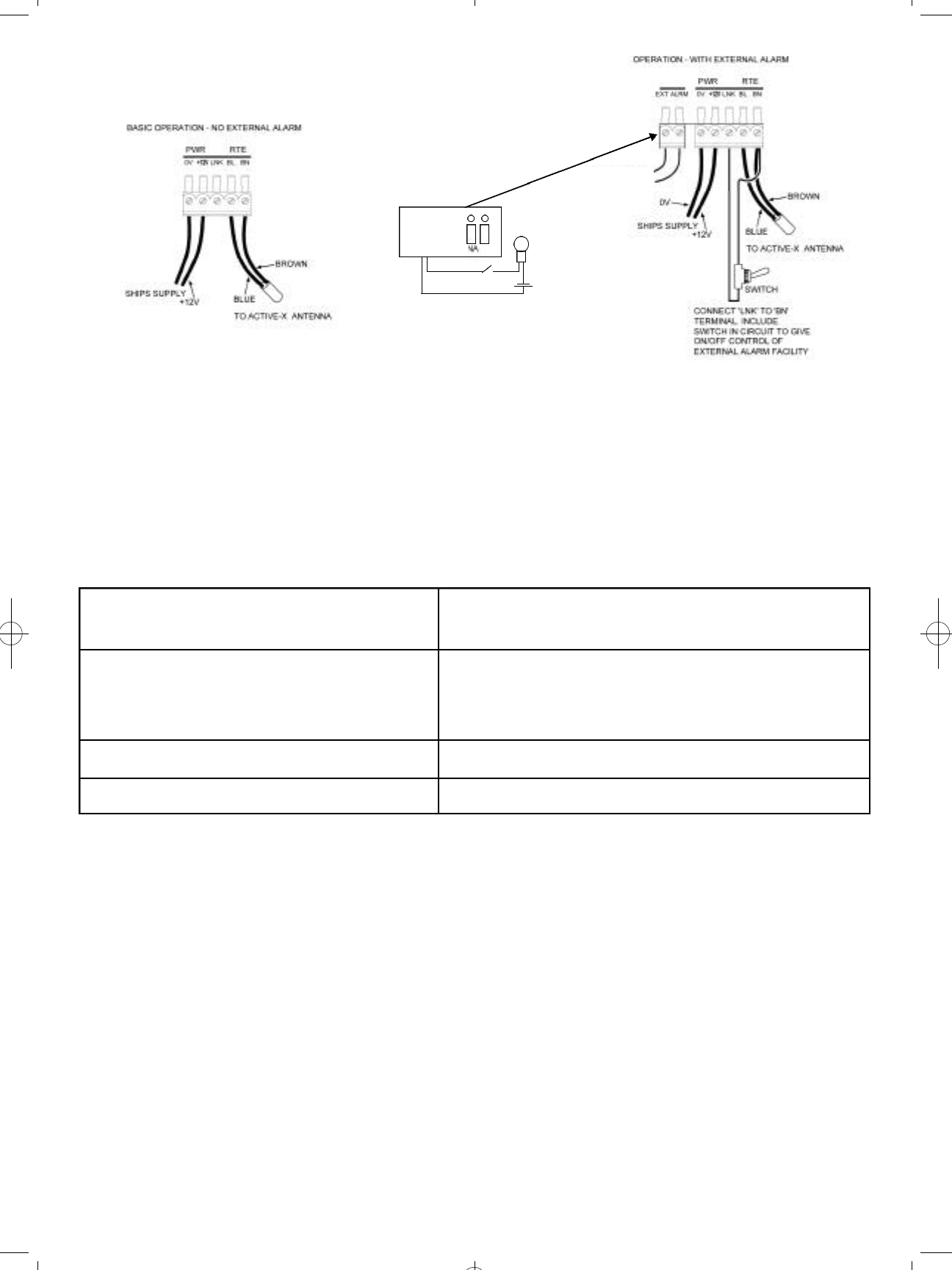
RTE CONNECTIONS
The diagrams show the correct wiring installation
PERFORMANCE CHECK
As the RCS of your vessel may exceed the RCS of the RTE, the trial is best carried out at 0.5 nm as the target
can be easily identified. The range should then be increased at intervals of 0.5 nm and the RTE switched on and
off noting the change in response. As the range increases the bare target will not be seen and whilst moving the
RTE is left on so that the test target can be seen at all times. This is important in busy waters to avoid confusion
with other vessels.
If the target is lost it can be acquired by turning the RTE on and off and watching the display for change in
target response. In normal weather and sea conditions, with RTE and interrogating radar mounted at four meters
above sea level should respond on the radar screen as shown below. If the mounting heights, including that of the
interrogating radar vary so will the response due to curvature of the earth. These figures are for guidance only and
should not be relied upon.
2KW radar up to 4 nm : 5KW radar up to 10 nm : 10- 25KW radar up to 15-20 nm
FAULT FINDING CHART
No Red LED light when red switch Check fuse or circuit breaker
is turned on Check polarity of wiring
Check power supply at control box
Damaged cable or wrong connection
Unit switched on and continuous green Local radar on, or radar operating moored nearby (<15M)
LED light shows, in harbour or when Moored close to large metal object
saturating RTE Check polarity of radome wiring
Being actuated by ships own radar – turn off radar and if
necessary relocate Active-X
Relocate vessel to more suitable position
Unit on and buzzer on and unit fails to Check all above faults. Is RTE in shadow of
operate when it clearly is interrogated interrogating radar as it will not operate if masked
Buzzer switched on but does not sound Buzzer faulty – return control box to Echomax
when painted by radar for inspection
TECHNICAL SPECIFICATION
Operating frequency X band (9.3-9.5GHz)
Position Accuracy Within 1 meter
Dimensions and Weight of radome ex cable L 478mm W 40.5mm wt 327 grms
Cable 24M 2 core 0.5mm2wt 969grms
Base Mounting 1 inch – 14 NF female thread
Dimensions of control box W 92mm H 51mm D 38mm
Externally accessible fuse 0.5A
Power supply 12V DC – 30% - 10% voltage surge
and cross polarity protected
Stand by current consumption in quiescent state < 15mA
5 interrogating radar 23mA (typically)
10 interrogating radar 32mA (typically)
EIRP 1W (typically)
Stated Performance Level (SPL) Exceeds ISO 87292-2 X Band requirement of 7.5M2SPL
at Zero, +/-10 and 20 degrees of heel✽
Compass safe distance 1 metre
✽Active-X tested QinetiQ - Funtington 13th March 09
zero degrees 111.36M2
+/- 10 degrees of heel 78.96M2
+/- 20 degrees of heel 20.80M2
CONTROLBOX
SWITCHED
CONTACT
(RELAY) FOR
EXTERNALALARM
SWITCH
SHIPS
SUPPLY
LAMP
EXTERNAL ALARM
+12V
-12V

Echomax Active-X-Band RTE shown with optional
Stainless base fitting
STAINLESS STEEL
OPTIONAL EXTRAS
Offset mast head bracket V9173
Base fitting for cabin roofs / A frame V9174
150mm extension pole RA103/15
300mm extension pole RA103/30
GUARANTEE
The Echomax Active-X band RTE is guaranteed for
12 months from the date of purchase and provides
for the complete replacement at our discretion of the
complete unit or any of the components providing
failure is attributed to component failure or defect
which is not attributed to accidents, misuse, fair wear
or tear or neglect.
The guarantee is invalidated by any attempt
w h a t s o e v e r to open up or interfere in any way with
the unit.
It is the users responsibility to return the unit at his
expense to us to inspect and report on the reason
for failure. No exchange unit will be given until a full
inspection and report is issued.
This guarantee does not affect your statutory
consumer rights or those governed by local Law.
For comparison with competing products see
www.echomax.co.uk.
Declaration of Conformity
(As required by Article 6.3 of Directive 1999/5/EC-
RTTE Directive)
Declares under his sole responsibility that the active
radar target enhancer manufactured by:
AQUAMATE PRODUCTS LTD. also trading as
ECHOMAX
PO Box 6032
Dunmow
Essex CM6 3AS U.K.
Telephone + 00 44 (0) 1371 830216 Fax 831733
Email: echomaxsales@aol.com
Intended for Worldwide use as an X Band active
radar target enhancer aboard non SOLAS vessels and
identified by the type number Active-X to which this
declaration refers has been tested to the essential
radio, EMC & safety test suites required by the notified
body and is in conformity with the standards
EN60945: 2002 (Clauses 9, 10 & 12)
And complies with the essential requirements of
Directive 1999/5/EC
Conformity procedure under Annex IV of 1999/5/EC
(Technical Construction File) has been undertaken by
QinetiQ (0191) of Cody Technology Park, Ively Road,
Farnborough GU14 0LX UK
The Technical Construction File is held by:-
John H Simpson
AQUAMATE PRODUCTS LTD. also trading as
ECHOMAX
PO Box 6032
Dunmow
Essex CM6 3AS U.K.
Tel: 00 44 (0)1371 830216 Fax 831733
Email: echomaxsales@aol.com
Signed ………………………………………
John H. Simpson
Managing Director
September 2009
Manufactured by
Echomax Products in the UK
PO Box 6032, Dunmow CM6 3AS, UK.
Email: echomaxsales@aol.com www.echomax.co.uk
Tel: 00 44 (0)1371 830216 Fax: 831733 EMAXM UK 0909