Aquamate ACTIVE-XS Dual Band Radar Target Enhancer User Manual Active XS Users Manual
Aquamate Products Limited Dual Band Radar Target Enhancer Active XS Users Manual
Aquamate >
Active-XS Users Manual
Ac t i v e - XS-D u a lBand
Radar Target Enhancer
...a significant advance in marine safety!
Manufactured by
Echomax Products in the UK
PO Box 6032, Dunmow CM6 3AS, UK.
Email: echomaxsales@aol.com www.echomax.co.uk
Tel: 00 44 (0)1371 830216 Fax: 831733
OPERATION MANUAL
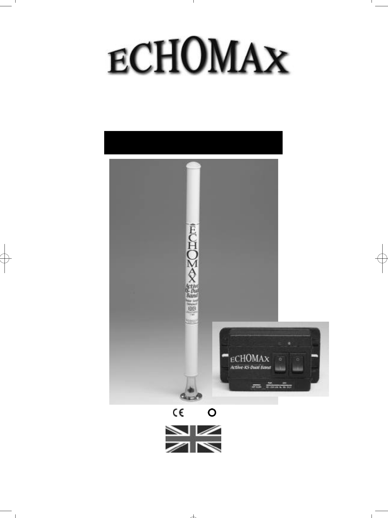
Ac t i v e- XS-D u a lBand
Radar Target Enhancer
!
GENERAL INTRODUCTION
The Echomax Active-XS-Dual Band Radar Target Enhancer (RTE) is designed to respond to interrogating both
X (9.3 - 9.5 GHz) and S band radar (2.9 - 3.1 GHz) by receiving a transmitted pulse, amplifying and re - t r a n s m i t t i n g
the pulse back to the radar at the same frequency with minimum delay, thereby improving the radar detection
range and visibility of small targets. It will not enhance significantly vessels with large radar cross section.
The Active-XS-Dual Band Radar Target Enhancer is suitable for all vessels up to 150 gross tonnage.
SOLAS V Regulation 19 2.1.7 states (Radar reflector): All ships irrespective of size shall have: if less than
150 gross tonnage and if practicable, a radar reflector, or other means to enable detection by ships navigating
by radar at both 9 GHz (X Band) and 3 GHz. (S Band). The Active-XS-Dual Band Radar Target Enhancer will
typically enhance the RCS (radar cross section) of vessels up to 25M in length. For small craft/rigid inflatables
improvements will start to be seen at around 1-2 miles extending to 8-10 miles or more depending on
prevailing conditions. The response of the RTE will vary according to range, RTE and radar height above sea
level, radar power and condition. Poor weather, sea state and precipitation will greatly reduce the response.
IMPORTANT
The fitting of the Active-XS-Dual Band RTE does
not exclude you from exercising safe navigational
judgement for your vessel under the International
Regulations for the Prevention of Collisions at Sea
and to keep a proper look out at all times
LICENSING REQUIREMENTS
Many countries and administrations require a ships
radio license or modification of your existing ships radio
licence before the Active-XS can be used for maritime
use. Contact your local administration for details.
ECHOMAX ACTIVE-XS COMPONENTS,
CONSTRUCTION, use and installation
If you are not able to safely install the unit yourself
you are advised to seek the services of a competent
person or company to install the RTE.
COMPONENTS
Echomax Active-XS mast head radome fitted with
24 meters of 3 core cable
Control box Operation manual
RADOME FITTING
The antenna has provisions in the base for a 1 inch -14
NF female thread mast fitting or deck mount bracket.
Plastic mounts should not be used. To ensure a
permanent fixing ‘LOCTITE’ or PTFE or plumbers tape
should be used and the RTE must be screwed down
tightly. Care must be taken to ensure that as the RTE is
tightened on the base the cable is allowed to turn freely.
For mast fitting the radome must be fitted vertically as
high as possible. The receive/ transmit antennas
positioned 70mm from the base of the radome must
have a clear 360 degree azimuth. It should be fitted
at least 6 inches/150mm from the mast on the offset
bracket. It should not be fitted on a back stay or where
its vision is obscured or is close to any metal object
otherwise performance could be significantly impaired.
The radome unit must never be painted as this will
seriously impair performance. The radome must not
be fitted in or close to the vessels radar vertical or
horizontal transmitting beam as this may seriously
d a m a g e the PCB. The RTE should be fitted above the
radar. It is possible to shorten the cable or extend by
a further 25 meters without affecting the p e rf o rm a n c e
using extension cable rated at 3A at 300V.
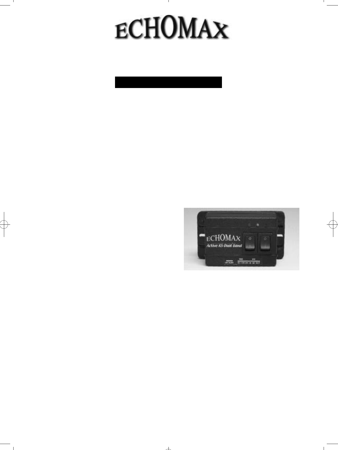
ECHOMAX CONTROL BOX for surface
fitting or flush mount with optional new
flush mount kit
Use and wiring instructions
The control box must be fitted internally as it is not
waterproof and can be wired from the base or back as
required. A 12v fused or circuit breaker supply of 3-5A
is required.
The control box has a quadruple alarm facility. Once
the red power switch is turned on the unit is in the
quiescent mode and will consume up to 23mA. When
interrogated by an X Band radar the green LED light
will flash every 2.4 seconds. If the flash lengthens then
this indicates that more than one radar is painting
the antenna. If painted by a high speed radar which
rotates every 1.5 seconds then the LED light will flash
quicker. When painted by an S Band radar the yellow
light will flash. It should be borne in mind that vessels
with S Band radar are very large and in most cases
over 3000GT and can neither stop nor change course
quickly. Turning on the green switch will mobilize the
i n t e rnal buzzer, which is set to actuate at appro x i m a t e l y
half a second intervals. The control box also has
facilities for a 8A external volt free alarm. THIS IS NOT
A POWER SOURCE and must be initialised as shown
in the wiring diagram. The control box has an
externally replaceable 2 Amp fuse and is surge and
cross polarity protected.
All radars emit irregular vertical side lodes (spikes)
and should the Active-XS be installed in the path of a
spike it will think that it is being painted by another
ships radar. Movement of the Active-XS radome to
another position may remedy this, if not, the ships
radar will need to be switched off. Identical radar may
have a different side lobe pattern.
Ac t i v e- XS-D u a lBand
Radar Target Enhancer
Ac t i v e- XS-D u a lBand
Radar Target Enhancer
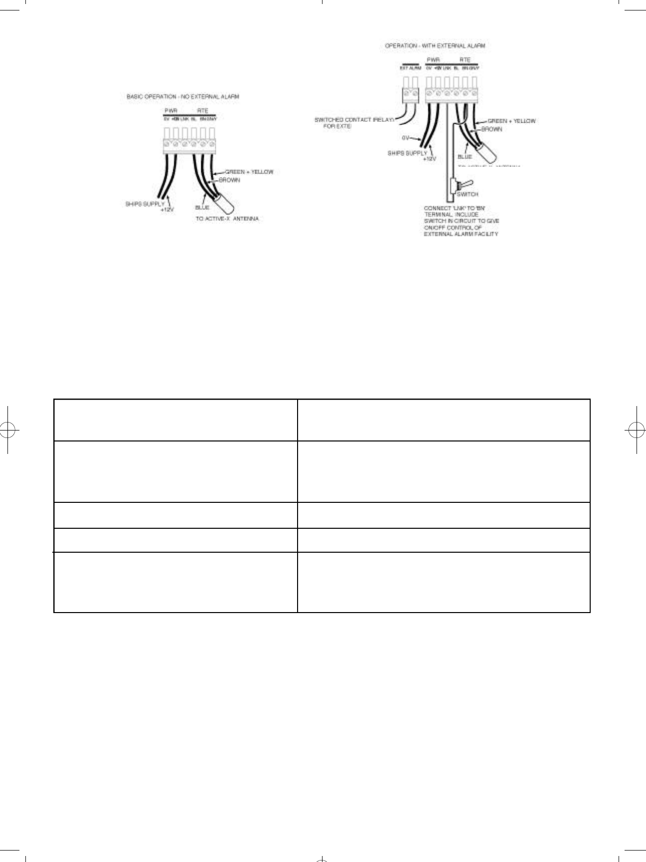
RTE CONNECTIONS
The diagrams show the correct wiring installation
PERFORMANCE CHECK
As the RCS of your vessel may exceed the RCS of the RTE, the trial is best carried out at 0.5 nm as the target
can be easily identified. The range should then be increased at intervals of 0.5 nm and the RTE switched on and
off noting the change in response. As the range increases the bare target will not be seen and whilst moving the
RTE is left on so that the test target can be seen at all times. This is important in busy waters to avoid confusion
with other vessels.
If the target is lost it can be acquired by turning the RTE on and off and watching the display for change in
target response. In normal weather and sea conditions, with RTE and interrogating radar mounted at four meters
above sea level should respond on the radar screen as shown below. If the mounting heights, including that of the
interrogating radar vary so will the response due to curvature of the earth. These figures are for guidance only and
should not be relied upon.
2KW radar up to 4 nm : 5KW radar up to 10 nm : 10-25KW radar up to 15-20 nm
FAULT FINDING CHART
No Red LED light when red switch Check fuse or circuit breaker
is turned on Check polarity of wiring
Check power supply at control box
Damaged cable or wrong connection
Unit switched on and continuous green Local radar on, or radar operating moored nearby (<15M)
LED light shows, in harbour or when Moored close to large metal object
saturating RTE Check polarity of radome wiring
Being actuated by ships own radar – turn off radar and if
necessary relocate Active-X
Relocate vessel to more suitable position
Unit on and buzzer on and unit fails to Check all above faults. Is RTE in shadow of
operate when it clearly is interrogated interrogating radar as it will not operate if masked
Buzzer switched on but does not sound Buzzer faulty – return control box to Echomax
when painted by radar for inspection
Green LED light or alarm sounds when ships own
radar is switched on
Radars emit irregular vertical side lodes (spikes) and should
the Active-XS be installed in the path of a spike it will think
that it is being painted by another ships radar. Movement of
the Active-XS radome to another position may remedy this, if
not the ships radar will need to be switched off. Identical radar
may have a different side lobe pattern.
DIMENSIONS and WEIGHTS
Reception frequency: X Band Radar 9.3 - 9.5 GHz
S Band Radar 2.9 - 3.1 GHz
Operating Temperature: - 20 to + 60 degrees C
Voltage: 12V DC - + 30% - 10%
(voltage surge and cross
polarity protected)
Current consumption
in quiescent state: <23mA
Current consumption X Band Radar 190mA
when transmitting S Band Radar 155mA
typically:
Position accuracy: Within 1 metre
EIRP: 1W (typically) Exceeds ISO 8729-2 effective July 09 - X Band Radar
7.5m2and S Band Radar 0.5m2at Zero, +/-10 and 20
degrees of heel maintained over a total angle of 280
degrees.
continued overleaf
Antenna length: 685mm
Antenna width: 40.5mm
Antenna weight: 573gms (excluding cable)
Control Box width: 92mm
Control Box height: 51mm
Control Box depth: 38mm
Control Box weight: 99gms
Cable length: 24m 3 core 0.5mm2
Cable weight: 967gms
TECHNICAL SPECIFICATION
STATED PERFORMANCE LEVEL SPL
TOACTIVEXSANTENNA
GUARANTEE
The Echomax Active-XS-Dual Band RTE is guaranteed
for 12 months from the date of purchase and provides
for the complete replacement at our discretion of the
complete unit or any of the components providing
failure is attributed to component failure or defect
which is not attributed to accidents, misuse, fair wear
or tear or neglect.
The guarantee is invalidated by any attempt
w h a t s o e v e r to open up or interfere in any way with
the unit.
It is the users responsibility to return the unit at his
expense to us to inspect and report on the reason
for failure. No exchange unit will be given until a full
inspection and report is issued.
This guarantee does not affect your statutory
consumer rights or those governed by local Law.
For comparison with competing products see
www.echomax.co.uk.
Declaration of Conformity
(As required by Article 6.3 of Directive 1999/5/EC-
RTTE Directive)
Declares under his sole responsibility that the active
radar target enhancer manufactured by:
AQUAMATE PRODUCTS LTD.
also trading as ECHOMAX
PO Box 6032
Dunmow
Essex CM6 3AS U.K.
Telephone + 00 44 (0) 1371 830216 Fax 831733
Email: echomaxsales@aol.com
Intended for Worldwide use as an S and X Band active
radar target enhancer aboard non SOLAS vessels and
identified by the type number Active-XS to which this
declaration refers has been tested to the essential
radio, EMC & safety test suites required by the notified
body and is in conformity with the standards
EN 302 752 V1.1.1 (2009-02)
EN 60945: 2002 (Clauses 9, 10 & 12)
And complies with the essential requirements of
Directive 1999/5/EC
Conformity procedure under Annex IV of 1999/5/EC
(Technical Construction File) has been undertaken by
QinetiQ (0191) of Cody Technology Park, Ively Road,
Farnborough GU14 0LX UK
The Technical Construction File is held by:-
John H Simpson
AQUAMATE PRODUCTS LTD.
also trading as ECHOMAX
PO Box 6032
Dunmow
Essex CM6 3AS UK
Tel: +00 44 (0)1371 830216 Fax 831733
Email: echomaxsales@aol.com
Signed ………………………………………
John H. Simpson
Managing Director
May 2010
EMAXSM UK 06/10
Typical performance – QinetiQ Funtington Anechoic
Chamber March 2010
X BAND RADAR SPL S BAND RADAR SPL
(ISO Standard 7.5m2) (ISO Standard 0.5m2)
Zero degrees: 118.33m2Zero degrees: 6.26m2
+/- 10 degrees: 65.07m2+/- 10 degrees: 6.44m2
+/- 20 degrees: 19.49m2+/- 20 degrees: 5.36m2
NB. Production units will have the following
S Band SPL
Zero degrees: 15.75m2
+/- 10 degrees: 16.20m2
+/- 20 degrees: 13.40m2
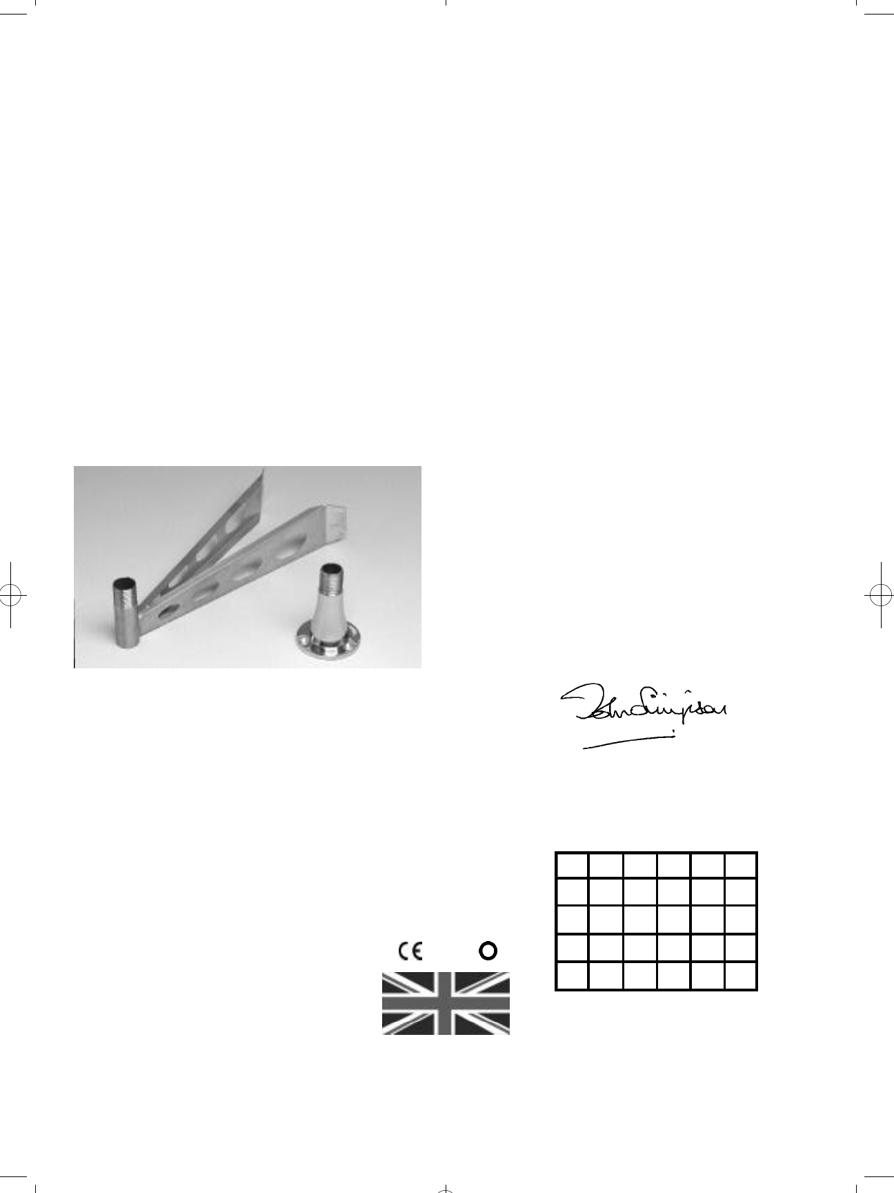
OPTIONAL FITTINGS
Base fitting: female 1 inch – 14 NF thread
Mast Bracket:
26cm reach and
female 1 inch – 14 NF thread
Flush Mount Kit for Control Box
Manufactured by
Echomax Products in the UK
PO Box 6032, Dunmow CM6 3AS, UK.
Email: echomaxsales@aol.com www.echomax.co.uk
Tel: 00 44 (0)1371 830216 Fax: 831733
!
AT BE BG CY CZ DK
EE FI FR DE GR HU
IS IE IT LV LT LU
MT NL NO PL RO SK
SI ES SE CH LI GB
Specifications given in this manual are subject to change
without notification.
Production units comply with:
EN 302 752 V1.1.1. (2009-02)
EN 60945: 2002 (Clauses 9, 10 & 12)
Complies with essential requirements of R & TTE
Directive 1999/5/EC. CE 0191: Performance
requirements of ISO 8729-2 X and S Band Radar.