Arcade Hammer Dx Manual User
2013-11-19
User Manual: Arcade Hammer Dx Manual
Open the PDF directly: View PDF ![]() .
.
Page Count: 61

3
PRECAUTIONS FOR USE
Be sure to read the following
The following safety precautions are given throughout this manual. They must be strictly followed to protect those
who install, use or maintain this product as well as to protect players, visitors and property.
For safty reasons.
• The following suggestions should be adhered to:
• The following graphic suggestions describe the types of precautions to be followed.
• Precautions to be followed:
CAUTION
Disregarding could result in injury or product damage.
WARNING
Disregarding could result in serious injury.
Indicates a matter which must be performed.
Indicates a care should be taken.
Certain procedures require a qualified in-shop maintenance person or industry specialist. For such
instructions, a qualified person must take care of the jobs.
•
Otherwise an electric shock, machine trouble, or a serious accident may result.
•
Replacing the machine parts, inspecting and maintaining the machines, and troubleshooting must be assigned only
to a qualified in-shop maintenance person or industry specialist. This booklet gives instructions that hazardous jobs in
particular must be handled by an industry specialist. Qualified in-shop maintenance person and industry specialist are
defined as follows.
Qualified in-shop maintenance person
•
A service staff shall have experience in operations of game machines. The staff shall be responsible for assembly,
installation, inspection and maintenance of the machine.
Industry specialist
•
An industry specialist must be engaged in designing, manufacturing, inspecting and servicing amusement machines.
He or she must have an education in electrical, electronic and mechanical engineering, and routinely maintain and
repair amusement machines.
Forbidden.
4
PRECAUTIONS FOR USE
Setting Up
Be sure to consult an industry specialist when setting
up, moving or transporting this product.
•
This product should not be set up, moved or transported
by any one other than an industry specialist.
•
When installing this product, set the 4 leg levelers evenly
on the floor and make sure that the product is installed
stably in a horizontal position. Unstable installation may
result in injury or accident.
•
When installing this product, do not apply undue force on
movable parts. Otherwise, injury and accident may result,
or the product may be damaged.
The machine for indoor usage only does not
install outside.
Do not set the game machine up near
emergency exits.
Protect the game machine from:
•
Rain or moisture.
•
Direct sunlight.
•
Direct heat from air-conditioning and heating equipment,
e t c . .
•
Hazardous flammable substances.
•
Otherwise an accident or malfunction may result.
Do not place containers holding chemicals or
water on or near the game machine.
Do not place objects near the ventilating holes.
Do not bend the power cord by force or place
heavy objects on it.
Never plug or unplug the power cord with wet
h a n d s .
Never unplug the game machine by pulling the
power cord.
Be sure to use indoor wiring within the specified
voltage requirements. For extension cord, use the
specified rating or more.
Be sure to use the attached power cord.
Never plug more than one cord at a time into
the electrical receptacle.
Do not lay the power cord where people
walk through.
Be sure to ground this product.
Do not exert excessive force when moving
the machine.
For proper ventilation, keep the game machine
100mm(4″) away from the walls.
Do not alter the system related dipswitch settings.
WARNING CAUTION
5
PRECAUTIONS FOR USE
O p e r a t i o n
If there is any abnormality such as smoke,
bad smell or abnormal noise being emitted
from the machine, immediately turn OFF the
main power switch and unplug the power cord from
the receptacle to stop operating it.
•
Using the machine in abnormal conditions could result
in fire or accidents.
Do not leave the power cord plugged in
improperly or covered with dust.
•
Doing so could result in electrical shock or fire,
so inspect the power cord periodically.
CAUTIONWARNING
Do not use this product anywhere other than
industrial areas.
•
Using in a residential area or an area next to a
residential area could affect signal reception of radios,
television sets, telephones, etc..
•
Do not give shock the surface of glass products.
Do not plug or unplug the power cord with wet
hands.
In handling the power cord, follow the
instructions below.
If the power cord or power plug becomes damaged,
stop using the machine immediately and ask your
nearest dealer to replace the parts.
1. Turn OFF the main power switch.
2. Unplug the power cord from the receptacle.
3 . Contact your nearest dealer.
In case of abnormality
•
Please do not play this game if
•
When you do drinking;
•
When your physical condition is not normal;
•
When you are in pregnancy;
•
When you have on a pulse controller;
•
When you have recently experienced a cramp or fainting
away while watching TV.
•
Avoid excessive force/shock while playing/moving the
game.
•
While do games, pay attention to surrounding.
•
Do not damage the power
cord.
•
Do not bend the power
cord excessively.
•
Do not heat the power
cord.
•
Do not bind the power
cord.
•
Do not sandwich the
power cord.
•
Do not modify the power
cord.
•
Do not twist the power
cord.
•
Do not pull the power
cord.
•
Do not stand on the power
cord.
•
Do not drive a nail into the
power cord.
6
PRECAUTIONS FOR USE
Inspection and cleaning
Moving and transportation
CAUTIONWARNING
Components in the game are sensitive to
vibrations and impact. Care should be used
when moving and transporting the game
machine.
Be sure not to let the machine tip over.
Before moving the machine, be sure to turn
OFF the main power switch, unplug the
power cord from the receptacle and remove
the power cord form the machine.
Before moving take the machine, off the levelers and
move it on the casters.
Avoid excessive force while moving the machine.
PRECAUTIONS
IN HANDLING
•
When setting up, inspecting, maintaining, moving or
transporting this product, follow the procedures and
instructions set forth in this manual and perform such
work safely.
•
Do not set up, handle, inspect, maintain, move or
transport this product under conditions equivalent to
the condition of "WARNING" or "CAUTION" specified
in this manual.
•
If a new owner is to have this product as a result of
transfer, etc., be sure to give this manual to the new
owner.
Be sure to turn OFF the main power switch
and unplug the power cord from the
receptacle before inspecting or cleaning the
machine.
When replacing parts, be sure to use parts of
the correct specifications. Never use parts
other than the specified ones.
Opening inside the machine shall be done by
machine specialist only as high electric
current is being sent inside. For game machine with
monitor, a care should be taken while opening its
back door. If not, a damage to the inside parts or the
monitor may occur.
If the sub power switch of the service panel
is turned OFF without turning OFF the main
power switch of the power supply unit, some
parts in the units remain live. When opening the
back door, be sure to turn OFF the main power
switch and unplug the power cord from the
receptacle.
Strictly refrain from disassembly and repair
of parts which are not indicated in this
manual, as well as settings and remodeling.
To clean the game machine, wipe it with a soft cloth
dampened in a neutral detergent.
•
Using thinner of other organic solvent or alcohol may
decompose the material.
•
Electrical shock or equipment failure could be caused
by water entering the inside of the machine.
7
CONTENTS
1. SPECIFICATION AND DIMENSIONS
1-1. DIMENSIONS………………………………………………………………………………………8
1-2. SPECIFICATIONS ………………………………………………………………………………8
2. NAME OF PARTS
2-1. EXTERNAL PARTS ………………………………………………………………………………9
2-2. INTERNAL PARTS ………………………………………………………………………………9
2-2-1. COIN DOOR AND MONITOR CONTROLER…………………………………………1 0
2-2-2. SMPS AND TRANSFORMER …………………………………………………………1 0
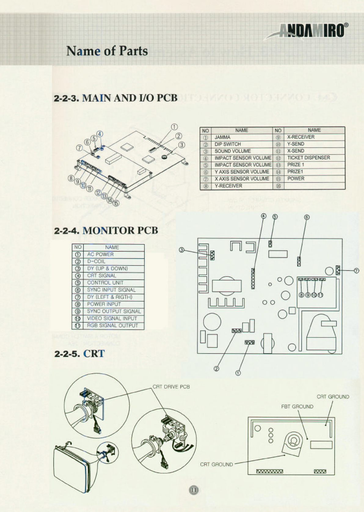
2-2-3. MAIN AND I/O PCB ……………………………………………………………………1 1
2-2-4. MONITOR PCB …………………………………………………………………………11
2-2-5. CRT…………………………………………………………………………………………1 1
3. HOW TO ASSEMBLE
3-1. CONNECTOR CONNECTION …………………………………………………………………1 2
3-2. CABINET ASSEMBLY …………………………………………………………………………1 3
4. GAME SETUP AND TEST MODE …………………………………………………… 1 4 ~ 1 5
5. DETAILS OF SETUP MODE
5-1. SETUP 1 ……………………………………………………………………………………1 6 ~ 1 7
5-2. SETUP 2 ……………………………………………………………………………………1 8 ~ 1 9
5-3. SETUP 3 (ONLY FOR THE TICKET MODE) ………………………………………………2 0
5-4. LOAD DEFAULT…………………………………………………………………………………2 1
5-5. SCREEN TEST …………………………………………………………………………………2 2
5-6. SENSOR SETTING ……………………………………………………………………………2 3
5-7. DATA BANK ……………………………………………………………………………………2 4
5-8. DATA BANK CLEAR……………………………………………………………………………2 5
6. A/S MODE
6-1. SENSOR PROBLEM ………………………………………………………………………2 6 ~ 2 7
6-2. MODE FOR CHECKING CAPSULE DISPENSER ASS'Y …………………………… 2 8 ~ 2 9
6-3. MODE FOR CHECKING THE TIKCET DISPENSER ………………………………… 3 0 ~ 3 1
7. TROUBLE SHOOTING
7-1. CHECK POINTS IN CASE OF NO VIDEO AND NO SOUND………………………………3 3
7-2. CHECK POINTS IN CASE OF NO VIDEO……………………………………………………3 3
7-3. CHECK POINTS IN CASE OF NO SOUND …………………………………………………3 3
7-4. PROBLEMS OF CAPSULE SUPPLYER ……………………………………………………3 4
8. OPTION
8-1. TICKET DOOR OPTION ………………………………………………………………………3 5
8-2. COIN DOOR OPTION …………………………………………………………………………3 5
9. DIP S/W DESCRIPTION ………………………………………………………………………3 6
10. ASSEMBLY DRAWING AND PARTS LIST
10-1. ASSEMBLING CABINET LOW(1) …………………………………………………………3 7
10-2. ASSEMBLING CABINET LOW(2) …………………………………………………………3 8
10-3. ASSEMBLING CABINET LOW(3) …………………………………………………………3 9
10-4. ASSEMBLING CABINET LOW(4) …………………………………………………………4 0
10-5. ASSEMBLING CABINET UP(1) ……………………………………………………………4 1
10-6. ASSEMBLING CABINET UP(2) ……………………………………………………………4 2
10-7. ASSEMBLING CAPSULE DISPENSER ……………………………………………………4 3
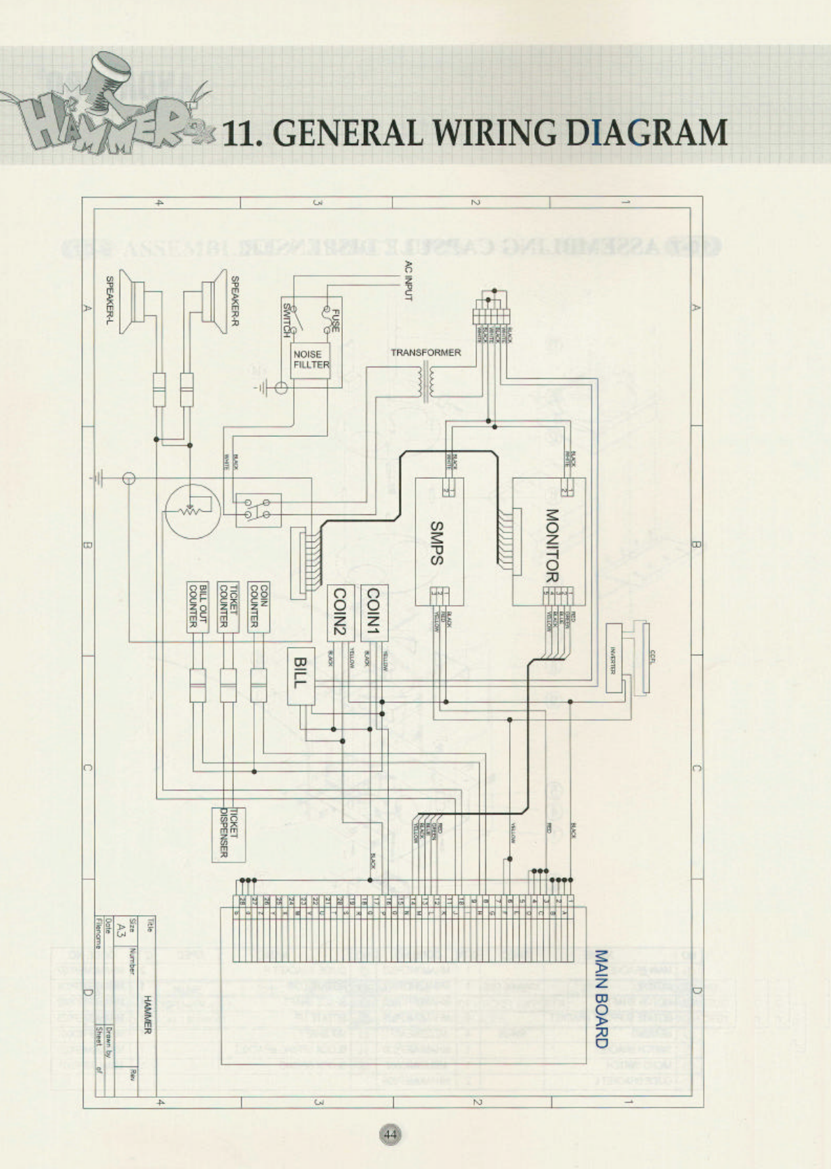
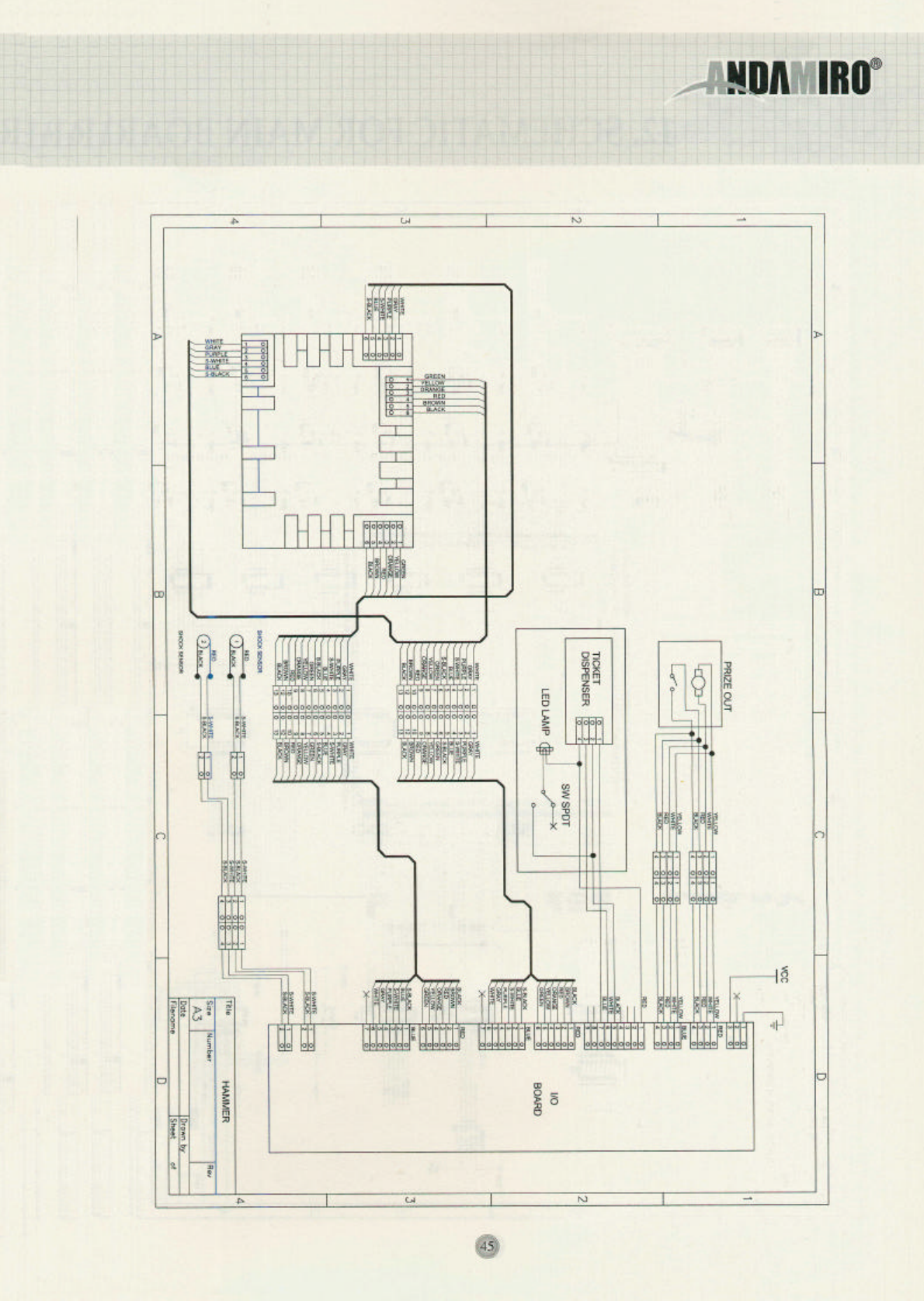
11. GENERAL WIRING DIGRAM………………………………………………………… 4 4 ~ 4 5
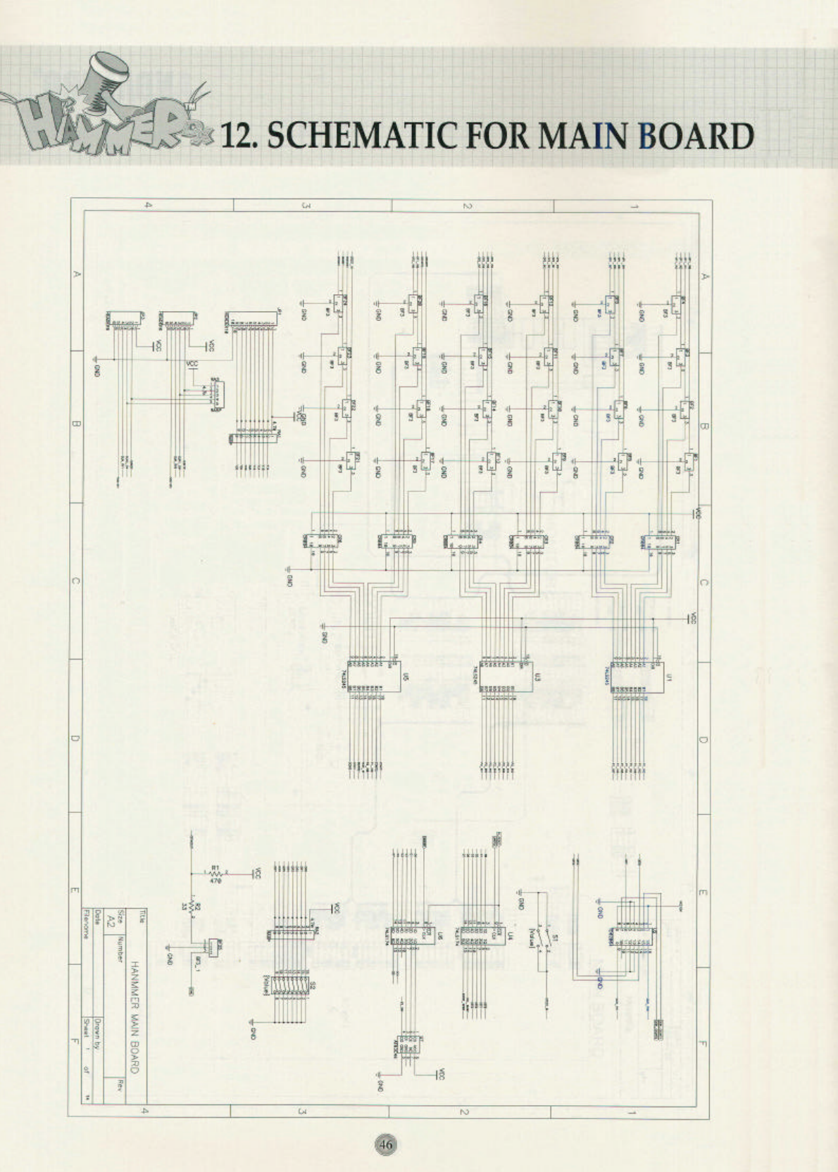
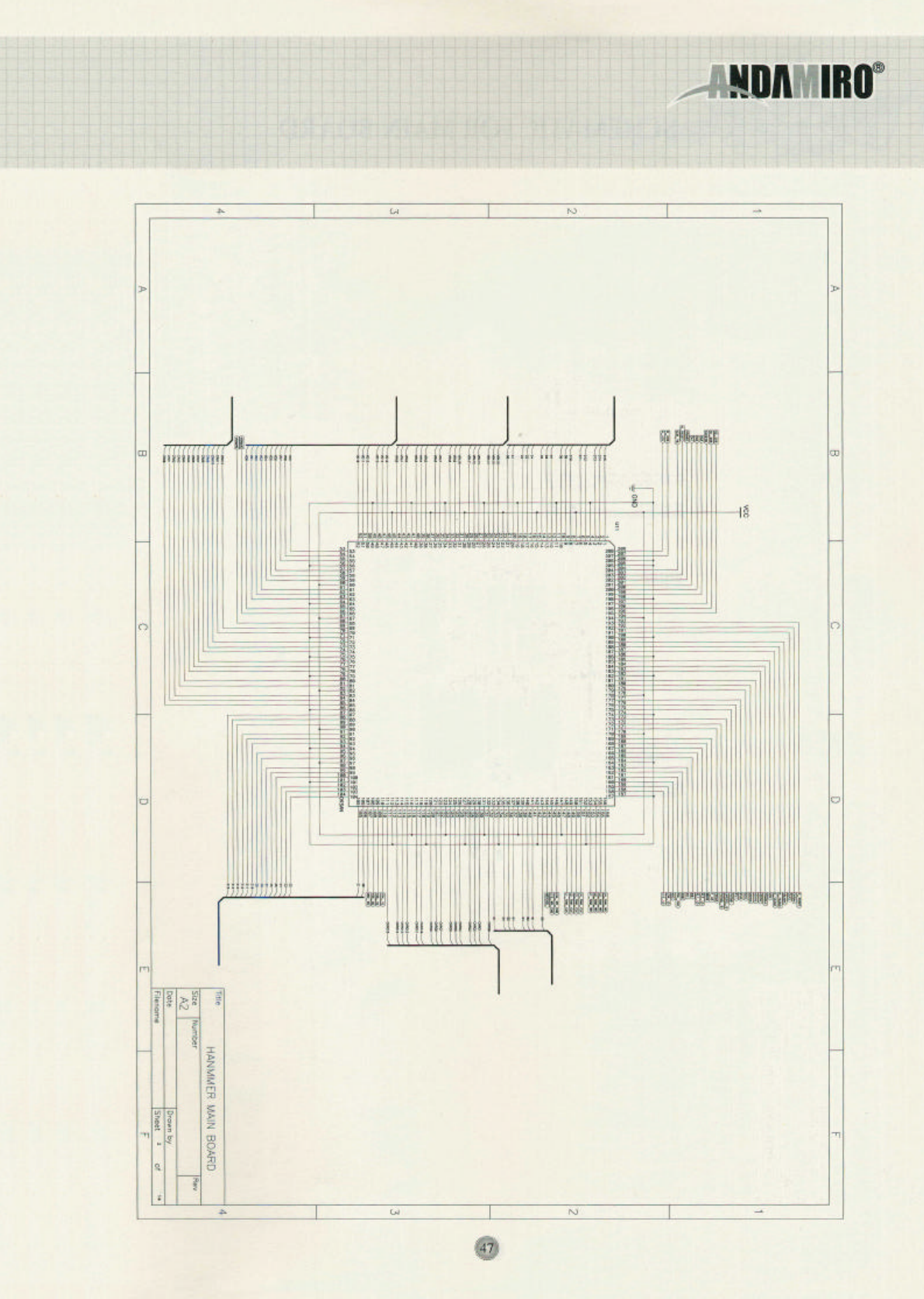
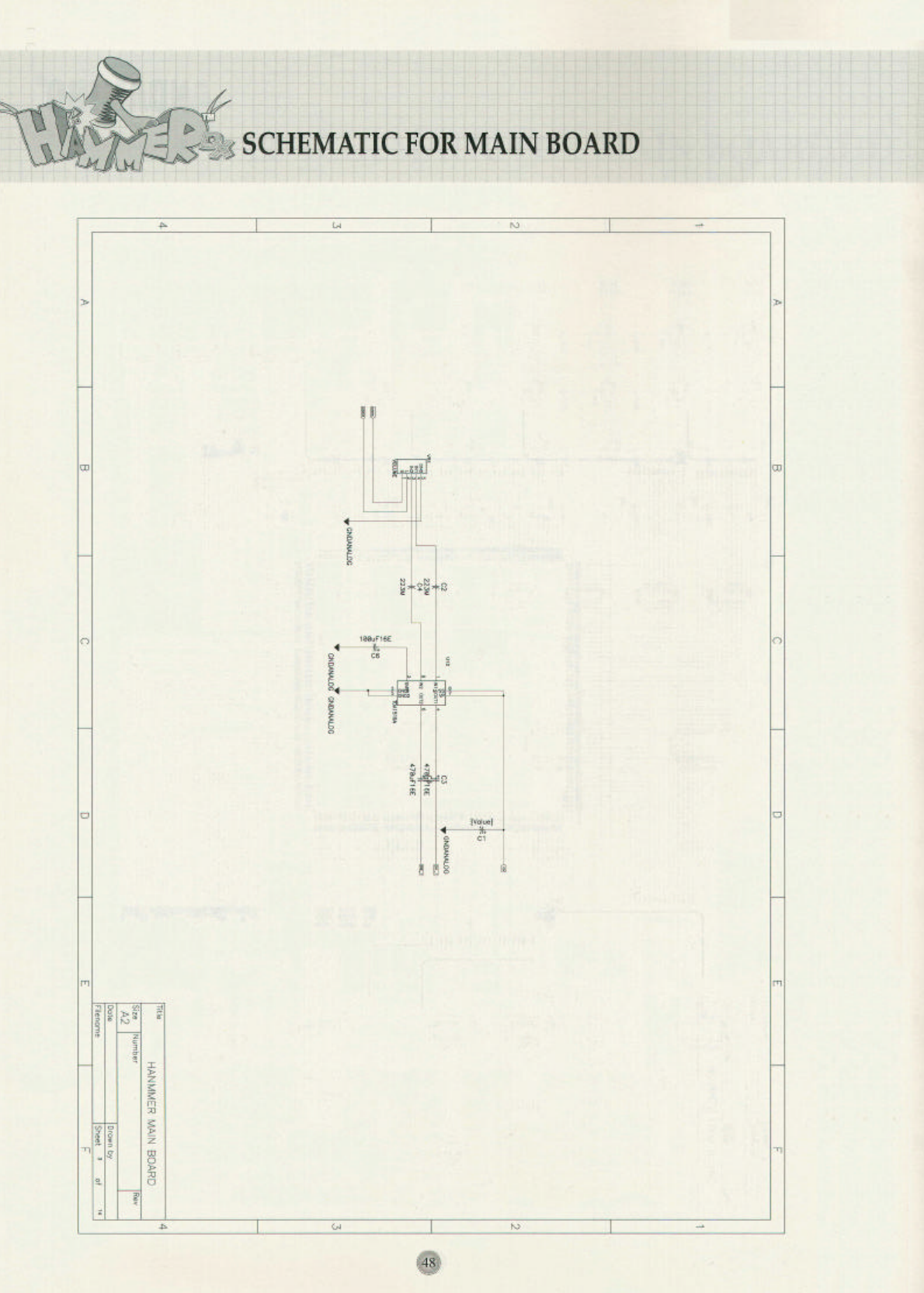
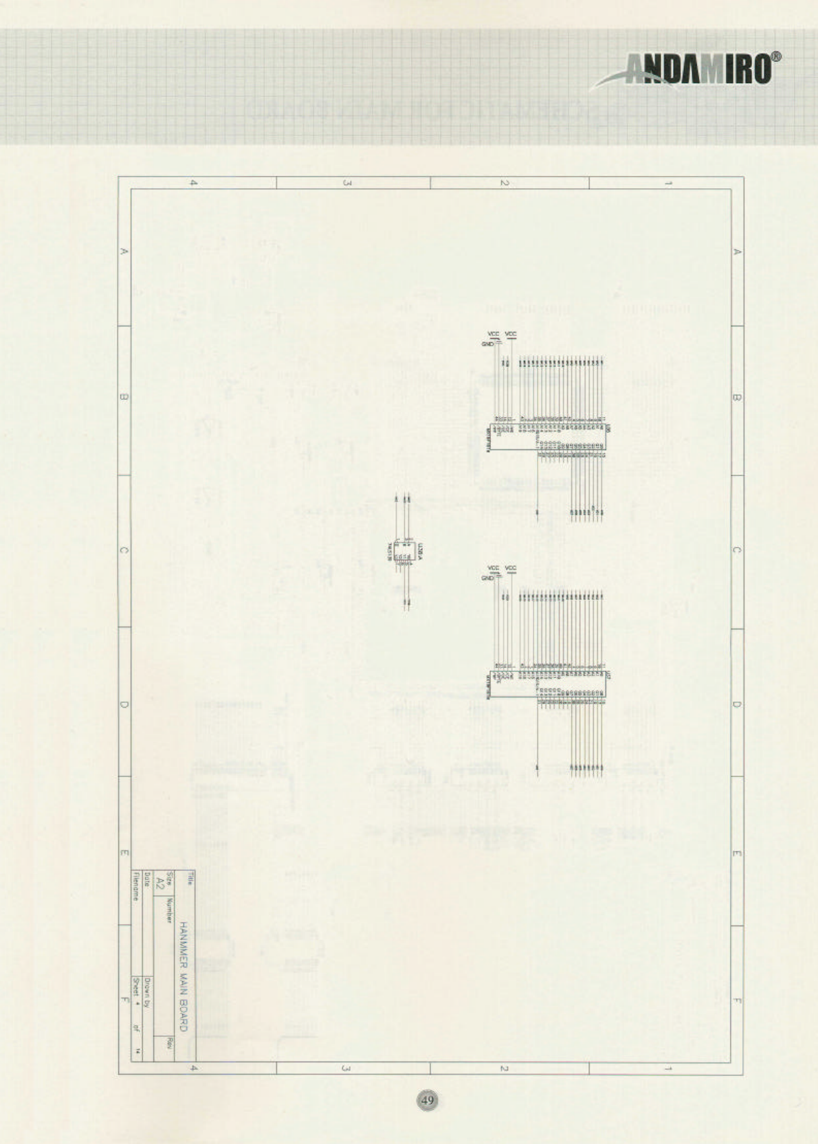
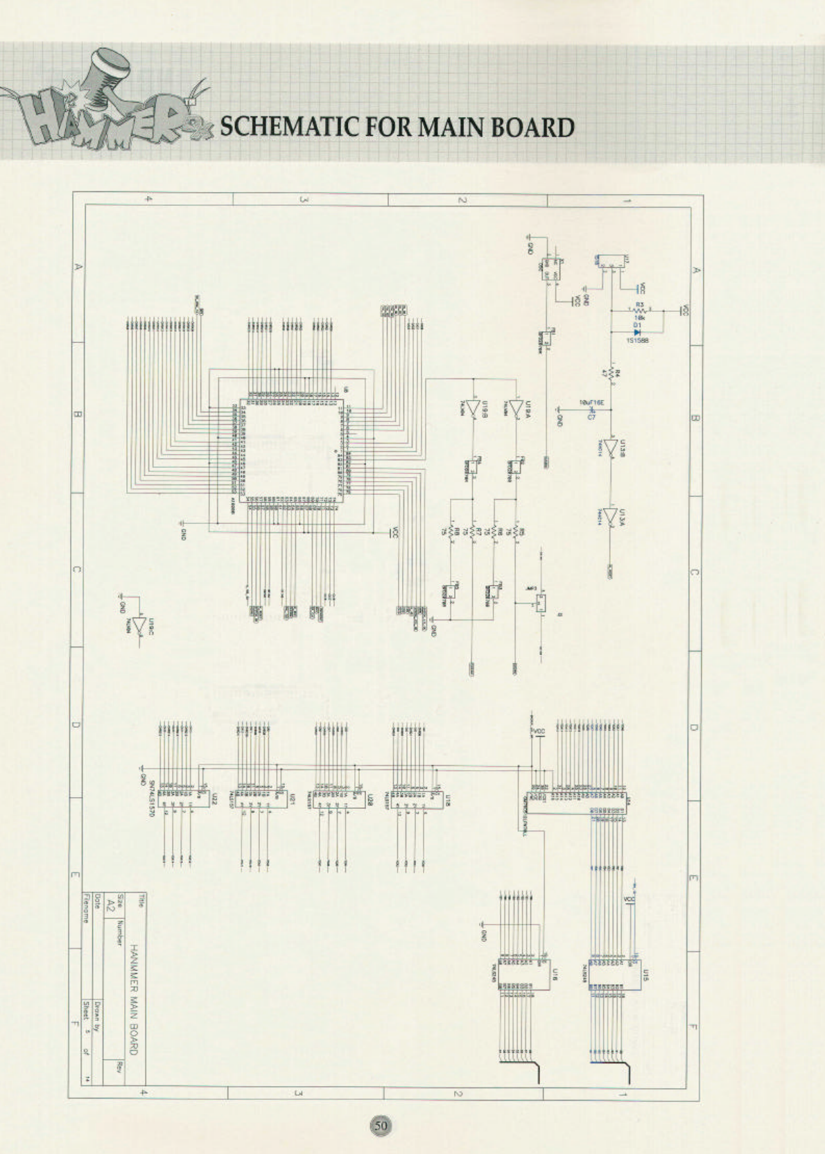
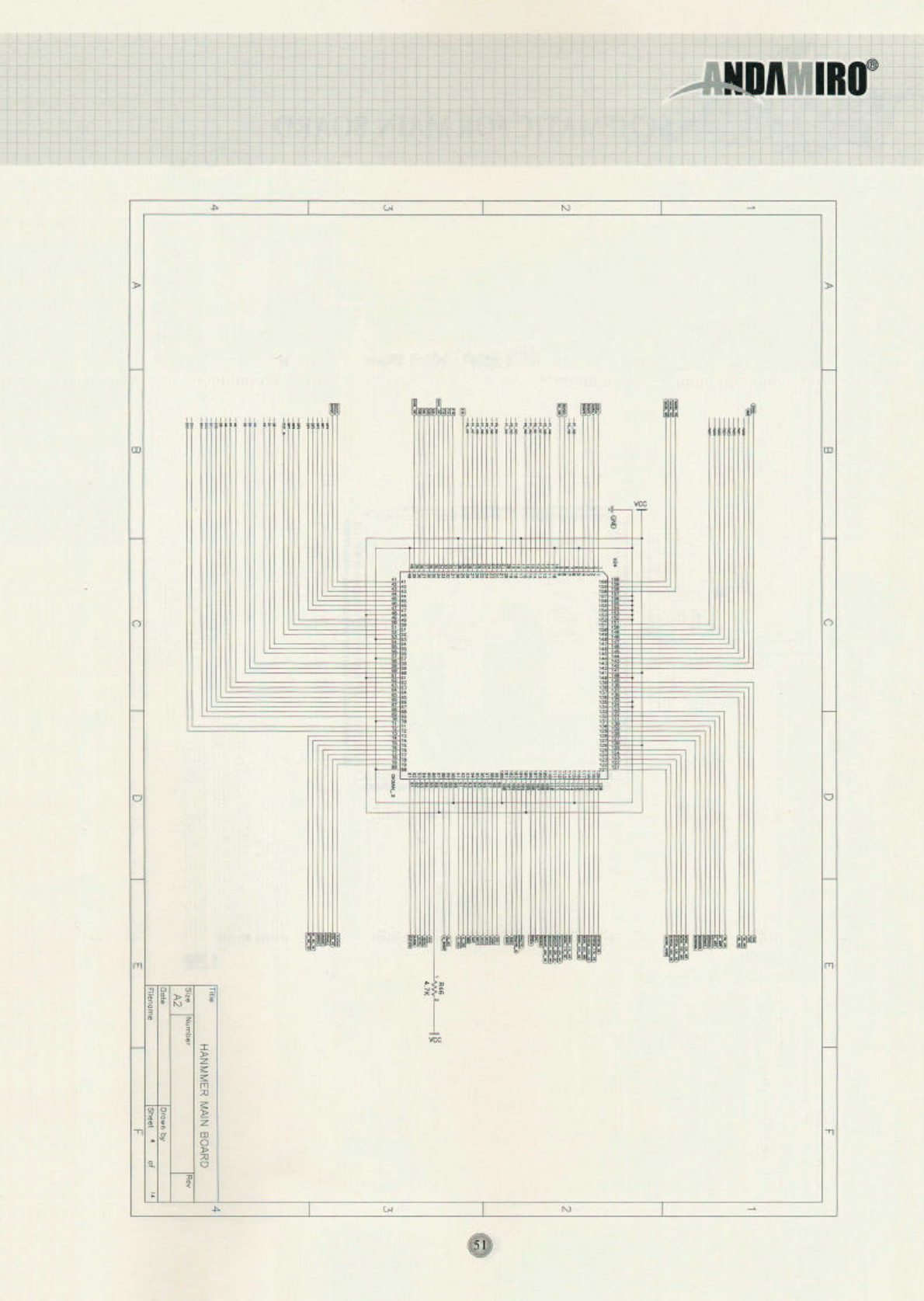
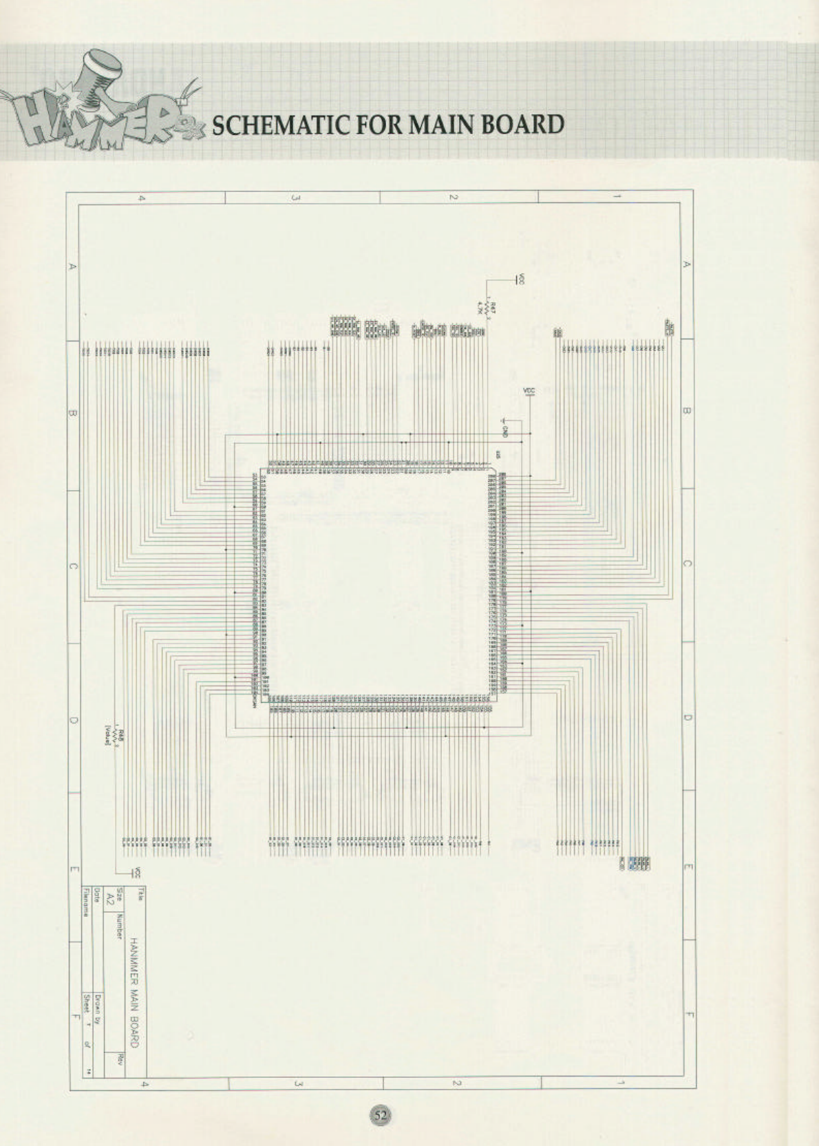
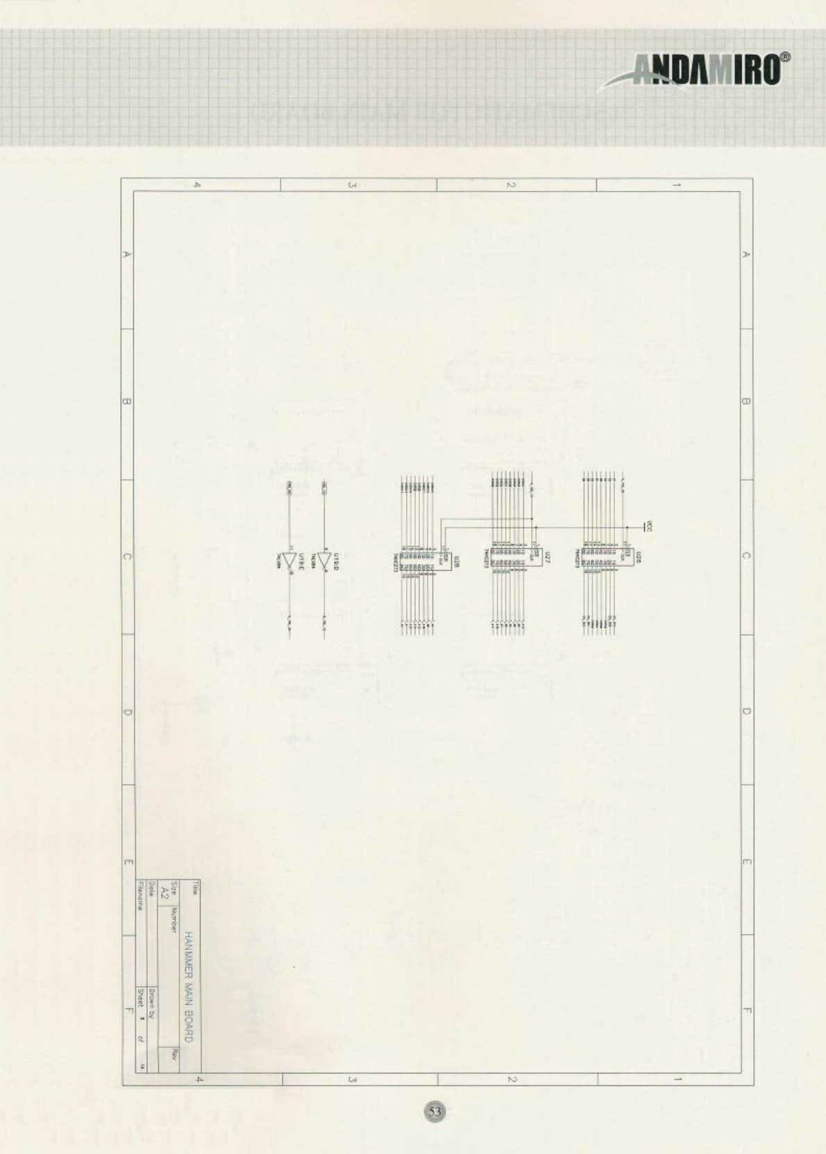
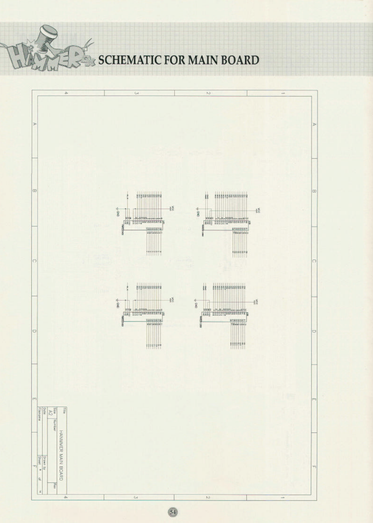
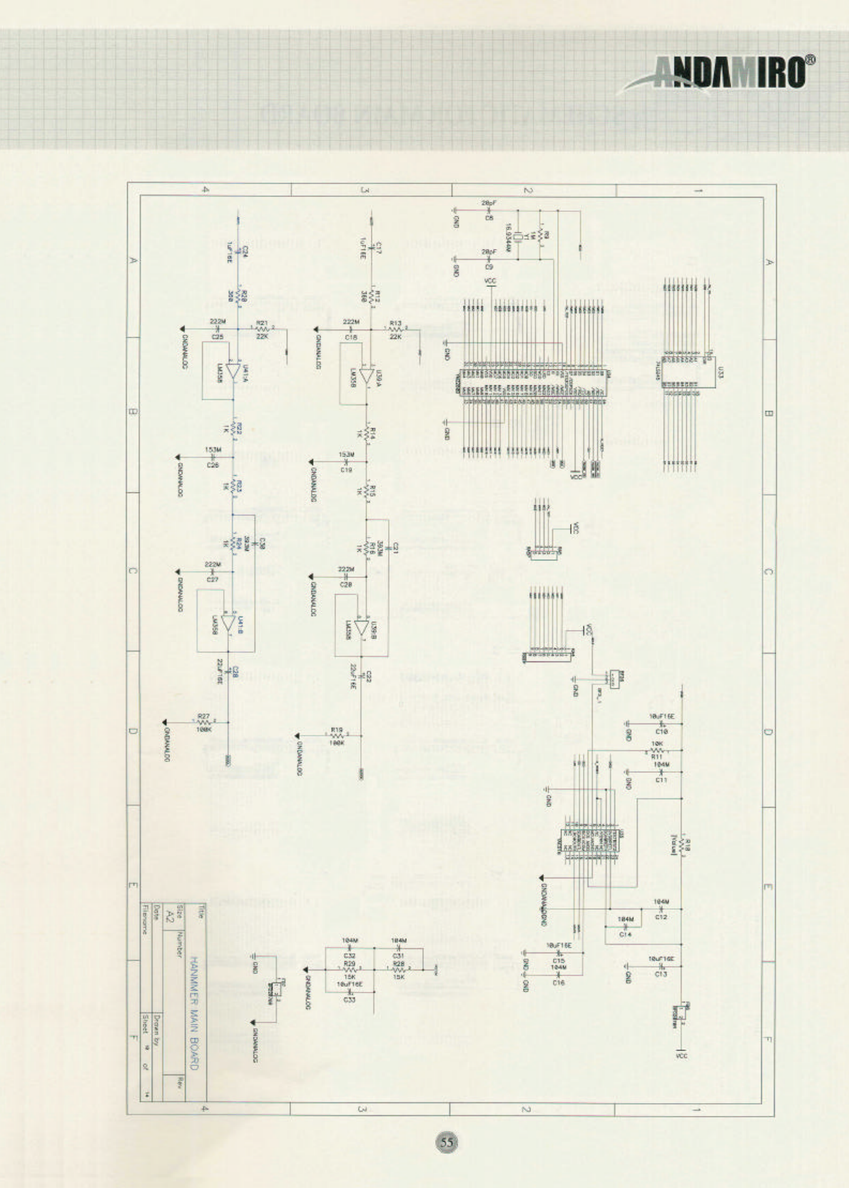
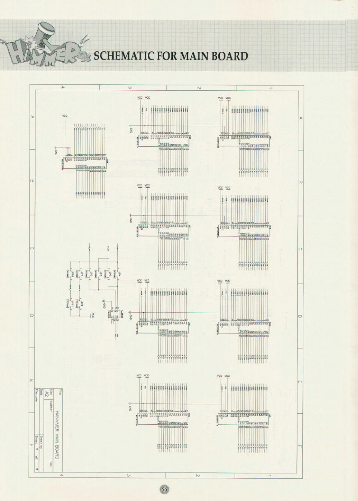
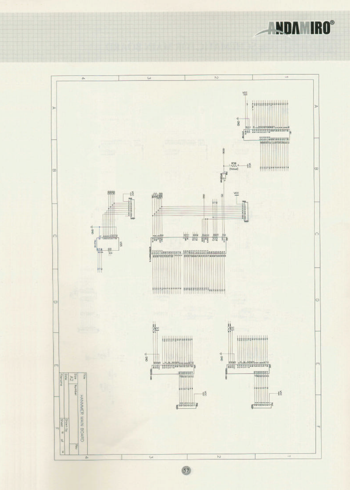
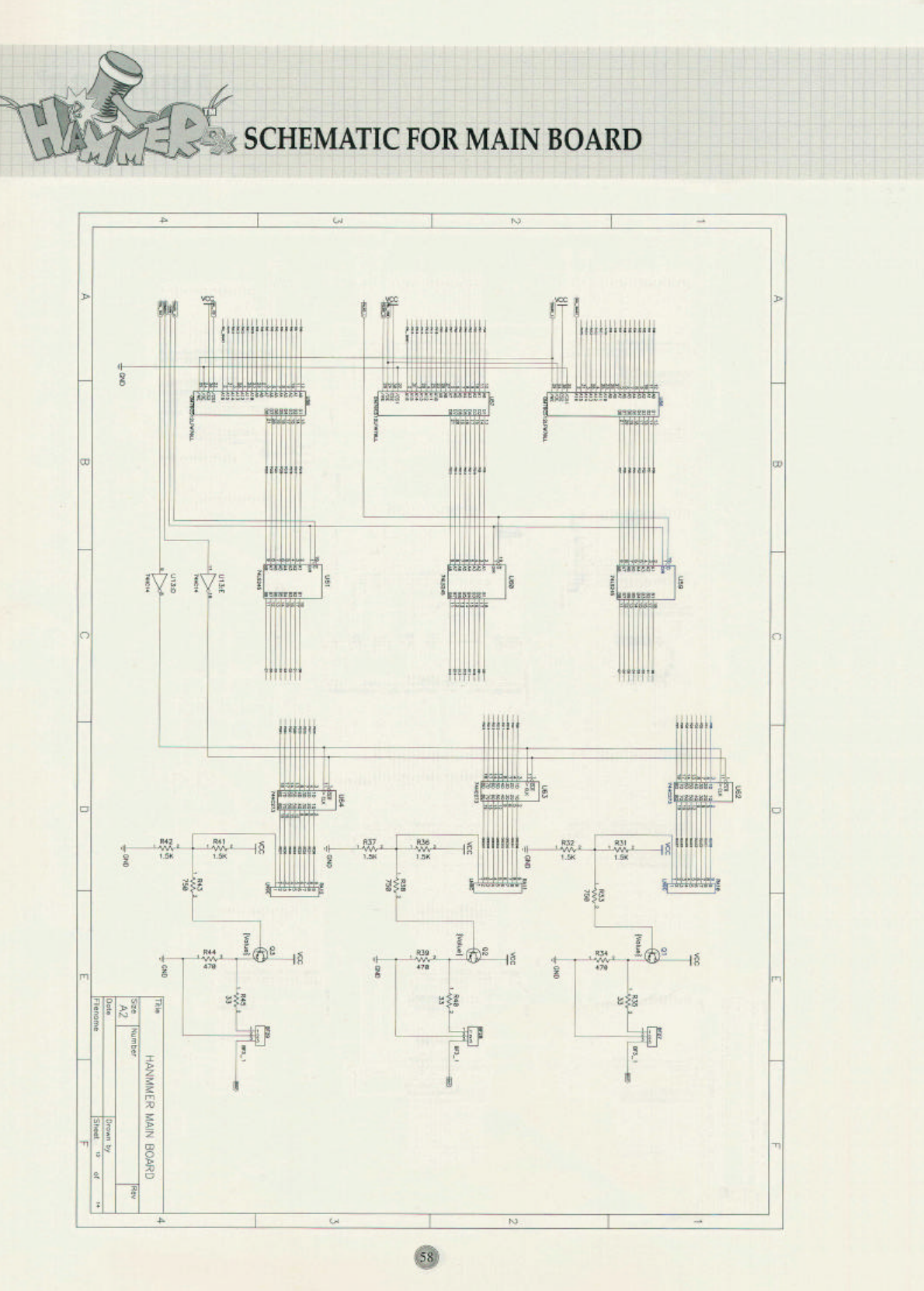
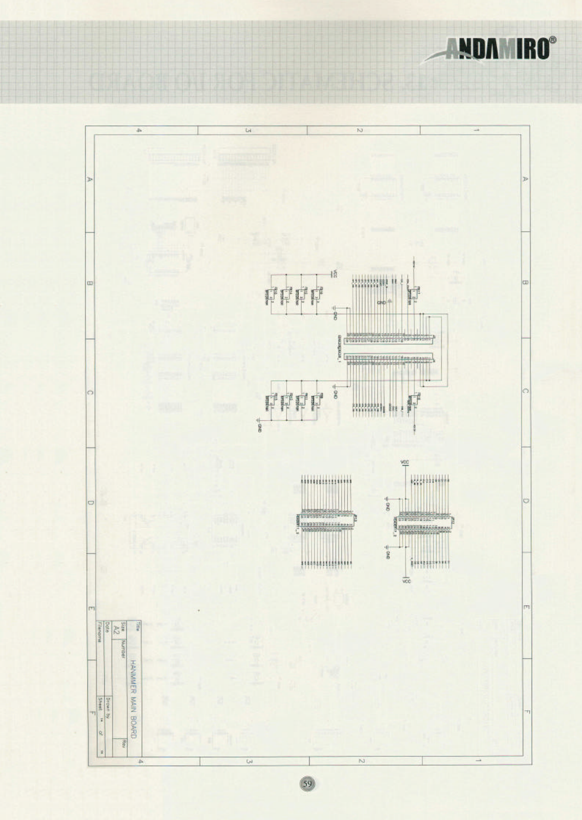
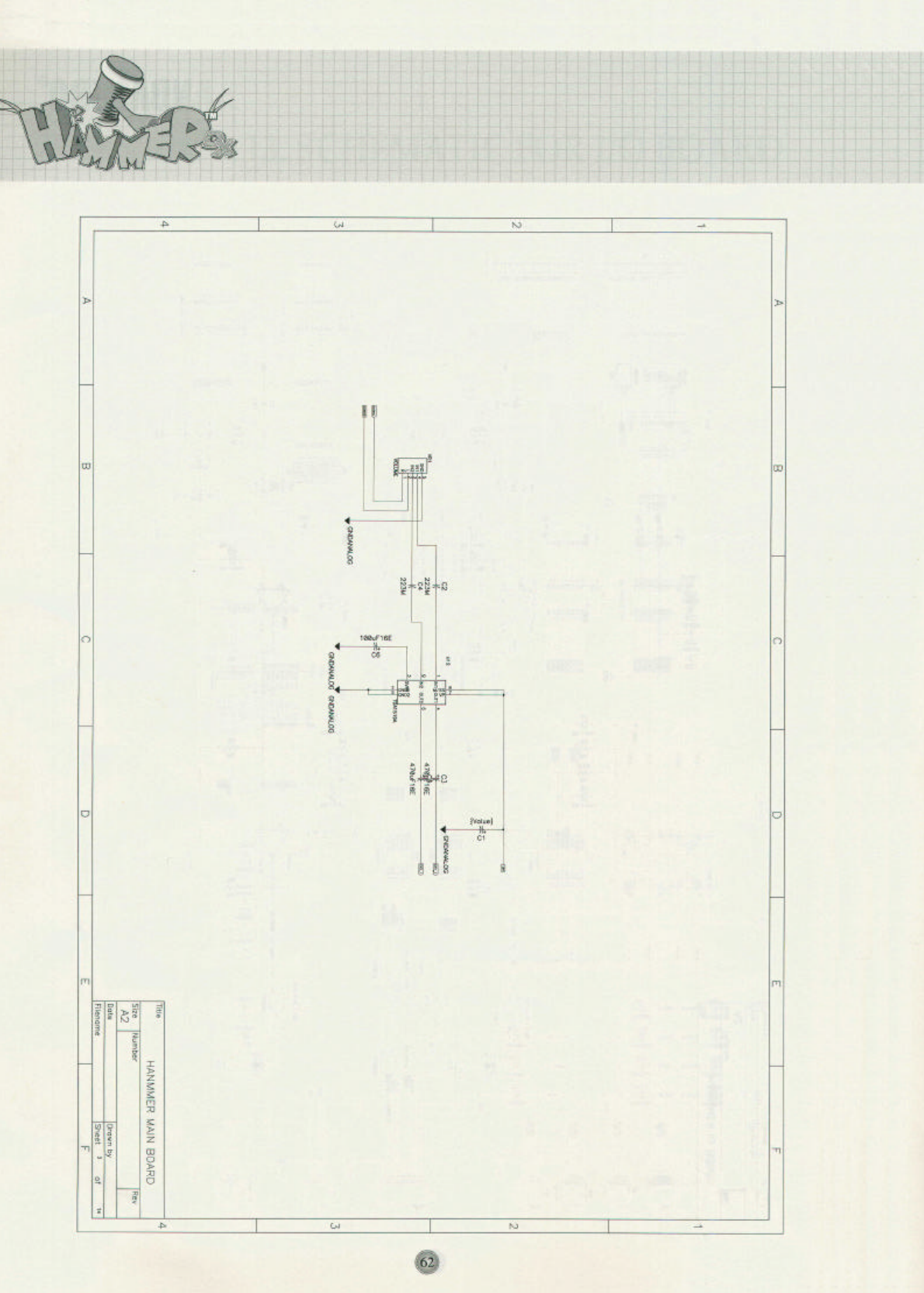
12. SCHEMATIC FOR MAIN BOARD ………………………………………………… 4 6 ~ 5 9
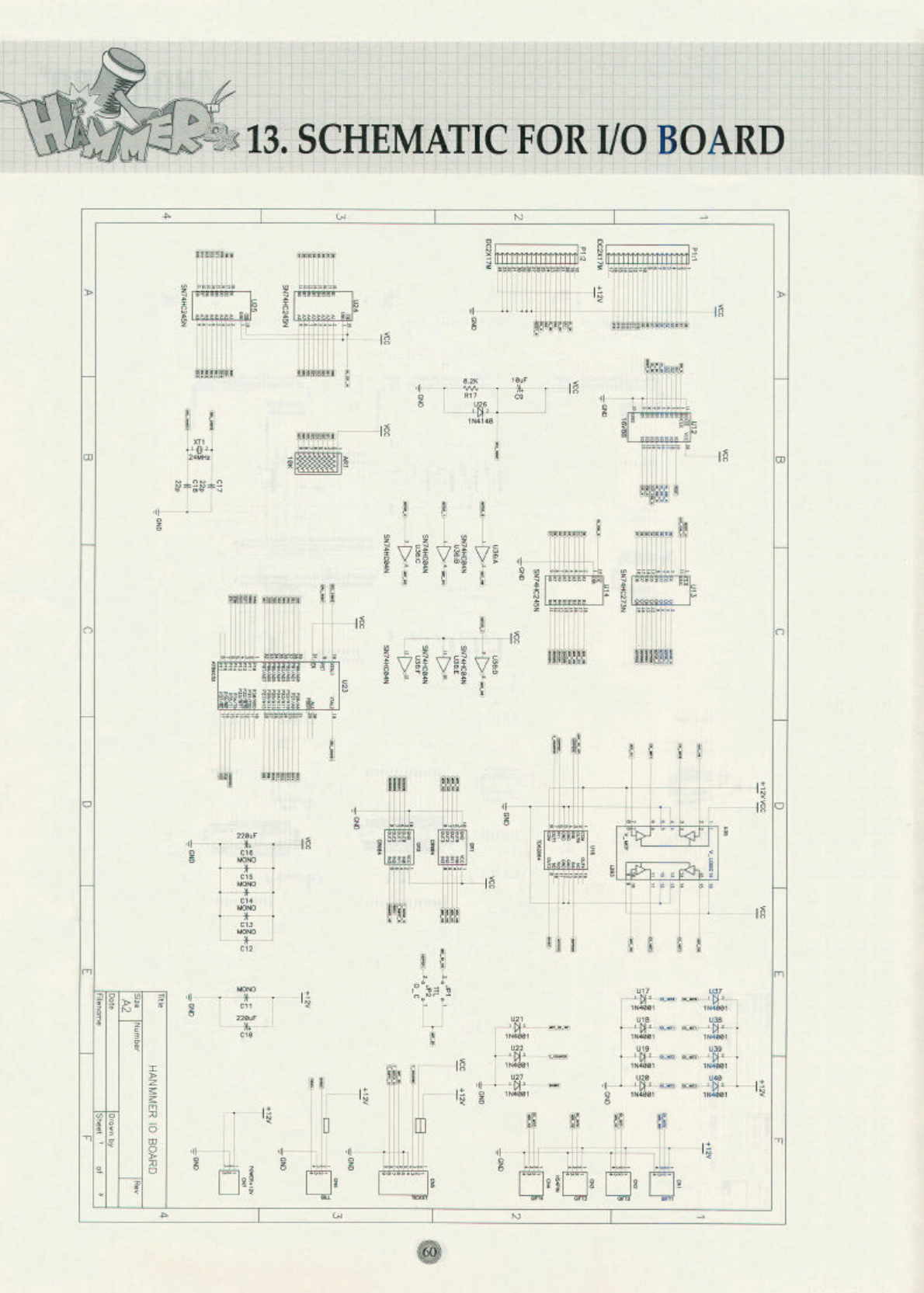
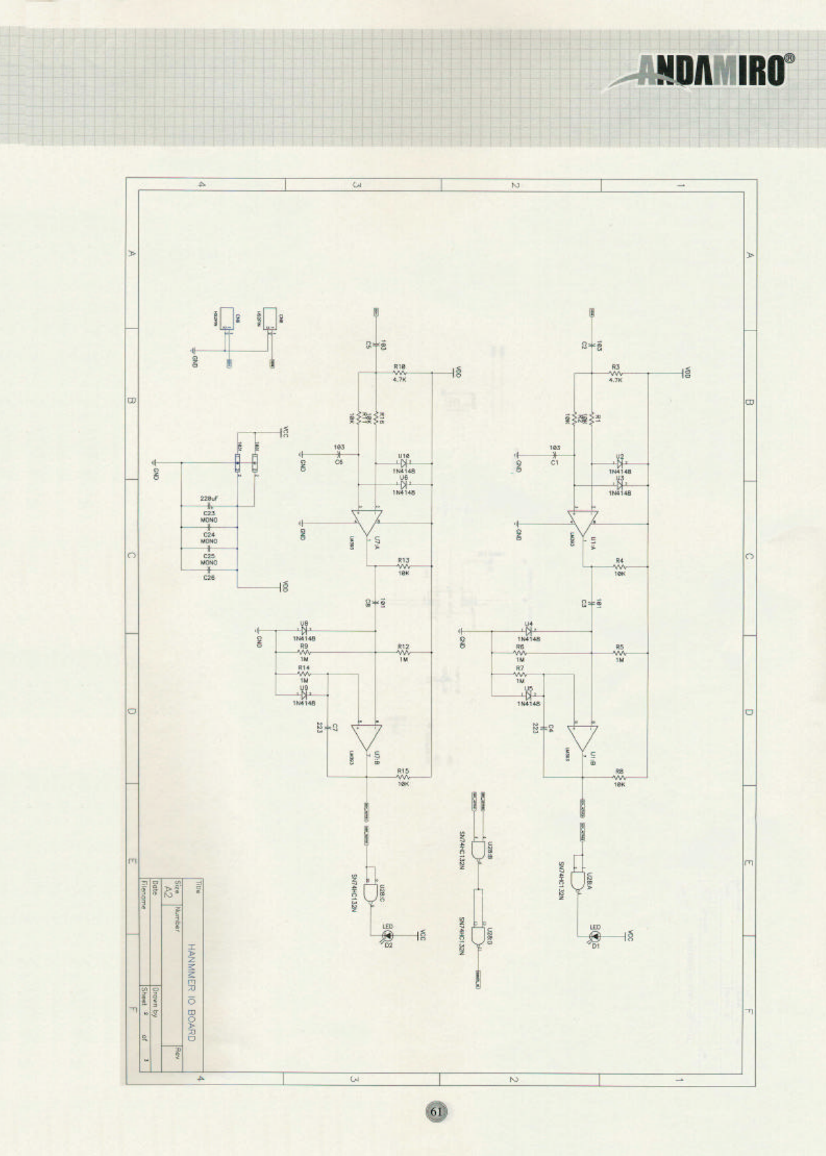
13. SCHEMATIC FOR I/O BOARD……………………………………………………… 6 0 ~ 6 2
14. SCHEMATIC FOR MONITOR BOARD………………………………………………… 6 3
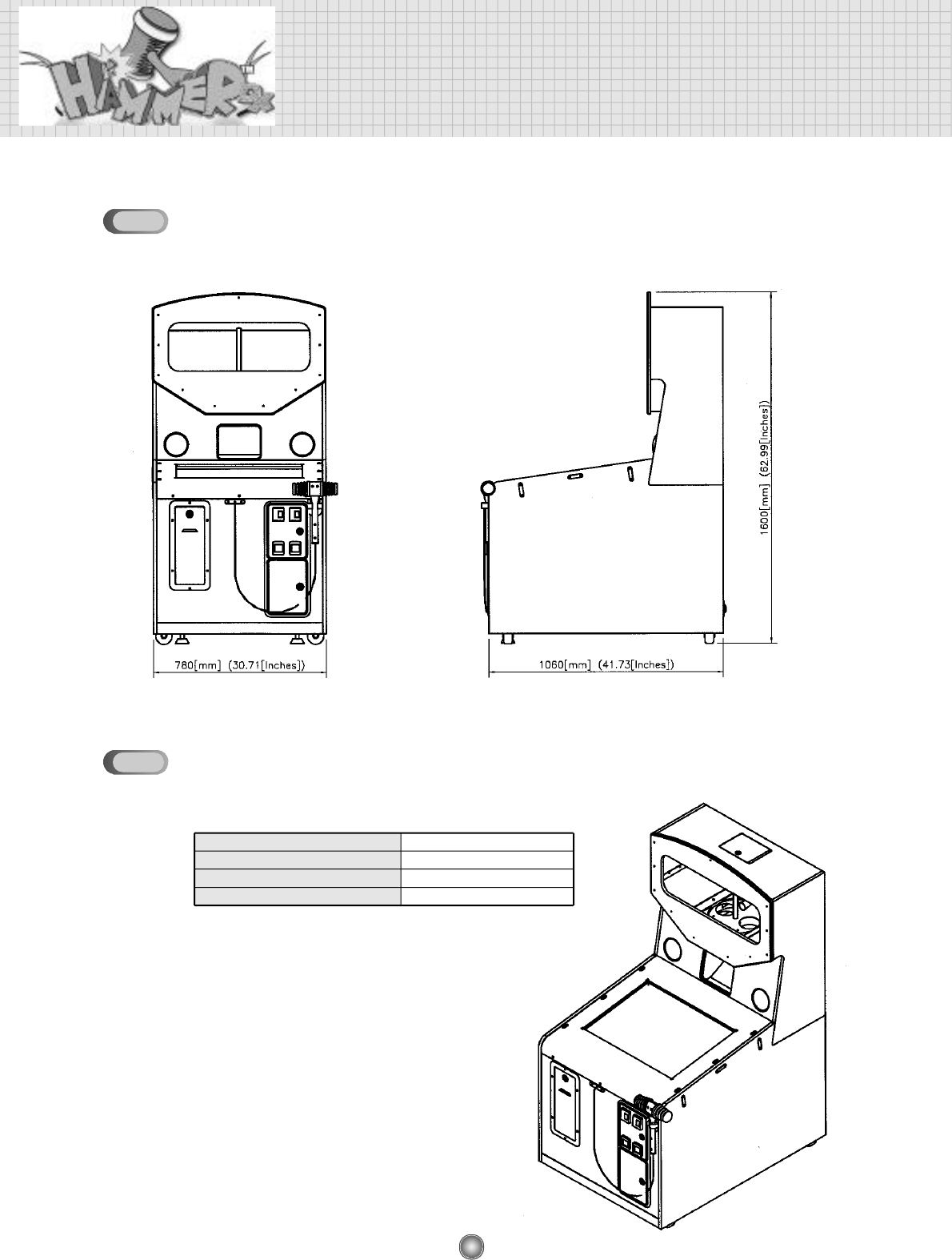
8
1. Specification and Dimensions
DIMENSIONS
POWER CONSUMPTION
DISPLAY
WEIGHT
APPROPRIATE POWER SOURCE
163 (Watts)
29 (Inches)
150 (Kgs)
AC 120 / 220 (V), 50~60(Hz)
SPECIFICATION
1-1
1-2
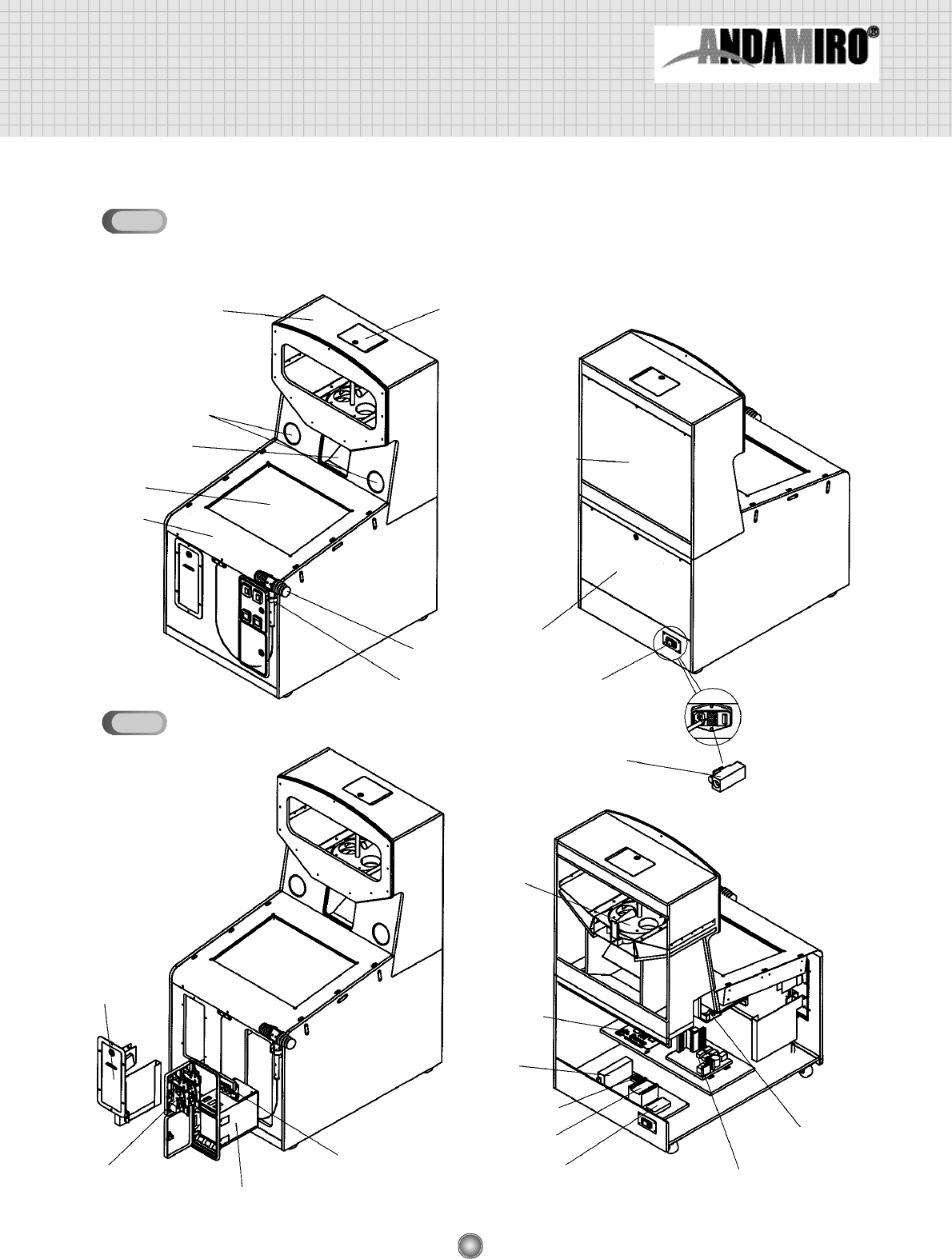
9
2. Name of Parts
EXTERNAL PARTS
UPPER CABINET TOP DOOR
SPEAKER HOLES
PRIZE OUT
LOWER CABINET
HAMMER HANGER
HAMMER REAR LOWER
DOOR
REAR UPPER
DOOR
ROCKER
SWITCH
FUSE
CAPSULE
DISPENSER
MAIN,
I/O PCB
S.M.P.S
TERMINAL BLOCK
TRANSFORMER
NOISER FILTER
MONITOR
CONTROLER
COIN DOOR
(OPTION)
TICKET DOOR
(OPTION)
COIN SELECTOR MONITOR PCB
CRT
CRT
INTERNAL PARTS
2-1
2-2
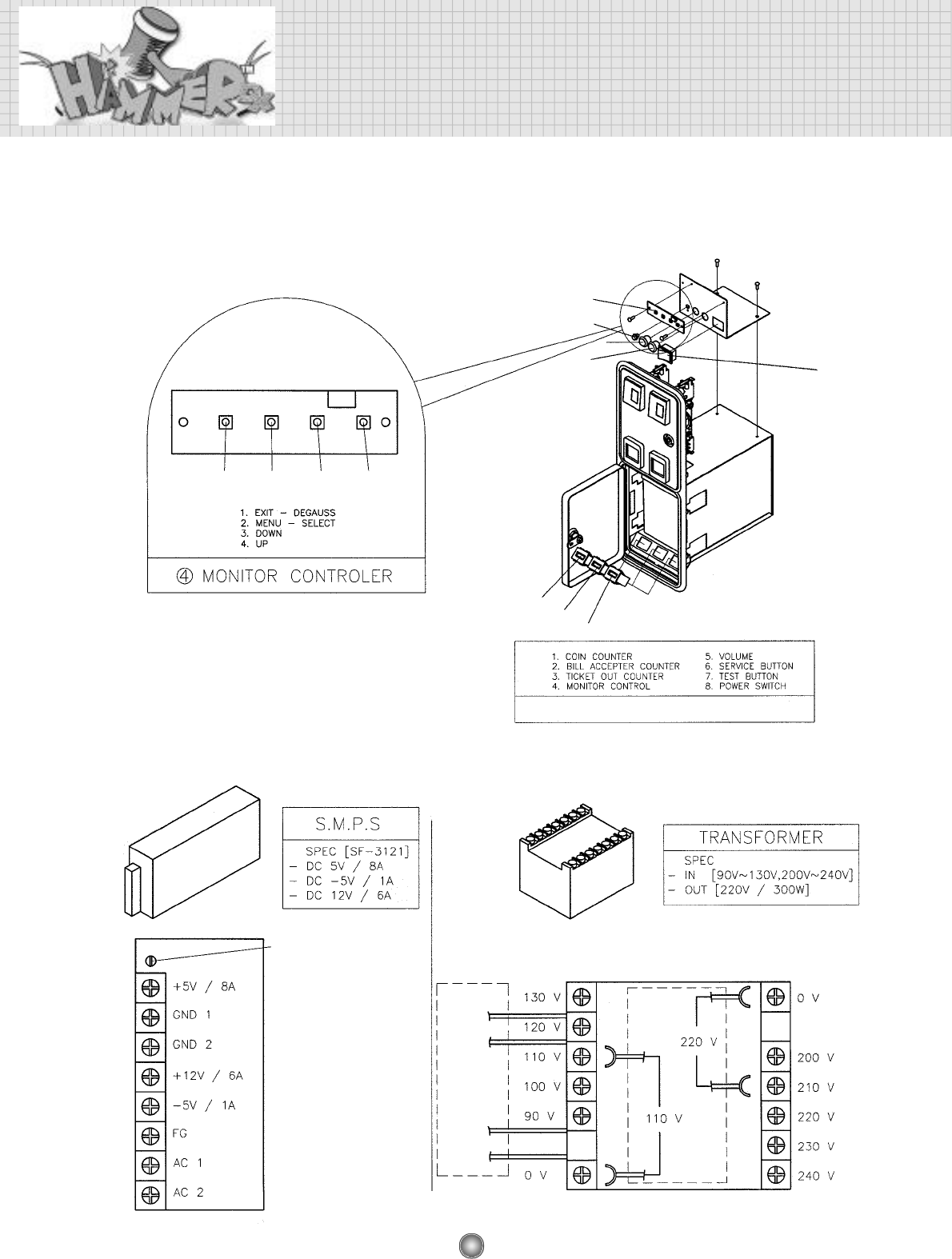
10
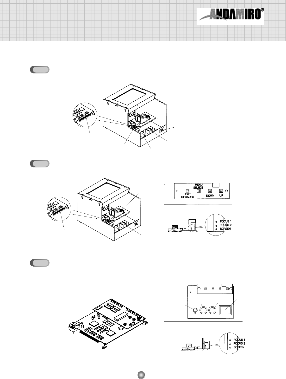
Name of Parts
COIN DOOR AND MONITOR CONTROLER
2-2-1.
S.M.P.S AND TRANSFORMER
2-2-2.
① ② ③ ④
①②③
④
⑤⑥
⑦⑧
※DATA BANK(5-7) SHOWS PRIZE OUT COUNTER
CONNECT THE WIRE ACCORDING TO INPUT VOLTAGE.
VOLTAGE
CONTROL V/R
OUTPUT
INPUT
110V
YELLOW
220V
BLACK
12
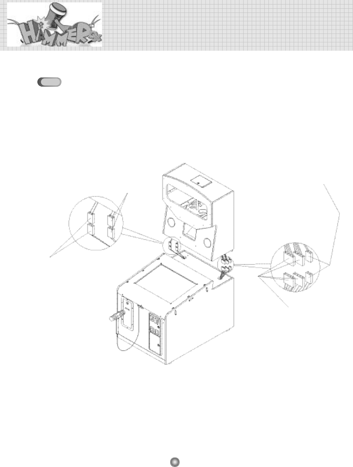
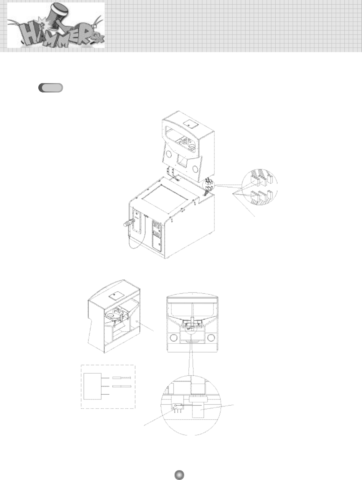
3. How to Assemble
CONNECTOR CONNECTION
SPEAKER CONNECTOR (2p)
CONNECTION SPEAKER CONNECTOR (2p)
CONNECTION
MOTOR & SWITCH CONNECTOR (4p)
CONNECTION - 2EA
CCFL LAMP CONNECTOR(2P)
CONNECTION
3-1
13
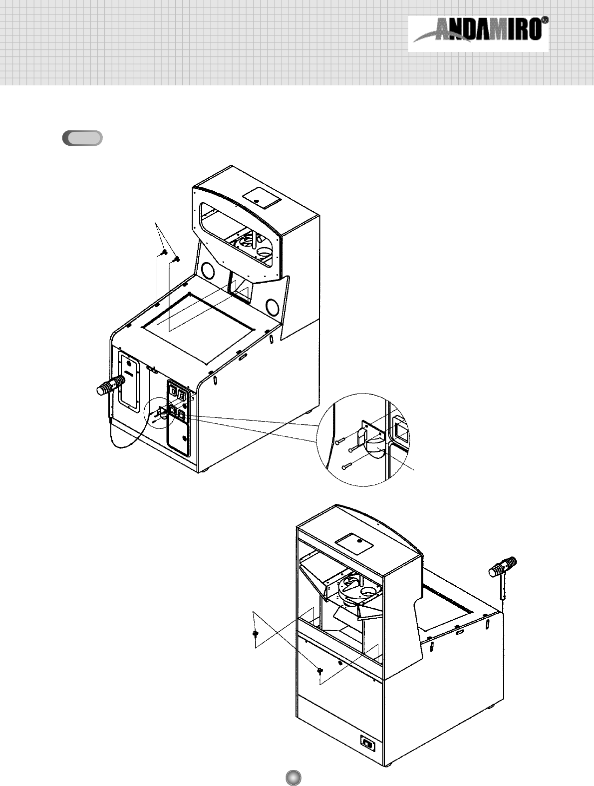
CABINET ASSEMBLY
BLOTS
BLOTS
HAMMER HANGER
CODE NO.: MHATOACRO004
3-2
14
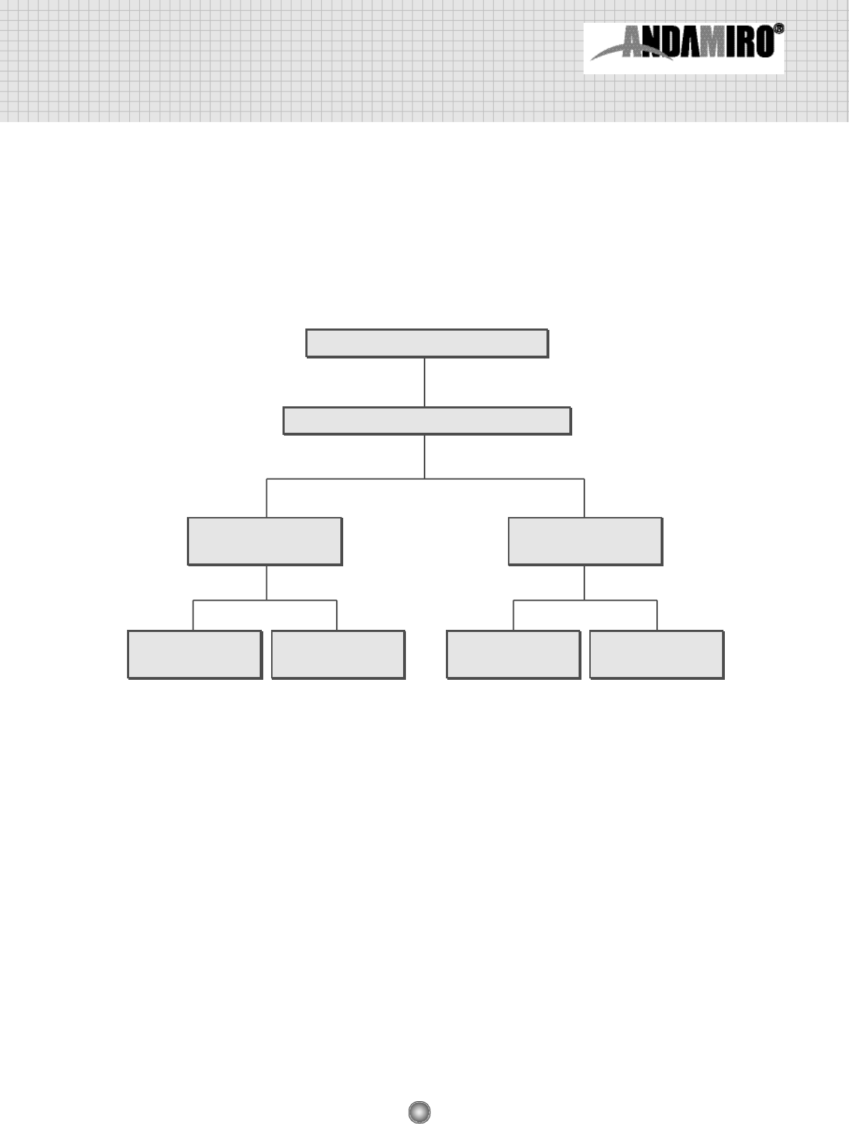
4. Game setup and test mode
When you push the TEST S/W, “SETUP 1” is dispalyed as below. You can setup the game as
you want.
When you push TEST S/W once again, the SETUP 1 disappears and SETUP 2 is displayed.
1
2
PRIZE MODE TICKET MODE
PRIZE MODE TICKET MODE
15
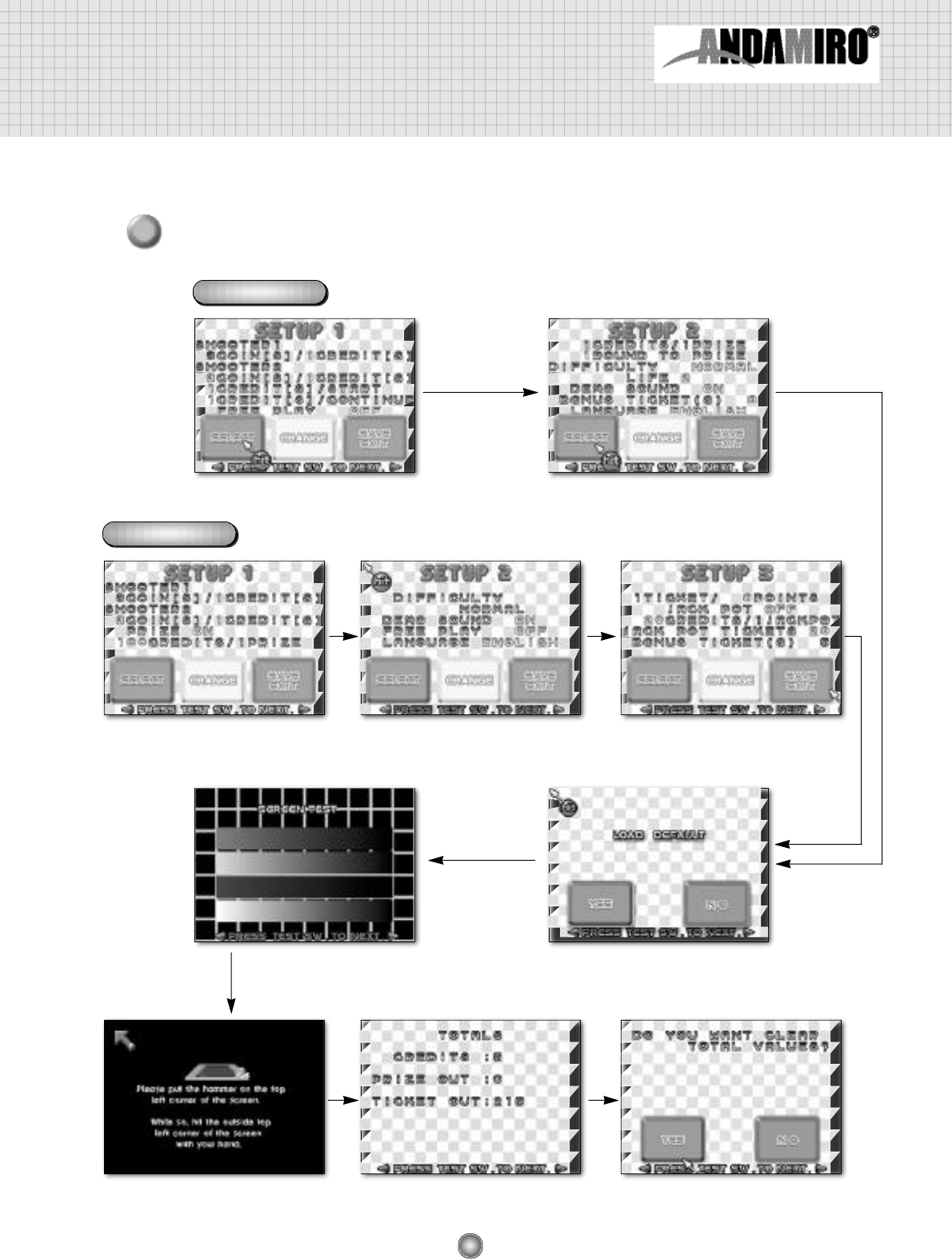
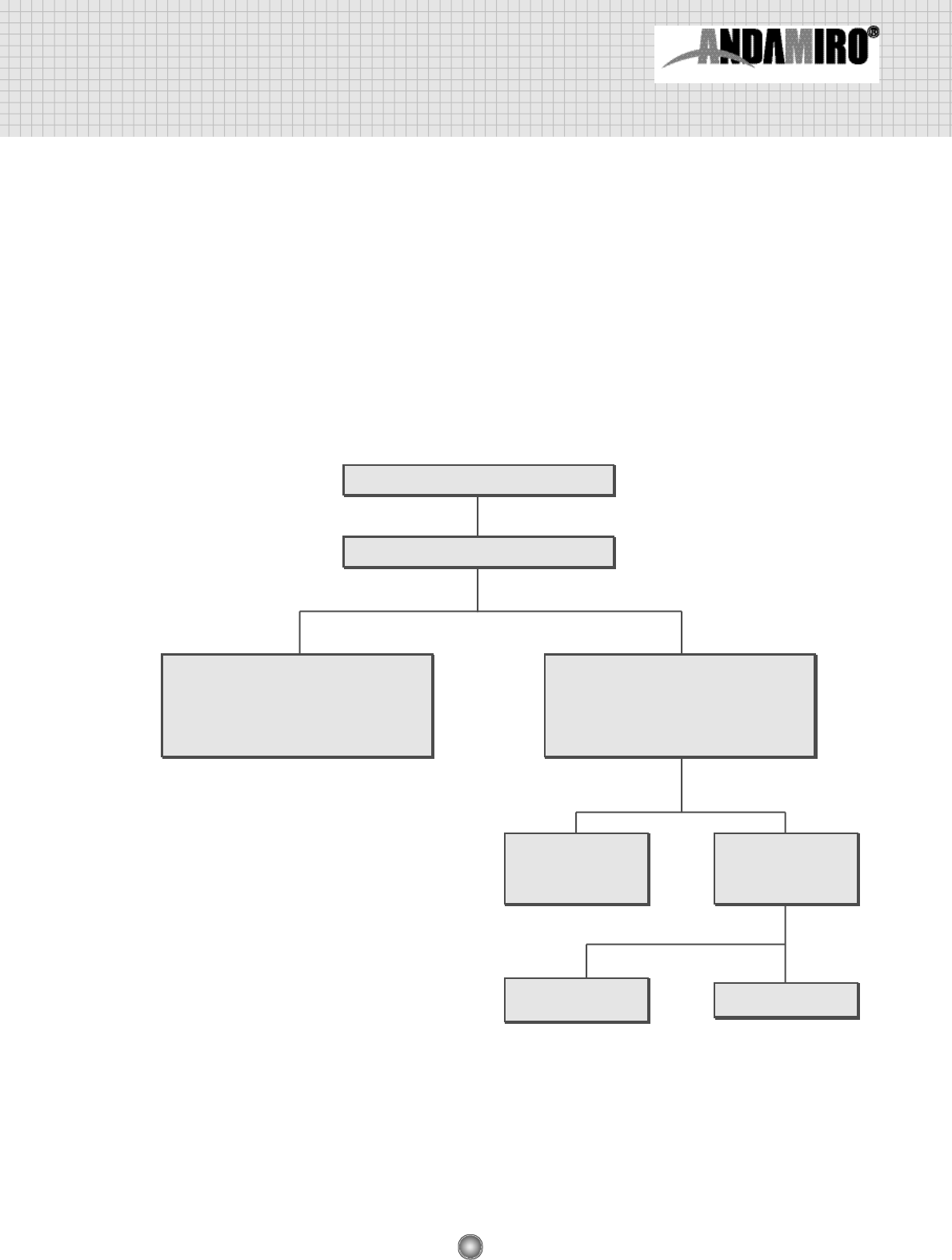
3
Various setup displays appear each time you push the TEST S/W, as shown in the figure below.
PRIZE MODE
TICKET MODE
SETUP 1 SETUP 2
SETUP 1 SETUP 2 SETUP 3
SENSOR SETTING DATA BANK DATA BANK
SCREEN TEST LOAD DEFAULT
16
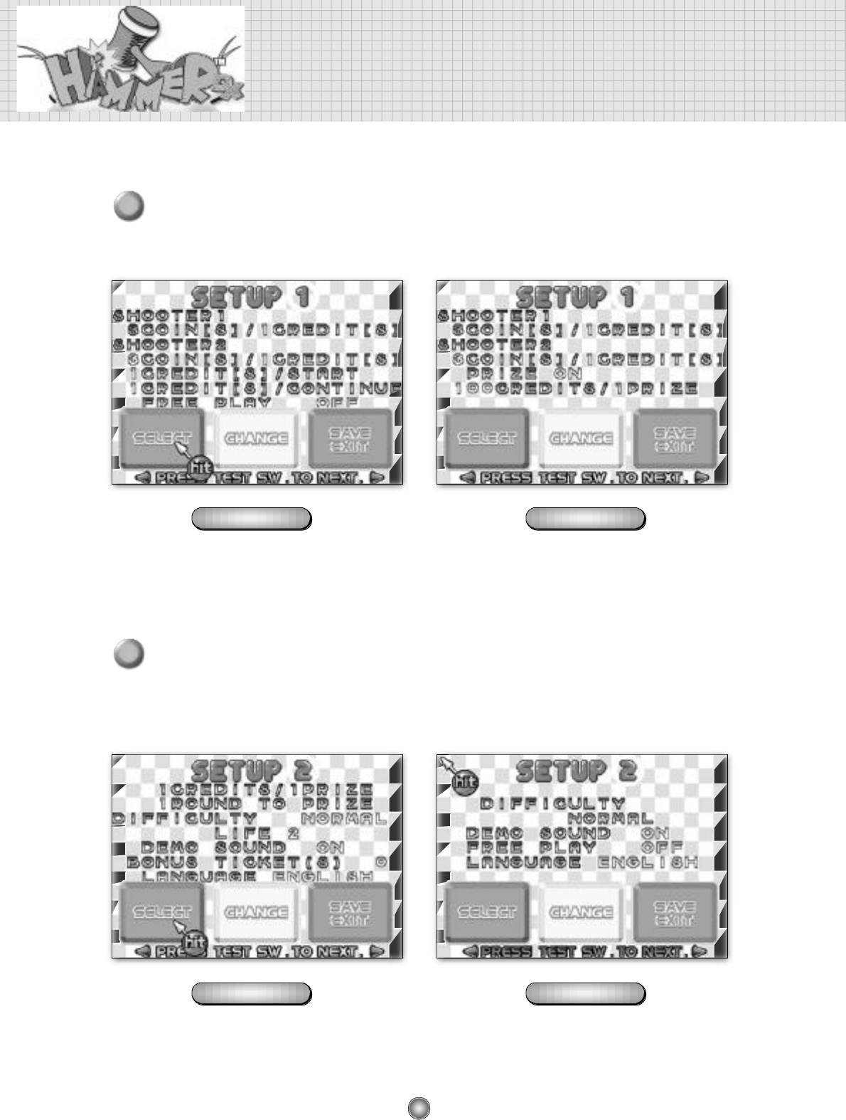
5. Detailed of setup mode
Each designated function in the setup mode can be set by hitting the figure on the screen
with your hammer.
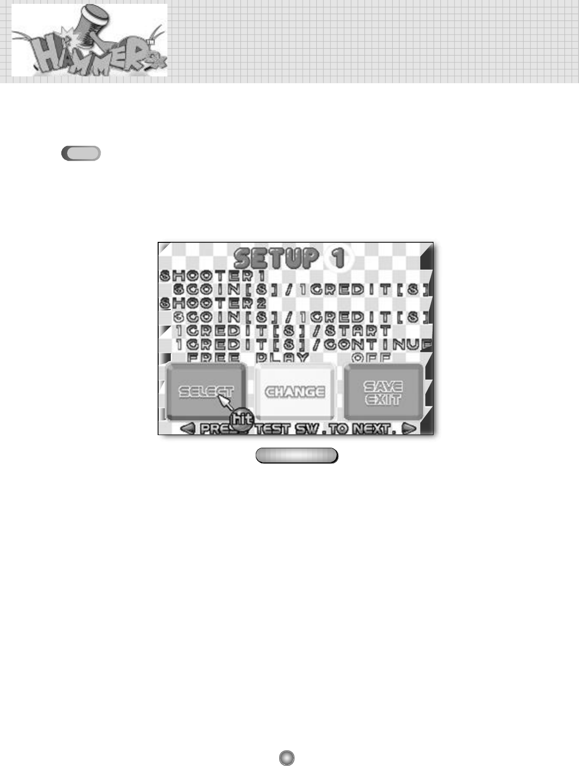
SETUP 1
• The SETUP 1 display allows you to change coin settings.
• You can change the setting values by hitting the “SELECT” button with your hammer as much as you want.
• The location of setup values are changed when you the “CHANGE” button with your hammer.
• Hit the “SAVE EXIT” to save the values you set.
❖SHOOTER1 - COIN(S) / CREDIT(S)
• This is related to the number of coins players insert. You can set how many coins are needed for a
credit (game).
• You can change each of the coin or credit values to equal anywhere from 1~9.
❖SHOOTER 2 - BILL(S) / CREDIT(S)
• This is used when you have a bill-validator installed.
• The details are the same as for those of SHOOTER 1.
❖CREDIT[S] / STA RT
• Set how many credits are required to play the game.
• The setting range is from 1 to 9.
❖CREDIT[S]/CONTUNUE
• Set how many credits are required to continuously play the game.
• The setting range is from 1 to 9.
❖FREE PLAY
•Set up the possibility of free play.
•Setting may be changed to ON/OFF
PRIZE MODE
5-1
17
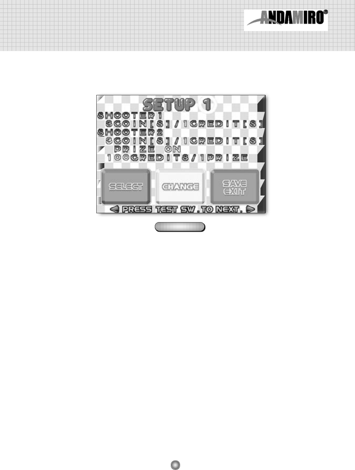
❖SHOOTER 1 - COIN[S]/CREDIT[S]
•This is related to the number of coins players insert. You can set how many coins are needed for a
credit (game).
•You can change each of the coin or credit values to equal anywhere from 1~9.
❖SHOOTER 2 -BILL[S]/CREDIT[S]
•This is used when you have a bill-validator installed.
•The details are the same as for those of SHOOTER 1.
❖PRIZE
•Set whether prize will be provided or not.
•Setting can be changed to ON / OFF.
❖CREDITS/PRIZE
•Players can win the prize according to how many credits are accumulated.
•This is activated when “PRIZE ON” is set.
(Prize never come out if “PRIZE OFF” is set)
•Setting may be changed to 20 / 50 / 100 / 150 / 200
TICKET MODE
18
Detailed of setup mode
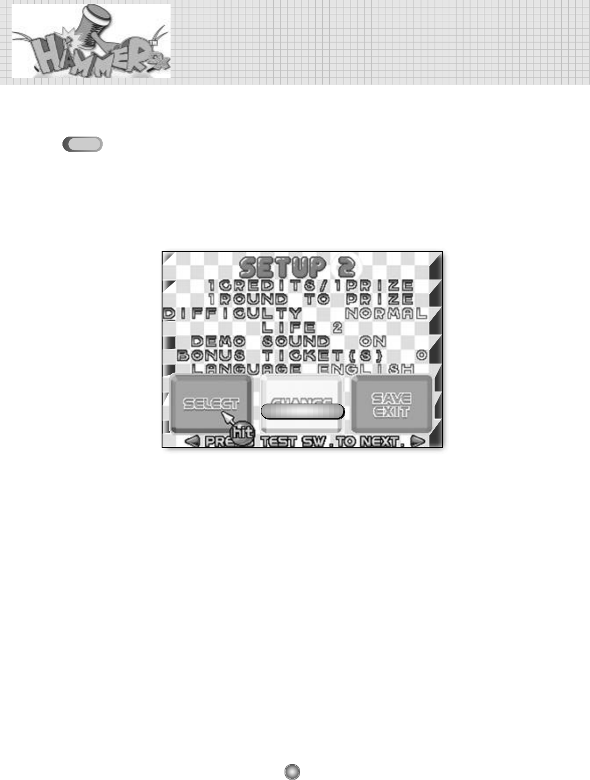
SETUP 2
• The degree of difficulty and language of game are set on the SETUP 2 screen.
• You can change the setting values by hitting the “SELECT” button with your hammer as much as
you want.
• The location of setup values are changed when you the “CHANGE” button with your hammer.
• Hit the “SAVE EXIT” to save the values you set.
❖CREDITS/PRIZE
• Players can win the prize according to how many credits are accumulated.
The higher credits are, the lower the winning percentage is.
• The setting range is from 1 to 400.
❖ROUND TO PRIZE
• Set the number of the play round for getting to the prize out chance.
• The setting range is from 1 to 6.
❖D I F F I C U LT Y
• Set up the degree of diff i c u l t y.
• Setting may be changed to EASY / NORMAL / HARD / VERY HARD
❖L I F E
• Set the number of LIFE a play.
• The setting range is from 1 to 9.
❖DEMO SOUND
• Set up demo sound ouput.
• Setting may be changed to ON / OFF.
PRIZE MODE
5-2
19
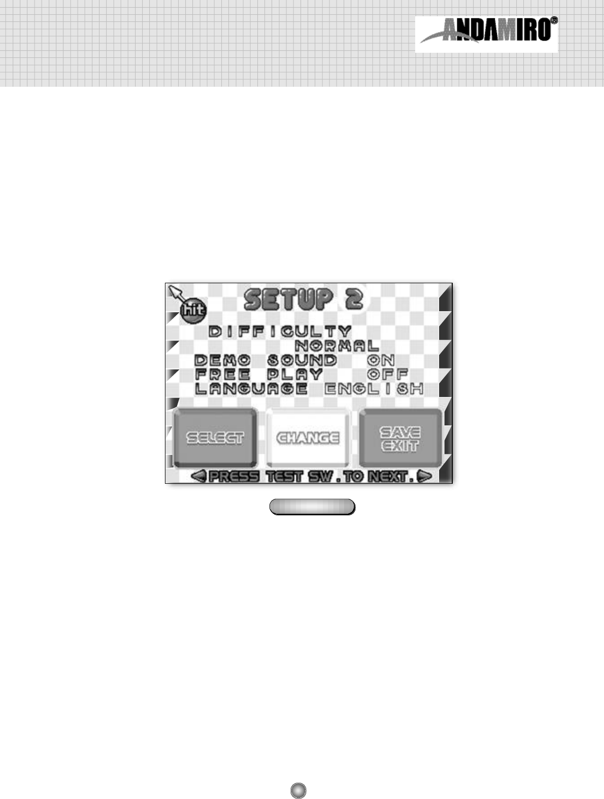
❖BONUS TICKET(S)
• Set the number of ticket(s) regardless of scores.
• The setting range is from 1 to 9.
❖L A N G U A G E
• Set up the language to be used in the menu display, etc.
• Setting may be changed to ENGLISH / KOREAN.
❖D I F F I C U LTY
• Sets up the game’s diff i c u l t y.
• Setting may be changed to EASY / NORMAL / HARD / VERY HARD.
❖DEMO SOUND
• Set up demo sound output.
• Setting may be changed to ON / OFF
❖FREE PLAY
• Set up the possibility of free play
• Setting may be changed to ON / OFF
❖L A N G U A G E
• Set up the language to be used in the menu display, etc.
• Setting may be changed to ENGLISH / KOREAN.
TICKET MODE
20
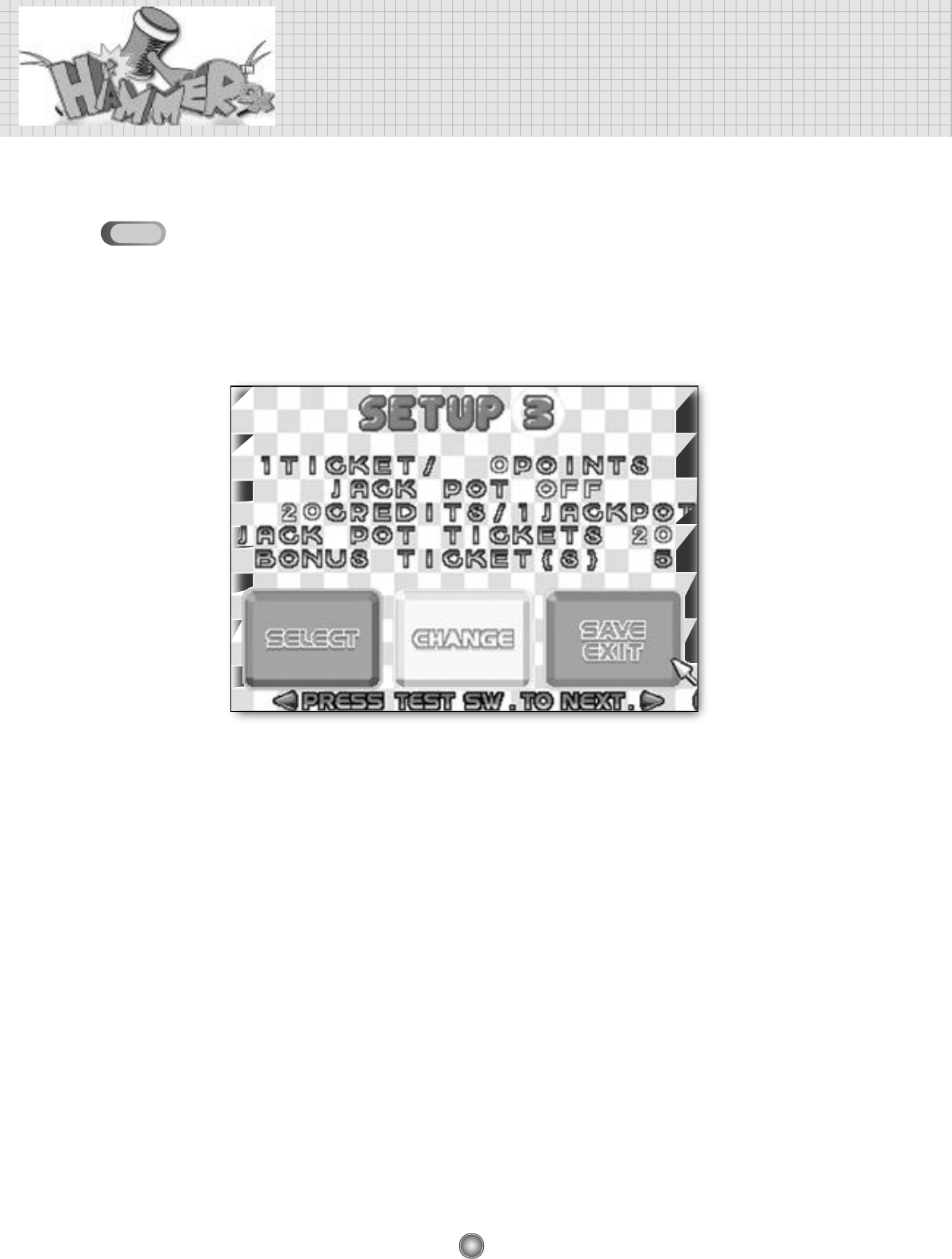
❖T I C K E T / P O I N T S
• Players can win ticket/s according to how many scores players obtain.
• Scores that you can obtain in the play of a game is approximately 1000 points.
(Example : 3 tickets will come out as 1000
÷
300 = 3.33333... If setting 300 points.)
• The scope of setting change ranges from 10 through 600.
❖JACK POT
• Set whether JACK POT exists or not.
• Setting may be changed to ON/OFF.
❖CREDITS/JACK POT
• Set how many of credits are needed to win a JACK POT.
• The scope of setting change ranges from 5 through 200.
❖JACK POT TICKETS
• Set how many ticket will come out in JACK POT.
• The scope of setting ranges is from 5 through 200.
❖BONUS TICKET(S
• Set the number of ticket(s) regardless of scores.
• The setting range is from 1 to 9.
Detailed of setup mode
SETUP 3 (Only for the TICKET MODE)
• Setting may be changed for the ticket on the SETUP 3 screen.
• You can change the setting values by hitting the “SELECT” button with your hammer as much as you want.
• The location of setup values are changed when you the “CHANGE” button with your hammer.
• Hit the “SAVE EXIT” to save the values you set.
5-3
21
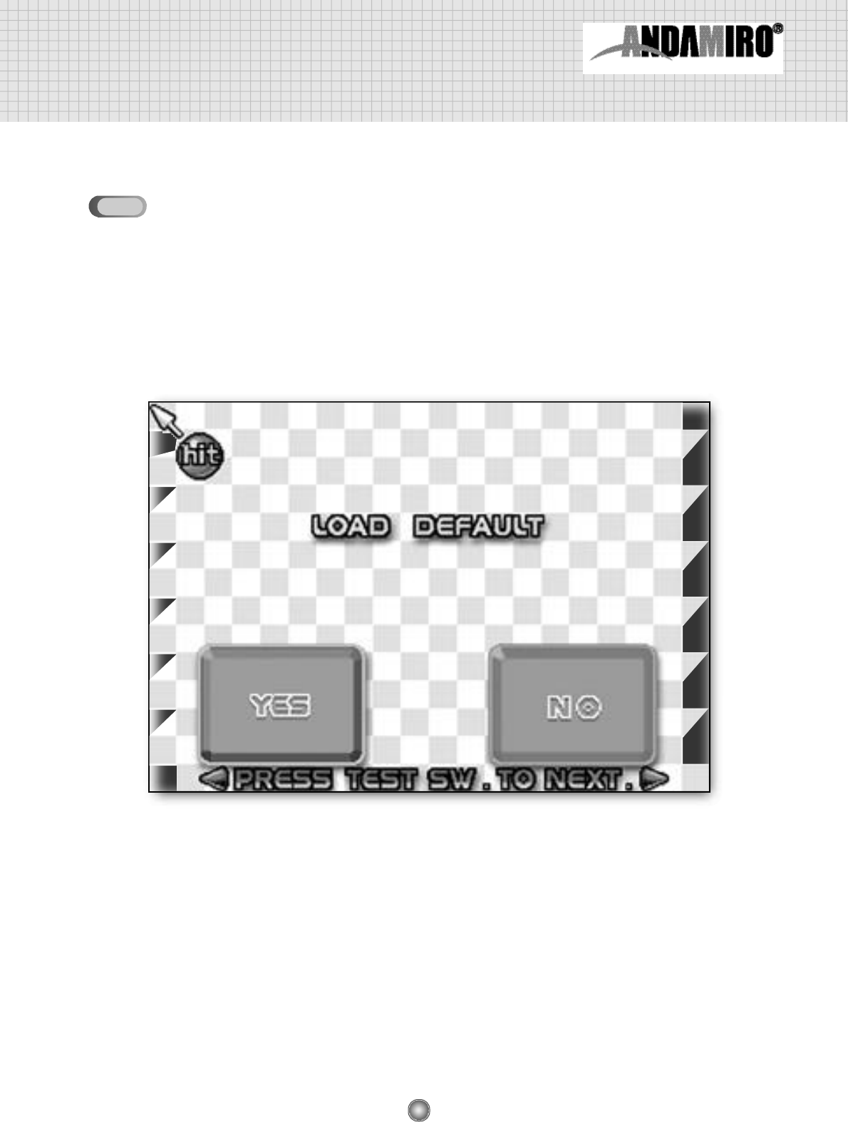
LOAD DEFAULT
• All the manufacturer's default setup values can be saved.
• When you hit the YES button with your hammer, the manufacturer's default values are saved and you
are returned to the game display.
• When you hit the NO button with your hammer, the existing setup values are kept and you are
returnded to the game display.
5-4
22
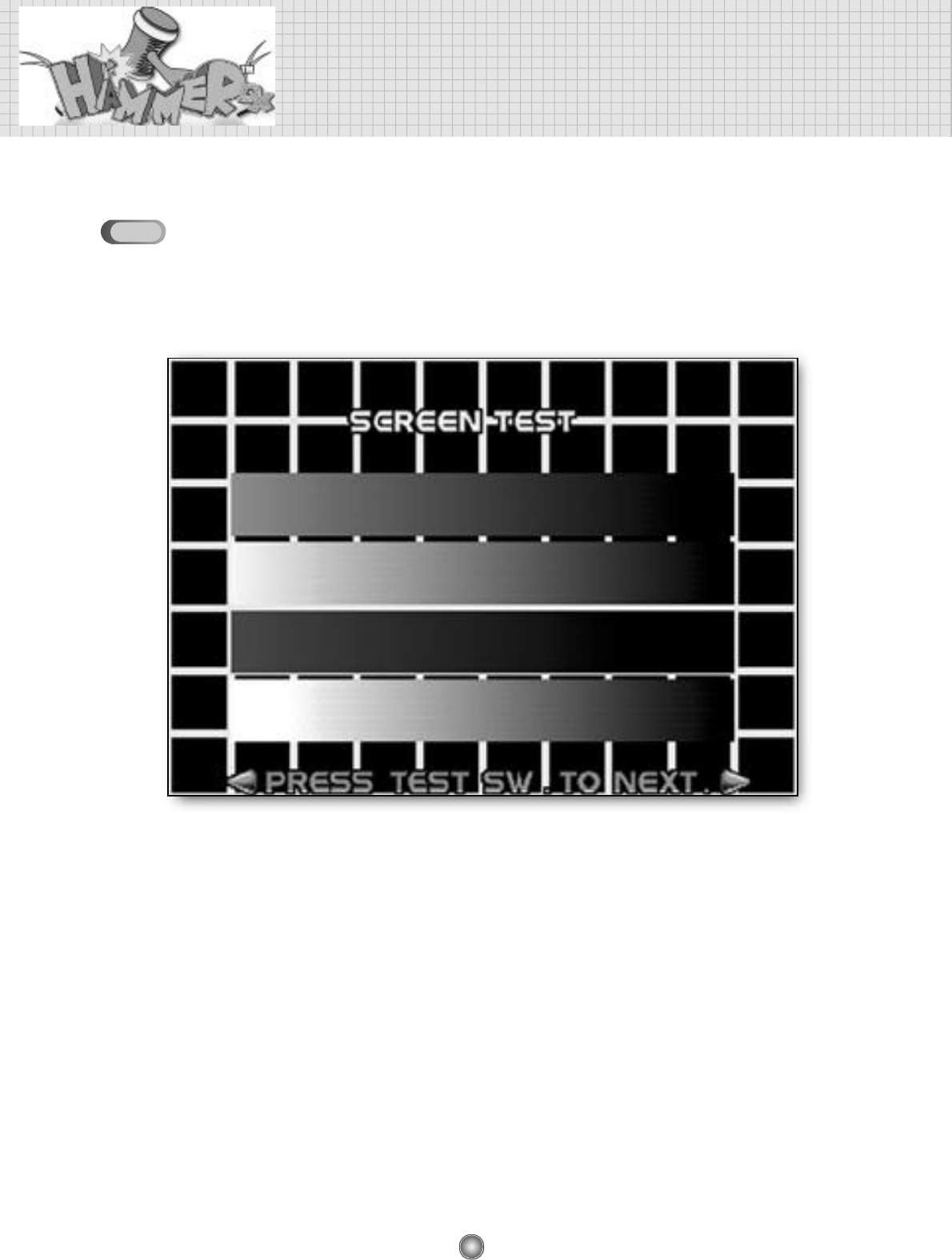
Detailed of setup mode
SCREEN TEST
• This display allows you to test CRT status such as display color, etc.
5-5
23
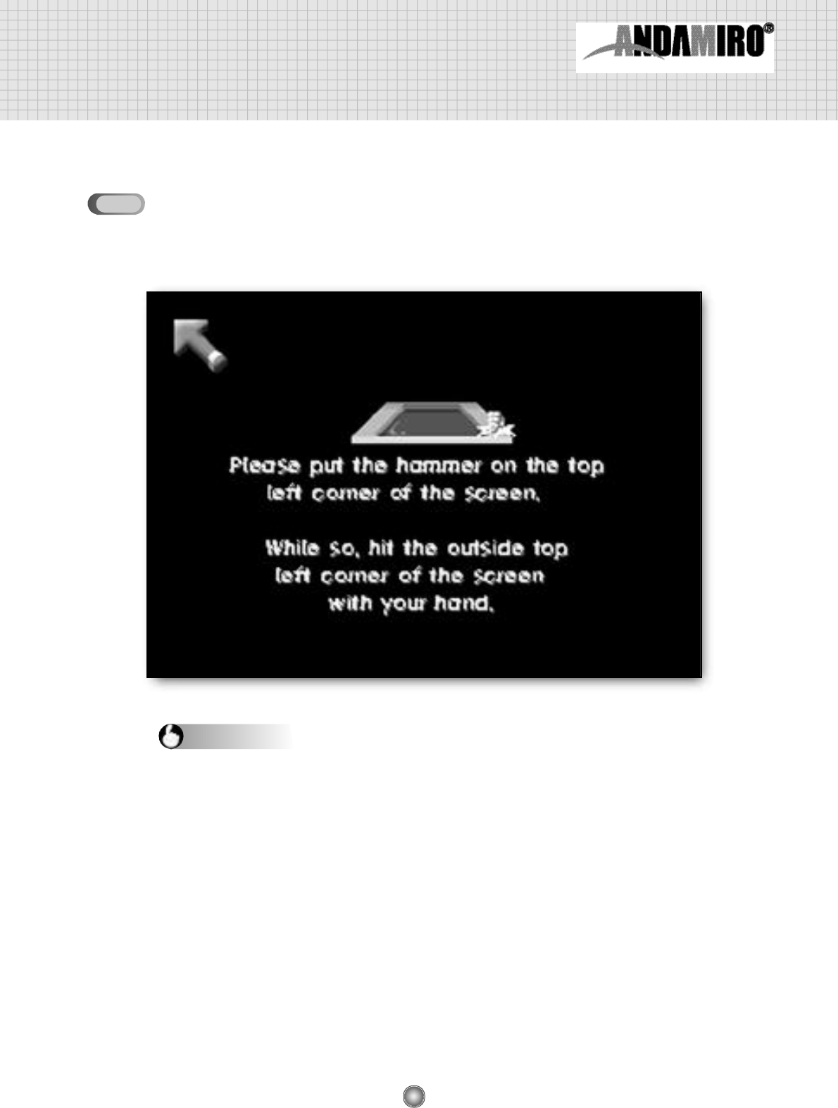
SENSOR SETTING
• Sets up the exact hit-spot where you hit.
• Adjust the exact hit-spot in this display if the actual spot hit and the display spot are diff e r e n t .
1. Collate the hammer to the top-left section of the display, according to the help guides displayed, and then hit
the external steel plate with your fist.
2. A help guide will appear after the arrow moves to the bottom-right of the display.
3. Collate the hammer to the bottom-right section of the display, according to the help guides displayed, and then
hit the external steel plate with your fist.
4. Once the setup is complete, an arrow will appear on the display to follow the hammer's movement.
5. If the arrow does not follow the hammer's movement, the setup was performed improperly. In this case, try to
set up again following the above instructions carefully.
6. If the setup was performed properly, then hit any spot with your hammer.
7. You can move on to the SETUP 1 display.
8. When you hit SAVE EXIT in the SETUP 1 display, all your setup values will be saved and you will be
returned to the game display.
Setup instructions
5-6
24
Detailed of setup mode
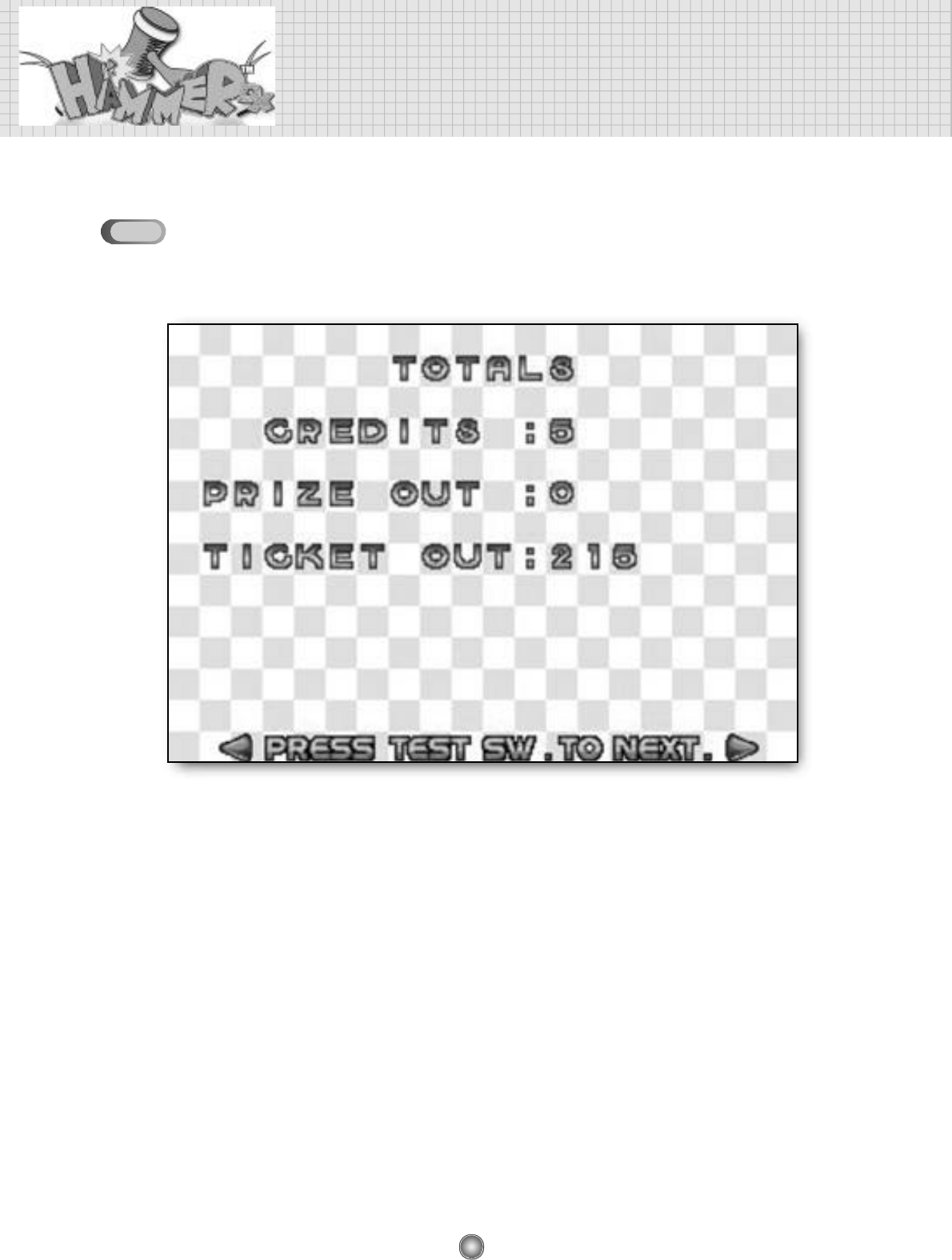
DATA BANK
• This is mode to ensure information for credit, prize and ticket after the game machine is used.
❖C R E D I T S
• CREDITS show how many credits come after the game machine is used.
❖PRIZE OUT
• PRIZE OUT shows how many prizes are provieded after the game machine is used.
❖TICKET OUT
• TICKET OUT shows how many ticket are provided after the game machine is used.
❖All values are 0 in the shipment from factory.
5-7
25
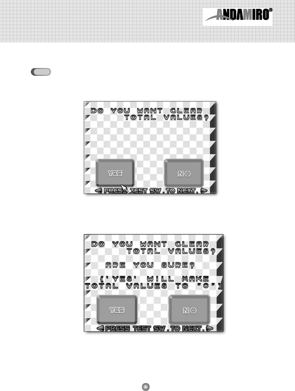
DATA BANK CLEAR
• DATA BANK CLEAR is a mode for deleting the saved values of DATA BANK.
❖YES
• The following screen appears if slaming the YES button with your hammer.
• All contents of the DATA BANK is initialized to 0 if hitting the YES button on the above screen.
❖NO
• Hitting the NO button with a hammer on the above screen allows to move on to the “SETUP 1”
screen without deleting contents of DATA BANK.
5-8
26
6. A/S MODE
You can enter A/S Mode by turning on the power switch with the Test Button pushed.
Before getting to this A/S mode, there shoud be nothing on the screen
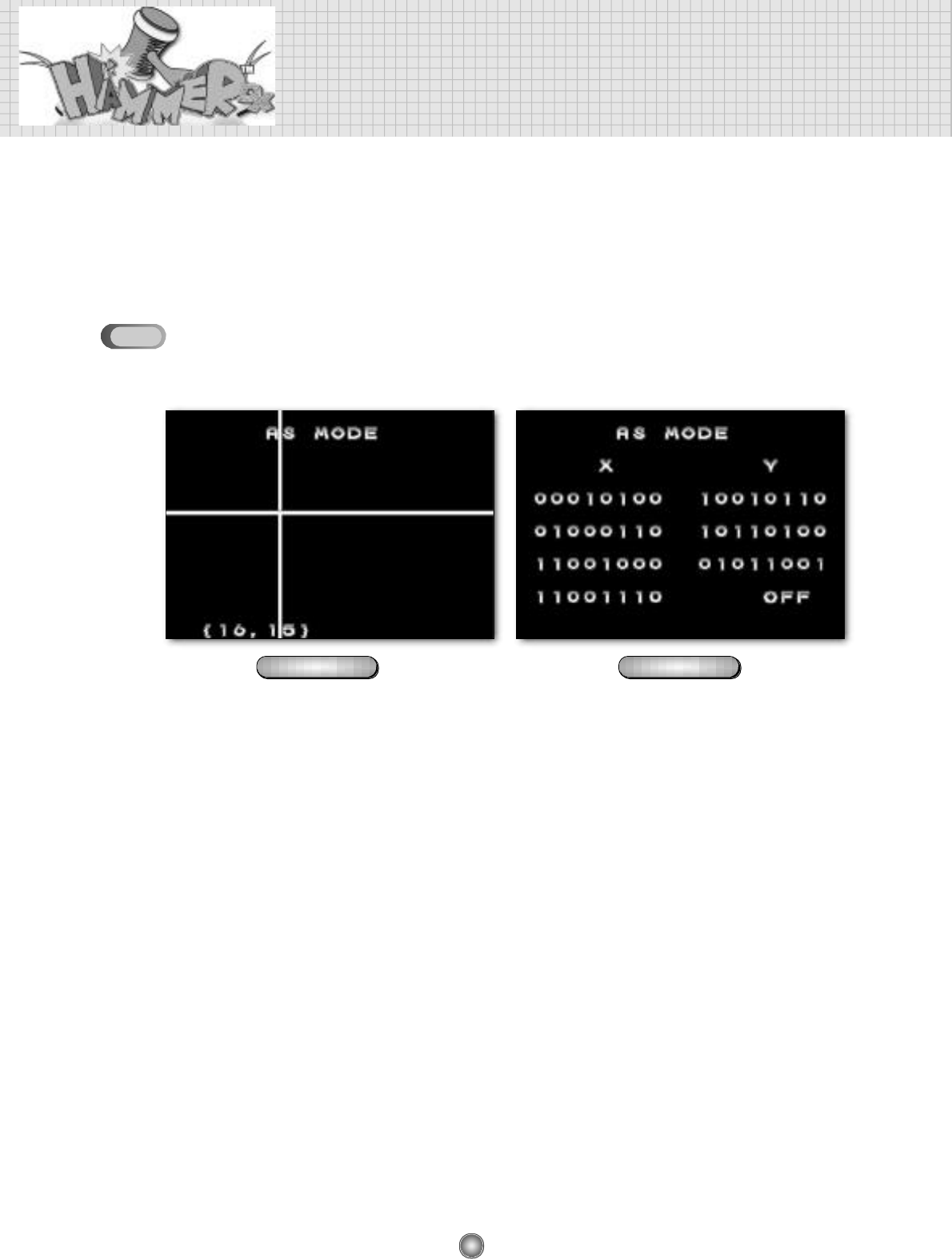
1) When you get to the A/S mode at first, (FF,FF) and no white line should appear.
• Condition: there shoud be nothing on the screen
2) When randon numner and white line are shown like figure 1-1 on the conditioned that
there is nothing on the screen, you have to move to the next AS mode (figure 1-2)
by pushing the test button because the sensors are defective.
• Check point : all the numbers of figure 1-2 should be “O” when all the X,Y sensors are normal.
If there are “1” on the screen,
✽Step #1: try to change “1” to “O” by adjusting the direction of X,Y sensors.
✽Step #2: If you can not chagne“1" to “0”, change the related sensor.
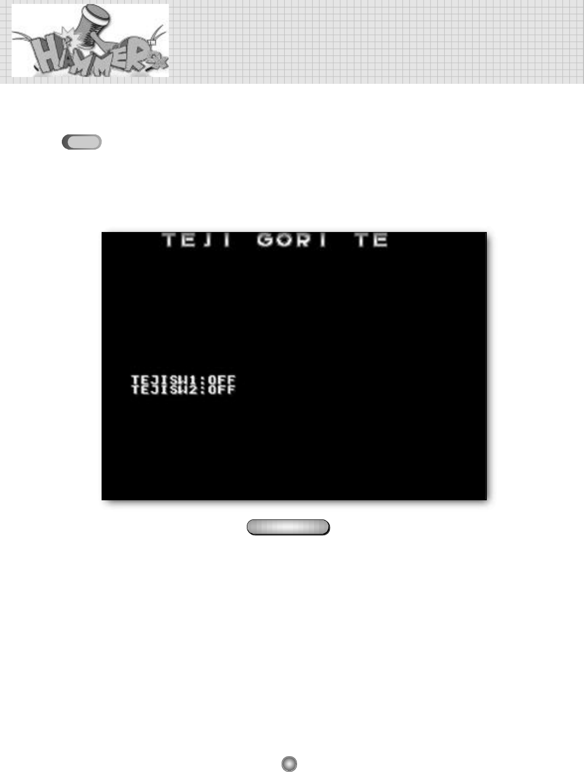
3) Shock sensor test
• To check the shock sensor, hit the screen of the figure 1-2. If “OFF” does not return to “OFF” after
shortly showing “ON”, the shock is deff e c t i v e .
Sensor problem
figure 1-1 figure 1-2
6-16-1

27
4) Although all the numbers are "0" and the shock sensor is in a good condition,
when the sensor does not in the play you have to change the I/O PCB
5) Reference :
• The figures(“0” and “1”) below “X” show whether the sensors set at top and bottom of the monitor
show the number as below:
▶Figure “0” : Nothing is sensed.
▶Figure “1” : Something is sensed or the sensor direction is wrong
• The figures(“0” and “1”) below “Y” show whether the sensors set at left and right of the monitor
show the numbers as below:
▶Figure “0” : Nothing is sensed.
▶Figure “1” : Something is sensed or the sensor direction is wrong
• Figure “0” should be appeared in normal condition.
28
A/S MODE
Mode for checking Capsule Dispenser Ass’y.
• You can move on to the next Mode by pushing the Test Button as shown below.
( Note : in advance check whether DIP swith is on the prize mode before the following steps )
1) Normal condition
• When you hit the screen, the Capsule Dispenser in the Bill Board starts working. Then it stops
working by tuching the Micro Switch to the Capsule Dispenser.
figure 2-1
6-2
29
Hit the screen of figure 2-1
Check the motor of the Capsule Dispenser
Check the input
VDC to the motor
repalce the mirco
switch or the motor repalce I/O board repalce the mirco
switch repalce I/O board
Check the
mirco switch
2) When the Capsule Dispenser ass’y does not work,
Hit the screen of figure 2-1
Check the motor of the Capsule Dispenser
Check the input
VDC to the motor
repalce the mirco
switch or the motor repalce I/O board repalce the mirco
switch repalce I/O board
Check the
mirco switch
NO
12V not 12V NO OK
OK
30
A/S MODE
Mode for checking the Ticket Dispenser
You can move on to the next Mode by pushing the Test Button as shown below.
1) Normal condition
• When you hit the screen of the figure3-1, the Ticket dispenser starts to work until the ticket comes
o u t .
figure 3-1
6-3
31
Hit the screen of figure 3-1
Check the input
VDC to the ticket
dispensor
repalce I/O board
replace the ticket
dispenser
replace I/O board
2) When the ticket does not work in the game play,
( Note : in advance check whether DIP swith is on the ticket mode before the following steps )
Step#1 : push the button of the ticket dispensor and find if the ticket does not come out, replace the
d i s p e n s o r. Otherwise take the step#2
Step#2 : check the connectors between the ticket dispenser and I/O board If all the connectors are
well connected, move to the step#3.
Step#3 :
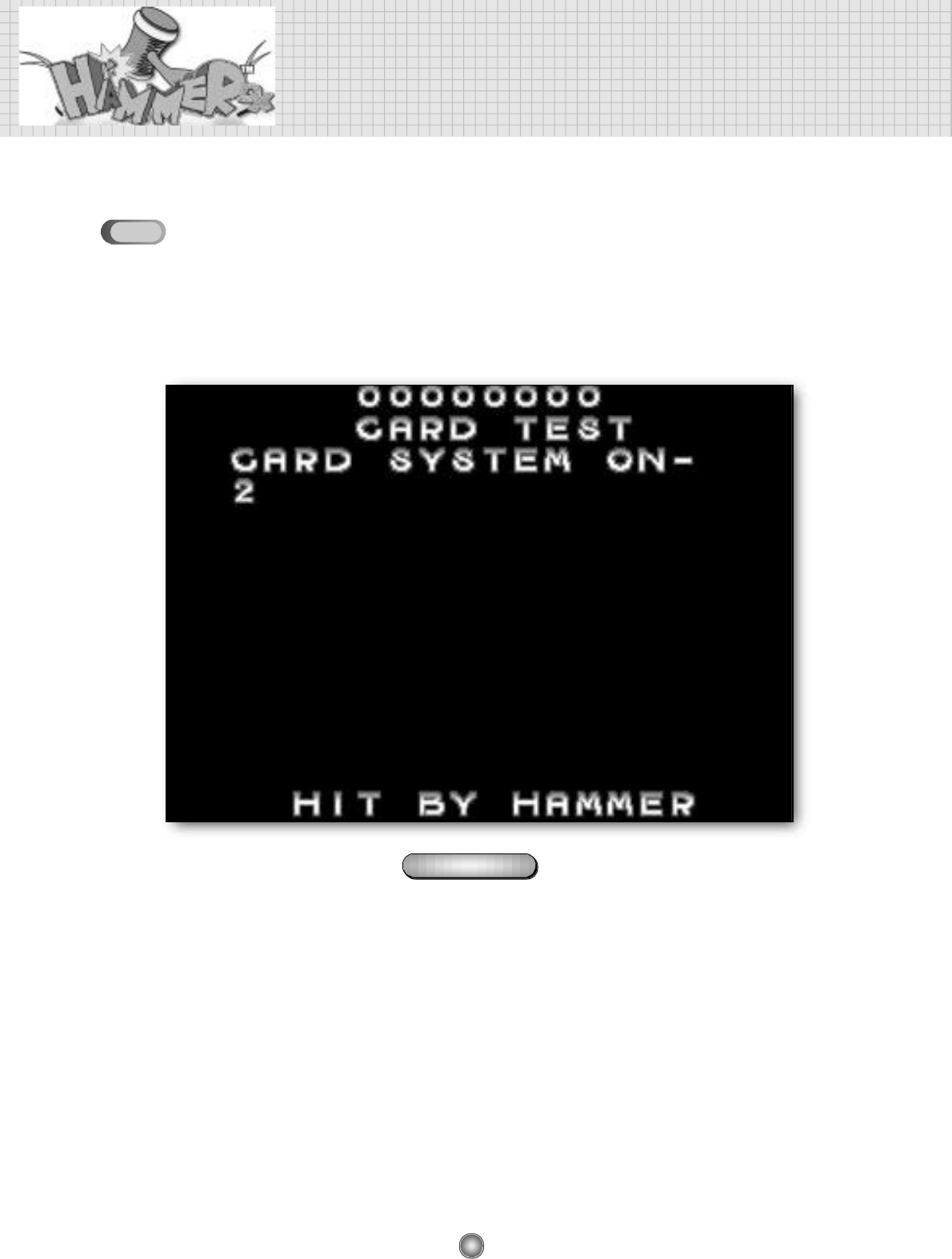
※Except for the error of sound and graphic, I/O borad should be generally checked at first when no
ticket-out and no prize-out happen.
Go to the card test (figure3-1)
Hit the screen of figure 3-1
In this situation, if the ticket does not
come out in the game play replace the
I/O PCB
again push the button of the ticket
dispenser and find whether the
tickets come out
Check the input
VDC to the ticket
dispensor
repalce I/O board
replace the ticket
dispenser
replace I/O board
When a ticket
comoes out When a ticket does
not come out
OK NO
12V not 12V
32
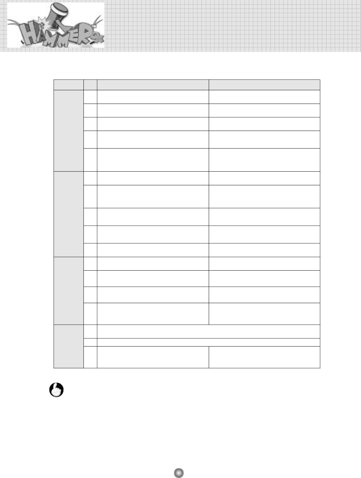
7. TROUBLE SHOOTING
P r o b l e m
p r i o r i t y
STEP 1 STEP 1
No sound &
no picture
No picture
No sound
COIN MECH
P R O B L E M
1
Check the voltage status of input VAC If it is no voltage, check the fuse and the disconnection of AC
c o r d
2
3
4
Check AC lamp in the billboard cabinet If it is O.K., the input VAC and the power until the transformer
is in a good condition.
Mesure the input VAC of the transformer If the input VAC is 110V or below 120V, change the 120V
line of the input VAC to 110V line
Check whether the LED of the SMPS is flickering at blue color
and measure the input VAC of power SMPS
If the output VDC of the power SMPS are over or below 12V
and 5V, adjust them with the voltage controller of SMPS.
5
Check the input VDC of the main PCB and check out the input
VDC after separating JAMMA connector from the main PCB
a) If the input VDC does not keep the regular voltages (12V and 5V)
and b) if the input VDC keeps the regular value after disconnecting
JAMMA, replace the main PCB.
1
Measure the input VAC voltage of the transformer
If the input VAC is 110V or below 120V, change the 120V line of
the input VAC to 110V line
2
Check the sound of the high voltage part of the monitor board
when the machine is ON.
In case of no sound, the monitor board is defective. Try turn on the
machine 20 minites after power off because the protector circuit is
under working. If still no sound, replace the monitor board
3
Slightly turn right the screen volume in the high voltage part of
the monitor board and see if there is white lines on the screen.
If there is white lines, the main PCB is deffective. If not, the monitor
board is deffective.
4
Check whether the LED of the SMPS is flickering at blue color
and measure the input VAC of power SMPS
If the output VDC of the power SMPS are over or below 12V and
5V respectively, adjust them with the voltage controller of SMPS.
5
In case of the picture noise, repalce the main PCB.
After replacing the main PCB, there is still the picture noise, check
again the output VDC.
1
Mesure the input VAC of the transformer
If the input VAC is 110V or below 120V, change the 120V line of
the input VAC to 110V line
2
Check whether the LED of the SMPS is flickering at blue color and
measure the input VAC of power SMPS
If the output VDC of the power SMPS are over or below 12V and
5V respectively, adjust them with the voltage controller of SMPS.
3
Check the sound wire, and maximize the volume of the main PCB
and check the sound in adjusting the volume by the front volume
c o n t r o l l e r
If the noise happens in adjusting the volume by the front volume
controller, replace the main PCB.
4
check the input VDC of the main PCB and check out the input
VDC after separating JAMMA connector from the main PCB
1
In case of the mechanic COIN mech, check the MICRO SWITCH. In case of the electronic coin mech check the VDC(YELLOW
LINE=VDC 12V, BLACK LINE=GND, WHITE=SIGNAL).
2
As a next step, check all the connectors.
3
check the input VDC of the main PCB and check out the input
VDC after separating JAMMA connector from the main PCB
a) If the input VDC does not keep the regular voltages(12V and
5V) AND b) if the input VDC keeps the regular value after
disconnecting JAMMA, replace the main PCB.
a) If the input VDC does not keep the regular voltages (12V and 5V)
AND b) if the input VDC keeps the regular value after disconnecting
JAMMA, replace the main PCB.
1) VDC : DC Voltage on SMPS
2) VAC: AC Voltage
3) Voltage setting status at the factory
The input VAC to the transformer is 120V which is USA regular voltage. the outpout VAC from the
transformer is 220V
If the AC voltage in the location is around 110V, the output VAC from the transformer is below
220V. To make 220V, change the 120V line of the input VAC to the 110V line. If the AC voltage in
the location is around 90V, change the 120V line of the input VAC to the 90V line
n o t e
33
CHECK POINTS IN CASE OF NO VIDEO AND NO SOUND
CHECK POINTS IN CASE OF NO VIDEO
JAMMA
MAIN, I/O PCB
M A I N M O T O R
PCB
MONITOR CONTROL
MONITOR PCB
TRANSFORMER
JAMMA
S.M.P.S
TRANSFORMER
ROCKER SWITCH
7-1
7-2
CHECK POINTS IN CASE OF NO SOUND
7-3
MAIN, I/O PCB
SOUND VOLUME
MONITOR PCB
MAIN CONTROL
AC POWER S/W
SERVICE
BUTTON
FRONT
SOUND
VOLUME
TEST
BUTTON
34
TROUBLE SHOOTING
PROBLEMS OF CAPSULE SUPPLYER
CONFIRM THE STATUS OF
MOTOR & SWITCH CONNECTOR
CONFIRM THE STATUS OF
MOTOR & MOTOR WIRE
CONNECTION
CONFIRM THE STATUS OF
SWITCH & SWITCH WIRE
CONNECTION
N.O
G
N.C
MICRO SWITCH
7-4
35
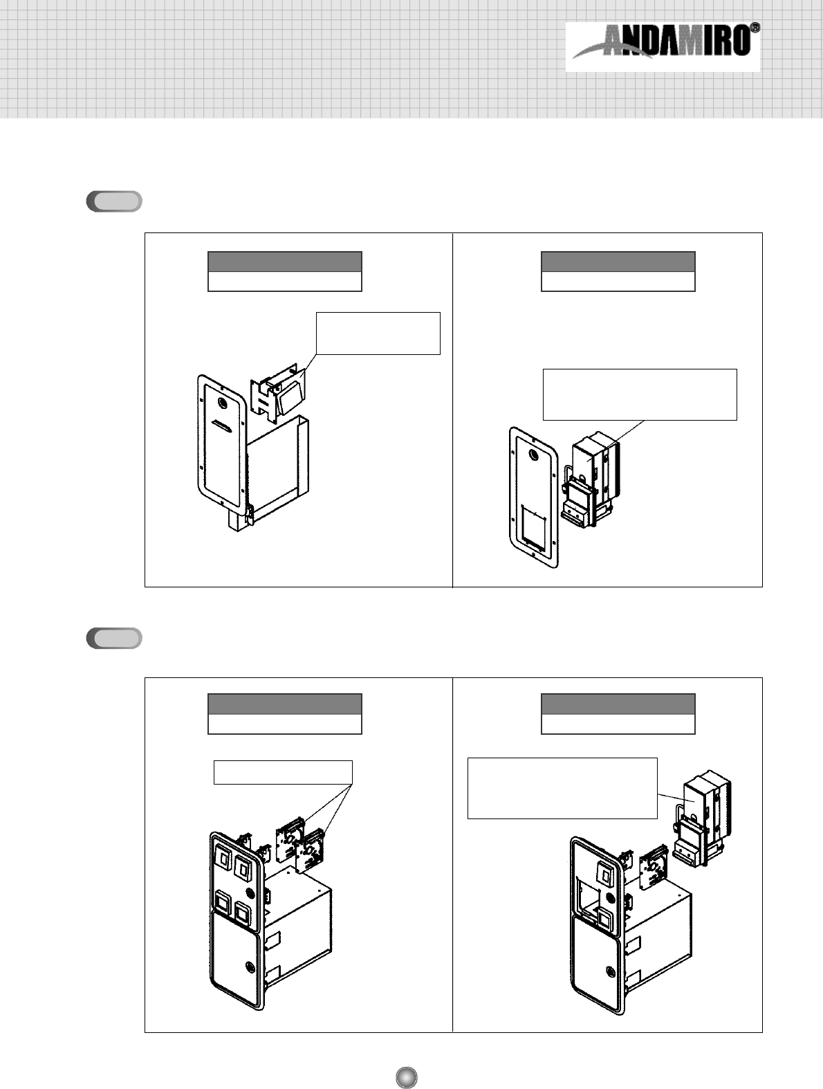
8. OPTION
OPTION 1
TICKET DOOR OPTION
COIN DOOR OPTION
DELTRONIC LABS
TICKET DISPENSER
•MARS BILLACCEPTOR
•AE2400 SERIES UPSTACKER
•115 VAC MODEL
COIN SELECTOR •MARS BILLACCEPTOR
•AE2400 SERIES UPSTACKER
•115 VAC MODEL
TICKET DISPENSER INSTALLED
OPTION 2
BILL ACCEPTOR INSTALLED
OPTION 1
2 COIN INSTALLED
OPTION 2
1 COIN / 1 BILL ACCPTOR INSTALLED
8-1
8-2
36
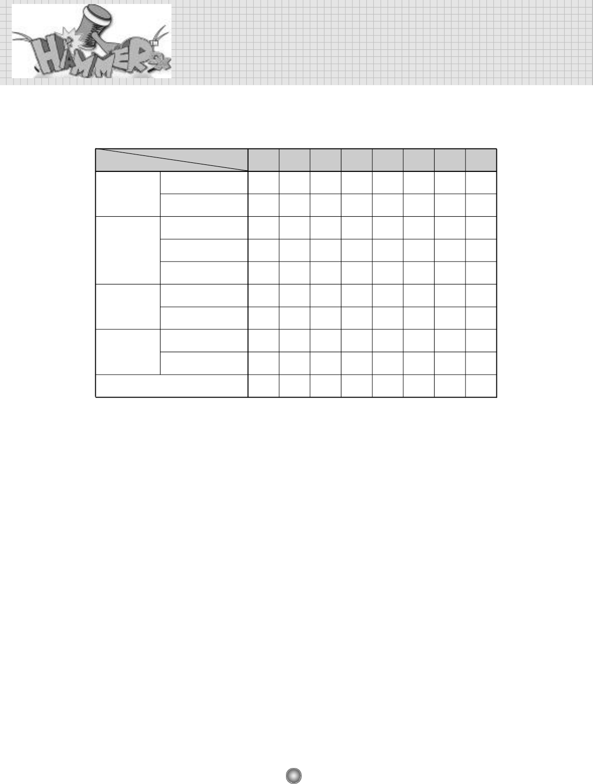
9. DIP S/W Description
D I P 1 D I P 2 D I P 3 D I P 4 D I P 5 D I P 6 D I P 7 D I P 8
O F F
O N
O F F
O N
O F F
O F F
O F F
O N
O N
O F F
O F F O F F O F F
O N
O F F
IN USE
NOT IN USE
PRIZE MODE
TICKET MODE
GAME MODE
IN USE
NOT IN USE
D E B U G
M O D E
M O D E
PAUSE
M O D E
IN USE
NOT IN USE
WA R N I N G
SOUND
DIP S/W NOT IN USE
D I P
C O N T E N T S
❖To put the mode into the prize vending machine, you set up “1CREDITS/1PRIZE” in the setting
mode of SETUP 2. Whenever the play the prize is given freely.
❖In case of the ticket dispenser, you can five away the ticket(s) free of charge in the SETUP 3(ONLY
FOR THE TICKET MODE) as t he following :
1 TICKET / 0 POINTS … 1 ticket free
2 TICKET / 0 POINTS … 2 ticket free
3 TICKET / 0 POINTS … 3 ticket free
37
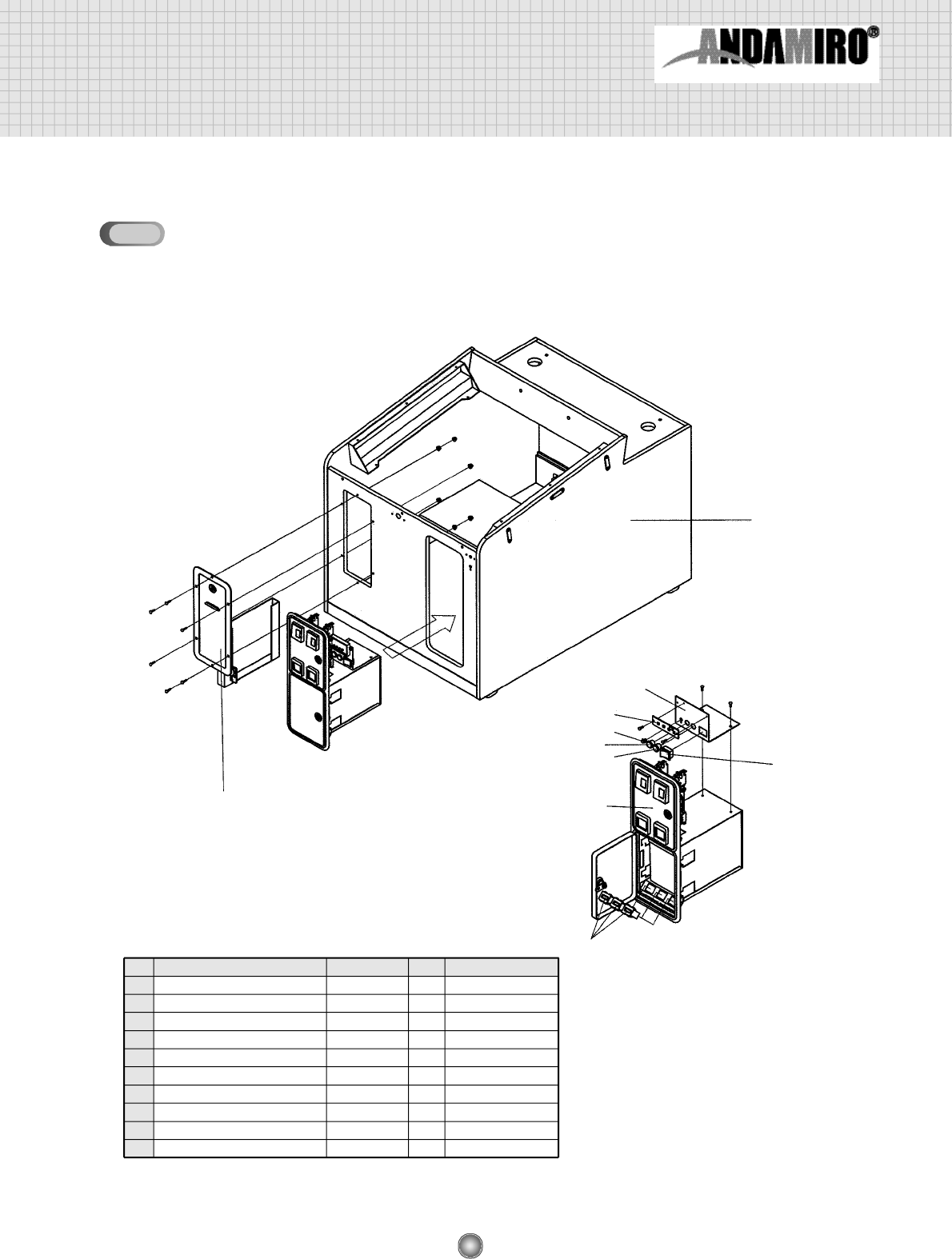
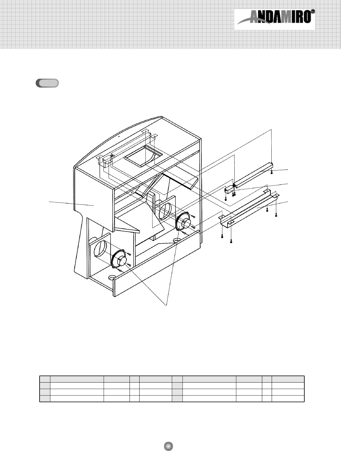
10. ASSEMBLY DRAWING AND PARTS LIST
ASSEMBLING CABINET LOW(1)
①
②③
⑩
④
⑤
⑥
⑦
⑧⑨
NO
①
②
③
④
⑤
⑥
⑦
⑧
⑨
⑩
NAME SPEC QTY CODE NO.
CABINET LOW
TICKET DISPENSER DOOR
COIN DOOR ASS’Y
TEST BUTTON BRACKET
MAIN CONTROL BOARD
VOLUME
PUSH BUTTON SWITCH
PUSH BUTTON SWITCH
ROCKER SWITCH
COUNTER
AMTD100A
AMCD-200B
BA25Y-500Ω
412W
412R
T-120 4P
AMMC-612
1
1
1
1
1
1
1
1
1
3
MHAT0WOO002
AHAM0PRE001
AZZZ0COD001
MHAM1MEP015
MELE0VOL003
MELE0PUS002
MELE0PUS001
MELE0SWI004
MZZZ0COU001
10-1
38
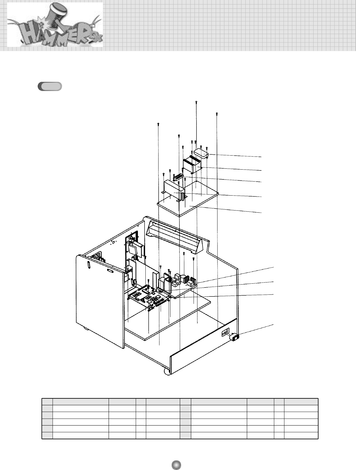
ASSEMBLY DRAWING AND PARTS LIST
ASSEMBLING CABINET LOW(2)
②
①
⑤
⑥
⑧
⑦
⑨
③
④
NO
①
②
③
④
⑤
NAME SPEC
QTY
CODE NO.
MONITOR BOARD
MAIN
I/O PCB ASS’Y
ROCKER SWITCH
NOISE FILTER
0717-1S
250V-10A
1
1
1
1
1
MHAM0PCB001
AHAM0PCB006
AHAM0PCB007
MELE0SWI001
MELE0NOI001
NO
⑥
⑦
⑧
⑨
⑩
NAME SPEC
QTY
CODE NO.
TRANSFORMER
POWER-SMPS
TERMINAL BLOCK
MDF TRANSFORMER
SF3121
6P
1
1
1
1
MELE0TRF016
MELE0SMP015
MELE0TEB001
MHAM0WO006
10-2
39
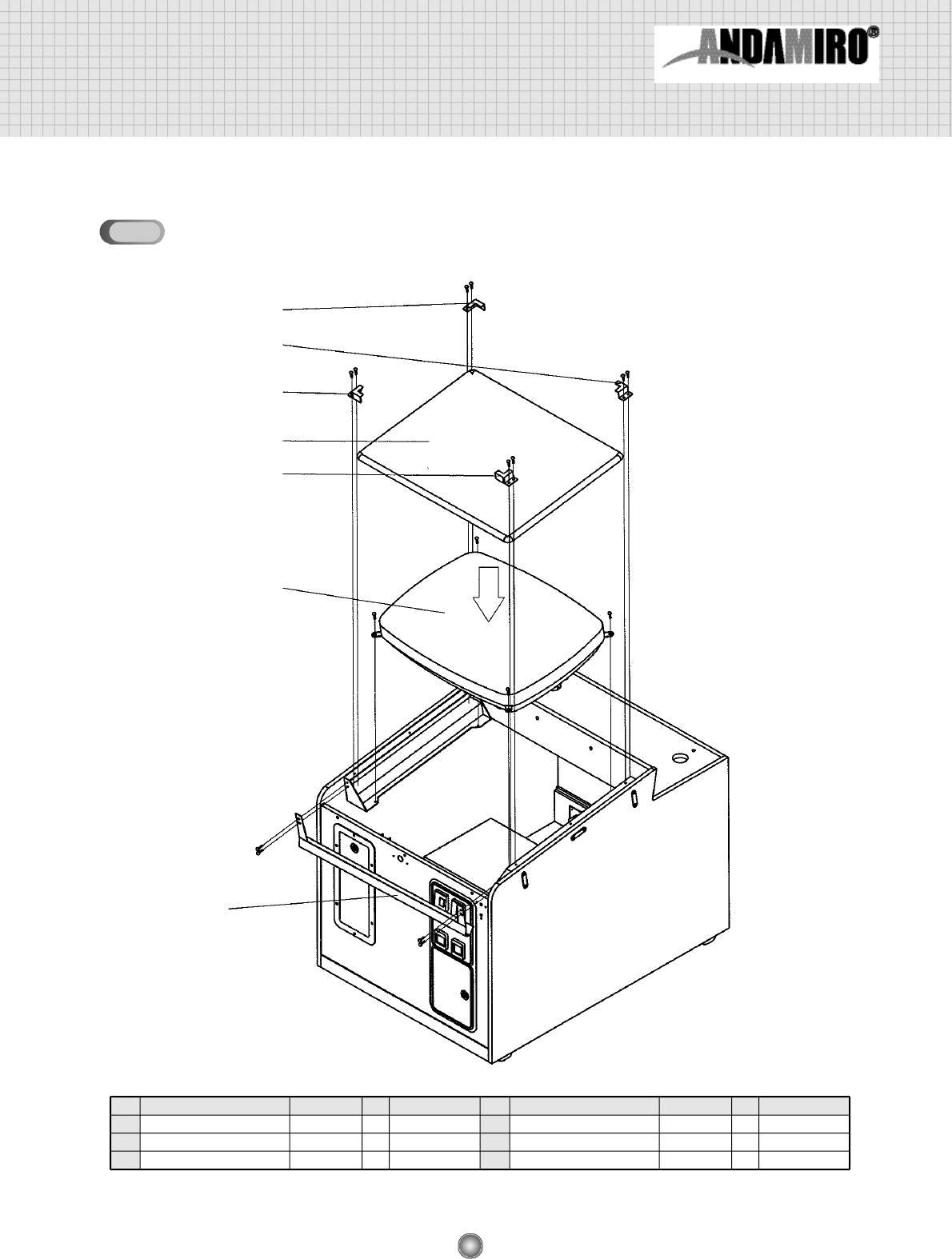
ASSEMBLING CABINET LOW(3)
①
⑤
②
③
④
④
③
NO
①
②
③
NAME SPEC
QTY
CODE NO.
MONITOR
FRONT GLASS
FRONT GLASS SUPPORT-A
CRT CGA 29inch
1
1
2
MZZZ0CRT007
MHAM0GLA001
MHAM0MEP008
NO
④
⑤
NAME SPEC
QTY
CODE NO.
FRONT GLASS SUPPORT-B
SPILL GUTTER
2
1
MHAM0MEP009
MHAT0MEP001
10-3
40
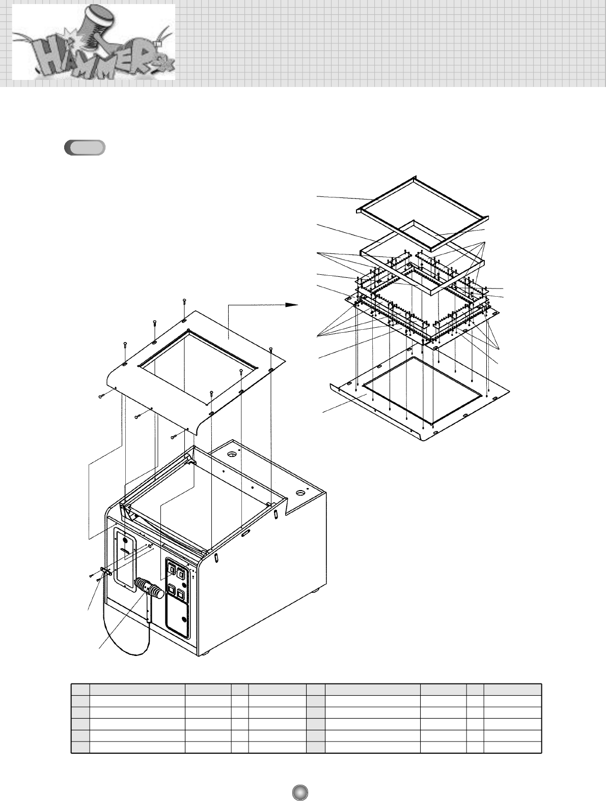
ASSEMBLY DRAWING AND PARTS LIST
ASSEMBLING CABINET LOW(4)
⑦
④
⑥
②
⑤
⑤
③
⑦
④
⑥
⑧
②
①
⑨
⑩
③
NO
①
②
③
④
⑤
NAME SPEC
QTY
CODE NO.
FRONT COVER
SENSOR BRACKET R/L
SENSOR BRACKET UP/DOWN
SENSOR PCB ASS’Y-A
SENSOR PCB ASS’Y-B
EMITION
RECEIVER
1
2
2
7
7
MHAM0MEP007
MHAM0MEP013
MHAM0MEP014
AHAM0PCB009
AHAM0PCB008
NO
⑥
⑦
⑧
⑨
⑩
NAME SPEC
QTY
CODE NO.
SENSOR COVER ACRYL-A
SENSOR COVER ACRYL-B
FRONT GLASS HOLD RUBBER AB
HAMMER HOLD BRACKET
HAMMER ASS’Y
2
2
1
2
1
MHAM0ACR004
MHAM0ACR005
MHAM0RUB004
MHAM0MEP011
AHAM0PLA001
10-4
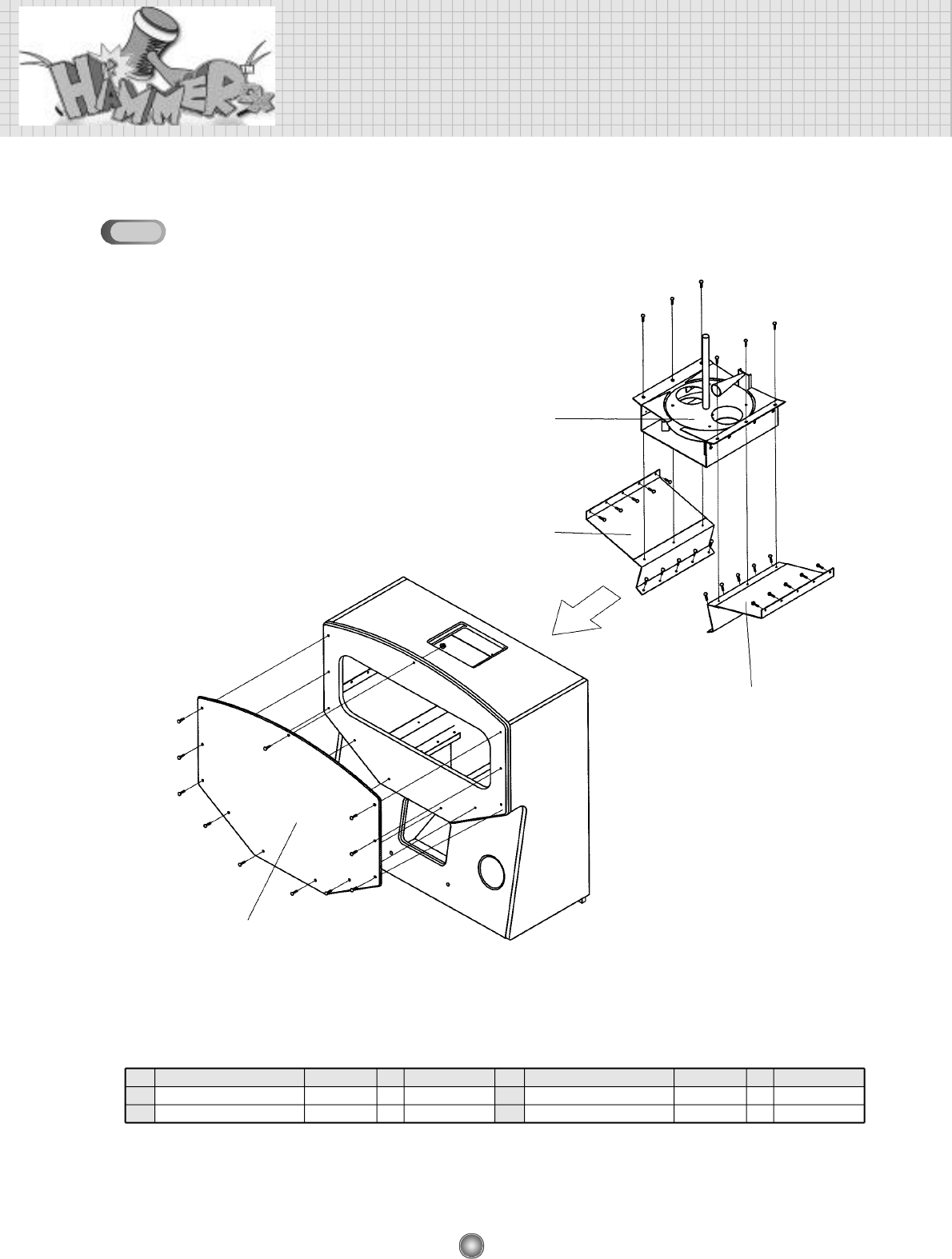
41
ASSEMBLING CABINET UP(1)
NO
①
②
③
NAME SPEC
QTY
CODE NO.
CABINET UP
SPEAKER
LAMP CASE ASS’Y
4 inch
3 0 0 m m
1
2
1
MHAT0WOO001
MZZZ0SPE001
MDRE0PLA008
NO
④
⑤
NAME SPEC
QTY
CODE NO.
INVERTER
CCFL COVER ACRYL
1
1
MELE0INV003
MHAT0ACR003
①
②
③
④
⑤
10-5
42
ASSEMBLY DRAWING AND PARTS LIST
ASSEMBLING CABINET UP(2)
NO
①
②
NAME SPEC
QTY
CODE NO.
CAPSULE DISPENSER ASS’Y
GUIDE BRACKET SUPPORT L
1
1
AHAT0MEP001
MHAM0MEP021
NO
③
④
NAME SPEC
QTY
CODE NO.
GUIDE BRACKET SUPPORT R
FRONT ACRYL
1
1
MHAM0MEP022
MHAT0ACR001
①
②
③
④
10-6
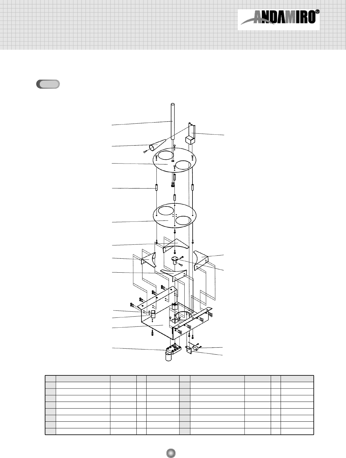
43
ASSEMBLING CAPSULE DISPENSER
NO
①
②
③
④
⑤
⑥
⑦
⑧
NAME SPEC
QTY
CODE NO.
MAIN BRACKET
MOTOR
MOTOR SHAFT
ROTATE SUPPORT BRACKET
BEARING
SWITCH BRACKET
MICRO SWITCH
GUIDE BRACKET L
KGE-3448D 1:615
RW-26
1
1
1
4
4
1
1
2
MHAM0MEP020
MMAL0MOT007
MHAM0PRO003
MHAM0MEP029
MZZZ0BEA031
MHAM0MEP030
MELE0MIC002
MHAM0MEP026
NO
⑨
⑩
⑪
⑫
⑬
⑭
⑮
NAME SPEC
QTY
CODE NO.
GUIDE BRACKET R
ROTATE LOW
SPACE SHAFT
ROTATE UP
MIX SHAFT
BLOCK SPRING BRACKET
BLOCK SPRING
2
1
4
1
1
1
1
MHAM0MEP027
MHAM0MEP024
MHAM0PRO002
MHAM0MEP023
MHAM0PRO001
MHAM0MEP025
MMAL0SPR001
⑬
⑮
⑫
⑪
⑩
⑭
⑧
③
⑦
⑥
⑨
⑨
⑧
⑤
④
①
②
10-7