Arcade Ice Ball Manual Service 11 01 07 User
2015-04-16
User Manual: Arcade Ice Ball Manual
Open the PDF directly: View PDF ![]() .
.
Page Count: 16
1
OWNERS AND SERVICE MANUAL
INNOVATIVE CONCEPTS IN ENTERTAINMENT INC.

2
INTRODUCTION………………………………..……….PAGE 3
· GAME FEATURES
· GAME PLAY
ASSEMBLY………………………………………....……PAGE 4
· BEFORE YOU BEGIN
· TOOLS NEEDED
· INSTALLATION
SET-UP / TESTING………………………………...…...PAGE 5 - 8
· SAFETY PRECAUTIONS
· PROGRAMMING YOUR GAME
· OPTION MODES
· ERROR CODES
· TESTING
QUICK TROUBLESHOOTING………………….……...PAGE 9 - 10
· PROBLEMS AND SOLUTIONS
REPAIR…………………………………………….……..PAGE 11 - 13
· OPERATIONAL BACKGROUND
· MECHANICAL REPAIR
· ELECTRICAL / ELECTRONIC REPAIR
· MAINTENANCE
PARTS LISTINGS……………………………………..…PAGE 14
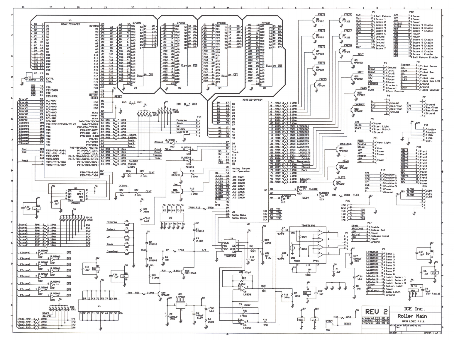
SCHEMATICS………………………………………..…..PAGE 15
TABLE OF CONTENTS
ICEDOC AR9001
REVISION F 11-01-07

3
INTRODUCTION
Another important feature of our game is the operator
selectable “Balls per game”. This feature allows the
operator to control how many balls the game will normally
deliver. This amount is adjustable from 1 to 20 balls per
game. It is however important to note that THE BALLS
PER GAME IS NOT RELATED TO HOW MANY BALLS
ARE IN THE GAME. The quantity of balls in the game is
only for reference based on the normal 9 balls given in
the traditional game. The game will work with 1 to 15 balls
in the game, yet deliver the proper amount programmed
into the game every time. (It is a good idea however to
have at least 3 balls in the game to avoid slow play)
All programming is accomplished from the Main P.C.
Board which is conveniently located at the front end of the
cabinet. This make servicing and adjusting as easy as
turning a key.
GAME PLAY
Game play begins when a player has inserted enough
money into the game to create 1 “Credit”. At this point, the
“Start” button begins to flash.
When the start button is pressed, the balls release from
the game and the game begins.
The player throws balls at the target pockets and is
awarded the points indicated on those pockets.
The player continues to throw balls until they are all used
up. If the player breaks a predetermined score during
game play, he may be entitled to get “Free Balls”.
At the end of the game, the game will dispense tickets
based on score. (If the game is so equipped)
If the player gets a “New High Score” or “Extended Play”
the rotating Beacon light will turn on. The Beacon light will
also turn on if the player has won the ticket jackpot from
the Optional Jackpot Marquee.
GAME FEATURES
Thank you for your purchase of the new ICE BALL™
Alley Roller game from I.C.E. Through extensive testing
and consultation with game operators, we have
developed a game with all of the features and
serviceability you’ve been asking for. We have gone to
great lengths to manufacture an Alley Roller game that is
far easier to service and operate than anything before it.
The features we have added, truly bring this game up to
date.
The game starts off with unparalleled ease of assembly.
The game goes together in just a few minutes.
The game cabinetry is a unique plywood construction with
a special overlay for a superior finish. A special lacquer
finish is applied over the wood for a beautiful rich, deep
look. All of the cabinet panels interlock together, are
reinforced with cleats and are glued together to produce a
cabinet that can handle all of the abuse you can give it.
Loading tickets is a snap, with our easy pull out drawer.
This new feature drastically reduces the time needed to
load tickets, as well as making it much to service ticket
jams or the dispenser.
Long life fluorescent lighting is used throughout the game
to lower maintenance and create a bright playfield area.
Even the ball return area is back lit to add to the
appearance and serviceability of the game.
Reliability is the name of the game with our new ball re-
lease assembly. With a specially engineered solenoid and
double linkages, this mechanism has been tested to last
for years. Best of all, the entire assembly simply lifts out
of the cabinet with no tools needed!
The best state of the art sound on sound audio is used to
create an exciting atmosphere for the game player. Even
our background theme is synchronized so all games play
the theme at the same time, even when only one game is
being played.
ICE BALL™ allows the operator to give the players extra
balls when a certain point threshold is reached. In
addition, double scores can be awarded if desired. This
extends the total points possible and adds a great deal to
player appeal. These features also add excitement when
used in conjunction with the optional Jackpot Marquee.

4
ASSEMBLY
BEFORE YOU BEGIN
WARNING: WHEN INSTALLING THIS GAME,
A 3 PRONG GROUNDED A.C. RECEPTACLE MUST BE
USED. FAILURE TO DO SO COULD RESULT IN
SERIOUS INJURY TO YOURSELF OR OTHERS.
FAILURE TO USE A GROUNDED RECEPTACLE
COULD ALSO CAUSE IMPROPER GAME OPERATION,
OR DAMAGE TO THE ELECTRONICS
DO NOT DEFEAT OR REMOVE THE GROUNDING
PRONG ON THE POWER CORD FOR THE SAME
REASONS AS GIVEN ABOVE. USING AN IMPROP-
ERLY GROUNDED GAME COULD VOID YOUR WAR-
RANTY.
HAVE A QUALIFIED ELECTRICIAN CHECK YOUR A.C.
RECEPTACLE TO BE SURE THE GROUND IS
FUNCTIONING PROPERLY.
TOOLS NEEDED
• Large Allen Key (Supplied)
• Phillips head screwdriver
INSTALLATION
1. Remove the banding from the pallet.
NOTE: BE SURE TO STAND TO THE SIDE WHEN
CUTTING THE BANDS, AS THEY ARE UNDER
PRESSURE, AND COULD SPRING OUT
CAUSING INJURY.
2. Lift out all cage parts as well as any other parts
shipped along with the game.
3. Remove the 2 game halves from the pallet.
4. Set the rear of the game into the approximate location
of where it will be located. If assembling more than 1
game, you must leave space to run the power cords
and linking phone cord.
5. Set the front cabinet into position in front of the rear
cabinet.
6. Open the coin and ticket doors and slide the left side
cover forward enough to connect the harnessing from
the rear cabinet to the front cabinet.
7. Slide the left hand cover back on.
8. Slide the front cabinet into position. Insert the large
Allen key into the holes on the sides of the front cabi-
net and rotate the Allen key 180° to lock the cabinet
halves together.
9. Slide the right hand cover from the game.
10. Remove the packing material from around the ball
release assembly.
NOTE: KEEP THE PACKING MATERIAL FOR THE
BALL RELEASE ASSEMBLY BEHIND THE GAME IN
CASE YOU DECIDE TO MOVE YOUR GAME LATER.
11. Open the parts box containing the balls and install
them into the ball return release. (There should be 9
balls supplied with the game)
12. Slide the right hand cover back onto the game.
13. Open the electronics access door. (Door in between
the ticket and coin drawers)
14. On each Main P.C. Board are 2 modular phone jacks.
Connect a phone line from game to game, plugging 1
end into each game. Feed the phone lines through a
wiring hole located in the rear of the electronic enclo-
sure. It does not matter which jack you plug the
phone line into on the board as long as the phone
lines are connected from game to game. If you are
installing a Jackpot Marquee, it can be connected to
any open phone jack on any game.
15. Connect the long Computer style power cord to the
Power Module. The power module is located inside
the Electronics access door, to the lower right. Con-
nect the other end to a grounded A.C. outlet.*
* Be sure before plugging the game in that it is wired for
the proper A.C. voltage. One way to check is by looking at
the game’s serial number tag. It will indicate the rated
voltage on it. If you are still unsure about what the game’s
voltage is set for, please refer to the “Setting A.C. line
voltages” section in this manual.

5
SET-UP / GAME TESTING
SAFETY PRECAUTIONS
IMPORTANT: FAILURE TO FOLLOW THESE
DIRECTIONS COULD CAUSE SERIOUS DAMAGE TO
YOU OR YOUR GAME.
WARNING: WHEN INSTALLING THIS GAME,
A 3 PRONG GROUNDED A.C. RECEPTACLE MUST BE
USED. FAILURE TO DO SO COULD RESULT IN SERI-
OUS INJURY TO YOURSELF OR OTHERS. FAILURE
TO USE A GROUNDED RECEPTACLE COULD ALSO
CAUSE IMPROPER GAME OPERATION, OR DAMAGE
TO THE ELECTRONICS
DO NOT DEFEAT OR REMOVE THE GROUNDING
PRONG ON THE POWER CORD FOR THE SAME
REASONS AS GIVEN ABOVE. USING AN IMPROP-
ERLY GROUNDED GAME COULD VOID YOUR WAR-
RANTY.
HAVE A QUALIFIED ELECTRICIAN CHECK YOU’RE
A.C. RECEPTACLE TO BE SURE THE GROUND IS
FUNCTIONING PROPERLY.
REPLACE ALL INCANDESCENT BULBS WITH
PROPER ICE SUPPLIED BULBS ONLY
PROGRAMMING YOUR GAME
This section will give you a detailed explanation of the
functions and operating characteristics of each of the
programming buttons.
PLEASE READ THIS SECTION CAREFULLY TO
AVOID PROBLEMS WITH YOUR GAME.
NOTE: THE PROGRAMMING AND TEST BUT-
TONS ARE LOCATED ALONG THE FRONT EDGE
OF THE MAIN P.C. BOARD WHICH IS LOCATED
BEHIND THE ELECTRONICS ACCESS DOOR.
THIS DOOR IS BETWEEN THE TICKET AND COIN
DRAWERS AT THE FRONT OF THE GAME.
PROGRAMMING BUTTON
(PGM / SW1)
This button is used to enter and exit the programming
mode. Use this button to change game settings or to re-
motely change settings on the optional Jackpot Marquee.
Press this button once to enter programming mode. When
in this mode, the game displays will display information
pertinent to game programming. Press this button once
again to exit programming mode.
Once in this mode, you can push SW2, SW3 or SW4 to
make adjustments to the game.
SELECT BUTTON
(SEL / SW2)
This button is used to advance through all of the various
programming option modes. Each push of this button will
move you to the next programmable option. The option
number is displayed in the “Balls Left” display.
STEP UP BUTTON
(UP / SW3)
This button is used to change the VALUE of a particular
option mode. The operation mode values are displayed
on the “Score” display. Each push of this button changes
to the next HIGHER available value for that mode.

6
SET-UP / GAME TESTING
TEST BUTTON
(TEST / SW5)
This button is used for factory burn-in of the game elec-
tronics. It is also very helpful to be sure all game functions
work correctly. When in this mode, the following things
will happen:
• Game release solenoid will cycle on and off
• Displays will count down displaying similar
numbers. (Ex.: all 9’s or 8’s)
• Beacon light will cycle on and off.
• Closing any score (playfield) switch by throw-
ing a ball will create an audible sound.
• Pushing the start button, coin switch or low
ticket micro switch will create an audible
sound.
• Game theme song will constantly play.
To exit the test mode, press the programming button.
OPTIONS MODES
Please the setting information carefully BEFORE making
any adjustments. Failure to set options properly can yield
unexpected results.
PLEASE NOTE: THE VALUES PRE-SET AT THE
FACTORY HAVE BEEN FOUND TO WORK BEST
FOR MOST LOCATIONS.
MODE 00
(VOLUME)
This option is used to change the relative sound volume
of the game. “1” is the lowest the game can be set to play
at while “4” is the loudest. Each time the button is pushed,
a sound is played to make it easier to determine where
the volume level should be set. The factory default for this
option mode is “3”.
MODE 01
(COINS PER CREDIT)
COIN INPUT #1
This mode determines how many coins are needed to
create 1 credit for coin input #1. (This is also the only coin
input normally adjusted for most usage) This value can be
adjusted from 0-8. Setting a “1” would indicate 1 coin is
needed to obtain 1 credit. A “2” would indicate 2 coins are
needed to obtain 1 credit. Setting a “0” sets the game to
the “FREE PLAY” mode. The factory default for this set-
ting is “1”.
MODE 02
(COINS PER CREDIT)
COIN INPUTS #2
This coin input functions in an identical fashion to that of
MODE 01. This option is generally used in markets that
require the use of electronic multi-mechs. Consult our
service department if you have any questions regarding
the use of electronic multi-mechs.
MODE 03
(GAMES PER CREDIT)
This mode can be used to create multiple credits for each
coin inserted. For example: setting a “2” would give you 2
credits for each coin inserted. The range for this option is
0-9. Setting a “0” turns this option off. The default for this
option is “0”.

7
SET-UP / GAME TESTING
MODE 04
(COIN DISCOUNTING)
This option is used to create “Bonus Credits”. The way
this option works is as follows: if a “3” is set, for every 3
coins put in AT THE SAME TIME, 1 extra credit would be
given. The range for this option is 0-9. Setting a “0” turns
this option off. The default value for this option is ”0”.
MODE 05
(BALLS PER GAME)
This option determines the STANDARD amount of balls
dispensed per game. This amount DOES NOT include
any other balls that may be dispensed by other option
settings.
NOTE: THE NUMBER SET WILL DETERMINE
HOW MANY BALLS ARE DISPENSED PER GAME.
THE NUMBER IS NOT DETERMINED BY THE
BALLS KEPT IN THE GAME. THE NUMBER OF
BALLS IN THE GAME IS BASICALLY USED AS A
BALL SUPPLY. THIS AMOUNT SHOULD NOT BE
ALLOWED TO GO BELOW THREE (3) OR ABOVE
FIFTEEN (15).
The range for this option is 0-20. The default value for this
option is “9”. (The traditional balls per game value for al-
ley roller games).
POINT SETTING INFORMATION
IN SOME OF THE MODES BELOW, POINT VALUE
WILL BE DISCUSSED.
THIS GAME HAS THE ABILITY TO BE SET FOR 3
DIFFERENT POINT LEVELS. WHENEVER POINT
VALUES ARE DISCUSSED, THE SIGNIFICANT
(FRONT END NUMBERS) ARE DISCUSSED. THE
TRAILING “00’S” ARE NOT IMPORTANT.
EXAMPLE: SETTING A “30” WOULD BE GOOD
FOR 300 OR 3,000 POINTS. SETTING A 300
WOULD BE GOOD FOR 3,000 OR 30,000 POINTS.
FOR FURTHER INFORMATION CALL:
I.C.E. SERVICE DEPARTMENT
716-759-0360
NORMAL BUSINESS HOURS ARE:
MONDAY – FRIDAY, 9:00 AM TO 6:00 PM EST
MODE 06
(ATTRACT TIME)
This mode will play the game’s “Attract” mode when se-
lected. The attract mode consists of the game’s theme
song being played, along with the beacon light turning on.
The values for this mode (in minutes) is 0-30. Setting a
“0” turns the attract mode off. The default value for this
mode is “3”.
MODE 07
(POINT PER TICKET)
This option adjusts the points needed to dispense a ticket.
Setting a value of 30 will dispense 1 ticket for every 3,000
points scored. The range for this option is 0-9999. The
default value for this mode is “30”. (ticket for every 3,000
points)
MODE 08
(MINIMUM TICKETS)
This mode sets the minimum amount of tickets that can
be dispensed in a game. This would be the equivalent of
a “just for playing” option. This amount set IS NOT in ad-
dition to other tickets won. If the amount of tickets nor-
mally won exceeds the minimum amount set, that number
is the number awarded. The range for this option is 0-10.
Setting a “0” turns this option off. The default value for this
mode is “4”.
MODE 09
(TICKET CAP)
This mode determines the maximum amount of tickets
that can be given in a game REGARDLESS of points
made.
NOTE: THIS MAXIMUM WILL NOT AFFECT THE
TICKETS DISPENSED FOR WINNING THE
TICKET JACKPOT FROM THE OPTIONAL
“JACKPOT MARQUEE”. ANY JACKPOT TICKET
CAP WILL BE HANDLED BY THE JACKPOT MAR-
QUEE.
The range for this option is 0-50. Setting a “0” turns the
option off. The default setting is “0”.

8
SET-UP / GAME TESTING
MODE 10
(THEME PLAY ON)
This mode allows the game’s theme song to be elimi-
nated during game play. Setting a “1” plays the theme
during game play. Setting a “0” turns the theme song off.
It is advisable to leave the song play during the game, as
it adds excitement to the game and speeds up game play.
NOTE: THE GAME’S THEME SONG IS SYNCHRO-
NIZED ON ALL GAMES. WHEN 1 GAME IS
STARTED, THE THEME PLAYS ON ALL GAMES.
THIS PREVENTS SONGS PLAYING AT DIFFER-
ENT TIMES AND THE DISTRACTING NOISES AS-
SOCIATED WITH THAT CONDITION. THIS SYN-
CHRONIZATION DOES NOT AFFECT GAME PLAY
IN ANY WAY AND IS A BENEFICIAL DESIGN
CONSIDERATION.
MODE 11
(FACTORY DEFAULTS)
When this mode is selected, the game will revert to all
factory default settings.
SET “1”, THEN EXIT PROGRAMMING MODE TO
RESET ALL VALUES TO FACTORY DEFAULT.
The default for this mode is “0”.
ERROR CODES
When the game is powered up it will report an error based
on what sensor is bad. It will not continue until the error
has been corrected. This will only occur during power
up. If a sensor becomes blocked after power up, the
game will not detect this as an error.
Error 1 0K Ball Return
Error 2 1K Score Problem
Error 3 2K Score Problem
Error 4 3K Score Problem
Error 5 4K Score Problem
Error 6 10K Right Sensor Problem
Error 7 10K Left Sensor Problem
Error 8 Ball Count Problem
Error 9 Ticket Disconnect
Error 10 Coin Disconnect
Error 11 Coin Switch Stuck
Error 16 Ball Trough not plugged in
TESTING
After the game is installed and set up, it is a good idea to
play a few games, to be sure everything is working prop-
erly.
Play a few games paying special attention to the following
areas:
• Balls per game
• Tickets dispensed
• Beacon light working
• Proper scoring
• Proper jackpot (If using Marquee)
IF YOU HAVE ANY QUESTIONS OR COMMENTS
REGARDING INSTALLATION OR PROPER
FUNCTION OF YOUR GAME, PLEASE CALL OUR
SERVICE DEPARTMENT AT:
I.C.E. SERVICE DEPARTMENT
716-759-0360
NORMAL BUSINESS HOURS ARE:
MONDAY – FRIDAY, 9:00 AM TO 6:00 PM EST

9
QUICK TROUBLESHOOTING
GAME WILL NOT TAKE OR ADD MONEY CORRECTLY
• Micro switch not working or returning properly. Check and repair or replace as necessary.
• Game programming set-up incorrectly. Refer to service manual for proper settings.
• Bad harnessing or connector. Check w/ohm meter and repair if necessary.
• Bad Main P.C. Board. Check and repair or replace as necessary.
START BUTTON WILL NOT FLASH WHEN GAME HAS CREDITS, OR WORK WHEN PUSHED
• Micro switch not working properly. Test and replace as necessary.
• Micro switch popped out of housing. Snap back into housing.
• Burned out light bulb. Replace light bulb.
• Bad harnessing or connector. Check w/ohm meter and repair as necessary.
• Bad Main P.C. Board. Check and repair or replace as necessary.
GAME HAS NO SOUND
• Bad speaker. Check w/ohm meter for 8-ohm load and replace if defective.
• Volume level set incorrectly. Check service manual for volume setting procedures.
• Bad Harnessing or connector. Check w/ohm meter and repair if necessary.
• Bad Main P.C. Board. Check and repair or replace as necessary.
• Main P.C. Board fan bad & I.C.’s overheated. Replace fan.
BALLS WILL NOT RELEASE OR WILL NOT STOP RELEASING
• Solenoid burned out. Replace solenoid.
• Solenoid sticks in. replace solenoid.
• Release lever binding. Check, lubricate or replace as necessary.
• Release return spring broken. Replace spring.
• Bad ball count sensor. Check and replace as necessary.
• Bad connector or harnessing. Check w/ohm meter and repair as necessary.
• Bad Opto-isolator. Check w/ohm meter and replace if necessary.
• Bad Main P.C. Board. Check and repair or replace as necessary.
• Debris jamming ball return system. Clean return area.
GAME WILL NOT ADD POINTS CORRECTLY / COUNTS BALLS WHEN NOT THROWN
• Bad score sensor. Check and repair or replace.
• Score sensor wiring bad. Check w/ohm meter and repair or replace.
• Cabinet harnessing bad. Check w/ohm meter and repair or replace as necessary.
• Sensors loose or misaligned. Realign sensors.
• Main P.C. Board bad. Check and repair or replace as necessary.
TICKET DISPENSER DOES NOT WORK OR WORKS IMPROPERLY
• Bad harnessing. Check w/ohm meter and repair if necessary.
• Bad ticket dispenser. Repair or replace ticket dispenser.
• Dispenser out of tickets. Add tickets.
• Bad Main P.C. Board. Check and repair or replace as necessary.
• Optical sensor on dispenser dirty. Clean sensor.
SCORE DISPLAY WILL NOT LIGHT OR WORKS IMPROPERLY
• No power on Main P.C. Board. Check transformer and fuses / check power module
• Bad connectors or harnessing. Check w/ohm meter and repair as necessary.
• Bad Display P.C. Board. Repair or replace as necessary.
• Bad Main P.C. Board. Repair or replace as necessary.

10
QUICK TROUBLESHOOTING
NO FLUORESCENT LIGHTING
• Bad connectors or harnessing. Check w/ohm meter and repair as necessary.
• Bad ballast transformer. Replace ballast transformer.
• Bad bulb. Replace bulb.
• No A.C. power to game. Check main fuses in power module.
GAME WILL NOT RETAIN HIGH SCORE WHEN GAME TURNED OFF AND THEN BACK ON
• Programming set incorrectly.
• Back up battery on Main P.C. Board bad. Check and replace battery if necessary.
GAMES ACT STRANGELY FOR NO APPARENT REASON
• Game I.D.’s set improperly. Refer to service manual for proper settings.
• Game hit by electrostatic discharge. Turn games off, wait 15 seconds and turn back on.
• Bad Main P.C. Board. Check and repair or replace as necessary.
REFER TO THE NEXT SECTION FOR DETAILED INFORMATION
ON REPLACEMENT OF P.C. BOARDS AND MECHANICAL COMPONENTS

11
GAME REPAIR
WARNING: ALWAYS REMOVE POWER TO THE
GAME BEFORE ATTEMPTING ANY SERVICE,
UNLESS NEEDED FOR SPECIFIC TESTING.
FAILURE TO OBSERVE THIS PRECAUTION
COULD RESULT IN SERIOUS INJURY TO YOUR-
SELF OR OTHERS.
OPERATIONAL
BACKGROUND
The ICE BALL™ game has been designed with
MODULAR repair in mind. The coin drawer and ticket
drawer can be slid out and removed in their entirety to be
worked on in another area if desired. The ball release
assembly can be removed as a unit with no tools
necessary, making repair a snap.
The ball release system utilizes an A.C. Pull tpe solenoid
that has been specifically designed to eliminate residual
magnetism problems commonly found in this type of
solenoid. The solenoid is powered via an Opto-isolator, to
eliminate solenoid noise from the electronic circuitry.
Other than the display, all electronics and power supply
components are located on the Main P.C. Board to make
modular type replacement fast and simple.
The display board has been designed to be very reliable
and easy to repair. Very few drive components are
necessary for this type of display.
TROUBLESHOOTING
PHILOSOPHY
To find problems with the game, always first check what
should be obvious. See that the game is plugged in and
that all of the fuses on the game are good. This includes
the fuse that is located INSIDE the power module.
Next, check to see that all of the connectors are firmly
seated and that none of the wires have pulled out of
them.
When trying to find out if specific components are bad or
not, try swapping them with components from another
player station to see if the problem moves with the com-
ponent, or stays where it was. This will help you to know if
you have a problem with a specific component, or maybe
a problem with either the wiring or the Main P.C. Board.
Use extreme caution when using probes or volt if the
game is powered up. If doing continuity checks, it is im-
portant to disconnect the harnessing at both, as attached
they may yield erroneous results.
If P.C. Boards are suspected as causing problems, check
to see that all of the I.C. chips are firmly seated on the
boards.
If light bulbs are suspected, swap them with one that is
known to work to narrow the problem down to the bulb or
P.C. Board.
MECHANICAL
REPAIR
BALL RELEASE ASSEMBLY
WARNING: BE SURE POWER HAS BEEN REMOVED
FROM THE GAME BEFORE PROCEEDING.
1. Open the cash box drawer at least 6 inches.
2. Pull forward on the ball release cover. (The panel with
the clear plastic window) about 3 inches to disen-
gage, then lift off.
3. Remove the balls from the game.
4. Grasp the release assembly by the rail and slowly lift
out, being careful to avoid hitting the sensors on the
cover retaining screws.
5. Disconnect the connector that connects the release
assembly to the game.
SOLENOID REPLACEMENT
1. Remove the spring from the solenoid and mounting
bolt.
2. Remove the cotter pin from the clevis pin and slide
the clevis pin from the solenoid shaft and linkage.

12
GAME REPAIR
3. Carefully scribe a mark when removing the solenoid
to be sure the replacement is properly located.
4. Remove the hardware that secures the solenoid to
the mounting plate.
5. When re-assembling, be sure to use the same size
cotter pin to retain the clevis pin, as this pin is needed
to hold the spring to the solenoid assembly.
6. Be sure the bent over end of the cotter pin is trimmed
so it cannot contact the solenoid body.
SOLENOID REPLACEMENT
1. The ball count sensor must be replaced as an assem-
bly. Remove the transmitter, receiver and sensor P.C.
Board from the release assembly.
2. When replacing the unit, it is important to remember
to use the star washers. This will prevent the sensors
from rotating or loosening.
3. Be sure to install the new sensors in the same posi-
tion as the old ones. This is important to insure proper
alignment and consequently proper ball count
BULB REPLACEMENT
1. The bulbs replace easily. Pull the bulb straight out of
the socket.
2. Insert the new bulb into the socket and snap into
place.
ELECTRONIC REPAIR
DISPLAY ASSEMBLY
SCORE DISPLAY ASSEMBLY
1. Unlock and remove the display cover.
2. Lift the entire assembly straight up, then pull the bot-
tom forward and remove connectors from the rear.
3. Unscrew the display from the mounting bracket.
4. Assemble in reverse order.
BULB REPLACEMENT
1. Unlock and remove the display cover.
2. Pull the old bulb straight out of the socket.
3. Push a new bulb straight into the socket and snap
into place.
MAIN P.C. BOARD
1. Turn off A.C. power and remove the power cord from
the power module.
2. Remove all P.C. Board connectors noting where each
one connects into the board.
3. Remove the 4 hex fasteners that retain the board to
the mounting bracket.
4. Re-assemble in reverse order.

13
GAME REPAIR
BALL RETURN SENSOR
1. Turn off game power.
2. Open cash drawer at least 6 inches.
3. Slide ball release cover from right hand side of game.
4. Sensor assembly is located at the rear of the ball re-
turn channel where the 2 cabinets meet.
5. Unscrew the sensor assembly and remove.
6. Assemble in reverse order.
NOTE: BE SURE THE TRANSMITTER WIRING IS
KEPT HIGH ENOUGH FOR THE BALLS TO PASS
UNDER. IF THERE IS ANY SLACK, IT IS IMPOR-
TANT TO REMOVE IT USING A TIE WRAP, ETC.
SCORE SENSORS
1. Remove all A.C. power from the game.
2. Remove the 6 screws from the front of the cage and
remove the front of the cage.
3. Remove the single screw from the bottom of each
cage side and remove the sides.
4. Remove the 2 retaining screws on the playfield.
5. Remove the playfield.
6. Re-connect power to the game and put the game in
test mode.
7. Run your hand through each sensor pair and listen for
the sound to indicate proper function.
8. If the sensor does not indicate proper function, re-
move the sensor and replace.
9. Re-assemble in reverse order.
10. Re-test the assembly when finished.
MAINTENANCE
Maintenance is easy as the game requires very little ser-
vice under normal use. To get the best out of the game,
please perform the following as indicated:
• Clean the playfield weekly using Wildcat pinball
cleaner.
• Clean the playfield once every 3 months with a buff-
ing wheel and Novus polish.
• Oil the levers and linkages on the release system
every 6 months.
• Polish the cabinet with a good grade of spray furniture
polish every 6 months.

14
PARTS LISTINGS
MECHANICAL PARTS
AR1001 Ball Rail
AR1002 Ball Return Tray
AR1003 Rail Support Spacer
AR1004 Ball Release Lever Spring
AR1005 Cash Box
AR1007 Solenoid Linkage
AR1009 Ball Release Lever Bracket
AR1011 Channel Cover, LEFT
AR1012 Channel Cover, RIGHT
AR1016 Alley Edge Protector, REAR
AR1018 Ball Release Lever
AR1019 Alley Edge Protector, FRONT
AR1020 Cup Connecting Plates
1024 Ticket Bin
1026 Ticket Bin Switch Mounting Bracket
AR1029 Speaker Grille
AR1033 Cage, LEFT SIDE
AR1034 Cage, RIGHT SIDE
AR1035 Cage, FRONT
AR2017 Diffuser Support
AR3000 Runaway Material w/Adhesive
AR3001 Ball Jump
AR3005 Ball Cover Window
AR3006 Playfield Light Cover
AR3008 PL7 Light Diffuser
AR3010 Cup, 10,000 Point
AR3011 Cup, 5,000 Point
AR3012 Cup, 4,000 Point
AR3013 Cup, 2,000 and 3,000 Point
AR3014 Cup, 1,000 Point
AR3015 Cup, Bottom Ring
AR3017 Insulating Grommet
AR3020 Runaway Ball Bumper Material
AR3021 Ball Stop Grommet
AR3024 Ball
AR3065 Runaway Ball Bumper Cap, Left Side
AR3066 Runaway Ball Bumper Cap, Right Side
AR3069 Ball Diverter
5014 Coin Door Lock
5101 Mech Holder
6105 Latch Tool
6111 Fiber Lever Washer
6117 Clevis Pin 3/4”
6118 Clevis Pin 1”
GRAPHICS & DECALS
AR7201 Display Panel
AR7221 Programming Decal (Part 1)
AR7222 Programming Decal (Part 2)
AR7003 Coin Door Decal
AR7004 Ticket Door Decal
AR7008 Instruction Panel
RB7009 Fuse Rating Decal
AR7014 10,000 Point Decal, Left Hand Side
AR7015 5,000 Point Decal
AR7016 4,000 Point Decal
AR7017 3,000 Point Decal
AR7018 2,000 Point Decal
AR7019 1,000 Point Decal
AR7020 10,000 Point Decal, Right Hand Side
AR9001 Service Manual
ELECTRICAL / ELECTRONIC
PARTS
211 Low Ticket Switch
248 PL7 Transformer
249 PL7 Bulb
251 PL7 Socket
DA2033X PCBA - (Small Display)
RB2032X PCBA - (Large Display)
DA2002X Transformer
AR2005 Start Button
HP2006B Blue Rotating Beacon Light
AR2007 Speaker 6 X 9
AR2008 Solenoid
RB2009AX PCBA - (Opto Sense Point)
RB2009BX PCBA - (Opto Sense Point Zero)
RB2009CX PCBA - (Opto Sense Ball Count)
RB2009X PCBA - (Opto Sense Point 10K)
CC2027 20 Ft. Computer Style Power Cord
AR2028X Ball Eject P.C. Board (AR Model)
RB2034X Main P.C. Board Assembly
DD2007X Power Module
2111 Solid State Relay
2426 12 Ft. Modular Phone Cord
HH5005 Ticket Dispenser (Entropy)
PC20224 Counter, 12 Volt D.C.
PC20429 Red Diffused L.E.D.
15
Contacts at SEGA
Machine Sales
Telephone: +44 (0) 208 391 8090
Fax: +44 (0) 208 391 8099
www.sega-amusements.co.uk
SEGA Spares
Telephone: +44 (0) 208 391 8060
Fax: +44 (0) 208 391 8096
www.segatotalsolutions.com
Customer Services
Telephone: +44 (0) 208 391 8065
Fax: +44 (0) 208 391 8096
