Arcade Initial D 3 Twin Manual 0 D3 Manual_Rev User
Initial D 3 Twin Manual Initial D 3 TWIN Manual Initial D 3 TWIN Manual sharedfiles soe-web-arcade2-pub
2013-11-20
User Manual: Arcade Initial D 3 Twin Manual 0
Open the PDF directly: View PDF ![]() .
.
Page Count: 144 [warning: Documents this large are best viewed by clicking the View PDF Link!]
420-6799-02UK REV 0
SERVICE MANUAL
TWIN TYPE
Before using this product, read this SERVICE MANUAL carefully to understand the contents stated herein.
After reading this manual, be sure to keep it available nearby the product or somewhere convenient in
order to be able to refer to it whenever necessary.
Manufactured in the UK by
2
CONTENTS
1. BEFORE USING THIS PRODUCT .......................................................................................................5
1.1. INSPECTIONS IMMEDIATELY AFTER TRANSPORTING THE PRODUCT TO THE LOCATION ......... 6
2. INTRODUCTION TO THIS SERVICE MANUAL...................................................................................8
3. INSTALLATION AND SERVICE INSTRUCTIONS ...............................................................................9
3.1. HANDLING AND INSTALLATION PRECAUTIONS ................................................................................. 9
3.2. COIN HANDLING ................................................................................................................................... 11
3.3. NAME OF PARTS................................................................................................................................... 12
3.4. ACCESSORIES ...................................................................................................................................... 13
3.5. SHIPPING THE GAME BOARD ............................................................................................................. 14
3.6. SHIPPING THE GD-ROM DRIVE........................................................................................................... 15
3.7. ASSEMBLY INSTRUCTIONS................................................................................................................. 16
3.7.1. APPLYING THE PLAY INSTRUCTIONS .................................................................................17
3.7.2. ASSEMBLING THE COCKPIT .................................................................................................18
3.7.3. SECURING IN PLACE (LEG ADJUSTER ADJUSTMENT) .....................................................19
3.7.4. BILLBOARD INSTALLATION ...................................................................................................21
3.7.5. INSTALLING THE AC COVERS (WIRE COVERS ) ................................................................23
3.7.6. COIN HANDLING INSTALLATION...........................................................................................24
3.7.6.1. WIRING CONNECTIONS..................................................................................................25
3.7.7. COMMUNICATION CABLES ...................................................................................................26
3.7.8. CONNECTION TO THE POWER SUPPLY .............................................................................27
3.7.9. ASSEMBLY CHECK .................................................................................................................30
3.7.10. MOVING THE MACHINE ......................................................................................................32
3.8. FUSES.................................................................................................................................................... 33
3.9. MAINTENANCE...................................................................................................................................... 34
3.9.1. HANDLE MECHA .....................................................................................................................34
3.9.1.1. REPLACING AND ADJUSTING THE HANDLE MECHA’S VR ........................................35
3.9.1.2. GREASING........................................................................................................................36
3.9.2. CARD READER/WRITER UNIT ...............................................................................................37
3.9.2.1. SETTING DEDICATED CARDS........................................................................................37
3.9.2.2. HEAD CLEANING .............................................................................................................39
3.9.2.3. CLEARING CARD JAMS ..................................................................................................40
3.9.3. ACCELERATOR & BRAKE ......................................................................................................41
3.9.3.1. Removing the Accelerator & Brake. ..................................................................................41
3.9.3.2. Adjusting the V.R. ..............................................................................................................42
3.9.3.3. Replacing the V.R..............................................................................................................43
3.9.3.4. Greasing ............................................................................................................................43
3.9.4. SHIFT LEVER...........................................................................................................................44
3.10. REPLACEMENT OF FLUORESCENT LAMP AND OTHER LAMPS ................................................. 45
3.10.1. FLUORESCENT LAMP REPLACEMENT ............................................................................45
3.10.2. START BUTTON LAMP REPLACEMENT............................................................................46
3.10.3. CLEANING THE CABINET SURFACES ..............................................................................47
3.10.4. SEAT (Greasing to Seat Rail Portion)...................................................................................47
3.11. TROUBLESHOOTING ........................................................................................................................ 48
3.11.1. CARD READER/WRITER.....................................................................................................48
3.11.2. TROUBLESHOOTING (WHEN NO ERROR MESSAGE IS SHOWN).................................51
3.12. GAMEBOARD..................................................................................................................................... 54
3.12.1. REMOVING THE BOARD.....................................................................................................54
3.12.2. REMOVING THE GD-ROM DRIVE ......................................................................................55
3.12.3. REMOVING THE GAME BOARD .........................................................................................55
3.12.4. MACHINE SET UP................................................................................................................56
3.12.4.1. SETTING FOR COMMUNICATION PLAY........................................................................57
3.13. PERIODIC CHECK AND INSPECTION.............................................................................................. 58
4. HOW TO PLAY....................................................................................................................................59
4.1. GAME DESCRIPTION............................................................................................................................ 59
4.1.1. Game Overview ........................................................................................................................59
4.1.1.1. Legend of the Streets ........................................................................................................59
4.1.2. Game Flow................................................................................................................................60
4.1.2.1. Challenger Accept Screen, Battle Race Select Screen: ...................................................60
4.1.2.2. Card Entry Screen and Card Purchase Screen: ...............................................................60
4.1.2.3. Card Data Check Screen:..................................................................................................60
4.1.2.4. Vehicle Selection Screen:..................................................................................................61
4.1.2.5. Transmission Selection Screen: ........................................................................................61
3
4.1.2.6. Parts Course Selection Screen: ........................................................................................61
4.1.2.7. Time Attack........................................................................................................................65
4.1.2.8. The BUNTA Challenge! .....................................................................................................65
4.1.2.9. Network Battle Race ..........................................................................................................65
4.1.2.10. Configuration .....................................................................................................................68
4.1.2.11. Game Over ........................................................................................................................69
4.1.2.12. Transferring Old Card Data ...............................................................................................69
4.1.2.13. Limit on Card Use..............................................................................................................70
4.1.2.14. Car Selections ...................................................................................................................71
4.1.2.15. Race Courses....................................................................................................................71
4.1.2.16. Legend of the Streets Rival Characters ............................................................................72
5. MAINTENANCE INSTRUCTIONS ......................................................................................................73
5.1. EXPLANATION OF TEST AND DATA DISPLAY ................................................................................... 73
5.1.1. VTS ASSEMBLY.......................................................................................................................74
5.2. SYSTEM TEST MODE ........................................................................................................................... 75
5.2.1. RAM TEST................................................................................................................................76
5.2.2. JVS TEST .................................................................................................................................76
5.2.3. SOUND TEST...........................................................................................................................77
5.2.4. C.R.T TEST ..............................................................................................................................77
5.2.5. SYSTEM ASSIGNMENTS ........................................................................................................78
5.2.5.1. COIN ASSIGNMENTS.......................................................................................................78
5.2.5.2. COIN/CREDIT SETTING (COIN CHUTE COMMON TYPE) ............................................79
5.2.5.3. COIN/CREDIT SETTING (COIN CHUTE INDIVIDUAL TYPE).........................................80
5.2.5.4. MANUAL SETTING ...........................................................................................................81
5.2.5.5. SEQUENCE SETTING......................................................................................................82
5.2.5.6. BOOKKEEPING ................................................................................................................83
5.2.5.7. BACKUP DATA CLEAR ....................................................................................................83
5.2.5.8. ROM BD TEST ..................................................................................................................84
5.2.5.9. CLOCK SETTING..............................................................................................................84
5.3. GAME TEST MODE ............................................................................................................................... 85
5.3.1. GAME TEST MENU MODE......................................................................................................85
5.3.2. INPUT TEST .............................................................................................................................86
5.3.3. OUTPUT TEST .........................................................................................................................87
5.3.4. FORCE FEEDBACK .................................................................................................................88
5.3.5. INPUT ASSIGNMENTS ............................................................................................................89
5.3.6. GAME ASSIGNMENTS ............................................................................................................91
5.3.7. CARD R/W TEST......................................................................................................................92
5.3.8. CLEANING PROCESS.............................................................................................................94
5.3.9. CLOSE SETTING .....................................................................................................................95
5.4. BOOKKEEPING...................................................................................................................................... 97
5.4.1. BACKUP DATA CLEAR..........................................................................................................101
6. COIN MECH INSTALLATION AND CREDIT BOARD SET UP ........................................................102
6.1. INTRODUCTION .................................................................................................................................. 102
6.1.1. PRICE OF PLAY SETTINGS UK ...........................................................................................104
6.1.2. PRICE OF PLAY SETTINGS EURO......................................................................................105
6.1.3. PRICE OF PLAY SETTINGS Austria-Czech-Denmark-Norway-Israel-France2...................106
7. DESIGN RELATED PARTS ..............................................................................................................107
8. PARTS LIST ......................................................................................................................................108
8.1. ASSEMBLY STRUCTURE ................................................................................................................... 108
8.2. TOS-00001UK TOP ASSY INITIAL D 3 TWIN ..................................................................................... 109
8.3. TOS-0200UK ASSY BILLBOARD......................................................................................................... 111
8.4. TOT-0400UK ASSY AC BRKT MAIN ................................................................................................... 112
8.5. TOT-0700UK ASSY AC BRKT SUB ..................................................................................................... 113
8.6. TOT-1200UK ASSY PEDAL BASE TOT .............................................................................................. 114
8.7. ASSY ACCEL & BRAKE (SPG2200).................................................................................................... 115
8.8. FZR-1550UK ASSY MONITOR COVER L 2P ...................................................................................... 117
8.9. FZR-1555UK ASSY MONITOR COVER R 2P ..................................................................................... 117
8.10. TOS-1600UK ASSY SEAT TWIN 1P ................................................................................................ 118
8.11. TOF-2000XUK ASSY CONTROL PANEL ........................................................................................ 120
8.12. TOS-2150UK ASSY SW PLATE....................................................................................................... 122
8.13. TOF-2500 ASSY HANDLE MECHA.................................................................................................. 123
8.14. TOS-4500UK ASSY MAIN BD .......................................................................................................... 125
8.15. TOT-4600UK ASSY ELEC BD.......................................................................................................... 126
8.16. TOS-10001UK ASSY COCKPIT 1P.................................................................................................. 127
4
8.17. APC-1560 ASSY SPEAKER L ......................................................................................................... 130
8.18. APC-1565 ASSY SPEAKER R ........................................................................................................ 130
8.19. ORT-1120UK ASSY SUB MAIN BASE............................................................................................. 131
8.20. FRI-0300UK ASSY COINCHUTE TOWER FRI ................................................................................ 131
8.21. FRI-1510UK ASSY BASE LID R....................................................................................................... 132
8.22. SPG-0500UK ASSY WIRE COVER SPG TWIN ............................................................................... 133
8.23. VOF-0450UK CARD UNIT TWIN L................................................................................................... 134
8.24. VOF-0460UK CARD UNIT TWIN R .................................................................................................. 135
8.25. TOS-INST-TW ASSY INSTALLATION KIT TOS TWIN .................................................................... 136
9. APPENDIX A - ELECTRICAL SCHEMATIC .....................................................................................137
9.1. WIRE COLOURS.................................................................................................................................. 137
9.2. ELECTRICAL SCHEMATIC.................................................................................................................. 137

5
1. BEFORE USING THIS PRODUCT
To ensure the safe usage, be sure to read the following before using the product. The following instructions are
intended for the use of QUALIFIED SERVICE PERSONNEL ONLY.
If any activity is carried out on the product, this should be done only after carefully reading and sufficiently
understanding the instructions.
Only qualified service personnel should carry out maintenance on the product.
Depending on the potential risk, terms such as” WARNING!” “CAUTION” and “IMPORTANT!” are used where an
explanation is given that requires special attention. SEGA is not responsible for injury or damage caused by use in a
manner contrary to the instructions given in this document.
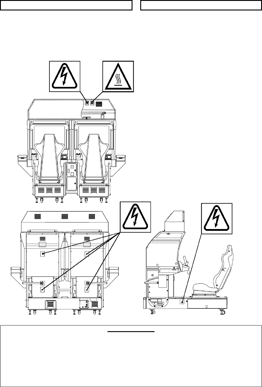
In order to prevent accidents warning stickers and printed instructions are applied in the places where a potentially
hazardous situation relating to the product could arise. Be sure to comply with these warnings.
Indicates that mishandling the product by disregarding this warning will cause a potentially
hazardous situation that can result in death or serious injury.
Indicates that mishandling the product by disregarding this caution will cause a potentially
hazardous situation that can result in personal injury and or material damage.
This is cautionary information that should be complied with when handling the product.
Indicates that mishandling the product by disregarding this will cause a potentially hazardous
situation that may not result in personal injury but could damage the product.
Be sure to turn off the power and disconnect from the mains supply before working on the machine.
Ensure that the correct fuses are fitted to the machine. Details of these are enclosed in the Service Manual.
Ensure that only qualified Service Engineers perform any maintenance work on the machine.
Specification changes, removal of equipment, conversion and/or additions not designated by SEGA are not permitted
and will invalidate this product’s CE conformity.
Warning labels or safety covers for personal protection etc, are component parts of the product. A potential hazard will
be created if the machine is operated while any parts have been removed. Do not operate the product if any doors, lids
or protective covers become damaged or lost. SEGA is not liable in any whatsoever for any injury and/or damage
caused by specification changes not designated by SEGA.
Before installing the product, check for the Electrical Specification Sticker, SEGA products have a sticker on which the
electrical specifications are detailed. Ensure that the product is compatible with the power supply voltage and frequency
requirements of the location in which the machine is to be installed.
Install and operate the machine only in places where appropriate lighting is available, allowing warning stickers to be
clearly read.
To ensure maximum safety for customers and operators, stickers and printed instructions describing potentially
hazardous situations are applied to potentially hazardous locations. Ensure that the product’s operating location has
sufficient lighting to allow any warnings to be read. If any sticker or printed warning is removed or defaced, do not
operate the machine until an identical item has replaced it.
Exercise great care when handling the monitor (applies only to product with monitor). Some of the monitor (TV) parts
are subject to high-tension voltage. Even after turning the power off some components are liable to high-tension
voltage. Only qualified service engineers should perform monitor repair and replacement.
In cases where commercially available monitors and printers are used, only the items relating to this product are
contained in this manual. Some commercially available equipment will have functions and reactions not referred to in
this manual. This manual should be read in conjunction with the specific manufacturer’s manual for such equipment.
Descriptions contained herein may be subject to change without prior notification.
The contents described herein are fully prepared with due care. However, should any question arise or errors be found
please contact SEGA AMUSEMENTS EUROPE LTD.
Descriptions contained herein may be subject to change without prior notification.
The contents described herein are fully prepared with due care. However, should any question arise or
errors be found please contact SEGA.

6
1.1. INSPECTIONS IMMEDIATELY AFTER TRANSPORTING THE PRODUCT
TO THE LOCATION
• Only QUALIFIED SERVICE PERSONNEL should carry out inspection.
Normally, at the time of shipment, SEGA products are in a state to allowing usage immediately after
transporting to the location. Nevertheless, an irregular situation may arise during transportation preventing
this. Before turning on the power, check the following points to ensure that the product has been
transported safely.
• Are then any dented parts or defects (cuts, etc.) on the external surfaces of the product?
• Are castors and leg adjusters present and undamaged?
• Do the power supply voltage and frequency requirements meet with the local supply?
• Are all wiring connectors correctly and securely connected? Unless connected in the correct direction,
connector connections cannot be made successfully. Do not insert connectors forcibly.
• Are all IC’s of each IC BD firmly inserted?
• Does the power cord have any cuts or dents?
• Do fuses meet the specified rating?
• Are such units such as monitors, control equipment, IC BD, etc. firmly secured?
• Are all earth wires connected?
• Are all accessories available?
• Can all doors and lids be opened with the accessory keys and/or tools?
7
CONCERNING THE STICKER DISPLAY CONCERNING WARNING STICKERS
SEGA product has stickers describing the product
manufacture number (Serial Number) and
electrical specification. If you require service
assistance you will require the Serial Number.
Identical machines may have different parts fitted
internally. Only by quoting the Serial Number will
the correct parts be identified.
SEGA product has warning displays on
stickers, labels or printed instructions
adhered/attached to or incorporated in the
places where hazardous situations can arise.
The warning displays are intended for the
accident prevention of customers and service
personnel.
SPECIFICATIONS
Installation Space (cm): 202 x 170
Height (cm): 190
Weight (kg): 492
Power consumption (max): Rated Voltage (V.AC): 230 ±10%
Rated Current (A): 2.75
Note: Descriptions in this manual are subject to change without prior notice.
8
2. INTRODUCTION TO THIS SERVICE MANUAL
SEGA ENTERPRISES LTD. supported by its experience in electronic high technology of VLSI’s,
microprocessors etc. and with a wealth of experience, has for more than 30 years been supplying various
innovative and popular games to the world market. This Service Manual is intended to provide detailed
descriptions together with all the necessary information covering the general operation of electronic
assemblies, electro-mechanicals, servicing controls, spare parts, etc. as regards this new SEGA product.
This manual is intended for those who have knowledge of electricity and technical expertise especially in
IC’s, CRT’s, microprocessors etc. Carefully read this manual to acquire sufficient knowledge before
working on the machine. Should there be any malfunction, non-technical personnel should under no
circumstances touch the internal systems. Should such a situation arise contact our head office.
SEGA AMUSEMENTS EUROPE LTD./ SEGA SERVICE CENTRE
Suite 3a
Oaks House
12 - 22 West Street
Epsom
Surrey
United Kingdom
KT18 7RG
9
3. INSTALLATION AND SERVICE INSTRUCTIONS
• Only QUALIFIED SERVICE PERSONNEL should carry out installation and
commissioning.
3.1. HANDLING AND INSTALLATION PRECAUTIONS
When installing or inspecting the machine, be very careful of the following points and pay attention to
ensure that the player can enjoy the game safely.
The game must NOT be installed under the following conditions:
• Outside, the game is designed for indoor use only.
• In areas directly exposed to sunlight, high humidity, dust, excessive heat, or extreme cold.
• In locations that would present an obstacle in the case of an emergency i.e. near fire equipment or
emergency exits.
• On unstable surfaces or surfaces subject to vibration.
• Where liquids, other than routine cleaning, may come into contact with the game.
Important:
• Only Qualified Service Personnel should install this machine.
• Be sure to switch the supply power OFF and remove the mains supply plug from the machine before
any work is carried out on the machine.
• Do not attempt to repair the PCB’s (Printed Circuit Boards) yourself. This will void the warranty. The
PCB’s contain static sensitive devices that could be damaged.
• Always return a faulty part to your distributor with adequate packaging and protection.
• When removing the plug from the mains always grasp the plug not the cable.
• Do not use a fuse that does not meet the specified rating.
• Make sure all connections are secure before applying power.
10
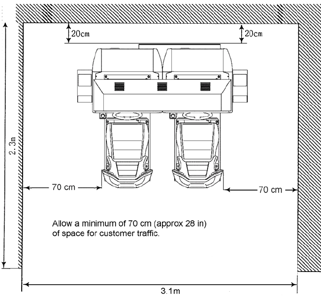
Installation Space

11
• Ensure that the mains lead is not damaged. If the mains lead is damaged in any
way there could be a danger of electric shock or a fire hazard.
• Ensure that the power supply is fitted with circuit protection. Using the power
supply without circuit protection is a fire hazard.
3.2. COIN HANDLING
Standard Sega machines are fitted with a SR3 coin mechanism, however, as a service to our customers
Sega machines can be supplied with no coin mechanism or door allowing the customer to fit a coin
handling option from the approved list. Fit only the coin handling arrangements detailed below and follow
the instructions provided in Section 3.7.6. Failure to fit the coin handling options detailed or failure to follow
the installation instructions will render the machine, under the CE marking directive, void.
Approved coin handling options:
• Coin controls SR3
• Generic mechanical
• Mars (MS111B1 and ME115)
• SECI RM4-G20
12
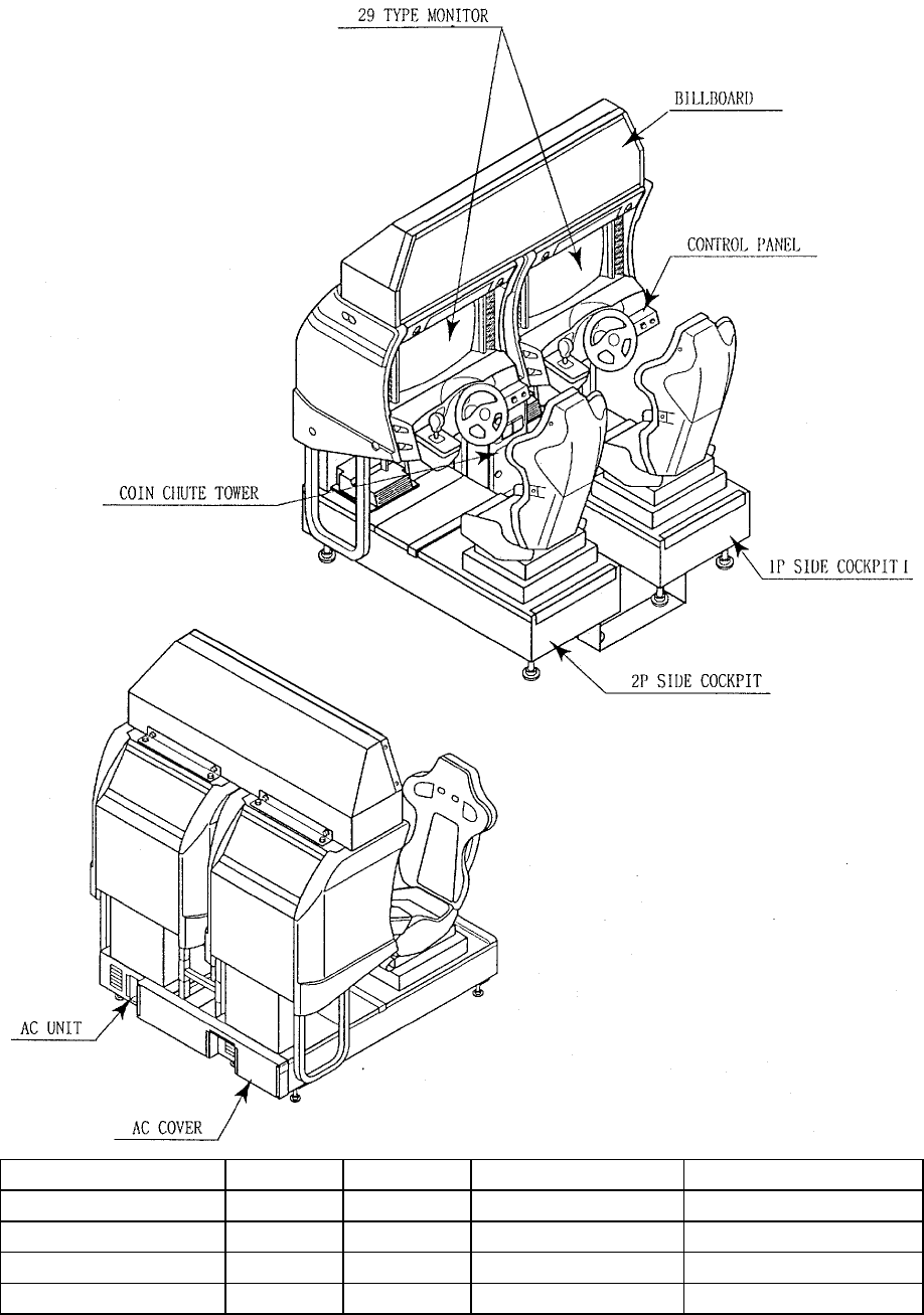
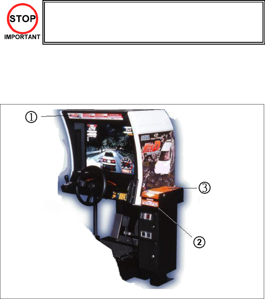
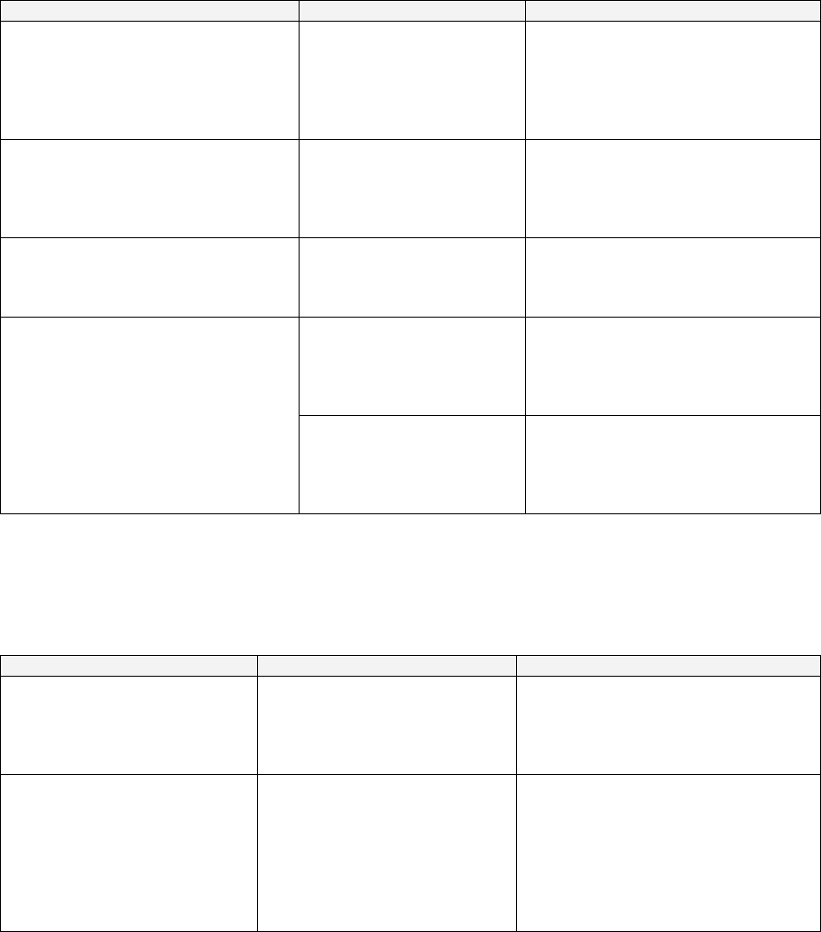
3.3. NAME OF PARTS
Width (cm) Length (cm) Height (cm) Weight (kg)
COCKPIT (EACH) 101 165 152 224
COIN CHUTE TOWER 27 33 57 15
BILLBOARD 161 36 39 25
When Assembled 202 170 190 492 approx
WITH CARD READ/ WRITE UNIT (NOT SHOWN)

13
3.4. ACCESSORIES
The machine is supplied with an installation kit. Please ensure the following parts are supplied:
ITEM PART NO. QTY DESCRIPTION
1 TOS-0200UK 1 ASSY BILLBOARD
2 FRI-0300UK 1 ASSY COINCHUTE TOWER FRI
3 SPG-0500UK 1 ASSY WIRE COVER SPG TWIN
4 DYN-0013 1 JOINT PIPE
5 DYN-0006XUK 1 AC COVER B
6 SRT-0018UK 1 AC COVER C
7 DYN-0019UK 1 AC COVER D
9 SPG-0008 2 BILLBOARD HOLDER
10 422-0924UK 2 PLAY INSTR SH TOS MULTI
13 PK0358 1 INST KIT BOX TOS TWIN
14 TOS-0004UK 2 STICKER CARD SLOT TOF A MULTI
15 TOT-0005UK 2 STICKER CARD SLOT TOF B MULTI
16 601-11358-01 3 CARD PACKAGE TOS ENG
17 601-11050-91 1 CLEANING KIT(30SHT)
18 220-5753 1 VOL CONT B-5K OHM (TOCOS)
101 440-CS0186UK 2 STICKER C EPILEPSY MULTI
201 030-000825-SB 20 M8X25 BLT W/S BLK
202 068-852216-0B 20 M8 WSHR 22OD FLT BLK
203 000-P00412-WB 15 M4X12 MSCR PAN W/FS BLK
204 050-F00400 3 M4 NUT FLG SER PAS
205 068-441616 3 M4 WSHR 16OD FLT PAS
401 420-5827 1 SERVICE MANUAL SANWA 31K
402 420-6799-02UK 1 SERVICE MANUAL TOS TWIN
403 OS1019 2 SELF SEAL BAG 9X12.3/4
404 540-0006-01 1 WRENCH M4 TMP PRF
405 540-0007-01 1 WRENCH M5 TMP PRF
406 540-0009-01 1 WRENCH M8 TMP PRF
407 220-5484 1 VOL CONT B-5K OHM
408 SAECE-xxx 1 DECLARATION OF CONFORMITY
409 514-5078-5000 2 FUSE 5X20 CERAMIC SB 5000mA
411 420-6620UK 1 SERVICE MANUAL GD ROM SYSTEM
416 509-5704 1 SW MICRO TYPE (OMRON K3L13)
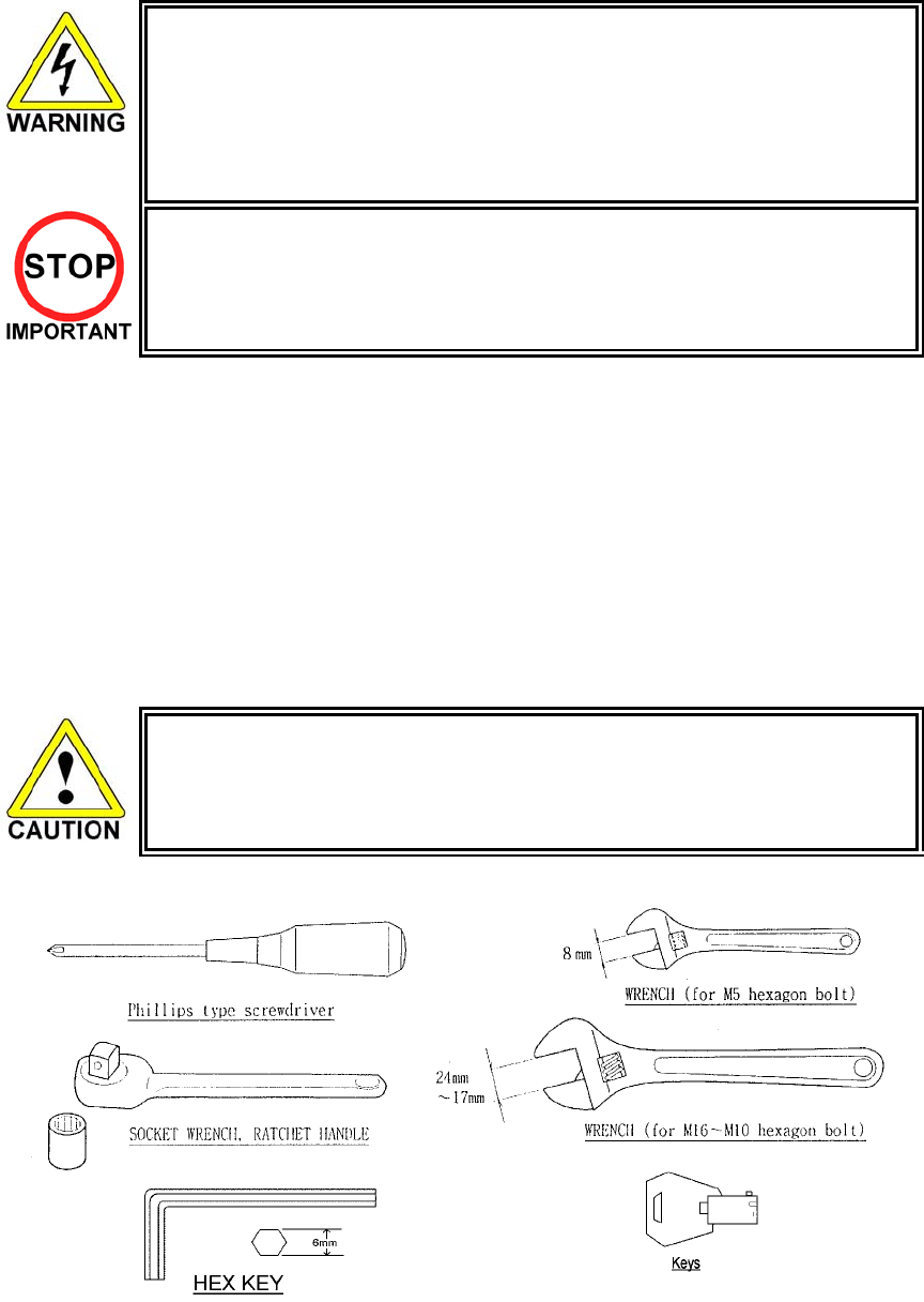
Item 404-406 - Tamper-proof TORX wrench.
14
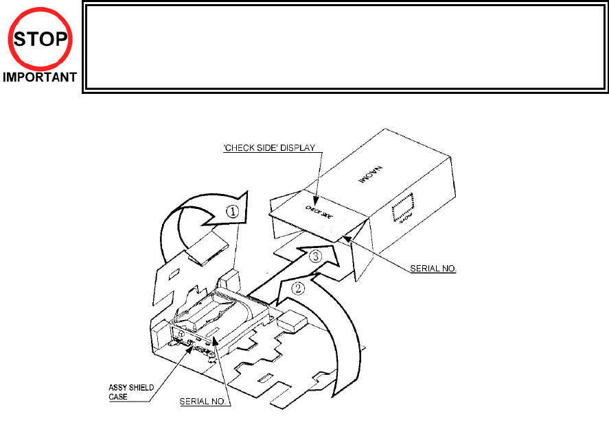
3.5. SHIPPING THE GAME BOARD
• When returning the GAME BOARD for repair or replacement, be sure to package the
entire ASSY SHIELD CASE in the original card transit box - THERE ARE NO USER-
SERVICEABLE PARTS INSIDE.
• Failure to return the GAME BOARD in this manner may invalidate the warranty.
Pack the ASSY SHIELD CASE in the original transit box as shown. Putting it upside down or packing
otherwise in the manner not shown can damage the GAME BOARD and other parts.
15
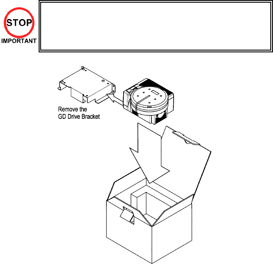
3.6. SHIPPING THE GD-ROM DRIVE
• When returning the GD-ROM DRIVE for repair or replacement, be sure to package it in
the original card transit box - THERE ARE NO USER-SERVICEABLE PARTS INSIDE.
• Ensure the GD-ROM Disk is removed and the GD-ROM Drive Lid is replaced on the
unit, with fixing screw, before packaging. Also, remove the GD-ROM Drive Bracket
and store with the four screws for reuse.
• Failure to return the GD-ROM DRIVE in this manner may invalidate the warranty.
16
3.7. ASSEMBLY INSTRUCTIONS
• Perform the assembly by following the procedure herein stated. Failure to comply
with the instructions, for example, inserting the plug into an outlet at a stage not
mentioned in this manual can cause an electric shock
• Assembling should be performed as per this manual. Since this is a complex
machine, erroneous assembling can cause damage to the machine, or
malfunction to occur.
• Do not attempt to complete this work alone, a minimum of 2 people are required.
• Only QUALIFIED SERVICE PERSONNEL should carry out assembly.
When carrying out the assembly work, follow the procedure in the following 7 item sequence
STEP 1 ASSEMBLING THE COCKPIT
STEP 2 SECURING IN PLACE (LEG ADJUSTER ADJUSTMENT)
STEP 3 BILLBOARD INSTALLATION
STEP 4 INSTALLING THE AC COVERS (WIRE COVERS)
STEP 5 COIN HANDLING INSTALLATION
STEP 6 CONNECTION TO POWER SUPPLY
STEP 7 ASSEMBLY CHECK
Note that the parts contained within the installation kit are required for the assembly work.
• Fit all fixings loosely first as detailed in step 1, then position all components
before finally tightening fixings at step 6.
17
3.7.1. APPLYING THE PLAY INSTRUCTIONS
• Only QUALIFIED SERVICE PERSONNEL should carry out this operation.
Supplied in the installation kit are 4 sets of play instructions in 5 languages. Select the language of
your choice and apply in the following areas:
1. 422-00924UK: Instructions (on Monitor Mask)
2. TOT-0005UK: Card Slot
3. TOS-0004UK: Card Instructions (on Card R/W Lid)
N.B.: Product appearance may differ slightly.
18
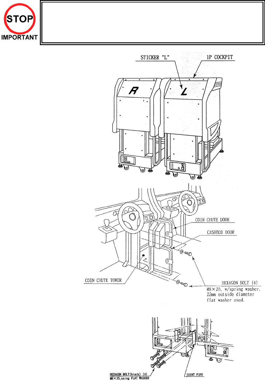
3.7.2. ASSEMBLING THE COCKPIT
• Only QUALIFIED SERVICE PERSONNEL should carry out this operation.
1. Place the two cockpits
side by side. Position the
1P cabinet, which has the
IEC inlet at the left hand
side when viewed facing
the monitor. STICKER L
is attached to the back of
the 1P cabinet and
STICKER R on the back
of the 2P cabinet
2. Install the coin chute
tower in between both
cabinets. Open the coin
chute door and the cash
door and secure with the
4 hexagon bolts from
inside the doors. At this
time, make sure the bolts
are only loosely fitted.
Note: Door may open in opposite way to that shown above
3. Install the joint pipe on
the rear-side of both
cabinets by securing with
4 hexagon bolts, at this
time loosely.
19
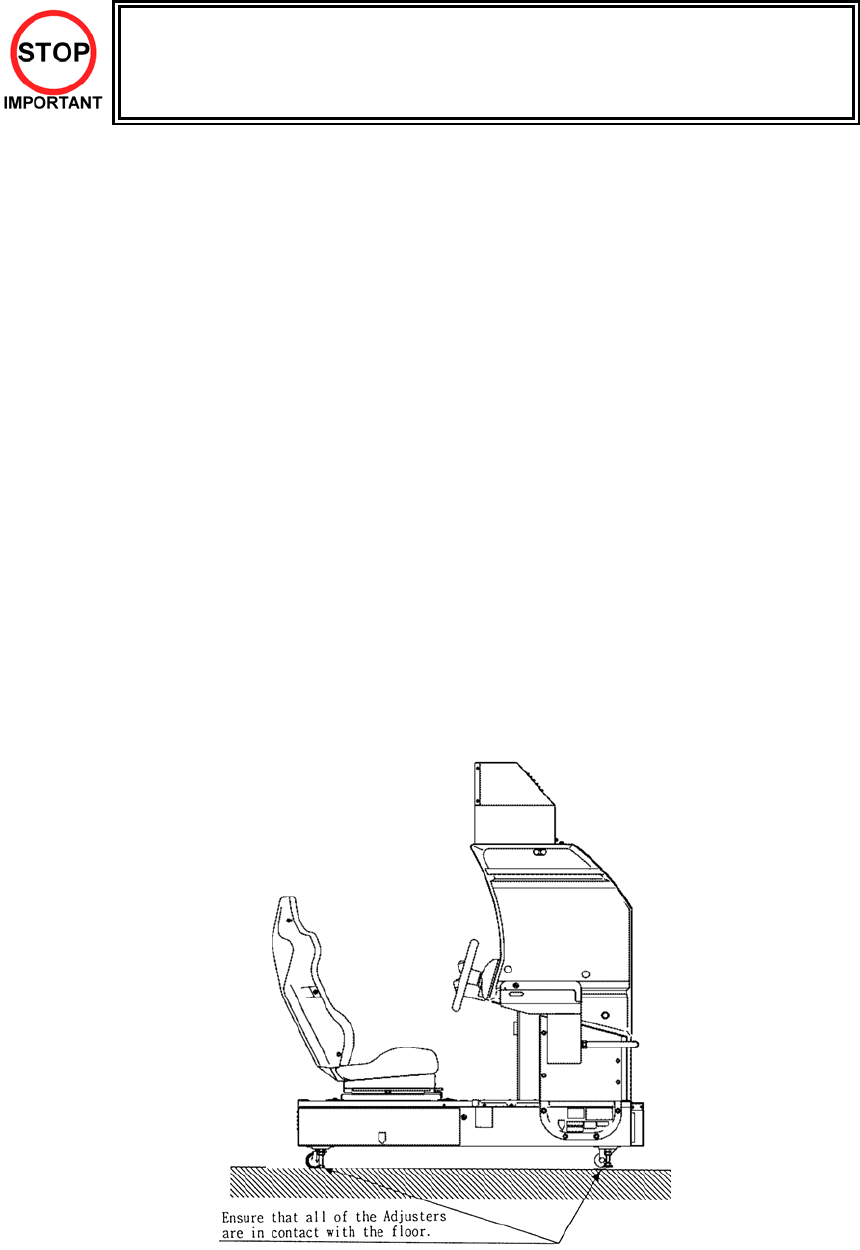
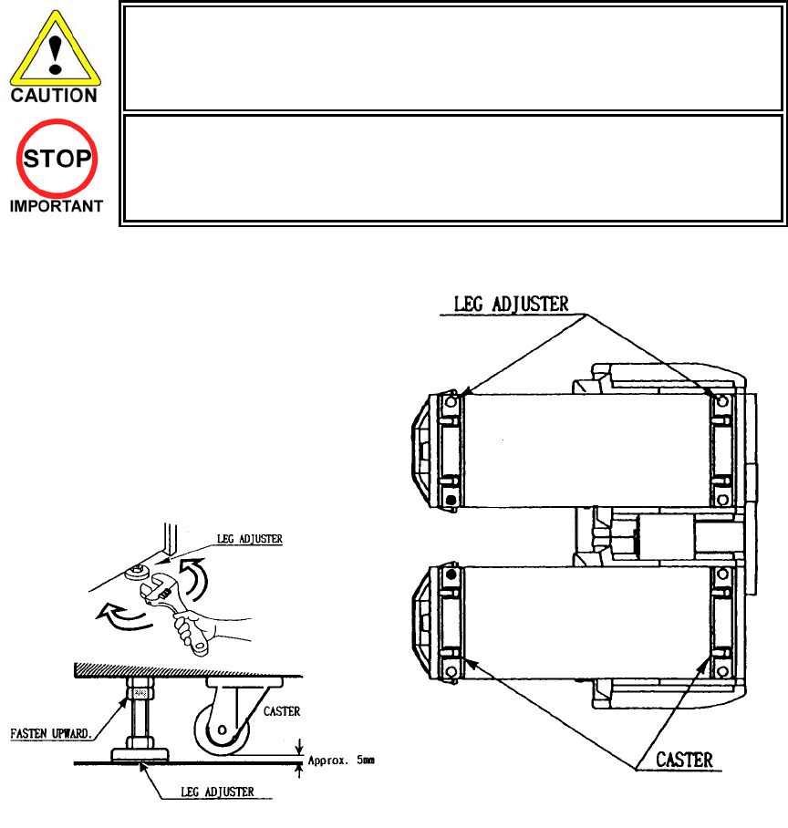
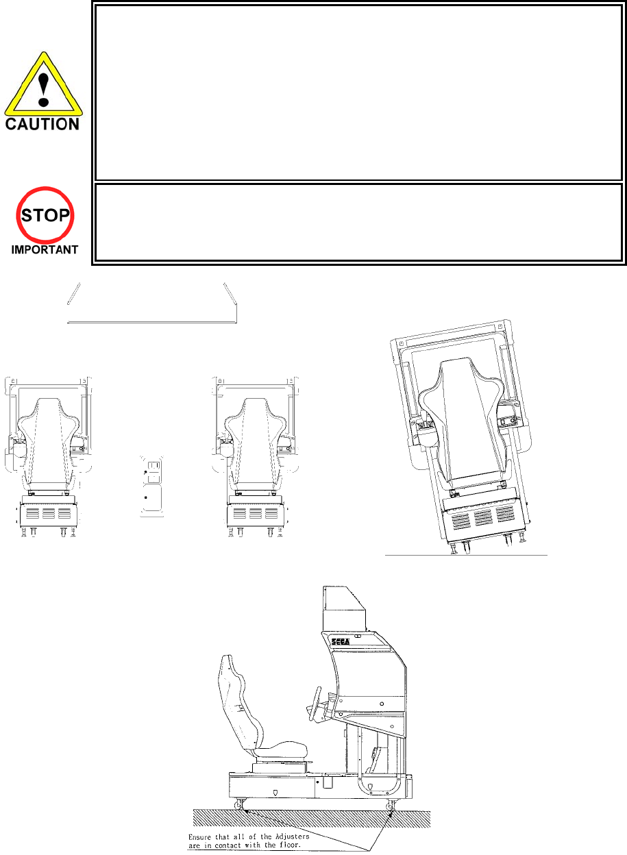
3.7.3. SECURING IN PLACE (LEG ADJUSTER ADJUSTMENT)
• Make sure all of the leg adjusters are in contact with the floor. If they are not the
machines may move and cause injury. This operation requires 2 people.
• Only QUALIFIED SERVICE PERSONNEL should carry out this operation.
This machine has eight castors and eight leg adjusters. When the installation position is decided, unscrew
the leg adjusters so that they raise each caster a minimum of 5mm from the floor. Make sure the machine
is level.
1. Move the machine to the installation position.
When installing against or close to a wall, be
sure to allow an adequate space to allow the
player access to the machine.
2. Make the leg adjusters contact the floor.
Adjust using a spanner as shown below so
that a minimum of 5mm exists between the
casters and the floor. Make additional
adjustment so that the machine is level.
After securing the leg adjuster bolts, fully tighten all bolts temporarily attached in STEP 1 above.
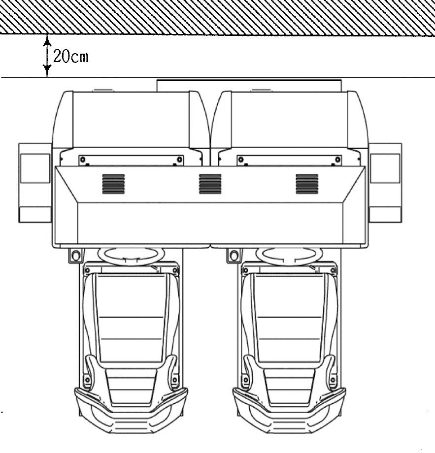
20
Ensure adequate ventilation is maintained as detailed below
21
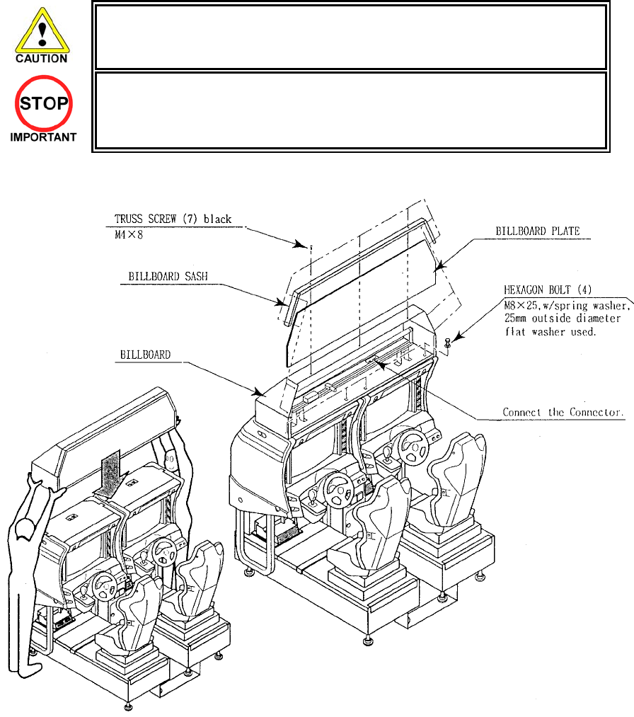
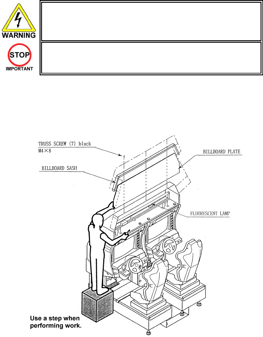
3.7.4. BILLBOARD INSTALLATION
• One person alone cannot perform the installation of the billboard assembly. Seek
assistance before attempting this operation
• Only QUALIFIED SERVICE PERSONNEL should carry out this operation.
1. Install the Billboard over the two cockpits using two or more workers to lift it into position.
2. Remove seven truss screws and take off the Billboard Sash. Withdraw the Billboard Plate.
3. Fasten the four M8x25 hex bolts to secure the Billboard to the cabinets.
4. Connect the wire connectors from the billboard box to the connectors on the cabinet
22
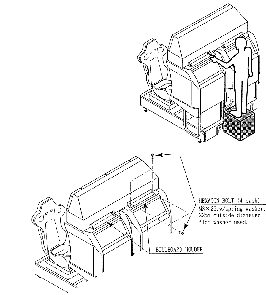
5. Install the two Billboard Holders to the rear of the
Billboard, and secure using four M8x25 hex bolts
for each.
6. Complete installation by reinserting the Billboard
Plate and replacing the Billboard Sash.
23
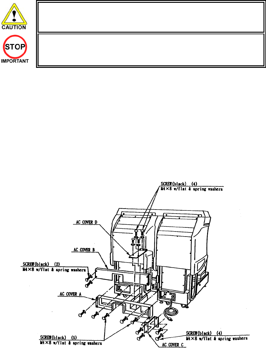
3.7.5. INSTALLING THE AC COVERS (WIRE COVERS )
• Be sure that the machine is not connected to the mains supply before attempting
this operation
• Only QUALIFIED SERVICE PERSONNEL should carry out this operation.
The AC Wire Covers are used for protecting the interconnecting wiring and the fibre optic cables. When
carrying out this operation be very careful so as not to trap any wire between the covers. Pay attention
when handling the fibre optic cables as excessive bending may cause damage.
1. Attach AC Cover A to the rear of the cabinet using 5 screws.
2. Make all the wiring connections between the two cockpits and the Coin Chute Tower. The wiring
connectors are colour coded and cannot be fitted into the wrong size connectors. Do not force any
connectors together.
3. Connect the earth wires between the two AC Brkts, the AC Covers and the Coin Chute Tower.
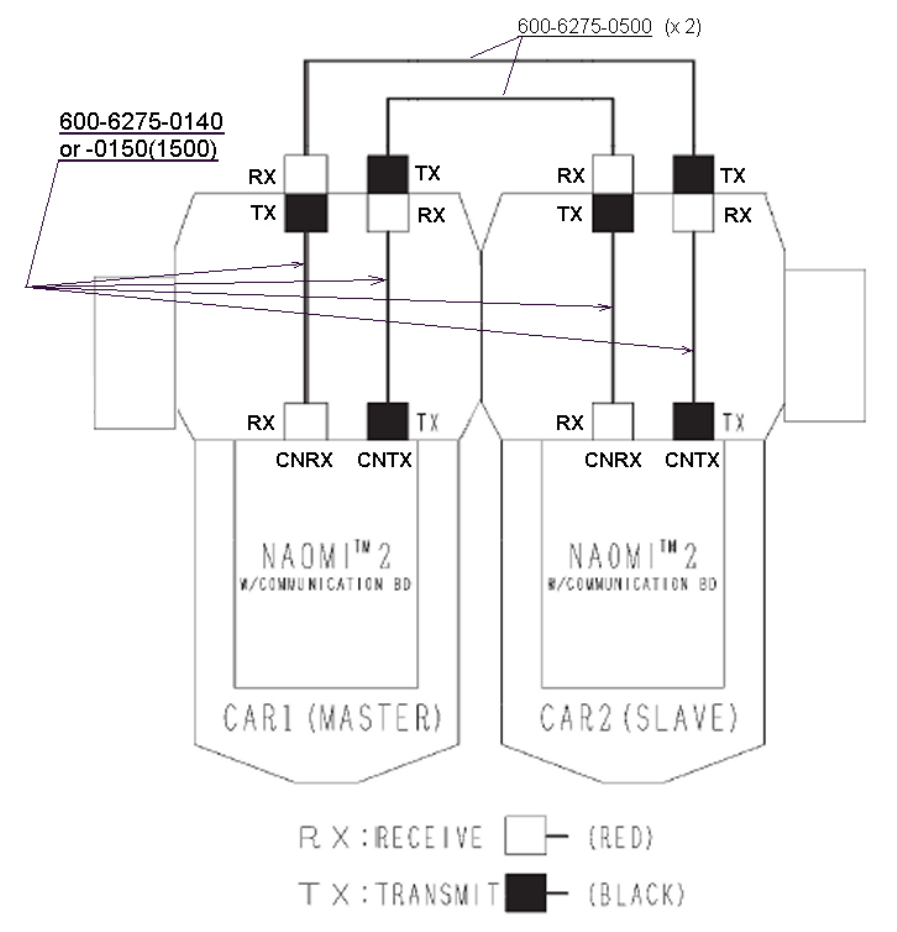
4. Insert the fibre optic cables into the fibre optic connectors. Ensure that the “RX” connection on the 1P
cockpit is connected to the “TX” connector on the 2P cockpit. The other fibre optic connects the “TX”
connector of the 1P cockpit to the “RX” connector of the 2P cockpit.
5. Insert AC Cover B into AC Cover A from above and secure using 2 screws. Be sure not to trap any
cables.
6. Secure AC Cover C and AC Cover D using 4 screws each.
24
3.7.6. COIN HANDLING INSTALLATION
• Only QUALIFIED SERVICE PERSONNEL should carry out this operation.
When fitting the coin mechanism to the door please refer to the specific manufacturers installation
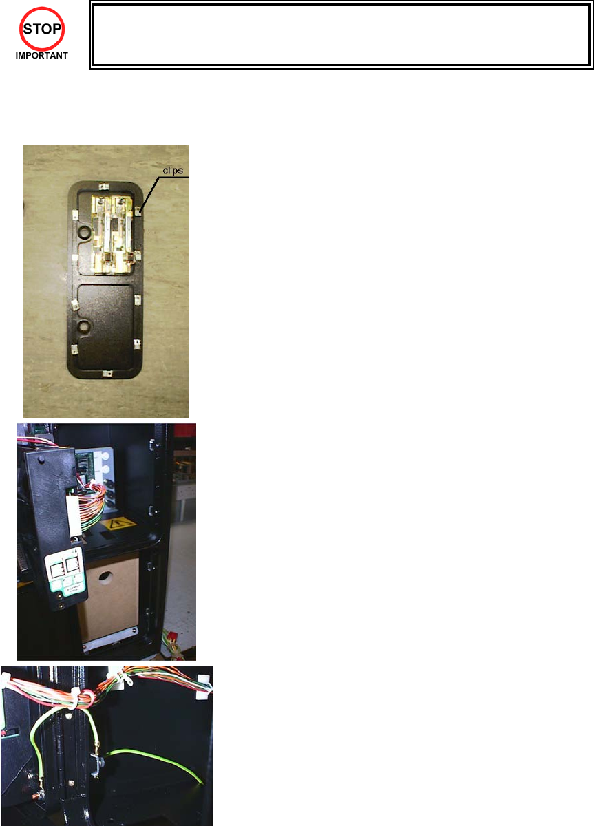
instructions for that coin mechanism. To fit the door to the machine, follow the procedure below.
• Loosen all of the bolts on the frame, which secure the clips.
• Turn all clips in towards the door.
• Position the door into the aperture in the machine.
• Turn the clips around so that they will hold the door in the
machine.
• Tighten all of the bolts.
• Ensure that the door is earthed to the frame and the frame is
earthed to either the VTS bracket or the coin chute tower.
25
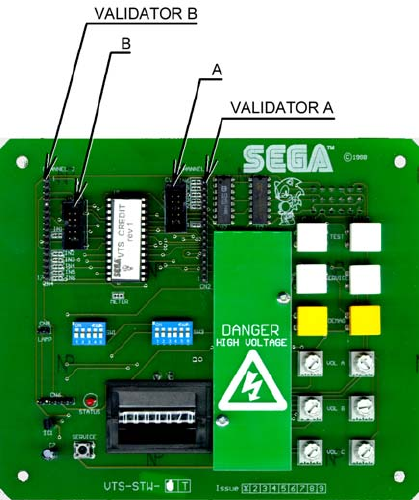
3.7.6.1.WIRING CONNECTIONS.
COIN MECH LOOM INSTALLATION
C220B LM1006IDC
LM1006LAMP-0.1
• Attach the lamp holder to the bracket on the coin return
button.
• Attach one 15-way connector to the C220 coin mech.
• Attach the other 15-way connector to Validator A on the
credit board.
• Attach the 2-way connector to ‘LAMP’ on the VTS
board.
GENERIC
MECHANICALS
LM1008
LM1008-LAMP
• Fit the two lamp holders behind the coin return buttons.
• Attach the blue cable and orange cable to one mech’s
microswitch switch.
• Attach the blue/green cable and orange/green cable to
the other mech’s microswitch.
• Attach the 2-way mate and lok plug to the 2-way mate
and lok cap provided.
• Attach one 15-way connector to Validator A and the
other to Validator B on the credit board
MARS
MS111B1
MARS ME115
LM1007
LM1008-LAMP
• Fit the lamp holder to the bracket behind the coin return
button.
• Fit one of the 13-way connectors to the coin mech.
• Fit the other 13-way connector to Validator A on the
credit board. Note the 13-way connector is keyed and
this key must coincide with the key on the credit board.
SECI, C120,
SR3
OWN LOOM AND
LM1006LAMP-0.1
• Attach the lamp holder to the bracket on the coin return
button.
• Attach the 2- connector to ‘LAMP’ on the VTS board.
• Attach the validator’s own loom to position A on the
credit board
VTS credit board assembly
26
3.7.7. COMMUNICATION CABLES
27
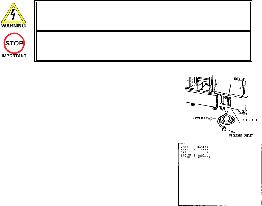
3.7.8. CONNECTION TO THE POWER SUPPLY
• This operation may only be carried out once the machine has been completely
assembled.
• Only QUALIFIED SERVICE PERSONNEL should carry out this operation.
The AC Unit is located on the rear of the 1P cockpit. Using the power
lead supplied connect this to the mains socket at the wall.
1. Turn the mains switch on.
2. Turn the switch on the AC bracket on.
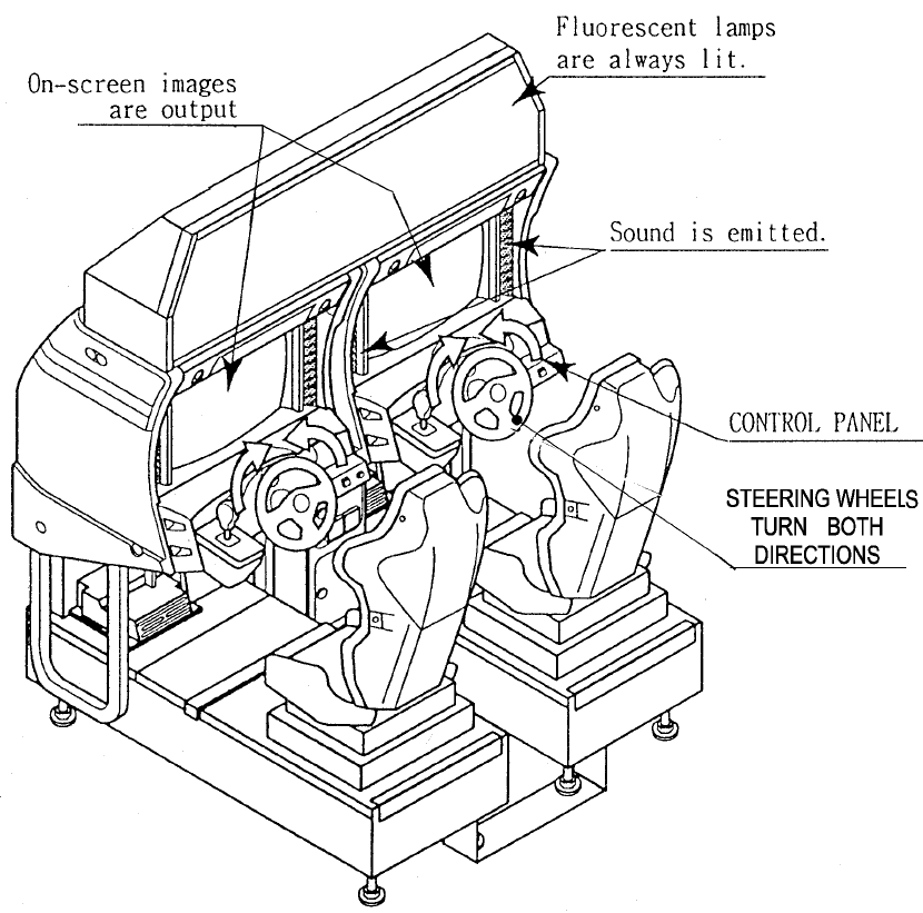
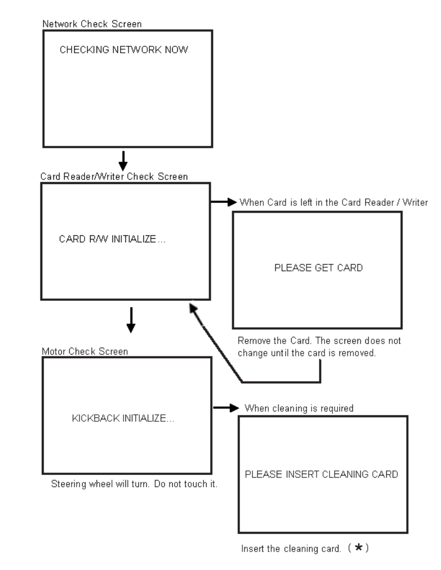
3. Once power is turned on, the fluorescent lamp lights up. The Start
System Screen displays after a lapse of several seconds. This is
followed by the screen that indicates that the network is currently
being checked if the communication mode has been set. If there is
a bad or improper communication connection, each screen will not
proceed to the next, remaining on the currently Network Check
Screen. If this occurs, resolve the error according to the instructions
in this document.
4. If the communication mode has not been set or the communication
check ends normally, the Motor Check Screen returns. While the
Motor Check Screen is on-screen, the steering wheel can move
either clockwise or counter clockwise. If you touch the wheel, the
motor check is hindered and the game will not operate normally.
So, you must not touch it at this time. Failures are displayed, if
found. Resolve the errors according to the instructions in this
document.
5. Once all the above steps have been completed, the Advertise
Screen displays and voices are output through the left and right
loudspeakers, unless you have set the machine so that no voices
are output during the Advertise mode.
6. This product retains the number of credits and the ranking data
even after the power is turned off. It does not retain data about the
fractional number of coins (i.e., the number of coins not reaching
one credit) or the bonus adder count.
28
29
Each Check Screen is followed as below:
Sec HEAD CLEANING, Section 3.9.2.2
30
3.7.9. ASSEMBLY CHECK
• Only QUALIFIED SERVICE PERSONNEL should carry out this operation.
In the TEST mode ensure the assembly has been made correctly by performing the following checks.
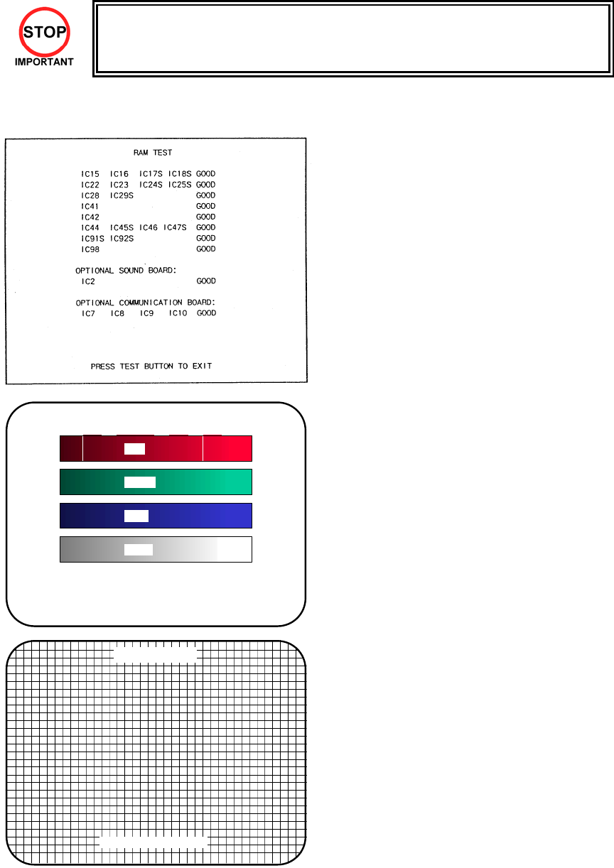
Selecting the RAM test on the test mode menu
causes the on -board memory to be tested. The
game board is satisfactory if the display beside each
IC No. shows GOOD
C.R.T TEST
PAGE 1/2
C.R.T. TEST 1/2
PRESS TEST BUTTON TO CONTINUE
RED
GREEN
BLUE
WHITE
In the TEST mode select CRT test to check the
screen is satisfactory.
Although the projector has been set up before
shipment at the factory check to see if the screen
needs adjustment.
C.R.T. TEST 2/2
PRESS TEST BUTTON TO EXIT
31
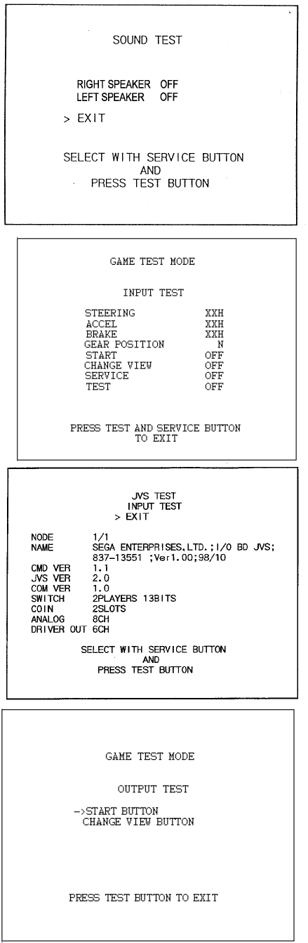
Select SOUND test-to-test sound BD and wiring
connections. Check that the sound is satisfactory
from each speaker and the speaker volume is
appropriate.
INPUT TEST tests the input devices. Using this
screen, check the input devices periodically.
Operate each input device. If the display at the right
of the appropriate device changes from OFF to ON,
it is diagnosed as being normal.
Check that each of the indications at the right of
STEERING, ACCEL, BRAKE and GEAR
POSITION change smoothly in response to
operations of each of the input devices.
Pressing the TEST button returns you to the Game
Test Menu Screen.
For the coin switch test, insert a coin into the inlet
while the cash door is open.
If the display beside each item shows ON as the
input is made, the switches and wiring connections
are satisfactory.
• Pressing the SERVICE button moves the
arrow. With the arrow aligned with the tested
lamp item, press the TEST button.
• If the lamp lights up when the indication at the
right of each name is ON and goes out when it
is OFF, this lamp and wiring connections are
normal.
• By selecting EXIT and pressing the TEST
button, you return to the Game Test Menu
Screen.
32
3.7.10.MOVING THE MACHINE
• When moving the machine, be sure to remove the plug from the power supply. Moving
the machine with the plug inserted can cause the power cord to be damaged, resulting
in a fire or electric shock.
• When moving the machine, retract the leg adjusters fully and ensure the casters make
contact with the floor. During movement pay careful attention so that the casters or leg
adjusters do not damage any other cabling laid on the floor. Such damage could result
in a fire or electric shock.
• Don’t push the cockpit cabinets from the side, as they may topple and cause damage.
• Don’t put excessive pressure on the glass or plastic components as damage or
personal injury may result if there is a breakage.
• Only QUALIFIED SERVICE PERSONNEL should carry out this operation.
Disassemble the cabinet into its components if
transporting up or down step level changes!
Do not push an individual cockpit from the side!
33
3.8. FUSES
• Never touch places other than those specified. Touching places other than those
specified can cause electric shock and short circuit. Disconnect the machine from
the supply before attempting the replacement of any fuse.
• Only QUALIFIED SERVICE PERSONNEL should replace FUSES.
There are a number of fuses used on this machine to protect the user and the machine from damage. Only
replace the fuse once you have remove the cause of its failure. Detailed below is a list of the fuses used,
their location and if relevant PCB reference:
PART NUMBER LOCATION TYPE & DETAILS QTY PER
COCKPIT
514-5078-6300 838-11856CE (F1) 5x20 HRC SB 6300mA 1
514-5078-10000 EP1302 (IEC INLET) 5x20 HRC SB 10000mA 1 (PER MACHINE)
514-5078-4000 400-5397-01 (F1) 5x20 HRC SB 4000mA 1
514-5078-6300 838-13578 5X20 CERAMIC SB 6300MA 1
514-5080-15000 838-14174 (F1) 32x6.35 HRC SB 15000mA 1
514-5078-2500 838-14174 (F2) 5x20 HRC SB 2500mA 1
514-5033-5000 400-5421-07512 (F11) 5x20 Glass T 125v 5 A 1
514-5078-5000 AC BRACKET 5x20 HRC SB 5000mA 1
There are also fuses located on the Monitor PCB. Refer to the relevant Monitor manual supplied to
reference these fuses.
34
3.9. MAINTENANCE
• Only Qualified Service Personnel must carry out maintenance.
• Ensure that the mains power is switch OFF and disconnected before attempting
any work.
• The CONTROL PANEL ASSEMBLY is heavy and may cause injury or damage
to the machine if dropped. Use an assistant when removing and replacing it.
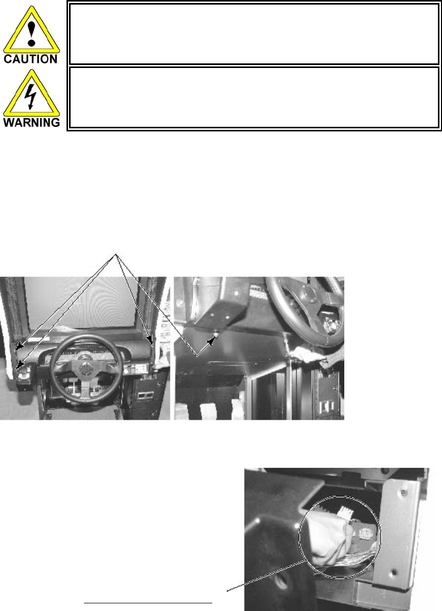
3.9.1. HANDLE MECHA
The handle mecha unit is housed in the control panel assembly. Follow the procedure below to access the
components.
REMOVAL
• Turn the POWER switch OFF
• Remove a total of six M8 tamperproof bolts from both sides of the Control Panel. Have your
assistant support the Control Panel’s weight while you remove the bolts.
6 x M8 BOLTS
• Wiring connectors are connected inside the Control Panel. Carefully withdraw the control panel in
a manner so as not to damage the wiring.
• Disconnect the wiring connectors
DISCONNECT CONNECTOR
35
3.9.1.1.REPLACING AND ADJUSTING THE HANDLE MECHA’S
VR
• Never touch places other than those specified. Touching places other than
those specified can cause electric shock and short circuit.
• After the replacement or adjustment of the V.R. be sure to set the Centre of
Steer in the DRIVE BOARD TEST.
In the TEST MODE, if the steering wheel VR variations are not within the allowable limit, the VR installation
position may require adjustment or replacement. Also be sure to apply grease every 3 months.
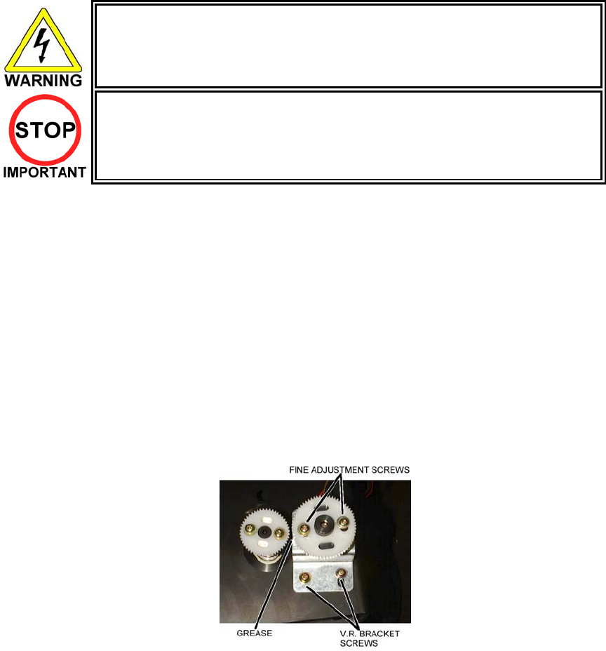
3.9.1.1.1.ADJUSTING THE VR
Remove the CONTROL PANEL as detailed above. Locate the V.R. on the rear surface of the HANDLE
MECHA.
• By using a screwdriver loosen the 2 machine screws that secure the V.R. Bracket. Move the V.R.
Bracket so as to disengage the gears.
• Gently rotate the VR until its value is within the range of the centring position.
• Mesh the gears together. Make sure that a correct amount of backlash is maintained.
• If the VR value is still not correct make fine adjustments by loosening the 2 machine screws on the VR
gear. Rotate the gear holder until the correct value is obtained.
• The value should be adjusted such that with the steering wheel in the centre position the value read
during INPUT TEST shall be 2000H±5H.
3.9.1.1.2.REPLACING THE VR
• Remove the CONTROL PANEL as detailed above. Locate the VR on the rear surface of the HANDLE
MECHA
• By using a screwdriver remove the 2 machine screws that secure the VR Bracket. Remove the VR
Bracket so as to disengage the gears.
• Loosen the hexagon drive grub screws in the collar and gently slide off the VR
• Reassemble is the reverse procedure of steps 1 and 2 above.
• When complete you must readjust the VR in accordance with the paragraph above.
36
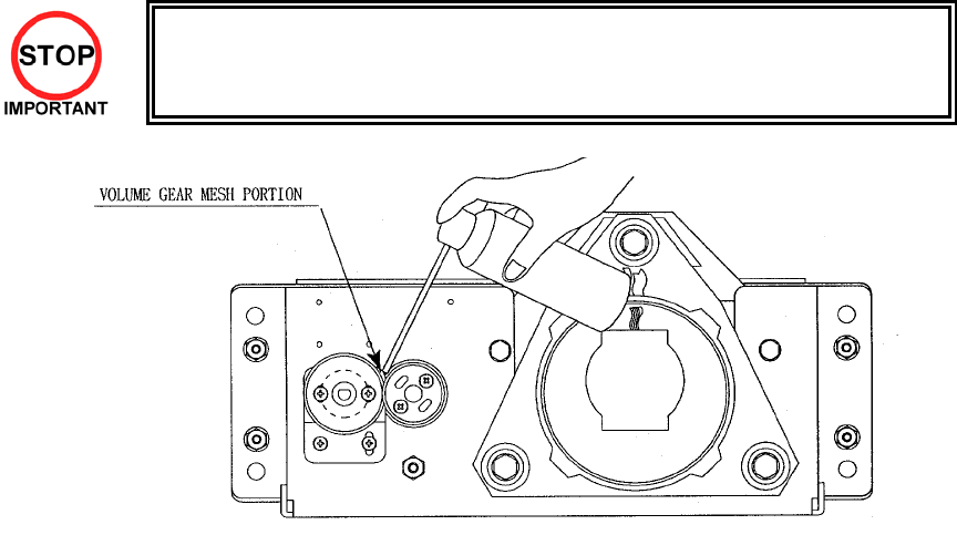
3.9.1.2.GREASING
• Ensure proprietary SYNTHETIC grease is used. Different types of mineral-
based grease may damage plastic parts.
• Apply grease only to specified locations.
Apply grease to meshing portion of gears once every THREE months. Use proprietary synthetic grease.
37
3.9.2. CARD READER/WRITER UNIT
• Take care to work on the machine with the power turned off. In the powered
state, the machine may operate suddenly and can cause fingers to be
pinched or cut.
3.9.2.1.SETTING DEDICATED CARDS
• Be sure to use dedicated cards available for this product. Use of ones other
than such dedicated cards may cause a malfunction or failure of the machine.
• Be sure to set the specified number of card in the specified orientation by
using the specified procedure. Wrong setting of the cards may cause the
machine to fail.
• This machine allows you to set up to 100 cards at a time. You must not set
over 101 cards at a time. If you do so, a trouble such as card jamming may
occur.
• Set virgin cards taken out from a container that was unpacked immediately
before use.
• Use of any deformed or deteriorated card may cause a trouble.
• Do not include a corrugated, bent, or used card in the card deck.
When the unit is out of cards, a message will be displayed at the upper right of the screen during
advertisements. Follow the instructions below to restock the system with cards. Cards may be stocked
when the unit is on or off.
After restocking the system with cards, the message displayed after the "SEGA" logo will be updated.
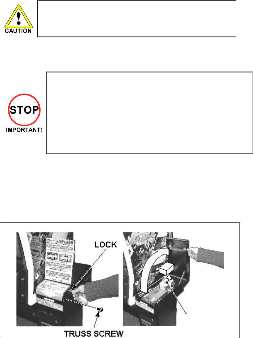
Gameplay can be resumed without waiting for the updated message.
Remove the truss screw
A) Unlock and open the cover to find the card reader/writer.
The dispenser on which you should place the cards is located at the rear of the reader/writer.
B) From the card reader/writer, take out the dispenser upward in a straight line.
38
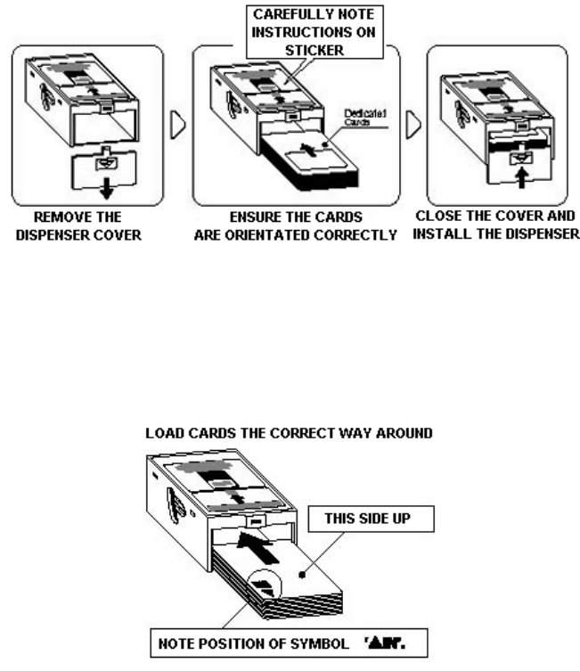
C) Remove the cover from the back of the dispenser.
D) Place the cards into the dispenser according to the instructions on the sticker attached to the dispenser.
Refer to the diagram shown on the sticker and insert the cards. Be careful not to insert the cards in the
wrong direction or with the wrong side facing up.
The Dispenser can only hold 100 cards. Do not attempt to insert more than 100 cards, as too many
cards may cause the Dispenser to jam or result in other problems.
Insert magnetic cards into the Dispenser in complete packs of 100 or after carefully counting the
number of cards (not to exceed 100).
E) Reinstall the cover to the dispenser.
F) Insert the dispenser into the card reader/writer. The dispenser can be inserted only in the
predetermined orientation.
G) Close and lock the cover.
H) Secure with the truss screw
39
3.9.2.2.HEAD CLEANING
• The unit enters Head Cleaning Mode when any of the following conditions are
met:
• At power-up if the Card Reader/Writer has operated 100 times or more
• At power-up if the date has been updated
• At boot time after performing Backup Data Clear
• Once the unit enters Head Cleaning Mode, follow the on-screen instructions and
perform Head Cleaning. The unit will not exit Cleaning Mode (i.e. games may not
be played) until head cleaning is complete.
• Always use the designated Cleaning Card. Using anything other than the
designated card or carrying out any other procedure other than the one outlined in
the manual may cause faulty printing, faulty operation and/or unit failure.
• Cleaning Cards may only be used once. Dispose of them after use.
• Cleaning Cards should be used immediately after removal from the package.
Cleaning Cards will not clean effectively if dried out.
• Perform head cleaning only when there are cards in the Card Reader/Writer
Dispenser. If the Dispenser is empty, the part that secures the cards inside the
Dispenser may touch the rotating part of the Card Reader/Writer and cause noise.
• Always remember to remove the Cleaning Card after completing head cleaning.
• After head cleaning, wait for the "SEGA LOGO" to be displayed at least twice
before resuming gameplay.
This machine records the number of times the Card Reader/Writer is used.
The Card Reader/Writer writes data to and reads data from cards. Each write and read is counted, so the
Card Reader/Writer usage count will not be the same as the number of times the game is played.
Once head cleaning of the Card Reader/Writer is complete, the unit will exit this mode.
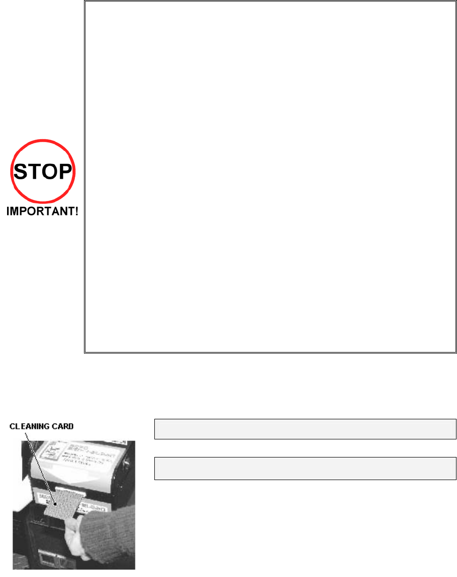
Follow the on-screen instructions to carry out cleaning.
PLEASE INSERT CLEANING CARD
Insert the Cleaning Card into the card slot.
NOW CLEANING...
Indicates that the unit is undergoing cleaning. Wait for cleaning to be
completed.
The unit exits to normal mode after cleaning is complete.
Do not forget to remove the Cleaning Card.
Wait for the "SEGA LOGO" to be displayed at least twice before
resuming gameplay after cleaning.
The Card Reader/Writer usage count described above is reset when cleaning is performed.
Manual head cleaning may also be performed from Test Mode. Refer to Test Mode Section 5.3.8for more
details.
40
3.9.2.3.CLEARING CARD JAMS
When attempting to perform this operation without powering down so that
gameplay can be restored, exercise extreme caution. Machine parts may move
unexpectedly when the power is ON. This may result in fingers being caught or
severed and other injuries.
Verify the Stay Lock on the top cover before attempting this procedure. If the top
cover closes during the procedure, it may result in serious injury.
If a problem, such as card jamming, occurs on the card reader/writer it will be reported on the screen. Play
cannot proceed unless this problem is resolved. Identify the nature of the problem before any action is
taken.
If repeated attempts continue to generate errors, follow the instructions below to remove the card.
Removing the card may force the game to shut down. If the game shuts down, existing customer game
data will not be saved.
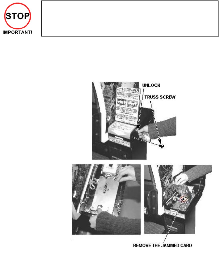
A) Remove the truss screw.
B) Unlock and open the cover.
C) Unlock the hatch by drawing the green
shaft attached to the top cover on the
card reader/writer. While drawing the
shaft, open the cover up.
D) Remove the card jammed in the card
reader/writer.
E) While drawing the shaft,
close the cover. With the top
cover closed, release the
green shaft. Check that the
top cover has been locked
securely.
E) Close and lock the cover.
F) Secure with the truss screw.
41
3.9.3. ACCELERATOR & BRAKE
• Only Qualified Service Personnel must carry out maintenance. Ensure that the
mains power is switched OFF and disconnected before attempting any work.
In the TEST MODE, if the brake or accelerator V.R. variations are not within the allowable limit, the V.R.
installation position requires adjustment or the V.R. needs replacement. Also be sure to apply grease to all
moving parts every 3 months.
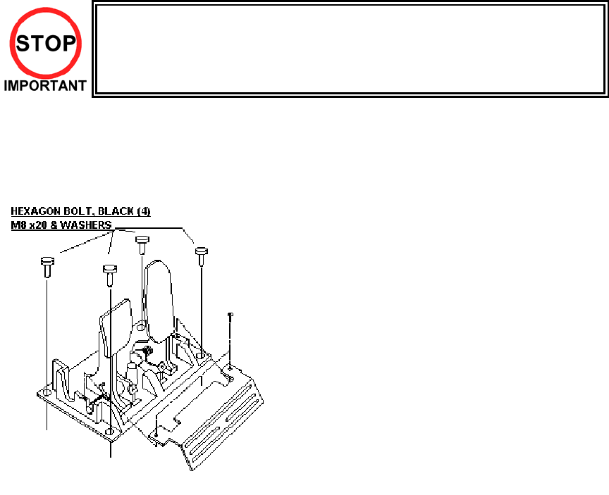
3.9.3.1.Removing the Accelerator & Brake.
1. Turn the POWER switch OFF
2. Remove a total of 4 screws securing the
covers over the ACCELERATOR & BRAKE
3. Fine adjustment of the V.R. values is
accomplished with just these covers
removed.
4. Coarse adjustment requires the
ACCELERATOR & BRAKE mounting bolts to
be removed. If this is necessary, remove the
bolts from the unit, but do not remove the unit
from the machine. Take extreme care when
operating the unit in this condition as damage
to other components can occur.
42
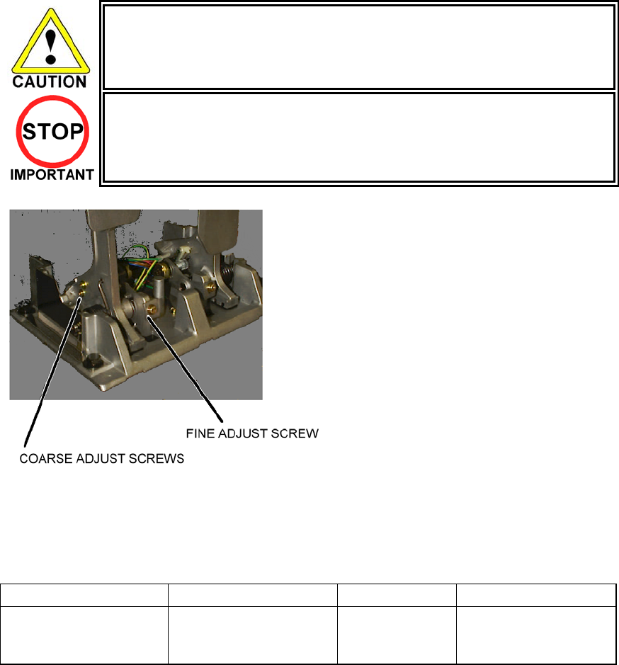
3.9.3.2.Adjusting the V.R.
• Never touch places other than those specified. Touching places other than
those specified can cause electric shock and short circuit.
• After the replacement or adjustment of the V.R. be sure to set the values in the
INPUT TEST.
1. Remove the cover panels as detailed above.
2. Fine Adjustment - By using a screwdriver loosen
the 2 machine screws that secure the V.R. arm.
Move the V.R. arm to adjust the V.R. value
within the relaxed range.
3. Coarse Adjustment - Remove the four hexagon
bolts detailed above and remove the side
covers of the Accelerator & Brake.
4. Loosen the two machine screws holding the
V.R. rack
5. Move the V.R. rack away so as to disengage
the V.R.
6. Gently rotate the V.R. until its value is within the
range of the centring position.
7. Mesh the gears together. Make sure that a
correct amount of backlash is maintained.
8. If the V.R. value is still not correct make fine
adjustments as detailed above.
The required values are:
GAS PEDAL: Under 30H ⇒ Over C0H
BRAKE PEDAL: Under 30H
(THE PEDAL
RELEASED)
⇒ Over C0H
(THE PEDAL
PRESSED)
43
3.9.3.3.Replacing the V.R.
1. Loosen and withdraw the V.R. rack as detailed above.
2. Using a hexagon key loosen the two grub screws holding the V.R. gear onto the V.R.
3. Remove the V.R. gear
4. Using a spanner remove the nut holding the V.R. in position.
5. Gently remove the V.R. and its wire harness.
6. Refit is the reverse of removal.
7. When complete you must readjust the V.R. in accordance with the paragraph above.
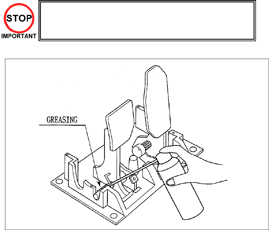
3.9.3.4.Greasing
• Be sure to use a good quality, synthetic lubricant. Using a mineral-based
lubricant will cause damage to the plastic parts.
• Do not apply lubricant to parts other than those specified. Doing so may cause
damage or deterioration of parts.
Apply lubricant to gear mesh portions once every 3 months.
44
3.9.4. SHIFT LEVER
In the Test Mode, if the SHIFT LEVER's SW can not be inputted satisfactorily, replace the Switch. Apply
greasing to the Mechanism's sliding portion once every 3 months.
When performing the above work, remove the Shift Lever Unit.
• Before starting to work, ensure that the Power SW is OFF. Failure to
observe this can cause electric shock and short circuit hazards.
• Use care so as not to damage wirings. Damaged wiring can cause
electric shock and short circuit hazards.
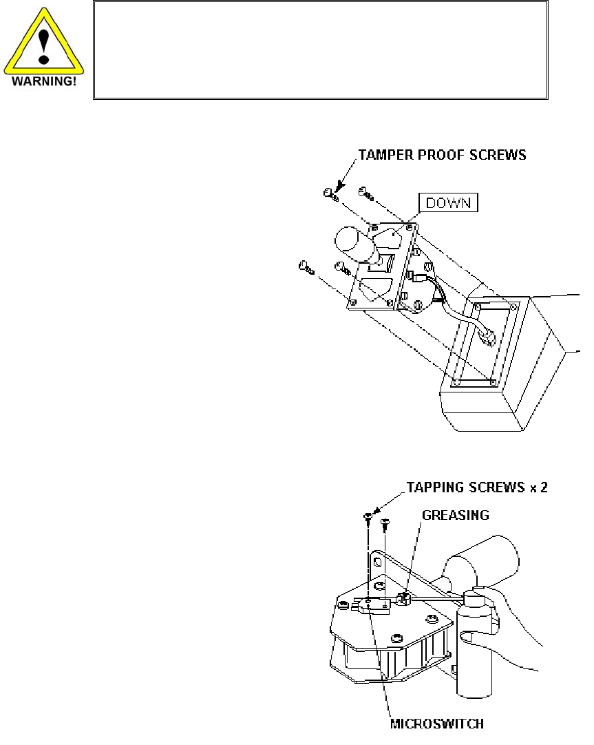
REMOVING THE SHIFT LEVER
A) Turn the Power SW off.
B) Remove the 4 Tamperproof Screws to lift
the Shift Lever Unit.
C) Disconnect the Connector to remove the
Shift Lever Unit.
D) When reinstalling, follow the procedure
opposite as when removing. At this time,
ensure that "DOWN" display appears on
the upper part as shown.
E) After reinstalling, be sure to check INPUT
TEST in the test mode. (TEST.)
SWITCH REPLACEMENT
A) Disconnect the wiring Connector of the
Switch to be replaced.
B) Remove the 2 Tapping Screws to replace
the Microswitch.
GREASING
Apply greasing once in 3 months to the specified
portions.
For spray grease, use NOK KLUBER L 60 or
Grease Mate (Part No. 090-0066).
45
3.10. REPLACEMENT OF FLUORESCENT LAMP AND OTHER LAMPS
• Never touch places other than those specified. Touching places other than those
specified can cause electric shock and short circuit. Disconnect the machine from
the supply before attempting the replacement of any lamp.
• Prepare a secure step when working on the upper parts of the machine.
• Only QUALIFIED SERVICE PERSONNEL should replace lamps.
3.10.1.FLUORESCENT LAMP REPLACEMENT
1. Turn the POWER switch OFF.
2. Remove the POP if fitted, and remove the Billboard Sash by taking out the three screws, and withdrawn
the Billboard Plate.
3. Remove the end caps from the fluorescent tube.
4. Carefully pull the tube out of the clips with a twisting action.
46
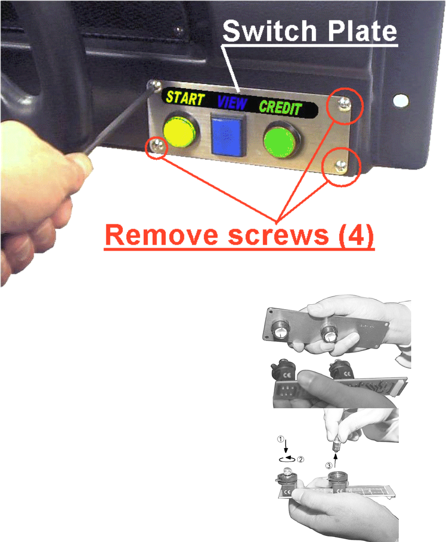
3.10.2.START BUTTON LAMP REPLACEMENT
1. Turn off power.
2. Take out four screws to remove the ASSY START SW from the CONTROL PANEL. Withdraw the
ASSY START SW far enough only to disconnect the block connector of the START button.
3. The lamp (bulb) is on the inner side of the
assembly. Turn the metal locking tag
anticlockwise (when viewing the rear of the
button) on each button, and remove the lamp
housings from the assembly.
4. To remove the lamp, press it down and turn
anticlockwise.
47
3.10.3.CLEANING THE CABINET SURFACES
When the cabinet surfaces are badly soiled, remove stains with a soft cloth dipped in water or diluted
(with water) chemical detergent and squeezed dry. To avoid damaging surface finish, do not use such
solvents as thinner, benzine, etc. other than ethyl alcohol, or abrasives, bleaching agent and chemical
dustcloth.
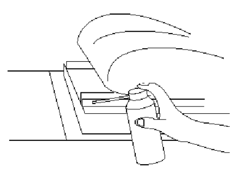
3.10.4.SEAT (Greasing to Seat Rail Portion)
Move the Seat to the rearmost position
and apply spray greasing to the portion
shown at the right once every 3 months by
using NOK KLUBER L60 or GREASE
MATE SEGA PART No. 090-0066.
After greasing, move the Seat a few times
forward and backward so as to allow the
grease to be applied all over uniformly. Be
sure to wipe grease which attaches to the
surfaces of the PROTECT RUBBER on
the Seat Rail, or any excess grease.
48
3.11. TROUBLESHOOTING
• Only QUALIFIED SERVICE PERSONNEL should carry out these procedures.
3.11.1.CARD READER/WRITER
If this machine detects an error during the operation of the Card Reader/Writer, it will display the error
messages listed below. Perform the appropriate maintenance based on the content of the error message
displayed.
Should an error occur, do not attempt to open the top cover of the Card Reader/Writer. The unit will attempt
to save the data to the customer's card and restore the game if the top cover is closed and the RESTORE
command (hold down the Start button + Change View button for a short time) is used. However, attempting
to use the RESTORE command after the top cover has been opened may force the game to shut down and
not save data to the card.
When the game shuts down or the unit is reset, the data on the customer's card is not saved. In order to
save customer data, perform the proper maintenance carefully.
ERROR DISPLAY CAUSE COUNTERMEASURES
Error occurred while reading
card. Card will be ejected
without saving data. Please
press the Start and Change
View buttons.
This message is displayed after
several failed attempts to save data to
the card at the end of the game.
Press the Start button and Change View button
at the same time to eject the card and end the
game.
Error occurred while saving
data. Please notify a store
attendant. Please press the
Start and Change View
buttons.
This message is displayed after
several failed attempts to print at the
end of the game.
Leave the card in place and press the Start
button and Change View button at the same
time to retry the save operation.
Remove the card and press the Start button
and Change View button at the same time to
restore or end the game.
If this error occurs several times, use Test
Mode to perform manual cleaning. (See
Cleaning Section 5.3.8)
Printing error. Card will be
ejected without printing or
saving data. Please press
the Start and Change View
buttons.
This message is displayed after
several failed attempts to read the
card at the end of the game.
Press the Start button and Change View button
at the same time to eject the card and end the
game.
A shutter error has occurred.
Please remove any cards
present in card insertion slot.
Please press the Start and
Change View buttons.
This message is displayed when the
shutter is forced open or if the unit
detects a problem with the shutter.
This message is displayed when the
unit is unable to open/close the
shutter.
Correct the problem, then press the Start
button and Change View button at the same
time to restore the game. Circumstance may
force the game to shut down.
Correct the problem, then press the Start
button and Change View button at the same
time to restore the game.
This card cannot be used.
Card will be ejected without
saving data. Please press
the Start and Change View
buttons.
This message is displayed when the
card in the Card Reader/Writer is not
a proper player card at the end of the
game.
Press the Start button and Change View button
at the same time to eject the card and end the
game.
Card jam. Ejecting card.
Please press the Start and
Change View buttons.
This message is displayed when
various operations fail because of
dirty rollers or heads.
Press the Start button and Change View button
at the same time to eject the card and restore
the game.
If this error occurs several times, use Test
Mode to perform manual cleaning. (See
Section 5.3.8)

49
Continued from previous page
ERROR DISPLAY CAUSE COUNTERMEASURES
There is a problem with the
card reader/writer. Please
notify a store attendant.
Please turn off the power
and start again.
This message is displayed when there
is a problem with the Card
Reader/Writer and it sends improper
signals.
Verify there are no problems with the
shutter and that the top cover is closed
and then restart the unit. (See 3.9.2)
The card reader/writer is not
responding. Please notify a
store attendant. Check the
card reader/writer is
connected properly, turn off
the power and start again.
This message is displayed at power-
up during advertisements when the
Card Reader/Writer is not connected
properly or when it is broken and
unresponsive.
Verify that the Card Reader/Writer is
connected properly and then restart the
unit. (See Schematic Section 9.2)
SCIF Error. Please notify a
store attendant. Check that
the card reader/writer is
connected properly, turn off
the power and start again.
This message is displayed when a
communication error occurs between
the Card Reader/Writer and the game
board.
Verify that the Card Reader/Writer is
connected properly and then restart the
unit. (See Schematic Section 9.2)
If this error occurs several times, check
the immediate area for sources of
possible interference.
This message is displayed when
various operations fail because of
dirty rollers or heads.
Leave the card in place and press the
Start button and Change View button to
retry the operation.
Remove the card and press the Start
button and Change View button at the
same time to restore or end the game
(refer to 3.9.2).
If this error occurs several times, use
Test Mode to perform manual cleaning.
(See Section 5.3.8)
Card jam. Remove the card
and press the Start and
Change View buttons. If the
card cannot be removed,
please notify a store
attendant.
This message is displayed when a
card jam is suspected when there
should be no card in the Card.
Press the Start button and Change View
button at the same time after removing
the card or correcting the problem to
restore the game. (See 3.9.2)
50
The following error messages are displayed when problems are detected during unit power-up (during
initialization of the Card Reader/Writer). Perform the appropriate maintenance based on the content of the
error message displayed.
ERROR DISPLAY CAUSE COUNTER MEASURES
CARD R/W ERROR! This message is displayed at
power-up when the Card
Reader/Writer is not
connected properly or when
it is broken and
unresponsive.
Verify that the Card Reader/Writer is
connected properly and then restart
the unit. (See Schematic Section 9.2).
If broken, contact the company from
whom the unit was purchased.
PLEASE INSERT CLEANING CARD. This message is displayed
when the conditions
prompting an automatic Card
Reader/Writer cleaning are
met.
Perform the Card Reader/Writer
cleaning. (See Section 3.9.2.2)
PLEASE WAIT This message is displayed
during network setup while
the other unit is being
initialized.
This message disappears once
initialization of the other network game
unit is complete.
This message is displayed at
power-up when, after
attempting to do so, the Card
Reader/Writer is unable to
eject a card for some reason.
Remove all cards from the Card
Reader/Writer. (See 3.9.2.)
CAN'T EJECT
This message is displayed at
power-up when the shutter
cannot be opened/closed
properly.
Verify that there are no problems with
the shutter and then restart the unit. If
this error occurs several times,
contact the company from whom the
unit was purchased.
The following messages are displayed when there are limits to the Card Reader/Writer Operation Mode.
The messages are displayed in the upper right of the screen during advertisements. The message content
is updated after the "SEGA LOGO" is displayed.
If the message is not one displayed intentionally by the Operation Mode, perform the appropriate
maintenance based on the content of the error message displayed.
ERROR DISPLAY CAUSE COUNTER MEASURES
The machine is currently
unable to issue new cards.
Please see a store attendant to
have the machine restocked
with cards.
The Card Reader/Writer
Dispenser is empty (no cards).
Restock the Dispenser with cards.
(See 3.9.2)
If no cards are available, contact the
company from whom the unit was
purchased
Cards may not be used at this
time.
Cards may not be used due to
the Store Closing setting being
activated.
If there is a mistake in the settings,
use Test Mode to change the Store
Closing setting. (See Section 5.3.9)
(See Schematic, Section 9.2)
If the setting is correct, but not
operating properly, check the internal
clock settings on the game board
(Refer to the Service Manual.)
51
3.11.2.TROUBLESHOOTING (WHEN NO ERROR MESSAGE IS SHOWN)
• In order to prevent electric shock and short circuit, be sure to turn power off before
performing work.
• Be careful so as not to damage wirings. Damaged wiring can cause electric shock
or short circuit.
• After removing the cause of the functioning of the Circuit Protector, reinstate the
Circuit Protector. Depending on the cause of the functioning, using the Circuit
Protector as is without removing the cause can cause generation of heat and fire
hazard.
• In the event that a problem cannot be resolved by employing the procedures listed
in this Manual, be sure to request service from the office shown on this Manual or
the dealer from whom the product was originally purchased. Attempts to employ
procedures other than those specified in this Manual can cause electrical shock,
shorting, or fire.
• In the event of a problem that is not described here, be sure to contact the office
shown on this Manual or the dealer from whom the product was originally
purchased. Careless attempts at repair can result in electrical shock, shorting, or
fire.
If a problem occurs, first check to make sure that the wiring connectors are properly connected.
PROBLEM CAUSE COUNTER MEASURES
The power is not ON. Firmly insert the plug into the outlet.
Incorrect power source/voltage. Make sure that the power
supply/voltage are correct.
When the main SW is
turned ON, the machine
is not activated.
The fuse of the connect board was blown
out due to momentary overcurrent.
After eliminating the cause of
overload, replace the specified rating
fuse.
Connector connection fault. Check connector connections
between the Cabinet and the FL box.
Fluorescent lamp inside
FL box doesn't light up.
Fluorescent lamp and Glow lamp need
replacement.
Replace the fluorescent lamp and the
glow lamp (See Section 3.10)

52
PROBLEM CAUSE COUNTER MEASURES
Sound volume adjustment is not
correct.
Adjust the Switch Unit's sound adjustment
volume . (See Section 5.1.1)
Faulty connections for various
connectors.
Check the connections for the game board,
amp, speakers and Volume connectors.
Sound is not emitted.
Malfunctioning BD, Amp. and
Speaker.
Perform SOUND TEST. (See 5.2.3)
Faulty connections for the visual
signal connector or the monitor
power connector.
Check the connections for the monitor and
game board connectors.
Sounds are emitted and
the lamps are lit, but the
screen is black.
Broken monitor. Contact the company from whom the unit
was purchased.
Irregular/uneven colors on
the monitor screen.
Magnetization of the CRT. Press the Degauss. switch on the VTS
Assembly (See Section 5.1.1.)
Faulty connection for the visual signal
connector.
Check the visual signal connector
connection and make sure it is secured
properly.
Colors on the monitor
screen are strange.
Screen adjustment is not appropriate. Make adjustment appropriately. (See
Monitor Manual)
The on-screen image
sways and/or shrinks.
The power source and voltage are no
correct.
Make sure that the power supply and
voltage are correct.
Check the connection for the I/O Board and
Cabinet connector.
Does not accept input
from any switch or
volume.
Faulty connector connections.
Check the power for the I/O Board.
Faulty connector connections. Check the connections for the connectors in
the Control Panel and between the Control
Panel and the Cabinet.
Does not accept input
from the Shift Lever.
Broken Microswitch. Replace the Microswitch (MICROSWITCH
509-5704).
Incomplete power on check. Power on and verify that the power on
check completes properly. (See Sections )
Deviation of the volume value. Adjust the volume value in the Test Mode.
Volume gear engagement fault. Adjust the engagement of the gear. (See
Sections 3.9 & 5.3.2)
Volume malfunctioning. Replace the volume. (See 3.9.1.1.)
STEERING (Servomotor)
response is incorrect.
Detached wires. Check for faulty wire connections around
moving parts.
When replacing wires, secure them so that
they do not touch any moving parts.

53
PROBLEM CAUSE COUNTER MEASURES
Failure of power-on checking
procedure.
Reconnect the power and complete a
power-on checking procedure. (See
Section 3.7.8)
Faulty connector connections. Check the connections for the connectors
between the Game Board and
Servodriver and between the Servodriver
and the Servomotor.
Thermal element in the Servodriver
is operating.
Occurs when the internal temperature
reaches 70°C (158°F) and corrects
automatically when the unit cools.
No response from Steering
(Servomotor).
Momentary overload caused a fuse
on the Servodriver to blow.
Contact the company from whom the unit
was purchased.
Steering (Servomotor) is
week in its force feedback.
Aging of the force feedback
mechanism.
Reset in the Test Mode. ( See 5.3.4)
Incorrect volume setting. Adjust the volume value in the Test
Mode. (See 5.3.1.)
Faulty Volume attachment or
adjust gear alignment.
Adjust the volume attachment and verify
in Test Mode. (See Sections 5.3.2&
3.9.3)
Faulty connector connection. Check the connections for the Accel and
Brake connectors and the connectors
between the Accel, Brake and Cabinet.
Unsatisfactory Accel and
Brake operation.
Failure of the volume. Replace the volume. (See 3.9.3)
Start button and Change
View button input does not
work and they do not flash.
Faulty connector connections. Check the connections for the connectors
between the I/O Board, the Cabinet and
the Control Panel and those inside the
Control Panel.
Unverified settings or operation. The Start button only flashes when Free
Play is set. Check the operation in Test
Mode.
(See Section 5.3.3)
Start button and Change
View button input works,
but they do not flash.
The lamp is burnt out. Replace the lamp. (See Section 3.10.2)
Network play is wrongly set. Reset correctly. (See Section 3.12.4.1)
Communication cables are wrongly
connected.
Communication cables are
disconnected.
Reconnect the cables. (See Section
3.7.7)
Failure of the network play.
Damage of communication cables.
Reconnect cables correctly. (See Section
3.7.7)
Replace the cables. Contact the company
from whom the unit was purchased.
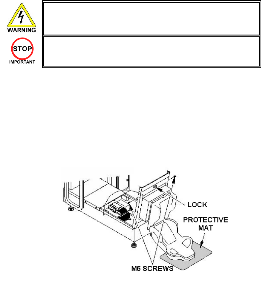
54
3.12. GAMEBOARD
• Turn off the mains power and remove the power cord before opening the
machine.
• The GAME BOARD should not require any work to be carried out upon it. All
settings and tests can be achieved without access to the GAME BOARD.
• All work to be carried out by QUALIFIED SERVICE PERSONNEL
3.12.1.REMOVING THE BOARD
To return the game board for servicing, take out the board using the following procedure.
1. Turn the main switch OFF.
2. Unlock the base and remove the 2 M6 bolts.
3. Tip the seat carefully backwards as shown. Be careful not to damage the seat back when resting it on
the floor. Use a protective mat under the seat back to protect it on hard floors.
4. Disconnect all connectors from the game board, remove the four screws securing the game board to the
wooden base, and lift it out. Do not attempt to service the game board. THERE ARE NO USER
SERVICEABLE PARTS INSIDE! Return the game board to the Service Department inside the special
packaging provided.
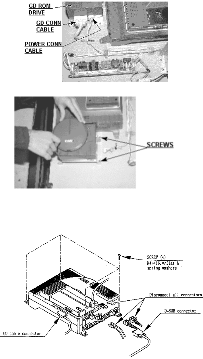
55
3.12.2.REMOVING THE GD-ROM DRIVE
Remove the GD cable connector and the power cord connector from the GD-ROM drive.
Remove the 4 screws to remove the GD-ROM drive.
3.12.3.REMOVING THE GAME BOARD
A) Remove all the connectors from the filter board on the Game Board. Also remove the GD cable
connector from the DIMM board.
B) Remove the 4 screws that fix the Game Board.
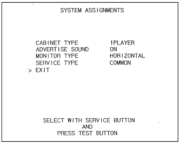
56
3.12.4.MACHINE SET UP
During linked play, if the test mode is not finished within three minutes on all linked machines, the
NETWORK CHECK cannot be performed, causing a NETWORK ERROR.
First, set up each linked machine to meet the requirements of communication play. If the settings are
incorrect, communication play is not possible.
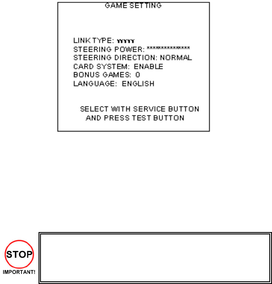
57
3.12.4.1.SETTING FOR COMMUNICATION PLAY
1. Turn all the linked machines on.
2. Enter TEST MODE in all machines.
3. Select SYSTEM ASSIGNMENTS.
4. Perform the COMMUNICATION MODE setting in the SYSTEM ASSIGNMENTS SCREEN. Set one of
the machines to MASTER and to SLAVE. If one machine is intended to be used as a live monitor, set
this one to RELAY (although this happens automatically if that machine is not being used).
5. Exit TEST mode on all machines: the NETWORK CHECK screen should be displayed.
6. If the ADVERTISE screen is displayed on completion of the NETWORK, the communication setting is
satisfactory. The NETWORK CHECK normally takes less than one minute. If this is not the case, then
recheck settings, connections etc. to determine the cause.
• Perform advertise sound settings on the MASTER seat; SLAVE machine will adopt
these settings.
• If, during communication play, the link is interrupted, the game is discontinued and the
NETWORK CHECK is displayed.
• If one linked machine enters TEST mode, all others display NETWORK CHECK,
hence be careful not to do this while a linked machine is being played.
Be aware that linked machines are different in operation to independent machines. As per the above, the
MASTER unit sets some Game Assignments. If these settings are changed on the SLAVE machine, the
new settings will be ineffectual.
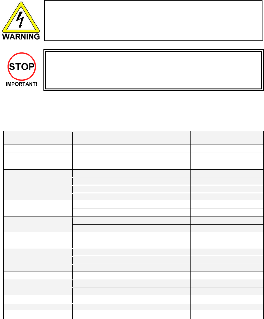
58
3.13. PERIODIC CHECK AND INSPECTION
The items listed below require periodic check and maintenance to retain the performance of the machine
and ensure safe operation:
• Be sure to check annually to see if the power cords are damaged. The plug is
securely inserted and that there is no dust in the interior of the machine or
between the socket and the power cord. Using the product in an unclean
condition may cause a fire or electric shock.
• Only QUALIFIED SERVICE PERSONNEL should carry out periodic checks.
The items listed below require periodic check and maintenance to retain the performance of this machine
and to ensure safe business operation.
When handling the controller, the player will be in direct contact with it . In order to always allow the player
to enjoy the game, be sure to clean it regularly. Also, it is advisable to provide wet tissue, etc. available for
player use.
ITEMS DESCRIPTION PERIOD
CABINET Check Adjusters' contact with surface. Daily
CARD READER/WRITER Head cleaning Every 151 counts of the card
reader/writer or Daily
Cleaning As necessary
Inspection of VR Monthly
Inspection of adjusting gear mesh Tri-monthly
CONTROL PANEL
Greasing Tri-monthly
Inspection of SW Monthly SHIFT LEVER
Greasing Tri-monthly
Inspection of VR Monthly ACCEL. & BRAKE
Gear and Spring portion greasing Tri-monthly
SCREEN cleaning. Weekly MONITOR
Check adjustments. Monthly or when moving.
Inspection of COIN SW Monthly
Coin insertion test Monthly
COIN CHUTE DOOR
Cleaning of COIN SELECTOR. Tri-monthly
SEAT Greasing to the seat rail Tri-monthly
MEMORY TEST Monthly GAME BD
Check settings. Monthly
POWER SUPPLY PLUG Inspection and cleaning Annually
INTERIOR Cleaning As necessary
CABINET SURFACES Cleaning As necessary

59
4. HOW TO PLAY
4.1. GAME DESCRIPTION
The following explanations apply to the case the product is functioning satisfactorily. Should there be any
moves different from the following contents, some sort of faults may have occurred. Immediately look into
the cause of the fault and eliminate the cause thereof to ensure satisfactory operation.
When the power is connected, the fluorescent lamp in the FL box is always on. When in an advertising
state, the screen displays the demonstration pictures and ranking data. Sounds are heard from the
speakers on the right and left of the monitor. The advertising sounds are not heard if you have set this
function to off (disabled).
The start button and the change view button on the control panel are integrated with a lamp. The start
button (lamp) flashes when the coins are inserted enough to play the game.
4.1.1. Game Overview
The game is a car racing game with three different game modes: "Legend of the Streets", "Time Attack"
and "The Bunta Challenge!". By connecting two units, you can also enjoy "Network Battle Game" play. The
card system allows players to store information such as the car, wins/loss records and car tune-up status
on a special card.
4.1.1.1.Legend of the Streets
Game Content & Rules
Battle rival characters man to man on 9 different courses. Each checkpoint you pass adds time to the
overall time limit. The first one across the finish line with the allotted time wins. If you run out of time or
cross the finish line second, you lose.
Once you've defeated all 28 rival characters, you'll get a chance to race against a hidden rival character I
and a hidden rival character II (final battle/race). Defeat them and you'll race for the title of street legend
against the last hidden rival character (special battle/race). Only when the title is yours will you get to see
the ending.
INITIAL D CARD
Purchasing a card when you start the game creates your car.
The card can store all the data for one car. Information on the
card includes the player name, car, tune-up status, names of
defeated rival characters, times from Time Attack mode, Network
Game records, passwords from Time Attack mode and more.
On the Card Screen, the player's name, car name, cleared areas,
Key and Speed Demon Level are displayed. The Key is
necessary when recording results on the Net Rankings.
Speed Demon Level stars increase as various conditions are
cleared.
Car Tune Ups
Depending on how well you do, points are added to your card when you use it to play in "Legend of the
Streets", "Time Attack", "The Bunta Challenge!" and "Network Battle Race" modes. When you've
accumulated enough points, you are given the option of using those points to do tune-ups on your car to
increase performance.
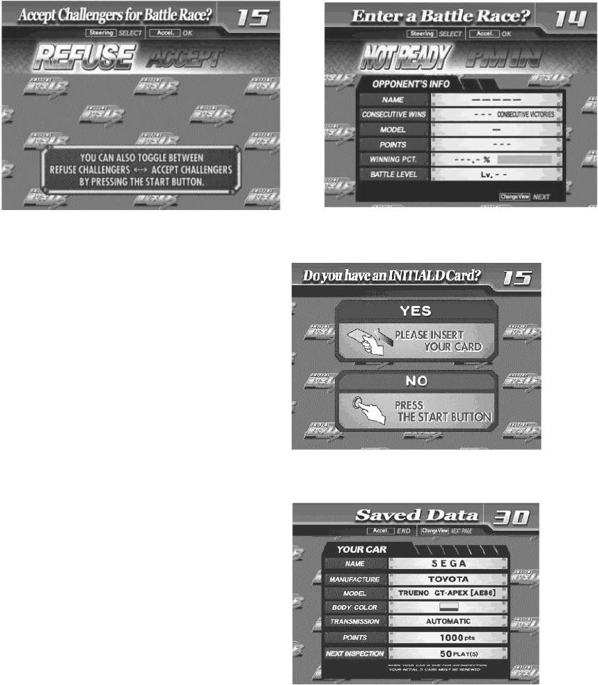
60
4.1.2. Game Flow
4.1.2.1.Challenger Accept Screen, Battle Race Select Screen:
When network play is disabled, this screen will not appear.
For a 1-player game only, select "Refuse Challengers" or or “Not Ready” (Not enter a Battle Race)..
4.1.2.2.Card Entry Screen and Card Purchase Screen:
Insert your card if you've got one after
completing the Card Purchase Screens. If you
don't already have a card, you can purchase
one.
4.1.2.3.Card Data Check Screen:
Insert your card and you can check the
recorded data on this screen.
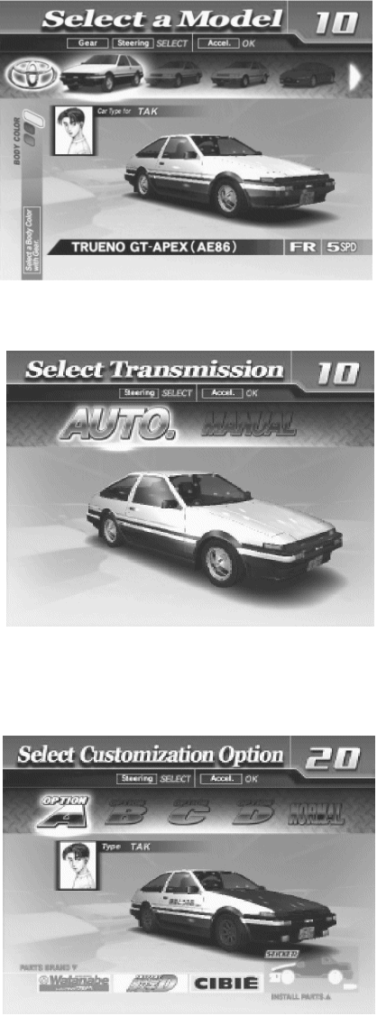
61
4.1.2.4.Vehicle Selection Screen:
This screen isn't displayed if you've already
purchased a card.
4.1.2.5.Transmission Selection Screen:
Transmission Selection Screen: This screen
isn't displayed if you've already purchased a
card.
4.1.2.6.Parts Course Selection Screen:
If you're purchasing a card, select one of the
Parts courses.
These parts are then attached to your car
when you accumulate enough points.
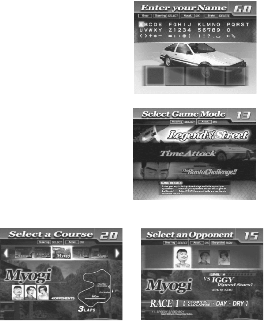
62
Name Entry Screen:
If you're purchasing a card, enter your name
(driver's name) at the player name input
screen.
Mode Select Screen:
Select "Legend of the Streets" at the Mode
Selection Screen.
Course and Rival Character Selection Screens
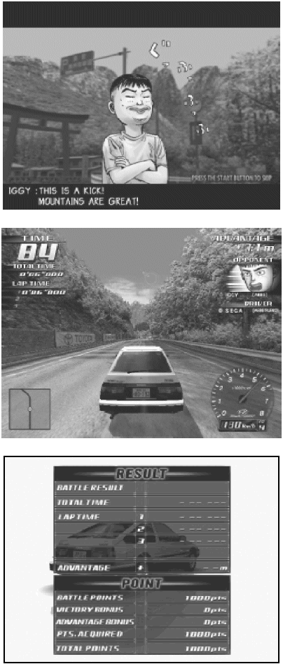
63
Rival Character Scenes
Battle (Race)
Results Screen
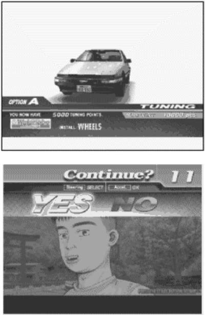
64
Tune Up Screen:
Use your card to play and accumulate points
you can put towards performance enhancing
tune-ups.
Continue Screen:
Choose to continue or quit after rival character
scenes. If you select "YES", nothing is recorded
to the card and you can continue playing. If you
select "NO", your game data is stored on your
card and your game ends.
65
4.1.2.7.Time Attack
Game Content & Rules
This is a race against time. The goal is to cross the finish line as quickly as you can.
Direction, Time of Day and Weather can be selected for each of the nine courses – note that Happogahara
and Akina (Snow) can only be set to Night.
Each checkpoint you pass adds time to the overall time limit. When you cross the finish line, a password is
displayed. (The password is not displayed when you don't use the card.)
You may use this password to participate in the online Internet rankings.
In order to register the password, you must have played the game with a card and you'll need to enter the 3
digit number or KEY printed on the front of the card.
Your times, when recorded with the Card (tuned car), are displayed in the ranking. The way to accumulate
points is to play with a card.
4.1.2.8.The BUNTA Challenge!
Game Content & Rules
Race head-to-head against a single rival, Fujiwara Bunta, on eight different courses:
Myogi, Usui, Akagi, Akina (Snow on Level 11), Happogahara, Shomaru and Tsuchisaka.
For each course, only Dry or Night conditions may be selected.
A Card with saved points is necessary to play.
Player must finish ahead within the time limit to win.
Finishing behind or over the time limit means the player loses.
Beating Bunta earns points and increases the Bunta Level for that course by one.
The Bunta Level indicates Bunta's strength; the higher the level the stronger he becomes.
Losing reduces the player's points total.
4.1.2.9.Network Battle Race
Game Content & Rules
Two vehicles race for victory.
When either car passes a checkpoint, remaining race time will be increased.
The winner is the car that crosses the finish line first or is occupying first place when time runs out.
A car built on the Card (tuned car) may also be used.
When racing with a tuned car, results will be saved on the Card.
Challengers may challenge at any point during the champion side race.
Cards may not be purchased during a Network Battle Race.
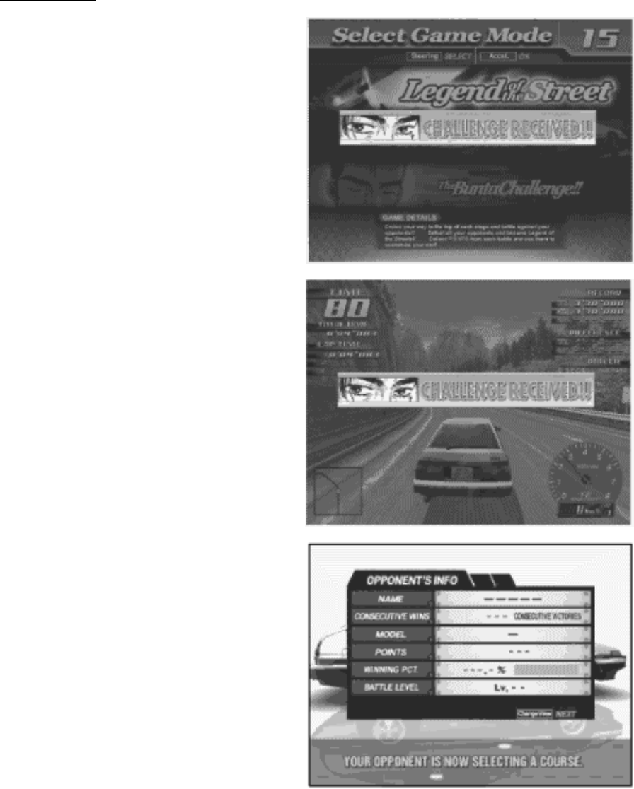
66
Before the Race
[Champion Side]
Battle Entry Challenge Request Screen.
When a challenge occurs before the start of the
race (during selection phase):
If the challenge occurs before the mode selection
phase (during Car Selection etc), the Network
Battle Race Information Screen is displayed
directly before the selection phase.
If the challenge occurs after the selection phase,
selection is interrupted and the Network Battle
Race Information Screen is displayed
When a challenge occurs during the race:
The race is interrupted and the Network Battle
Race Information Screen is displayed.
Network Battle Race Information Screen
The challenger selects the course while the
champion waits at the Network Battle Race
Information Screen.
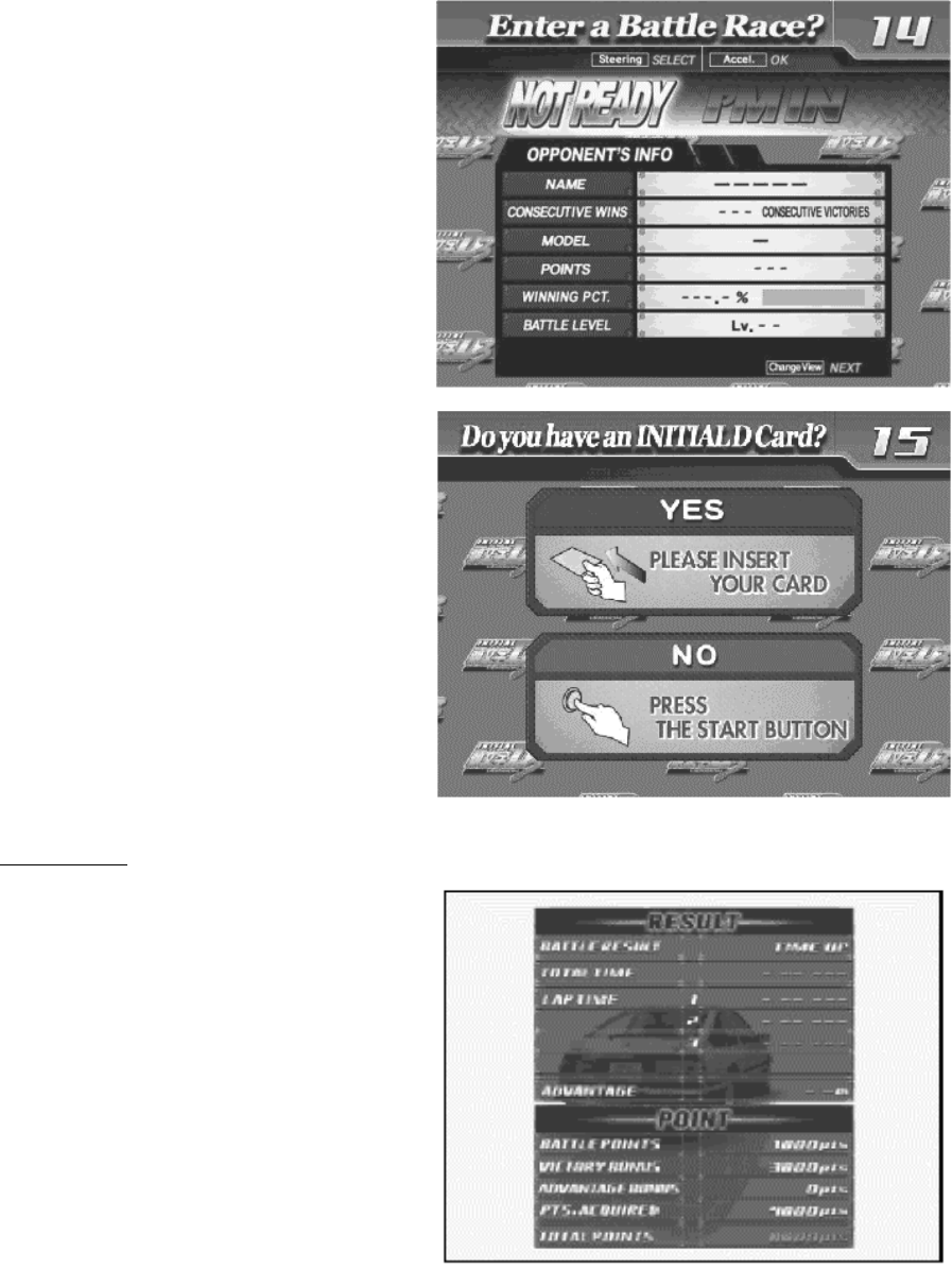
67
[Challenger Side]
Network Battle Race Select Screen
This screen asks if a new player wishes to
enter a Battle Race. It only appears when a
new player first inserts coins and the current
player has opted to accept Battle Race
challengers.
Card Entry Screen
When a Battle Race is established, the Card
Entry Screen appears.
A Battle can be raced even without a Card.
If there is no Card, the game proceeds to the
Car Selection and Transmission Selection
Screens.
The Course Selection Screen then appears.
The challenger selects the course.
After the Race
Results Screen
After a battle, the Results Screen appears.
Depending on the results, the Battle Level will
change.
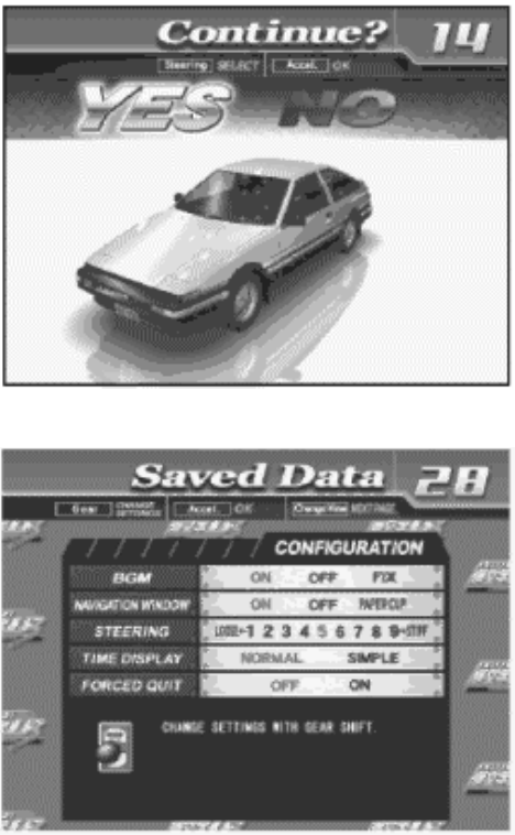
68
Continue Screen
The winning player will receive victory points
and will be allowed to continue play.
The losing player will go to the Continue
Screen.
When the number of victories exceeds the
set limit
When a player's total number of victories
exceeds the set limit, the player will be taken
to the Continue Screen even if they win.
4.1.2.10.Configuration
When a Card is inserted, a number of options
may be set.
Press the View Change Button at the Card
Data Confirmation Screen to go to the
Configuration screen. When displaying the
configuration Screen, you can select the item
by the Shift Lever. After selecting the item,
press the Start Button and change the setting
by the Steering Wheel. After changing the
setting, press the Start Button again to be
settled the new settings.
BGM
Set race background music options
On: Play BGM as normal (Default Setting).
Off: Turn BGM off.
Fix: Play the melody selected at Song Selection. Will play the same BGM until changed.
Navigation Display
Set options for the Navigation Display that appears at the lower left of the Race Screen.
On: Show navigation display (Default setting).
Off: Do not show navigation display.
Paper Cup: A paper cup full of water appears on the navigation display.
Steering
Set steering wheel stiffness.
1 to 9: 1 is the loosest. Stiffness increases up to a maximum setting of 9.
Default Setting is 5
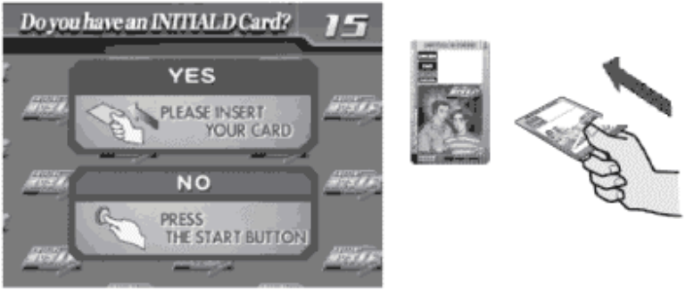
69
Time Display
Set the Time Display on the Race Screen.
Normal: Standard time display. (Default setting)
Simple: Simplified time display.
Forced Quit
Force end of game during Legend of the Streets and Time Attack play.
Off: Disable force quit (Default setting)
On: Enable force quit. Press the Start and Change View Buttons simultaneously to end game.
4.1.2.11.Game Over
With "Legend of the Streets", "Time Attack" and "Network Battle Race" play, the Continue Screen appears
after each race.
If you choose not to continue, the game ends.
4.1.2.12.Transferring Old Card Data
Card data from the previous versions, "Initial D" and "Initial D Ver. 2"may be transferred for use with "Initial
D Ver. 3". Not all player data will be transferred to the new Card.
• Transferable Data: Points, car model, player name, customization options, Auto/ Manual
transmission setting, number of plays till next inspection (the number of plays remaining on the
Card, plus 50, max. 127).
• Non-transferable Data: Tune-up (Tune-up status is returned to default, but transferred points may
be used to re-tune the car), times, race results, Legend of the Street status, Key and Speed Demon
Level, Network Battle Level, Bunta Level.
1. The player inserts coins to start.
Player inserts Card at the Card Entry Screen.
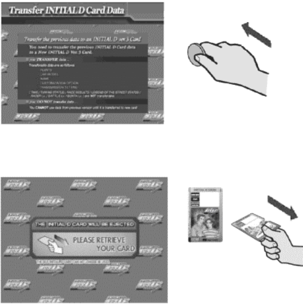
70
2. Player inserts credits at the Transfer Card Data Screen.
3. The old Card will be ejected. This Card can no longer be used
4. When the Card Data Transferred message appears, the game will restart.
The new Card is for exclusive use with the Initial D Ver. 3, and cannot be used with the previous versions,
Initial D and Initial D Ver. 2.
4.1.2.13.Limit on Card Use
Each Card can be used for up to fifty plays, until Car Inspection time is reached. Continued game play after
each race is not counted as part of the 50 game limit. Cards may be renewed by transferring data to a new
Card (stored points will not be lost). However, if you do not renew your card at the Car Inspection, you will
not longer be able to play using the data stored on your card.
71
4.1.2.14.Car Selections
TOYOTA
TRUENO GT-APEX [AE86]
LEVIN GT-APEX [AE86]
LEVIN SR [AE85]
MR2 G-Limited [SW20]
MR-S S EDITION [ZZW30]
ALTEZZA RS-200 [SXE10]
CELICA GT-FOUR [ST205]
NISSAN
SKYLINE GT-R [BNR32]
SKYLINE GT-R [BNR34]
SKYLINE 25GT TURBO [ER34]
SILVIA K's [S13]
SILVIA Q's [S14]
SILVIA K's AERO [S14]
SILVIA spec-R [S15]
180SX TYPE X [RPS13]
SILEIGHTY [RPS13]
HONDA
CIVIC SiR II [EG6]
CIVIC TYPE R [EK9]
INTEGRA TYPE R [DC2]
S2000 [AP1]
MITSUBISHI
LANCER GSR EVOLUTION III [CE9A]
LANCER RS EVOLUTION IV [CN9A]
LANCER RS EVOLUTION V [CP9A]
LANCER GSR EVOLUTION VI [CP9A]
LANCER GSR EVOLUTION VII [CT9A]
LANCER EVOLUTION WRS [CN9A]
LANCER EVOLUITON ZGSR [CT9A]
MAZDA
RX-7 Type R [FD3S]
RX-7 SPIRIT R Type A [FD3S]
RX-7 [FC3S]
RX-8 Type S [SE3P]
ROADSTER S Special [NA6CE]
ROADSTER RS [NB8C]
SUBARU
IMPREZA WRX STi Version VI [GC8]
IMPREZA WRX STi [GDB]
IMPREZA WRX Type R STi Version V [GC8]
SUZUKI
Cappuccino [EA11R]
4.1.2.15.Race Courses
Easy: Myogi, Circular Course/3 laps, Clockwise & Counter-clockwise,
Day & Night, Dry & Wet
Normal: Usui, Circular Course/2 laps, Clockwise & Counter-clockwise,
Day & Night, Dry & Wet
Hard: Akagi, Single road, Uphill & Downhill, Day & Night, Dry & Wet
Hard: Akina, Single road, Uphill & Downhill, Day & Night, Dry & Wet
Expert: Irohazaka, Single road, Downhill/Reverse, Day & Night, Dry & Wet
Expert: Akina (Snow),Single road, Uphill & Downhill, Night
Expert: Happogahara, Single road, Outbound & Inbound,Night, Dry & Wet
Expert: Shomaru, Single road, Outbound & Inbound, Day & Night, Dry & Wet
Expert: Tsuchisaka, Single road, Outbound & Inbound, Day & Night, Dry & Wet
72
4.1.2.16.Legend of the Streets Rival Characters
EASY (MYOGI)
IGGY LEVIN SR [AE85]
KENJI LEVIN SR [AE85]
SHINGO CIVIC SRi [EG6]
NORMAL (USUI)
TORU ROADSTER S Special [NA6CE]
KAWAI SKYLINE 25GT TURBO [ER34]
MAYA&SIMONE SILEIGHTY [RPS13]
HARD (AKAGI)
TWO GUYS FROM TOKYO SILVIA spec-R [S15]
DANNY SILVIA Q's [S14]
K. T. RX-7 Type R [FD3S]
HARD (AKINA)
COLE SILVIA K's [S13]
ZACK SKYLINE GT-R V-spec II [BNR32]
KYLE LANCER GSR EVOLUTION III [CE9A]
RY RX-7 •‡III [FC3S]
TAK TRUENO GT-APEX [AE86]
BUNTA IMPREZA WRX R STi Version V [GC8]
EXPERT (IROHAZAKA)
HAWK LANCER RS EVOLUTION IV [CN9A]
KYLE LANCER GSR EVOLUTION III [CE9A]
CAINE MR2 G-Limited [SW20]
EXPERT (AKINA SNOW)
MIKI CELICA GT-FOUR [ST205]
EXPERT (HAPPOGAHARA)
DICE CIVIC TYPE R [EK9]
SMILEY INTEGRA TYPE R [DC2]
TOUCH CIVIC TYPE R [EK9]
EXPERT (SHOMARU)
NOBU ALTEZZA RS-200 [SXE10]
SID CAPPUCCINO [EA11R]
AKI LEVIN GT-APEX [AE86]
EXPERT (TSUCHISAKA)
KYLIE RX-7 Type R [FD3S]
RY RX-7 [FC3S]
Man in Evo V LANCER RS EVOLUTION V [CP9A]
Man in Evo VI LANCER GSR EVOLUTION VI [CP9A]
K. T. RX-7 Type R [FD3S]
TAK TRUENO GT-APEX [AE86]
73
5. MAINTENANCE INSTRUCTIONS
5.1. EXPLANATION OF TEST AND DATA DISPLAY
Use the switches on the VTS to enter the TEST MODE. This will allow you to carry out post installation and
periodic checks and adjustments. The following section details the function of each of the tests:
• Be very careful about entering TEST MODE. If the machine you wish to test is
linked to other machines, exiting test on your machine will cause a network check
to be carried out. This will disable all other machines linked to it.
ITEM DESCRIPTION / REFERENCE INTERVAL
INSTALLATION
OF THE
MACHINE
When the machine is installed perform the following checks:
Check to see that each setting is as per the standard settings input at
the time of shipment.
In the INPUT TEST mode, check each switch and VR. Section 5.3.2
In the OUTPUT TEST mode, check each of the lamps. Section 5.3.3
In the MEMORY TEST mode check all of the IC’s on the IC BD.
Section 5.2.1
Monthly
MEMORY On the TEST MENU screen choosing the MEMORY TEST allows self
test to be performed. In this test RAM & ROM are tested.
Monthly
PERIODIC
CHECKS
Periodically perform the following
MEMORY TEST. Section 5.2.1.
Ascertain each setting:
In the INPUT TEST mode, test the control devices. Section 5.3.2
In the OUTPUT TEST mode, check each of the lamps. Section 5.3.3
Monthly
CONTROL
SYSTEM
In the INPUT TEST mode, check each switch and VR. Section 5.3.2
Adjust or replace each switch and VR. Section 3.9
Monthly
MONITOR In the CRT TEST mode, check to ensure the monitor is adjusted
correctly. Section 5.2.4
Clean screen (switch off machine and remove the plug)
Monthly
Weekly
IC BOARD MEMORY TEST
In the SOUND TEST mode, check the sound related ROMs. 5.2.3
Monthly
DATA CHECK Check such data as held in the bookkeeping screens, relating to
number and length of plays. Section 5.4
Monthly
EXTERIOR
MAINTENANCE
Clean surfaces
Lubricate seat sliders
Monthly
COIN
MECHANISM
Check switch operation (if fitted) Monthly
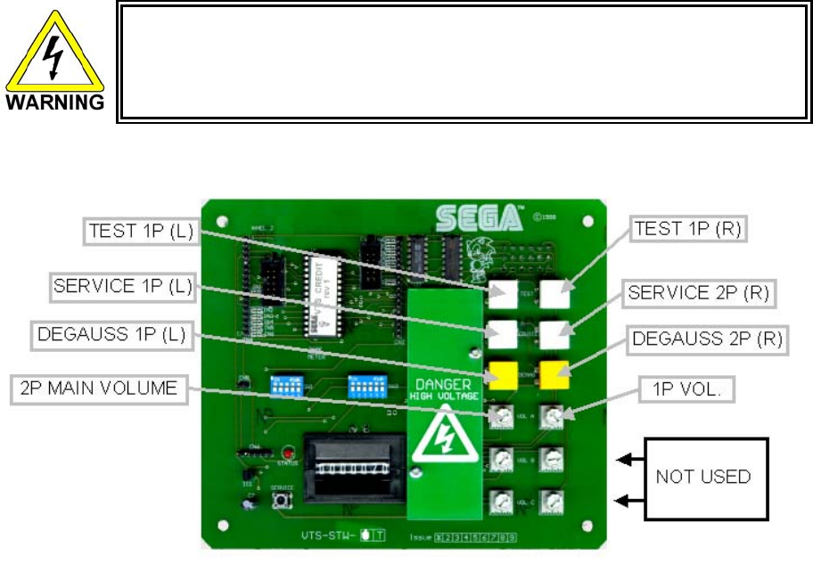
74
5.1.1. VTS ASSEMBLY
• Do not touch places other than those specified. Touching places not specified could
cause an electric shock or short circuit.
Opening the Coin Chute door will reveal the VTS Assembly shown above. The function of each switch is as
follows. The controls on the left affect the 1P cockpit, those on the right the 2P
TEST BUTTON
(TEST SW)
Used to enter TEST mode. Also has function
during TEST mode. Refer to the later section
detailing TEST mode.
SERVICE BUTTON
(SERVICE SW)
Gives credits without registering on the coin
counter. Also used during TEST mode.
DEMAG Demagnetises (degausses) the CRT to remove
colour unevenness.
VOLUME MAIN Adjusts the volume of the left and right main
speakers.
VOLUME WOOFER Adjusts the volume of the woofer.
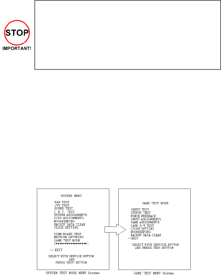
75
5.2. SYSTEM TEST MODE
• The contents of settings changed in the TEST mode are stored when the test
mode is finished from EXIT in the menu mode. If the power is turned off before
the TEST mode is finished, the contents of setting change become ineffective.
• Executing "BACKUP DATA CLEAR" in the SYSTEM TEST MODE does not
clear the BOOKKEEPING data in the GAME TEST mode.
• Entering the TEST mode clears fractional number of coins less than one credit
and BONUS ADDER data.
• Perform setting as per specified in this manual for operation. If setting not
specified is performed for operation, proper function of this product may not be
obtained.
In the SYSTEM TEST MODE, IC BD functioning can be checked, the monitor adjusted, and the coin setting
performed.
Refer to NAOMI NETWORK SYSTEM SERIVCE MANUAL for the details. Note that the setting of the
following items need to be performed in accordance with the instruction given.
CABINET TYPE : 1 PLAYER(S)
MONITOR TYPE : HORIZONTAL
SERVICE TYPE : COMMON
COIN CHUTE TYPE : COMMON
NETWORK TYPE : NONE
The SEQUENCE SETTING items of COIN/CREDIT SETTING are as follows.
SEQUENCE SETTING
SEQUENCE 1: Number of credits required for starting the game.
SEQUENCE 2: Number of credits required for continuing the play.
SEQUENCE 3: Number of credits required for dedicated CARD purchase.
SEQUENCE 4 -8: NOT USED
Press the TEST BUTTON to bring up the screen shown to the left.
Press the SERVICE BUTTON to move downwards through the list. The arrow shows the current selection.
Press the TEST BUTTON to activate the selected test.
To finish TEST MODE, move the arrow to EXIT and press the TEST.
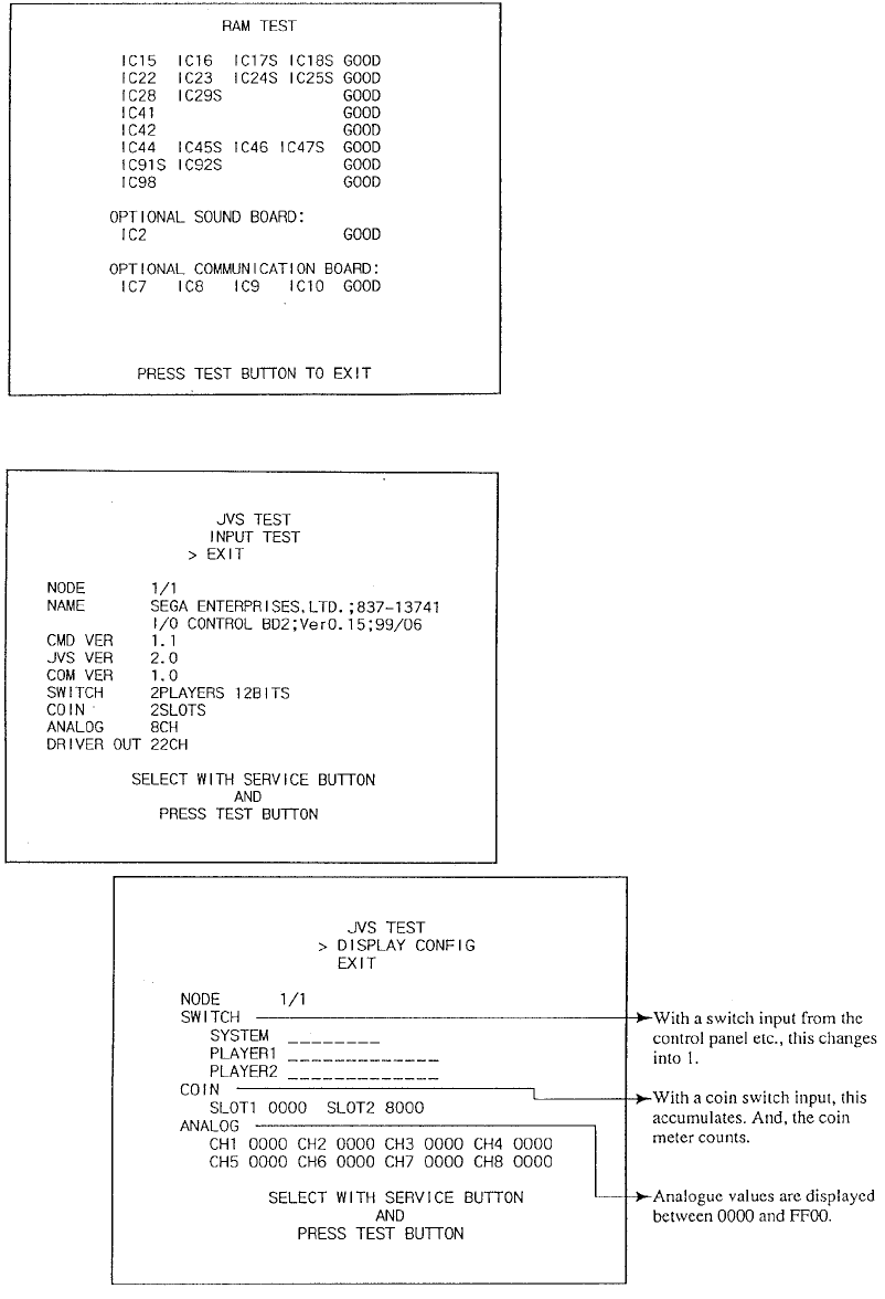
76
5.2.1. RAM TEST
The memory test mode is for automatically
checking the on-board memory IC functioning.
“GOOD” is displayed for normal IC’s and “BAD “
for abnormal IC’s
• When the test is completed, if the results are
as shown on the left then the Game Board is
satisfactory.
• The test should take approximately thirty
seconds to complete. If the test exceeds this
time the board may have malfunctioned.
• After finishing the test press the TEST
BUTTON or START BUTTON to exit.
5.2.2. JVS TEST
• In this test, functioning of the I/O Board
connected to the Game Board is displayed,
and INPUT TEST can be performed. Select
EXIT to return to the MENU screen, or select
INPUT TEST to display the second screen.
Select EXIT to return to the MENU screen.
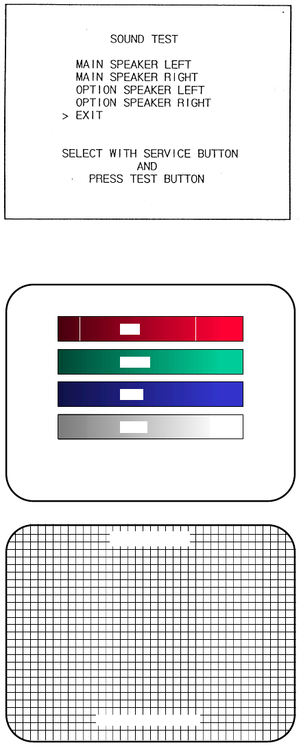
77
5.2.3. SOUND TEST
Select the sound test to check the status of the amplifiers, soundboards, and speakers.
Press the SERVICE button or view change button to move the arrow to the desired test item.
Press TEST button to output the sound.
• Select the sound source with SERVICE.
• On pressing TEST, the test sound is emitted
from the selected source.
Select EXIT to return to MENU screen.
5.2.4. C.R.T TEST
C.R.T TEST
PAGE 1/2
C.R.T. TEST 1/2
PRESS TEST BUTTON TO CONTINUE
RED
GREEN
BLUE
WHITE
Selecting CRT test allows the projector adjustment
to be checked for colour and distortion.
Press the test or start button to have the second
CRT test screen appear.
C.R.T. TEST 2/2
PRESS TEST BUTTON TO EXIT
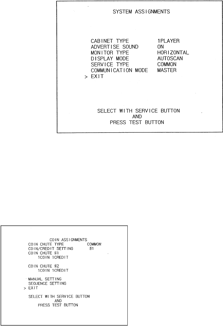
78
5.2.5. SYSTEM ASSIGNMENTS
Allows system options to be set. Select required setting with SERVICE button, confirm with TEST button.
Default settings are indicated in parentheses.
• CABINET TYPE specifies Control Panel and number of Coin Chutes. The number of players displayed
in BOOKKEEPING varies in accordance with the value displayed here. (1PLAYER)
• ADVERTISE SOUND allows the sound emission to be turned (ON) or OFF during ADVERTISE MODE.
• MONITOR TYPE changes the orientation of the image on the screen (HORIZONTAL)
• SERVICE TYPE sets the functioning of the SERVICE button, should several SERVICE buttons exist.
INDIVIDUAL: Service credit is applied to the machine on which the SERVICE button is pressed.
(COMMON): Service credit is applied to all machines when SERVICE button is pressed.
5.2.5.1.COIN ASSIGNMENTS
Select the coin assignments mode to set the coin
to credit ratios.
This can be any of the pre-set values or can be
done manually.

79
5.2.5.2.COIN/CREDIT SETTING (COIN CHUTE COMMON TYPE)
SETTING FUNCTIONING OF COIN CHUTE #1 FUNCTIONING OF COIN CHUTE #2
SETTING #1 1 COIN 1 CREDIT 1 COIN 1 CREDIT
SETTING #2 1 COIN 2 CREDITS 1 COIN 1 CREDIT
SETTING #3 1 COIN 3 CREDIT 1 COIN 1 CREDIT
SETTING #4 1 COIN 4 CREDITS 1 COIN 1 CREDIT
SETTING #5 1 COIN 5 CREDITS 1 COIN 1 CREDIT
SETTING #6 1 COIN 2 CREDITS 1 COIN 2 CREDITS
SETTING #7 1 COIN 5 CREDITS 1 COIN 2 CREDITS
SETTING #8 1 COIN 3 CREDITS 1 COIN 3 CREDITS
SETTING #9 1 COIN 4 CREDITS 1 COIN 4 CREDITS
SETTING #10 1 COIN 5 CREDITS 1 COIN 5 CREDITS
SETTING #11 1 COIN 6 CREDITS 1 COIN 6 CREDITS
SETTING #12 2 COINS 1 CREDIT 2 COINS 1 CREDIT
SETTING #13 1 COIN 1 CREDIT 2 COINS 1 CREDIT
SETTING #14 1 COIN 2 CREDITS 2 COINS 1 CREDIT
SETTING #15 1 COIN
2 COINS
1 CREDIT
3 CREDITS
1 COIN
2 COINS
1 CREDIT
3 CREDITS
SETTING #16 1 COIN 3 CREDITS 1 COIN
2 COINS
1 CREDIT
3 CREDITS
SETTING #17 3 COINS 1 CREDIT 3 COINS 1 CREDIT
SETTING #18 4 COINS 1 CREDIT 4 COINS 1 CREDIT
SETTING #19 1 COIN
2 COINS
3 COINS
4 COINS
1 CREDIT
2 CREDITS
3 CREDITS
5 CREDITS
1 COIN
2 COINS
3 COINS
4 COINS
1 CREDIT
2 CREDITS
3 CREDITS
5 CREDITS
SETTING #20 1 COIN 5 CREDITS 1 COIN
2 COINS
3 COINS
4 COINS
1 CREDIT
2 CREDITS
3 CREDITS
5 CREDITS
SETTING #21 5 COINS 1 CREDIT 5 COINS 1 CREDIT
SETTING #22 1 COIN 2 CREDITS 3 COINS
5 COINS
1 CREDIT
2 CREDITS
SETTING #23 2 COINS
4 COINS
5 COINS
1 CREDIT
2 CREDITS
3 CREDITS
2 COINS
4 COINS
5 COINS
1 CREDIT
2 CREDITS
3 CREDITS
SETTING #24 1 COIN 3 CREDITS 2 COINS
4 COINS
5 COINS
1 CREDIT
2 CREDITS
3 CREDITS
SETTING #25 1 COIN
2 COINS
3 COINS
4 COINS
5 COINS
1 CREDIT
2 CREDITS
3 CREDITS
4 CREDITS
6 CREDITS
1 COIN
2 COINS
3 COINS
4 COINS
5 COINS
1 CREDIT
2 CREDITS
3 CREDITS
4 CREDITS
6 CREDITS
SETTING #26 1 COIN 6 CREDITS 1 COIN
2 COINS
3 COINS
4 COINS
5 COINS
1 CREDIT
2 CREDITS
3 CREDITS
4 CREDITS
6 CREDITS
SETTING #27 FREE PLAY FREE PLAY

80
5.2.5.3.COIN/CREDIT SETTING (COIN CHUTE INDIVIDUAL TYPE)
SETTING FUNCTIONING OF COIN CHUTE #1
SETTING #1 1 COIN 1 CREDIT
SETTING #6 1 COIN 2 CREDITS
SETTING #8 1 COIN 3 CREDITS
SETTING #9 1 COIN 4 CREDITS
SETTING #10 1 COIN 5 CREDITS
SETTING #11 1 COIN 6 CREDITS
SETTING #12 2 COINS 1 CREDIT
SETTING #15 1 COIN
2 COINS
1 CREDIT
3 CREDITS
SETTING #17 3 COINS 1 CREDIT
SETTING #18 4 COINS 1 CREDIT
SETTING #19 1 COIN
2 COINS
3 COINS
4 COINS
1 CREDIT
2 CREDITS
3 CREDITS
5 CREDITS
SETTING #21 5 COINS 1 CREDIT
SETTING #22 3 COINS
5 COINS
1 CREDITS
2 CREDITS
SETTING #23 2 COINS
4 COINS
5 COINS
1 CREDIT
2 CREDITS
3 CREDITS
SETTING #25 1 COIN
2 COINS
3 COINS
4 COINS
5 COINS
1 CREDIT
2 CREDITS
3 CREDITS
4 CREDITS
6 CREDITS
SETTING #27 FREE PLAY
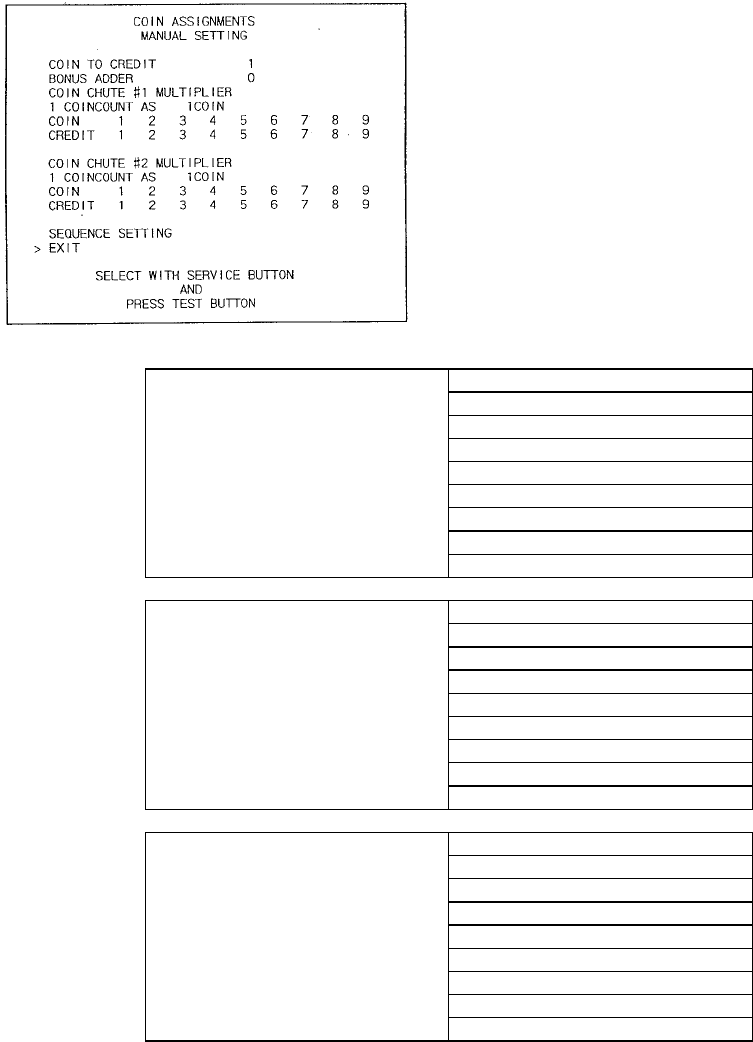
81
5.2.5.4.MANUAL SETTING
Select manual setting to manually set the coin to
credit ratios.
The available combinations are detailed below.
MANUAL SETTING
COIN TO CREDIT 1 COIN 1 CREDIT
2 COINS 1 CREDIT
3 COINS 1 CREDIT
4 COINS 1 CREDIT
5 COINS 1 CREDIT
6 COINS 1 CREDIT
7 COINS 1 CREDIT
8 COINS 1 CREDIT
9 COINS 1 CREDIT
BONUS ADDER NO BONUS ADDER
2 COINS GIVE 1 EXTRA COIN
3 COINS GIVE 1 EXTRA COIN
4 COINS GIVE 1 EXTRA COIN
5 COINS GIVE 1 EXTRA COIN
6 COINS GIVE 1 EXTRA COIN
7 COINS GIVE 1 EXTRA COIN
8 COINS GIVE 1 EXTRA COIN
9 COINS GIVE 1 EXTRA COIN
COIN CHUTE MULTIPLIER 1 COIN COUNTS AS 1 COIN
1 COIN COUNTS AS 2 COINS
1 COIN COUNTS AS 3 COINS
1 COIN COUNTS AS 4 COINS
1 COIN COUNTS AS 5 COINS
1 COIN COUNTS AS 6 COINS
1 COIN COUNTS AS 7 COINS
1 COIN COUNTS AS 8 COINS
1 COIN COUNTS AS 9 COINS
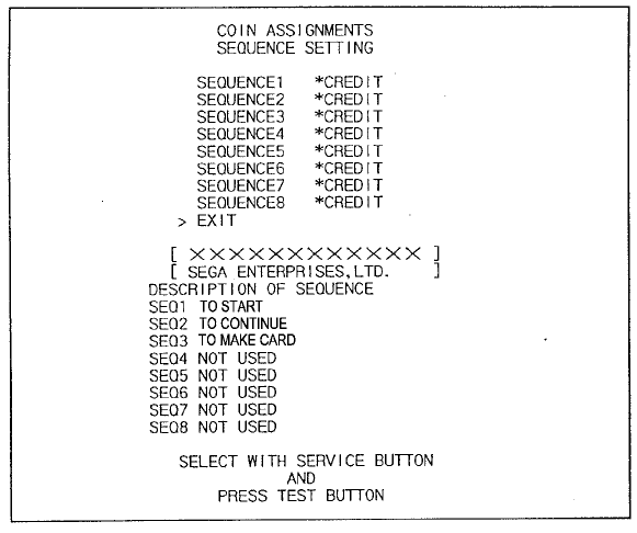
82
5.2.5.5.SEQUENCE SETTING
Selecting SEQUENCE SETTING allows the number of credits required to start the game to be set. Each
sequence can be set between 1 and 5. Select EXIT to return to the first screen.
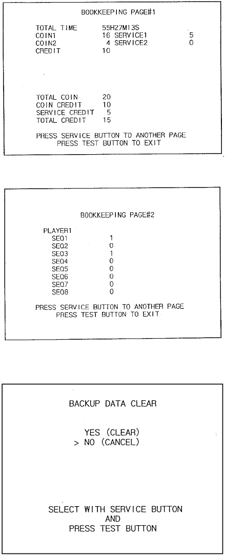
83
5.2.5.6. BOOKKEEPING
This mode consists of 2 pages that allow the data
relating to credit and game play time to be checked.
In page 1 mode press SERVICE to proceed to page
2, in page 2 mode press TEST to return to the test
menu.
• Total time is displayed as XXH XXM XXS and no
date will be displayed after exceeding 24 hours.
• The displays for number of coin and number of
service vary depending on the CABINET TYPE
set in SYSTEM ASSIGNMENTS. Number of
credit displays 1 if COIN CHUTE TYPE is set to
COMMON in COIN ASSIGNMENTS. If COIN
CHUTE TYPE is set to INDIVIDUAL, the
applicable number in CABINET TYPE setting will
be displayed.
• On the second screen, each sequence displays
the frequency of functioning.
5.2.5.7.BACKUP DATA CLEAR
Clears the contents of bookkeeping. When clearing,
bring the arrow to “YES (CLEAR)” and press the
test button. When the data has been cleared
“COMPLETED” will be displayed. Bring the arrow to
“NO (CANCEL)” and press the test button to return
to the menu mode.
Note that this does not clear the contents of
BOOKKEEPING in GAME TEST MODE. For this,
use the BACKUP DATA CLEAR in GAME TEST
MODE.
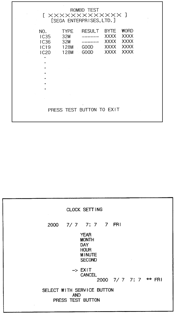
84
5.2.5.8.ROM BD TEST
In this test, Game Board ROM is checked. If GOOD is displayed, it is satisfactory. The IC number, TYPE,
BYTE and WORD refer to the checksum of each unit. Press TEST to exit.
On above screen, IC35 and IC36 (program ROMs) do not display GOOD or BAD. Press TEST Button to
EXIT.
5.2.5.9. CLOCK SETTING
YEAR, MONTH, DAY, HOUR and MINUTE are set for SEGA NAOMI BOARD. Select the desired item with
SERVICE button and press TEST to increase the value. Select EXIT to return to MENU mode.
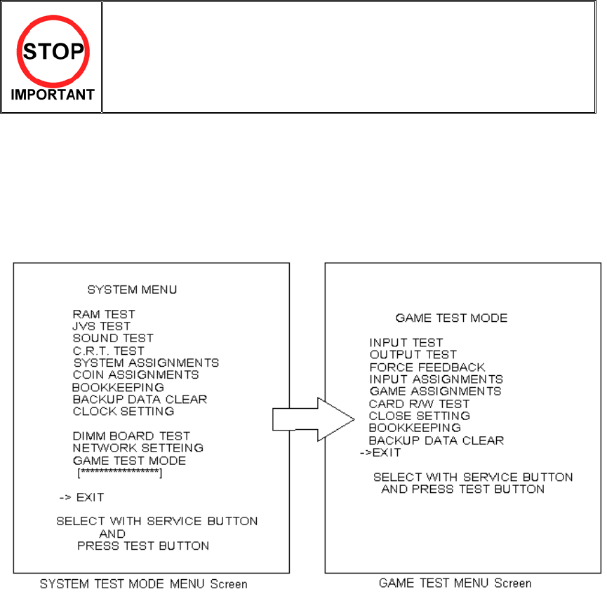
85
5.3. GAME TEST MODE
• When changing the game configuration, changes will not take effect until
the Game Test Mode has been completed. Be sure to exit the Game Test
Mode properly after configuration changes.
• Do not configure the game in ways not described in this text. It is possible
that the game will not function properly.
5.3.1. GAME TEST MENU MODE
Select GAME TEST MODE from the System Menu screen to display the Game Test Menu screen.
Use the SERVICE Button to move the cursor to the desired test item.
Press the TEST Button to enter the selected item.
After making changes, be sure to select EXIT and press the TEST Button in order to enable the new
settings.
Move the cursor to EXIT and press the TEST Button to return to the System Menu screen.
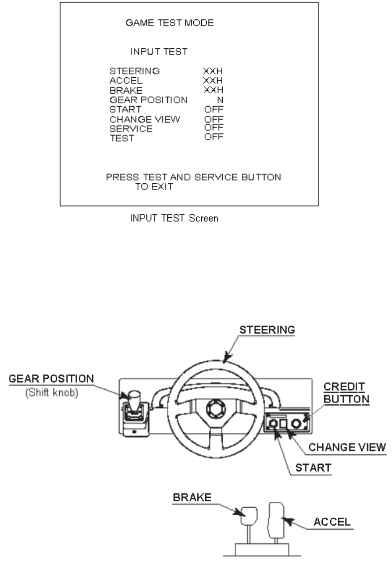
86
5.3.2. INPUT TEST
Select INPUT TEST to display the following screen and check the status of input devices.
This test should be used periodically to check that each input device is functioning correctly.
Test the STEERING, ACCEL and BRAKE controls to ensure that they are functioning properly and that the
parameters change smoothly as each input device is operated.
Display N, UP and DOWN using the GEAR POSITION. N should display there is no control input. Verify
that both UP and DOWN display in sync with the position of the shift knob.
Press the START, CHANGE VIEW, SERVICE and TEST Buttons. If functioning correctly, each indicator will
switch from OFF to ON.
Press the SERVICE and TEST Buttons simultaneously to return to the Game Test Menu screen.
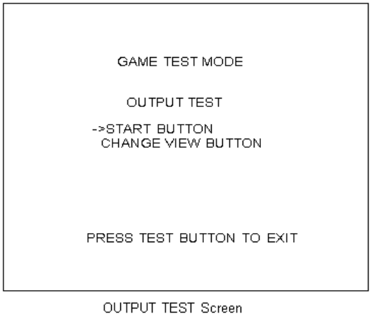
87
5.3.3. OUTPUT TEST
Select OUTPUT TEST to display the following screen and check the status of each lamp.
This test should be used periodically to check that the lamps are functioning correctly.
The cursor toggles automatically between START Button and CHANGE VIEW Button, and each lamp lights
up.
Press the TEST Button to return to the Game Test Menu screen.
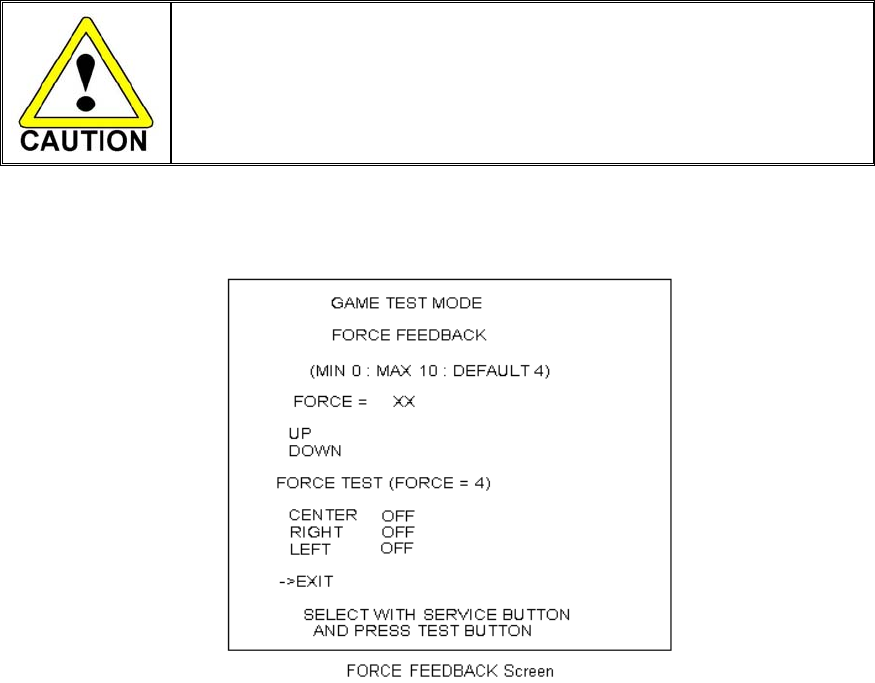
88
5.3.4. FORCE FEEDBACK
• If you select FORCE FEEDBACK, the STEERING will rotate automatically
when you press the TEST Button. The STEERING will also rotate
automatically during FORCE TEST. Make sure that no one is touching the
STEERING before running these tests as contact may cause injury.
When you select "FORCE FEEDBACK", a connection test runs and the STEERING rotates. When the
connection check completes, a screen similar to the one below is displayed, and you may adjust the
STEERING resistance.
FORCE: Set the STEERING resistance
The smaller the value, the weaker the resistance; the larger the value, the stronger the
resistance.
(Minimum value is 0; the maximum value is 10. The default setting is 4.)
Move the cursor to UP or DOWN and press the TEST Button to change the value.
FORCE TEST: Verifies the STEERING motor is working properly
Conducted when the STEERING resistance is set at 4.
Toggle between OFF and ON by aligning to CENTRE and pressing the TEST Button.
The STEERING will rotate and stop in the centre position. Pressing the SERVICE
Button moves the cursor to the next menu item and CENTRE changes to OFF.
Control of the STEERING is then released.
When the RIGHT menu item is ON, the STEERING rotates to the right as far as
possible and then stops. Press the SERVICE Button again to turn it OFF and release
control of the STEERING.
When the LEFT menu item is ON, the STEERING rotates to the left as far as possible
and then stops. Press the SERVICE Button again to turn it OFF and release control of
the STEERING.
Move the cursor to EXIT and press the TEST Button to return to the Game Test Menu screen.
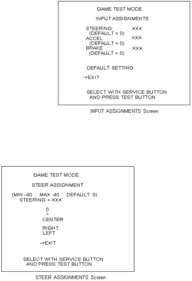
89
5.3.5. INPUT ASSIGNMENTS
Select INPUT ASSIGNMENTS to display the following screen.
You can adjust each of the menu items by moving the cursor to the menu item and pressing the TEST
Button.
Return all settings to the default settings with DEFAULT SETTING.
STEERING: Make adjustments to STEERING
Press the TEST Button to display the following screen.
Centre the STEERING. When the "0"
displayed is not exactly aligned with the "^"
mark above CENTRE, use the cursor to
select RIGHT or LEFT and move the "0" until
it is displayed directly above the "^" mark.
Move the cursor to RIGHT and press the
TEST Button to move the "0" to the right.
Each time you press the TEST Button, "0"
moves slightly to the right. Move the cursor
to LEFT and press the TEST Button to move
the "0" to the left. Each time you press the
TEST Button, "0" moves slightly to the left.
Move the cursor to EXIT and press the TEST
Button to return to the INPUT
ASSIGNMENTS screen.
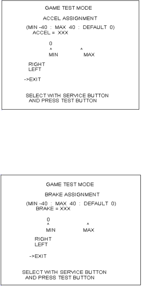
90
ACCEL: Make adjustments to ACCEL
Press the TEST Button to display the following screen.
Adjust the distance between "0" displayed
and the "^" mark equally so that when your
foot is off the ACCEL pedal, the "0" on the
left is aligns with the "^" above MIN and
when you press the ACCEL pedal down all
the way, the "0" on the right is aligns with the
"^" mark above MAX.
Move the cursor to RIGHT and press the
TEST Button to move "0" to the right. Each
press of the TEST Button moves "0" slightly
to the right.
Move the cursor to LEFT and press the
TEST Button to move "0" to the left. Each
press of the TEST Button moves "0" slightly
to the left.
Move the cursor to EXIT and press the TEST
Button to return to the INPUT
ASSIGNMENTS screen.
BRAKE: Make adjustments to BRAKE
Press the TEST Button to display the following screen.
Adjust the distance between "0" displayed and
the "^" mark equally so that when your foot is
off the BRAKE pedal, the "0" on the left is
aligns with the "^" above MIN and when you
press the BRAKE pedal down all the way, the
"0" on the right is aligns with the "^" mark
above MAX.
Move the cursor to RIGHT and press the TEST
Button to move "0" to the right. Each press of
the TEST Button moves "0" slightly to the right.
Move the cursor to LEFT and press the TEST
Button to move "0" to the left. Each press of
the TEST Button moves "0" slightly to the left.
Move the cursor to EXIT and press the TEST
Button to return to the INPUT ASSIGNMENTS
screen.
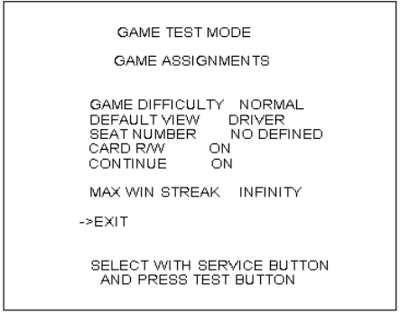
91
5.3.6. GAME ASSIGNMENTS
Select GAME ASSIGNMENTS to display the current game settings and make changes.
The GAME DIFFICULTY and CONTINUE menu items can be set only when the SEAT NUMBER is set to
either 1 or NO DEFINED. The MAX WIN STREAK menu item can be set only when the SEAT NUMBER is
set to 1.
Æ GAME
DIFFICULTY:
Set the level of difficulty for the game
You may select one of 5 different levels of difficulty: VERY EASY, EASY,
NORMAL, HARD or VERY HARD.
This setting does not affect the speed of rivals in "Legend of the Streets"
mode.
Æ DEFAULT VIEW: Set the view perspective at the start of races
You may select one of the following 2 settings: DRIVER view or REAR view.
Æ SEAT NUMBER: Assign seat numbers to seats in each arcade unit for network play
If you have two arcade units side by side, make sure you assign different
seat numbers; the seat on the left would be 1 and the one on the right would
be 2. If the unit will not be used for network play, set the SEAT NUMBER to
NO DEFINED.
You may select one of the following 3 settings: 1, 2 or NO DEFINED.
Æ CARD R/W: Set to ON if using the Card Reader/Writer.
Set to OFF when not using the Card Reader/Writer.
Æ CONTINUE: Enable/Disable Continue function.
ON: Enables Continue for Legend of the Street Time Attack and Network
Battle Race games.
OFF: Disable Continue.
Æ MAX WIN STREAK: Set maximum possible wins in the Battle Race game
1/3/5/10/20/30: Causes the continue screen to appear when the number of
wins exceeds the indicated limit.
INFINITY: Play continues without inserting new coins as long as the
player continues to win.
Changes to settings are not enabled until Test Mode is exited.
After changing settings, be sure to exit Test Mode.
After changing the settings, select EXIT and press the TEST
Button to return to the Game Test Menu screen.
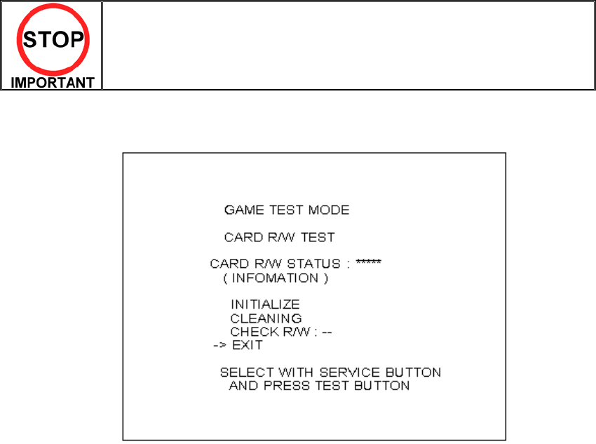
92
5.3.7. CARD R/W TEST
• Clean the card reader/writer periodically.
Test the functionality of or clean the CARD R/W (read/writer).
The CARD R/W should be tested and cleaned periodically.
The cursor can move to the following items:
Æ INITIALIZE: Initialisation
Æ CLEANING: Cleaning
Æ CHECK R/W: R/W Operation Check
Move the cursor to EXIT and press the TEST Button to return to the Game Test Menu screen.
93
Depending on the R/W running mode, one of the following is displayed in "*****" in "CARD R/W STATUS:
“*****":
READY.….….. Now waiting (Clear to Send Command)
INITIAL ……… Now initializing (Not Clear to Send Command)
CLEAN ……… Now cleaning (Not Clear to Send Command)
GET………….. Cards are being taken out from the dispenser (Not Clear to Send Command)
SAVE………… Sample data is saved onto the card (Not Clear to Send Command)
PRINT……….. Sample data is printed onto the card (Not Clear to Send Command)
LOAD………… Load card data and compares it with sample data (Not Clear to Send Command)
OUT………….. Eject cards (Not Clear to Send Command)
SHUTTER…… Now closing/opening the shutter (Not Clear to Send Command)
ERROR………
.
Error (Clear to Initialize Command Only)
While a status with a note of "Not Clear to Send Command " in parentheses is on-screen, no operations are
accepted. If such a status has occurred, wait until the operation in that status stops automatically and the
display comes to READY.
Occasionally, the "INFORMATION" field on the screen outputs one of the instructions below.
It usually displays nothing (blank), although it displays NO ERROR when each item is completed normally.
While cleaning is in progress, waiting in the ready mode for inserting a cleaning card:
--PLEASE INSERT CLEANING CARD –
After the operation check, waiting for the ready mode for ejecting the card:
-- PLEASE REMOVE –
When an error occurs, its type are displayed in the "INFORMATION" field:
NO ERROR………………… Normal Completion
CAN'T LOAD………………. Loading Error
CAN'T SAVE……………….. Writing Error
DRAW CARD ERROR…….. Error in Taking Card from dispenser
CARD STUFFED………….. Card Jamming
SHUTTER ERROR………… Shutter Error
WRONG DATA…………….. Data Error, Dispenser Card Empty
CONNECTION ERROR…… Connection Error
SCIF ERROR RC-232C…… Communication Error
UNKNOWN EROR………… Unknown Error
The "---" field in "CHECK R/W : ---" shows the result of the operation check.
---……………... Not Checked
OK …………… No Failure
NG……………. Failure
94
5.3.8. CLEANING PROCESS
Cleaning refers to the optional cleaning of the heads on the CARD R/W.
Refer to Head Cleaning for details on the use of the cleaning card.
Select "CLEANING" and press the TEST Button.
A. If the CARD R/W is not initialised, it will be initialised first. :INITIALIZE is displayed.
B. The following message appears to show that the R/W is ready for insertion of the cleaning card:
-- PLEASE INSERT CLEANING CARD –
C. Insert the cleaning card into the R/W.
On the screen, the status display is replaced with "CLEAN", and cleaning begins.
D. Once cleaning ends after a lapse of a certain time, the R/W automatically ejects the card.
The status display changes from "CLEAN" to "READY."
NO ERROR is displayed on the screen.
TESTING FUNCTIONALITY
The operation check takes out each card from the dispenser, and writes the sample data onto it. The check
then loads and reads it, and checks whether the read data matches the sample data. Then, the check
ejects the card. When you draw out the card at this time, the entire process of the check is completed. The
functionality test uses 1 card from the dispenser.
Select "CHECK R/W" and press the TEST button.
R/W operates automatically as follows:
A If the CARD R/W is not initialised, it will be initialised first. :INITIALIZE is displayed.
B Close the shutter: SHUTTER is displayed.
C Takes out the card from the dispenser: GET is displayed.
D Saves the sample data onto the card: SAVE is displayed.
E Print the sample data onto the card: PRINT is displayed.
F Loads the data on the card for comparison with the sample data: LOAD is displayed.
G Open the shutter: SHUTTER is displayed.
H Ejects the card: OUT is displayed.
I Draws out the card. Now the entire process of the check is completed.
If execution of the operation check results in display of NG, check the error condition. If you can take action
against the error, execute the operation check again after you take the proper action.
If you cannot take action against the error, repeat the check several times. If the result of the check is still
NG, clean the R/W.
If the subsequent execution of the operation check still results in NG, the R/W may be faulty.
If an error occurs, it is cleared by executing the INITIALIZE command.
Note that, when an error has occurred, the R/W only accepts this command (except EXIT).
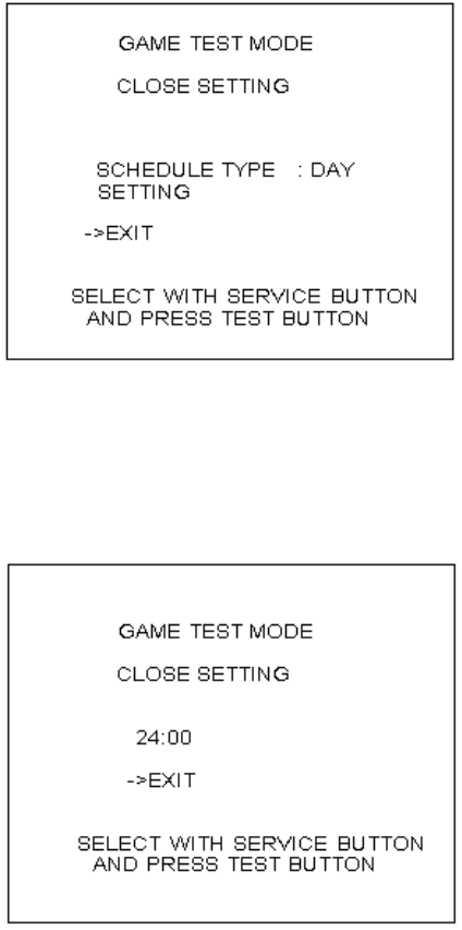
95
5.3.9. CLOSE SETTING
Select CLOSE SETTING to display the following screen.
Change the setting for the time when the store closes.
The game will be unusable for card play starting 15 minutes before the time you set until 6:00 AM the next
morning. Before the store closing time, be sure to pay attention to the players with the card.
You can set SCHEDULE TYPE to DAY, WEEK or OFF. Press the TEST Button to select the item. (The unit
is shipped with SCHEDULE TYPE set to OFF.)
Move the cursor to SETTING and press the TEST Button to display the appropriate time setting screen.
DAY: Set the daily store closing time. This time setting will be used every day
Set the daily store closing time. When you press the SERVICE Button, the "hour" display will begin to flash.
Press the TEST Button to select any hour from "19" to "26".
Press the SERVICE Button again to accept the "hour" selection. Once accepted, the "minute" display will
then begin to flash. Press the TEST Button to select one of the following "minute" options: "00, 15, 30, 45".
Press the SERVICE Button again to accept the "minute" selection.
When complete, move the cursor to EXIT. If you press the SERVICE Button when the cursor is next to
EXIT, the "hour" display will begin to flash again indicating that you can change the settings.
Move the cursor to EXIT and press the TEST Button to return to the CLOSE SETTING screen.
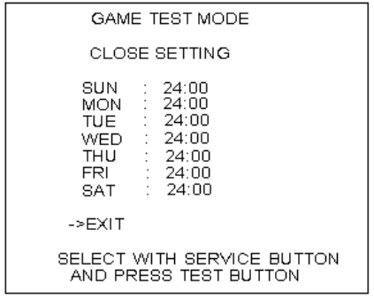
96
WEEK: Set a different store close time for each day of the week
Set the store closing time for each day of the week. When you press the SERVICE Button, the "hour"
display will begin to flash. Press the TEST Button to select any hour from "19" to "26".
Press the SERVICE Button again to accept the "hour" selection. Once accepted, the "minute" display will
then begin to flash. Press the TEST Button to select one of the following "minute" options: "00, 15, 30, 45".
Press the SERVICE Button again to accept the "minute" selection. Once accepted, the "hour" display for
the next day of the week will begin to flash. Set the "hour" and "minute" settings in the same fashion as
described above.
When you have completed setting the time for SAT, move the cursor to EXIT. If you press the SERVICE
Button when the cursor is next to EXIT, the "hour" display for SUN will begin to flash again indicating that
you can change the settings.
Move the cursor to EXIT and press the TEST Button to return to the CLOSE SETTING screen.
OFF: Do not set any store closing times. Other SETTING items are not displayed
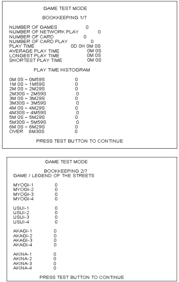
97
5.4. BOOKKEEPING
Select BOOKKEEPING to display the following screens of operating status data. Each time the
TEST Button is pressed, the ensuing page appears. Pressing the TEST Button while the 5/5 page is
displayed causes the Game Test Menu to return on the screen.
Press the TEST Button to move to screen 3/7 of BOOKKEEPING.
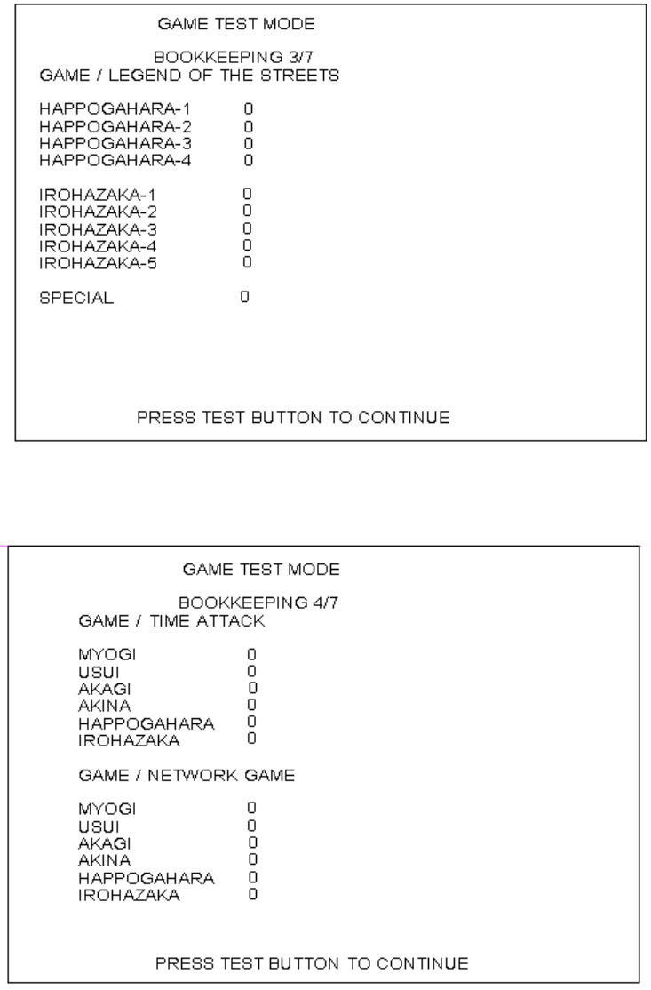
98
GAME/LEGEND OF THE STREETS: Displays the number of times each rival character was selected in
"Legend of the Street" mode. "MYOGI-1" refers to the first rival in MYOGI who is IGGY.
Press the TEST Button to move to screen 4/7 of BOOKKEEPING.
GAME/TIME ATTACK: Displays the number of times each course was selected in TIME ATTACK mode
GAME/NETWORK GAME: Displays the number of times each course was selected in NETWORK GAME
(VERSUS) mode
Press the TEST Button to move to screen 5/7 of BOOKKEEPING
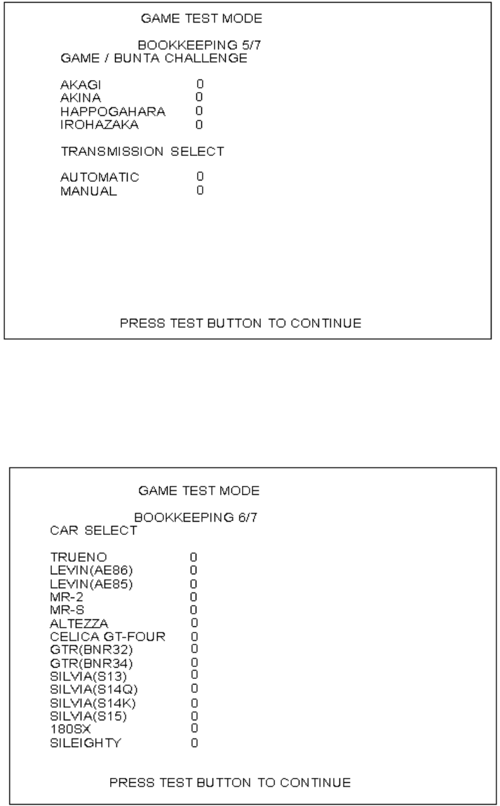
99
GAME/BUNTA CHALLENGE: Displays number of times each course has been selected for the Bunta
Challenge.
TRANSMISSION SELECT: Displays the number of times each TRANSMISSION was selected in all game
modes.
Press the TEST Button to move to screen 6/7 of BOOKKEEPING.
Press the TEST Button to move to screen 7/7 of BOOKKEEPING.
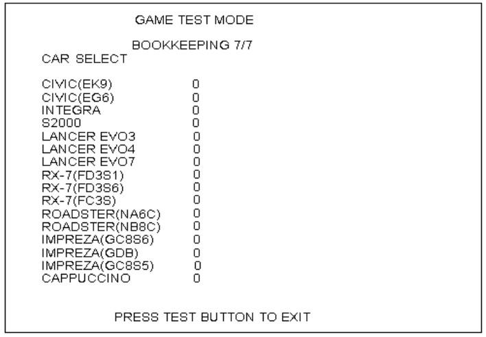
100
CAR SELECT: Displays the number of times each car was selected
Move the cursor to EXIT and press the TEST Button to return to the Game Test Menu screen.
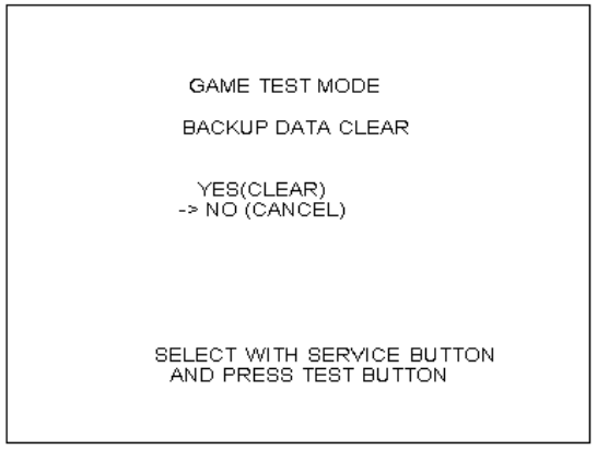
101
5.4.1. BACKUP DATA CLEAR
Delete all BOOKKEEPING screen data. Use BACKUP DATA CLEAR in the SYSTEM TEST MODE
to delete data about coin/credit collection.
Deleting this data does not affect the game settings or other data stored by the game.
Deleting this data will delete the data showing how many times the CARD R/W was used.
After deleting the data, the CARD R/W automatically enters Head Cleaning mode.
Refer to section <7-2> Head Cleaning for more information about head cleaning.
To clear data, use the SERVICE Button to move the cursor to YES (CLEAR) and then press the
TEST Button. When the data has been cleared, the message "COMPLETED" will be displayed.
Press the TEST Button again to return to the Game Test Menu screen.
Move the cursor to NO (CANCEL) and press the TEST Button to return to the Game Test Menu screen
without clearing the data.
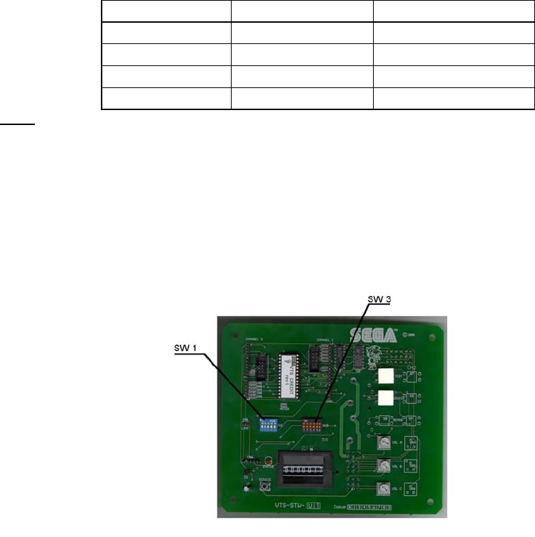
102
6. COIN MECH INSTALLATION AND CREDIT BOARD SET UP
6.1. INTRODUCTION
Game credits between the Coin Mechanism and the game board for this machine are controlled by a VTS
board. This electronic circuit allows the price of play to be set for a range of different countries. These
functions are set on Dual In Line (DIL) PCB mounted switches.
SW1 is used to set the currency (or coin ratio) and SW3 the price of play. Refer to the Tables on the
following pages for the correct settings for your environment.
The VTS board pictured below is mounted in the Coin Chute Tower.
The VTS board is connected to the coin validator and lamps via a dedicated wiring harness depending
upon the coin validator used:
Wiring Harness Validator
LM1006 Coin Controls (15 way connector)
LM1007 Mars (13 way connector)
LM1008 Mechanical See note 2
N/A NRI See note 1
Notes
1. If NRI mechanisms are to be used, these should be ordered with the highest denomination coin on coin
path #1 and the lowest denomination on coin path #4. The VTS board should be then be set up for
either the UK or Switzerland settings. A minimum connecting lead length of 600mm is required.
2. Mechanical coin mechanisms may be connected in parallel allowing two identical mechanisms to be
fitted.
The VTS Board
103
Credit Board Mode Settings Switch 3
Country Setting Switch 3 Setting Coin Validator Programming C120/SR3 Only
SW1 SW2 SW3 SW4 SW5 SW6 COIN1 COIN2 COIN3 COIN4 COIN5 COIN6 COIN7 COIN8 COIN9 COIN10 COIN11 COIN12
UK Coin Controls
C220 Parallel
OFF OFF OFF OFF £1 50p new 20p 10p - 50p old - -
UK Coin Controls
C220 Binary
ON OFF OFF OFF £1 50p new 20p 10p - 50p old - £2
UK Coin Controls
C220 Binary
OFF ON OFF OFF £1 50p new 20p 10p - £2 - 50p
old
UK Coin Controls
SR3 Parallel
ON ON OFF OFF £1 50p new 20p 10p - £2 - 50p
old
- - - -
UK
Euro
Coin Controls
SR3 Parallel
OFF OFF ON OFF £2
€2
£1
€1
50p new
50¢
20p
20¢
10p
10¢
- - - 50p old - - -
UK Mars ME/MS
111 Parallel
ON OFF ON OFF £1 £2 20p 10p 50p new 50p old
UK NRI Parallel OFF ON ON OFF 10p 20p 50p £1 £2 -
Belgium Parallel ON ON ON OFF - 50BFr 20BFr 5BFr
Holland Parallel OFF OFF OFF ON - 5NLG 2.5NLG 1NLG
Austria SR3 Parallel ON OFF OFF ON 20Sch 10Sch 5Sch 1Sch
Spain Coin Controls
C220 Binary
OFF ON OFF ON 500Pta 200Pta 100Pta 50Pta 25Pta 200Pt
old
50Pta old 25Pta old
Spain SR3/NRI
Parallel
ON ON OFF ON 500Pta 200Pta 100Pta 50Pta 25Pta - - 200Pta - 50Pta old 25Pta old -
Spain Coin Controls
C220 Parallel
OFF OFF ON ON 100Pta 50Pta
new
- 25Pta
new
- 50Pta
old
- 25Pta old
Portugal
Euro
Parallel ON OFF ON ON 200Es
€1
100Es
50¢
50Es - - - - -
TBA OFF TBA Please Note
The credit board automatically sets the validator for parallel and binary
operation through an output on pin 8 of the 17 way pinstrip. For the feature
to work it is necessary for the validator interconnecting cable to include at
wire at this position
ON TBA
Channels OFF Direct Mode
ON 2 channel Mode
Note: These switch settings are under constant review and may change due to world currency updates.
• Set SW 1 according to the option settings found in the relevant Price of Play Settings Table on the following pages.
• For Germany (DM), France (Fr) & Switzerland (SFr), use the appropriate existing setting shown above (from another country) that matches the coin ratios programmed into your coin mech.
• Set SW 3 on the VTS /Excel board as shown in the table above corresponding to the country required.

104
6.1.1. PRICE OF PLAY SETTINGS UK
Price Bonus DIL Switch 1
Switch 1 Switch 2 Switch 3 Switch 4 Switch 5
1 10p No Bonus OFF OFF OFF OFF OFF
2 10p 6 = 50p ON OFF OFF OFF OFF
3 20p No Bonus OFF ON OFF OFF OFF
4 20p 3 = 50p 6 = £1 12 =£2 ON ON
OFF OFF OFF
5 30p No Bonus OFF OFF ON OFF OFF
6 30p 1.66 = 50p 4 = £1 8 = £2 ON OFF ON OFF OFF
7 30p 2 = 50p 4 = £1 OFF ON ON OFF OFF
8 30p AMLD * 3 = £1 6 = £2 ON ON ON
OFF OFF
9 40p No Bonus OFF OFF OFF ON OFF
10 40p 1.25 = 50p 3 = £1 6 = £2 ON OFF OFF ON OFF
11 50p No Bonus OFF ON OFF ON OFF
12 50p 3 = £1 6 = £2 ON ON
OFF ON OFF
13 50p 2 = £1 5 = £2 OFF OFF ON ON OFF
14 60p No Bonus ON OFF ON ON OFF
15 60p 2 = £1 4 = £2 OFF ON ON ON OFF
16 80p No Bonus ON ON ON ON OFF
17 80p 1.25 = £1 2 = £1.50 2.5 = £2 OFF OFF OFF OFF ON
18 £1 No Bonus ON OFF OFF OFF ON
19 £1 3 = £2 OFF ON OFF OFF ON
20 £1 2 = £2 5 = £4 ON ON
OFF OFF ON
21 £1.50 No Bonus OFF OFF ON OFF ON
22 £1.50 2 = £2 ON OFF ON OFF ON
23 £2 No Bonus OFF ON ON OFF ON
24 £2 3 = £5 ON ON ON
OFF ON
25 £3 No Bonus OFF OFF OFF ON ON
26 £3 2 = £5 ON OFF OFF ON ON
27 £5 No Bonus OFF ON OFF ON ON
28 £5 3 = £10
ON ON
OFF ON ON
29 £7.50 No Bonus OFF OFF ON ON ON
30 £7.50 2 = £10 ON OFF ON ON ON
31 £10 No Bonus OFF ON ON ON ON
32 Free Play ON ON ON ON ON

105
6.1.2. PRICE OF PLAY SETTINGS EURO
Price Bonus DIL Switch 1
Switch 1 Switch 2 Switch 3 Switch 4 Switch 5
1 10¢ No Bonus OFF OFF OFF OFF OFF
2 10¢ 6 = 50¢ ON OFF OFF OFF OFF
3 20¢ No Bonus OFF ON OFF OFF OFF
4 20¢ 3 = 50¢ 6 = €1 12 =€2 ON ON
OFF OFF OFF
5 30¢ No Bonus OFF OFF ON OFF OFF
6 30¢ 1.66 = 50¢ 4 = €1 8 = €2 ON OFF ON OFF OFF
7 30¢ 2 = 50¢ 4 = €1 OFF ON ON OFF OFF
8 30¢ AMLD * 3 = €1 6 = €2 ON ON ON
OFF OFF
9 40¢ No Bonus OFF OFF OFF ON OFF
10 40¢ 1.25 = 50¢ 3 = €1 6 = €2 ON OFF OFF ON OFF
11 50¢ No Bonus OFF ON OFF ON OFF
12 50¢ 3 = €1 6 = €2 ON ON
OFF ON OFF
13 50¢ 2 = €1 5 = €2 OFF OFF ON ON OFF
14 60¢ No Bonus ON OFF ON ON OFF
15 60¢ 2 = €1 4 = €2 OFF ON ON ON OFF
16 80¢ No Bonus ON ON ON ON OFF
17 80¢ 1.25 = £1 2 = €1.50 2.5 = €2 OFF OFF OFF OFF ON
18 €1 No Bonus ON OFF OFF OFF ON
19 €1 3 = €2 OFF ON OFF OFF ON
20 €1 2 = €2 5 = €4 ON ON
OFF OFF ON
21 €1.50 No Bonus OFF OFF ON OFF ON
22 €1.50 2 = €2 ON OFF ON OFF ON
23 €2 No Bonus OFF ON ON OFF ON
24 €2 3 = €5 ON ON ON
OFF ON
25 €3 No Bonus OFF OFF OFF ON ON
26 €3 2 = €5 ON OFF OFF ON ON
27 €5 No Bonus OFF ON OFF ON ON
28 €5 3 = €10
ON ON
OFF ON ON
29 €7.50 No Bonus OFF OFF ON ON ON
30 €7.50 2 = €10 ON OFF ON ON ON
31 €10 No Bonus OFF ON ON ON ON
32 Free Play ON ON ON ON ON

106
6.1.3. PRICE OF PLAY SETTINGS Austria-Czech-Denmark-Norway-
Israel-France2
Price Bonus Switch 1
Switch 1 Switch 2 Switch 3 Switch 4 Switch 5
1 1 No Bonus OFF OFF OFF OFF OFF
2 1 11 = 10
ON OFF OFF OFF OFF
3 1 6 = 5 OFF ON OFF OFF OFF
4 2 No Bonus ON ON OFF OFF OFF
5 2 6 = 10 OFF OFF ON OFF OFF
6 2 3 = 5 ON OFF ON OFF OFF
7 3 No Bonus OFF
ON ON OFF OFF
8 3 4 = 10 ON ON ON OFF OFF
9 3 2 = 5 OFF OFF OFF ON OFF
10 4 No Bonus ON OFF OFF ON OFF
11 4 3 = 10 OFF ON OFF ON OFF
12 5 No Bonus ON ON OFF ON OFF
13 5 3 = 10 OFF OFF ON ON OFF
14 6 No Bonus ON OFF ON ON OFF
15 6 4 = 20 OFF ON ON ON OFF
16 8 No Bonus ON ON ON ON OFF
17 10 No Bonus OFF OFF OFF OFF ON
18 10 3 = 20 ON OFF OFF OFF ON
19 20 No Bonus OFF ON OFF OFF ON
20 20 3 = 50 ON ON OFF OFF ON
21 30 No Bonus OFF OFF ON OFF ON
22 30 2 = 50 ON OFF ON OFF ON
23 50 No Bonus OFF ON ON OFF ON
24 50 3 = 100
ON ON ON OFF ON
32 Free Play ON ON ON ON ON
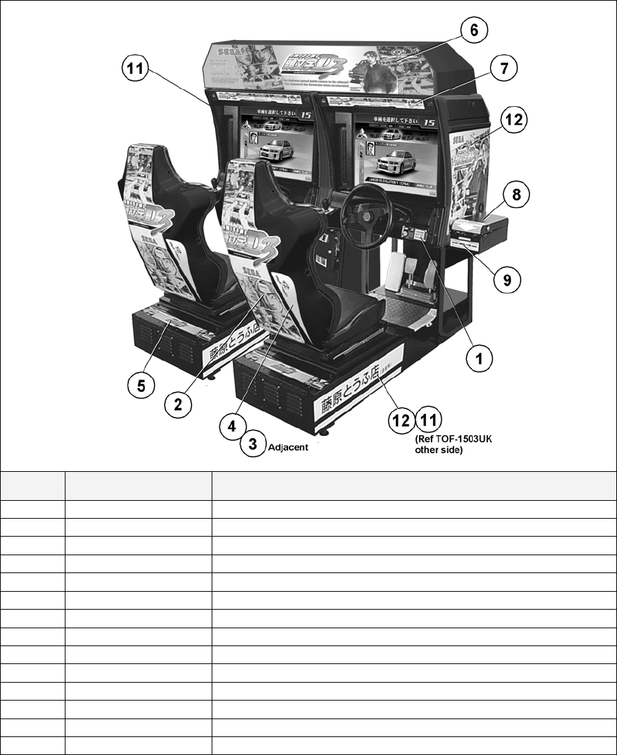
107
7. DESIGN RELATED PARTS
ITEM PART NO, DESCRIPTION
1 TOS-2152UK STICKER START/VIEW/CREDIT
2 TOS-1603-BUK STICKER SEAT BACK
3 TOS-1603-CUK STICKER SEAT BACK L
4 TOS-1603-DUK STICKER SEAT BACK R
5 TOS-1504UK STICKER BASE LID
6 TOS-0203UK BILLBOARD PLATE TOS TWIN
7 422-0924UK PLAY INSTR SH TOS MULTI
8 TOS-0004UK STICKER CARD SLOT TOF A MULTI
9 TOT-0005UK STICKER CARD SLOT TOF B MULTI
10 421-7987-TOT-T STICKER ELEC SPEC TOS TW
11 TOS-1551-AUK STICKER COVER PANEL L
12 TOS-1556-AUK STICKER COVER PANEL R
13 TOF-1502UK STICKER BASE L
14 TOF-1503UK STICKER BASE R
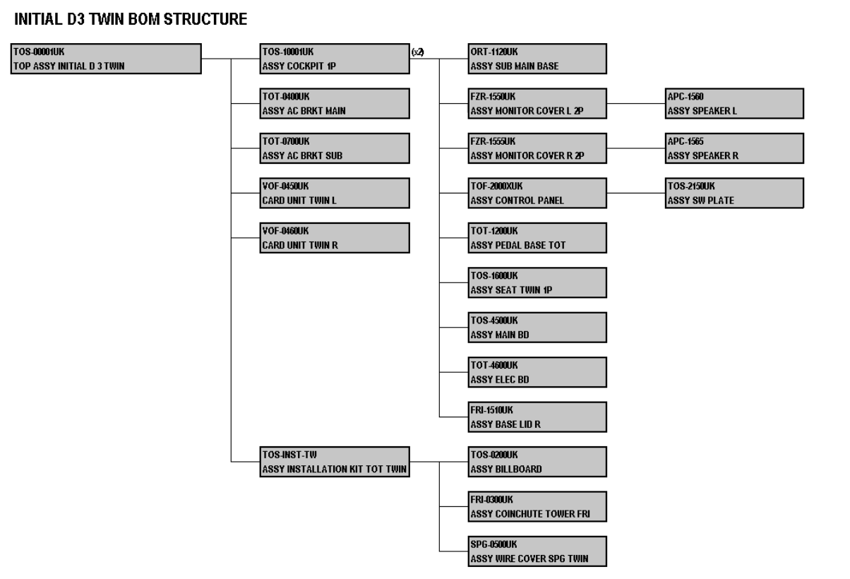
108
8. PARTS LIST
8.1. ASSEMBLY STRUCTURE
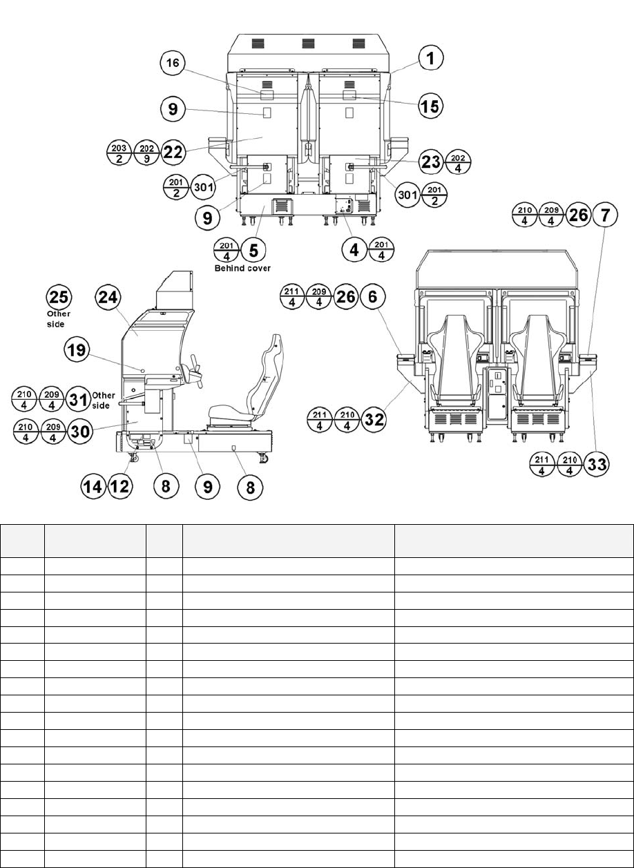
109
8.2. TOS-00001UK TOP ASSY INITIAL D 3 TWIN
ITEM PART NO. QTY DESCRIPTION COMPONENT REF.
1 TOS-10001UK 2 ASSY COCKPIT 1P
3 TOS-INST-TW 1
ASSY INSTALLATION KIT TOT TWIN
4 TOT-0400UK 1 ASSY AC BRKT MAIN
5 TOT-0700UK 1 ASSY AC BRKT SUB
6 VOF-0450UK 1 CARD UNIT TWIN L
7 VOF-0460UK 1 CARD UNIT TWIN R
8 421-7020UK 4 STICKER CAUTION FORK
9 LB1102 6 STICKER DANGEROUS VOLTAGE BACK LIDS-4, REAR FLOOR-2
12 421-7987-TOS-T 1 STICKER ELEC SPEC TOT TW MAIN CABI, LHS OF MAIN BASE
14 421-7988-91UK 3 STICKER SERIAL NUMBER UK 1P-1,2P-2,CCT INSIDE TOP DOOR
15 421-8543UK 1 STICKER CABINET L UK 1P
16 421-8544UK 1 STICKER CABINET R UK 2P
18 SGM-3863 2 POLY COVER 1800X950X1700
19 SDW-0001UK 24 BLIND CAP 1P CABI (LHS), 2P CABI (RHS)
22 INY-0004 2 BACK LID INY
23 CKT-0001UK 2 BACK LID B W/HOLE UK
24 TOS-1551-AUK 1 STICKER COVER PANEL L
25 TOS-1556-AUK 1 STICKER COVER PANEL R

110
ITEM PART NO. QTY DESCRIPTION COMPONENT REF.
26 CKT-0015UK 2 STICKER CARD LOADING INSTR
27 LB1046 1 LABEL TESTED FOR ELEC. SAFETY
28 RAL-XXXX-13UK 2 LOCK COVER UK (R.FLOORS)-2
30 CKT-0004 1 SIDE PNL L
31 CKT-0005 1 SIDE PNL R
32 CKT-0006 1 CARD UNIT BASE L
33 CKT-0007 1 CARD UNIT BASE R
201 000-P00412-WB 12 M4X12 MSCR PAN W/FS BLK (4)-4,(5)-4,(301)-4
202 000-P00408-WB 26 M4X8 MSCR PAN W/FS BLK (22)-18,(23)-8
203 010-P00412 4 M4X12 S-TITE PAN PAS (22)-4
204 008-T00408-0C 16 M4X8 TMP PRF TH CRM (28)-8,(F.FLOORS)-8
205 029-B00620-0B 4 M6X20 SKT BH BLK (R.FLOORS)-4
206 060-S00600-0B 4 M6 WSHR SPR BLK (R.FLOORS)-4
207 060-F00600-0B 4 M6 WSHR FORM A FLT BLK (R.FLOORS)-4
209 030-000820-SB 24 M8X20 BLT W/S BLK (6)-4, (7)-4, (30)-4, (31)-4, (32)-4, (33)-4
210 068-852216-0B 16 M8 WSHR 22OD FLT BLK (30)-4, (31)-4, (32)-4, (33)-4
211 060-F00800 8 M8 WSHR FORM A FLT PAS (6)-4, (7)-4
301 CKT-61009UK 2 WH EXT CARD R/W C
401 PK0359 2 SLEEVE COCKPIT TOS TWIN
402 PK0317 1 PALLET TOF
403 PK0359-LID 2 LID TOS TWIN
404 PK0341 1 PALLET TOT
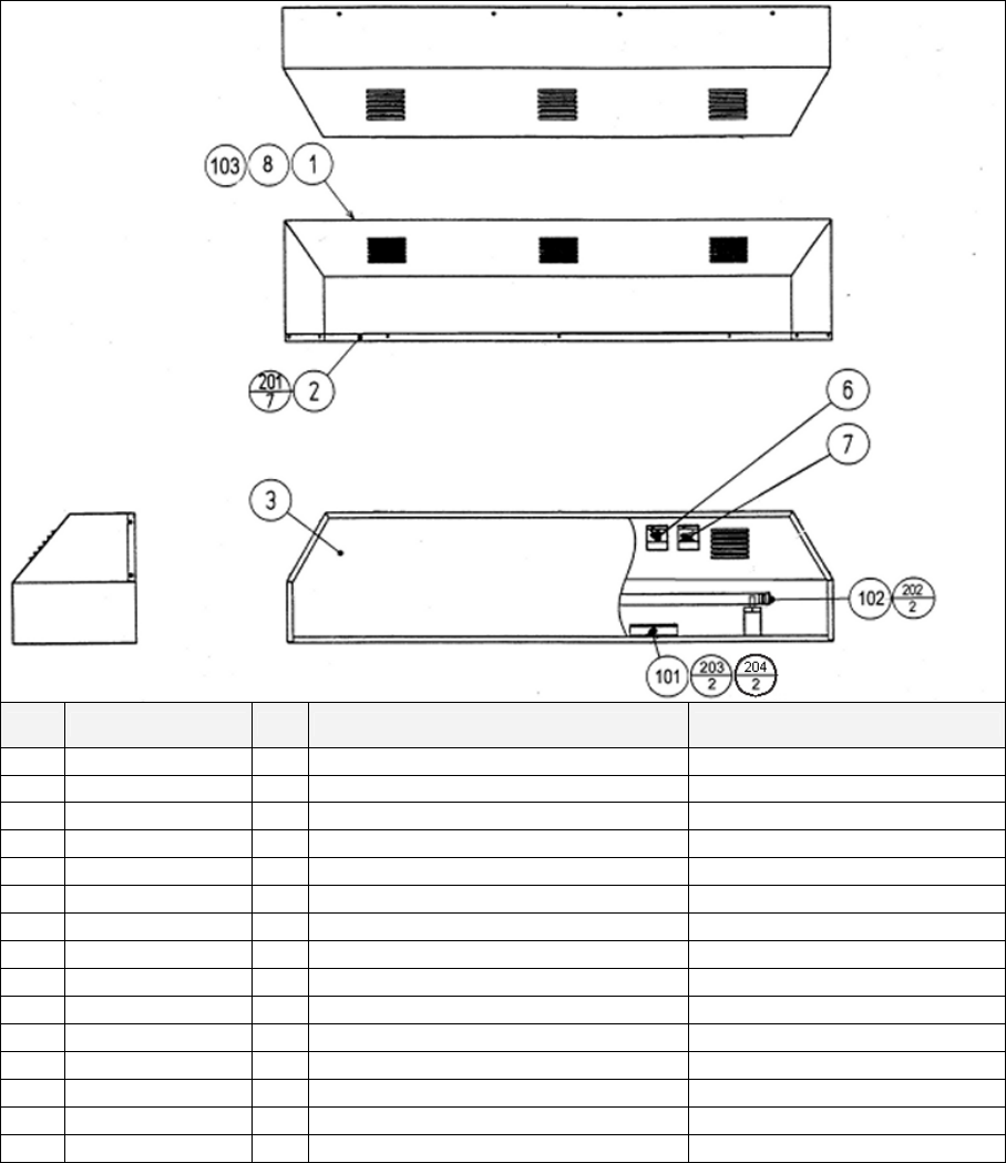
111
8.3. TOS-0200UK ASSY BILLBOARD
ITEM PART NO. QTY DESCRIPTION COMPONENT REF
1 POD-0201UK 1 BILLBOARD BOX BLACK/SHAPE
2 POD-0202UK 1 BILLBOARD SASH BLACK/SHAPE
3 TOS-0203UK 1 BILLBOARD PLATE TOT TWIN
6 LB1102 1 STICKER DANGEROUS VOLTAGE CENTRE BACK OF (1)
7 LB1104 1 STICKER CAUTION, HOT SURFACE CENTRE BACK OF (1)
8 LB1046 1 LABEL TESTED FOR ELEC. SAFETY
101 390-5695-40-CUK 1 FL TRAY 110V 40W (T12)
102 390-5695-40-BUK 1 FL TUBE 40W 4' DIA 1.5" T12
103 421-7501-10 1 STICKER FL 40W
201 000-T00408-0B 7 M4X8 MSCR TH BLK (2)-7
202 000-P00412 2 M4X12 MSCR PAN PAS TERRY CLIPS -2
203 068-441616 2 M4 WSHR 16OD FLT PAS (101)-2
204 050-F00400 3 M4 NUT FLG SER PAS (101)-2,(EARTH)-1
205 280-A00900-A 5 ROUTER TWIST D9 ADH
301 600-7064-031UK 1 WIRE HARN FL
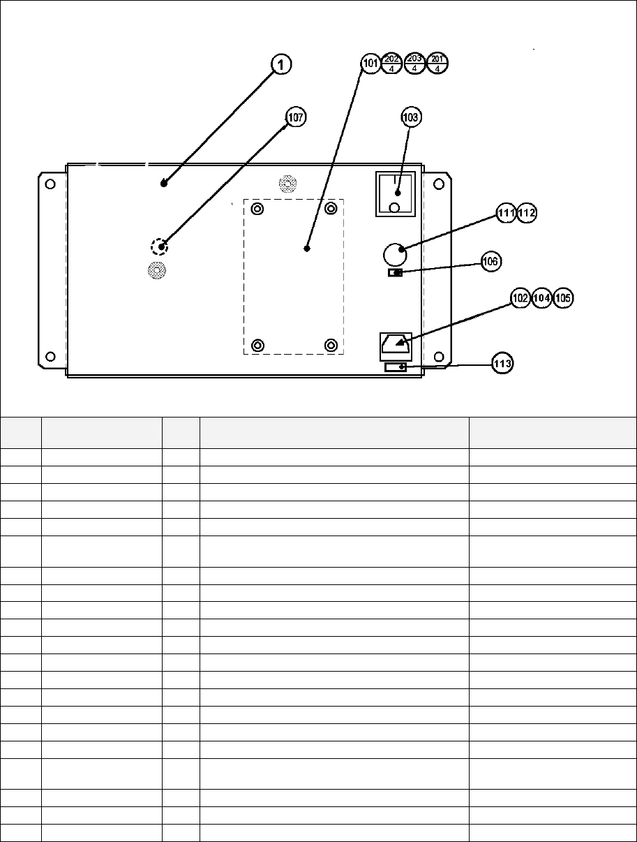
112
8.4. TOT-0400UK ASSY AC BRKT MAIN
ITEM PART NO. QTY DESCRIPTION COMPONENT REF.
1 TOF-0401UK 1 AC BRKT UK
101 EP1379 1 FILTER EMI 10A ARCOTRONICS
102 EP1302 1 EUROSOCKET FUSED 1OA 250Vac
103 EP1303 1 SWITCH ROCKER DPST 10A 250Vac
104 514-5078-10000 1 FUSE 5X20 CERAMIC SB 10000mA IEC INLET
105 310-5029-D508 5 HEAT SHRINK SLEEVING 50.8DIA OVER ITEM 102(50MM
OVER SOCKET)
106 421-6595-5000-T 1 STICKER FUSE 5000mA TYPE T FUSE HOLDER
107 LB1096 1 STICKER PROTECTIVE EARTH EARTH POINT INSIDE
108 211-5479-01 2 CONN OPT JOINT PNL-TOCA150
109 LB1087 1 STICKER FIBRE CABLE RX @ TOP
110 LB1088 1 STICKER FIBRE CABLE TX @ BOTTOM
111 EP1334 1 FUSE HOLDER 20mm 10A 240Vac
112 514-5078-5000 1 FUSE 5X20 CERAMIC SB 5000mA
113 421-6595-10000T 1 STICKER FUSE 10000mA TYPE T IEC INLET
201 060-S00300 4 M3 WSHR SPR PAS (101)-4
202 060-F00300 4 M3 WSHR FORM A FLT PAS (101)-4
203 000-P00310 8 M3X10 MSCR PAN PAS (101)-4,(108)-4
204 050-F00400 3 M4 NUT FLG SER PAS (INSIDE EARTH)-
2,(OUTSIDE)-1
301 600-6873-001UK 1 WIRE HARN XFMR IN
303 600-9030-44K 1 WIRE HARN EARTH 300mm M4/M4 K AC BRKT TO MAIN BASE
304 600-9040-45K 1 WIRE HARN EARTH 400mm M4/M5 K AC BRKT - XFMR
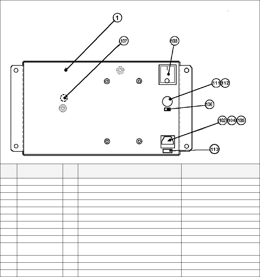
113
8.5. TOT-0700UK ASSY AC BRKT SUB
ITEM PART NO. QTY DESCRIPTION COMPONENT REFERENCE
1 TOF-0401UK 1 AC BRKT UK
106 421-6595-5000-T 1 STICKER FUSE 5000mA TYPE T FUSE HOLDER
107 LB1096 1 STICKER PROTECTIVE EARTH EARTH POINT INSIDE
108 211-5479-01 2 CONN OPT JOINT PNL-TOCA150
109 LB1087 1 STICKER FIBRE CABLE RX @ TOP
110 LB1088 1 STICKER FIBRE CABLE TX @ BOTTOM
111 EP1334 1 FUSE HOLDER 20mm 10A 240Vac
112 514-5078-5000 1 FUSE 5X20 CERAMIC SB 5000mA
203 000-P00310 4 M3X10 MSCR PAN PAS (108)-4
204 050-F00400 3 M4 NUT FLG SER PAS (INSIDE EARTH)-
2,(OUTSIDE)-1
303 600-9030-44K 1 WIRE HARN EARTH 300mm M4/M4 K AC BRKT TO MAIN BASE
304 600-9040-45K 1 WIRE HARN EARTH 400mm M4/M5 K AC BRKT - XFMR
305 600-6999-201UK 1 WIRE HARN SUB AC BRKT
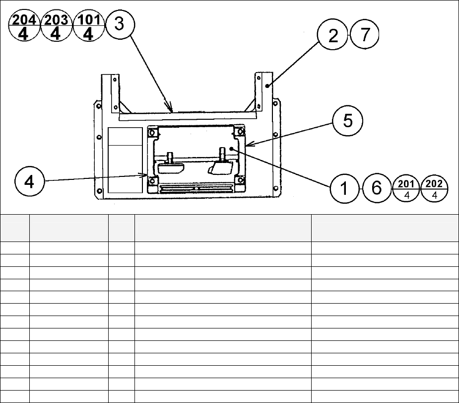
114
8.6. TOT-1200UK ASSY PEDAL BASE TOT
ITEM PART NO. QTY DESCRIPTION COMPONENT REF.
1 SPG-2200 1 ASSY BRAKE & ACCELL
2 TOF-1501UK 1 PEDAL BASE
3 NCR-1104UK 1 WIRE COVER BOX
4 SPG-2222UK 1 ANTI FINGER TRAP PLATE LEFT
5 SPG-2223UK 1 ANTI FINGER TRAP PLATE RIGHT
6 SPG-2224UK 1 PEDAL GASKET
7 SRT-2031UK 0.52 NEOPRENE RUBBER STRIP 10 (2)-520mm X1 INSIDE FLANGE
101 280-A01200-A 6 ROUTER TWIST D12 ADH WIRE COVER BOX
201 068-852216-0B 4 M8 WSHR 22OD FLT BLK (1)-4
202 030-000820-SB 4 M8X20 BLT W/S BLK (1)-4
203 000-P00408-WB 4 M4X8 MSCR PAN W/FS BLK (3)-4
204 050-F00400 3 M4 NUT FLG SER PAS (3)-3 EARTHS
301 600-9050-44K 1 WIRE HARN EARTH 500mm M4/M4 K WIRE COVER TO MAIN BASE
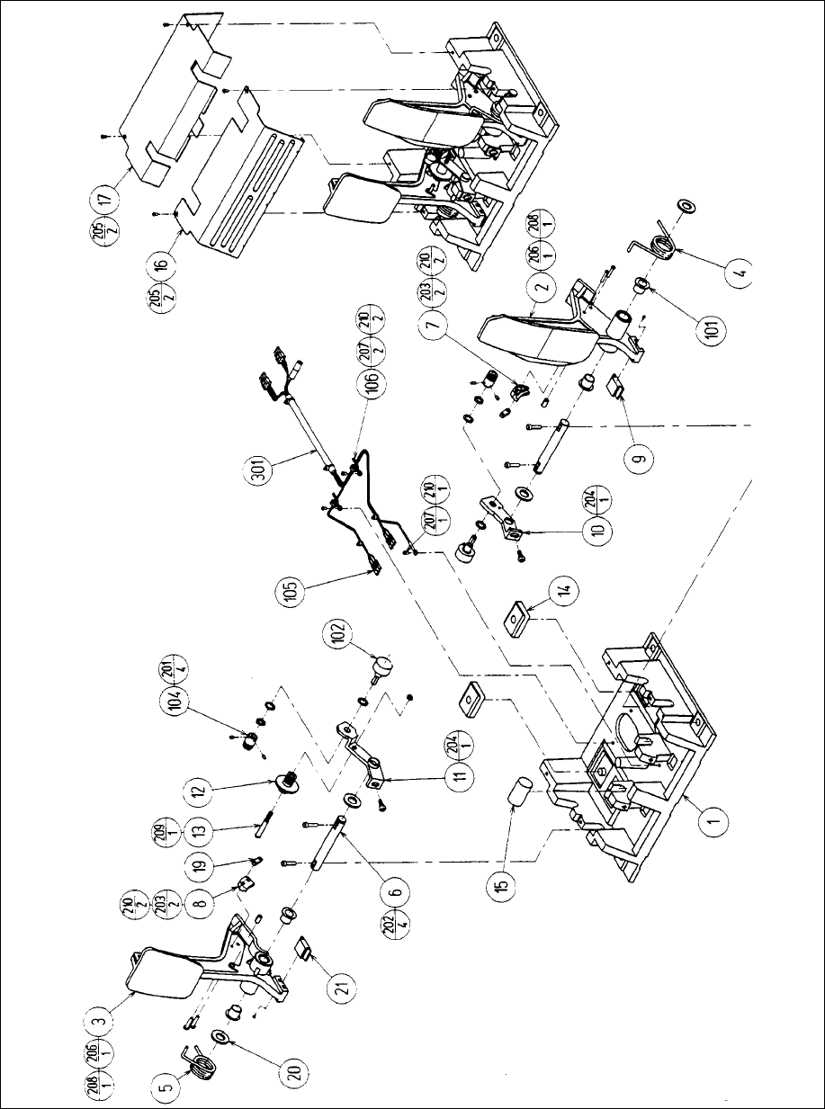
115
8.7. ASSY ACCEL & BRAKE (SPG2200)

116
Item Component Part Description Component Reference Qty
1 SPG-2201 BASE 1
2 SPG-2202 ACCEL PEDAL 1
3 SPG-2203 BRAKE PEDAL 1
4 SPG-2204 ACCEL SPRING 1
5 SPG-2205 BRAKE SPRING 1
6 SPG-2206 SHAFT 2
7 SPG-2207 ACCEL 1
8 SPG-2208 BRAKE GEAR 1
9 SPG-2209 NEUTRAL STOPPER 1
10 SPG-2210 VR PLATE ACCEL 1
11 SPG-2211 VR PLATE BRAKE 1
12 SPG-2212 AMPL GEAR 1
13 SPG-2213 GEAR SHAFT 1
14 SPG-2214 STOPPER 2
15 SPG-2215 RUBBER CUSHION 1
16 SPG-2216 COVER 1
17 SPG-2217 VR COVER 1
19 SPG-2219 GEAR STAY 2
20 SPG-2220 WSHR 4
21 SPG-2221 NEUTRAL STOPPR D 1
101 100-5263 BEARING 12 (OILES 80F-1212) 4
102 220-5484 VOL CONT B-5K OHM 2
104 601-7944 GEAR 15 2
105 310-5029-F15 SUNITUBE F F15MM 6
106 280-0419 HARNESS LUG 2
201 028-A00304-P SET SCR HEX SKT CUP P M3X4 4
202 020-000516-OZ HEX SKT H CAP SCR BLK OZ M5X16 4
203 000-P00420 M SCR PH M4X20 4
204 000-P00508-W M SCR PH W/FS M5X8 2
205 000-T00408-OC M SCR TH CRM M4X8 4
206 FAS-450005 SPR PIN BLK OZ 6X10 2
207 000-P00405 M SCR PH M4X5 3
208 FAS-000001 M SCR TH CRM M3X6 2
209 050-H00500 HEX NUT M5 1
210 060-F00400 FLT WSHR M4 7
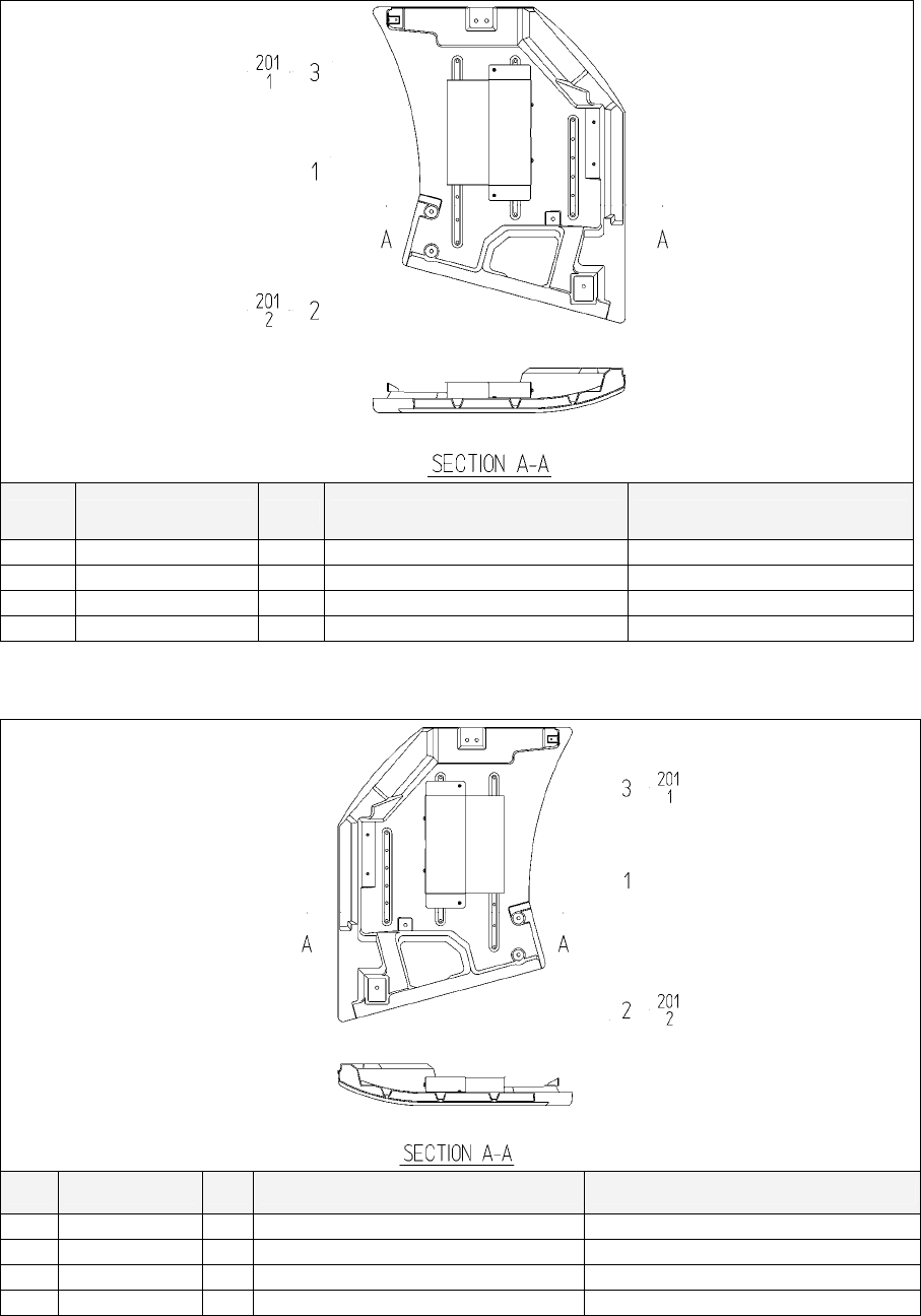
117
8.8. FZR-1550UK ASSY MONITOR COVER L 2P
ITEM PART NO. QTY DESCRIPTION COMPONENT REF.
1 POD-1161X-A 1 COVER PANEL L BLANK
2 APC-1560 1 ASSY SPEAKER L
3 DYN-1032UK 1 MASK BRKT
201 000-P00408-W 3 M SCR PH W/FS M4X8 (2)-2,(3)-1
8.9. FZR-1555UK ASSY MONITOR COVER R 2P
ITEM PART NO. QTY DESCRIPTION COMPONENT REF.
1 POD-1161X-A 1 COVER PANEL R BLANK
2 APC-1565 1 ASSY SPEAKER R
3 DYN-1032UK 1 MASK BRKT
201 000-P00408-W 3 M SCR PH W/FS M4X8 (2)-2,(3)-1
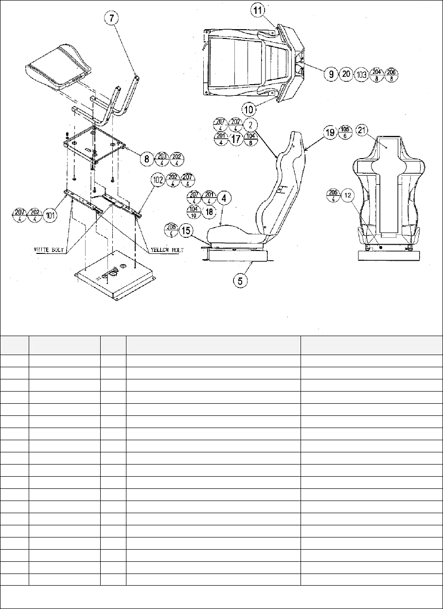
118
8.10. TOS-1600UK ASSY SEAT TWIN 1P
ITEM PART NO. QTY DESCRIPTION COMPONENT REF.
2 SPG-2401-A 1 UPPER SEAT BLANK
4 SPG-2402-A 1 LOWER SEAT BLANK
5 STC-1603 1 SEAT BASE
7 STC-1604 2 SEAT FRAME
8 STC-1606 1 SEAT MOUNT TRAY
9 STC-1607 2 SP MOUNT BRKT
10 STC-1608 1 SPEAKER NET L
11 STC-1609 1 SPEAKER NET R
12 STC-1610 1 SAFETY GUARD
14 STC-1612 2 PROTECT RUBBER
15 STC-1613 1 SAFETY GUARD F
16 OS1004 0.8 DRAFT EXCLDR 4 X7MM BLK x 10M (103)-0.8M
17 SPG-2401-BUK 1 UPPER SEAT INSERT (2)-1
18 SPG-2402-BUK 1 LOWER SEAT INSERT (4)-1
19 TOS-1603-AUK 1 SEAT REAR COVER BLANK UK
20 SRT-2409 2 SHOULDER PAD INBETWEEN SPKR NETS & SEAT
21 TOS-1603-BUK 1 STICKER SEAT BACK
22 TOS-1603-CUK 1 STICKER SEAT BACK L
23 TOS-1603-DUK 1 STICKER SEAT BACK R
Continued next page

119
Continued from previous page
ITEM PART NO. QTY DESCRIPTION COMPONENT REF.
101 601-9059-91 1 SEAT RAIL L
102 601-9060-91 1 SEAT RAIL R
103 130-5186-91 2 DUMMY SPEAKER
104 280-K02529-WX 18 DRIVE FASTENER 25FH 24L 7.9DIA (17)-8,(18)-10
105 280-5297 6 SCRIVET 8 1K31 (19)-6
201 030-000850-S 8 M8X50 BLT W/S PAS (2)-4,(4)-4
202 068-852216 20 M8 WSHR 22OD FLT PAS (2,4,8,101,102)-4EA
203 030-000816-S 4 M8X16 BLT W/S PAS (8)-4
204 000-P00410-W 8 M4X10 MSCR PAN W/FS PAS (9)-8
205 000-T00408-0B 8 M4X8 MSCR TH BLK (12)-4,(15)-4
206 012-P03512-F 8 N6X1/2" S/TAP FLG PAS (103)-8
207 050-U00800 8 M8 NUT NYLOK PAS (101)-4,(102)-4
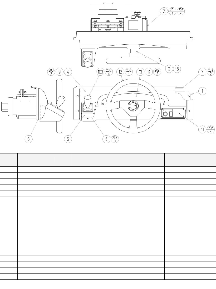
120
8.11. TOF-2000XUK ASSY CONTROL PANEL
ITEM PART NO. QTY DESCRIPTION COMPONENT REF.
1 TOF-2001UK 1 CONTROL PANEL BRKT
2 TOF-2500 1 ASSY HANDLE MECHA
3 TOS-2002UK 1 HANDLE COLLAR
4 TOF-2003 1 CONTROL PANEL COVER
5 TOF-2004 1 SHIFT COVER UPPER
6 TOF-2005 1 SHIFT COVER LOWER
7 TOF-2006UK 1 COVER HOLDER
8 OS1220 0.075 FOAM STRIP 8mmSQ ADHESIVE
9 TOF-2008UK 1 CTRL PNL PLATE (4)-1
11 TOT-2150UK 1 ASSY SW PLATE
12 601-11097 1 STEERING WHEEL 340
13 601-11098 1 STEERING EMBLEM 340
14 TOF-2010 1 STICKER STEERING EMBLEM (13)-1
15 TOS-2011UK 1 TAPER COLLAR
16 440-WS00220UK 1 WARNING STICKER TRAP HAZARD
102 280-A02000-A 5 ROUTER TWIST D20 ADH
103 610-0408-91 1 UP/DOWN SHIFTER AL
104 601-0460 1 CABLE TIE 100mm
105 280-A00900-A 3 ROUTER TWIST D9 ADH
Continued on next page

121
Continued from previous page
ITEM PART NO. QTY DESCRIPTION COMPONENT REF.
201 030-000820-S 4 M8X20 BLT W/S PAS (2)-4
202 060-F00800 4 M8 WSHR FORM A FLT PAS (2)-4
203 000-T00408-0B 5 M4X8 MSCR TH BLK (9)-2,(6)-3
204 000-P00410-W 2 M4X10 MSCR PH W/FS (7)-2
205 008-T00512-0B 4 M5X12 TMP PRF TH BLK (103)-4
206 000-T00410-0C 4 M4X10 TH CRM M4X10 (11)-4
207 000-T00408-0B 5 M4X8 MSCR TH BLK (102)-5
208 050-F01200 1 M12 NUT FLG SER PAS (12)-1
209 FAS-290015 3 M4X12 HEX SKT SCR FH BLK (13)-3
210 060-S01200 1 M12 WSHR SPR PAS (12)-1
301 TOF-60016UK 1 WH EXT VOLUME C
302 TOF-60017UK 1 WH EXT VIEW BUTTON C
303 TOF-60018UK 1 WH EXT SHIFTER
304 CKT-62037UK 1 WIRE HARN ENCODER EXT 2
305 CKT-62036UK 1 WIRE HARN SERVO OUTPUT EXT 2
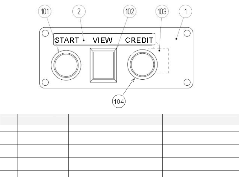
122
8.12. TOS-2150UK ASSY SW PLATE
ITEM PART NO. QTY DESCRIPTION COMPONENT REF.
1 TOS-2151UK 1 BUTTON PLATE
2 TOS-2152UK 1 STICKER START/VIEW/CREDIT
101 509-5838-Y 1 SW PB LW1L-15Y-TK1670 START
102 509-5495-05 1 PUSH BUTTON BLUE VIEW
103 280-A02000-A 1 ROUTER TWIST D20 ADH
104 509-5440 1 PUSH BTN SW IT GRN W/L DC14V CREDIT
301 TOF-60019UK 1 WH VIEW BUTTON
302 TOT-61078UK 1 WH PLAYER SELECT SW
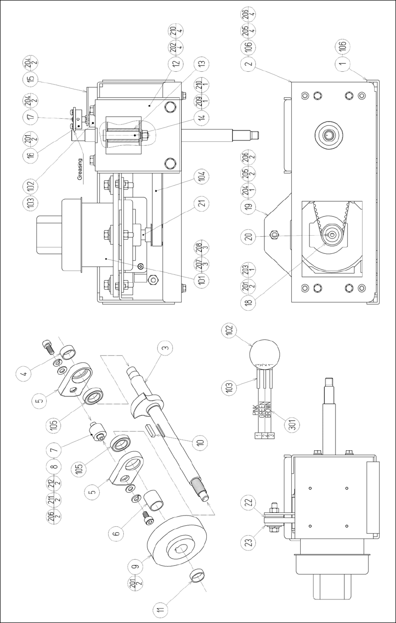
123
8.13. TOF-2500 ASSY HANDLE MECHA

124
ITEM PART NO. DESCRIPTION
1 TOF-2501 MECHA BASE
2 TOF-2502 MECHA BASE LID
3 TOF-2503 HANDLE SHAFT
4 TOF-2504 SPACER COLLAR A
5 TOF-2505 STOPPER BLOCK A
6 TOF-2507 SPACER COLLAR B
7 TOF-2508 STOPPER PIN SS
8 TOF-2509X STOPPER RUBBER SS
9 SPG-2505 PULLEY 60 S5M
10 DYN-1270 STOPPER KEY
11 TOF-2510 SPACER COLLAR C
12 TOF-2511 STOPPER HOLDER
13 TOF-2512 STOPPER RUBBER
14 TOF-2513 STOPPER BOLT
15 TOF-2514 VR BRKT
16 TOF-2515 GEAR HOLDER
17 601-6172 GEAR 48
18 SPG-2504 PULLEY 20 S5M
19 SPG-2506 MOTOR BRKT
20 SPG-2453 KEY 4 x 4 x 40
21 SPG-2454 MOTOR SHAFT COLLAR
22 ASK-3502 MOTOR SPACER
23 ASK-3503 MOTOR COLLAR
101 350-5448-01 SERVO MOTOR 500W NEW
102 220-5484 VOL CONT B-5K OHM
220-5753 VOL CONT B-5K OHM
103 310-5029-F20 SUMITUBE F F 20MM
104 601-11089 TIMING BELT (150 S5M 520)
105 100-5168 BEARING 20 (NSK 6904ZZ)
106 100-5285 BEARING 20 (6804ZZ)
201 028-A00408-P SET SCR HEX SKT CUP P M4 x 8
202 030-000820-S HEX BLT W/S M8 x 20
203 065-S012S0-Z STP RING BLK OZ S12
204 000-P00410-W M SCR PH W/FS M4 x 10
205 030-000612-S HEX BLT W/S M6x 12
206 060-F00600 FLT WSHR M6
207 030-000840-S HEX BLT W/S M8 x 40
208 068-852216 FLT WSHR 8.5-22 x 1.6
209 050-U00800 U NUT M8
210 060-F00800 FLT WSHR M8
211 020-000612-0Z HEX SKT H CAP SCR BLK 0Z M6 x 12
212 060-S00600 SPR WSHR M6
301 600-6866 WIRE HARN ASSY HANDLE MECHA VR
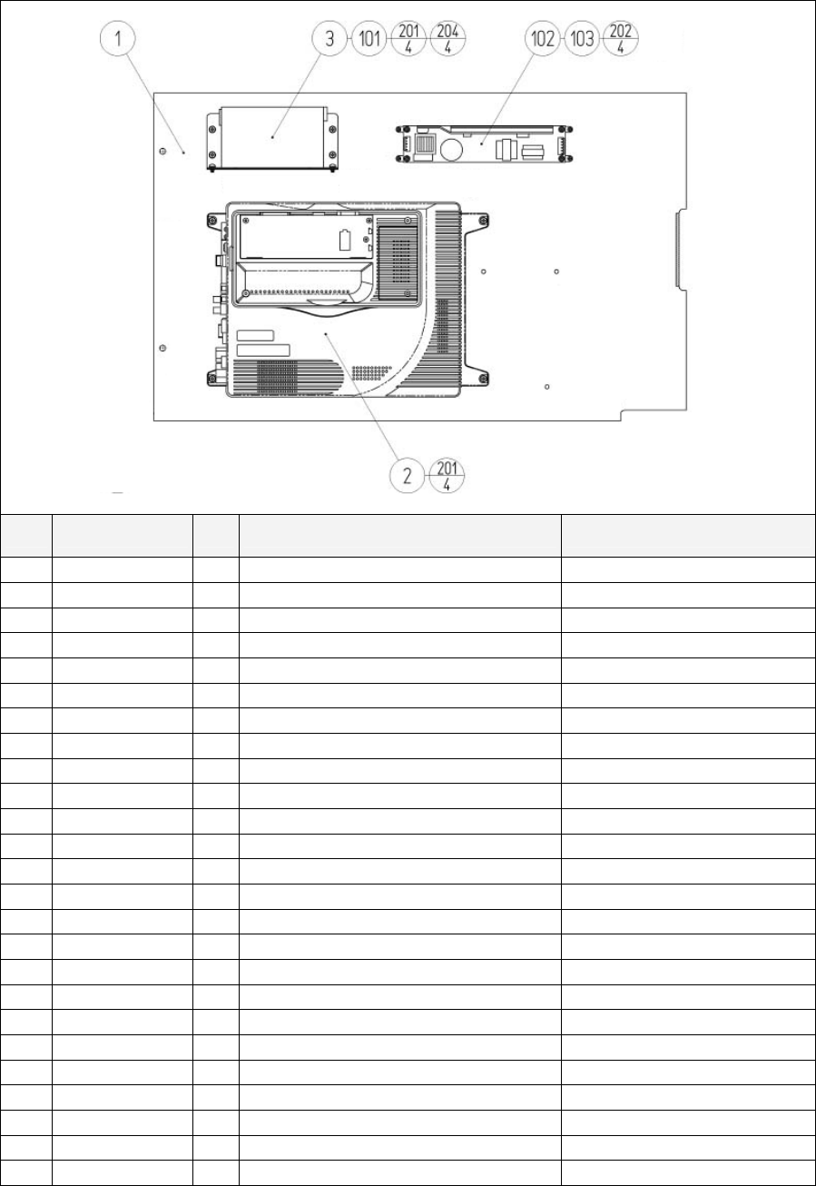
125
8.14. TOS-4500UK ASSY MAIN BD
ITEM PART NO. QTY DESCRIPTION COMPONENT REF.
1 TOF-4501UK 1 MAIN BD BASE
2 840-0091D-12 1 ASSY CASE NAT RT/232C &COM EXP
3 APC-4002 1 SW REG BRKT
4 105-5435 1 GD DRIVE BRKT STD
5 LB1111 1 STICKER PLEASE RECYCLE
6 610-0617 1 GD-ROM DRIVE UNIT NAOMI
7 610-0624-0033 1 GD SOFT KIT TOS ENG
8 253-5508-0384 1 KEY CHIP
101 400-5397-01 1 SW REGU FOR JVS VA
102 400-5421-07512 1 SW REGU LCA75S-12
103 OS1071 1 FEET P.C.B PKT OF 4 (102)-4 FEET
104 354081 4 TWIST LOK BHKL-450-4
105 354083 4 (A)TWIST N LOK BHKL-750-4
106 280-A00964-WX 6 ROUTER TWIST D09 SO6.4 WOOD X
107 LB1101 1 STICKER WARNING BATTERY GAME BD
201 000-P00416-W 11 M4X16 MSCR PAN W/FS PAS (2)-4,(4)-3,(3)-4
202 012-P03516 4 N6X5/8" S/TAP PAN PAS (102)-4
203 012-P00410-F 4 N8X3/8" S/TAP FLG PAS (6)-4
204 000-P00408-W 4 M4X8 MSCR PAN W/FS PAS (101)-4
302 TOF-60002UK 1 WH MAIN BD AC
303 TOF-60003UK 1 WH JVS PWR 6P W/CARD
304 TOF-60004UK 1 WH JVS PWR 8P W/GD
305 TOF-60005UK 1 WH MAIN BD I/O PWR
306 TOF-60006UK 1 WH MAIN BD SOUND
307 600-7247-500 1 CABLE SCSI ST-L TYPE2 500MM
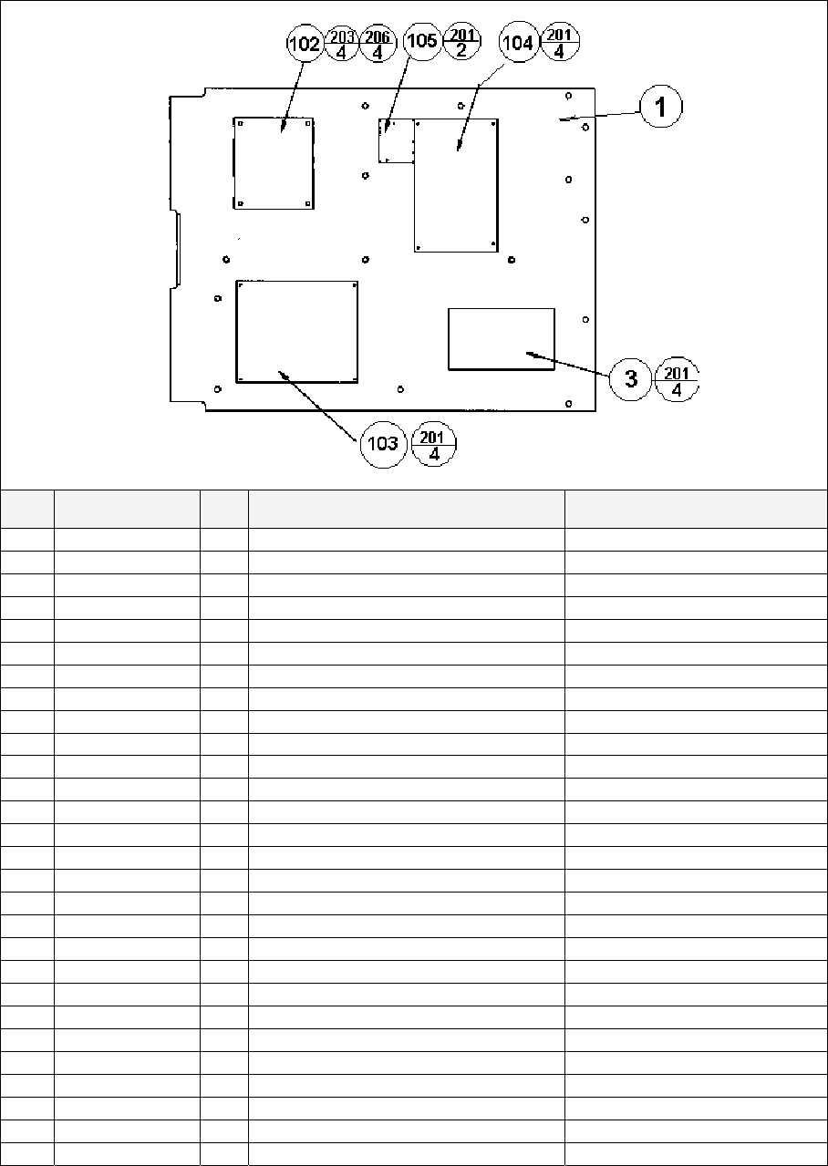
126
8.15. TOT-4600UK ASSY ELEC BD
ITEM PART NO. QTY DESCRIPTION COMPONENT REF.
1 TOF-4601UK 1 WOODEN BASE ELEC
3 837-13551-92 1 I/O CONTROL BD FOR JVS
102 560-5394UK 1 TRANSFORMER DUT TW
103 838-13578 1 PWR AMP 2CH & MIXER
104 838-14174 1 SERVO MOTOR DRIVE BD MIDI
105 838-11856CE-02 1 CONNECT BD W/FUSE 6.3A CE
107 354081 11 TWIST LOK BHKL-450-4
108 354083 10 (A)TWIST N LOK BHKL-750-4
109 280-A00964-WX 12 ROUTER TWIST D09 SO6.4 WOOD X
201 012-P00325 14 N4X1" S/TAP PAN PAS (3)-4,(103)-4,(104)-4,(105)-2
203 000-P00416-W 4 M4X16 MSCR PH W/FS (102)-4
206 068-441616 4 M4 WSHR 16OD FLT PAS (102)-4
301 600-7141-100 1 CABLE JVS TYPE A-B 100CM
302 600-6985-006UK 1 WIRE HARN 100V OUT
303 FRI-61003UK 1 WIRE HARN CONN BD B
306 TOF-60104UK 1 PWR AMP 14V AC IN
307 NCR-61002UK 1 WH AMP VR
308 NCR-61003UK 1 WH AMP AUDIO
309 NCR-61004UK 1 WH AMP SP F
310 TOF-60001UK 1 WH CONN BD OUT A
311 TOF-60007UK 1 WH MIDI
312 TOF-60008UK 1 WH ELEC BD I/O PWR
313 TOF-60009UK 1 WH I/O BD
314 TOF-60105UK 1 WH I/O BRD A/D
315 POD-61057UK 1 WH EARTH AC UNIT
316 FRI-61030UK 1 WIRE HARN EXT MOTOR A
317 TOF-60011UK 1 WH EXT ENCODER A
318 440036 1 FERRITE 74271221
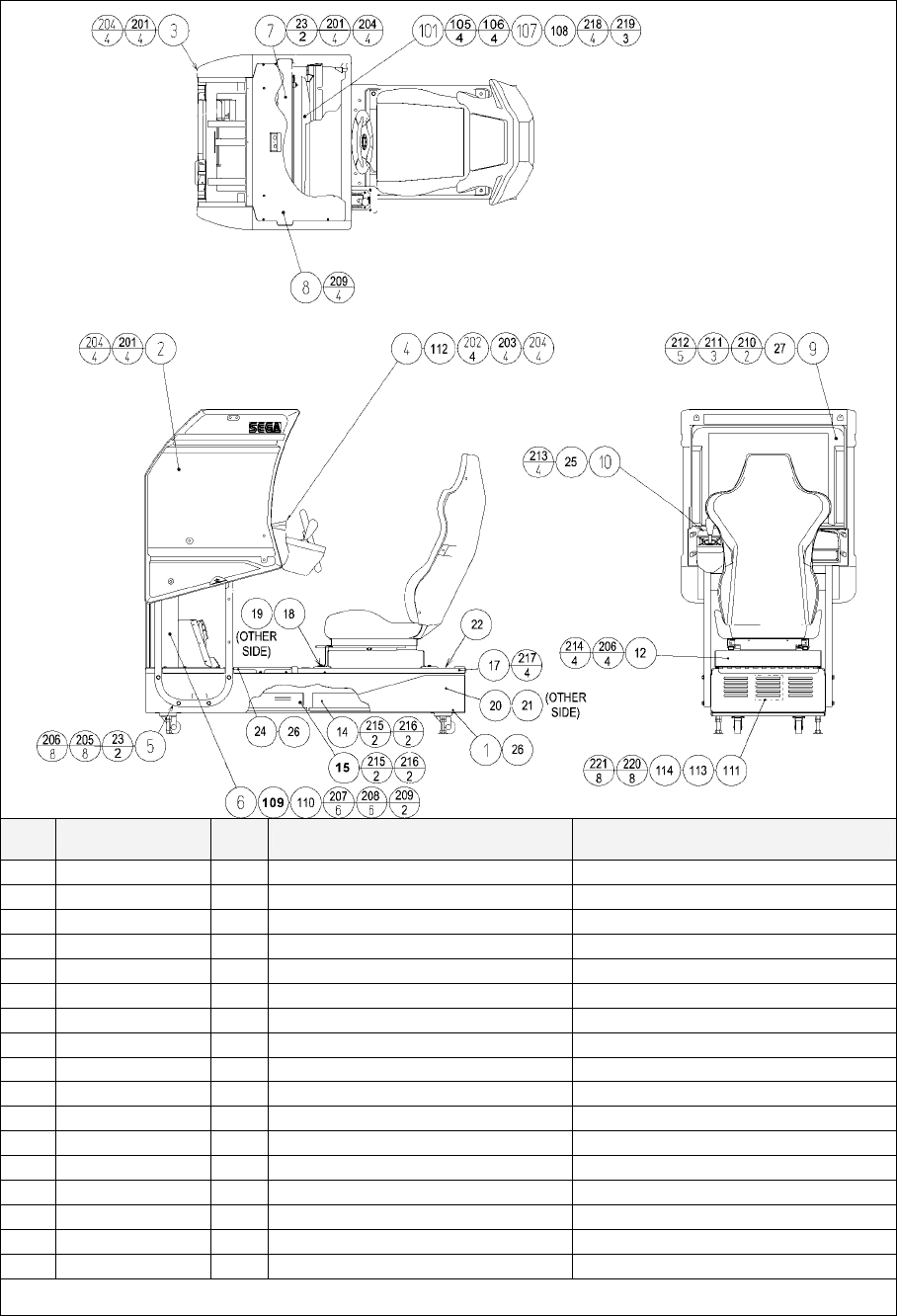
127
8.16. TOS-10001UK ASSY COCKPIT 1P
ITEM PART NO. QTY DESCRIPTION COMPONENT REF.
1 ORT-1120UK 1 ASSY SUB MAIN BASE
2 FZR-1550UK 1 ASSY MONITOR COVER L 2P
3 FZR-1555UK 1 ASSY MONITOR COVER R 2P
4 TOF-2000XUK 1 ASSY CONTROL PANEL
5 POD-1023UK 1 MONITOR STAND
6 TOT-1200UK 1 ASSY PEDAL BASE TOT
7 POD-1021UK 1 MONITOR SUPPORT
8 DUT-1008UK 1 ROOF LID DUT
9 POD-1022 1 MONITOR MASK
10 SPG-1005 1 MASK HOLDER
12 TOS-1600UK 1 ASSY SEAT TWIN 1P
14 TOS-4500UK 1 ASSY MAIN BD
15 TOT-4600UK 1 ASSY ELEC BD
17 FRI-1510UK 1 ASSY BASE LID R
18 RAL-2007 1 RUBBER HOLDER R TWIN (12)-1
19 RAL-2008 1 RUBBER HOLDER L TWIN (12)-1
20 TOF-1502UK 1 STICKER BASE L
Continued on next page

128
Continued from previous page
ITEM PART NO. QTY DESCRIPTION COMPONENT REF.
21 TOF-1503UK 1 STICKER BASE R
22 TOS-1504UK 1 STICKER BASE LID (17)-1
23 POD-1026UK 4 CRT SPACER (POD) (5)-2,(7)-2
24 DUT-2031UK 1 FRONT FLOOR UK DUT FIX DOWN AT NEXT LEVEL UP
25 SRT-1009UK 1 MONITOR SPASHGUARD SRT TW FIX TO (10)
26 SRT-2031UK 0.9 NEOPRENE RUBBER STRIP 10X3mm (24)-0.5,(1)-0.4 4X10cm STRIPS
27 OS1004 0.705 DRAFT EXCLDR 4 X7MM BLK x 10M (9)-705mm ON FRONT LIP
30 440-WS00220UK 1 WARNING STICKER TRAP HAZARD
31 421-8075-81 1 JASRAC STICKER TOT
33 421-11409-12 1 STICKER JASRAC V TOT
101 200-5949 1 ASSY CLR DSPL 29 TYPE 31K UK
105 280-5112 4 BUSH FOR TV (101)-4
106 280-5113 4 COLLAR FOR TV (101)-4
107 068-652516 4 M6 WSHR 25OD FLT PAS (101)-4
108 280-L00716-OS 3 STANDOFF 7OD 4ID 16L (101)-3 REMOTE BD
109 601-6231-C100 2 EDGING NEW TYPE TOP OF WIRE COVER -2
110 601-6231-D100 2 EDGING NEW TYPE INSIDE OF PEDAL BASE -2
111 260-0011-02 1 AXIAL FLOW FAN AC100V 50-60Hz
112 440-WS0220UK 1 WARNING STICKER TRAP HAZARD NEXT TO STEERING GEARS
113 FN1012 2 MESH GUARD METAL 120mm FAN (111)-2
114 OS1195 8 RIVET SNAP MOSS SR1811 (113)-8
115 280-A00900-A 20 ROUTER TWIST D9 ADH
116 280-A00748-PM 4 ROUTER TWIST D7 SO4.8PA MONITOR STAND HORIZONTAL BAR
117 280-A02048-PM 12 ROUTER TWIST D20 SO4.8PA WIRE COVER BOX 2X4 CORNER DROP
201 030-000840-SB 12 M8X40 BLT W/S BLK (2)-4,(3)-4,(7)-4
202 008-B00825-0B 4 M8X30 TMP PRF BH BLK (4)-4
203 060-S00800-0B 4 M8 WSHR SPR BLK (4)-4
204 060-F00800-0B 16 M8 WSHR FORM A FLT BLK (2)-4,(3)-4,(4)-4,(7)-4
205 030-000850-SB 8 M8X50 BLT W/S BLK (5)-8
206 068-852216-0B 12 M8 WSHR 22OD FLT BLK (5)-8,(12)-4
207 030-000616-SB 6 M6X16 BLT W/S BLK (6)-6
208 068-651616-0B 6 M6 WSHR 16OD FLT BLK (6)-6
209 000-P00408-WB 6 M4X8 MSCR PAN W/FS BLK (8)-4,(6)-2
210 000-T00530-0B 2 M5X30 MSCR TH BLK (9)-2
211 000-T00512-0B 3 M5X12 MSCR TH BLK (9)-3
212 068-552016-0B 5 M5 WSHR 20OD FLT BLK (9)-5
213 000-F00512 4 M5X12 MSCR CSK PAS (10)-4
214 030-000820-SB 4 M8X20 BLT W/S BLK (12)-4
215 032-000425 4 M4X25 W/BLT PAS (14)-2,(15)-2
216 068-441616 4 M4 WSHR 16OD FLT PAS (14)-2,(15)-2
217 008-T00512-0B 4 M5X12 TMP PRF TH BLK (17)-4
218 050-F00600 4 M6 NUT FLG SER PAS (101)-4
219 000-P00320 3 M3X20 MSCR PAN PAS (101)-3 REMOTE BD
220 012-HB0512 8 N10X1/2" S/TAP HEX B PAS (111)-8
221 060-F00500 8 M5 WSHR FORM A FLT PAS (111)-8
Continued on next page

129
Continued from previous page
ITEM PART NO. QTY DESCRIPTION COMPONENT REF.
301 TOF-60100UK 1 WH EXT VIEW BUTTON A
304 NCR-61034UK 1 WIRE HARN EXT COIN
306 600-6373-77-91 1 WIRE HARNESS PLAYER SEL EXT B
307 TOF-60101UK 1 WH EXT FRONT SP B
308 FRI-61042UK 1 WIRE HARN EXT VR B
309 NCR-61011UK 1 WIRE HARN VIEW BUTTON B
310 600-7009-2500 1 ASSY RGB CA D-SUB 15P 2500MM
312 FRI-61041UK 1 WIRE HARN EXT MOTOR B
313 FRI-61027UK 1 WIRE HARN EXT AC100V A
314 TOF-60021UK 1 WH EXT AC100V B
315 TOF-60052UK 1 WH EARTH FOR DRIVER MAIN BASE
316 POD-61012UK 1 WIRE HARN 100V EXT COCKPIT
317 TOF-60015UK 1 WH EXT ENCODER B
318 NCR-61008UK 1 WH EXT FRONT SP A
319 POD-61026UK 1 WIRE HARN EXT AC UNIT
320 TOF-60103UK 1 WH VTS EXT
321 TOF-60010UK 1 WH EXT CARD R/W A
322 600-6275-0150 2 ASSY FIBER OPTIC 5 0150CM
323 600-9020-44K 1 WIRE HARN EARTH 200mm M4/M4 K MON STAND TO WIRE COVER BOX
324 600-9100-44K 2 WIRE HARN EARTH 1000mm M4/M4 K MON STAND TO MON SUPPORT & C.PNL
325 600-9020-44K 1 WIRE HARN EARTH 200mm M4/M4 K MON SUPPORT TO ROOF LID
326 600-9060-46K 1 WIRE HARN EARTH 600mm M4/M6 K MON STAND TO LH BOT OF 101
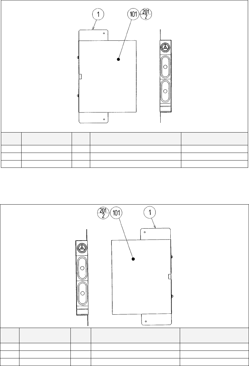
130
8.17. APC-1560 ASSY SPEAKER L
ITEM PART NO. QTY DESCRIPTION COMPONENT REF.
1 APC-1561 1 SPEAKER BRKT
101 130-5156 1 SPEAKER BOX 8OHM 20W TWEETER @ TOP
201 000-P00512-W 2 M SCR PH W/FS M5X12 (101)-2
8.18. APC-1565 ASSY SPEAKER R
ITEM PART NO. QTY DESCRIPTION COMPONENT REF.
1 APC-1561 1 SPEAKER BRKT
101 130-5156 1 SPEAKER BOX 8OHM 20W TWEETER @ TOP
201 000-P00512-W 2 M SCR PH W/FS M5X12 (101)-2
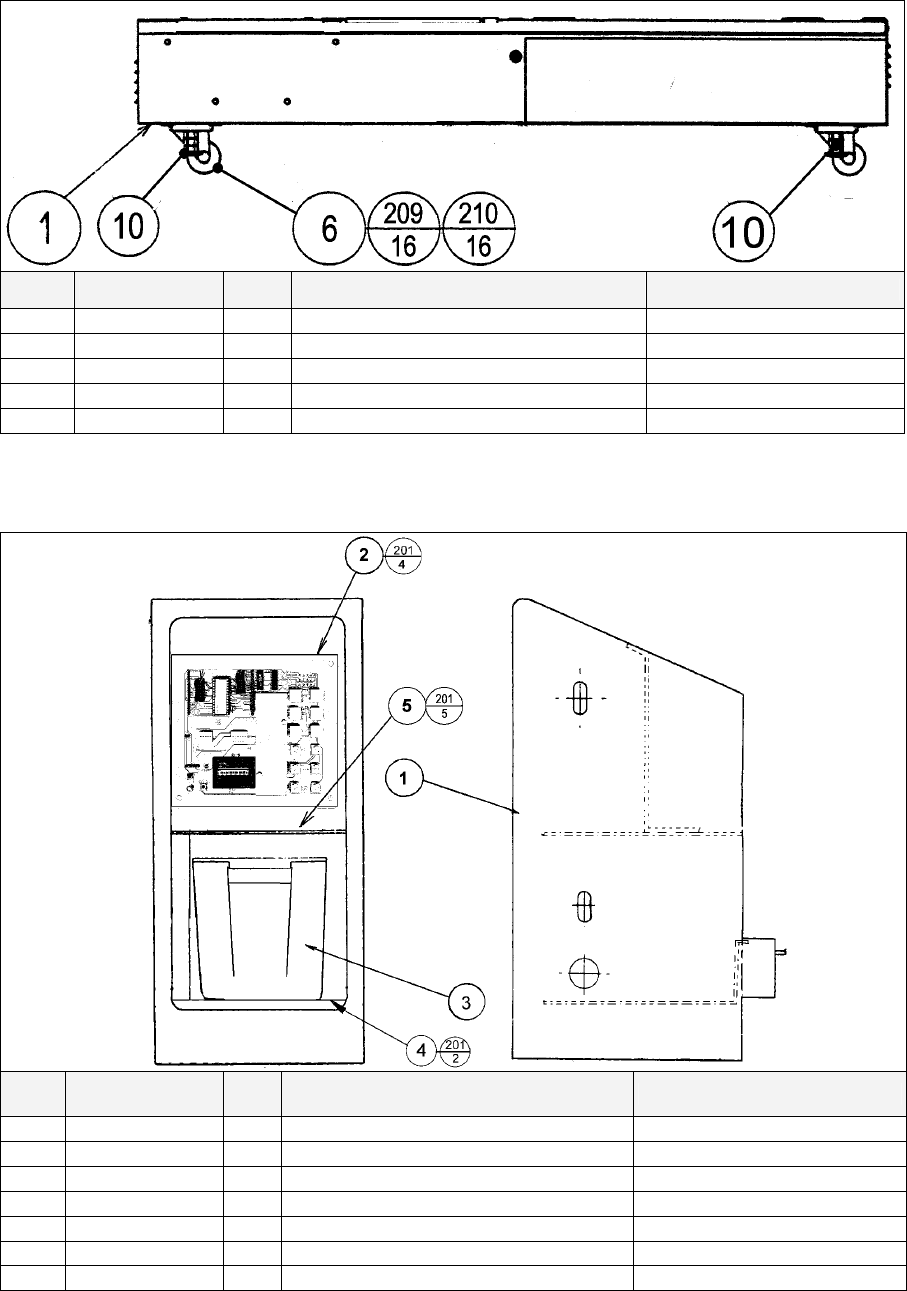
131
8.19. ORT-1120UK ASSY SUB MAIN BASE
ITEM PART NO. QTY DESCRIPTION COMPONENT REF.
1 DUT-1121UK 1 MAIN BASE
6 MA1007 4 CASTOR SWIVEL 63mm NYLON
10 601-5699UK-01 4 LEG ADJ M16X100 1L/NUT
209 030-000816 16 M8X16 BLT PAS
210 060-S00800 16 M8 WSHR SPR PAS
8.20. FRI-0300UK ASSY COINCHUTE TOWER FRI
ITEM PART NO. QTY DESCRIPTION COMPONENT REF.
1 ECA-0301UK 1 COIN CHUTE TOWER ECA
2 VTS-FRI-T 1 VTS BOARD FRI TWIN SEE TEXT
3 PP1087 1 BOX CASH FOR MINI DOOR
4 SRT-0302UK 1 CCT FLOOR TWIN
5 DUT-0302UK 1 COIN PATH PLATE
201 000-P00410-W 11 M4X10 MSCR PAN W/FS PAS (2)-4,(4)-2,(5)-5
301 FRI-61056UK 1 WIRE HARN VTS BOARD
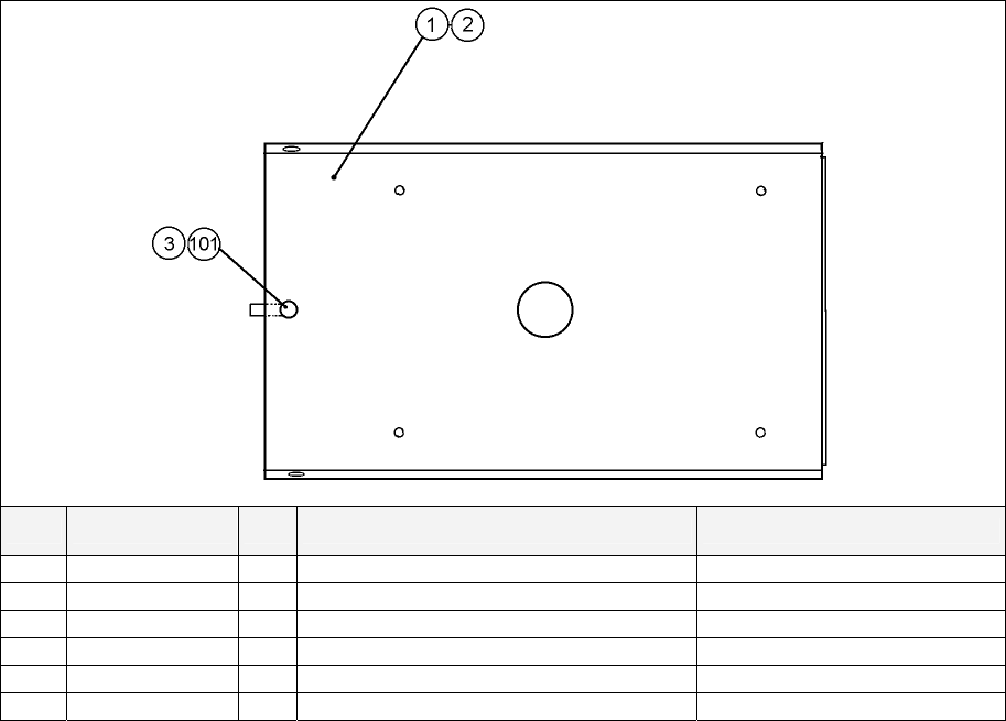
132
8.21. FRI-1510UK ASSY BASE LID R
ITEM PART NO. QTY DESCRIPTION COMPONENT REF.
1 DUT-1511UK 1 BASE LID R
2 DUT-1511-CUK 1 GASKET STRIP (1)-1
3 DUT-1511-DUK 1 LOCK TONGUE DUT (101)-1
101 220-5575UK 1 LOCK
201 050-F00400 1 M4 NUT FLG SER PAS (301)-1
301 600-9020-44K 1 WIRE HARN EARTH 200mm M4/M4 K R.FLOOR TO MAIN BASE
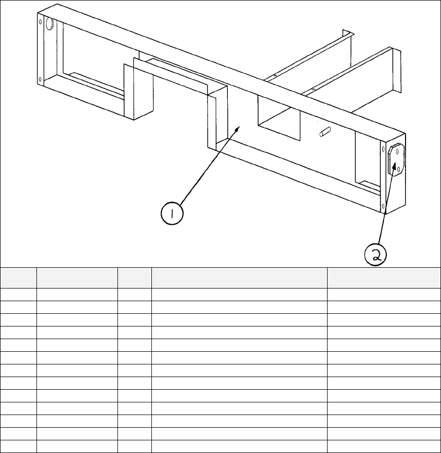
133
8.22. SPG-0500UK ASSY WIRE COVER SPG TWIN
ITEM PART NO. QTY DESCRIPTION COMPONENT REF.
1 DYN-0005UK 1 AC COVER A
2 DYN-0009UK 2 HOLE LID (1)-2
101 600-6275-0500 2 CABLE FIBER OPTIC 5mm x 500cm
201 000-P00308-WB 4 M3X8 MSCR PAN W/FS BLK (2)-4
202 050-F00400 1 M4 NUT FLG SER PAS EARTH - 1
203 280-A02000-A 5 ROUTER TWIST D20 ADH (1)-5
301 600-6817-104 1 WIRE HARN EXT AC (SPG)
302 600-6817-102 1 WIRE HARN EXT TOWER L (SPG)
303 600-6817-103 1 WIRE HARN EXT TOWER R (SPG)
304 600-6373-76 1 WIRE HARNESS PLAYER SEL EXT A
305 600-9075-44K 1 WIRE HARN EARTH 750mm M4/M4 K SUB AC-AC COVER
306 600-9030-44K 1 WIRE HARN EARTH 300mm M4/M4 K MAIN AC-AC COVER
307 600-9040-45K 1 WIRE HARN EARTH 400mm M4/M5 K AC COVER - CCT
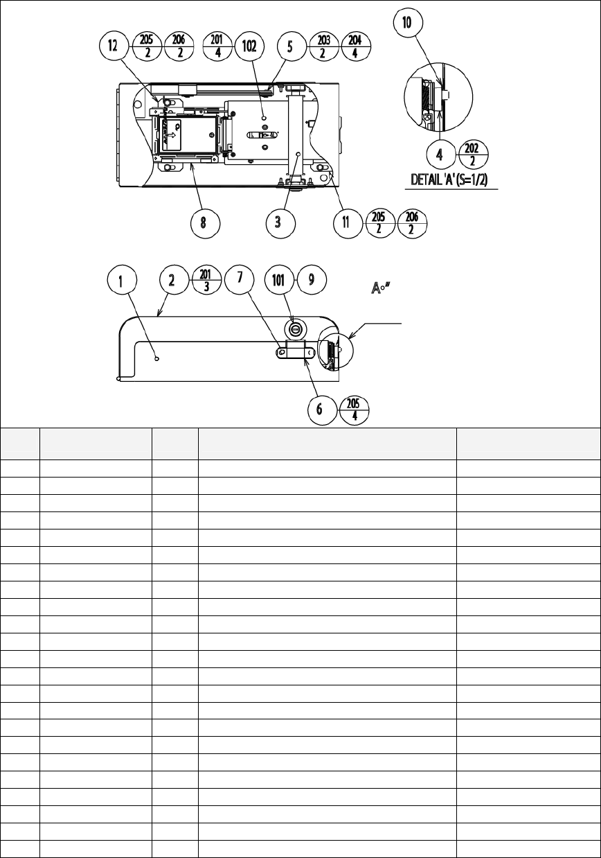
134
8.23. VOF-0450UK CARD UNIT TWIN L
ITEM PART NO. QTY DESCRIPTION COMPONENT REF.
1 CKT-0401UK 1 CARD R/W BASE TWIN
2 CKT-0402UK 1 CARD R/W COVER TWIN L
3 CKT-0403UK 1 LOCKING TONGUE NARROW
4 253-5512 1 CARD GUIDE
5 CKT-0404UK 1 PLATE STAY
6 CKT-0408UK 2 LOCK BRKT S
7 CKT-1307 2 STUD PLATE
8 VOF-0451UK 1 CARD R/W BRKT FOR VOF
9 170048 1 SPACER-L+F REF 9203602
10 CKT-0406UK 1 GATE
11 CKT-0407UK 1 INSULATOR PLATE CKT
12 VOF-0452UK 1 INSULATOR PLATE VOF
13 100-5365-0606 1 OILES BEARING 80T 0606 (2)-1
101 220-5575UK 1 LOCK (9)-1
102 601-11082 1 CARD R/W UNIT CRP-1231BR-10
103 280-A01200-A 3 ROUTER TWIST D12 ADH
201 000-P00308-W 7 M3X8 MSCR PAN W/FS PAS (2)-3,(102)-4
202 000-F02508 2 M2.5 X 8 MSCR CSK BZP (4)-2
203 065-E00500 2 DIA5 E RING (5)-2
204 068-652016 4 M6 WSHR 20OD FLT PAS (5)-4
205 050-F00400 8 M4 NUT FLG SER PAS (6)-4,(11)-2,(12)-2
206 000-F00308 4 M3X8 MSCR CSK PAS (11)-2,(12)-2
301 VOF-60050UK 1 WH CARD R/W
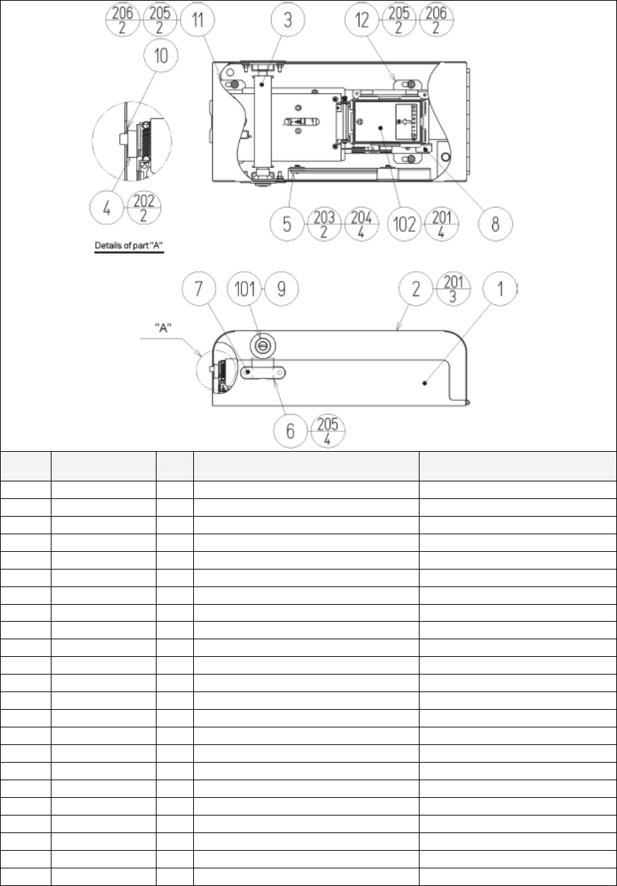
135
8.24. VOF-0460UK CARD UNIT TWIN R
ITEM PART NO. QTY DESCRIPTION COMPONENT REF.
1 CKT-0401UK 1 CARD R/W BASE TWIN
2 CKT-0422UK 1 CARD R/W COVER TWIN R
3 CKT-0403UK 1 LOCKING TONGUE NARROW
4 253-5512 1 CARD GUIDE
5 CKT-0404UK 1 PLATE STAY
6 CKT-0408UK 2 LOCK BRKT S
7 CKT-1307 2 STUD PLATE
8 VOF-0451UK 1 CARD R/W BRKT FOR VOF
9 170048 1 SPACER-L+F REF 9203602
10 CKT-0406UK 1 GATE
11 CKT-0407UK 1 INSULATOR PLATE CKT
12 VOF-0452UK 1 INSULATOR PLATE VOF
13 100-5365-0606 1 OILES BEARING 80T 0606 (2)-1
101 220-5575UK 1 LOCK (9)-1
102 601-11082 1 CARD R/W UNIT CRP-1231BR-10
103 280-A01200-A 3 ROUTER TWIST D12 ADH
201 000-P00308-W 7 M3X8 MSCR PAN W/FS PAS (2)-3,(102)-4
202 000-F02508 2 M2.5 X 8 MSCR CSK BZP (4)-2
203 065-E00500 2 DIA5 E RING (5)-2
204 068-652016 4 M6 WSHR 20OD FLT PAS (5)-4
205 050-F00400 8 M4 NUT FLG SER PAS (6)-4,(11)-2,(12)-2
206 000-F00308 4 M3X8 MSCR CSK PAS (11)-2,(12)-2
301 VOF-60050UK 1 WH CARD R/W

136
8.25. TOS-INST-TW ASSY INSTALLATION KIT TOS TWIN
ITEM PART NO. QTY DESCRIPTION COMPONENT REF.
1 TOS-0200UK 1 ASSY BILLBOARD
2 FRI-0300UK 1 ASSY COINCHUTE TOWER FRI
3 SPG-0500UK 1 ASSY WIRE COVER SPG TWIN
4 DYN-0013 1 JOINT PIPE
5 DYN-0006XUK 1 AC COVER B
6 SRT-0018UK 1 AC COVER C
7 DYN-0019UK 1 AC COVER D
9 SPG-0008 2 BILLBOARD HOLDER
10 422-0924UK 2 PLAY INSTR SH TOS MULTI 422-0924UK
13 PK0358 1 INST KIT BOX TOS TWIN
14 TOS-0004UK 2 STICKER CARD SLOT TOS A MULTI
15 TOT-0005UK 2 STICKER CARD SLOT TOF B MULTI
16 601-11358-01 3 CARD PACKAGE TOS ENG
17 601-11050-91 1 CLEANING KIT(30SHT)
18 220-5753 1 VOL CONT B-5K OHM (TOCOS) spare
101 440-CS0186UK 2 STICKER C EPILEPSY MULTI
201 030-000825-SB 20 M8X25 BLT W/S BLK (1,2,4)-4EA,(9)-8
202 068-852216-0B 20 M8 WSHR 22OD FLT BLK (1,2,4)-4EA,(9)-8
203 000-P00412-WB 15 M4X12 MSCR PAN W/FS BLK (3)-5,(5)-4,(6)-2,(7)-4
204 050-F00400 3 M4 NUT FLG SER PAS (AC UNITS)-1EA, (2)-1
205 068-441616 3 M4 WSHR 16OD FLT PAS (12)-3
401 420-5827 1 SERVICE MANUAL SANWA 31K
402 420-6799-02UK 1 SERVICE MANUAL TOS TWIN
403 OS1019 2 SELF SEAL BAG 9X12.3/4
404 540-0006-01 1 WRENCH M4 TMP PRF
405 540-0007-01 1 WRENCH M5 TMP PRF
406 540-0009-01 1 WRENCH M8 TMP PRF
407 220-5484 1 VOL CONT B-5K OHM
408 SAECE-xxx 1 DECLARATION OF CONFORMITY DEC. OF CONFORMITY TOTT
409 514-5078-5000 2 FUSE 5X20 CERAMIC SB 5000mA
411 420-6620UK 1 SERVICE MANUAL GD ROM SYSTEM
416 509-5704 1 SW MICRO TYPE (OMRON K3L13)

137
9. APPENDIX A - ELECTRICAL SCHEMATIC
9.1. WIRE COLOURS
THE WIRE COLOUR CODE IS AS FOLLOWS:
A PINK
B SKY BLUE
C BROWN
D PURPLE
E LIGHT GREEN
Wires other than those of any of the colours listed above will be displayed by 2 alphanumeric characters:
1 RED
2 BLUE
3 YELLOW
4 GREEN
5 WHITE
7 ORANGE
8 BLACK
9 GREY
If the right hand side numeral of the code is 0, then the wire will be of a single colour shown by the left hand
side numeral (see the list above).
Note 1: If the right hand side alphanumeric is not 0, that particular wire has a spiral colour code. The left
hand side character shows the base colour and the right hand side one, the spiral colour.
[Example] 51------------- WHITE/RED = WHITE wire with RED stripes
Note 2: The character following the wire colour code indicates the size of the wire.
K: AWG18, UL1015
L: AWG20, UL1007
None AWG22, UL1007
9.2. ELECTRICAL SCHEMATIC
The following pages contain the electrical schematic for this machine.

138
Schematic 1 here

139
Schematic 2 here

140
Schematic 3 here

141
SEGA AMUSEMENTS EUROPE LTD./ SEGA SERVICE CENTRE
Suite 3a
Oaks House
12 - 22 West Street
Epsom
Surrey
United Kingdom
KT18 7RG
Telephone: +44 (0) 1372 731820
Fax: +44 (0) 1372 731849
SEGA 2004
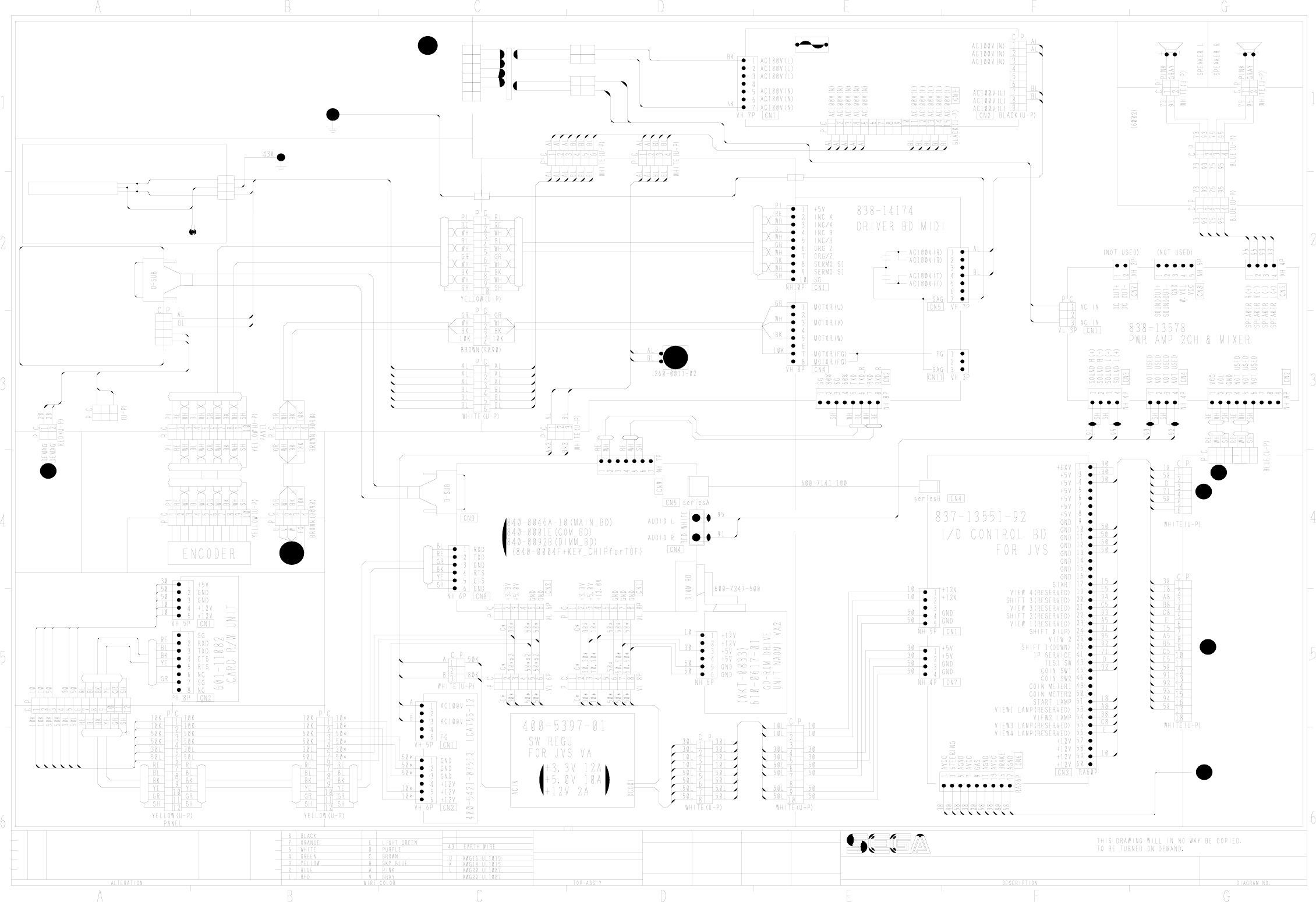
U-P PANEL
WHITE
TOF-60104UK
2 WAY M&L
600-6985-006UK
CP
1
2
2 WAY M&L
C
P
1
2
6
5
4
3
2
1
100V@6.5A
D0L
70L
560-5394UK
230V
0V
14V@10A
P C
M&L
INITIAL D 3 TWIN
FUSE 6.3A
514-5078-6300
M4 TERM
MONITOR SUPPORT
M4 TERM
EARTH STUD
TOS-00001UK
840-0091D-12
ASSY CASE NAT TOF
VOF-60050UK
CKT-62036UK
CKT-62037UK
130-5156-01
SPEAKER BOX
8 OHM 20W
130-5156-01
SPEAKER BOX
8 OHM 20W
838-11856-CE-02
TOS-0200UK
ASSY BILLBOARD
43U 43U
1
VL1P
C P
143U43U
TOF-60052UK
POD-61057UK
C P
VL1P
20
20
POD-61012UK
WHITE (U-P)
15 WAY PANEL
DEMAG
DEMAG
AC 100V
AC 100V
10
9
7
6
NCR-61002UK
To PG 2/2
Pos E1
To PG 3/3
Pos A2
To PG 3/3
Pos A1
To PG 3/3
Pos G1
To PG 3/3
Pos G1
6
5
4
3
2
1
SEGA ENTERPRISES LTD
TOS-SCM- 1/3
22-07-04
CW
APPROVEDD.CHECKED
CHECKEDDRAWN
32
7OL
DOL
JST VH
POD-61012UK
200-5949
ASSY CLR DSPL
29TYPE 31K UK
AL
BL
1
3
2
NOT USED
TOF-60101UK
ASSY MAIN BASE
TOT-4600UK
ASSY MAIN BRD
TOS-4500UK
ASSY COCKPIT
TOSF-10001UK
ASSY COCKPIT
TOS-10001UK
ASSY COCKPIT
TOS-10001UK
TOT-2500
ASSY HANDLE
MECHA
AL
BL
FRI-61003UK
FRI-61003UK
TOF-60001UK
TOT-4600UK
ASSY ELEC BD BASE
TOT-1550UK TOT-1555UK
ASSY COCKPIT
TOS-10001UK
NCR-61004UK
TOF-60009UK
TOT-60105UK
NCR-61003UK
TOF-60008UK
TOF-60007UK
TOF-60006UK
TOF-60005UK
(*=AWG18 UL1007)
TOF-60004UK
TOF-60003UK
TOF-60002UK
TOF-60003UK
TOF-60002UK
TOF-60011UK
(TOF-6005UK)
FRI-61030UK
FRI-61027UK
TOF-60021UK
TOF-60015UK
600-7009-2500
FRI-61041UK
TOT-0400UK
TOF-2000XUK
ASSY CONTROL PANEL
ASSY FLEXI TUBE
CKT-61009UK
TOF-60010UK
43K
43K
BL
AL
BL
AL
CP
3
2
1
AC UNIT
MAIN/SUB
F
TO 2/3
POS. C5 or D5
TOT-0400UK/
TOT-0700UK
FL 40W (T 12)
600-7064-031UK
TRAY - 309-5695-40-CUK
TUBE - 309-5695-40-BUK
VOF-0450UK
CARD UNIT 1P
OR
VOF-0460UK
CARD UNIT 2P
(NOT USED)
NCR-61008UK
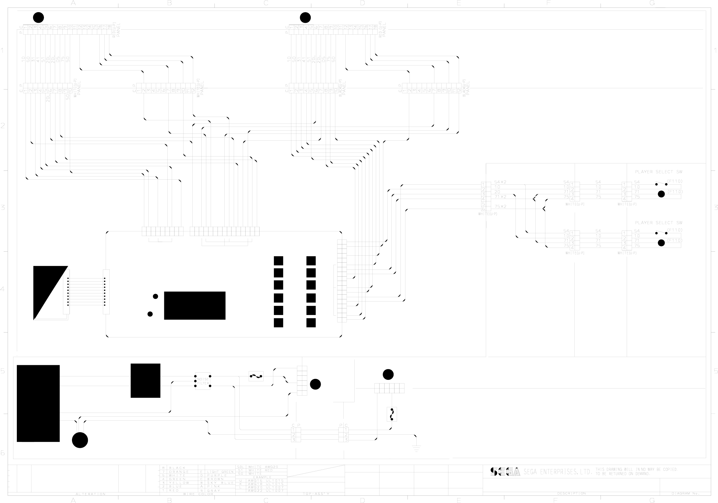
2
4
6
APPROVEDD CHECKEDCHECKED
DRAWN
USED ON ASSY
ASSY
CONTROL
PANEL
TOT-61078UK
FRI-0300UK
TOT-4600UK TOT-4600UK ASSY ELEC BASE
10001UK
TOF-2000XUKTOS-
ASSY
COCKPIT
ASSY WIRE
COVER
SPG-0500UK
TOT-4600UK ASSY ELEC BASE
ASSY AC UNIT SUB
TOT-0700UK
ASSY COINCHUTE TOWER FERRARI
ASSY AC UNIT MAIN
TOT-0400UK
FRI-0300UK
FRI-61056UK
FRI-61056UK
FRI-61056UK
FRI-61056UK
21L
43K
43K
43K
43K
TO (3/3) POS.E1 (2P)
TO (3/3) POS. E1 (1P)
TOT-61078UK
C P
C P
P C
P C
600-6373-76
C P
EP1334
20K
C0K
43K
C0K
20K
43K
43K
43K
20K
C0K
75
51
D5
41
31
FUSE
(F187)
514-5078-5000
5A CERAMIC
DRT-5000UK (SUB)
M&L
RIGHT
(F187)
C0K
20K
600-6873-001UK
C0K
20K
43K
SPG-0500UK
43K
C0K
20K
600-6817-104
LEFT
P C
C0K
(F250)
(F250)
20K
EP1379
EP1303
FRI-0300UK
600-6873-001UK
5A CERAMIC FUSE 514-5078-5000
600-6999-201UK
C0K
(F250)
20K
IEC
EP1302
SOCKET
FUSED
10A CERAMIC FUSE 514-5078-10000
600-6873-001UK
POS.B1
TO (1/3)
POS.B1
TO (1/3)
F
1P1P
2P2P
B
G
F
TOS-00001UK
CH1 FRONT
NCR-4600UK
N/CN/C
FRONT
REAR
CH2 REAR
CH1 REAR
CH2 FRONT
105
TM
SEGA
SERVICE
STATUS
LED
15
58
70
75
53
57
38
D
74
20
48
54
71
90
CH2
CH1
VOL C
DEMAG
SERVICE
TEST
VTS-FRI-T
M4 RING TERM
INITIAL D 3 TWIN TOS-SCM-2/3
22/07/04
CW
75
42
21L
D5
52
17
32
10
51
58
31
41
50
49
24L
59
39
20x2
54
70
D
24L
20L
58
48
38
57
15
59
4
5
6
1
2
3
12
13
11
8
9
10
18
15
16
17
14
7
1
2
3
4
6
5
8
9
7
4
5
6
1
2
3
12
13
11
8
9
10
15
14
7
CABLE
M&L
1
2
3
4
6
5
600-6373-77-91
(PANEL)
(PANEL)
600-6373-77-91
(PANEL)
8
9
5
6
2
3
4
7
10
1
10
8
9
5
6
2
3
4
7
1
VALIDATOR
COIN
C120
E162690
49 42
52
39 32
52
32
17
42
600-6817-102
52 52
42
32 32
42
17 17
ASSY WIRE COVER
SPG-0500UK
42
32
52
17
58
10
71 17
600-6817-103
P C
M&L
M&L
1
2
3
4
6
5
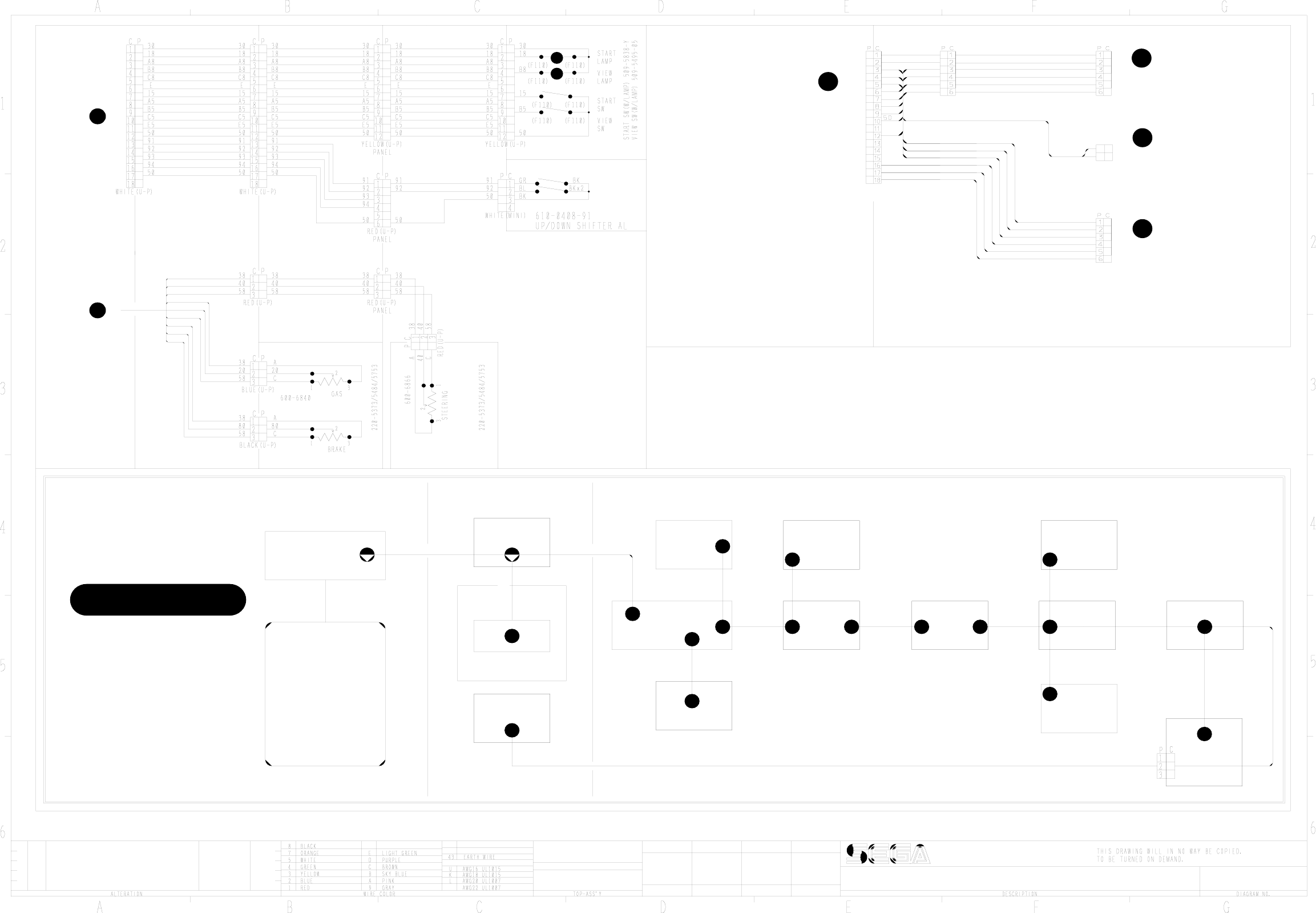
M4
TOT-0400UK
ASSY AC BRKT
M4
M4
SPG-0500UK
ASSY WIRE COVER
M5
600-9060-46K
MONITOR FRAME
M6 200-5949
TOF-2000UK
M4
CNTRL PNL STD
600-9100-44K600-9040-45K
M5
TRANSFORMER
560-5394UK
POD-1021UK
TOS-0200UK
BILLBOARD
POD-61012UK
VOF-0450UK
CARD UNIT
CKT-61009UK
600-9020-44K
600-9100-44K600-9020-44K600-9050-44K600-9030-44K
DUT-1008UK
ROOF
LID
MONITOR SUPPORT
POD-1023UK
MONITOR STAND
NCR-1104UK
WIRE COVER BOX
DUT-1121UK
MAIN BASE
600-9020-44K
FRI-1510UK
BASE LID R
M4
M4
M4
M4
M4
M4M4M4M4M4M4M4
TOT-0400UK
AC BRKT
POD-61026UK
TOF-60103UK
EARTH MAP
75
50
D5D5
50
75
51
41
31
D5
75
TOS-2150UK
ASSY SW PLATE
To PAGE 1/3
POS. G4
To PAGE 1/3
POS. A4
TO PAGE 1/3
POS. G6
TO PAGE 1/3
POS. G5
G
600-9075-44K 600-9030-44K
600-9040-45K
REPEAT
AS FOR
PLAYER 1
(EXTERNAL STUD)
FRI-0300UK
COIN CHUTE TOWER
SHARED
PLAYER 2 - "MASTER" PLAYER 1 - "MASTER"
600-7064-031UK
TOF-60100UK
TOF-2000XUK
CONTROL PANEL
TO PAGE 2/3
POS A1, D1
SPG-0500UK
ASSY WIRE COVER
TOS-10001UK ASSY COCKPIT
P C
20L
20L
20L
1
2
20L
U-P RED
3220L
20L
PANEL
RED (U-P)
B
A
To PAGE 1/3
POS. G4
C
32
SEGA ENTERPRISES LTD
INITIAL D 3 TWIN TOS-SCM-3/3
DRAWN CHECKED D.CHECKED APPROVED
CW
22/07/04
TOS-00001UK
TOS-10001UK
ASSY COCKPIT
NCR-61011UK TOF-60017UK TOF-60019UK
TOF-60018UK
TOF-60016UK
FRI-61042UK
TOF-60105UK
SPG-2200 TOF-2500
32
42
52
31
51
41
10
50
52
42
32
50
10
50
10
32
