Arcade Lindbergh Manual User
2013-11-20
User Manual: Arcade Lindbergh Manual
Open the PDF directly: View PDF ![]() .
.
Page Count: 88

MANUAL
KU2496-024
• Before using this product, read this manual carefully to understand the
contents herein stated.
• After reading this manual, be sure to keep it near the product or in a
convenient place for easy reference when necessary.
IMPORTANT
© SEGA CORPORATION, 2007
Suite 3A, Oakes House, 12/22 West Street,
Epsom, Surrey. KT18 7RG. Tel: +44 (0) 1372 731 820
SEGA AMUSEMENTS EUROPE LTD
420-6942UK
1st Printing
Lindbergh Universal Cabinet Upright Type Manual

Warranty
The warranty period for this product is three months from the date of shipment from our premises.
Within the warranty period, we will repair, free of charge, any fault occurring for reasons that are
the responsibility of the manufacturer. If any fault occurs, stop using the affected product, remove
the power plug from the outlet and contact the service contact specied at the back of the manual.
This warranty is not applicable to faults occurring for any of the reasons listed below (repairs, if
possible, will require payment).
(1) Faults caused by natural disaster or other act of God.
(2) Faults caused by ooding, or by damage from falling.
(3) Faults caused by incorrect operation.
(4) Faults caused by usage that contravenes the installation conditions or specification
conditions specied in this manual.
(5) Changes caused by modications to equipment specications (addition to, or alteration of,
the equipment), where not specied by this company.
(6) Faults caused by the user, whether by accident or design.
(7) Faults caused by failure to service the machine (maintenance and inspection) at the
required intervals.
(8) Overhauls, regular maintenance, movement and re-installation of large machines.
(9) Faults caused by the machines other than this product.
Malfunctions (screen display disturbance etc.) caused by electrical noise generated by
other machines.
(10) Components that are deemed to be consumable supplies.
i) Fluorescent tubes and lamps
ii) Switches and buttons
iii) Levers and joysticks
iv) Fuses and other components
v) Standing displays, ags and other promotional materials
vi) Items specied in this manual to be consumable supplies
(11) Network faults not caused by the product.
i) Network environment on the premises (LAN cables, switching hubs etc.)
ii) Circuits, providers and other elements of the Internet environment
iii) Server failure and similar incidents
The warranty period of chairs, cabinet stands and other options provided with this product may
differ from that of the product itself.
This company bears no liability of any kind for loss of prots or indirect damages resulting from
the inoperability of this product.
Lindburg.indb 2 2/16/2007 19:11:56
Table of contents
Table of contents
i
E0-0603 420-6942
Warranty
Read this first
Table of contents ................................................................................................ i
Introduction to this manual ............................................................................. iii
1 Handling precautions.......................................................................................................1
2 Installation location precautions ....................................................................................4
3 Operation precautions .....................................................................................................6
4 Part names ........................................................................................................................8
5 Accessories ......................................................................................................................9
6 Installation and assembly procedure ...........................................................................11
6-1 Installation work ......................................................................................................11
6-2 Precautions on using a service outlet ..................................................................16
7 Precautions when moving the console ........................................................................17
8 Internal switches and the coin meter ...........................................................................18
9 For mounting the control panel ....................................................................................20
9-1 Replacing the control panel ...................................................................................20
9-2 Replacing the instruction sheet.............................................................................23
10
10 The coin selector ............................................................................................................24
11 The monitor (LCD display) ............................................................................................27
11-1 Safety precautions for handling the monitor .....................................................27
11-2 Cleaning the screen surface ................................................................................28
11-3 Monitor adjustment method .................................................................................29
12
12 Replacing the fluorescent lamp ....................................................................................43
13 Replacing the game board ............................................................................................45
13-1 How to remove the game board...........................................................................45
13-2 Replacing the design components......................................................................47
13-3 The game board power supply voltage adjustment knob .................................49
14
14 Regular inspection list ...................................................................................................50
Lindburg.indb 1 2/16/2007 19:11:57
Table of contents
ii
15 Parts listParts list ..........................................................................................................................51
16 Wire color reference table .............................................................................................80
17 Overall wiring diagramsOverall wiring diagrams.................................................................................................81
Lindburg.indb 2 2/16/2007 19:11:57
Introduction to this manual
iii
Specication
Area required: 820mm (W) x 827mm (D)
Height: 2,097 mm
Weight: 122kg (with Lindbergh board mounted)
Power consumption, maximum current:
460W, 2A (AC230V, 60Hz)
(When using Virtua Fighter)
Monitor: 32V wide-screen LCD display
Introduction to this manual
This manual provides information and detailed explanations on the
LINDBERGH UNIVERSAL CABINET
including electronic assemblies, electrical mechanisms, maintenance management, spare parts and all other
operation-related matters.
This manual is intended to be read by the owners, managers and operators of this product. Before using this product,
read the manual and be sure that you understand it thoroughly. If this product does not operate correctly, contact
the service contact stated in this manual, and make sure nobody other than the appropriate technician touches any
internal systems. When requesting mechanical repairs or purchasing parts (consumable supplies), ll in and fax the
“On-site service request form”, “Service components order form” or “Advance loan and repair request form”. If
you lose this manual, use the “Service components order form” to obtain a replacement. This manual does not cover
compensated accidents involving personal injury or property damage, but important information is bounded by a
thick line and marked with the word “Important” and icons.
Incorrect operation which fails to follow these indications can impair
the performance of this product or prevent it from functioning at all.
IMPORTANT
Lindburg.indb 3 2/16/2007 19:11:57
Introduction to this manual
iv
Tasks in this manual which are specied to be performed by on-site maintenance
staff or service engineers, and tasks which are not explained by the manual, should
not be attempted by anyone who lacks the necessary level of knowledge and skill.
Electric shocks or other serious accidents could result.
Replacement of parts, maintenance and inspection, and repairs to malfunctions should be performed by on-site
service staff or service engineers. This manual directs that hazardous tasks, in particular, should be performed by
service engineers with the necessary specialist knowledge.
This manual denes on-site maintenance staff and service engineers as follows
:
On-site maintenance staff: A person with experience of the maintenance of amusement machines and
vending machines etc., who is involved in the day-to-day maintenance of
equipment in an amusement arcade or store, under the management of the
owner or operator of this product. Tasks include assembly and installation
of machines, maintenance and inspection, and the replacement of units and
consumable supplies.
On-site maintenance staff perform the following tasks:
Assembly and installation of amusement machines and vending machines
etc., maintenance and inspection, and the replacement of units and
consumable supplies.
Service engineer: A person involved in the design, manufacture, inspection and maintenance
servicing of machines for an amusement machine manufacturer. A
technical high school graduate or person with equivalent specialist
knowledge in electrical, electronic and mechanical engineering, who
is engaged in the maintenance management and repair of amusement
machines on a day-to-day basis.
Service engineers perform the following tasks:
Assembly and installation of amusement and vending machines, repair and
adjustment of electrical, electronic and mechanical components.
Denition of maintenance staff and service engineers
WARNING
Lindburg.indb 4 2/16/2007 19:11:57
Handling precautions
1
1
When installing and inspecting this product, pay close attention to the following points and handle the machine
accordingly, to allow safe gameplay.
Improper handling, in contravention of the points below or of the precautions stated in this manual, can cause
personal injury and mechanical damage.
● Always turn the power switch off before working on the machine. Electric shocks
or short-circuit accidents could result.
The manual will always state when it is necessary to work on the machine with
the power switched on.
● Do not plug in or unplug the power plug suddenly. Electric shocks or other
accidents could result.
● Do not plug in or unplug the power plug with wet hands. Electric shocks
accidents could result.
● Do not leave power or earth cables exposed in aisles and other areas where
people walk. Exposed cables could be damaged, leading to electric shocks or
short-circuit accidents.
● Do not place objects on top of the power cable, or otherwise damage it. Electric
shocks or res could result.
● Do not pull on the power cable unnecessarily, either during or after installation.
Electric shocks or res could result.
● If the power cable is damaged, order a replacement from the vendor, or from the
ofce stated in this manual. Continued use with a damaged power cable could
cause re, electric shock or ground leakage.
● A ground connection is required. Electric shocks could result without appropriate
grounding.
● Use fuses of the specied rating. Use of a fuse in excess of the specied rating
could result in re or electric shock.
● The IC board and other connectors must be fully connected. If they are not fully
inserted, they could cause electric shocks.
● Never make any changes (additions or alterations) to the specication dened by
the manufacturer.
• Electric shocks or res could result. Such changes could also cause the user
of the product, or others nearby, to feel unwell or suffer accidental injury.
• This company bears absolutely no liability, including for compensation to third
parties, for accidents that occur involving a product that has been altered from
its standard specication.
● Always perform regular servicing (Maintenance and inspection) as specied in
this manual.
● The current capacities for game boards in this product are 3.3V 12A, 5.0V 15A,
12V 10A. Never use game boards which require capacity above these values. Use
of such boards would cause overheating and ignition.
Handling precautions
1
WARNING
Lindburg.indb 1 2/16/2007 19:11:58
2
Handling precautions
1
● Only a logic tester should be used for circuit inspection on IC boards.
Note that normal circuit testers cannot be used.
● Use a soft, dry cloth for cleaning the surface of the monitor. Do not
use chemicals such as thinners or benzene.
● Stat ic char ge from th e human body can damage elec trical
components on an IC board. Before starting work on an IC board,
always touch a grounded metal surface, or take other action to
discharge static electricity from your body.
● Some of the components used in this product were not designed
and manufactured specifically for it. The manufacturers of such
components may, for their own reasons, alter the specications of
those components, or cease manufacturing them. In such cases, it
may become impossible to repair or replace them, either during or
after the warranty period.
IMPORTANT
Lindburg.indb 2 2/16/2007 19:11:58
Handling precautions
3
1
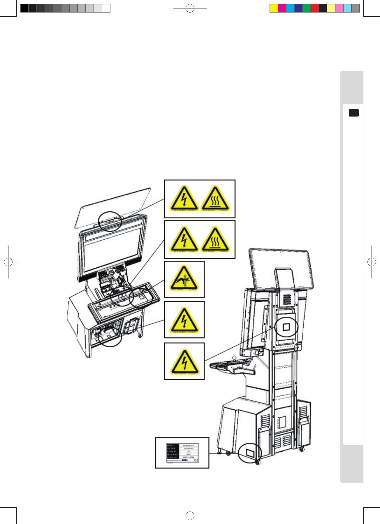
Labels
Our products have a label affixed to them stating the
product serial number and electrical specification.
Another label states the service contact for requesting
repairs and ordering parts.
When requesting repairs or making other inquiries,
check the serial number and model name before calling.
The serial number references registered information
about the product. Even for machines of the same
model, the parts used may differ depending on the time
of production. The product may also have been altered
for improvement after this manual was published. Please
state the serial number when contacting us, to enable a
rapid response in such cases.
Warning indications
Our products carry adhesive or attached labels or printed
markings in places where there is a potential hazard, to
warn of the risk. These warning indications are intended
to prevent customers from suffering accidents, and to
avoid risks related to maintenance work.
Some areas within the cabinet, such as high-voltage
parts, can cause accidents when touched. Pay close
attention to warning indications when servicing the
product. In particular, repair or replacement tasks not
described in this manual should only be attempted by a
service engineer with electrical knowledge. Customers
acting in contravention of warnings should stop such
actions, to avoid accidents.
Lindburg.indb 3 2/16/2007 19:11:58
4
Installation location precautions
2
This product is a game machine for indoor use. Do not install it outdoors.
Even indoors, do not install it in places such as the following: Such locations can
cause re, electric shock, injury and breakdowns.
● Areas exposed to leakage of rain or other water, or in very humid places, such as
close to an indoor pool or shower.
● Areas exposed to direct sunlight, close to heating equipment, or other hot
places.
● Areas lled with ammable gas, or near to chemicals or hazardous substances
that are highly ammable or volatile.
● Areas with high dust concentrations.
● Inclined surfaces.
● Areas of intense vibration.
● Close to safety equipment such as emergency exits and re extinguishers.
● Areas outside the appropriate usage temperature (ambient temperature) range of
5-30 °C.
Installation location precautions
2
Limits of usage conditions
● Always check the electrical specications.
Always check that the power source, voltage and frequency where the product
is installed match the specication. A label stating the electrical specication is
afxed to the product.
Use with a different electrical specication can cause re and electric shock.
● The installation location must be equipped with a breaker and ground connection
for the product. If it is not used with its own breaker and ground connection, re
and electric shock could result.
● Indoor wiring to the product should be single-phase 100V AC with capacity
for at least 15A 240V AC with a capacity of 13A. Use with a different electrical
specication can cause re and electric shock.
● Always provide the product with a dedicated power supply that has a ground-
fault interrupter. If the power supply used does not have a ground-fault
interrupter, a re could result from a ground fault.
● Do not attempt to clean this product using high pressure equipment such as a
jetwash.
● Do not connect multiple devices through extension cables and taps. Excessive
electrical load can cause overheating and re.
● When an extension cable is used, it must be rated at 13A or more. Use of a cable
below of the specied rating could result in re or electric shock.
WARNING
WARNING
Lindburg.indb 4 2/16/2007 19:11:59
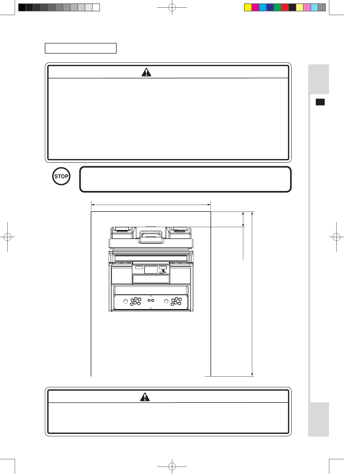
Installation location precautions
5
2
Operating oor area
● When this product is in use, it requires an area with a minimum width of 0.9m,
and a depth of 1.6m. If a user falls over during play and bangs his or her head,
it could cause major damage, so the area specied in this manual is absolutely
necessary.
● Always provide the ventilation space specied in this manual. Do not block the
ventilation holes. Overheating and re could result.
● This company bears absolutely no liability, including for compensation to third
parties, for accidents that occur when the product is used in an area smaller than
that specied in this manual.
Door dimensions of at least 0.9m wide and 1.8m tall are required for
moving this product into the building.
900mm
1600mm
150mm
Figure 2
To prevent accidents, allow sufficient space where this product is installed, to
accommodate busy times. If there is not enough space, customers could contact or
bump into each other, causing accidents and problems.
IMPORTANT
WARNING
WARNING
Lindburg.indb 5 2/16/2007 19:11:59
6
Operation precautions
3
Operation precautions
3
Before starting to operate this product, check the following points to prevent
accidents:
● Operate this product under illumination that is sufciently bright for reading the
warning indications, to avoid causing dizziness, headache or other symptoms in
players or other customers. Inadequate lighting could cause users to feel unwell,
and could also cause incidents due to contact or collision between customers.
● Be sure to adjust the monitor correctly. Do not operate the monitor with noise
or distortion in the image. An incorrectly adjusted screen image can cause
dizziness, headache or other symptoms in players or other customers.
● Provide rest facilities for use by any player who feels unwell.
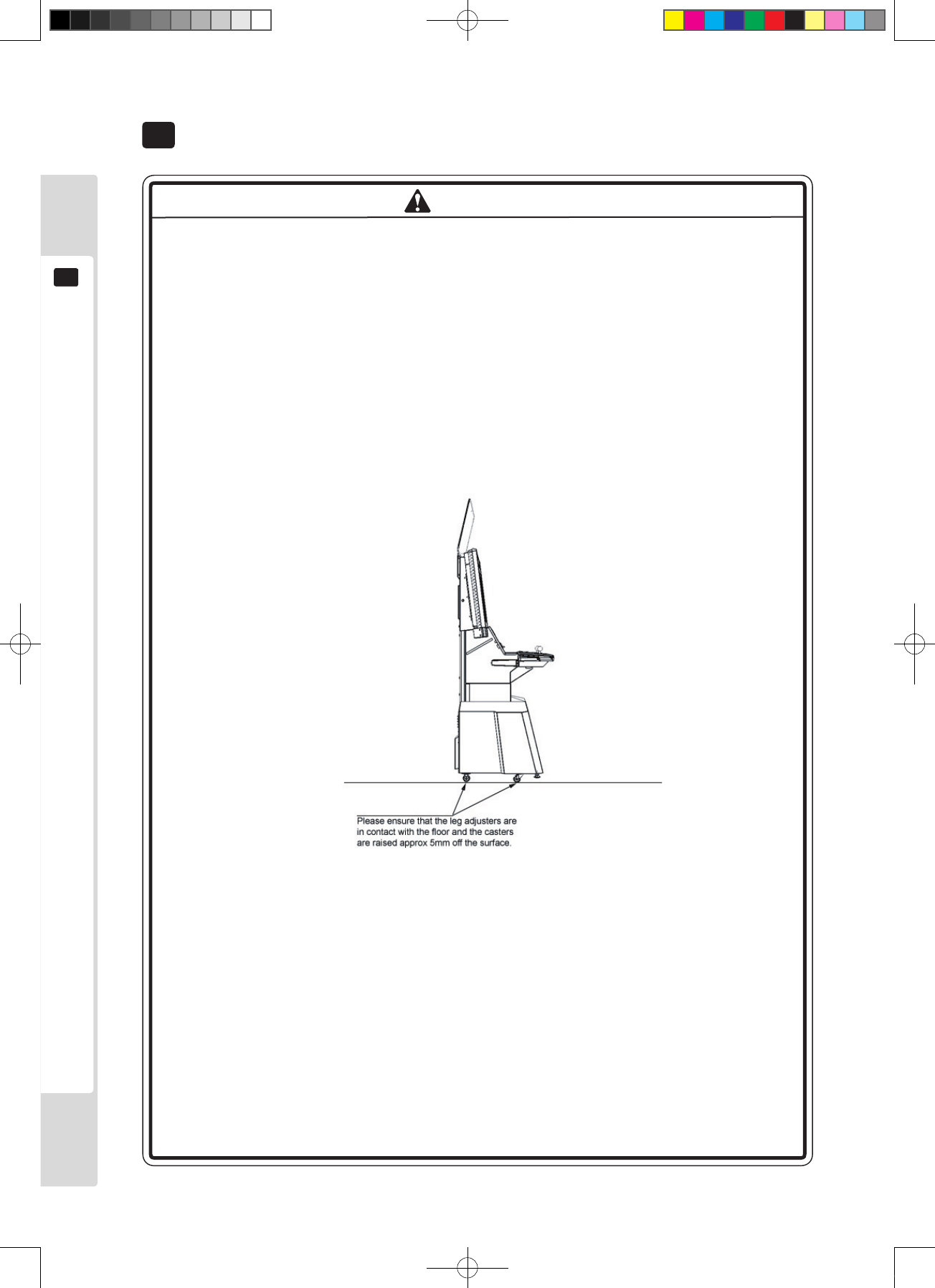
● Check that all adjusters are touching the ground. If they are not, the cabinet
could move and cause an accident.
● Do not place heavy objects on top of this product. Falling objects or damage to
components could result.
● Do not climb on top of this product. Falling or tipping accidents could result. Use
a step ladder to inspect high parts.
● Check that none of the doors or covers are broken or missing. Electric shocks
accidents could result.
● Do not place any objects such as the following on this product, on or inside the
control panel, on the seat, on the ceiling or nearby: Electric shocks, short-circuit
accidents or damaged components could result.
Flower vases, plant pots, cups, water containers, cosmetics, chemicals or
containers holding water etc.
● This product is only for use in the European Union. Use of this product overseas
could cause accidents or damage.
WARNING
Lindburg.indb 6 2/16/2007 19:12:00
Operation precautions
7
3
Operating precautions (customer-related precautions)
● Do not allow the following types of people to play on this product. Accidents or
injuries could result.
• People who cannot walk unaided.
• Hypertension and heart disease patients.
• People who have experienced muscle spasms or loss of consciousness while
playing television games etc.
• People with neck or spinal diseases.
• People strongly under the inuence of alcohol.
• Pregnant women.
• People who experience motion sickness.
• People who act in contravention of the warning indications on the machine.
● People who never felt unwell as a result of light stimuli, but whose physical
condition may cause symptoms such as dizziness or headache while playing.
In particular, young, developing children are very likely to feel unwell while
playing, so instruct such children that they can only play under the supervision
of a parent or guardian.
● Advise those who have begun to feel unwell to undergo a medical examination.
● Make sure heavy objects and drinks are not placed on top of this product. They
could result in accidents due to falling objects and electric shock accidents due
to spilt drinks.
● Do not allow people to insert hands, ngers or foreign objects carelessly into the
openings or door gaps of this product. Electric shocks or short-circuit accidents
could result.
● Immediately stop anyone who leans or climbs on this product. It could tip over,
or the person could fall.
● Do not allow people to unplug the power plug. Electric shocks or short-circuit
accidents could result.
● Immediately stop anyone who hits, kicks or otherwise uses violence on this
product. It could break or tip over, and broken parts or the falling machine could
cause injury.
WARNING
NOTE
Lindburg.indb 7 2/16/2007 19:12:00
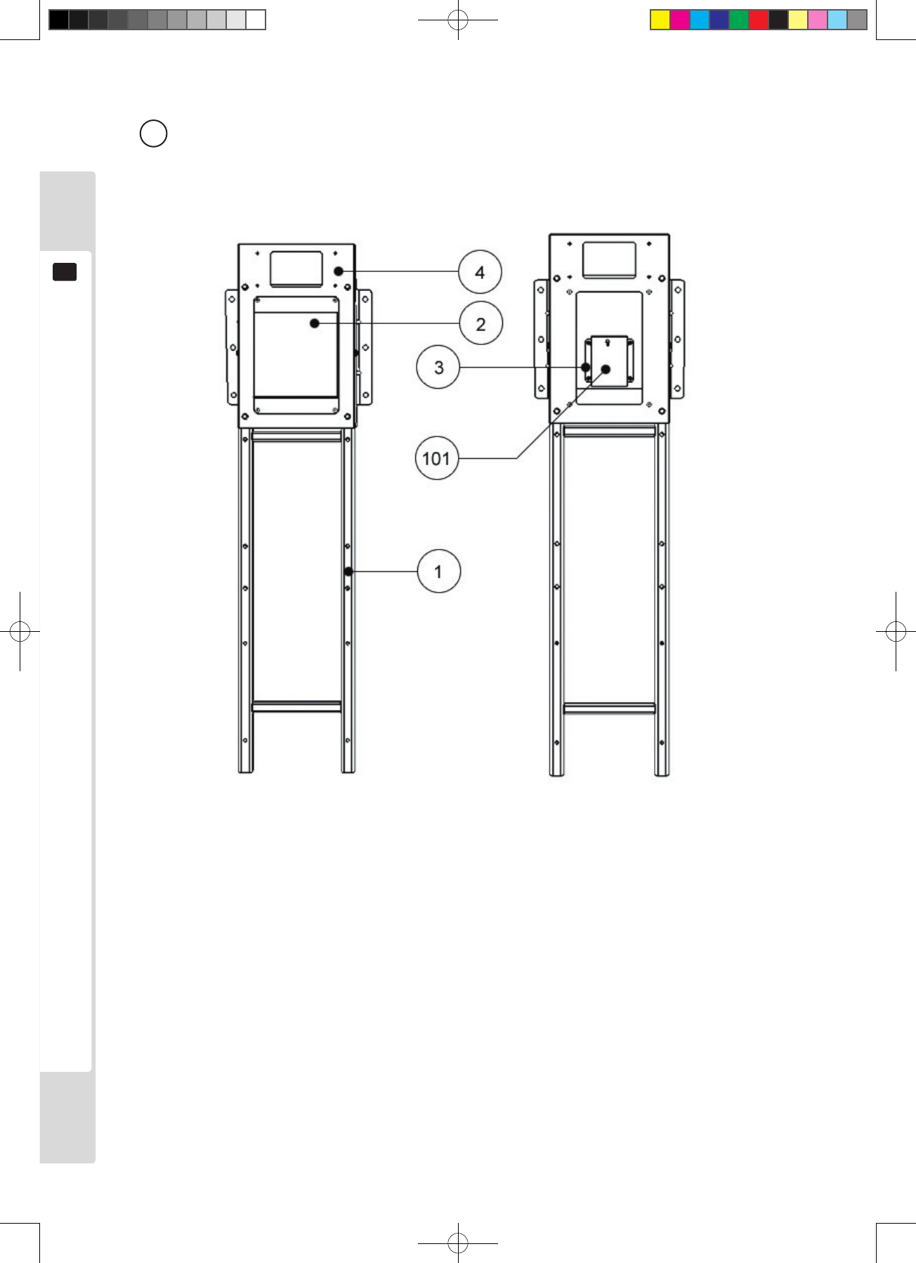
8
Part names
4
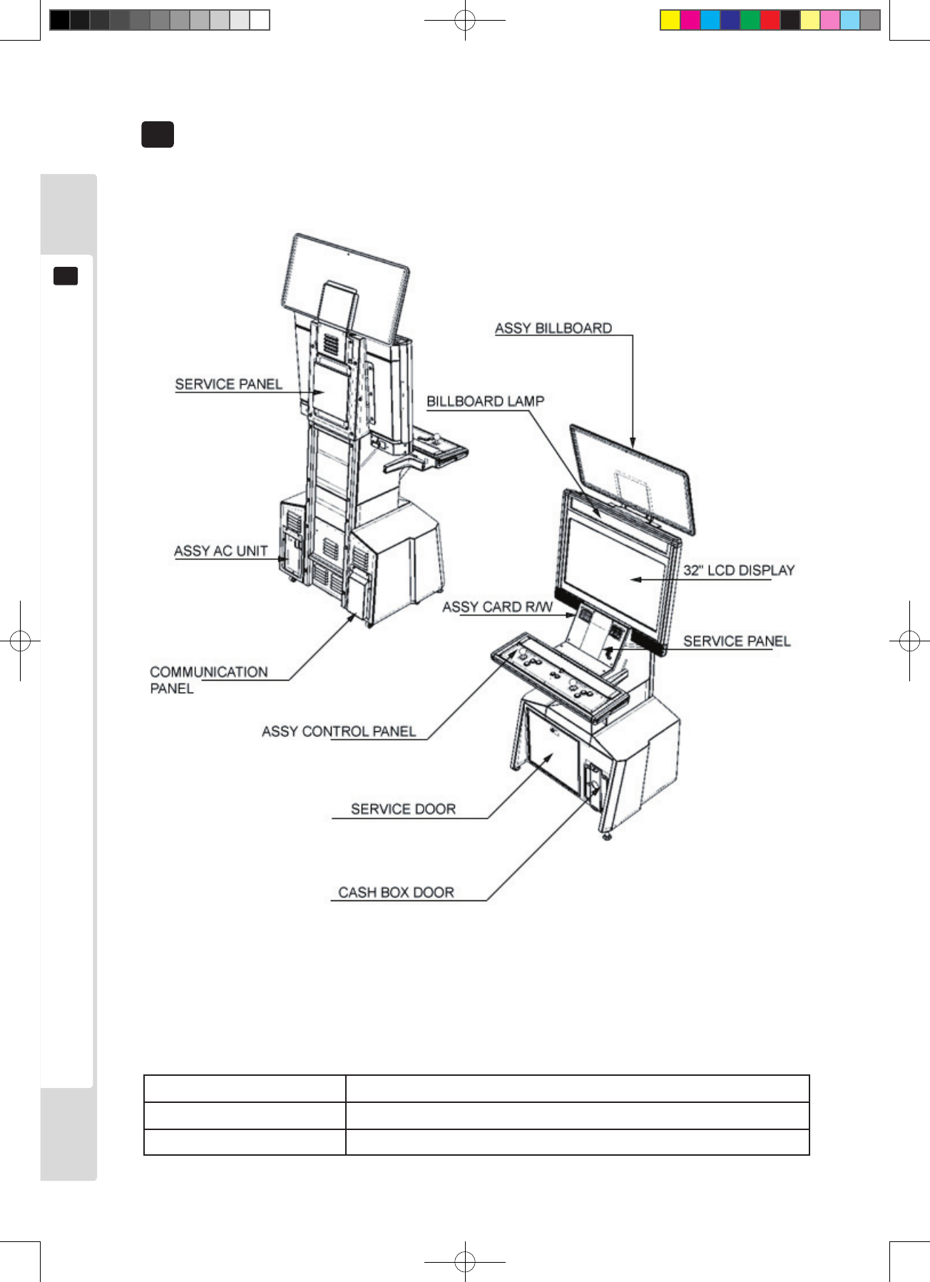
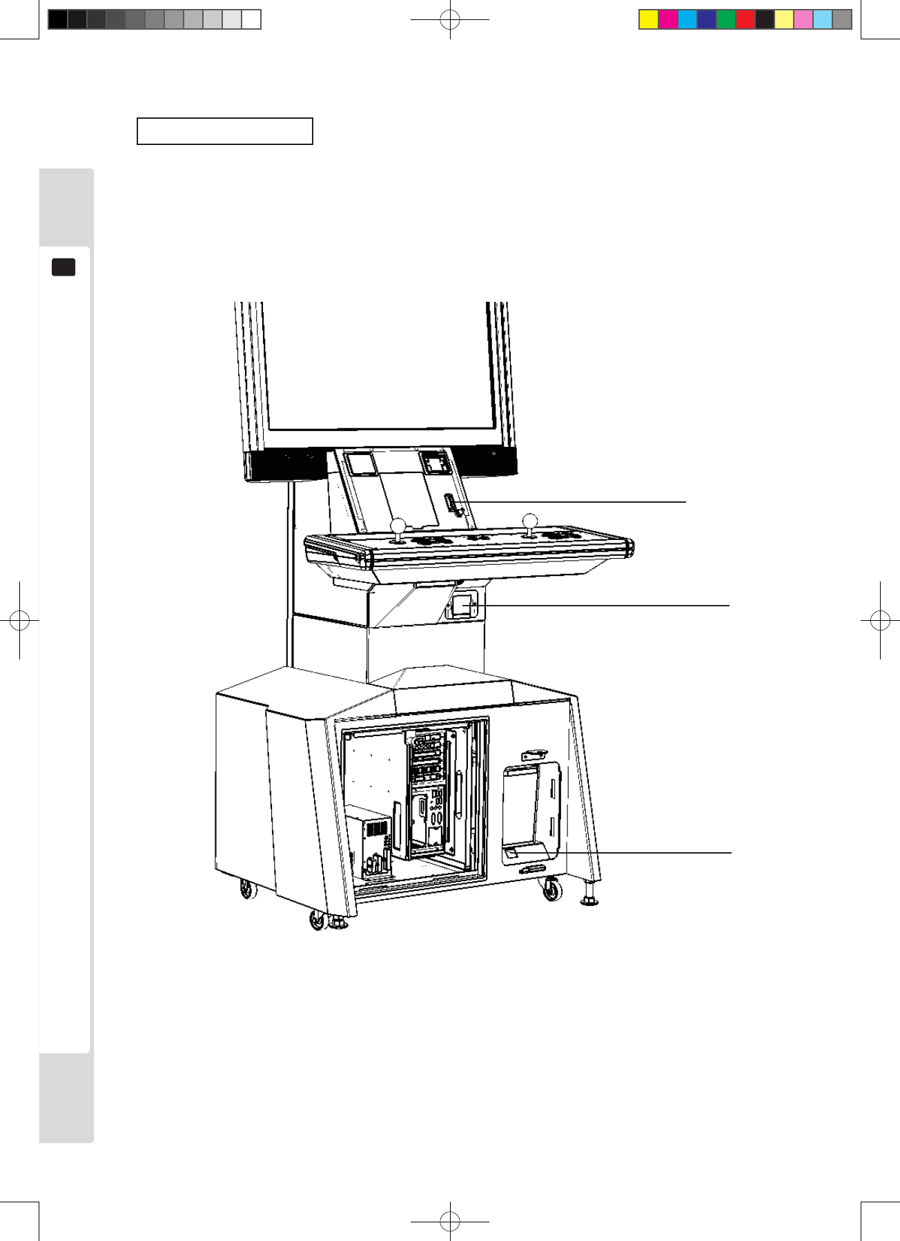
Part names
4
Table 4 Main dimensions
Dimension
Cabinet 820 mm(W) x 827 mm(D) x 1,800 mm(H)
Complete cabinet 820 mm(W) x 827 mm(D) x 2,100 mm(H)
Figure 4a
Figure 4b
Lindburg.indb 8 2/16/2007 19:12:01
Accessories
9
5
Accessories
5
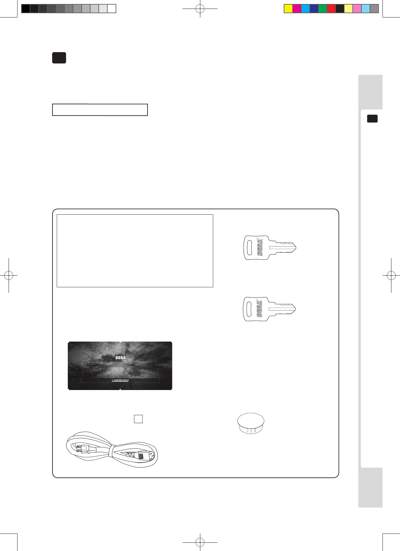
Check that all the parts listed below are present when delivered. Parts marked as “Spare” in the Application etc.
column are consumable parts, but are provided as spares. Refer to the back cover for consumable parts other than
those in this table.
Table 5 List of accessories
Part name Instruction manual
Part number (Q’ty) 420 - 6942UK (1)
Application etc. This manual
Explanatory diagrams
Parts with no stated part number have either not been
registered with parts, or cannot be registered. Store such
parts carefully because it may not be possible to sell them
even if the user wishes to purchase them.
Master key
To open and close door
Key
(2)
For the cashbox door
Anti-bacterial cap switch
253-5442 (6)
For the control panel, see chapter 9.
Billboard sheet
LCA-0002 (1)
The billboard may be already attached or
packaged separately, depending on the game
which is installed when the machine is shipped.
Replacement harnesses
This is an accessory which varies according to the game which is installed when the machine is shipped. The
replacement harnesses listed below may be packed with this product as an accessory, to make it usable with our
Naomi/2 or Lindbergh. They will already be installed if the machine is shipped with game boards of those types. In
future, replacement harnesses other than those below may be provided as accessories.
1 For Naomi, Naomi2. : LCA-60027
1 For Lindbergh. : LCA-60028
Attached to the inside of the service
door when shipped.
Power cable
600-6729-01 (LM1227 & LM1246)
For installation, refer to 6-13 3
Lindburg.indb 9 2/16/2007 19:12:03
10
Accessories
5
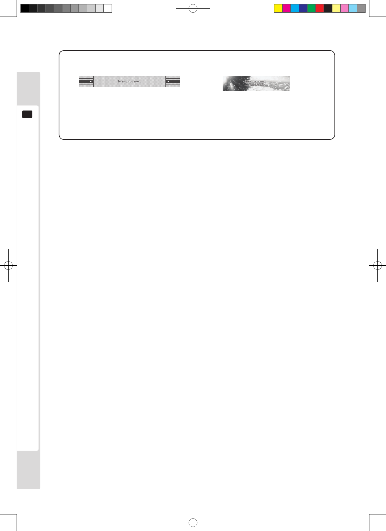
Instruction sheet Sub-instruction sheet
The control box may be already attached
or packaged separately, depending on the
game which is installed when the machine is
shipped.
The entry lid may be already attached or
packaged separately, depending on the game
which is installed when the machine is
shipped.
Lindburg.indb 10 2/16/2007 19:12:03
Installation and assembly instructions
11
6
Install this product as described in this manual. Improper installation may result in
personal injury and mechanical damage.
Installation and assembly instructions
6
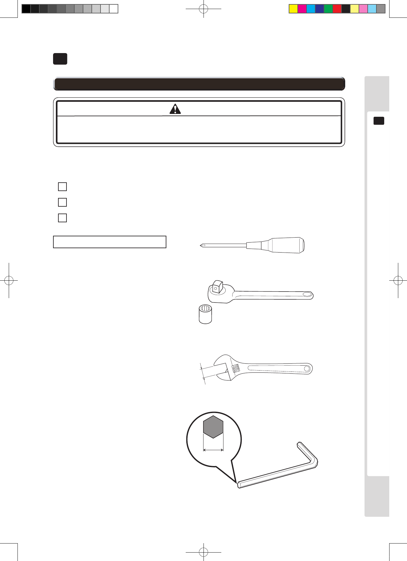
Installation of this product consists of the following three main steps:
1 Billboard attachment
2 Fastening in the installation location (adjustment of the adjusters)
3 Connection of power supply and ground connections
Philips screwdriver (for M4 screws)
Socket wrench
(for M6 hexagonal bolts and nuts)
Spanner (for M16 hexagonal bolts)
24mm
Tools required for installation
WARNING
Width across
flats
6-1 Installation work
Lindburg.indb 11 2/16/2007 19:12:04
12
Installation and assembly instructions
6
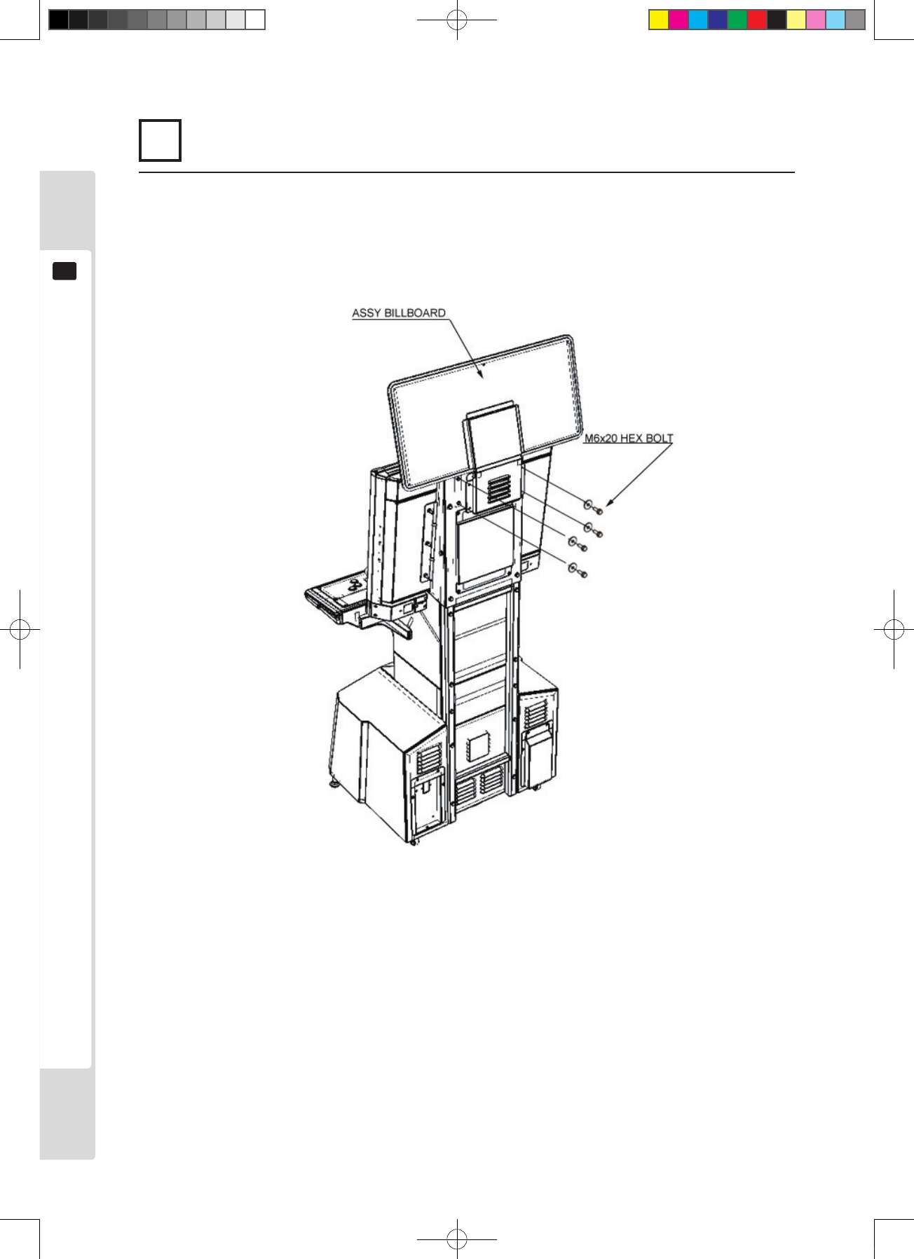
1 Attaching the billboard
1
Use four hexagonal bolts to attach the billboard holder to the cabinet.
Figure 6.1a
Lindburg.indb 12 2/16/2007 19:12:04
Installation and assembly instructions
13
6
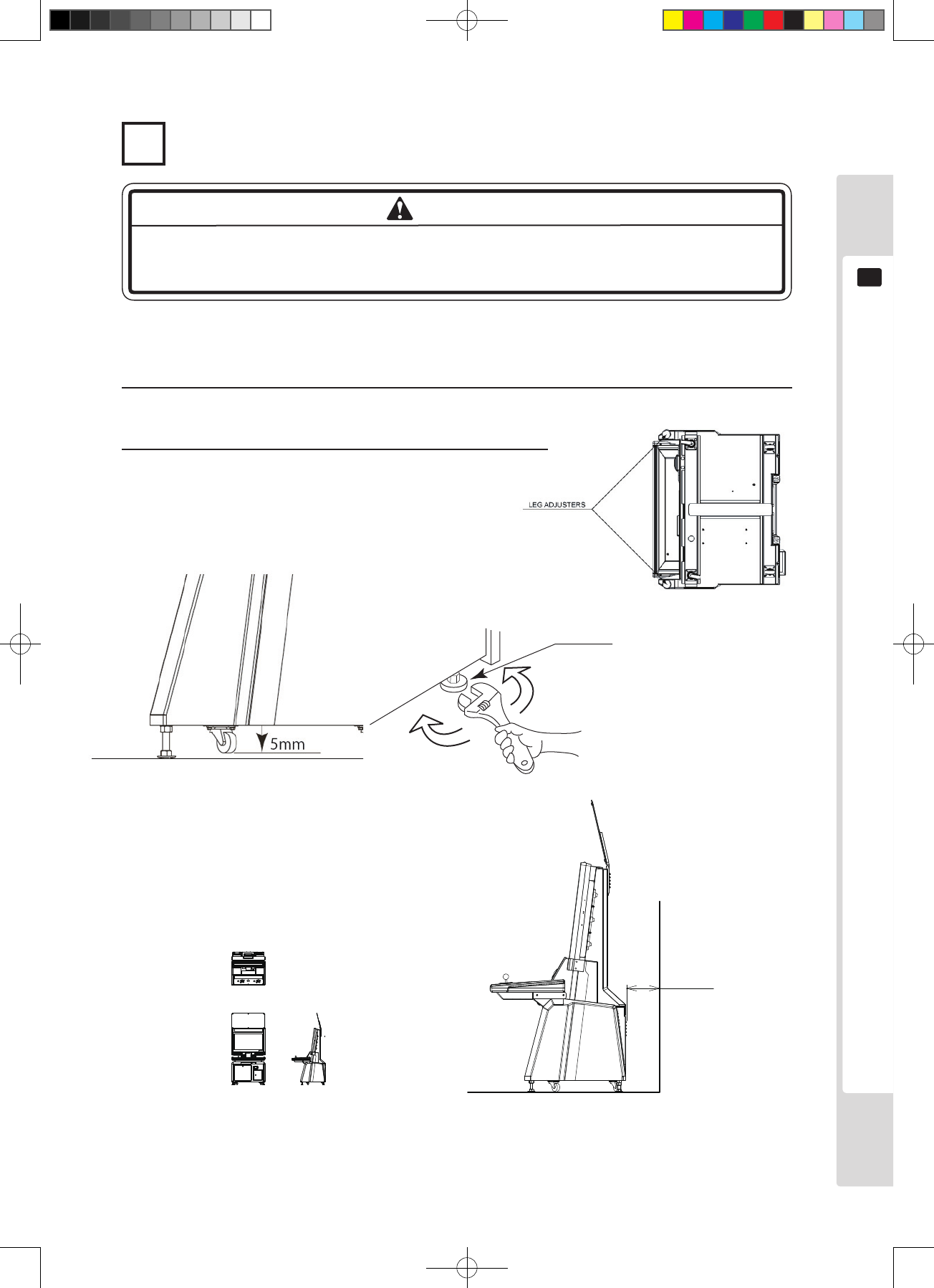
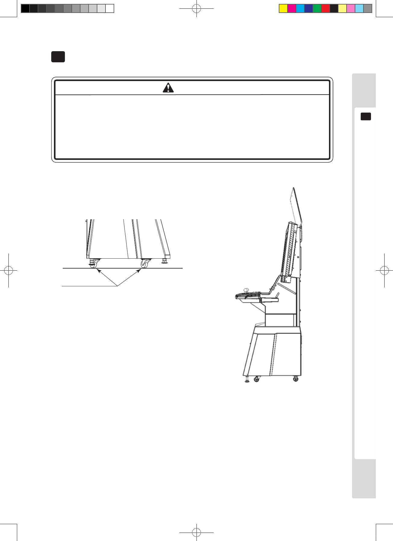
2 Fastening in the installation location (adjustment of the adjusters)
Make sure all adjusters touch the oor. If they do not, the cabinet could move and
cause an accident.
There are four casters and four adjusters on the bottom of the cabinet. Once the installation position is determined,
move the adjusters down to the ground and adjust them so that this product is level.
1
Move the machine to the installation position.
Figure6.1c Underside plan
150mm
Figure 6.1e
1/100 scale.
Refer to the layout leading to
the installation position.
Figure 6.1f
Allow space for air movement on
the side with ventilation openings.
2
Bring the adjusters into contact with the ground. Use a spanner to
adjust the four adjusters so that the product is held level.
Figure6.1c Underside plan
Adjuster
WARNING
Lindburg.indb 13 2/16/2007 19:12:07
14
Installation and assembly instructions
6
● Use a power supply equipped with a ground fault interrupter. If the power supply
used does not have a ground-fault interrupter, a re could result from a ground
fault.
● This product comes complete with both UK and European mains leads. Only
operate this product with the mains leads supplied or mains leads of the same
type and rating. Using mains leads other than those supplied or mains leads of a
different rating may result in electric shock, short circuit or a re hazzard.
● Do not leave power cables exposed. Exposed cables could trip people and suffer
damage. Electric shocks or short-circuit accidents could result from damaged
cables. Run cables where they will not impede people's movement, or cover
them.
● Always protect any cable that runs across the oor. If the power cable is exposed,
it will be vulnerable to damage and could cause electric shock accidents.
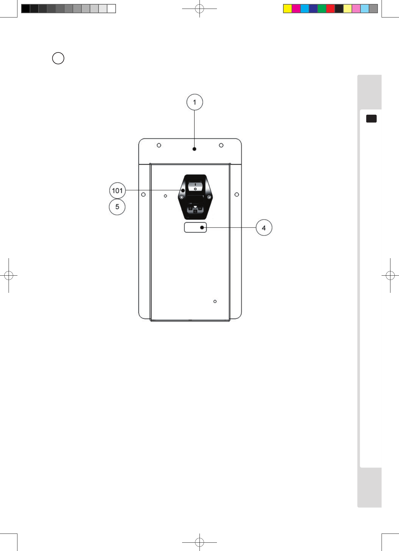
3 Connection of power supply and ground connections
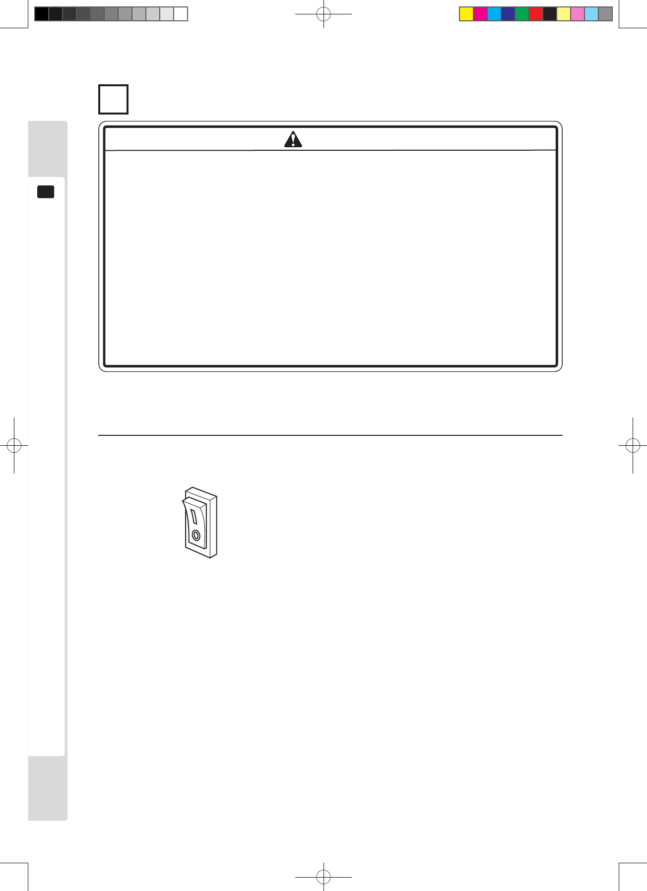
There is an AC bracket at the back of the machine. It has a Mains Switch (ON/OFF), a protection fuse and an inlet
for connecting power cables.
1
Check that the main switch is switched off.
Figure 6.1g
Main switch off
WARNING
Lindburg.indb 14 2/16/2007 19:12:08
Installation and assembly instructions
15
6
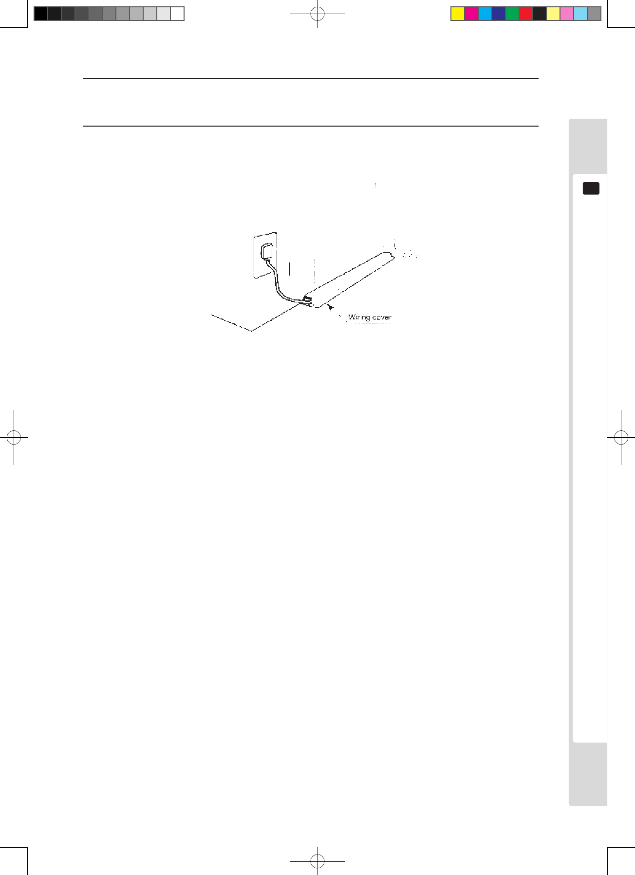
2
Plug the power plug of the power cable securely into the socket, and plug the connector opposite the plug
securely into the inlet of the AC unit.
3
Connect the power cable (and grounding cable). Attach a wiring cover to protect the power and earth cables.
Figure 6.1i
Lindburg.indb 15 2/16/2007 19:12:08
16
Installation and assembly instructions
6
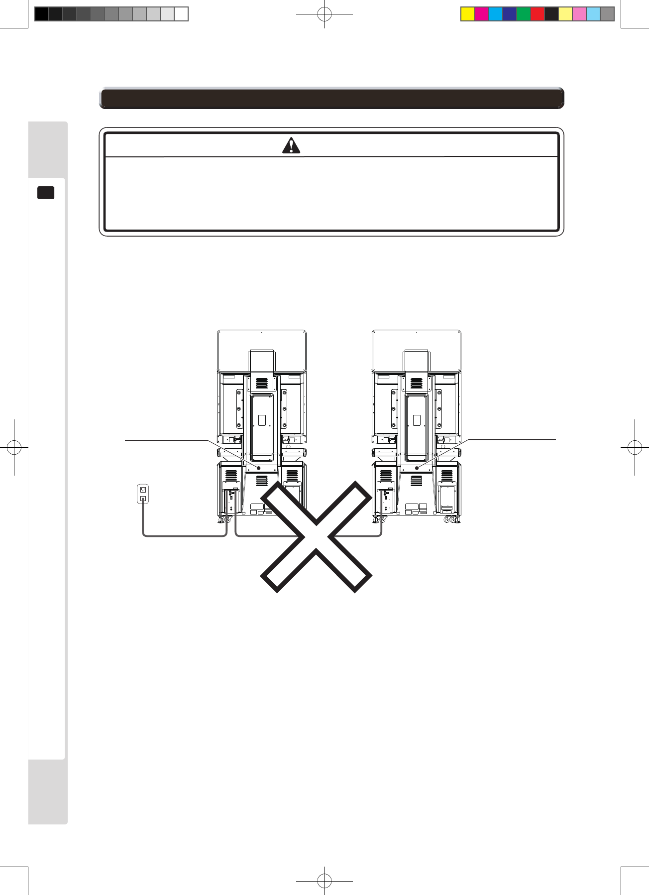
The current capacity of the service outlet on the machine is 5A.
Overheating and ignition could result if devices with combined maximum current in
excess of 5A are connected to the service outlet. That is a very dangerous situation,
which must be avoided.
It is not possible to connect one Lindbergh-equipped cabinet to the service outlet of another, as the maximum current
capacity would be exceeded.
Head-to-head connection of one additional cabinet is possible, provided it is not a Lindbergh cabinet.
LINDBERG-equipped LINDBERG-equipped
Figure 6.2
WARNING
6-2 Precautions on using a service outlet
Lindburg.indb 16 2/16/2007 19:12:09
Precautions when moving the console
17
7
Precautions when moving the console
7
● Unplug the power plug before moving the machine. Moving the machine with the
plug plugged in could damage the power cable and cause re and electric shock.
Take care not to damage the cable by treading on it or trapping it while moving
the machine.
● Do not push strongly on the top of the cabinet. That could tip the cabinet forward
and cause an accident.
Casters on ground
Figure 7a
Figure 7b
WARNING
Lindburg.indb 17 2/16/2007 19:12:10
18
Internal switches and the coin meter
8
Internal switches and the coin meter
8
● Never touch places other than those specified. Touching other places could
cause electric shock or short circuit accidents.
● Take care not to damage the wiring. Electric shocks or short-circuit accidents
could result from damaged wiring.
Adjust the volume to an appropriate level for the surroundings.
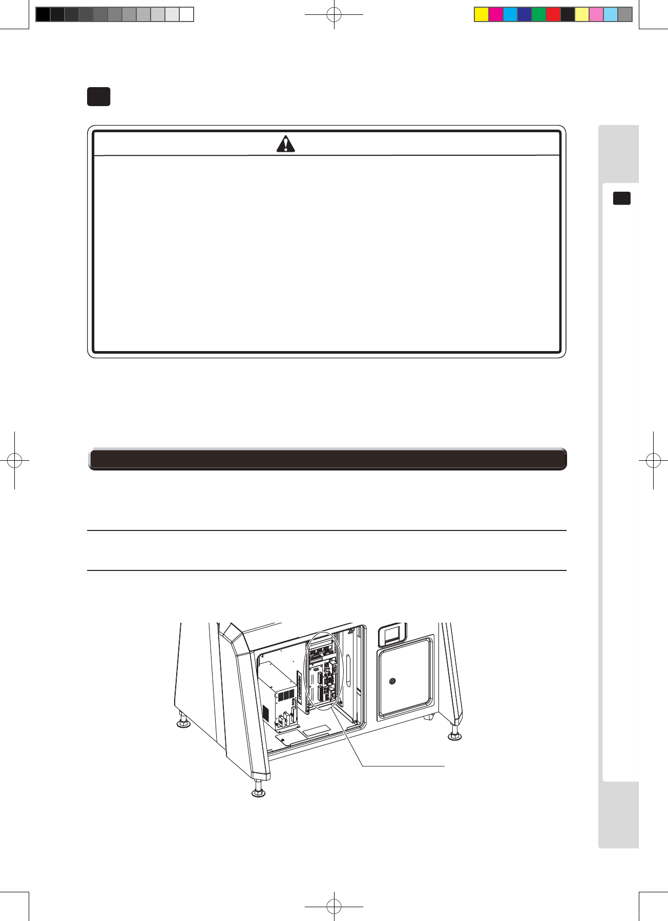
The entry lid opens when the lock on the back is unlocked. When the entry lid is open, the internal switches can be
seen inside.
Unlock
Switch unit Entry lid
Figure 8a
Figure 8b
IMPORTANT
WARNING
Lindburg.indb 18 2/16/2007 19:12:11
Internal switches and the coin meter
19
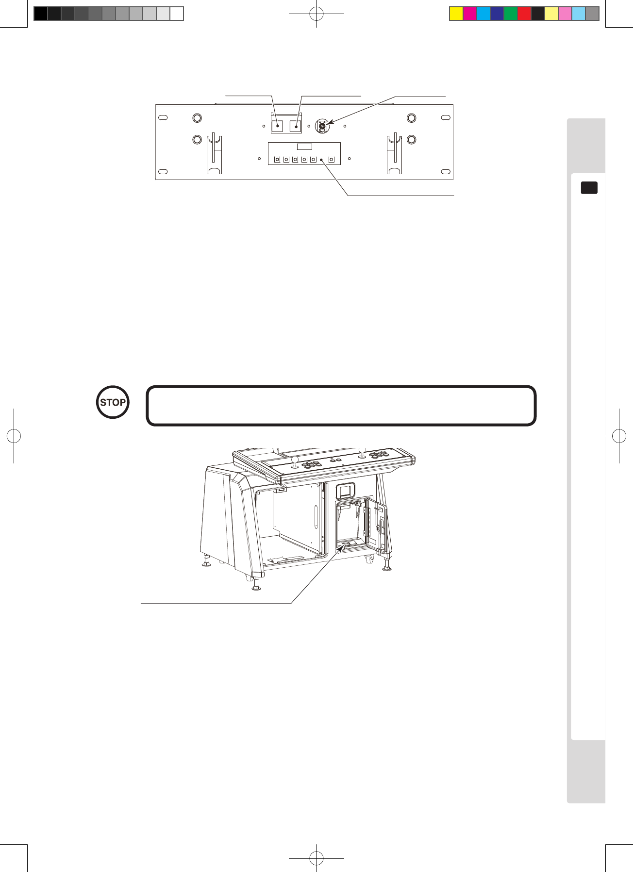
8
Figure 8c
Test button Service button Volume VR
Monitor adjustment board
See chapter 11
Test button : This puts the game board into test mode.: This puts the game board into test mode. This puts the game board into test mode.
Service button : This is the service credit button. The coin meter does not count up.
Volume VR : This adjusts speaker volume.
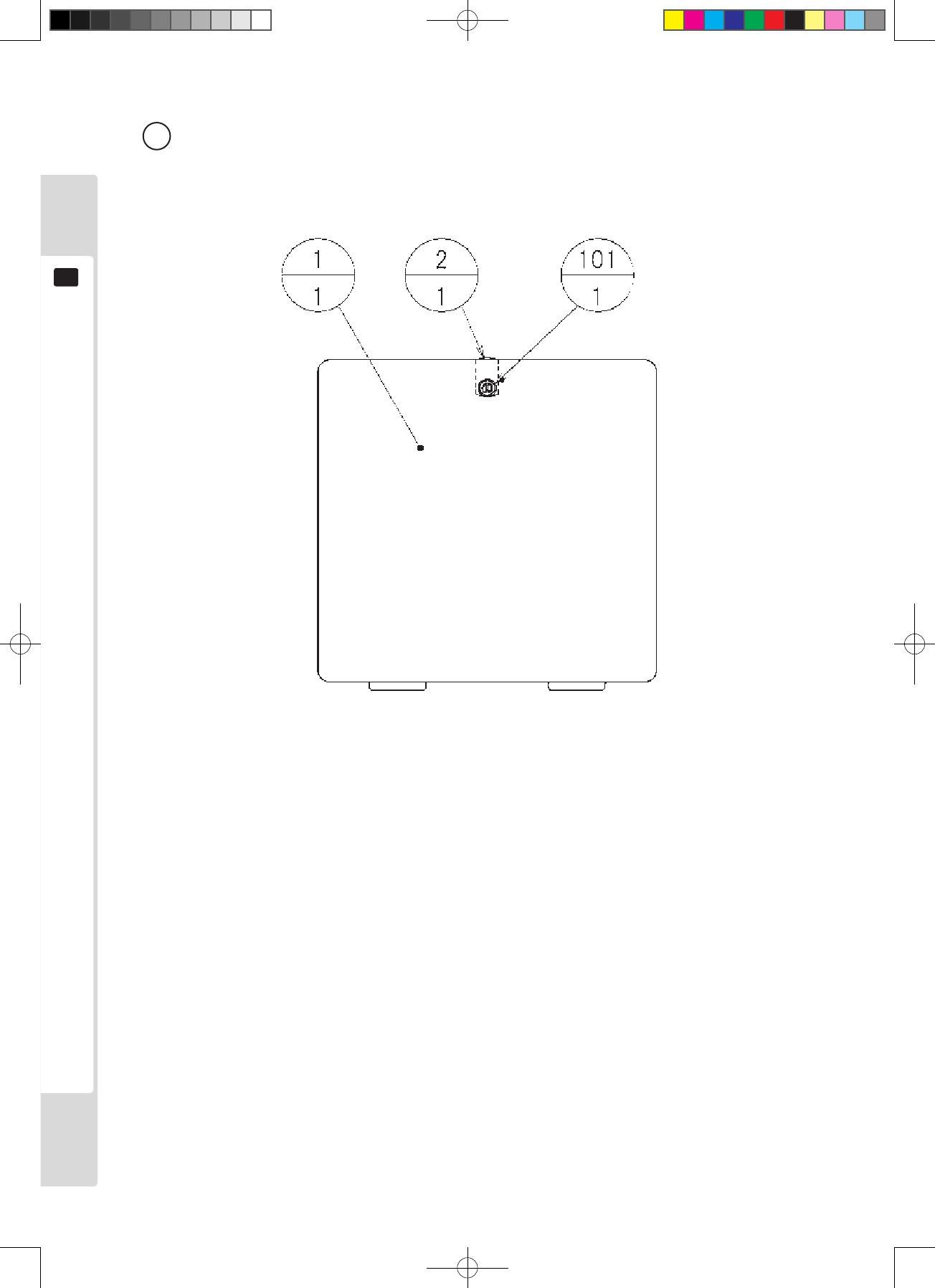
There is a coin meter inside the cash box door.
The game cannot be played if the coin meter circuit is disconnected.
Coin meter
Counts the number of coins inserted
Figure 8d
IMPORTANT
Lindburg.indb 19 2/16/2007 19:12:13
20
For mounting the control panel
9
● Always turn the power switch off before working on the machine. Electric shocks
or short-circuit accidents could result.
● Take care not to damage the wiring. Electric shocks or short-circuit accidents
could result from damaged wiring.
For mounting the control panel
9
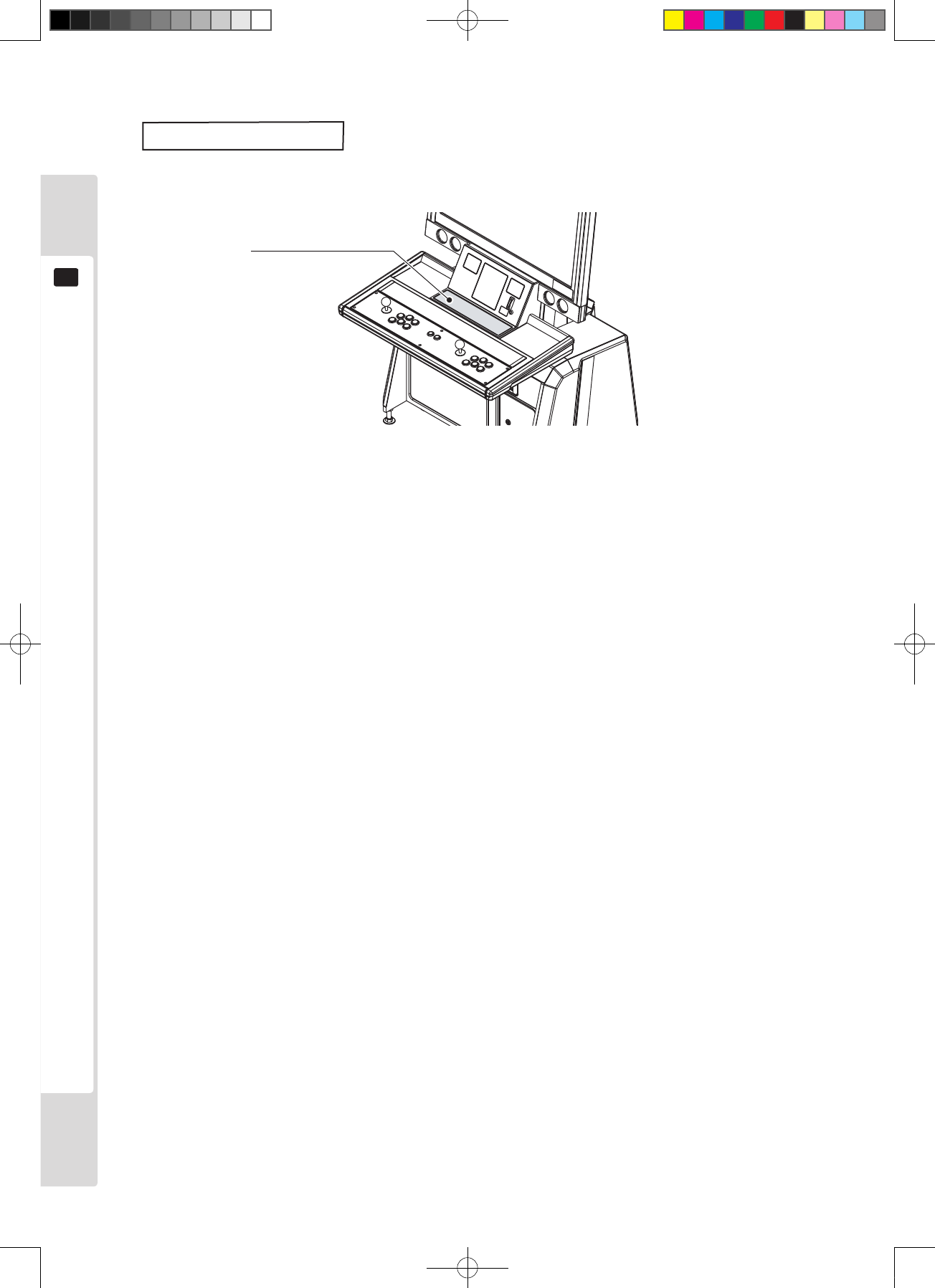
● Take care to avoid trapping your ngers when opening and closing the control
box upper cover.
● The control box upper cover can close unexpectedly under its own weight,
potentially trapping fingers. Support it securely in place when working with it
open.
● If you remove the bolts and nuts fastening the control panel in place, it will fall,
causing an accident. Support the control panel securely in place when removing
it.
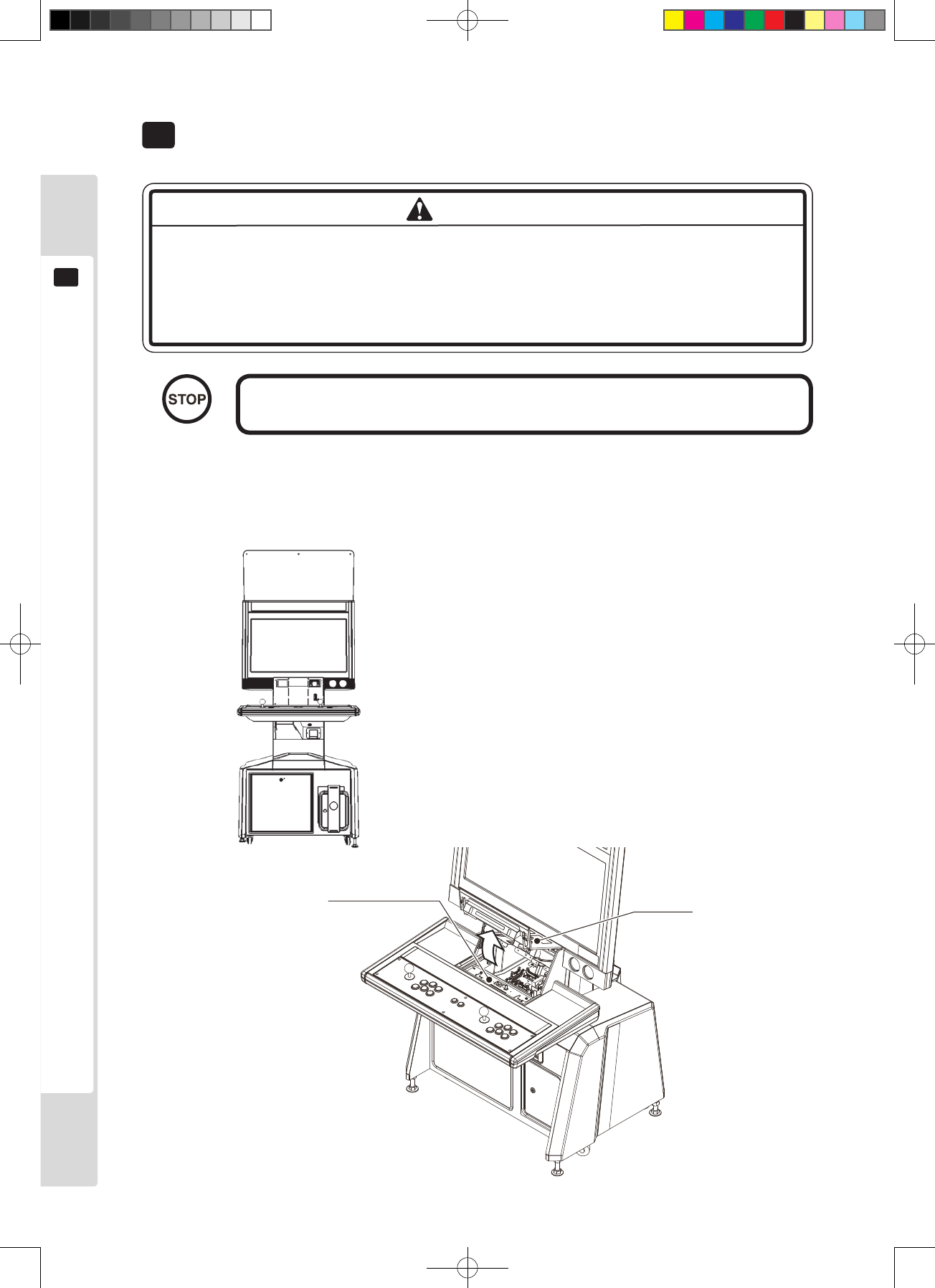
1
Use the main switch of the AC unit or the sub-power switch behind the service door to turn the power supply
off.
2
Unlock the lock on the back of the control box, then open the entry lid.
Unlock
Entry lid
Figure 9.1a
WARNING
WARNING
9-1 Replacing the control panel
Lindburg.indb 20 2/16/2007 19:12:14
For mounting the control panel
21
9
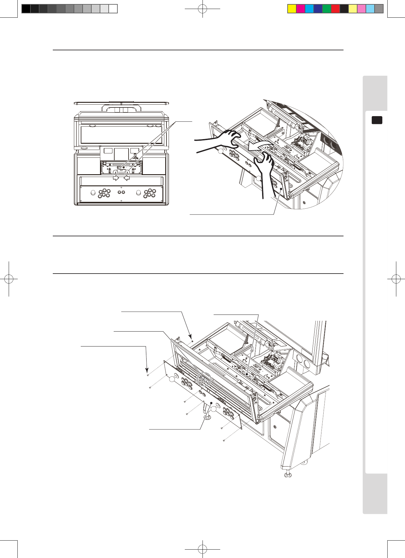
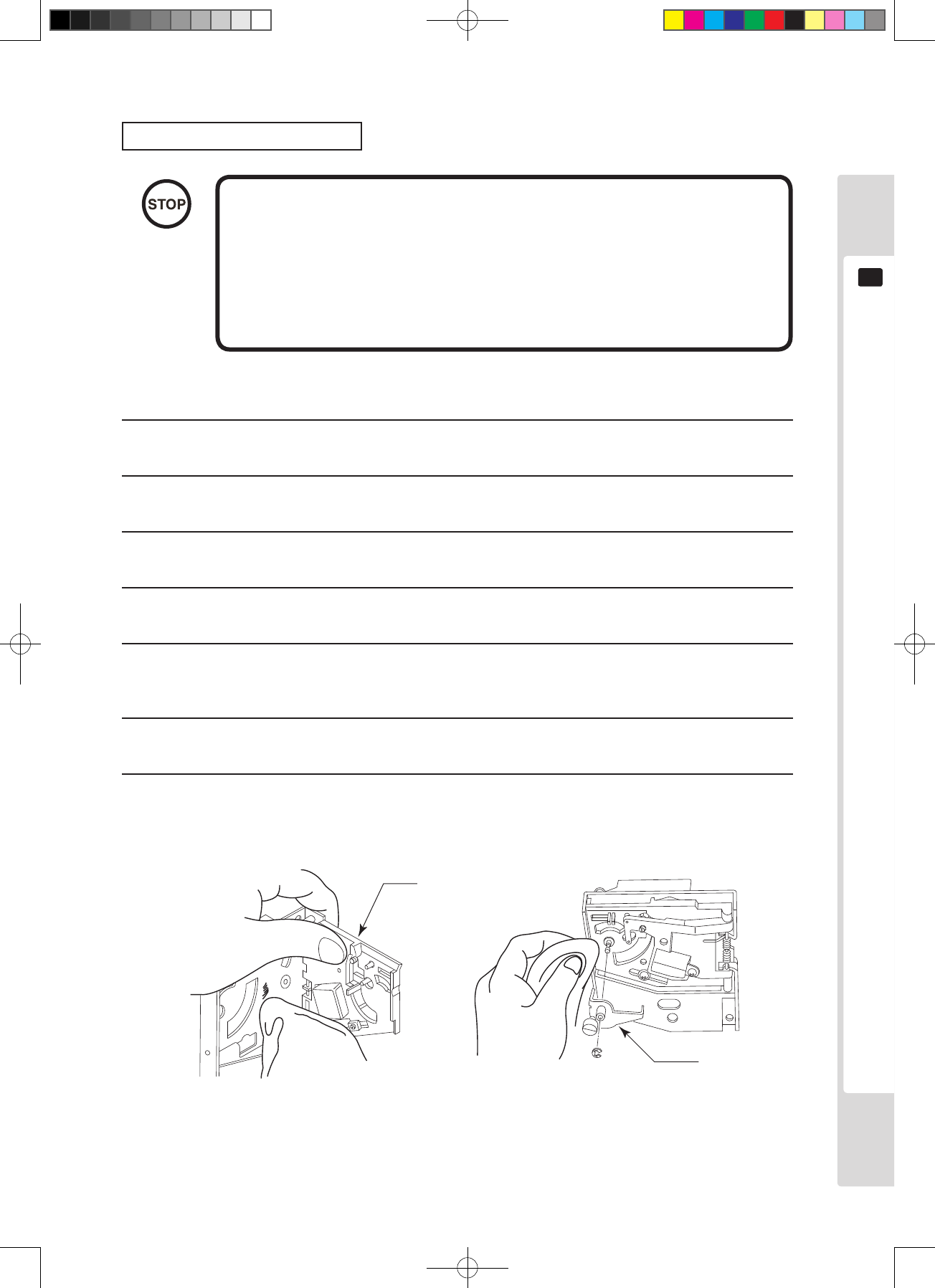
3
Press the tabs together and open the control box upper cover.
* The control box upper cover can close unexpectedly under its own weight, potentially trapping ngers.
Secure the control box upper cover in the raised position before proceeding with the operation described
below.
Figure 9.1b
4
There are nine connectors on the connector panel inside the control box. Disconnect all nine connectors.
In some cases, some of the connectors may already be disconnected, depending on the game used.
5
Remove six pairs of carriage bolts and ange nuts, then remove the control panel. Take care not to damage
the wiring at this stage.
Figure 9.1c
Control box upper cover
Tabs
Control panel
Extract connector
Carriage bolts x 6
M4 x 16
flange nuts x 6
M4
Connector panel
Lindburg.indb 21 2/16/2007 19:12:18
22
For mounting the control panel
9
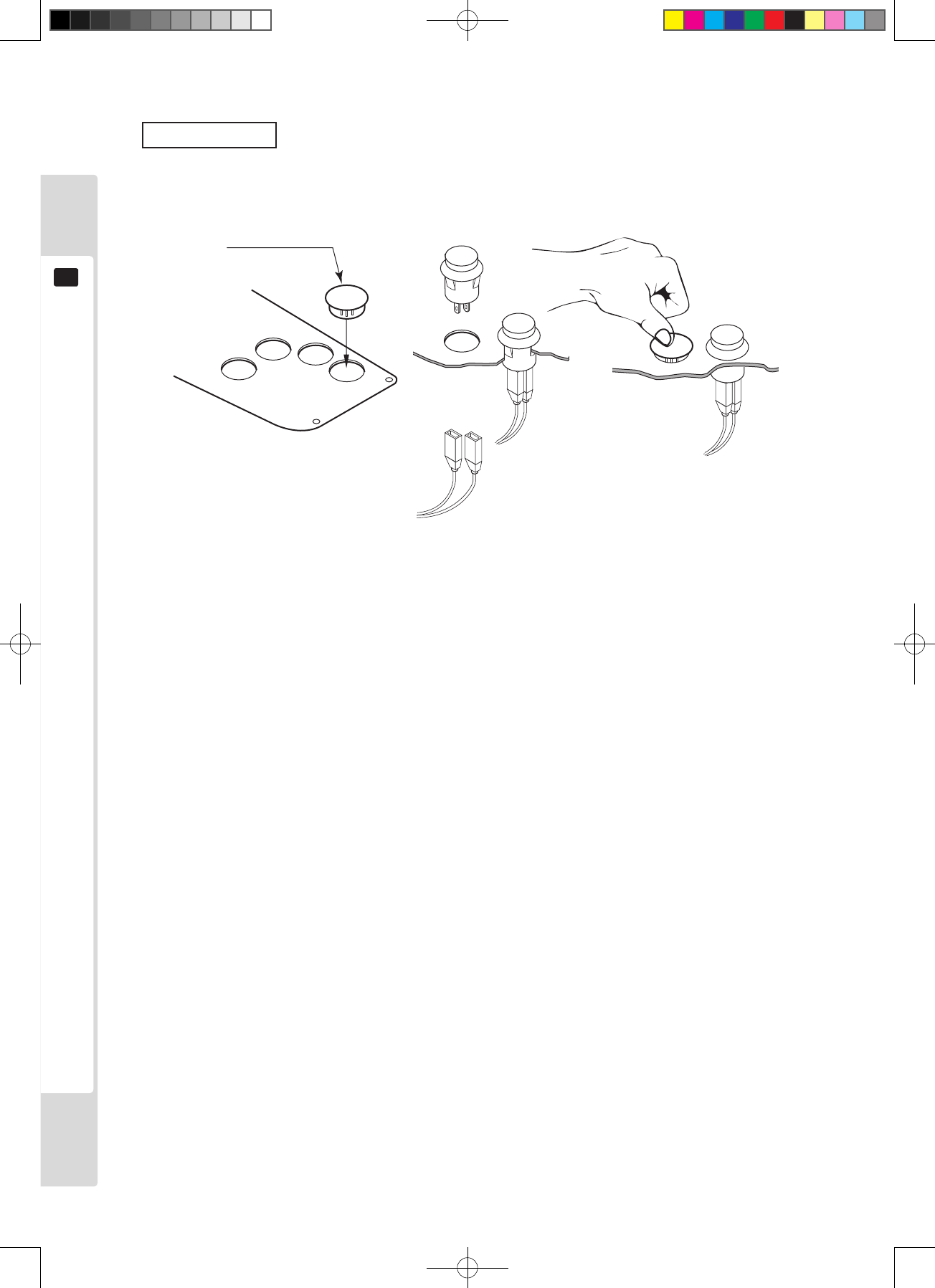
Switch caps
When converting to a game with fewer control buttons, remove the buttons from the control panel and t switch
caps into the empty button holes.
Switch caps
253-5442
Figure 9.1d
Lindburg.indb 22 2/16/2007 19:12:19
For mounting the control panel
23
9
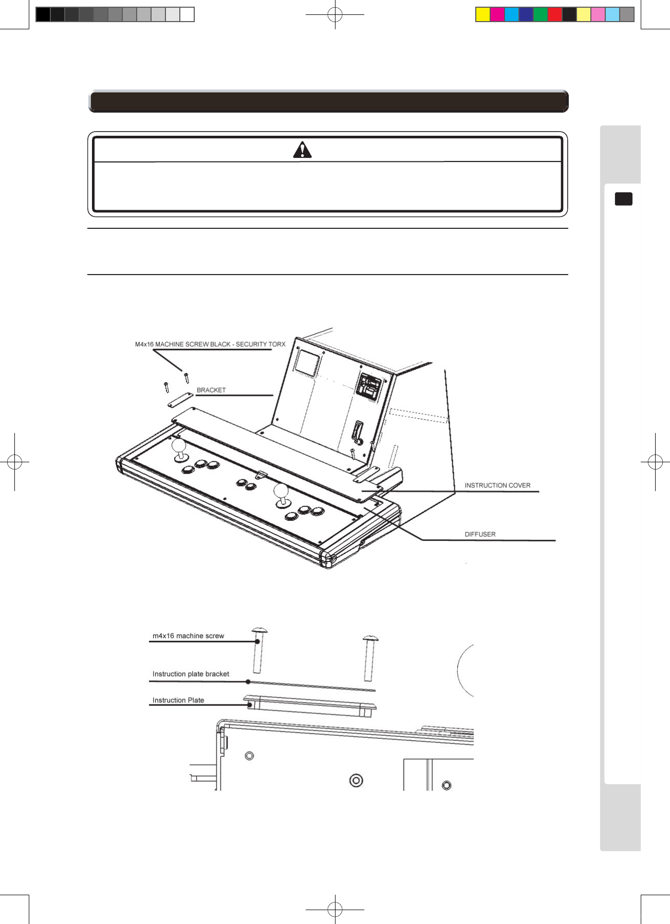
1
Open the control box upper cover, with reference to steps 1-3 in “9-1”.
Take care not to hit or apply excessive force to glass components. Careless
handling can break glass components, and fragments can cause injury.
2
Remove the four screws from the back of the control box upper cover, then remove the two brackets, the
instruction cover and the instruction sheet. The instruction sheet can be replaced.
Figure 9.2a
Figure 9.2b
NOTE
9-2 Replacing the instruction sheet
Lindburg.indb 23 2/16/2007 19:12:20
24
Coin selector
10
● Always turn the power switch off before working on the machine. Electric shocks
or short-circuit accidents could result.
● Take care not to damage the wiring. Electric shocks or short-circuit accidents
could result from damaged wiring.
Coin selector
10
Removing the coin selector
When the entry lid is open, the coin selector is behind it, on the right side. The selector stopper is behind the selector.
Remove it to tilt the selector and pull it out upwards.
Stopper
Coin selecter
Figure 10a
Repairing coin jams
If pressing the coin return button does not return the coin, open the entry lid and then open the coin selector gate.
Remove any jammed coins, then insert a normal coin and check that the selector works normally.
WARNING
Lindburg.indb 24 2/16/2007 19:12:20
Coin selector
25
10
Cleaning the coin selector
● Moisten a soft cloth with water or diluted neutral cleaner, and wring
it out rmly before using it for cleaning.
● Never use machine oil etc. on the coin selector.
● After cleaning the coin selector, insert a standard coin under
normal usage conditions and check that the selector works
normally.
Clean the coin selector every three months. Follow the procedure below to clean it.
1
Turn off the game power supply. Open the entry lid.
2
Remove the coin selector from inside.
3
Open the gate and use a soft brush to brush dirt out.
4
Moisten a soft cloth with water or diluted neutral cleaner, and wring it out rmly before using it for wiping.
5
Remove the cradle.
When removing the retaining ring (E ring), take care not to bend the shaft.
6
Use a soft cloth etc. to wipe dirt off the shaft and bearing.
7
After wiping, blow air onto the coin selector to dry it completely.
Gate
Cradle
Figure 10b Figure 10b
IMPORTANT
Lindburg.indb 25 2/16/2007 19:12:21
26
Coin selector
10
Coin insertion test
Perform the check below once a month, at the same time as the coin switch test.
□ Did the coin meter count the coin normally?
□ Did the coin fall into the cash box normally?
□ If the coin was inserted with the return button pressed, did it drop out of the coin return slot?
Figure 10d
Coins inserted here
Coins rejected here
Coins counted here
06_10_6942_E.indd 26 2/16/2007 19:33:21
The monitor (LCD display)
27
11
The monitor (LCD display)
11
Extract plug
Extract plug
Extract plug
Extract plug
Disassembly
prohibited
Contact
prohibited
Insertion of foreign
objects prohibited
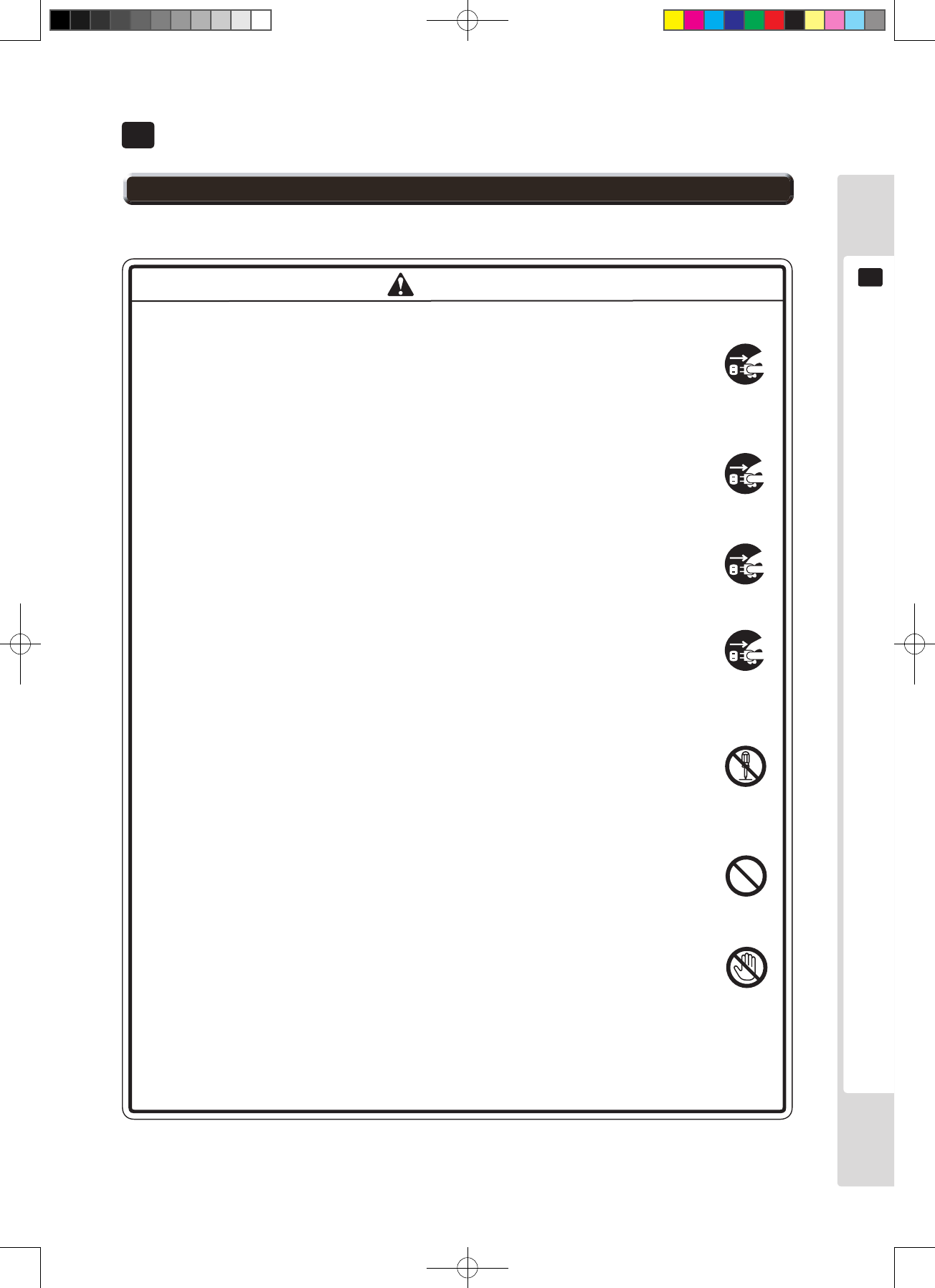
WARNING
11-1 Safety precautions for handling the monitor
Handling malfunctions and breakdowns
● If the machine gives off smoke or an unusual odor, unplug it from the
socket immediately.
Continued use with a damaged power cable could cause re or electric
shock. Check that no further smoke is given off, then contact the
vendor.
● If nothing appears on the screen, unplug the machine from the socket
immediately.
Continued use could cause re or electric shock.
Contact your vendor to arrange an inspection.
● If any liquid or foreign body falls into the interior, unplug the machine
from the socket immediately.
Continued use could cause re or electric shock.
Contact your vendor to arrange an inspection.
● If the machine machine has fallen, or the cabinet has broken, unplug it
from the socket immediately.
Continued use could cause re or electric shock.
Contact your vendor to arrange an inspection.
When using the machine
● Do not attempt to repair, modify or disassemble it.
There are high-voltage components inside which could cause electric
shock or re.
Contact the vendor to arrange internal inspection, adjustment and
repair.
● Foreign objects must not enter the machine.
If metal objects, or ammable materials such as paper, drop into the
interior through the ventilation holes, they could cause electric shocks.
● Do not touch the body of the machine or its power cable during an
electrical storm.
Electric shock accidents could result.
● Be sure to adjust the monitor correctly. Do not operate the monitor with noise
or distortion in the image. An incorrectly adjusted screen image can cause
dizziness, headache or other symptoms in players or other customers.
Lindburg.indb 27 2/16/2007 19:12:23
28
11
The monitor (LCD display)
● Use a dry, soft cloth to wipe dirt off. Do not use coarse gauze or similar materials.
● Alcohol (ethanol) is suitable as a solvent for wiping. Observe the following
restrictions strictly when using detergents.
• Dilute domestic neutral detergent with water, soak it into a soft cloth, and
wring the cloth before using it for wiping.
• Do not use detergents or powders which contain abrasive particles, detergents
containing bleaching agents, or similar cleaners.
• Never use glass cleaners or other alkaline detergents, or solvents such as
thinner.
● Never scrub or scrape the surface with a hard brush or other hard implement.
Clean the screen surface about once a month.
NOTE
11-2 Cleaning the screen surface
Lindburg.indb 28 2/16/2007 19:12:23
The monitor (LCD display)
29
11
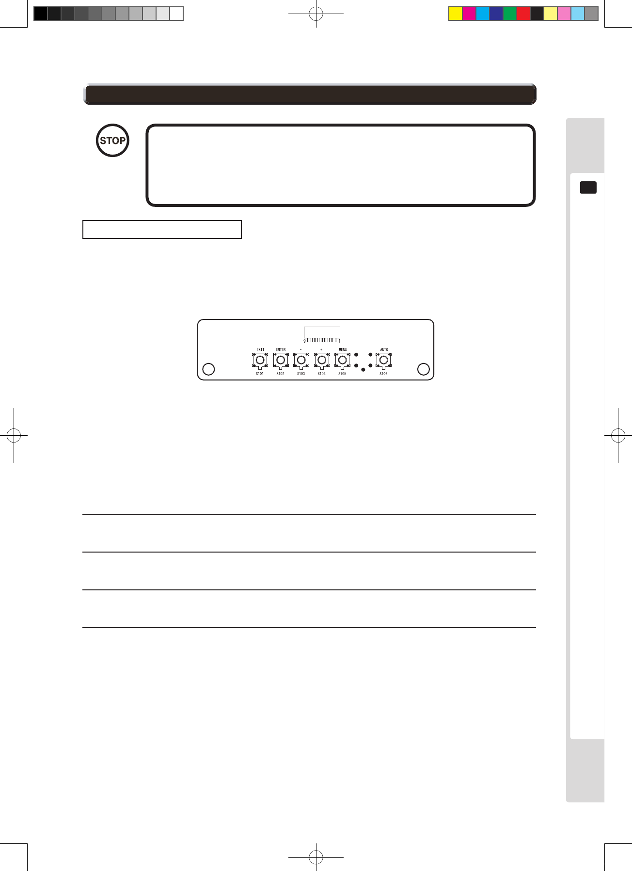
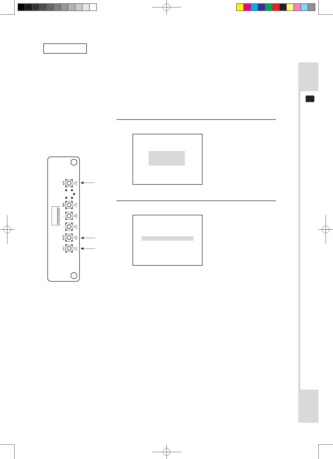
The various adjustment values are adjusted accurately in the factory
before shipping, so do not change them needlessly, or adjust them
other than as specified in this manual. The machine might stop
displaying properly.
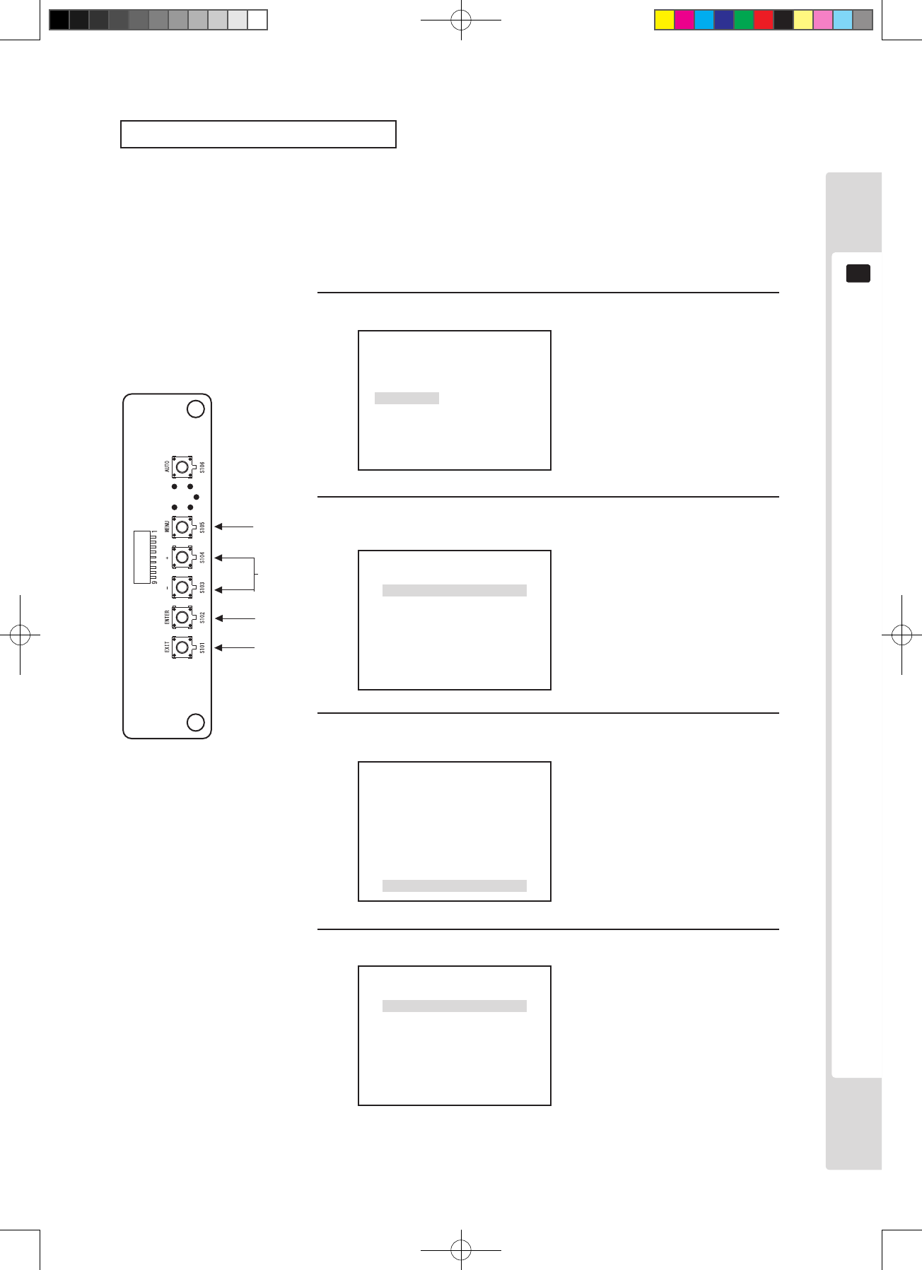
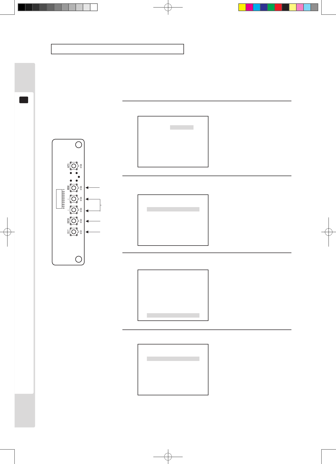
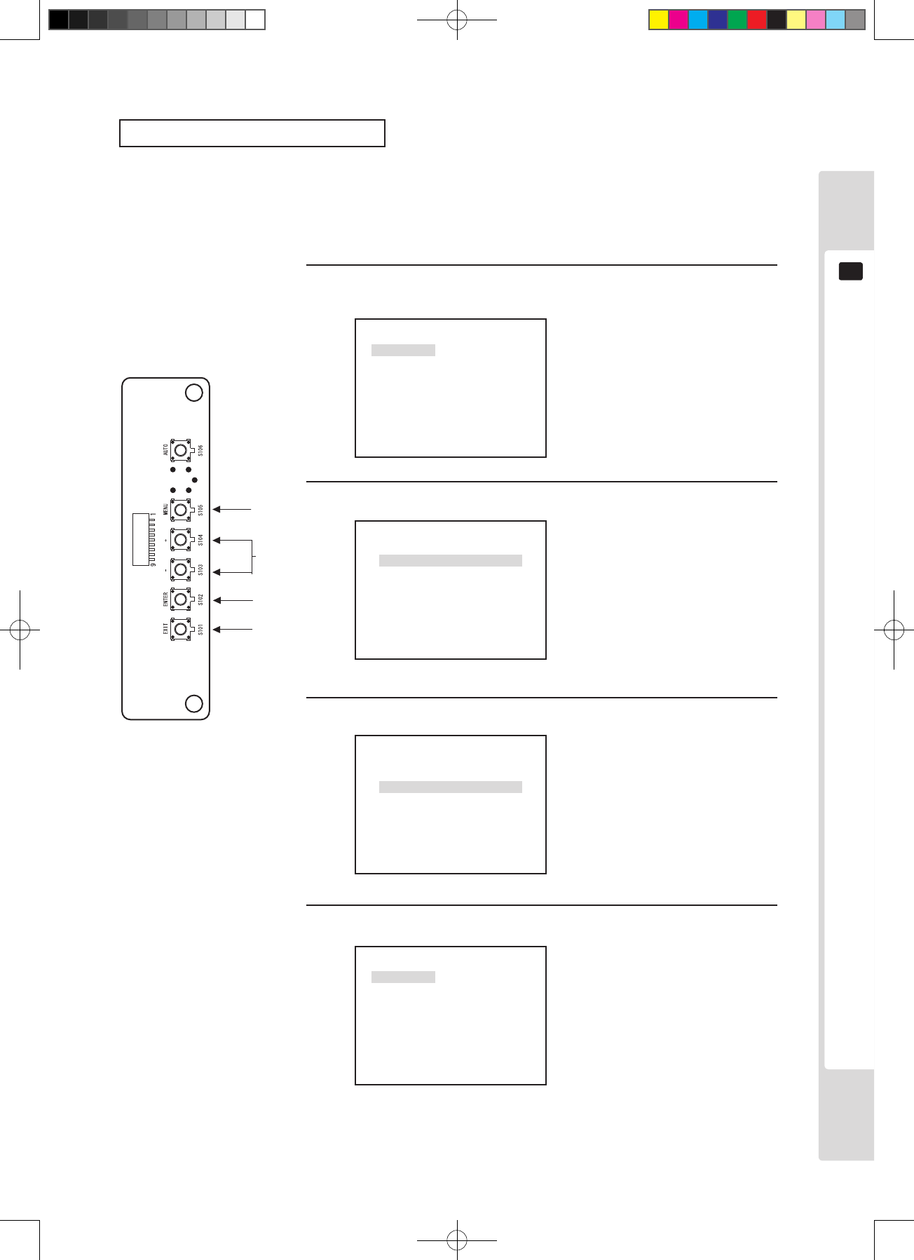
AUTO : Auto setup (automatic adjustment)
MENU : Turn on the Menu display and switch between pages.
+ : Shift the selected menu display/ increase adjustment
values or setting values.
- : Shift the selected menu display/ decrease adjustment
values or setting values.
ENTER : Set the selected menu display/ save adjustment values or
setting values.
EXIT : Close the menu/ cancel adjustment values or setting values.
Operation and adjustment
The basic operation method for using the key switches to make adjustments is explained below.
The monitor adjustment board is visible when the entry lid is open. (See Chapter 8)
Names of parts
monitor adjustment board
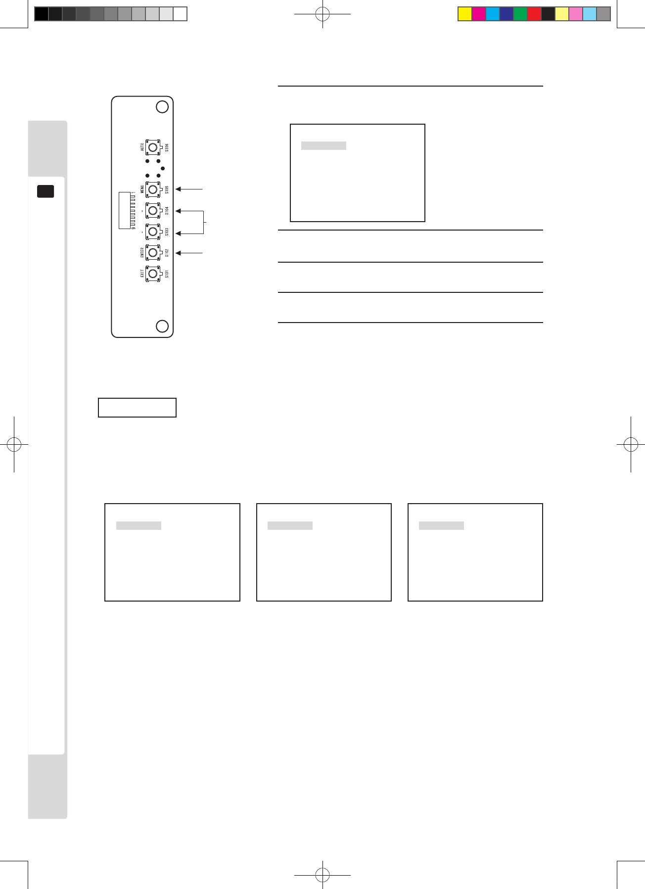
1
To make adjustmentssettings, rst press “MENU” to display the MENU.
2
Next, use the [+] [−] keys to move to the item to adjust/set, then press “ENTER”.
3
Once the item to adjust/set is displayed at the bottom of the screen, use the [+] [−] keys to adjust/set it.
4
Once adjustment/setting is complete, press [ENTER] to store the adjustment/setting values and close.
* To revert to the original values without storing the adjusted/set data, do not press the [ENTER] key, but
press the [EXIT] key to return to the MENU screen.
IMPORTANT
11-3 Monitor adjustment method
Lindburg.indb 29 2/16/2007 19:12:24
30
11
The monitor (LCD display)
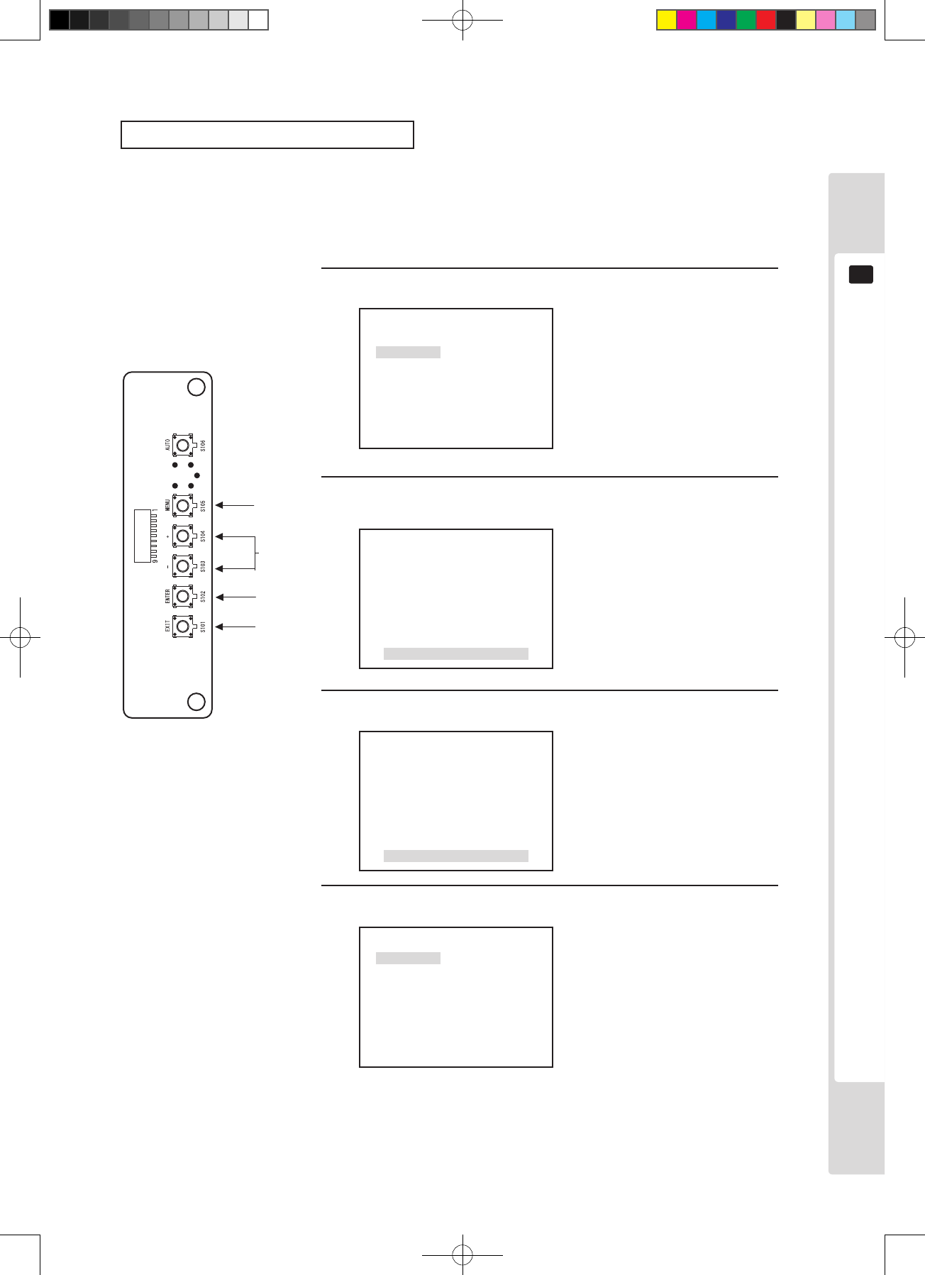
1
2, 4
1
Press the [MENU] key.
P1
W/B
BRIGHT
CONTRAST
SHARPNESS
POSI
CLOCK
PHASE
The MENU is displayed.
2
Use the + and - keys to move to each of adjustment
and setting items.
3
Use the ENTER key to display each of adjustment
and setting items.
4
Use the + and - keys to change each of adjustment
and setting items.
5
Use the ENTER key to store each of adjustment and
setting items.
3, 5
The menu
Care is required, because incorrect operation can change the setup state and prevent correct display.
MENU screen
P1
W/B
BRIGHT
CONTRAST
SHARPNESS
POSI
CLOCK
PHASE
P2
MODE
OSD RESET
TIMING GAME
P2
OSD RESET
TIMING GAME
When input (640x400) (1360x768)
*Pressing the MENU key changes the page.
Lindburg.indb 30 2/16/2007 19:12:24
The monitor (LCD display)
31
11
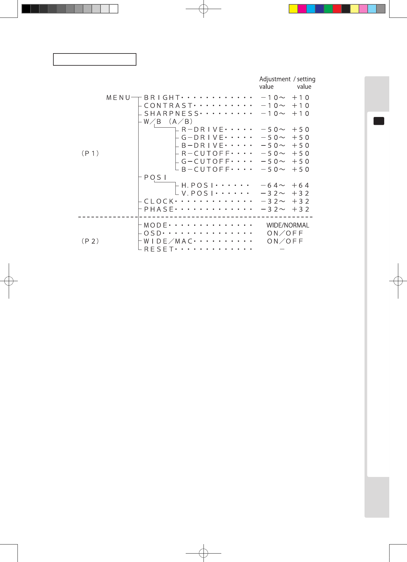
List of setting items
Lindburg.indb 31 2/16/2007 19:12:24

32
11
The monitor (LCD display)
Black level adjustment (BRIGHT)
Black level adjustment (BRIGHT) is performed in the factory to a standard condition, but it can be adjusted for
preference. Changing the brightness of the screen changes the prominence of black areas of the screen.
However, incorrect adjustment of the black level dramatically reduces screen image quality, so the user is advised to
keep the standard settings.
1
3
1
P1
W/B
BRIGHT
CONTRAST
SHARPNESS
POSI
CLOCK
PHASE
2
Press the [MENU] key.
The cursor is at the [BRIGHT] position, so press the [ENTER] key
to display the adjustment and setting item menu.
The MENU screen is displayed.
BRIGHT 0
The adjustment and setting item
menu is displayed.
3
Use the [+] and [-] keys to adjust.
BRIGHT +1
Adjusted data values change.
Adjust the screen contrast
(CONTRAST) to the desired state.
4
Press the [ENTER] key. (Store and close)
The adjusted data is stored and the
display returns to the Menu screen.
*If there is no need to store,
press the [EXIT] key to return to
the Menu screen without storing.
P1
W/B
BRIGHT
CONTRAST
SHARPNESS
POSI
CLOCK
PHASE
2, 4
*4
Lindburg.indb 32 2/16/2007 19:12:25
The monitor (LCD display)
33
11
Contrast adjustment (CONTRAST)
Screen contrast (CONTRAST) is performed in the factory to a standard condition, but it can be adjusted for
preference. Changing contrast alters the level of shading (contrast) in the screen image.
1
1, 3
1
P1
W/B
BRIGHT
CONTRAST
SHARPNESS
POSI
CLOCK
PHASE
2
Press the [MENU] key, then use the [–] key to move the cursor.
Move to the CONTRAST position and press the [ENTER] key.
The adjustment and setting items are displayed.
The MENU screen is displayed.
COTNRAST 0
The adjustment and setting item
menu is displayed.
3
Use the [+] and [–] keys to adjust.
BRIGHT +1
Adjusted data values change.
Adjust the screen contrast
(CONTRAST) to the desired state.
4
Press the [ENTER] key. (Store and close)
The adjusted data is stored and
the display returns to the Menu
screen.
*If there is no need to store,
press the [EXIT] key to return to
the Menu screen without storing.
P1
W/B
BRIGHT
CONTRAST
SHARPNESS
POSI
CLOCK
PHASE
2, 4
*4
Lindburg.indb 33 2/16/2007 19:12:25

34
11
The monitor (LCD display)
Sharpness adjustment (SHARPNESS)
Screen contrast (CONTRAST) is performed in the factory to a standard condition, but it can be adjusted for
preference. Adjusting sharpness alters the level of emphasis on boundaries in the image.
1
1, 3
1
P1
W/B
BRIGHT
CONTRAST
SHARPNESS
POSI
CLOCK
PHASE
2
Press the [MENU] key, then use the [–] key to move the cursor.
Move to the SHARPNESS position and press the [ENTER] key.
The MENU screen is displayed.
SHARPNESS 0
The adjustment and setting items
are displayed.
3
Use the [+] and [–] keys to adjust.
SHARPNESS +1
Adjusted data values change.
Adjust the screen SHARPNESS
to the desired state.
4
Press the [ENTER] key. (Store and close)
The adjusted data is stored and
the display returns to the Menu
screen.
*If there is no need to store,
press the [EXIT] key to return to
the Menu screen without storing.
P1
W/B
BRIGHT
CONTRAST
SHARPNESS
POSI
CLOCK
PHASE
2, 4
*4
Lindburg.indb 34 2/16/2007 19:12:25
The monitor (LCD display)
35
11
White balance adjustment (W/B)
Screen white balance (W/B) is performed in the factory to a standard condition, but it can be adjusted for preference.
However, incorrect adjustment of the white balance dramatically reduces screen image quality, so the user is advised
to keep the standard settings.
1
1, 3
1
P1
W/B
BRIGHT
CONTRAST
SHARPNESS
POSI
CLOCK
PHASE
2
Press the [MENU] key, then use the [–] key to move the cursor.
Move to the W/B position and press the [ENTER] key.
The adjustment and setting items are displayed.
The MENU screen is displayed.
B-CUTOFF 0
G-CUTOFF 0
R-CUTOFF 0
B-DRIVE 0
G-DRIVE 0
R-DRIVE 0
W/B The adjustment and setting item
menu is displayed.
3
R-DRIVE +1
Adjusted data values change.
Adjust the screen white balance
(W/B) to the desired state.
4
Press the [ENTER] key. (Store and close)
The adjusted data is stored and
the display returns to the Menu
screen.
*If there is no need to store,
press the [EXIT] key to return to
the Menu screen without storing.
2, 3, 4
*4
Select the item to adjust and press the [ENTER] key,
then adjust with the [+] and [–] keys.
B-CUTOFF 0
G-CUTOFF 0
R-CUTOFF 0
B-DRIVE 0
G-DRIVE 0
R-DRIVE 0
W/B
Lindburg.indb 35 2/16/2007 19:12:25
36
11
The monitor (LCD display)
Adjustment of screen display image (POSI)
Screen display position (POSI) is adjusted in the factory to a standard condition, but it can be adjusted
for preference. In some cases, it may be necessary to make adjustments after changing game software.
1
1, 3
1
P1
W/B
BRIGHT
CONTRAST
SHARPNESS
POSI
CLOCK
PHASE
2
Press the [MENU] key, then use the [+] key to move the cursor.
Move to the POSI position and press the [ENTER] key.
The adjustment and setting items are displayed.
The MENU screen is displayed.
The adjustment and setting item
menu is displayed.
3
H.POSI +1
Adjusted data values change.
Adjust the screen position (POSI)
to the desired state.
4
Press the [ENTER] key. (Store and close)
The adjusted data is stored and
the display returns to the Menu
screen.
*If there is no need to store,
press the [EXIT] key to return to
the Menu screen without storing.
2, 3, 4
*4
V.POSI 0
H.POSI 0
POSI
Select the item to adjust and press the [ENTER] key,
then adjust with the [+] and [–] keys.
V.POSI 0
H.POSI 0
POSI
Lindburg.indb 36 2/16/2007 19:12:26

The monitor (LCD display)
37
11
Clock adjustment (CLOCK)
The screen sampling clock (CLOCK) is adjusted in the factory to a standard condition, but it can be adjusted for
preference. In some cases, it may be necessary to make adjustments after changing game software.
However, incorrect clock adjustment dramatically reduces screen image quality, causing jittering and moire patterns,
so the user is advised to keep the standard settings.
1
1, 3
1
P1
W/B
BRIGHT
CONTRAST
SHARPNESS
POSI
CLOCK
PHASE
2
Press the [MENU] key, then use the [–] key to move the cursor.
Move to the CLOCK position and press the [ENTER] key.
The adjustment and setting items are displayed.
The MENU screen is displayed.
The adjustment and setting item
menu is displayed.
3
CLOCK +1
Adjusted data values change.
Adjust so that the sampling clock
is in the optimum state. (so that
jitter and moire effects disappear)
4
Press the [ENTER] key. (Store and close)
The adjusted data is stored and
the display returns to the Menu
screen.
*If there is no need to store,
press the [EXIT] key to return to
the Menu screen without storing.
2, 4
*4
Use the [+] and [–] keys to adjust.
CLOCK 0
P1
W/B
BRIGHT
CONTRAST
SHARPNESS
POSI
CLOCK
PHASE
Lindburg.indb 37 2/16/2007 19:12:26

38
11
The monitor (LCD display)
Phase adjustment (PHASE)
The screen sampling phase (PHASE) is adjusted in the factory to a standard condition, but it can be adjusted for
preference. In some cases, it may be necessary to make adjustments after changing game software.
However, incorrect phase adjustment dramatically reduces screen image quality, causing jittering, so the user is
advised to keep the standard settings.
1
1, 3
1
P1
W/B
BRIGHT
CONTRAST
SHARPNESS
POSI
CLOCK
PHASE
2
Press the [MENU] key, then use the [–] key to move the cursor.
Move to the PHASE position and press the [ENTER] key.
The adjustment and setting items are displayed.
The MENU screen is displayed.
The adjustment and setting item
menu is displayed.
3
PHASE +1
Adjusted data values change.
Adjust so that the sampling phase
is in the optimum state.
(Jitter disappears)
4
Press the [ENTER] key. (Store and close)
The adjusted data is stored and
the display returns to the Menu
screen.
*If there is no need to store,
press the [EXIT] key to return to
the Menu screen without storing.
2, 4
*4
Use the [+] and [–] keys to adjust.
PHASE 0
P1
W/B
BRIGHT
CONTRAST
SHARPNESS
POSI
CLOCK
PHASE
Lindburg.indb 38 2/16/2007 19:12:26
The monitor (LCD display)
39
11
Aspect ratio switching (MODE)
The aspect ratio of the screen can be switched. When WIDE is used, the display lls the entire screen, but when
NORMAL is used, the screen display is the maximum size possible at the aspect ratio of the input signal.
However, this is not the case when input at 640 x 400, 1,360 x 768 or 1,280 x 720 is used.
P2
MODE
OSD RESET
1
3
1
2
MODE MENU is displayed.
The MENU P2 screen is
displayed.
The adjustment and setting item
menu is displayed.
3
The display screen changes
when the setting value changes.
4
Press the [ENTER] key. (Store and close)
The adjusted data is stored and
the display returns to the Menu
screen.
*If there is no need to store,
press the [EXIT] key to return to
the Menu screen without storing.
1, 4
*4
Use the [+] and [–] keys to adjust.
Press the [MENU] key twice, then press the [ENTER] key at the
MODE position.
NORMAL
WIDE
MODE
NORMAL
WIDE
MODE
P2
MODE
OSD RESET
Lindburg.indb 39 2/16/2007 19:12:27
40
11
The monitor (LCD display)
Adjust setting values for BRIGHT, CONTRAST, W/B, SHARPNESS, POSI, CLOCK, PHASE, MODE, OSD and
WIDE/MAC/to the factory defaults.
On-screen display (OSD)
ON: Always display the OSD corresponding to (ANALOG/DIGITAL).
OFF: Only display when the above input is changed.
Notes: In case of No Input Signal or Out of Range, the OSD is displayed continuously while the condition
persists, regardless of whether the setting is on or off.
Input signal identication (WIDE/MAC)
PCinput.
ON: Only enabled with input is VGA-TEXT (720x400)/MAC13/MAC16/MAC19/MAC21/WVGA/WSVGA/
WXGA/720p.
OFF: Identication of WID/MAC-type signals is OFF
Reset (RESET)
Lindburg.indb 40 2/16/2007 19:12:27
The monitor (LCD display)
41
11
Auto setup
When auto setup is performed, signal timing is identified automatically, and the items below are automatically
adjusted to their optimum values/stored.
• Sampling frequency/phase • Horizontal/vertical display position
Memory can hold up to 136 settings in the user area, so once the number of settings exceeds 136, they will be
overwritten sequentially.
1
1
STRAT:ENTER KEY
QUIT:EXIT KEY
2
Press the [AUTO] key.
Press the [ENTER] key.
The setting screen is displayed.
Auto setup is performed.
*Press the [EXIT] key to avoid
executing.
2
*2
AUTO IN PROGRESS
Lindburg.indb 41 2/16/2007 19:12:27
42
11
The monitor (LCD display)
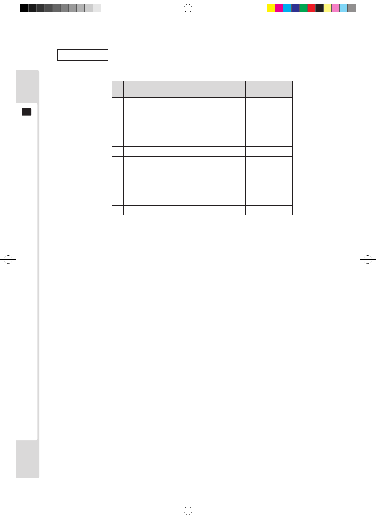
Input signal
No. Input signal name
Horizontal frequency
Vertical frequency
1
2
3
4
5
6
7
8
9
10
11
12
(640x400)
(640x480):VESA
(640x480):NAOMI
(640x480):TRIFORCE
(640x480):CHIHIRO
(800x480)
(800x600)
(1024x600)
(1024x768)
(1280x768)
(1280x1024)
(1360x768)
31.46
[kHz] [Hz]
70.07
31.38 59.77
31.69 59.79
31.47 59.94
31.47 59.94
29.77 59.54
37.95 60.43
37.51 60.12
48.34 59.97
47.92 60.05
63.98 60.02
47.51 59.53
Lindburg.indb 42 2/16/2007 19:12:27
Replacing the uorescent lamp
43
12
Replacing the uorescent lamp
12
● Always turn the power off before working on the machine. Working with the
power switched on could lead to electric shocks or short-circuit accidents.
● Touching a hot uorescent tube could cause a burn. Take care when replacing
the tube.
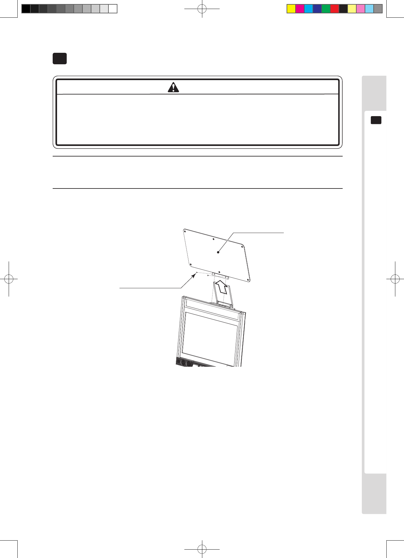
1
Use the main switch of the AC unit or the sub-power switch behind the service door to turn the power supply
off.
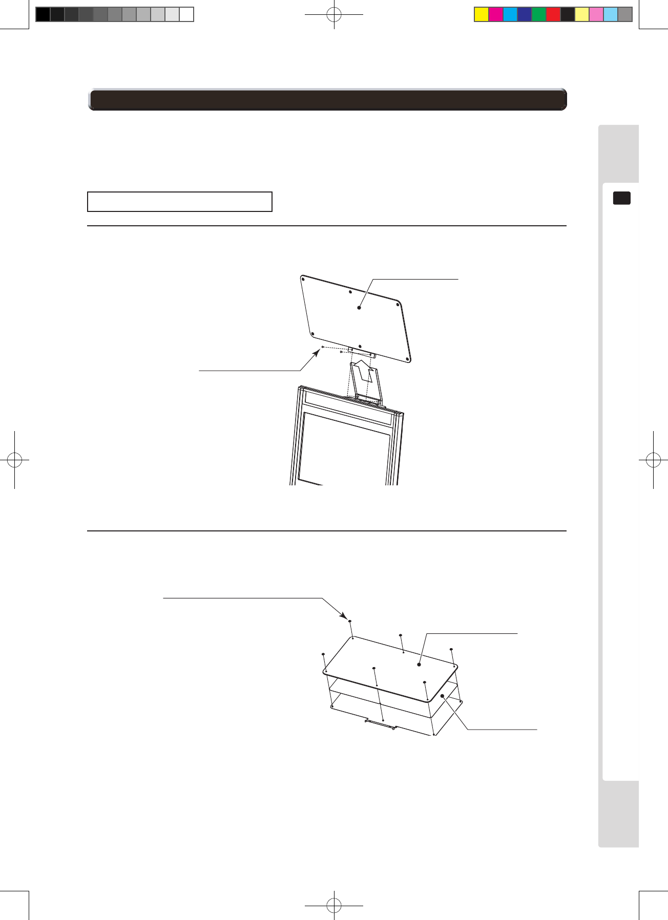
2
Remove the two truss screws and lift the billboard assembly up to remove it.
Billboard assembly
Truss screw (black) x 2
M4 x 8
Figure 12a
WARNING
Lindburg.indb 43 2/16/2007 19:12:28
44
Replacing the uorescent lamp
12
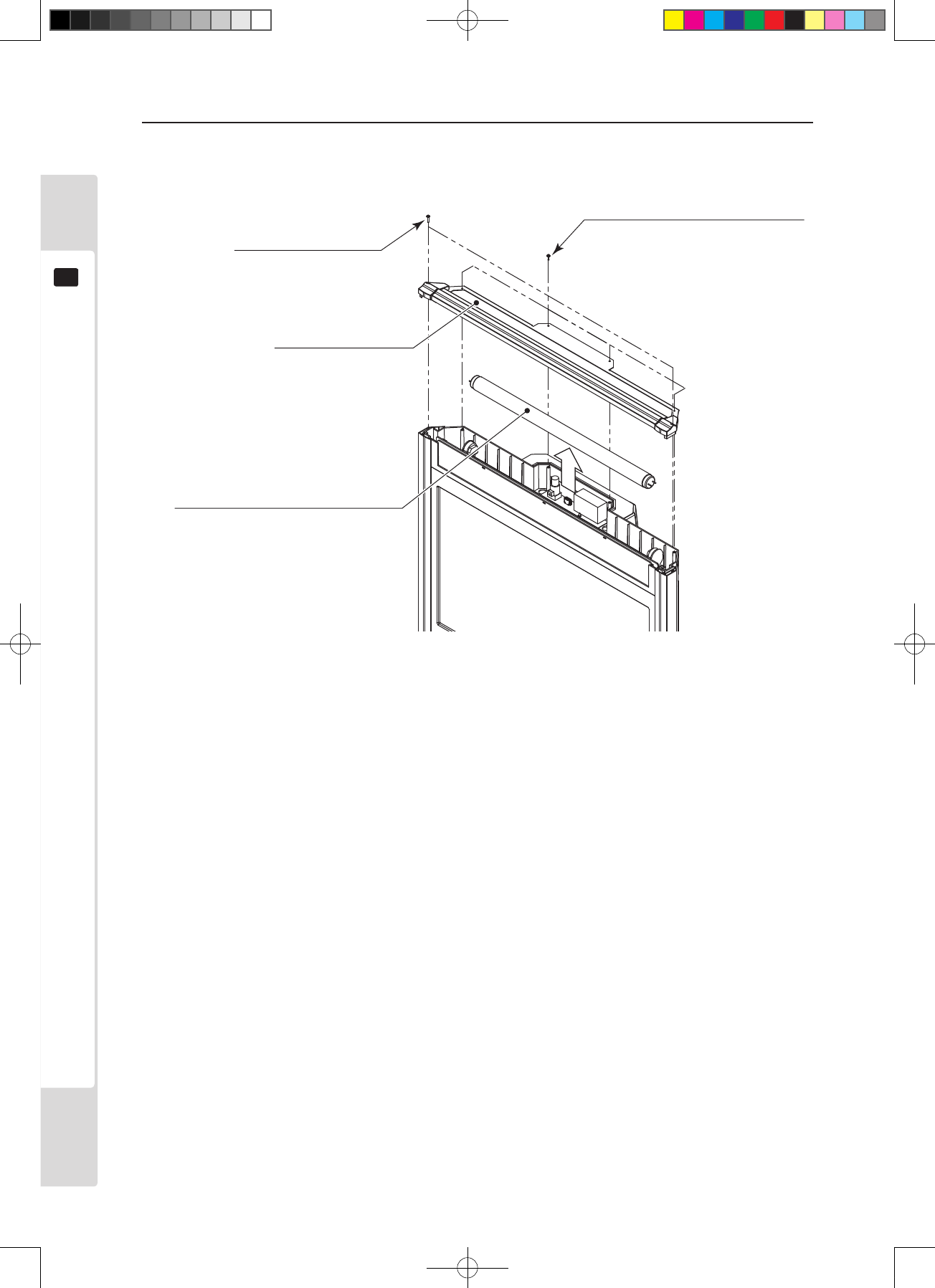
3
Remove the 6screws and the light box lid assembly to replace the uorescent lamp.
Figure 12b
S-tight screw x 2
M3 x 16, with flat washer
Light box lid assembly
FL TUBE
18W T8 600MM (390-0100-18DUK)
ASSY FL TRAY
LCB 100V 18W (390-0100-18XUK)
Screw (black) x 4
M3 x 12, with flat and spring washer
Lindburg.indb 44 2/16/2007 19:12:28
Replacing the game board
45
13
Replacing the game board
13
● Be sure to turn the power off before touching the inside of the machine, to
prevent electric shock accidents.
● Take care not to damage the wiring. Electric shocks or short-circuit accidents
could result from damaged wiring.
● The current capacities for game boards in this product are 3.3V 12A, 5.0V 10A,
12V 2A. Never use game boards which require capacity above these values. Use
of such boards would cause overheating and ignition.
● When changing to a game board that does not follow the JAMMA standard, be
sure to use the dedicated harness specied by the game board manufacturer.
Use of anything other than the specific dedicated wiring risks causing
overheating and re.
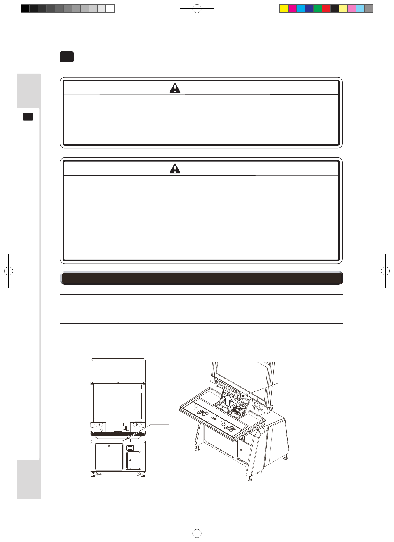
This manual explains how to remove the Lindbergh. Before starting work to change to a different game board,
contact the game board vendor and check it thoroughly.
To remove the game board (Lindbergh), take the entire base (wooden board), on which the game board is mounted,
out of the cabinet.
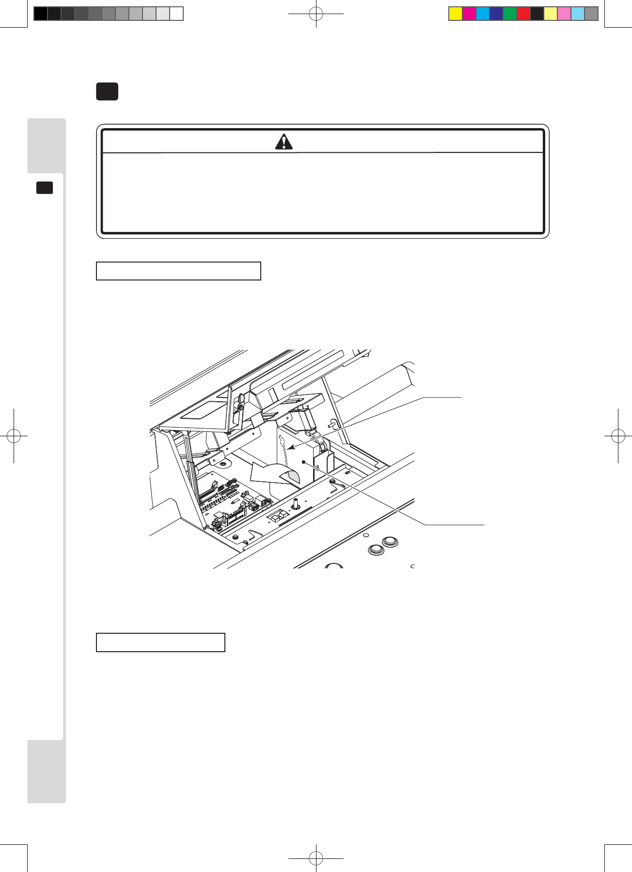
1
Use the main switch of the AC unit or the sub-power switch behind the service door to turn the power supply
off. Loosen the anti-unlocking screw to unlock the service door.
2
Remove all the connectors which are connected to the game board. Also remove all other connectors on the
base that connect to anything other than the game board. The number of connectors varies between games.
Figure 13.1a
Extract connector
WARNING
13-1 How to remove the game board
Lindburg.indb 45 2/16/2007 19:12:30
46
Replacing the game board
13
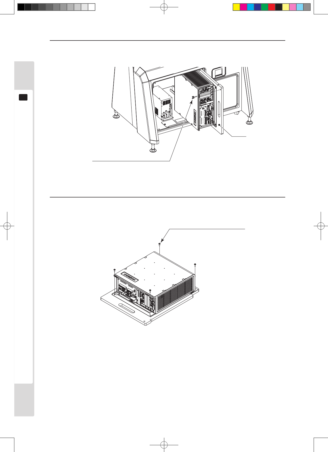
3
Remove the one thumb screw that fastens the base, then remove it from the cabinet, with the game board still
attached.
Figure 13.1b
4
Remove the four screws and take the game board off.
Screw x 4
M4 x 16, with flat and spring washer
Figure 13.1c
Base
Thumb screw x 1
M4 x 25, using flat and spring washer
Lindburg.indb 46 2/16/2007 19:12:32
Replacing the game board
47
13
Replacement may be required for some game titles.
Basically, replace the billboard sheet, the instruction sheet and the sub-instruction sheet.
Refer to “9-2” for replacement of the instruction sheet.
Replacing the billboard sheet
1
Remove the two truss screws and lift the billboard assembly up to remove it.
Billboard assembly
Truss screw (black) x 2
M4 x 8
Figure 13.2a
2
Remove the six Allen screws and the billboard front plate to replace the billboard sheet.
Billboard sheet
Billboard front plate
Allen screw x 6
M4 x 6, using special dished washer
Figure 13.2b
13-2 Replacing the design components
Lindburg.indb 47 2/16/2007 19:12:33
48
Replacing the game board
13
Sub-instruction sheet
Afx the sub-instruction sheet to the entry lid.
Sub-instruction sheet
Figure 13.2c
Lindburg.indb 48 2/16/2007 19:12:34
Replacing the game board
49
13
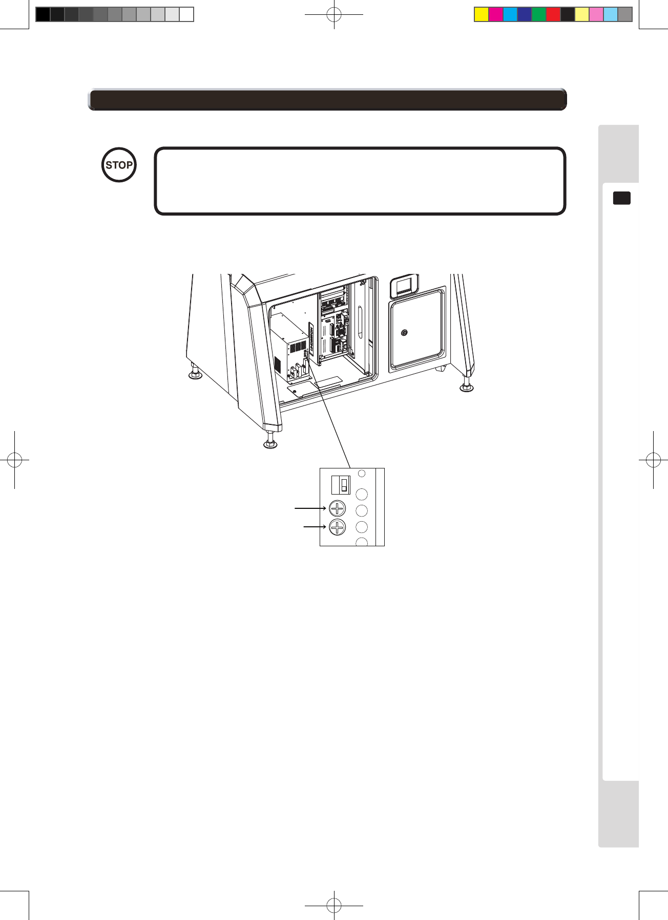
V.ADJ has already been set at the factory. Use it with the factory default
setting. Needless alteration of the setting can damage the IC board and
cause malfunctions.
The power supply unit inside the cabinet has a VR for adjusting game board DC power supply voltage.
Volume for +5V
Volume for +3.3V
Figure 13.3 Power supply unit
IMPORTANT
13-3 The game board power supply voltage adjustment knob
Lindburg.indb 49 2/16/2007 19:12:37
50
Regular inspection list
14
Regular inspection list
14
Perform regular inspection and maintenance of the items below, to maintain the performance of the machine and
ensure the safety of its operation.
The control panel is touched directly by the player’s hands. Clean it as often as necessary, and provide hand wipes
etc. so players can play without worrying about cleanliness.
● Once a year, check that the power cable is undamaged, that the plug is securely
inserted into the socket, and that there is no buildup of dust between the socket
and the plug. Use with a buildup of dust could cause accidents or damage.
● Once a year, contact the vendor or the service contact named in this manual to
order cleaning of the interior of the machine. Leaving dust to accumulate inside
the machine without cleaning can cause re or other accidents. A fee will be
changed for interior cleaning.
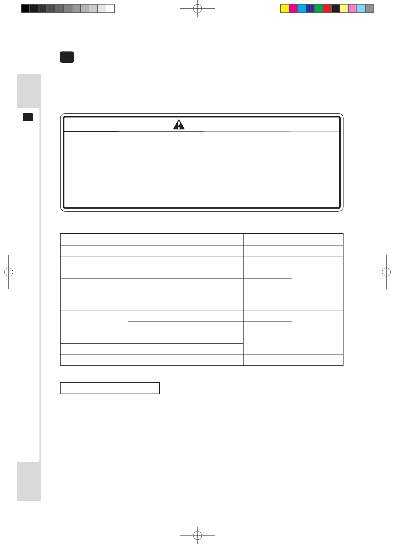
Table 14 Regular inspection list
See the game board
servicing manual
Task Interval Reference item
Cabinet Check that all adjusters touch the ground Daily Ch. 3
Monitor Clean the screen surface Weekly 11-2
(LCD display) Check adjustment Monthly
Game board Check settings Monthly
Control panel Input test Monthly
Speakers and sound Sound test, volume adjustment check Monthly
The coin selector Coin insertion test Monthly Ch. 10
Cleaning Every 3 months
Power plug Inspection, cleaning Yearly As above
Internal Cleaning
Cabinet surfaces Cleaning As required As below
Cleaning cabinet surfaces
If the cabinet is very dirty, wet a soft cloth with water, or with diluted neutral detergent, wring it out and use it to
wipe the cabinet. Do not use solvents such as alcohol, thinner or benzene, or abrasives, bleaches or chemical cloths,
because they may damage the surface nish. Some general home, kitchen or furniture detergents are strong enough
to penetrate plastic components, paints and printing. Before using any detergent, read the precautions carefully, and
test its effects rst on an inconspicuous area.
WARNING
Lindburg.indb 50 2/16/2007 19:12:41
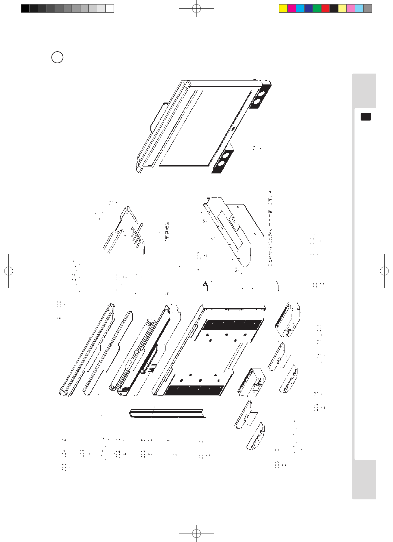
Parts list
51
15
Parts list
15
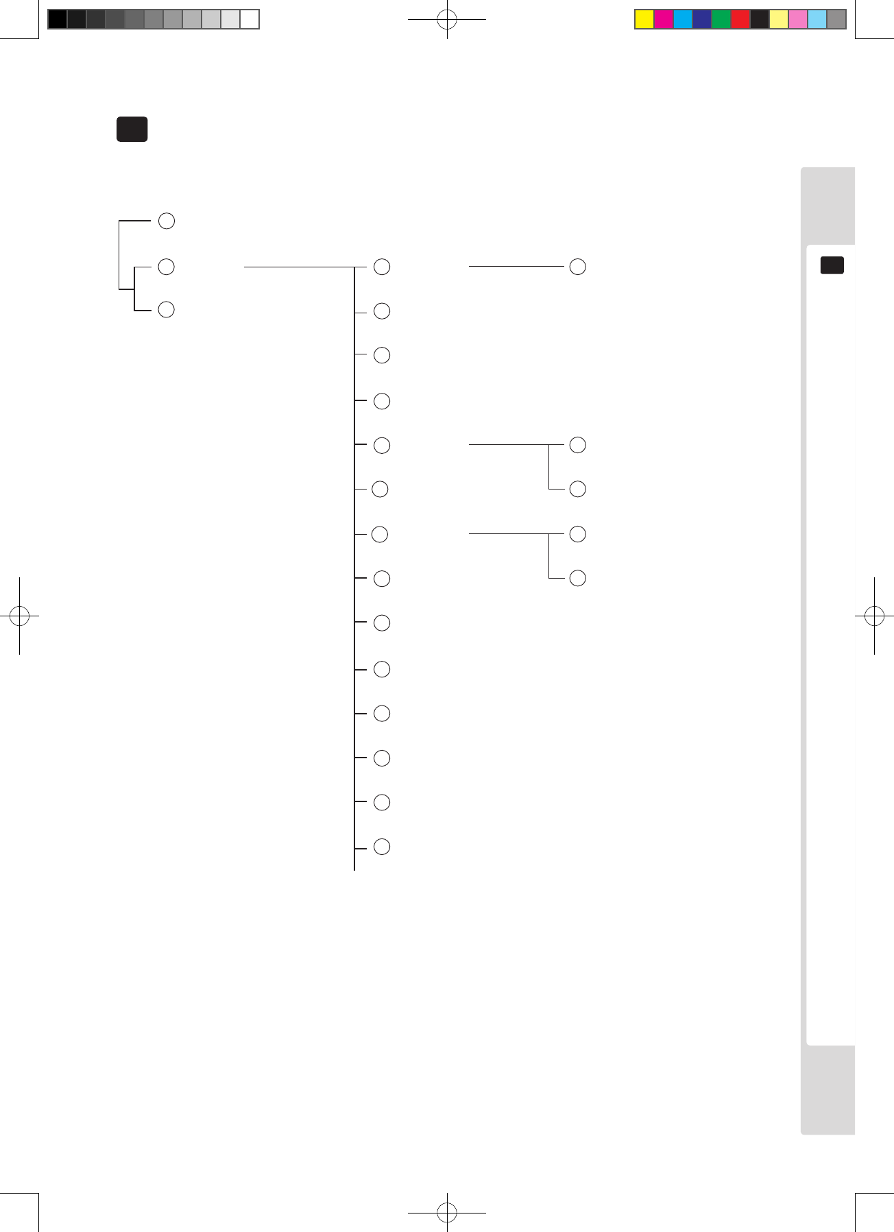
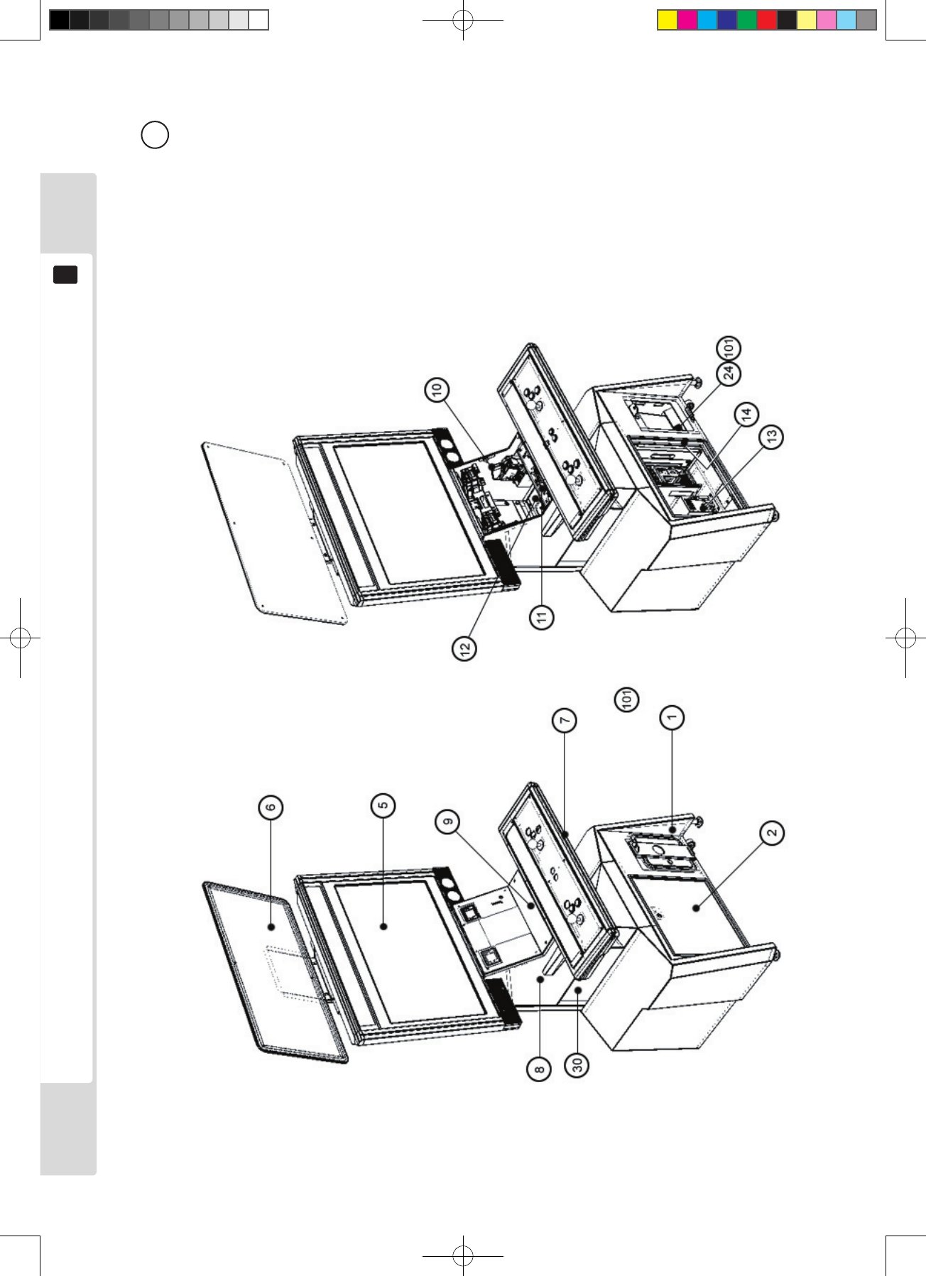
3 LCB-1100UK
ASSY BASE CABINET
5LCB-1270UK
ASSY SERVICE DOOR
6LCB-1300UK
AC UNIT
7LCB-1500UK
ASSY REAR FRAME
8
11
12
LCB-1600UK
ASSY MONITOR 32
LCA-1700UK
ASSY BILLBOARD W/O DESIGN
LCB-2000UK
ASSY CONTROL BOX
15 LCB-2100UK
ASSY ENTRY BOX
16 LCB-2150UK
ASSY ENTRY LID
17 LCB-2170UK
ASSY COIN SELECTOR
18 LCA-2180UK
SW UNIT
19 LCA-2190UK
I/O UNIT
20 LCA-4000UK
ASSY PWR SPLY
21 LCA-4050UK
ASSY SUB ELEC
2 LCB-1000UK
ASSY CABINET UR
1 LCB-00001UK
TOP ASSY LCB UR (VT3)
23 LCB-2500UK
ASSY CONTROL PANEL 2L6B
22 LCB-4300UK
ASSY XFMR
4 LCB-1150UK
ASSY BASE BOX
10 LCA-1660UK
ASSY SPEAKER R
9LCA-1650UK
ASSY SPEAKER L
14 LCA-2060UK
ASSY CONTROL BOX LOWER
13 LCA-2030UK
ASSY CONTROL BOX UPPER
Lindburg.indb 51 2/16/2007 19:12:42
52
Parts list
15
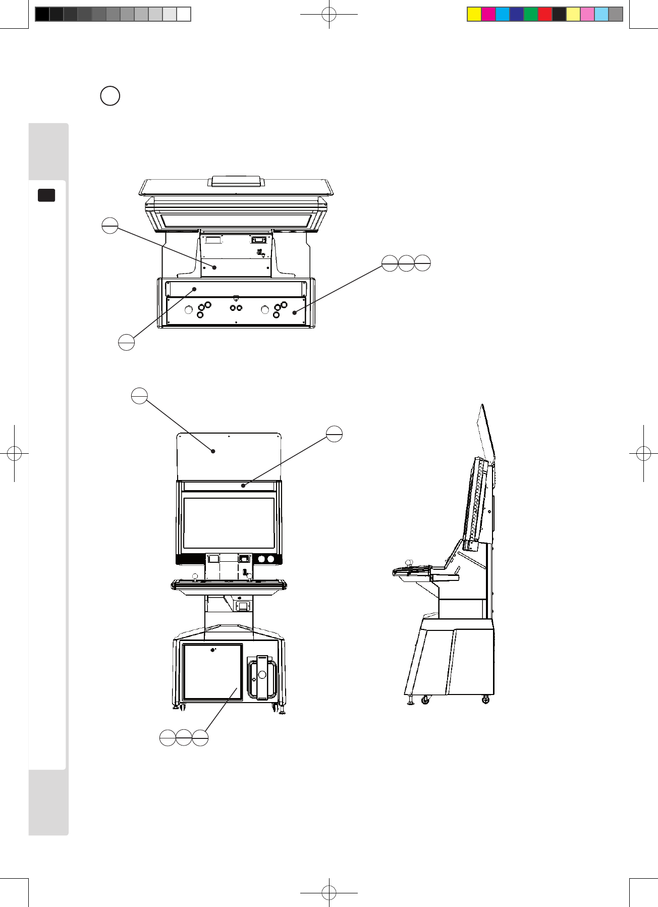
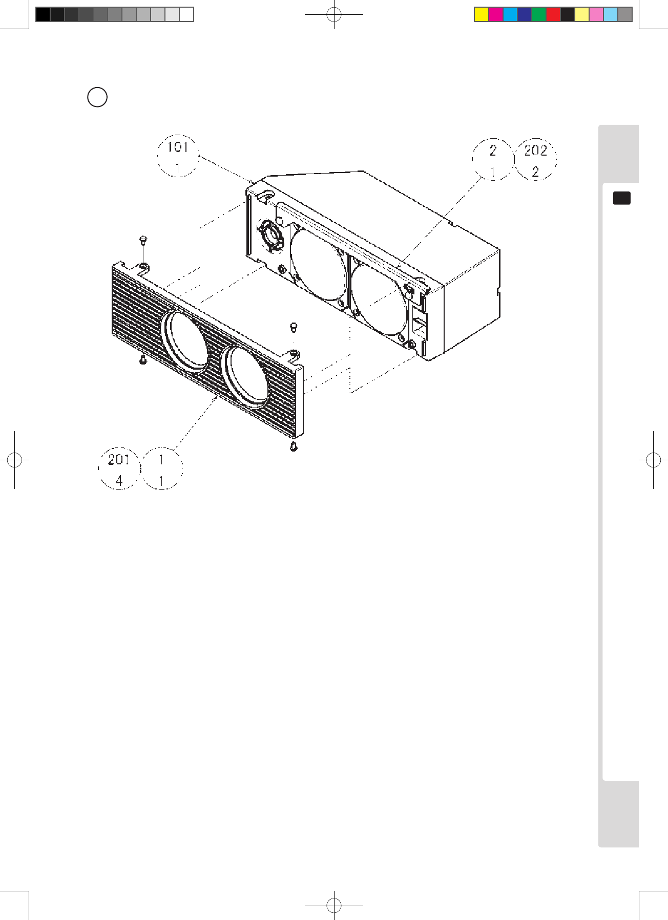
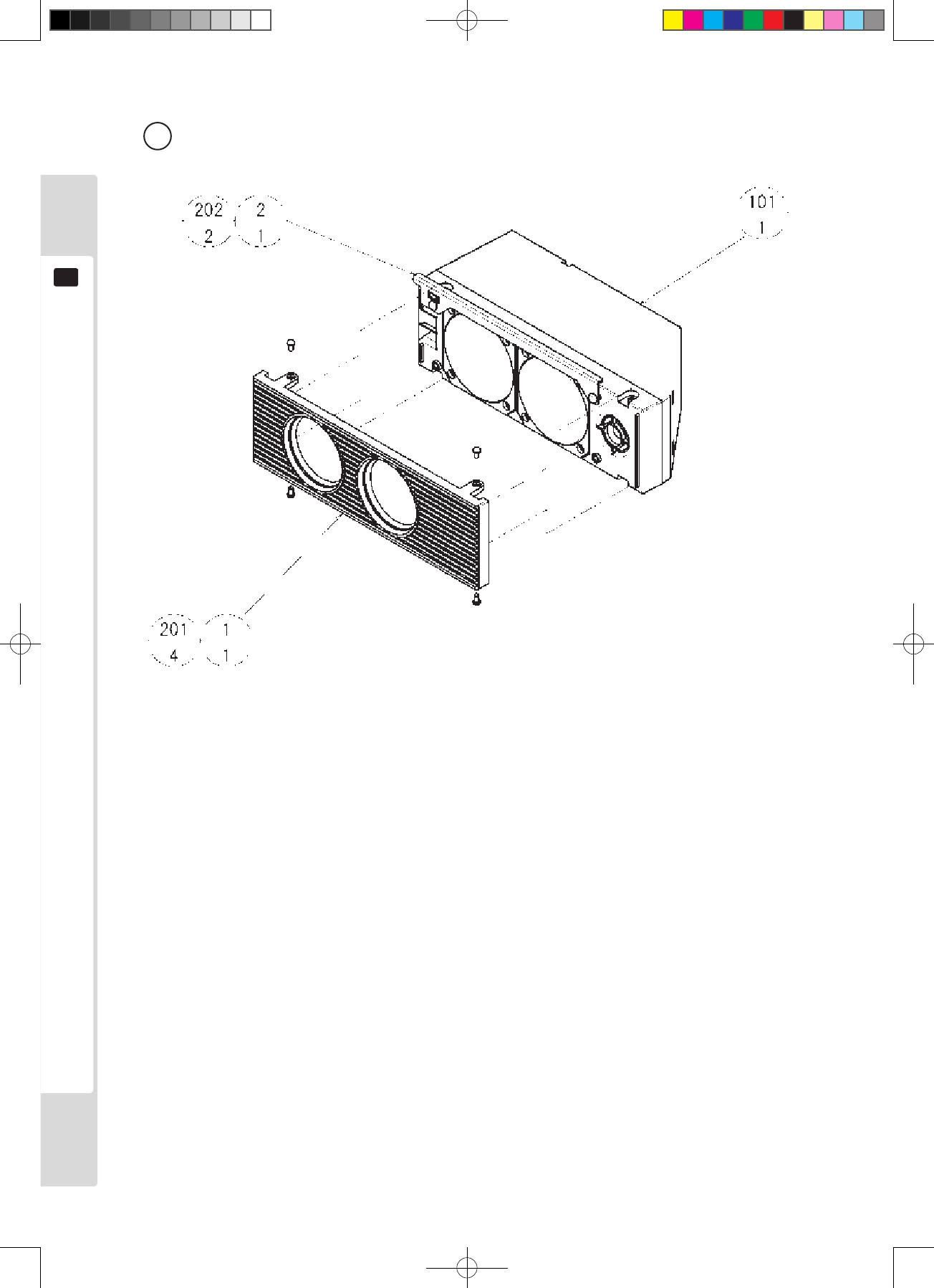
1 TOP ASSY LCB UR (VT3) (LCB-00001UK) (D-1/2)
204 203
1
1
1
4
1
2
6
201
6
202
1
5
1
6
1
1
1
3
Lindburg.indb 52 2/16/2007 19:12:42

Parts list
53
15
ITEM NO. PART NO. DESCRIPTION NOTE
1 LCA-1000UK ASSY CABINET UR
2 LCA-2500UK ASSY CONTROL PANEL 2L6B
3 LCB-0101UK WOODEN BASE MAIN
4 429-0777-01UK BILLBOARD SHEET VT3
5 422-0946U SHEET INSTR VT3
6 LCA-0004 STICKER SUBINSTR LCA
201 031-0S0416 CRG BLT STN M4×16
202 050-F00400 FLG NUT M4
203 032-000425 WING BLT M4×25
204 068-441616 FLT WSHR 4.4-16×1.6
205 060-S00400 SPR WSHR M4
401 253-5442 ANTI BACTERIAL CAP SW
402 LCA-60027 WH DC PWR SPLY FOR JVS BD
403 LCA-60028 WH DC PWR SPLY FOR ATX BD
404 000-P00416-W M SCR PH W/FS M4×16
1 TOP ASSY LCB UR (VT3) (LCB-00001UK) (D-2/2)
Lindburg.indb 53 2/16/2007 19:12:42
54
Parts list
15
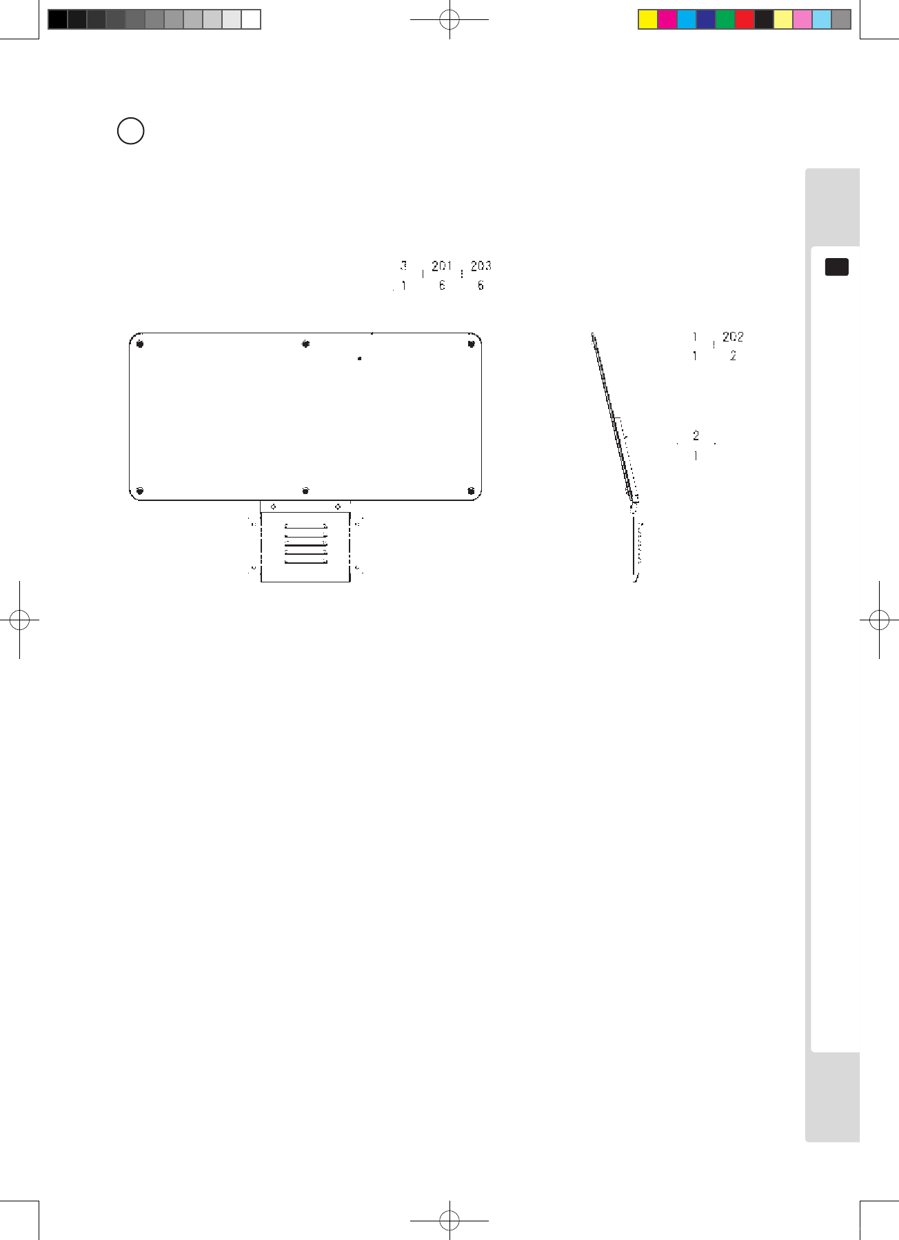
2 ASSY CABINET UR (LCB-1000UK) (D-1/3)
Lindburg.indb 54 2/16/2007 19:12:43
Parts list
55
15
2 ASSY CABINET UR (LCB-1000UK) (D-2/3)
Lindburg.indb 55 2/16/2007 19:12:43

56
Parts list
15
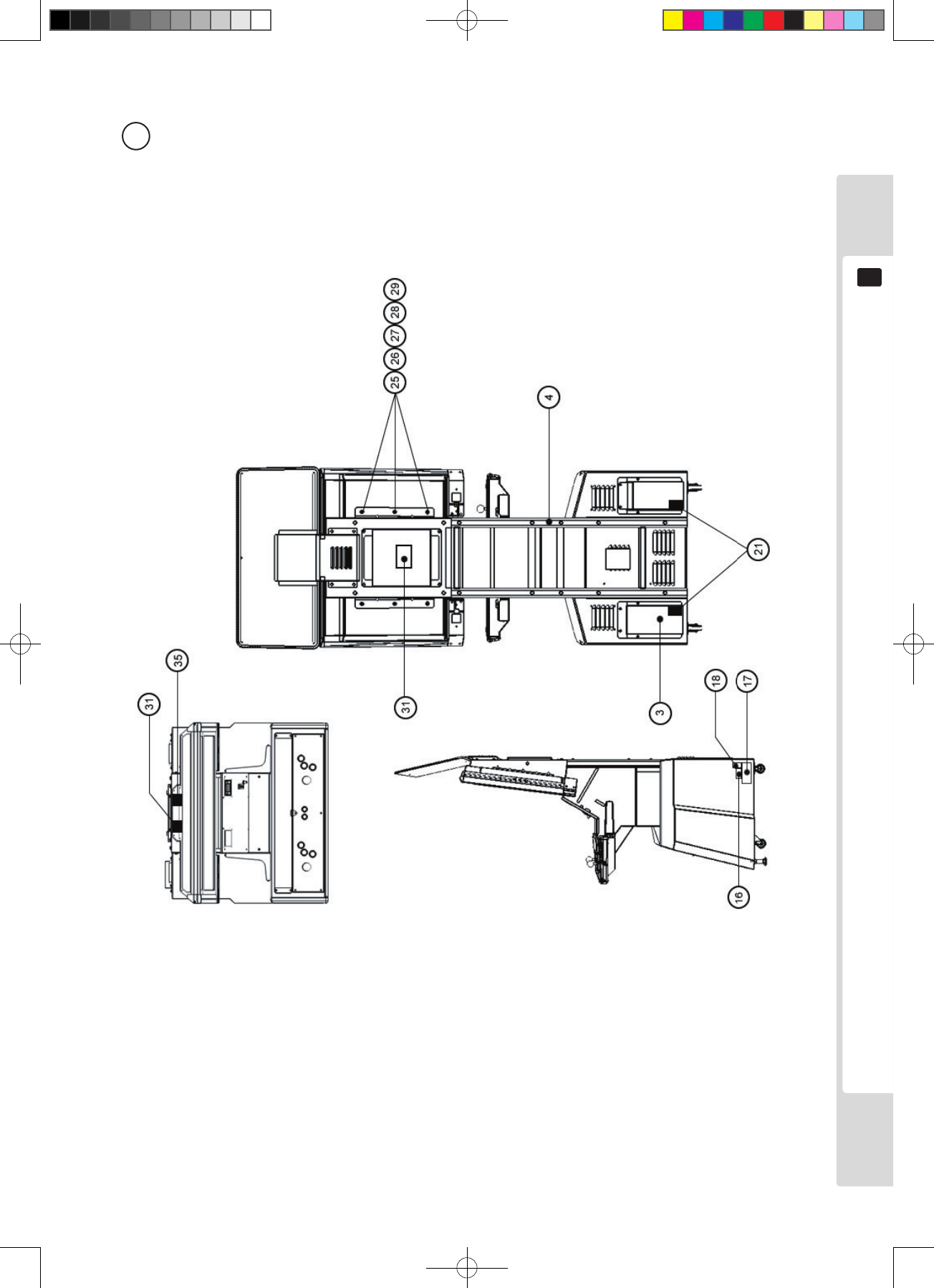
ITEM NO. PART NO. DESCRIPTION NOTE
1 LCB-1100UK ASSY BASE CABINET
2 LCB-1270UK ASSY SERVICE DOOR
3 LCB-1300UK ASSY AC UNIT
4 LCB-1500UK ASSY REAR FREAME
5 LCA-1600UK ASSY MONITOR 32"
6 LCA-1700UK ASSY BILLBOARD W/O DESIGN
7 LCB-2000UK ASSY CONTROL BOX
8 LCB-2100UK ASSY ENTRY BOX
9 LCB-2150UK ASSY ENTRY LID
10 LCB-2170UK ASSY COIN SELECTOR
11 LCA-2180UK ASSY SWITCH UNIT
12 LCA-2190UK ASSY I/O UNIT
13 LCA-4000UK ASSY PWR SUPPLY
14 LCA-4050UK ASSY SUB ELEC
16 421-7988-91UK STICKER SERIAL NUMBER
17 LB1046 LABEL TESTED FOR ELEC. SAFETY
18 LB1130 LABEL WEEE WHEELIE BIN
21 421-7020UK STICKER CAUTION FORK
24 421-9168-01 STICKER COIN METER
25 280-5113 COLLAR FOR NANAO MONITOR
26 280-5114 SPACER 6.4-25X2
27 253-5569 BUSH FOR LCD
28 253-5570 CAP FOR LCD
29 123-5123 STUD BOLT M6 FOR LCD
30 LCB-1050UK ASSY MID BOX
31 LB1102 STICKER DANGEROUS VOLTAGE
35 LB1104 STICKER CAUTION FORK
101 220-5643UK COIN METER SMALL
2 ASSY CABINET UR (LCB-1000UK) (D-3/3)
Lindburg.indb 56 2/16/2007 19:12:43
Parts list
57
15
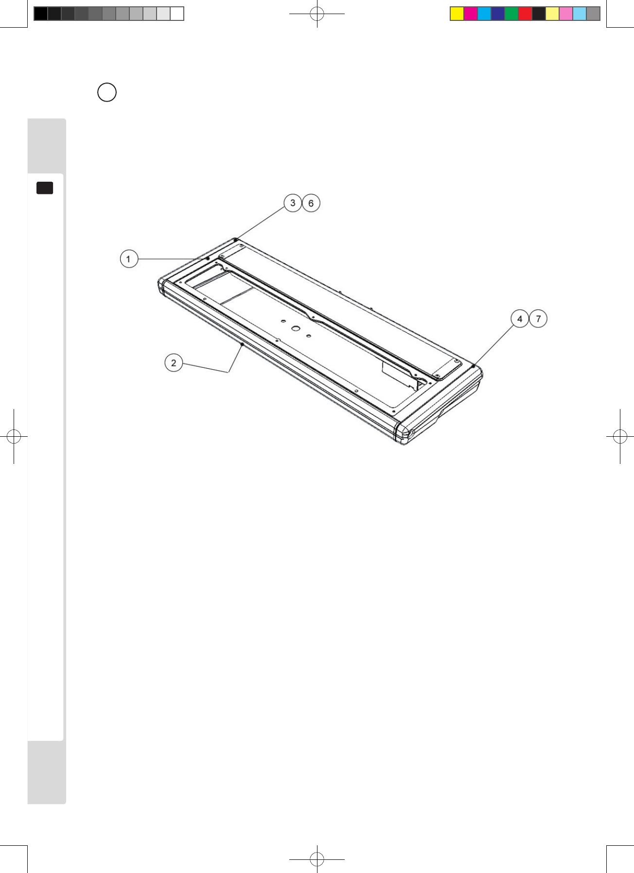
3 ASSY BASE CABINET (LCA-1100UK) (D-1/2)
Lindburg.indb 57 2/16/2007 19:12:44

58
Parts list
15
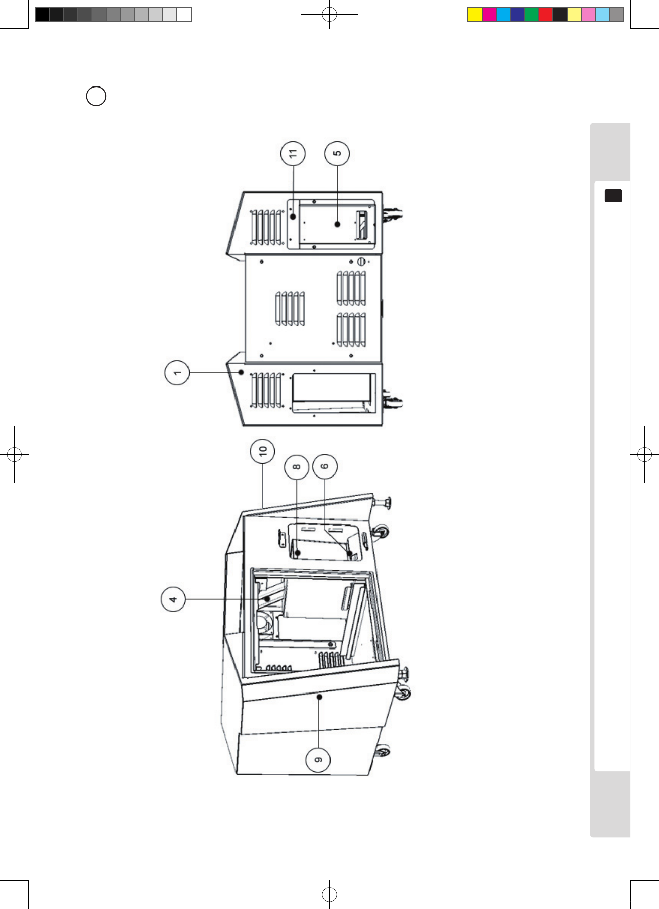
ITEM NO. PART NO. DESCRIPTION NOTE
1 LCB-1150UK ASSY BASE BOX
4 LCB-1101UK REJECT DUCT
5 LCB-1102UK COM BRKT
6 LCA-1103UK FLOOR LID
8 PP1087 BAX CASH FOR MINI DOOR
9 LCB-1152UK STICKER BASE UNIT L
10 LCB-1153UK STICKER BASE UNIT R
11 LCB-1109UK PLATE COM BRKT COVER
3 ASSY BASE CABINET (LCA-1100UK) (D-2/2)
Lindburg.indb 58 2/16/2007 19:12:44
Parts list
59
15
4 ASSY BASE BOX (LCA-1150UK)
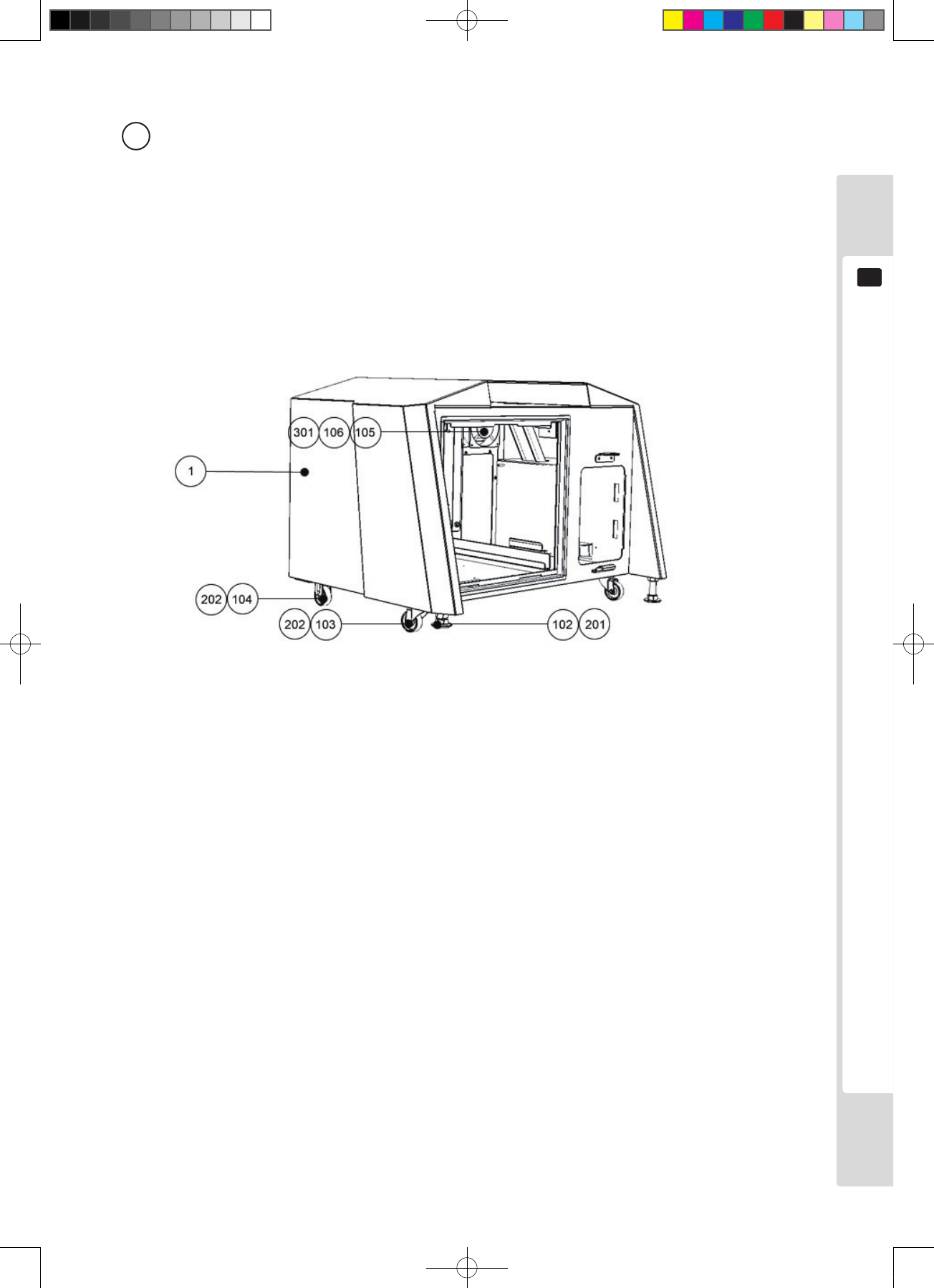
ITEM NO. PART NO. DESCRIPTION
1 LCB-1151UK BASE BOX LBG
102 601-5699X LEG ADJUSTER BOLT M16X75 SEGA
103 601-11635X-SUK CASTOR 50 SWIVEL (BLACK)
104 601-11635X-FUK CASTOR 50 FIXED (BLACK)
105 FN102 FAN GUARD
106 260-0011-02 AC FAN 100V
201 050-H01600 M16 NUT PAS
301 LGJ-60036UK WH BILLBOARD FAN AC
Lindburg.indb 59 2/16/2007 19:12:44
60
Parts list
15
5 ASSY SERVICE DOOR (LCB-1270UK)
ITEM NO. PART NO. DESCRIPTION
1 LCB-1271UK SERVICE DOOR
2 DP-1167UK TNG LKG
101 220-5575UK LOCK (J9117) W/KEY
Lindburg.indb 60 2/16/2007 19:12:45
Parts list
61
15
6 ASSY AC UNIT (LCB-1300UK)
ITEM NO. PART NO. DESCRIPTION
1 LCB-1301UK AC BRKT
3 LB1096 STKR PROTECT EARTH (NOT SHOWN)
101 EP1381 FILTER IEC & SW 6A ROXBURGH
301 LCA-60001UK WH AC BKT (NOT SHOWN)
302 600-9010-44K WH EARTH 100MM M4/M4 (NOT SHOWN)
6 ASSY AC UNIT (LCB-1300UK)
Lindburg.indb 61 2/16/2007 19:12:45
62
Parts list
15
7 ASSY REAR FRAME (LCB-1500UK)
ITEM NO. PART NO. DESCRIPTION
1 LCB-1501UK REAR FRAME
2 LCB-1502UK MONITOR SUPPORT LID
3 105-5549UK SW REG BRKT LCA
4 LCB-1511UK BRKT MONITOR SUPPORT
101 400-5461-01 SW REG FOR LCD 32TYPE
301 LCA-60017UK WH LCD POWER 24V
302 600-9010-44K WH EARTH 100MM M4/M4
303 600-9025-44K WH EARTH 250MM M4/M4
304 600-9090-44K WH EARTH 900MM M4/M4
Lindburg.indb 62 2/16/2007 19:12:45
Parts list
63
15
8 ASSY MONITOR 32" (LCA-1600UK) (D-1/2)
Lindburg.indb 63 2/16/2007 19:12:48

64
Parts list
15
8 ASSY MONITOR 32" (LCA-1600UK) (D-2/2)
ITEM NO. PART NO. DESCRIPTION
1 LCA-1650UK ASSY SPEAKER L
2 LCA-1660UK ASSY SPEAKER R
3 LCA-1602UK LCD SIDE FRAME LCX L
4 LCA-1603UK LCD SIDE FRAME LCX R
5 LCA-1604UK LIGHT BOX BRKT
6 LCA-1605UK AL HOLD BRKT
7 140-5090 END CAP L
8 140-5091 END CAP R
9 140-5092 HORIZONTAL FRAME 32V
10 LCA-1601UK LIGHT BOX
11 LCA-1606XUK LID LIGHT BOX
12 LCA-1607XUK FRONT LIGHT PLATE
13 LCA-1608X DISPLAY PLATE LCX
14 LCA-1609UK WINDOW PLATE BLBD FRONT LIGHT
15 LCA-1610XUK SPEAKER BRKT LCX A
16 LCA-1611UK SPEAKER BRKT LCX B
17 LCA-1612UK WINDOW PLATE BRKT
19 423-0355 EMBLEM SEGA
101 200-6046 ASSY LCD DSPL 32TYPE K
102 390-0100-18XUK ASSY FL TRAY LCB 100V 18W
103 390-0100-18DUK FL TUBE 18W T8 600MM
201 000-P00412-WB M SCR PH W/FS BLK M4×12
202 000-T00408-0C M SCR TH CRM M4×8
203 000-P00312-WB M SCR PH W/FS BLK M3×12
204 010-P00316-F S-TITE SCR PH W/F M3×16
205 012-P00308-0B TAP SCR #2 PH BLK 3×8
206 050-F00300 FLG NUT M3
207 000-P00306-W M SCR PH W/FS M3×6
301 LCA-60013UK WH SP MONITOR
Lindburg.indb 64 2/16/2007 19:12:48
Parts list
65
15
9 ASSY SPEAKER L (LCA-1560UK)
ITEM NO. PART NO. DESCRIPTION
1 140-5089 SPEAKER COVER FOR 130-5260
2 LCA-1651YUK SPEAKER HOOK L
101 130-5260 SPKR BOX 6OHM 15/40W W/SHLD
201 000-P00305 M SCR PH M3×5
202 012-P00406 TAP SCR #2 PH 4×6
Lindburg.indb 65 2/16/2007 19:12:49
66
Parts list
15
10 ASSY SPEAKER R (LCA-1660UK)
ITEM NO. PART NO. DESCRIPTION
1 140-5089 SPEAKER COVER FOR 130-5260
2 LCA-1661YUK SPEAKER HOOK R
101 130-5260 SPKR BOX 6OHM 15/40W W/SHLD
201 000-P00305 M SCR PH M3×5
202 012-P00406 TAP SCR #2 PH 4×6
Lindburg.indb 66 2/16/2007 19:12:49
Parts list
67
15
11 ASSY BILLBOARD W/O DESIGN (LCA-1700UK)
ITEM NO. PART NO. DESCRIPTION
1 LCA-1701UK BILLBOARD BASE
2 LCA-1702UK BILLBOARD HOLDER
3 LCA-1703UK BILLBOARD FRONT PLATE
201 FAS-290045 HEX SKT LH CAP SCR STN M4×6
202 000-T00408-0B M SCR TH BLK M4×8
203 280-6686-01 SP WSHR 4.5×16×4
Lindburg.indb 67 2/16/2007 19:12:50
68
Parts list
15
12 ASSY CONTROL BOX (LCB-2000UK)
ITEM NO. PART NO. DESCRIPTION
1 LCA-2030UK ASSY CONTROL BOX UPPER
2 LCA-2060UK ASSY CONTROL BOX LOWER
3 LCA-2001UK HINGE PLATE L
4 LCA-2002UK HINGE PLATE R
6 LCA-2004UK SIDE COVER L
7 LCA-2005UK SIDE COVER R
201 000-P00408-W M SCR PH W/FS M4×8
202 012-P00412 TAP SCR #2 PH 4×12
Lindburg.indb 68 2/16/2007 19:12:51
Parts list
69
15
13 ASSY CONTROL BOX UPPER (LCA-2030UK) (D-1/2)
Lindburg.indb 69 2/16/2007 19:12:52

70
Parts list
15
13 ASSY CONTROL BOX UPPER (LCA-2030UK) (D-2/2)
ITEM NO. PART NO. DESCRIPTION
1 LCA-2031UK CONTROL BOX UPPER
2 LCA-2032X CONTROL PANEL
3 LCA-2033UK FRONT LINE
4 LCA-2034UK NUT PLATE
5 LCA-2035 END COVER
6 LCA-2036UK CCFL HOLDER ( OPTION)
7 LCA-2037UK CCFL CAP (OPTION)
8 LCA-2038UK DIFFUSION PLATE
9 LCA-2039XUK INSTRUCTION COVER
10 LCA-2040UK INVERTER COVER (OPTION)
12 SHE-1238 SPACER COLLAR
14 LCA-2042UK TONGUE RETAINER
101 390-6815-WH-V CCFL D=15 L=700 WHITE W/V.TUBE (OPTION)
102 838-14587 CCFL INV (OPTION)
103 280-5275-SR10 CORD CLAMP SR10 (OPTION)
201 000-P00410-W M SCR PH W/FS M4×10
202 000-F00306 M SCR FH M3×6
203 000-P00408-W M SCR PH W/FS M4×8
204 010-F00312 S-TITE SCR FH M3×12
205 000-P00308-W M SCR PH W/FS M3×8
206 012-P00308 TAP SCR #2 PH 3×8
207 000-P02610 M SCR PH M2.6×10
208 FAS-680011 FLT WSHR POLY 2.7-6×0.5
301 LCA-60022UK WH COLD CATHODE CONTROL (OPTION)
Lindburg.indb 70 2/16/2007 19:12:52
Parts list
71
15
14 ASSY CONTROL BOX LOWER (LCA-2060UK)
ITEM NO. PART NO. DESCRIPTION
1 LCA-2061UK CONTROL BOX LOWER
2 LCA-2062YUK SLIDE TONGUE L
3 LCA-2063YUK SLIDE TONGUE R
4 LCA-2064UK TONGUE SPACER
5 LCA-2065 TONGUE SPRING
6 LCA-2066UK TONGUE GUIDE
7 LCA-2067 TONGUE ROLLER
201 000-P00416-W M SCR PH W/FS M4×16
202 000-P00408-W M SCR PH W/FS M4×8
203 050-F00400 FLG NUT M4
Lindburg.indb 71 2/16/2007 19:12:52
72
Parts list
15
15 ASSY ENTRY BOX (LCB-2100UK)
ITEM NO. PART NO. DESCRIPTION
1 LCA-2101XUK ENTRY BOX
2 LCA-2102UK TONGUE
3 LCA-2103UK CONN PANEL PLATE
4 LCA-2104UK STICKER ENTRY UNIT L
5 LCA-2105UK STICKER ENTRY UNIT R
101 220-5575UK LOCK (J9117) W/KEY
102 601-11440 STAY
201 000-P00408-W M SCR PH W/FS M4×8
202 050-F00400 FLG NUT M4
Lindburg.indb 72 2/16/2007 19:12:53
Parts list
73
15
16 ASSY ENTRY LID (LCB-2150UK)
ITEM NO. PART NO. DESCRIPTION
1 LCA-2151UK ENTRY LID
2 LCA-2152UK LID FRONT PANEL
3 LCA-2153 FLAT LID (USED WHEN NO CARD RW FITTED)
4 LCA-2154 OPEN LID
6 LCA-2158UK PLATE LID HOOK
7 250-5669 ASSY REJECT BUTTON L59
8 220-5428-09 COIN ENTRY
10 LCB-2157UK STICKER ENTRY UNIT FRONT
201 000-P00408-W M SCR PH W/FS M4×8
202 000-P00310-W M SCR PH W/FS M3×10
203 000-P00306-W M SCR PH W/FS M3×6
Lindburg.indb 73 2/16/2007 19:12:53
74
Parts list
15
17 ASSY COIN SELECTOR (LCB-2170UK)
ITEM NO. PART NO. DESCRIPTION
1 LCA-2171UK COIN SELECTOR BASE
2 LCA-2172UK UPPER COIN CHUTE
3 CFB-1683 REJECT SHAFT
4 LCA-2174UK LOWER COIN CHUTE
5 VSC-1474UK REJECT CAM
103 EP1380-R CREDIT BD EXCEL
104 280-L01640-PS STANDOFF 16MM 4MM PANEL SMALL
201 000-P00408-W M SCR PH W/FS M4×8
202 000-P00308-W M SCR PH W/FS M3×8
203 050-H00500 HEX NUT M5
204 060-S00500 SPR WSHR M5
205 060-F00500 FLT WSHR M5
206 065-E00300 E RING 3MM
301 LCA-60021UK WH EXCEL CREDIT BOARD
Lindburg.indb 74 2/16/2007 19:12:54
Parts list
75
15
18 ASSY SWITCH UNIT (LCA-2180UK)
ITEM NO. PART NO. DESCRIPTION
1 LCA-2181UK SW BRKT
2 LCA-2182XUK LATCH
3 LCA-2183UK LATCH HOLDER
4 CTF-1173 LATCH SPRING L
5 CTF-1174 LATCH SPRING R
6 421-12136UK STICKER SW PANEL LCA
101 838-14548-01UK SW & C VOL BD
201 065-E00700 E RING 7MM
202 000-P00408-W M SCR PH W/FS M4×8
203 000-P00308-W M SCR PH W/FS M3×8
18 ASSY SWITCH UNIT (LCA-2180UK)
Lindburg.indb 75 2/16/2007 19:12:55
76
Parts list
15
19 ASSY I/O UNIT (LCA-2190UK)
ITEM NO. PART NO. DESCRIPTION
1 LCA-2191 IO BD BASE
2 837-14572 I/O CONTROL BD 3 FOR JVS COM
201 000-P00320-W M SCR PH W/FS M3×20
19 ASSY I/O UNIT (LCA-2190UK) 19 ASSY I/O UNIT (LCA-2190UK)
Lindburg.indb 76 2/16/2007 19:12:55
Parts list
77
15
20 ASSY POWER SUPPLY (LCA-4000UK)
ITEM NO. PART NO. DESCRIPTION
1 SHT-4904 ELEC BRKT
101 400-5457-01 SW REGU ATX/JVS AUTO
201 000-P00308-W M SCR PH W/FS M3×8
Lindburg.indb 77 2/16/2007 19:12:55
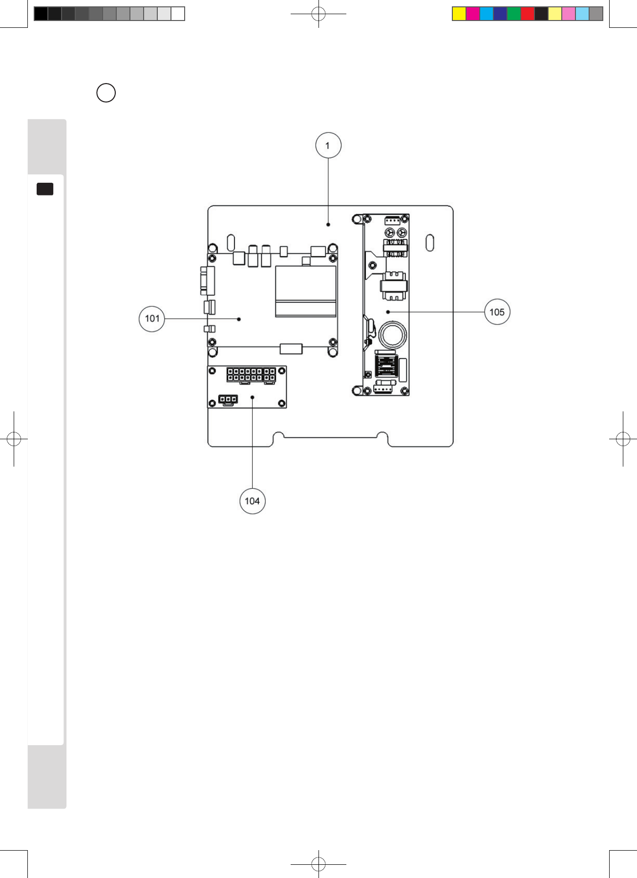
78
Parts list
15
21 ASSY SUB ELEC (LCA-4050UK)
ITEM NO. PART NO. DESCRIPTION
1 LCA-4051UK WOODEN BASE SUB ELEC
101 838-14515-A0191 SOUND AMP ANALOG IN
104 838-14551 DISTRIBUTION BD
105 400-050-024-01 PSU 24VDC 50W MW LPS 50-24
201 000-P00308-W M SCR PH W/FS M3×8
202 011-T03516 TAP SCR TH 3.5×16
203 011-P00320 TAP SCR PH 3×20
301 LCA-60007UK WH AC SUB ELEC SW REGU FOR AMP
303 LCA-60010UK WH DC SUB ELEC SW REGU FOR AMP
304 LCA-60012UK WH SPEAKERS
305 LCA-60026UK WH AC DIST
306 600-7158-0200 CA AUDIO RCA TO RCA 2CH 200CM
Lindburg.indb 78 2/16/2007 19:12:56
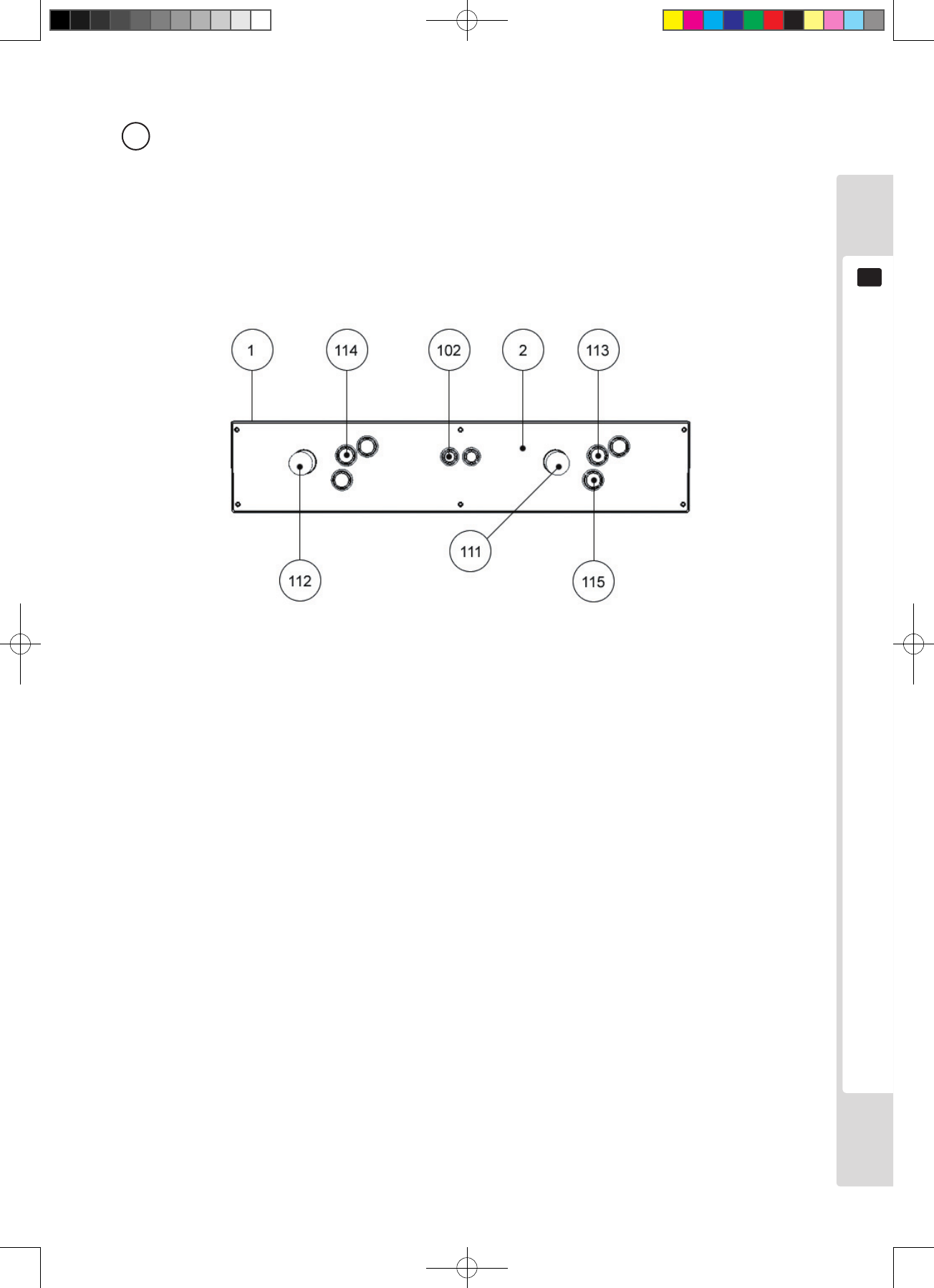
Parts list
79
15
23 ASSY CONTROL PANEL 2L6B (LCB-2500UK)
ITEM NO. PART NO. DESCRIPTION
1 LCA-2501UK CTRL PNL BASE 2L6B
2 LCA-2502UK CTRL PNL PLATE 2L6B
102 509-5765-01 SW PB D24 YELLOW
111 610-0404-01 ASSY 8 WAY JOYSTICK GREEN
112 610-0404-02 ASSY 8 WAY JOYSTICK PINK
113 509-5755-01 SW PB D30 GREEN
114 509-5755-02 SW PB D30 PINK
115 253-5185UK CAP SW 30PH
201 000-P00412-W M SCR PH W/FS M4×12
301 LCA-60023UK WH CONTROL PANEL 1
302 LCA-60024UK WH CONTROL PANEL 2P
23 ASSY CONTROL PANEL 2L6B (LCB-2500UK)
Lindburg.indb 79 2/16/2007 19:12:56
80
Wire color reference table
16
Note 1 If the units digit of the code is non-zero, the tens digit indicates the background color and the
units digit indicates the spiral color.
E.g. 51... White/Red
Note 2 The letter after the wire color code indicates the thickness of the wire.
U: AWG16
K: AWG18
L : AWG20
None: AWG22
The wire color codes used in the overall wiring diagrams in the next chapter are as stated below.
CODE WIRE COLOR
10 RED
20 BLUE
30 YELLOW
40 GREEN
50 WHITE
70 ORANGE
80 BLACK
90 GRAY
A PINK
B SKYBLUE
C BROWN
D PURPLE
E LIGHT GREEN
RED WHITE
Wire color reference table
16
Lindburg.indb 80 2/16/2007 19:12:57
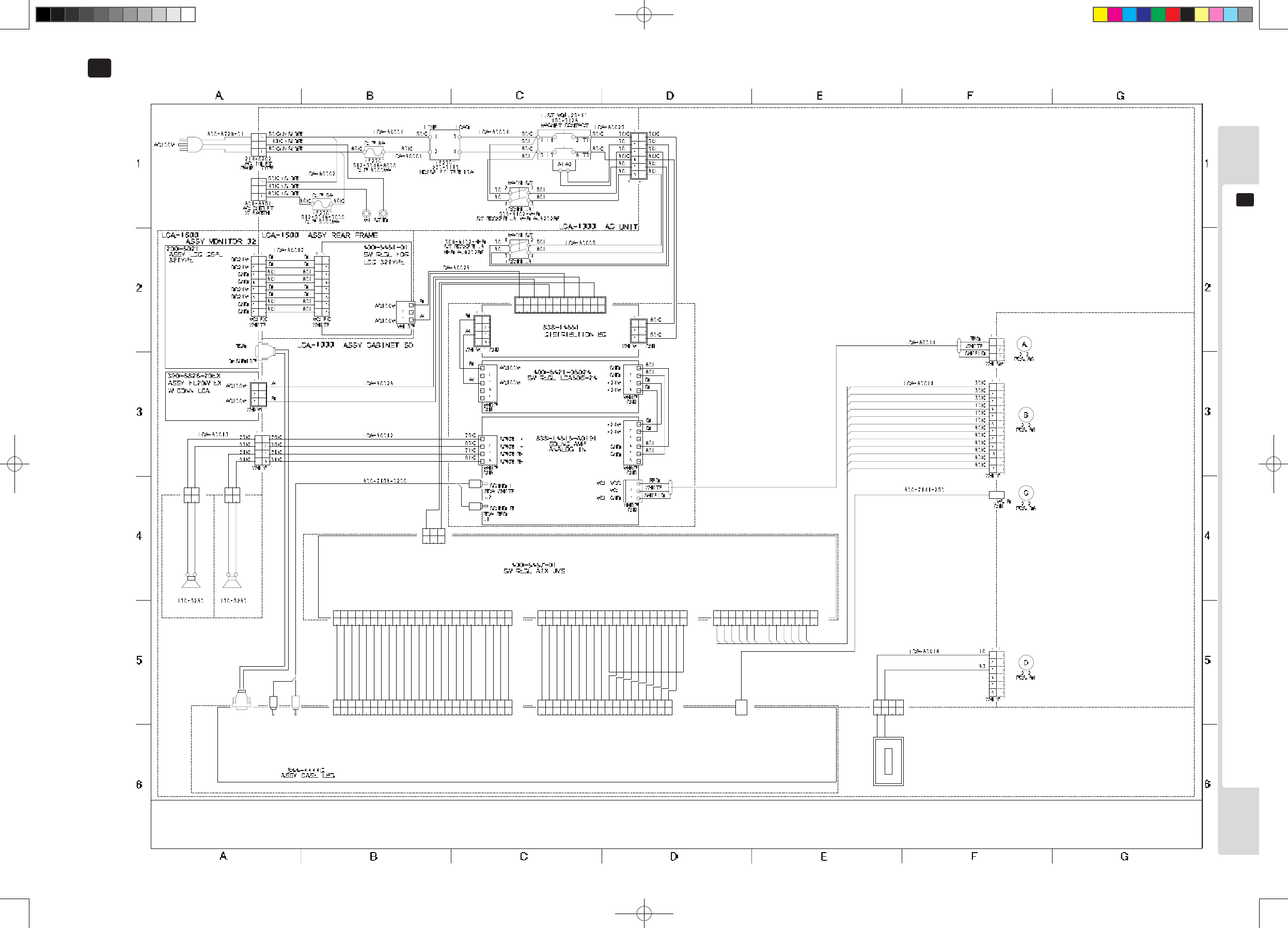
81
Overall wiring diagrams
18
Overall wiring diagrams (D-1/2)
17
䎯䎦䎤䎐 䎓 䎓 䎓 䎔
䎺䎲䎲䎧䎨䎱 䎥䎤䎶䎨 䎰䎤 䎬 䎱
䎹 䎬 䎧䎨䎲 䎲䎸䎷䎔
䎵䎦䎤 䎺䎫 䎬 䎷䎨
䎶䎲䎸䎱䎧 䎯
䎵䎪䎥
䎶䎲䎸䎱䎧 䎵
䎧䎐䎶䎸䎥䎔䎘䎳
䎵䎦䎤 䎵䎨䎧
䎳
䎔
䎕
䎖
䎗
䎘
䎙
䎚
䎛
䎜
䎔 䎓
䎔 䎔
䎔 䎕
䎦
䎔 䎛
䎔 䎚
䎔 䎙
䎔 䎘
䎔 䎗
䎔 䎖
䎔 䎜
䎕 䎓
䎕 䎔
䎕 䎕
䎕 䎖
䎕 䎗
䎪䎱䎧 䎥䎯䎤䎦䎮 䎋䎸䎯䎔 䎓䎓 䎚 䎤䎺䎪䎔䎙 䎌
䎎䎘䎹
䎪䎱䎧
䎎䎖 䎑 䎖䎹
䎎䎖 䎑 䎖䎹 䎥䎵䎲䎺䎱 䎋 䎸䎯䎔 䎓䎓 䎚 䎤䎺䎪䎔 䎙 䎌
䎥䎵䎲䎺䎱 䎋䎸䎯 䎔䎓 䎓䎚 䎤䎺䎪䎔 䎙 䎌
䎥䎯䎤䎦䎮 䎋䎸䎯䎔 䎓䎓䎚 䎤䎺䎪䎔䎙 䎌
䎼䎨䎯䎯䎲䎺䎋 䎸䎯䎔 䎓䎓 䎚 䎤䎺䎪䎔 䎙 䎌
䎥䎯䎤䎦䎮 䎋䎸䎯䎔 䎓䎓䎚 䎤䎺䎪䎔䎙 䎌
䎥䎵䎲䎺䎱 䎋䎸䎯 䎔䎓 䎓䎚 䎤䎺䎪䎔 䎙 䎌
䎥䎵䎲䎺䎱 䎋䎸䎯 䎔䎓 䎓䎚 䎤䎺䎪䎔 䎙 䎌
䎼䎨䎯䎯䎲䎺䎋 䎸䎯䎔 䎓䎓 䎚 䎤䎺䎪䎔 䎙 䎌
䎎䎘䎶䎥
䎳䎺䎵 䏂 䎲䎮
䎥䎯䎤䎦䎮 䎋䎸䎯䎔 䎓䎓䎚 䎤䎺䎪䎔䎙 䎌
䎎䎖 䎑 䎖䎹
䎎䎖 䎑 䎖䎹
䎐䎔 䎕䎹
䎪䎱䎧
䎎䎔 䎕䎹
䎎䎔 䎕䎹
䎎䎘䎹
䎥䎯䎤䎦䎮 䎋䎸䎯䎔 䎓䎓䎚 䎤䎺䎪䎔䎙 䎌
䎥䎯䎤䎦䎮 䎋䎸䎯䎔 䎓䎓䎚 䎤䎺䎪䎔䎙 䎌
䎥䎯䎤䎦䎮 䎋䎸䎯䎔 䎓䎓䎚 䎤䎺䎪䎔䎙 䎌
䎥䎯䎤䎦䎮 䎋䎸䎯䎔 䎓䎓䎚 䎤䎺䎪䎔䎙 䎌
䎳䎶 䏂䎲䎱䎆
䎪䎱䎧
䎪䎱䎧
䎪䎱䎧
䎎䎘䎹
䎎䎘䎹
䎎䎘䎹
䎪䎱䎧
䎰䎲䎯䎨䎻
䎺䎫 䎬 䎷䎨
䎼䎨䎯䎯䎲䎺䎋 䎸䎯䎔 䎓䎓 䎚 䎤䎺䎪䎔 䎙 䎌
䎼䎨䎯䎯䎲䎺䎋 䎸䎯䎔 䎓䎓 䎚 䎤䎺䎪䎔 䎙 䎌
䎼䎨䎯䎯䎲䎺䎋 䎸䎯䎔 䎓䎓 䎚 䎤䎺䎪䎔 䎙 䎌
䎼䎨䎯䎯䎲䎺䎋 䎸䎯䎔 䎓䎓 䎚 䎤䎺䎪䎔 䎙 䎌
䎎䎔 䎕䎹
䎎䎔 䎕䎹
䎎䎘䎹
䎎䎘䎹
䎎䎔 䎕䎹
䎪䎱䎧
䎳
䎔
䎕
䎖
䎗
䎘
䎙
䎚
䎛
䎜
䎔 䎓
䎔 䎔
䎔 䎕
䎦
䎔 䎛
䎔 䎚
䎔 䎙
䎔 䎘
䎔 䎗
䎔 䎖
䎼䎨䎯䎯䎲䎺䎋 䎸䎯䎔 䎓䎓 䎚 䎤䎺䎪䎔 䎙 䎌
䎎䎖 䎑 䎖䎹䎵䎶
䎪䎱䎧
䎎䎘䎹
䎎䎔 䎕䎹
䎎䎔 䎕䎹
䎪䎱䎧
䎪䎱䎧
䎪䎱䎧
䎪䎱䎧
䎥䎮
䎥䎮
䎥䎮
䎥䎮
䎥䎮
䎥䎮
䎲䎵䎤䎱䎪䎨 䎋 䎸䎯䎔 䎓䎓䎚 䎤䎺䎪䎔䎙 䎌
䎪䎱䎧
䎪䎱䎧
䎰䎲䎯䎨䎻
䎥䎮
䎥䎮
䎺䎫 䎬 䎷䎨
䎪䎱䎧
䎥䎵
䎭䎹䎶 䎤 䎭䎹䎶 䎬 䎒䎲
䎭䎹䎶
䎬 䎒䎲
䎕䎕䎓䎐䎘䎚䎜䎛䎐䎓䎔
䎜䎜䎜䎜䎜䎓
䎦䎲 䎬 䎱 䎰䎨䎷䎨䎵 䎔
䎰䎤䎪 䎦䎱䎷䎵 䎗䎳
䎰䎽䎙䎚 䎗䎐䎧䎦䎘䎹䎐䎧䎗䎔 䎭䎦
䎛䎖
䎔䎓
䎺䎫 䎋 䎼䎯 䎌
䎵䎨䎧
䎥䎯䎤䎦䎮
䎳
䎔
䎕
䎖
䎗
䎦
䎯䎦䎤䎐 䎔 䎙 䎘 䎓 䎤䎶䎶䎼 䎶䎳䎨䎤䎮䎨䎵 䎯
䎵䎨䎧 䎋 䎸䎯䎔 䎓 䎓 䎚 䎤䎺䎪䎔 䎙 䎌
䎵䎨䎧 䎋 䎸䎯䎔 䎓 䎓 䎚 䎤䎺䎪䎔 䎙 䎌
䎯䎦䎤䎐䎙䎓䎓䎕䎛
䎯䎦䎤䎐 䎔 䎙 䎙 䎓 䎤䎶䎶䎼 䎶䎳䎨䎤䎮䎨䎵 䎵
䎳
䎔
䎕
䎖
䎗
䎘
䎙
䎚
䎛
䎜
䎔 䎓
䎔 䎔
䎔 䎕
䎦
䎔 䎛
䎔 䎚
䎔 䎙
䎔 䎘
䎔 䎗
䎔 䎖
䎔 䎜
䎕 䎓
䎕 䎔
䎕 䎕
䎕 䎖
䎕 䎗
䎯䎦䎤䎐 䎗 䎓 䎓 䎓
䎎䎖 䎑 䎖䎹
䎪䎱䎧
䎎䎘䎹
䎪䎱䎧
䎎䎖 䎑 䎖䎹
䎥䎯䎤䎦䎮
䎵䎨䎧
䎵䎨䎧
䎥䎯䎤䎦䎮
䎯
䎵
䎎
䎐
䎎
䎐
䎤䎶䎶䎼 䎳䎺䎵 䎶䎳䎯䎼
䎺䎫 䎋 䎼䎯 䎌
䎳
䎔
䎕
䎦
䎳
䎔
䎕
䎦
䎺䎫 䎋 䎼䎯 䎌
䎙䎓䎓䎐䎚䎓䎓䎜䎐䎕䎓䎓䎓
䎚䎘䎮
䎜䎘䎮
䎚䎔䎮
䎜䎔䎮
䎳 䎬 䎱䎮 䎋䎸䎯 䎔䎓䎓 䎚 䎤䎺䎪䎔 䎛 䎌
䎥䎯䎸䎨 䎋䎸䎯 䎔䎓 䎓䎚 䎤䎺䎪䎔䎛 䎌
䎜䎘
䎗䎘
䎵䎨䎧 䎋 䎸䎯䎔 䎓䎓 䎚 䎤䎺䎪䎔 䎙 䎌
䎵䎨䎧 䎋 䎸䎯䎔 䎓䎓 䎚 䎤䎺䎪䎔 䎙 䎌
䎵䎨䎧 䎋 䎸䎯䎔 䎓䎓 䎚 䎤䎺䎪䎔 䎙 䎌
䎯䎦䎤䎐䎙䎓䎓䎕䎛
䎵䎨䎧 䎋 䎸䎯䎔 䎓䎓 䎚 䎤䎺䎪䎔 䎙 䎌
䎵䎨䎧 䎋 䎸䎯䎔 䎓䎓 䎚 䎤䎺䎪䎔 䎙 䎌
䎐䎔 䎕䎹
䎎䎖 䎑 䎖䎹
䎎䎖 䎑 䎖䎹
䎎䎘䎶䎥
䎎䎔 䎕䎹
䎎䎔 䎕䎹
䎎䎘䎹
䎳䎺䎵 䏂 䎲䎮
䎪䎱䎧
䎪䎱䎧
䎳䎶 䏂䎲䎱䎆
䎪䎱䎧
䎪䎱䎧
䎪䎱䎧
䎎䎘䎹
䎎䎘䎹
䎎䎘䎹
䎺䎫 䎬 䎷䎨䎒䎦䎱䎔
䎰䎲䎯䎨䎻
䎪䎱䎧
䎎䎔 䎕䎹
䎎䎔 䎕䎹
䎎䎘䎹
䎎䎘䎹
䎎䎔 䎕䎹
䎳
䎔
䎕
䎖
䎗
䎘
䎙
䎚
䎛
䎜
䎔 䎓
䎔 䎔
䎔 䎕
䎦
䎔 䎛
䎔 䎚
䎔 䎙
䎔 䎘
䎔 䎗
䎔 䎖
䎔 䎜
䎕 䎓
䎤䎦䎔䎓 䎓䎹
䎤䎦䎔䎓 䎓䎹
䎥䎮 䎋䎸䎯䎔䎓䎓䎚 䎆䎔䎙 䎌
䎵䎨䎧 䎋 䎸䎯䎔 䎓䎓 䎚 䎤䎺䎪䎔 䎙 䎌
䎥䎮 䎋䎸䎯䎔䎓䎓䎚 䎆䎔䎙 䎌
䎥䎮 䎋䎸䎯䎔䎓䎓䎚 䎆䎔䎙 䎌
䎥䎮 䎋䎸䎯䎔䎓䎓䎚 䎆䎔䎙 䎌
䎥䎮 䎋䎸䎯䎔䎓䎓䎚 䎆䎔䎙 䎌
䎳 䎬 䎋䎸䎯䎔䎓䎓䎚 䎆䎔䎙 䎌
䎥䎮 䎋䎸䎯䎔䎓䎓䎚 䎆䎔䎙 䎌
䎥䎮 䎋䎸䎯䎔䎓䎓䎚 䎆䎔䎙 䎌
䎥䎮 䎋䎸䎯䎔䎓䎓䎚 䎆䎔䎙 䎌
䎳 䎬 䎋䎸䎯䎔䎓䎓䎚 䎆䎔䎙 䎌
䎥䎵䎋䎸䎯䎔䎓䎓䎚 䎆䎔䎙 䎌
䎎䎘䎶䎥
䎎䎔 䎕䎹
䎎䎘䎹
䎎䎔 䎕䎹
䎎䎖 䎑 䎖䎹䎵䎶
䎪䎱䎧
䎪䎱䎧
䎪䎱䎧
䎪䎱䎧
䎰䎲䎯䎨䎻
䎺䎫 䎬 䎷䎨䎒䎦䎱䎖
䎎䎖 䎑 䎖䎹
䎵䎼䎕䎎
䎪䎱䎧
䎪䎱䎧
䎪䎱䎧
䎪䎱䎧
䎳
䎔
䎕
䎖
䎗
䎘
䎙
䎚
䎛
䎜
䎔 䎓
䎔 䎔
䎔 䎕
䎦
䎔 䎗
䎔 䎖
䎪䎱䎧
䎪䎱䎧
䎪䎱䎧
䎪䎱䎧
䎪䎱䎧
䎪䎱䎧
䎪䎱䎧
䎎䎔䎕䎹
䎎䎔䎕䎹
䎛䎓䎮
䎛䎓䎮
䎛䎓䎮
䎖䎓䎮
䎖䎓䎮
䎖䎓䎮
䎛䎓䎮
䎛䎓䎮
䎛䎓䎮
䎎䎖 䎑 䎖䎹
䎎䎘䎹
䎎䎘䎹
䎎䎘䎹
䎎䎔䎕䎹
䎰䎲䎯䎨䎻
䎺䎫 䎬 䎷䎨
䎔䎓䎮
䎔䎓䎮
䎔䎓䎮
䎥䎯
䎤䎯
䎳
䎔
䎕
䎖
䎦
䎺䎫 䎋 䎼䎯 䎌
䎯䎦䎤䎐 䎗 䎓 䎘 䎓 䎤䎶䎶䎼 䎶䎸䎥 䎨䎯 䎨䎦
䎯䎦䎤䎐䎙 䎓䎓 䎔䎓
䎯䎦䎤䎐䎙 䎓䎓 䎓䎚
䎳
䎔
䎕
䎖
䎗
䎘
䎙
䎚
䎛
䎜
䎔 䎓
䎔 䎔
䎔 䎕
䎦
䎥䎯
䎤䎯
䎥䎯
䎥䎯
䎤䎯
䎺䎫 䎋 䎹䎯 䎌 䎒䎦䎱䎖
䎤䎯
䎗䎖䎮
䎘䎓䎮
䎛䎓䎮
䎬 䎧䎘
䎬 䎧䎘
䎗䎖䎮
䎯䎦䎤䎐䎙䎓䎓 䎕䎘
䎛䎓䎯
䎘䎓䎯
䎯䎦䎤䎐䎙 䎓䎓 䎓䎘
Lindburg.indb 81 2/16/2007 19:13:05
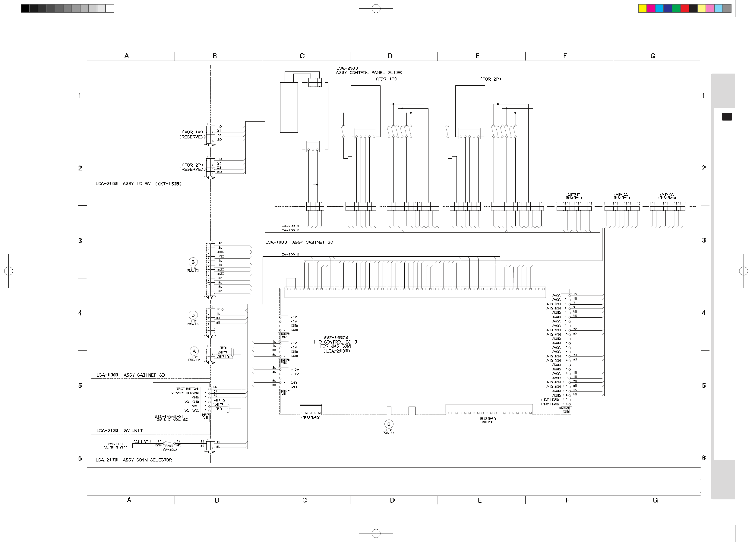
82
Overall wiring diagrams
18
(D-2/2)
䎱䎫䎘䎳
䎦䎱䎕
䎔
䎕
䎖
䎗
䎘
䎭䎹䎶 䎤
䎔
䎕
䎖
䎗
䎘
䎙
䎚
䎛
䎜
䎔 䎓
䎔 䎔
䎔 䎕
䎔 䎖
䎔 䎗
䎔 䎘
䎔 䎙
䎔 䎚
䎔 䎛
䎔 䎜
䎕 䎓
䎭䎹䎶 䎬 䎒䎲
䎭䎹䎶 䎥
䎦䎱䎗
䎦䎱䎘
䎭䎹䎶 䎬 䎒䎲
䎵䎤䎕䎓䎳
䎦䎱䎜
䎎䎔䎕䎹
䎎䎔䎕䎹
䎪䎱䎧
䎪䎱䎧
䎋 䎵䎨䎶䎨䎵䎹䎨䎧 䎌
䎔䎳 䎶䎺䎗 䎋 䎦䎤䎵䎧 䎶䎨䎱䎶䎨 䎌
䎕䎳 䎶䎺䎘 䎋 䎦䎤䎵䎧 䎥䎸䎶䎼 䎌
䎔䎳 䎶䎺䎘 䎋 䎦䎤䎵䎧 䎥䎸䎶䎼 䎌
䎎䎘䎹
䎎䎘䎹
䎕䎳 䎶䎺䎗 䎋 䎦䎤䎵䎧 䎶䎨䎱䎶䎨 䎌
䎪䎱䎧
䎲䎸䎷䎳䎸䎷 䎚
䎲䎸䎷䎳䎸䎷 䎛
䎪䎱䎧
䎲䎸䎷䎳䎸䎷 䎔䎖
䎲䎸䎷䎳䎸䎷 䎔䎕
䎲䎸䎷䎳䎸䎷 䎔䎓
䎲䎸䎷䎳䎸䎷 䎔䎔
䎲䎸䎷䎳䎸䎷 䎜
䎎䎔 䎕䎹
䎲䎸䎷䎳䎸䎷 䎔䎗
䎲䎸䎷䎳䎸䎷 䎕䎓
䎲䎸䎷䎳䎸䎷 䎔䎜
䎲䎸䎷䎳䎸䎷 䎔䎛
䎲䎸䎷䎳䎸䎷 䎔䎙
䎲䎸䎷䎳䎸䎷 䎔䎚
䎲䎸䎷䎳䎸䎷 䎔䎘
䎎䎔 䎕䎹
䎲䎸䎷 䎗 䎋䎦䎤䎵䎧䎕 䎶䎲䎯 䎑 䎌
䎲䎸䎷 䎕 䎋䎦䎤䎵䎧䎔 䎶䎲䎯 䎑 䎌
䎎䎨䎻䎹
䎎䎨䎻䎹
䎎䎘䎹
䎕 䎗
䎕 䎖
䎕 䎕
䎕 䎔
䎔
䎕
䎖
䎗
䎘
䎙
䎚
䎛
䎜
䎔 䎓
䎔 䎔
䎔 䎕
䎔 䎖
䎔 䎗
䎔 䎘
䎔 䎙
䎔 䎚
䎔 䎛
䎔 䎜
䎕 䎓
䎙 䎓
䎘 䎜
䎘 䎛
䎘 䎚
䎘 䎙
䎘 䎘
䎘 䎗
䎘 䎖
䎘 䎕
䎘 䎔
䎘 䎓
䎗 䎜
䎗 䎛
䎗 䎚
䎗 䎙
䎗 䎘
䎗 䎗
䎗 䎖
䎗 䎕
䎗 䎔
䎗 䎓
䎖 䎜
䎖 䎛
䎖 䎚
䎖 䎙
䎖 䎘
䎖 䎗
䎖 䎖
䎖 䎕
䎖 䎔
䎖 䎓
䎕 䎜
䎕 䎛
䎕 䎚
䎕 䎙
䎕 䎘
䎎䎘䎹
䎎䎘䎹
䎎䎘䎹
䎎䎘䎹
䎪䎱䎧
䎪䎱䎧
䎪䎱䎧
䎎䎘䎹
䎪䎱䎧
䎔䎓
䎔䎓
䎔䎓
䎔䎓
䎔䎓
䎔䎓
䎛䎓
䎛䎓
䎛䎓
䎛䎓
䎪䎱䎧
䎪䎱䎧
䎪䎱䎧
䎪䎱䎧
䎕䎳 䎶䎷䎤䎵䎷
䎔䎳 䎶䎷䎤䎵䎷
䎕䎳 䎵 䎬 䎪䎫䎷
䎔䎳 䎵 䎬 䎪䎫䎷
䎔䎳 䎯䎨䎩䎷
䎕䎳 䎯䎨䎩䎷
䎕䎳 䎸䎳
䎔䎳 䎸䎳
䎕䎳 䎧䎲䎺䎱
䎔䎳 䎧䎲䎺䎱
䎔䎳 䎶䎺䎔
䎕䎳 䎶䎺䎔
䎕䎳 䎶䎺䎕
䎔䎳 䎶䎺䎕
䎕䎳 䎶䎺䎙
䎔䎳 䎶䎺䎙
䎔䎳 䎶䎺䎚
䎕䎳 䎶䎺䎖
䎔䎳 䎶䎺䎖
䎛䎓
䎛䎓
䎥
䎥䎘
䎤䎘
䎤
䎦
䎛䎓
䎛䎓
䎗䎘
䎗䎓
䎦䎘
䎨
䎨䎘
䎧䎘
䎕䎘
䎧
䎕䎓
䎚䎘
䎘䎚
䎘䎔
䎘䎖
䎘䎜
䎘䎛
䎘䎕
䎘䎗
䎚䎓
䎕䎳 䎶䎺䎚
䎕䎳 䎶䎨䎵䎹 䎬 䎦䎨
䎔䎳 䎶䎨䎵䎹 䎬 䎦䎨
䎷䎨䎶䎷 䎶䎺
䎷 䎬 䎯䎷 䎶䎺
䎕䎳 䎶䎺䎛
䎔䎳 䎶䎺䎛
䎦䎲 䎬 䎱 䎔
䎦䎲 䎬 䎱 䎕
䎲䎸䎷 䎔
䎰䎨䎷䎨䎵 䎔
䎰䎨䎷䎨䎵 䎕
䎲䎸䎷䎳䎸䎷 䎘
䎲䎸䎷 䎖
䎲䎸䎷䎳䎸䎷 䎙
䎎䎔 䎕䎹
䎎䎔 䎕䎹
䎵䎤䎙 䎓䎳
䎦䎱䎖
䎎䎔 䎕䎹
䎎䎔 䎕䎹
䎘䎧
䎧䎘
䎚䎔
䎖䎕
䎛䎖
䎛䎘
䎥䎛
䎥䎖
䎚䎛
䎦䎛
䎚䎖
䎦䎖
䎖䎓
䎳
䎔
䎕
䎖
䎗
䎦
䎛䎓䎮
䎛䎓䎮
䎔䎓䎮
䎖䎓䎮
䎺䎫 䎋 䎼䎯 䎌
䎯䎦䎤䎐 䎕 䎓 䎖 䎓
䎤䎶䎶䎼 䎦䎲䎱䎷䎵䎲䎯 䎥䎲䎻 䎸䎳䎳䎨䎵
䎯䎦䎤䎐 䎙 䎓 䎓 䎕 䎕
䎛䎓䏛 䎕
䎖䎓
䎛䎓
䎖䎓 䎔
䎕
䎖
䎛䎓
䎳䎫 䎖䎳
䎛䎓
䎦
䎛䎓
䎧
䎨
䎤
䎥
䎳
䎔
䎕
䎖
䎗
䎘
䎙
䎚
䎦
䎳
䎔
䎕
䎖
䎗
䎘
䎙
䎚
䎛
䎜
䎔 䎓
䎔 䎔
䎔 䎕
䎦
䎺䎫 䎋 䎶䎰 䎌
䎗䎓
䎘䎕
䎘 䎔 䏛 䎕
䎘䎖
䎕䎓
䎚䎓
䎘䎗
䎥䎘
䎳
䎔
䎕
䎖
䎗
䎘
䎙
䎚
䎦
䎛 䎓 䏛 䎕
䎛 䎓 䏛 䎕
䎛 䎓 䏛 䎕
䎛 䎓 䏛 䎕
䎔 䎓 䏛 䎕
䎺䎫 䎋 䎼䎯 䎌
䎛䎓
䎛䎓
䎥
䎦
䎤
䎨
䎧
䎯䎦䎤䎐 䎙 䎓 䎓 䎕 䎖
䎘䎖
䎘䎔
䎘䎕
䎯䎦䎤䎐 䎙 䎓 䎓 䎕 䎖
䎗䎓
䎚䎓
䎕䎓
䎛䎓䏛 䎕
䎛䎓䏛 䎕
䎯䎦䎤䎐 䎙 䎓 䎓 䎕 䎗
䎥䎘
䎛䎓䏛 䎕
䎕䎘
䎤䎘
䎨䎘
䎧䎘
䎛䎓
䎦䎘
䎛䎓
䎥䎮 䎋 䎶䎰 䎌
䎳
䎔
䎕
䎖
䎗
䎘
䎙
䎚
䎛
䎜
䎔 䎓
䎔 䎔
䎔 䎕
䎦
䎗䎘
䎘䎛
䎛 䎓 䏛 䎕
䎛 䎓 䏛 䎕
䎚䎘
䎘䎧
䎘 䎚 䏛 䎕
䎘䎜
䎔 䎓 䏛 䎕
䎵䎧 䎋 䎼䎯 䎌
䎛 䎓 䏛 䎕
䎦䎛 䏛 䎕
䎛 䎓 䏛 䎕
䎚䎖
䎚 䎛 䏛 䎕
䎦䎖
䎔
䎕
䎖
䎗
䎘
䎙
䎚
䎛
䎳䎦
䎯䎦䎤䎐 䎙 䎓 䎓 䎕 䎗
䎕䎘
䎦䎘
䎧䎘
䎛䎓
䎛䎓
䎨䎘
䎤䎘
䎘䎚
䎗䎘
䎛䎓䏛 䎕
䎘䎛
䎛䎓䏛 䎕
䎚䎘
䎘䎜
䎛䎓䏛 䎕
䎋 䎲䎳䎷 䎬 䎲䎱 䎌䎯䎦䎤䎐 䎙 䎓 䎓 䎖 䎔
䎔
䎕
䎖
䎗
䎘
䎙
䎚
䎛
䎳 䎦
䎥䎖
䎖䎓
䎥䎛
䎚䎔
䎔䎓
䎔䎘
䎔䎘
䎺䎫 䎋 䎼䎯 䎌
䎺䎫 䎋 䎶䎰 䎌
䎔䎘
䎚䎕
䎛䎘
䎛䎘
䎚䎖
䎚䎘
䎔
䎕
䎖
䎗
䎘
䎙
䎚
䎛
䎳 䎦
䎜䎘
䎜䎖
䎛䎘
䎜䎕
䎜䎔
䎛䎘
䎔䎘
䎥䎮 䎋 䎶䎰 䎌
䎦䎦䎩䎯 䎧䎠 䎔 䎘 䎯 䎠 䎚 䎓 䎓
䎖䎜䎓䎐䎙䎛䎔䎘䎐䎺䎫䎐䎹
䎺䎫 䎺䎒䎹 䎑 䎷䎸䎥䎨
䎎䎔䎕䎹
䎪䎱䎧
䎦䎦䎩䎯 䎦䎷䎵䎯
䎦䎦䎩䎯 䎬 䎱䎹 䎨䎯䎨䎹䎤䎰
䎛䎖䎛䎐䎔䎗䎘䎛䎚
䎶䎐 䎔 䎕 䎙 䎗 䎚䎦䎐 䎛䎰
䎳䎬䎱䎮
䎺䎫䎬䎷䎨
䎳
䎔
䎕
䎖
䎦
䎥䎫 䎖 䎳
䎖
䎕
䎗
䎔
䎘
䎛 䎓
䎛 䎓 䎪䎱䎧
䎧䎲䎺䎱
䎸䎳
䎵 䎬 䎪䎫䎷
䎯䎨䎩䎷
䎦
䎧
䎨
䎤
䎥
䎛 䎓䎘 䎖
䎱䎫 䎘䎳
䎗 䎓
䎋䎘䎓䎜䎐䎘䎚䎘䎘䎐䎔䎔 䎌
䎚 䎓
䎕 䎓 䎛 䎓
䎛 䎓
䎛 䎓
䎛 䎓䎘 䎔
䎛 䎓䎘 䎕
䎥䎘 䎛 䎓
䎤䎶䎶䎼 䎛䎺䎤䎼
䎭䎲䎼䎶䎷 䎬 䎦䎮
䎋䎘䎓䎜䎐䎘䎚䎘䎙䎐䎓䎔 䎌
䎧䎤䎵䎮 䎪䎵䎤䎼
䎶䎷䎤䎵䎷
䎙䎔䎓䎐䎓䎗䎓䎗䎐䎔䎓
䎶䎺䎔
䎶䎺䎕
䎶䎺䎖
䎶䎺䎗
䎶䎺䎘
䎶䎺䎙
䎋䎘䎓䎜䎐䎘䎚䎘䎙䎐䎓䎔 䎌
䎶䎷䎤䎵䎷
䎱䎫 䎘䎳
䎸䎳
䎛 䎓䎕 䎘
䎪䎱䎧
䎨䎘
䎦䎘
䎤䎘
䎛 䎓
䎯䎨䎩䎷
䎧䎘
䎵 䎬 䎪䎫䎷
䎧䎲䎺䎱
䎖
䎕
䎗
䎔
䎘
䎛 䎓
䎛 䎓䎗 䎘
䎚 䎘
䎘 䎜 䎛 䎓
䎘 䎚 䎛 䎓
䎋䎘䎓䎜䎐䎘䎚䎘䎘䎐䎔䎔 䎌
䎛 䎓䎘 䎛
䎤䎶䎶䎼 䎛䎺䎤䎼
䎧䎤䎵䎮 䎪䎵䎤䎼
䎭䎲䎼䎶䎷 䎬 䎦䎮
䎙䎔䎓䎐䎓䎗䎓䎗䎐䎔䎓
䎶䎺䎔
䎶䎺䎕
䎶䎺䎘
䎶䎺䎖
䎶䎺䎗
䎶䎺䎙
Lindburg.indb 82 2/16/2007 19:13:13
