Arcade Mini Dunxx Manual User
2013-11-21
User Manual: Arcade Mini Dunxx Manual
Open the PDF directly: View PDF ![]() .
.
Page Count: 20
OWNERS AND SERVICE MANUAL
INNOVATIVE CONCEPTS IN ENTERTAINMENT INC.

TABLE OF CONTENTS
INTRODUCTION………………………………………...PAGE 3
• GAME FEATURES
• GAME PLAY
DISASSEMBLY / RE-ASSEMBLY…...………………..PAGE 4 –6
• GAME TOO HIGH / WIDE FOR ENTRANCE
• ASSEMBLY DIAGRAM
SET-UP / TESTING..…………………..………………..PAGE 7 –8
MAINTENANCE………………………..………………..PAGE 9
QUICK TROUBLESHOOTING…………………………PAGE 10 –11
• PROBLEMS AND SOLUTIONS
GAME REPAIR…………………………………………..PAGE 12 –15
• MECHANICAL REPAIR
• ELECTRICAL / ELECTRONIC REPAIR
PARTS LISTINGS……………………………………….PAGE 16
SCHEMATICS / WIRING DIAGRAMS………………...PAGE 17 –19
ICEDOC MD9001
REVISION A 11-01-07
2

GAME FEATURES
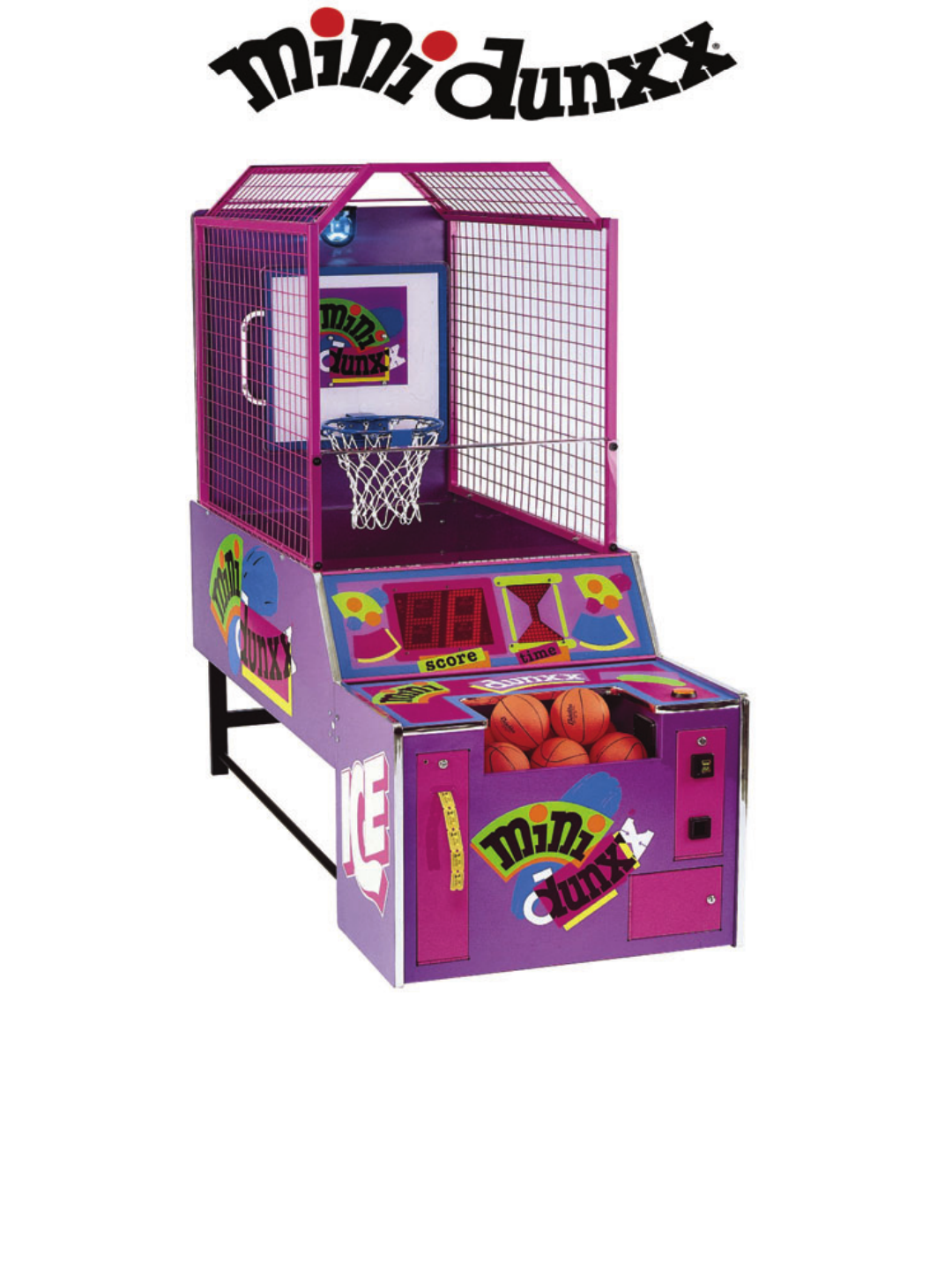
MINI DUNXX™ is the newest member to our coin-op
family of exciting basketball games and is designed
with young children in mind. As with our FULL
COURT FRENZY™ games, the basket moves,
adding excitement that only this basketball game
can provide.
MINI DUNXX™ utilizes state-of-the-art sound effects
to add to the excitement of game play. Blending
children’s voices with a catchy theme song makes a
combination that children really love.
The basket movement is controlled by a proven
gear-motor design, along with reliable sensing and
motor drive electronics.
Game set up is a snap. JUST PLUG IN AND PLAY.
Game design and graphics have been made
specifically with young children in mind. The game
height and ball return system have been made for
the smaller height of youngsters. The basketballs
that are used were selected because they’re easy
for children to pick up, and light enough for them to
throw. They are also soft, so they won’t cause
injuries.
The game has a fully adjustable ticket dispensing
feature with a ticket “cap” to allow the younger
children to get an ample amount of tickets, yet
prevent the older children from getting too many.
All game play features are adjustable, including:
game time, coins per play, and attract mode on/off
and length. It even comes with the option to allow
you to stop the basket from moving, if desired.
The control panel on the game has a unique timing
device. An electronic “hourglass” is utilized, being
easily identified and used by young children. An
oversized score display was also put in, for greater
appeal. The control panel is rounded out with the
use of bright colored shapes to add an eye-catching
look to the game.
MINI DUNXX™ uses a rotating beacon light to add
thrill to the game as points are earned. The operator
can adjust how often the light comes on. The light is
automatically activated during the attract mode.
Metal mesh is used on the sides and top of the
game for an attractive, long, maintenance free life.
GAME PLAY
The game begins when the player inserts money
into the game. When sufficient money is inserted
into the game to create 1 “credit”, the “Start” button
will flash on the game. (The game can store up to
99 credits, and can be set to play for 1-4 coins per
credit.)
Once the player presses the flashing “Start” button,
the game begins. The ball gate opens to release the
basketballs, and the whistle sounds to begin the
game.
Once the game begins, the hourglass display starts
the “sand” running, and the basket begins its first
movement.
As the game progresses, the basket will move every
few seconds, and stop in a new position.
As the players make baskets, the game will make a
“swish” sound, or one of the four phrases: “Alright!”,
“Yeah!”, “Awesome!”, or “Great Shot!” will be heard.
“New High Score!” will be heard if they break the
previous record.
Just before the game ends, the ball gate will close,
to capture the balls.
As the game ends, a horn sounds to signify the end
of the game, and the words “Game Over” can be
heard.
At this time, if your game is equipped with a ticket
dispenser, tickets will be awarded. The game is
then ready to be played again.
INTRODUCTION
3

DISASSEMBLY / RE-ASSEMBLY
THIS SECTION IS PROVIDED FOR YOU IN
THE UNLIKELY EVENT YOUR DOORWAY IS
SMALLER THAN STANDARD.
BEFORE YOU BEGIN
IMPORTANT: FAILURE TO FOLLOW THESE
DIRECTIONS CLOSELY COULD CAUSE SERIOUS
DAMAGE TO YOUR GAME.
WARNING: WHEN INSTALLING THIS GAME, A
3-PRONG GROUNDED RECEPTACLE MUST BE
USED. FAILURE TO DO SO COULD RESULT IN
SERIOUS INJURY TO YOURSELF OR OTHERS.
FAILURE TO USE A GROUNDED RECEPTACLE
COULD ALSO CAUSE IMPROPER GAME
OPERATION, OR DAMAGE TO THE
ELECTRONICS.
DO NOT DEFEAT OR REMOVE THE GROUNDING
PRONG ON THE POWER CORD FOR THE SAME
REASONS AS GIVEN ABOVE. USING AN
IMPROPERLY GROUNDED GAME COULD VOID
YOUR WARRANTY.
TOOLS NEEDED: Before you start, you will want
the following items:
• 7/16” Deep Well Socket
• 7/16” Combination Wrench
• Ratchet
• Small Allen Wrench (Supplied)
• Large Allen Wrench (Supplied)
• 1/4” Socket
REFER TO THE ILLUSTRATION IN THIS SECTION
TO HELP YOU IDENTIFY THE PARTS, AND HOW
THEY FIT TOGETHER.
DISASSEMBLY
(GAME IS TOO HIGH FOR YOUR
ENTRANCE)
NOTE: KEEP ALL HARDWARE WITH ITS
RESPECTIVE PART TO PREVENT ANY
CONFUSION DURING RE-ASSEMBLY.
1. Take off the mesh top enclosure by removing the
6 self-tapping screws holding it to the top of the
mesh sides. Additional pilot holes are provided
in the event that the holes currently being used
become stripped during re-assembly. A power
tool with a 1/4” socket is highly recommended if
new holes need to be used.
If the game is still too high, (and/or too wide,) to
pass through the entrance, refer to the following
disassembly procedure.
DISASSEMBLY
(GAME IS TOO WIDE FOR YOUR
ENTRANCE)
NOTE: KEEP ALL HARDWARE WITH ITS
RESPECTIVE PART TO PREVENT ANY
CONFUSION DURING RE-ASSEMBLY.
1. Remove the mesh top enclosure as described
previously.
2. Remove the clear plastic rebound guard on the
front of the game (4 bolts).
3. Remove the two mesh sides (4 bolts each).
4. Remove the rear access cover (4 Screws).
5. Unplug the mate lock connector and remove the
harness from the harness clips. Also, cut the tie
wraps securing the harness to the rear cabinet.
6. Remove the upper rear panel (4 bolts).
7. Remove the two black tubes connecting the leg
assembly to the front cabinet.
8. Remove the hardware connecting the two ball
return support brackets to the bottom of the ball
return (rear cabinet). It is not necessary to
remove these brackets from the back of the main
cabinet.
9. Disconnect the two pin connectors on the
ballgate motor, remove the tape securing the
harness to the ballgate motor, and cut the tie
wraps holding the harness to the underside of
the ball return.
10. Remove the hole plug for the latch key access
hole. Carefully disconnect the two cabinets by
opening the latches with the large shaped Allen
wrench on both sides and lowering the rear
cabinet to the floor.
11. Remove the rear leg assembly (4 bolts). (This
may not be necessary.)
12. Please follow the RE-ASSEMBLY instructions to
ensure proper installation.
4

DISASSEMBLY / RE-ASSEMBLY
RE-ASSEMBLY
1. To begin re-assembling your game, find an area
to assemble the game which is close to the final
location. Place something on the floor to protect
the game, (or use a carpeted area).
2. Locate the Ball Return Cabinet. (This is the
largest part of the game, and has an angled
panel in it. The Rear Cabinet).
3. Place the ball return on its side.
4. Locate the Lower Rear Leg Assembly, and
attach it to the Ball Return.
5. Position the Front Cabinet near the Ball Return.
Stand the Ball Return up and set the front end of
it on the two brackets located at the rear of the
Main Cabinet.
6. Locate the large “L” shaped Allen wrench,
commonly referred to as the ‘Latch Key’. Insert it
into the holes on the sides of the Ball Return.
Turn the Allen wrench until the Main Cabinet and
Ball Return lock together.
7. Install the hole caps into the holes on the sides
of the Ball Return.
8. Re-attach the ball return support brackets to the
bottom of the ball return.
9. Locate the (2) Cabinet Connecting Pipes, and
install them into the game. One end of the pipe
will have a threaded stud inserted into it. Screw
the stud into the holes located at the bottom rear
corners of the Main Cabinet.
10. Bolt the Connecting Pipes to the Lower Rear leg
Assembly.
11. Locate the Backboard Upper Rear Panel, and
attach it to the rear Ball Return. Be sure to
install the bolts so that the nuts are at the rear of
the panel.
12. Install the mesh frames to the Ball Return and
Backboard Upper Rear panel. Tighten Securely.
13. Install the rebound guard to the front of the mesh
frames. DO NOT OVER TIGHTEN.
14. Reconnect the harnessing to the bottom side of
the ball return, (the upper rear panel), and plug
in the mate lock connector.
15. Install the mesh top enclosure. If the original
holes are stripped, you will need a power tool
with a 1/4” socket to re-install the hardware in a
new hole. OVER TIGHTENING WILL CAUSE
THE SCREW HEADS TO BREAK OFF.
YOU ARE NOW READY TO PROCEED
TO THE “SET-UP / TESTING”
SECTION OF THIS MANUAL!
5

ASSEMBLY DIAGRAM
6

SET-UP / TESTING
SET-UP
IMPORTANT: FAILURE TO FOLLOW THESE
DIRECTIONS CLOSELY COULD CAUSE SERIOUS
DAMAGE TO YOU OR YOUR GAME.
BEFORE PLUGGING IN OR TURNING ON YOUR
GAME, MAKE SURE THE MAIN P.C. BOARD IS
SET TO THE PROPER VOLTAGE. LOOK AT THE
“VOLTAGE SELECTION” SWITCH ON THE P.C.
BOARD, AND VERIFY THE PROPER SETTING.
1. Plug the game into a grounded receptacle, and
turn on the game power. THE POWER SWITCH
IS LOCATED ON THE BACK OF THE FRONT
CABINET.
2. Check for anything unusual, including strange
sounds. If anything seems wrong, turn the game
off IMMEDIATELY.
3. Refer to the section below to determine the
proper settings for your game. After all
adjustments or selections have been made, you
are ready to play the game.
4. Before closing up the game, adjust the game
volume by using the adjustment knob located on
the Main P.C. Board.
PROGRAMMING BUTTONS
This section will give you a detailed explanation on
the functions of, and operating characteristics of
each of the programming buttons. Please read this
section carefully to avoid problems with your game.
PROGRAMMING BUTTON
(SW1)
This button is used to enter and exit the game
“Programming Mode.” Press this button once to
enter the mode. Once in this mode, you can use the
other buttons to change settings on the game.
Press this button once again, anytime you wish to
exit the “Programming Mode.”
SELECT BUTTON
(SW2)
This button is used to “select” the mode you wish to
change or modify. Each push of this button will
advance you to the next programming mode.
The “Hourglass” display is used to show you which
mode you are in. Rows of 2 L.E.D.’s are used for
each mode. Example: If 1 row of L.E.D.’s are lit, you
are in mode 1. If 2 rows are lit, you are in mode 2.
If 3 rows are lit, you are in mode 3, etc. The rows
run from top to bottom. Press the button repeatedly
to see how this works.
STEP BUTTON
(SW3)
This button is used to “Step” through the various
values that are set for each mode. Each push of the
button will raise whatever number is displayed.
These displayed values are shown in the large score
display. These numbers are the numbers actually
used, to change the way the game plays.
OPTION MODES
MODE 1
COINS PER CREDIT
(COIN 1)
This mode determines how many coins are needed
for 1 credit on the LEFT HAND COIN CHUTE. The
number displayed is how many coins it needs.
EXAMPLE: A setting of 2 would mean it would take
2 coins to get 1 credit or 1 game. The game default
value is “1” for 1 coin per credit.
MODE 2
COINS PER CREDIT
(COIN 2)
NOTE: THIS MODE IS NORMALLY RESERVED
FOR USE ON 1/2 PINT FRENZY OR SPECIAL
APPLICATION MINI DUNXX™ GAMES. IT IS NOT
USED FOR STANDARD MINI DUNXX™ GAMES.
This mode determines how may coins are needed to
create a credit on the RIGHT HAND COIN CHUTE.
This mechanism is set differently, so it can be used
for fractional credits. For normal use, set a “1” for
this mode. If you wish to use this for a coin with a
different value than that of coin mech. #1, contact
the I.C.E. service department for set-up information.
7

SET-UP / TESTING
MODE 3
ATTRACT MODE INTERVAL
This mode controls how often the “Attract” mode
comes on in this game. The Attract mode only
comes on when the game is not in use. When this
mode comes on, the game sounds are played and
the basket moves back and forth. This mode lasts
about 20 seconds. The time between Attract modes
can be set in 5 minute increments from 5 to 30
minutes. Setting a “0” turns the option off. The
factory default setting is “5”, for 5 minutes.
MODE 4
TIME PER CREDIT
This mode controls how long each game lasts. This
game can be adjusted from 20 to 45 seconds per
game, in 5 second increments. The factory default
setting for this option is “40” for 40 seconds.
MODE 5
JUST FOR PLAYING TICKETS
This option can be used in 2 ways. When any other
ticket options are enabled, this mode can be used to
give a player tickets, if they were unable to score
enough points to get tickets any other way.
If this option is used with all other ticket options
disabled, it can be used to payout XXX amount of
tickets, regardless of game score.
This option works by setting a number that relates to
how many tickets will be dispensed when one of the
above scenarios are used. Setting a “0” turns this
option off. The factory default setting for this option
is “3”, for 3 tickets.
MODE 6
POINTS PER TICKET
This mode determines how many points must be
scored for EACH ticket dispensed. This can be
adjusted from 1 to 20 points, in increments of 2
points. Setting a “0” turns this option off. The
factory default setting is 6, for 6 points per ticket.
MODE 7
TICKET THRESHOLD
This option makes it possible to dispense tickets
ONLY after the player has scored XXX amount of
points. This setting is adjustable from 0-20 points.
Setting a “0” turns this option off. The factory default
setting for this option is “0” for off.
MODE 8
ROTATING LIGHT INTERVAL
This mode controls how often the rotating lights
come on. Every time a player scores 3 points, the
game says something to the player. This option is
tied into when the game says something. The game
can be set for the lights to go on each time the game
says something, up to every 4th time the game says
something. Setting a “0” turns this option off. The
factory default setting is “2”, every 2nd time the
game says something.
MODE 9
MAXIMUM TICKETS
This option is used to limit the amount of tickets that
can be given at the end of the game. This option is
used to prevent older, more skilled children or
adults, from getting too many tickets from the game.
This limit can be set from 1-99 tickets. Setting a “0”
turns this option off. The factory default setting for
this option is “25” for a 25 ticket limit.
MODE 10
BASKET ON / OFF
This option is used to turn the movement of the
basket on or off. It may be desirable under certain
circumstances, to keep the basket from moving for
extremely young children. This option will allow you
to do this. We do however, recommend that you
keep the basket moving for greater player appeal.
Setting a “0” turns the basket off. The factory default
setting for this option is “1” for on.
MODE 11
ALARM MODE ON / OFF
This option allows the AUDIBLE TAMPER ALARM
to be turned on or off. Select a “0” to turn the alarm
mode off. Select a “1” to turn the alarm mode on.
The factory default setting is “1”.
TESTING
After set-up is complete, play a few games to verify
everything is working correctly. Pay special
attention to the Ball Gate, Basket Movement,
Scoring, and Score Displays.
8

MAINTENANCE
GENERAL MAINTENANCE
The MINI DUNXX™ Basketball game has been
engineered to be as maintenance free as possible.
There are, however, a few things you can do to keep
your game in top operating condition at all times.
Following the guidelines below will ensure a long,
trouble-free life for your game.
BASKETBALLS
The basketballs in this game should always be kept
inflated to the proper size. If the balls are too big or
small, they will not work properly in the game. Use
the inflation gauge supplied to keep the balls inflated
to the proper diameter.
The amount of balls is also VERY IMPORTANT to
play value in the game. Always keep at least 8 balls
in the game at all times. This ensures there are
always enough available during the game. It would
be a good idea to keep extra balls available to
replace worn or damaged balls. The balls can be
obtained easily through our Service Department at
(716) 759-0360.
TICKET DISPENSER
The Ticket Dispenser on the game is relatively
trouble-free, however cleaning the unit occasionally
from bits of ticket dust will keep the unit working
reliably. Use high-pressure air, (such as from an
aerosol can,) to blow dust build-up from the
mechanism and optical sensor. Clean the drive
wheels with an isopropyl alcohol,
COIN MECHANISM
The coin mechanism occasionally needs to be
cleaned to remove build-up of dirt and debris.
To clean mechanism, remove the coin mechanism
from the game and clean it with soapy water. Dry it
thoroughly and re-install. Test for proper operation.
GAME CABINET AND GRAPHICS
The game should be cleaned occasionally to keep it
bright and attractive looking. Clean the cabinet
sides with a good cleaner such as “Fantastik”® or
“409”® and a soft rag. Follow cleaning with a
furniture polish, such as Pledge®.
NOTE: DO NOT USE ALCOHOL, THINNERS OF
ANY KIND, OR PINBALL PLAY FIELD CLEANERS
ON ANY OF THE CABINET SURFACES
ESPECIALLY THE DECALS.
IF YOU HAVE ANY QUESTIONS OR COMMENTS
REGARDING INSTALLATION OR PROPER
FUNCTION OF YOUR GAME, PLEASE CALL OUR
SERVICE DEPARTMENT AT:
I.C.E. SERVICE DEPARTMENT
716-759-0360
NORMAL BUSINESS HOURS ARE:
MONDAY – FRIDAY, 9:00 AM TO 6:00 PM EST
9

MAINTENANCE
10
PROBLEM PROBABLE CAUSE SOLUTION
NO GAME POWER ON-OFF SWITCH ON THE GAME IS TURNED OFF
BLOWN A.C. POWER FUSE
GAME NOT PLUGGED IN OR CORD DAMAGED
BAD TRANSFORMER
TRANSFORMER HARNESS NOT CONNECTED
TURN POWER ON
REPLACE WITH PROPER FUSE
CHECK POWER CORD
CHECK PROPER VOLTAGES
CHECK HARNESS
GAME WILL NOT TAKE
MONEY OR GIVE CREDITS
CORRECTLY
BAD COIN SWITCH
GAME CREDITS SETTING INCORRECT
BAD COIN MECHANISM
LOOSE OR DAMAGED HARNESSING
BAD MAIN P.C. BOARD
CHECK W / METER AND REPLACE
CHECK MANUAL AND SET PROPERLY
ADJUST OR REPLACE
CHECK W / METER AND REPAIR
REPAIR OR REPLACE MAIN BOARD
BALLS GET STUCK IN GAME BALLS INFLATED TO WRONG SIZE
BALL GATE MOTOR BROKEN
BALL GATE DRIVER P.C. BOARD DEFECTIVE
BAD OR DISCONNECTED HARNESSING
BAD MAIN P.C. BOARD
USE INFLATION GAUGE SUPPLIED
REPAIR OR REPLACE MOTOR
REPLACE DRIVER P.C. BOARD
REPAIR OR REPLACE HARNESSING
REPAIR OR REPLACE MAIN BOARD
GAME WILL NOT START
WHEN PROPER CREDITS
ARE IN GAME
BAD START BUTTON MICRO SWITCH
BAD START BUTTON HARNESSING
BAD MAIN P.C. BOARD
GAME SET IN TEST MODE
REPLACE MICRO SWITCH
TEST AND REPAIR HARNESSING
REPAIR OR REPLACE MAIN BOARD
EXIT TEST & PROGRAMMING MODE
NO GAME SOUND BAD OR SHORTED SPEAKER
BAD SPEAKER HARNESSING
GAME SOUND TURNED OFF
REPLACE SPEAKER
TEST AND REPAIR HARNESSING
ADJUST VOLUME
NO SCORING
(NO SCORES ADDED)
BAD TRANSMITTER P.C. BOARD (NO TEST LEAD
ON RECEIVER)
BAD RECEIVER P.C. BOARD (TEST LIGHT
DOESN’T CHANGE)
BAD SENSOR HARNESSING
BAD MAIN P.C. BOARD
REPLACE TRANSMITTER
REPLACE RECEIVER
CHECK AND REPAIR HARNESSING
REPAIR OR REPLACE MAIN BOARD
SCORES INTERMITTENTLY BAD OR LOOSE HARNESSING
1/2 OF RECEIVER P.C. BOARD BAD (TEST EACH
RECEIVER)
NET TIE WRAPPED IN FRONT OF I.R.
TRANSMITTER
REPAIR OR REPLACE HARNESSING
REPAIR OR REPLACE P.C. BOARD
MOVE NETTING FROM SENSOR
NO SCORING
(SCORES BUT NOT
DISPLAYED)
BAD OR INTERMITTENT DISPLAY HARNESSING
BAD SCORE DISPLAY
BAD MAIN P.C. BOARD
REPAIR HARNESSING
REPAIR / REPLACE SCORE DISPLAY
REPAIR OR REPLACE MAIN BOARD
BASKET DOES NOT MOVE
CORRECTLY
BAD ROTARY MOTOR
LOOSE OR WEAK CLUTCH
BAD OR IMPROPERLY ALIGNED ENCODER P.C.
BOARD
BAD ENCODER DECAL
BAD HARNESSING
BAD MAIN P.C. BOARD
GAME OPTION SET TO NON-MOVING VERSION
REPLACE MOTOR
TIGHTEN OR REPLACE CLUTCH
ADJUST OR REPLACE ENCODER P.C.
BOARD
CHECK FOR SCRATCHES & REPLACE
CHECK AND REPAIR HARNESSING
REPAIR OR REPLACE MAIN BOARD
CHANGE PROGRAM SETTING
GAME DOES NOT
DISPENSE TICKETS
PROPERLY
OUT OF TICKETS
LOOSE OR BAD HARNESSING
BAD TICKET DISPENSER
TICKETS JAMMED
BAD MAIN P.C. BOARD
TICKET OPTION NOT SET CORRECTLY
ADD TICKETS TO DISPENSER
CHECK AND REPAIR HARNESSING
REPLACE DISPENSER
CLEAR TICKET JAM
REPAIR OR REPLACE MAIN BOARD
ADJUST OPTIONS CORRECTLY
ROTATING LIGHTS DO NOT
WORK PROPERLY
BAD BULB IN ROTATING LIGHT
BAD MOTOR IN ROTATING LIGHT
BAD GAME OR LIGHT HARNESSING
HARNESSING NOT PLUGGED IN
BAD MAIN P.C. BOARD
REPLACE LIGHT BULB
REPLACE ROTATING LIGHT
CHECK AND REPAIR HARNESSING
CHECK CONNECTIONS
REPAIR OR REPLACE MAIN BOARD
QUICK TROUBLESHOOTING

MAINTENANCE
PROBLEM PROBABLE CAUSE SOLUTION
NO GAME FUNCTIONS
(GENERAL)
BAD A.C. OR D.C. FUSES
CONNECTORS BAD OR NOT FULLY INSTALLED
SHORTED COMPONENT IN GAME
CHECK AND REPLACE FUSES
CHECK CONNECTORS
CHECK ALL PCB’S AND HARNESSES
START BUTTON WILL NOT
FLASH
BAD LIGHT BULB
BAD OR INTERMITTENT HARNESSING
BAD MAIN P.C. BOARD
REPLACE LIGHT BULB
CHECK AND REPAIR HARNESSING
REPAIR OR REPLACE MAIN BOARD
BASKETBALL LIGHTS WILL
NOT LIGHT
BAD LIGHT BULB
BAD OR INTERMITTENT HARNESSING
BAD MAIN P.C. BOARD
REPLACE LIGHT BULB
CHECK AND REPAIR HARNESSING
REPAIR OR REPLACE MAIN BOARD
ALARM SOUNDS
FREQUENTLY
BAD I.R. TRANSMITTER
BAD I.R. RECEIVER
BAD MAIN P.C. BOARD
NETTING IN FRONT OF TRANSMITTER
BAD OR SHORTED HARNESSING
REPLACE I.R. TRANSMITTER
REPLACE I.R. RECEIVER
REPAIR OR REPLACE MAIN BOARD
MOVE NETTING FROM SENSOR
CHECK AND REPAIR HARNESSING
ATTRACT MODE DOES NOT
WORK CORRECTLY
GAME OPTIONS SET IMPROPERLY
RESET GAME PROGRAMMING
QUICK TROUBLESHOOTING
11

MECHANICAL REPAIR
OPERATIONAL BACKGROUND
The following will outline the basic operating principles
of the MINI DUNXX™ Basketball game.
The movement of the MINI DUNXX™ Basketball
game hoop is operated through a gear motor control
that moves the basket assembly back and forth. This
is a 12 volt gear motor that has power to it applied
and reversed by the game electronics.
It is useful to know that power to the gear motor is
chopped through the game software to allow software
control of the motor speed. The motors are run at a
50% duty cycle. This is important to know if the
circuitry is being analyzed by oscilloscope. Direction
of the gear motor is achieved by reversing power.
The electronics have built-in dynamic braking to stop
the motor quickly.
The positioning of the basket assembly is
accomplished through an optical encoding system.
The system uses a decal with alternating reflective
and non-reflective surfaces as a medium for the optic
L.E.D.’s. A system of 3 L.E.D.’s are used to
determine position of the backboard. The high / low
pulses sent out by the encoder P.C. Board are
received and interpreted by the Main P.C. Board.
These signals are then converted to commands by
the software, depending upon game conditions. This
type of operating system allows limitless control by
software design, allowing easy repairs of the game in
the field, thus avoiding expensive and sometimes
difficult mechanical field modifications.
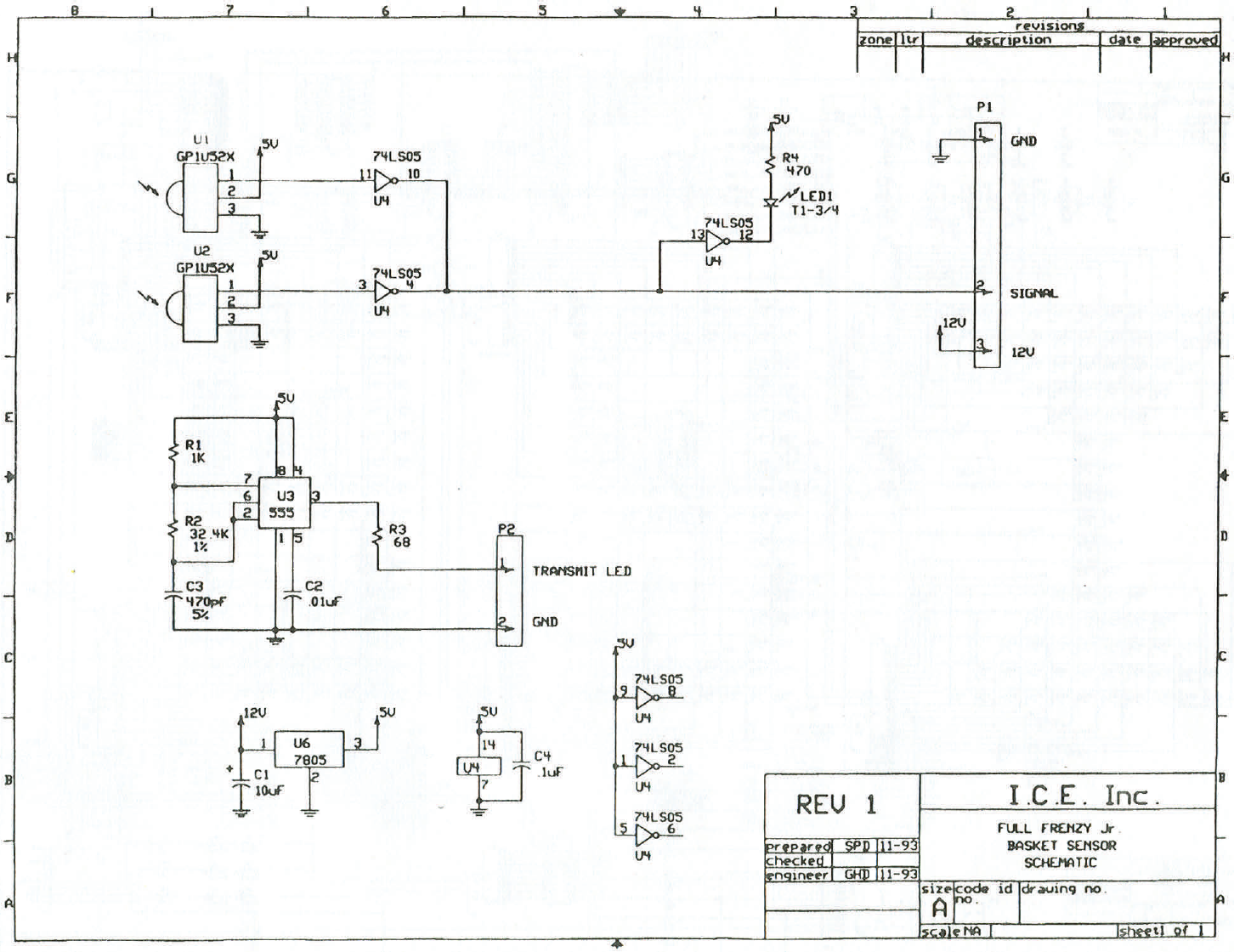
The game also uses reliable optical detectors for ball
sensing. This creates a sensing system that has a
much longer life span than its mechanical
counterparts. The Receiver P.C. Board receives a
pulsed light beam from the Emitter P.C. Board at a
specified frequency. This helps eliminate background
electronic noise that could cause interference. The
receiver L.E.D.’s incorporate automatic gain control to
consistently adjust to changing environmental
circumstances.
The ball gate system on the game is operated by a
rotational gearbox. The Driver P.C. Board flip-flops
incoming D.C. power to operate the unit. Operating
the D.C. power with one polarity opens the ball gate.
Reversing polarity causes the ball gate to close. The
reversing of current is accomplished through a
combination of hardware and software from the
game’s Main P.C. Board.
The following sections will give you detailed
information on repair, replacement, and adjustment
of the game’s components.
MECHANICAL REPAIR
WARNING: ALWAYS REMOVE POWER TO THE
GAME, BEFORE ATTEMPTING ANY SERVICE,
UNLESS NEEDED FOR SPECIFIC TESTING.
FAILURE TO OBSERVE THIS PRECAUTION
COULD RESULT IN SERIOUS INJURY TO
YOURSELF OR OTHERS.
BALL GATE
BALL GATE REMOVAL
Ball gate removal is accomplished in the following
order:
1. Turn off all power to the game and remove the
A.C. Power Cord.
2. Climb into the game and unplug the 2 pin
connectors that are attached to the Ball Gate
Driver P.C. Board.
3. Cut the tie wrap that secures the harness to the
Ball Gate Motor.
4. Loosen the (2) Allen Head screws that are on
the Ball Gate on the opposite side of the motor.
5. Push the shaft at the end of the ball gate into the
gate, and the entire assembly can now be
removed.
PLEASE NOTE: THE THREAD LOCKING
COMPOUND USED TO SECURE THE SHAFT TO
THE BALL GATE MAY PREVENT THE SHAFT
FROM SLIDING INTO THE BALL GATE EASILY.
USE A PAIR OF PLIERS (IF NECESSARY) TO
TURN THE SHAFT IN TO THE BALL GATE.
THE BLACK VELCRO POSITIONED ON THE END
OF THE BALL GATE IS USED TO PREVENT THE
OPTICAL ENCODER CLOSEST TO THE MOTOR
SHAFT FROM REFLECTING ON TO THE END OF
THE BALL GATE, WHEN IN THE CLOSED
POSITION. THIS MUST BE LOCATED RIGHT UP
AGAINST THE MOTOR SHAFT FOR THE BALL
GATE MECHANISM TO WORK PROPERLY.
PLEASE DO NOT REMOVE THIS VELCRO STRIP
FROM THE SHAFT, EXCEPT TO REPLACE IT.
12

MECHANICAL REPAIR
BALL GATE DRIVER
P.C. BOARD REMOVAL
1. Loosen the (2) Allen Head screws that hold the
Ball Gate to the Ball Gate Motor.
2. Remove the (2) screws and star washers that
hold the P.C. Board to the motor.
3. Unsolder the wires from the motor. NOTE:
REMEMBER WHICH WAY THE WIRES ARE
ATTACHED TO THE MOTOR.
4. Check the motor for proper operation. This can
be done by hooking it up to any 5-12 volt D.C.
power source and checking for smooth rotation
without any binding or skipping.
5. Check the Ball Gate Driver P.C. Board for proper
operation. (For details on testing, refer to the
electronics section of this manual.)
IMPORTANT: WHEN RE-ASSEMBLING THE BALL
GATE ASSEMBLY, IT IS NECESSARY TO KEEP A
SPACING OF 3/16” TO 1/4” BETWEEN THE BALL
GATE AND THE EDGE OF THE OPTICAL
ENCODERS. IF THESE ARE SPACED
IMPROPERLY, THE SENSORS WILL NOT WORK
PROPERLY AND THE BALL GATE WILL EITHER
CONTINUE TO ROTATE OR STOP IN STRANGE
POSITIONS.
BE SURE THE OPTICAL ENCODERS FACE
STRAIGHT UP ON THE P.C. BOARD, AND ARE
NOT BENT OVER TOWARDS THE MOTOR
SHAFT. IF THE ENCODERS ARE BENT
TOWARDS THE SHAFT, THE BALL GATE WILL
CONTINUE TO RUN.
BACKBOARD SERVICE
ENCODER P.C. BOARD
The Encoder P.C. Board may be serviced by
removing the backboard from the game.
1. Remove the backboard from the game by
removing the (4) Phillips head bolts that hold the
backboard to the Motor Housing.
2. Remove the (2) hex spacer nuts that hold the
Encoder P.C. Board to the Motor Housing.
3. Remove the connector from the Encoder P.C.
Board. Please be sure the connector is installed
the same way when re-assembling the game.
MOTOR HOUSING REMOVAL
It is necessary to remove the Backboard to service
the Gear Motor or Clutch Assembly.
1. Remove the (4) Phillips head bolts that hold the
Motor Housing to the Backboard.
DO NOT PULL THE ASSEMBLY AWAY FROM THE
REAR OF THE GAME UNTIL THE HARNESSING
HAS BEEN DISCONNECTED.
MOTOR OR CLUTCH REMOVAL
1. Unplug the (3) single pin connectors for the
score sensor. (Make sure when you re-connect
them, that you match the wire colors).
2. Remove the (3) Allen Head screws that hold the
Backboard Mounting Bracket to the Clutch.
3. Remove the (1) Allen Head Shoulder Bolt that
holds the Backboard Bearing to the Motor
Housing.
4. Slide the Backboard Mounting Bracket off of the
Motor Housing and Clutch.
5. If removing the Clutch, remove the (2) Allen
Head Set Screws that hold the Clutch to the
motor shaft, as well as the “E” clip. Pull the
Clutch off of the motor shaft using a twisting
motion.
13

ELECTRONIC REPAIR
The following section will describe repair procedures
and trouble shooting hints for the game electronics.
Please read the section “Operational Background”
located in the “Mechanical Repair” section of this
manual. This will give you a good idea of the
game’s overall operating parameters.
WARNING: EXERCISE CAUTION WHENEVER
WORKING WITH ELECTRONICS, AS THEY CAN
BE VERY SUSCEPTIBLE TO DAMAGE FROM
SHORT CIRCUITING OR PHYSICAL ABUSE.
ALWAYS UNPLUG THE GAME WHEN WORKING
ON HIGH VOLTAGE AREAS OF THE GAME,
SUCH AS THE TRANSFORMER OR MONITOR.
USE EXTREME CAUTION WHEN USING VOLT
METERS TO DO CIRCUIT CHECKS IF THE GAME
POWER HAS BEEN LEFT ON.
WHEN USING A VOLT METER, BE SURE IT IS
SET TO THE CORRECT VOLTAGE OR
RESISTANCE RANGE, BEFORE USING. THIS
CAN PREVENT POSSIBLE DAMAGE TO THE P.C.
BOARD OR MISDIAGNOSIS.
ALWAYS REMOVE POWER TO THE GAME WHEN
PLUGGING OR UNPLUGGING P.C. BOARDS.
IT IS NECESSARY TO USE I.C.E. REPLACEMENT
PARTS TO CONTINUE WARRANTY COVERAGE.
USE OF NON-I.C.E. APPROVED PARTS WILL
NOT ONLY VOID YOUR WARRANTY, BUT COULD
CAUSE SERIOUS HARM TO THE GAME OR
CAUSE SERIOUS BODILY INJURY.
IF YOU HAVE ANY QUESTIONS REGARDING
REPAIR AFTER READING THIS SECTION, CALL
OUR SERVICE DEPARTMENT AT (716) 759-0360
BEFORE PROCEEDING.
FUSES
Fuses are the first thing that should be checked
when the game either appears not to work, or
appears to work incorrectly.
There are 3 fuses in this game. The fuses are
located on the Main P.C. Board. 2 of the fuses are
for low voltage D.C., and are exposed on the P.C.
Board. One of the fuses is for high voltage A.C.,
and is in an insulated housing.
To check or service the fuses, FIRST REMOVE THE
POWER CORD FROM THE WALL OUTLET.
FAILURE TO REMOVE THE POWER CORD
COULD RESULT IN SERIOUS INJURY OR
DEATH. Using a small flat blade screwdriver, pry
the fuse from the fuse holder, or turn the cap off of
the fuse holder, and remove the fuse.
NOTE: ALWAYS TEST THE FUSE WITH A VOLT
METER, EVEN IF THE FUSE LOOKS GOOD.
THERE SHOULD BE NO RESISTANCE NOTED
WHEN TESTING FOR CONTINUITY. THIS TEST
MUST BE PERFORMED, AS CERTAIN TYPES OF
FUSES HAVE THE POTENTIAL TO ONLY BLOW
PARTIALLY, GIVING THE APPEARANCE OF
WORKING FINE, UNTIL A LOAD IS PLACED ON
THEM.
Replace the Main P.C. Board fuses with the original
type and value. USE SLO-BLO MDQ TYPE fuses
only. Other types of slo-blo fuses may cause
strange problems with the game.
CHANGING A.C. VOLTAGES
Voltages are easily changed on the Main P.C.
Board. A convenient voltage selection switch is
mounted towards the center of the board. Be sure
of the voltage you require, and simply slide the
switch to the correct voltage setting.
MAIN P.C. BOARD
IMPORTANT: BEFORE REMOVING THE MAIN
P.C. BOARD FOR SERVICE OR REPLACEMENT,
RECORD ALL INFORMATION REGARDING
CUSTOM OPTION SETTINGS, SO THESE
SETTINGS CAN BE RE-INSTALLED LATER IF
NECESSARY.
The Main P.C. Board is located inside the Main
Cabinet beneath the ball tray.
When performing service on the Main P.C. Board, it
is a good idea to remove the board when replacing
even socketed or snap-in components. This can
avoid any possible costly errors that may occur
otherwise.
Remove the Main P.C. Board in the following
manner:
1. Remove all A.C. Power to the game. (REMOVE
THE POWER CORD FROM THE A.C.
RECEPTACLE.)
2. Disconnect all Mate-Lock connectors from the
game.
14

ELECTRONIC REPAIR
3. Remove the (6) plastic nuts the retain the P.C.
Board to the mounting bracket.
4. Carefully remove the Main P.C. Board
5. Re-assemble in reverse order.
BALL SENSORS
It is not necessary to remove the hoop from the
backboard to service the ball sensors. This
operation can be easily accomplished while still on
the game.
1. Remove power to the game to prevent damage
to the electronics when connecting or
disconnecting game harnessing.
2. Try to determine which sensor is at fault, Emitter
or Receiver. This can be determined as follows:
a) If pilot L.E.D. on receiver is lit brightly,
and intensity doesn’t change regardless
of blocking the Emitter, the Receiver is
probably bad.
b) If pilot L.E.D. flashes when the receiver is
blocked, but score is not seen during
game play and harnessing proves good,
the Receiver is probably bad.
c) If pilot L.E.D. is lit dimly, or strobes dimly,
the Emitter is probably bad.
To change the Emitter:
a) Remove the Emitter and Receiver
covers.
b) Unplug the Emitter harness from the
Receiver (closest to the backboard.)
c) Remove the Emitter harness from the
hoop. REMEMBER HOW TO ROUTE
THIS HARNESS WHEN INSTALLING
THE NEW EMITTER.
d) Remove the plastic retaining nuts.
e) Re-assemble in reverse order.
To change the Receiver:
a) Remove the receiver cover.
b) Remove the (3) single pin connectors
from the motor harness to the Receiver.
c) Unplug the Emitter harness from the
Receiver.
d) Remove the plastic nuts that retain the
Receiver to the housing.
e) Re-assemble in reverse order.
REMEMBER TO CONNECT THE HARNESSING
TO THE STRAIN RELIEF TO KEEP THE
HARNESSING FROM FALLING DOWN INTO AN
AREA WHERE THE BALLS COULD HIT IT.
SCORE DISPLAY P.C. BOARD
The score display can be serviced as follows:
a) Remove all A.C. power from the game.
b) Remove the (3) Allen Head screws that
hold the retaining bracket for the score
display, and remove the bracket.
c) Lift the control panel containing the score
display from the game.
d) Disconnect the harnessing from the score
display.
e) Remove the (8) plastic nuts that retain
the display to the control panel.
f) Re-assemble in reverse order.
15

PARTS LISTINGS
MECHANICAL PARTS
MD1001 Control Panel Housing
MD1002 Control Panel Retainer
HP1003 Backboard Mounting Bracket
HP1004 Motor Housing
HP1006 Cabinet Connecting Pipes
MD1007 I.R. Emitter Cover
MD1008 I.R. Receiver Cover
HP1009 Motor Shield
MD1011 Mesh Frame
HP1023 Ball Gate Shaft
BB1034 Clutch (XIC-1803)
MD1039A Hoop, Fabricated & Painted
HP3001 Basketballs
MD3002 Backboard, Printed & Fabricated
HP3003 Ball Gate Bearing
MD3005 Control Panel, Printed & Fabricated
BB3008 Basketball Net
HP3013 Backboard Mtg. Bracket, Nylon Plastic
MD3014 Main Cabinet
MD3015 Ball Return Cabinet
MD3017 Rebound Guard
FP3057 Upper Flipper Cover
5001 Coin Door, Over - Under
PC50507 Speaker Grill
MD1022 Ball Gate
DECALS & GRAPHICS
HP7001 Programming Decal
MD7001 Decal (MD Cabinet Top)
MD7002 Decal (MD “ICE”)
MD7003 Decal (MD Rear Cabinet)
MD7004 Decal (MD Front Cabinet)
HP7010 Encoder Decal (for rotation)
MD9001 Service Manual
HARDWARE
3052 Hole Plug
6103 Latch (2-67-0055-02)
6104 Latch Receptacle (2-67-0002-02)
6105 Latch Tool (2-75-0059-02)
655s #8 x 5/8” Square Drive Screw
PC60601 1/4-20 x 5/8” Allen Head Bolt, Black
3036 Black Plastic Washer
6106 5/16 x 1/2” Shoulder Bolt
PC60641 6-32 x 5/8” Plastic Hex Spacer
PC60642 6-32 x 3/8” Plastic Hex Spacer
PC60643 6-32 x 1/4” Plastic Hex Spacer
644P 6-32 x 1/2” Plastic Hex Spacer
PC60631 1/4-20 Cabinet Insert
6051 1/4-20 x 1” Phillips Head Bolt
MD3027 1” x 2” Black Tube Cap
ELECTRICAL PARTS
HP2005 Basketball Push Button w/ “Start”
2007 Speaker
MD2008X Ball Gate Motor
HP2009X Rotary Motor
PC20224 12volt Counter
BT2027X 20Ft. Line Cord
2364 12volt Fan
ELECTRONIC PARTS
HP2000X Display P.C. Board
HP2001X Main P.C. Board
MD3004X Net Sensor Prior to April 2007
E00210MDX Net Sensor After March 2007
BB2014X FCF Position Encoder P.C. Board
HP2029X Ball Gate P.C. Board
16
17
18
19

Contacts at SEGA
Machine Sales
Telephone: +44 (0) 208 391 8090
Fax: +44 (0) 208 391 8099
www.sega-amusements.co.uk
SEGA Spares
Telephone: +44 (0) 208 391 8060
Fax: +44 (0) 208 391 8096
www.segatotalsolutions.com
Customer Services
Telephone: +44 (0) 208 391 8065
Fax: +44 (0) 208 391 8096
