Arcade Mushi King Manual P User
Sega_Mushi_King_English_Manual Sega_Mushi_King_English_Manual
2013-11-21
User Manual: Arcade Mushi King Manual
Open the PDF directly: View PDF ![]() .
.
Page Count: 61

「Mushiking#1-eng.doc」 最終印刷日時:2010/01/14 14:16:00
1/27
“MUSHIKING” (Owner’s Manual - 1/3) = 2004/05/14
(Front Cover)
(ロゴ)
OWNER’S MANUAL
(筐体切抜き、 画面はめ込み)
(US/ASIA 向け)
(STOP) IMPORTANT
● Before using this product, read this manual carefully to understand the
contents herein stated.
● After reading this manual, be sure to keep it available nearby the product or
elsewhere convenient for referring to it anytime when necessary.

「Mushiking#1-eng.doc」 最終印刷日時:2010/01/14 14:16:00
2/27
(Back Cover)
SEGA CORPORATION
12-14, Higashikohjiya 2-Chome, Ohta-ku, Tokyo 144-8532, Japan
Phone: +81-3-5737-7544 Facsimile: +81-3-5737-7746
1ST
PRINTING © SEGA CORPORATION, 2003, 2004
MANUAL NO. 420-6812-01
(P. i)
TABLE OF CONTENTS
【本文に合わせる】
E0-0405 420-6812-01

「Mushiking#1-eng.doc」 最終印刷日時:2010/01/14 14:16:00
3/27
(P. ii)
INTRODUCTION
This manual is intended to provide detailed descriptions together with all the necessary information
covering the general operation of electronic assemblies, electro-mechanicals, servicing control, spare parts,
etc. for the product, "MUSHIKING – The King of Beetle".
This manual is intended for the owners, personnel and managers in charge of operation of the product.
Operate the product after carefully reading and sufficiently understanding the instructions.
In the unlikely event that the product does not function correctly, DO NOT allow anyone other than a
technician to touch the internal system. Turn off the power to the machine, making sure to unplug the
electrical cord from the outlet, and contact the office listed below or the point-of-purchase for this product.
Use of this product is unlikely to cause physical injuries or damage to property. However, points that
require special attention are indicated by thick underlining, the word "IMPORTANT" and the symbol below.
(STOP) IMPORTANT
Indicates important information that, if ignored, may result in the mishandling of
the product and cause faulty operation or damage to the product.
SEGA ENTERPRISES, INC. (U.S.A.)/CUSTOMER SERVICE
45133 Industrial Drive, Fremont, California 94538, U.S.A.
Phone: (415) 701-6580
Facsimile: (415) 701-6594
SPECIFICATIONS
Installation space: 452 mm (17.8 in.) [Width] x 610 mm (24.0 in.) [Depth]
Height [POP assembled]: 1,280 mm (50.4 in.); [1,590 mm (62.6 in.)]
Weight: 75 kg (165.3 lbs.)
Power, maximum current: 102 W, 1.4 A (AC 120 V, 60 Hz Area)
103 W, 0.8 A (AC 220 V, 50 Hz Area)
??? W, 0.0 A (AC 220 V, 60 Hz Area)
??? W, 0.0 A (AC 240 V, 50 Hz Area)
Power, current: ??? W, 0.0 A, (Max.) (AC 110 V, 60 Hz) <TAIWAN>
??? W, 0.0 A, (Min.) (AC 110 V, 60 Hz) <TAIWAN>
Card capacity: 600 (Max.)
Monitor: 14 Type Color Monitor

「Mushiking#1-eng.doc」 最終印刷日時:2010/01/14 14:16:00
4/27
(P. iii)
Definition of 'Site Maintenance Personnel or Other Qualified Individuals'
[!] WARNING
Procedures not described in this manual or marked as 'to be carried out by site
maintenance personnel or other qualified professionals' should not be carried
out by personnel without the necessary skill or technology. Work carried out by
unqualified persons may cause serious accidents, including electrocution.
Parts replacement, maintenance inspections and troubleshooting should be carried out by site maintenance
personnel or other qualified professionals. This manual includes directions that potentially dangerous
procedures should only be carried out by professionals with the appropriate specialized knowledge.
The 'site maintenance personnel or other qualified professionals' mentioned in this manual are defined as
follows:
Site maintenance personnel:
Individuals with experience in maintaining amusement equipment, vending machines, etc., working under
the supervision of the owner/operator of this product to maintain machines within amusement facilities or
similar premises by carrying out everyday procedures such as assembly, maintenance inspections, and
replacement of units/expendable parts.
Activities to be carried out by site maintenance personnel:
Amusement equipment/vending machine assembly, maintenance inspection and replacement of
units/expendable parts.
Other qualified professionals:
Persons employed by amusement equipment manufacturers, or involved in design, production, testing or
maintenance of amusement equipment. The individual should have either graduated from technical school
or hold similar qualifications in electrician/electronics/mechanical engineering.
Activities to be carried out by other qualified professionals:
Amusement equipment/vending machine assembly, repair/adjustment of electrical/electronic/mechanical
parts.
「Mushiking#1-eng.doc」 最終印刷日時:2010/01/14 14:16:00
5/27
(P. 1)
1. HANDLING PRECAUTIONS
When installing or inspecting the machine, be very careful of the following points and pay attention to
ensure that the player can enjoy the game safely.
Non-compliance with the following points or inappropriate handling running counter to the cautionary
matters herein stated can cause personal injury or damage to the machine.
[!] WARNING
● Before performing work, be sure to turn power off. Performing the work without
turning the power off can cause electric shocks or short circuits. In the case that
work should be performed with the power ON, this will be clearly stated in the
manual.
● To avoid electric shocks and short circuits, do not plug in or unplug the
machine too quickly.
● To avoid electric shocks, do not plug in or unplug the machine with wet hands.
● Do not leave power cords and earth wires exposed on the surface (floor,
passage, etc.). If exposed, the power cords and earth wires are susceptible to
damage. Damaged cords and wires can cause electric shocks or short circuits.
● To avoid causing a fire or electric shock, do not put things on or damage
power cords.
● During or after installation of the product, do not unnecessarily pull the power
cord. If damaged, the power cord can cause a fire or electric shock.
● In case the power cord is damaged, ask for replacement from the point-of-
purchase or the office herein stated. Using a damaged cord can cause fire,
electric shock or leakage.
● Be sure to perform grounding appropriately. Inappropriate grounding can
cause electric shocks.
● Be sure to use fuses meeting the specified rating. Using fuses exceeding the
specified rating can cause a fire or electric shock.
● Ensure that connectors for IC BD and others are properly inserted. Insufficient
insertion can cause an electric shock.
● Specification changes, removal of equipment, conversion and/or additions
not designated by SEGA are not permitted.
- Failure to observe this may cause a fire or an electric shock. Non-
compliance with this instruction can have a bad influence upon the physical
condition of the players or the onlookers, or result in injury during play.
- SEGA shall not be held responsible for damage, or compensation for
damage to a third party, caused by specification changes not designated by
SEGA.
「Mushiking#1-eng.doc」 最終印刷日時:2010/01/14 14:16:00
6/27
● Be sure to perform the periodic maintenance inspections herein stated.
(STOP) IMPORTANT
● For the IC board circuit inspections, only the logic tester is allowed. The use of
a multiple-purpose tester is not permitted, so be careful in this regard.
● When cleaning the CRT surfaces, use a soft and dry cloth. Do not apply
chemicals such as thinner, benzine, etc.
● Static electricity from your body may damage some electronics devices on
the IC board. Before handling the IC board, touch a grounded metallic surface
so that the static electricity can be discharged.
● Do not turn the power on and off continuously. Repeatedly turning the power
on and off may cause product malfunction or parts damage.
● Some parts are not specifically designed and manufactured for this game
machine. The manufacturers may discontinue, or change the specifications of,
such general-purpose parts. If this is the case, SEGA cannot repair or replace the
damaged game machine, whether or not the warranty period has expired.
(P.3)
CONCERNING THE STICKER DISPLAY
This SEGA product has stickers attached describing the product manufacture No. (Serial No.) and
Electrical Specifications. It also has a Sticker describing where to contact for repair and for purchasing
parts.
When inquiring about or asking for repairs, mention the Serial No. and Name of Machine indicated on the
Sticker. The Serial Number indicates the product register. Identical machines could have different parts
depending on the date of production. Also, improvements and modifications might have been made after
the publication of this manual. In order to ensure you order the correct parts, mention the Serial No. when
contacting the applicable places.
CONCERNING WARNING DISPLAYS
This SEGA product has warning displays on stickers, labels and/or printed instructions adhered/attached to
or incorporated in the places where a potentially hazardous situation could arise. The warning displays are
intended for accident prevention for customers and for avoiding hazardous situations relating to
maintenance and servicing work. Some portions of the cabinet contain high voltage and may cause
accidents if touched. When performing maintenance, be very careful of the warning displays. It is
especially important that any complex repair and replacement work not mentioned herein should be
performed by those technical personnel who have knowledge of electricity and technical expertise.
In order to prevent accidents, caution any customer ignoring the warnings to cease and desist immediately.
FIG. 1
1) Serial No. Display
「Mushiking#1-eng.doc」 最終印刷日時:2010/01/14 14:16:00
7/27
2) Electrical Specifications Display
(P. 4)
2. PRECAUTIONS REGARDING INSTALLATION
LOCATION
[!] WARNING
This product is an indoor game machine. Do not install it outside. Even indoors,
avoid installing in places mentioned below so as not to cause a fire, electric
shock, injury and/or malfunction.
- Places subject to rain or water leakage, or places subject to high humidity in
the proximity of an indoor swimming pool and or shower, etc.
- Places subject to direct sunlight, or places subject to high temperatures in the
proximity of heating units, etc.
- Places filled with inflammable gas or vicinity of highly inflammable/volatile
chemicals or hazardous matter.
- Dusty places.
- Sloped surfaces.
- Places subject to any type of violent impact.
- Vicinity of anti-disaster facilities such as fire exits and fire extinguishers.
- The operating (ambient) temperature range is from 5℃ to 30℃.
2-1 LIMITATIONS OF USAGE
[!] WARNING
● Be sure to check the Electrical Specifications. Ensure that this product is
compatible with the location's power supply, voltage and frequency
requirements. A plate describing Electrical Specifications is attached to the
product. Non-compliance with the Electrical Specifications can cause a fire and
electric shock.
● This product requires a breaker and earth mechanism as part of the location
facilities. Using the product without these can cause a fire and electric shock.
● Ensure that the indoor wiring for the power supply is rated at 7A or higher (AC
single phase 100V ~ 120V area), and 4A or higher (AC 220V ~ 240V area). Non-
compliance with the Electrical Specifications can cause a fire and electric shock.
● Be sure to use an independent power supply equipped with a surge-
suppressor. Using a power supply without a surge-suppressor can cause an
「Mushiking#1-eng.doc」 最終印刷日時:2010/01/14 14:16:00
8/27
outbreak of fire if a power surge occurs.
● Putting many loads on one electrical outlet can cause generation of heat and
a fire resulting from overload.
● When using an extension cord, ensure that the cord is rated at 7A or higher
(AC 100V ~ 120V area) and 4A or higher (AC 220V ~ 240V area). Using a cord
rated lower than the specified rating can cause a fire and electric shock.
(P. 5)
2-2 OPERATION AREA
[!] WARNING
● For the operation of this machine, secure a minimum area of 0.75 m (W) x 1.2
m (D). In order to prevent injury resulting from falls/accidents during game play,
be sure to secure the minimum area for operation.
● Be sure to provide sufficient space (150 mm minimum) so as to allow this
product's ventilation fan to function efficiently. To avoid machine malfunctions or
fires, do not place any obstacles near the ventilation opening.
● Do not allow objects to block the ventilation ports. It can cause generation of
heat and a fire.
● SEGA shall not be held responsible for damage or compensation for damage
to a third party, resulting from the failure to observe this instruction.
1) 0.75 m (29.5 in.) 1.2 m (47.2 in.) 0.46 m (18.1 in.) 1.8 m (70.9 in.)
2) Ventilation Space: 150 mm (5.9 in.) minimum
(STOP) IMPORTANT
In order to transport the machine into a building, the minimum necessary
dimensions of the opening (of doors, etc.) are 0.5 m (19.7 in.) [W] and 1.3 m (51.2
in.) [H].
Electricity Consumption:
MAX. 0.0 A (AC 120 V, 60 Hz)
MAX. 0.0 A (AC 220 V, 50 Hz)
MAX. 0.0 A (AC 220 V, 60 Hz)
MAX. 0.0 A (AC 240 V, 50 Hz)
MAX. 0.0 A (AC 110 V, 60 Hz) <TAIWAN>
(P. 7)
「Mushiking#1-eng.doc」 最終印刷日時:2010/01/14 14:16:00
9/27
3. PRECAUTIONS REGARDING PRODUCT
OPERATION
3-1 BEFORE OPERATION
To avoid injury and trouble, be sure to pay attention to the behavior of visitors and players.
[!] WARNING
In order to avoid accidents, check the following before starting the operation:
● To ensure maximum safety for the players and the customers, ensure that
where the product is operated has sufficient lighting to allow any warnings to be
read. Operation under insufficient lighting can cause players to bump into each
other, causing trouble between customers.
● Be sure to perform appropriate adjustment of the monitor (projector). Do not
leave the machine operating with monitor flickering or malfunctioning. Failure to
observe this can have a bad influence upon the players' or the customers'
physical condition.
● It is suggested to ensure a space for players who feel sick while playing the
game to take a rest.
● Check if all of the adjusters are in contact with the surface. If they are not, the
cabinet can move and cause an accident.
● Do not put any heavy items on this product. Placing heavy items on the
product can cause accidents or parts damage.
● Do not climb on the product. Climbing on the product can cause accidents.
To check the top portion of the product, use a step.
● To avoid electric shock, check that no door & cover parts are damaged or
missing.
● To avoid electric shock, short circuit and or parts damage, do not put the
following items on or in the periphery of the product. Flower vases, flowerpots,
cups, water tanks, cosmetics, and receptacles/containers/vessels containing
chemicals or water.
1) Ensure that all the cabinet hold brackets are in contact with the floor.
2) Ensure that all the adjusters are in contact with the floor.
[!] CAUTION
To avoid injury, be sure to provide sufficient space by considering the crowd
situation at the installation location. Insufficient installation space can cause
customers to bump into each other, causing trouble.
「Mushiking#1-eng.doc」 最終印刷日時:2010/01/14 14:16:00
10/27
(P. 8)
3-2 DURING OPERATION (PAYING ATTENTION TO CUSTOMERS)
To avoid injury and trouble, be sure to pay attention to the behavior of visitors and players.
[!] WARNING
● To avoid injury and accidents, those who fall under the following categories
are not allowed to play the game.
- Those who need assistance such as the use of an apparatus when walking.
- Those who have high blood pressure or a heart problem.
- Those who have experienced muscle convulsion or loss of consciousness when
playing video games, etc.
- Those who have neck or spinal cord problems.
* Intoxicated persons.
* Pregnant women or those who could be pregnant.
* Persons susceptible to motion sickness.
* Persons who disregard the product's warning displays.
● Even players who have never been adversely affected by light stimulus might
experience dizziness or headache depending on their physical condition when
playing the game. Small children are especially likely to experience these
symptoms. Caution guardians of small children to keep watch on their children
during play.
● It is suggested to provide a space for players who feel sick while playing the
game to take a rest.
● Instruct those who feel sick during play to have a medical examination.
● To avoid injury from falls and electric shocks due to spilled drinks, instruct the
player not to place heavy items or drinks on the product.
● To avoid electric shocks and short circuits, do not allow customers to put
hands and fingers or extraneous matter in the openings of the product or small
openings in or around the doors.
● To avoid falls and resulting injury, immediately stop the customer from leaning
against or climbing on the product, etc.
● To avoid electric shocks and short circuits, do not allow customers to unplug
the power plug without a justifiable reason.
[!] CAUTION
「Mushiking#1-eng.doc」 最終印刷日時:2010/01/14 14:16:00
11/27
Immediately stop such violent acts as hitting and kicking the product. Such
violent acts can cause parts damage or cause the cabinet to fall over, resulting
in injury.
(STOP) IMPORTANT
Please take care not to offend or disturb customers when moving/removing the
machine from its current location.
(P. 9)
4. PART DESCRIPTIONS
FIG. 4
1) POP
2) 14 TYPE COLOR MONITOR
3) MONITOR COVER PLATE
4) CARD READER
5) CONTROL PANEL
6) SKILL BUTTON
7) SPEAKER
8) COIN SELECTOR
9) SERVICE DOOR
10) CARD EXIT
11) CASHBOX
12) HANDLE
13) BACK DOOR
14) AC UNIT
(P. 10)
5. ACCESSORIES
Confirm that the accessories listed in the table below are present when setting up the product.
Accessories marked "Spare" in the "Intended Use" column are consumable items but included as spares.
TABLE 5a ACCESSORIES
DESCRIPTION: OWNER’S MANUAL
Part No. (Qty.): 420-6812-01(1)
Note: This manual
Figures: Parts not labeled with part numbers are as yet unregistered or cannot be registered. Be
「Mushiking#1-eng.doc」 最終印刷日時:2010/01/14 14:16:00
12/27
sure to handle all parts with care, as some parts are not available for purchase separately.
KEY MASTER
220-5785 (2)
For operating/closing the door
KEY (2)
For the cashbox door
The keys are inside the service door (near the cashbox side) at the time of shipment from the factory.
The following Table 5b lists the parts that had been separately packed when the product was shipped from
the factory but are necessary when you use the product. These parts will be mounted on the product when
installing and assembling it.
TABLE 5b ACCESSORIES
CABINET HOLD BRACKET MKC
MKC-0004-01 (2)
Used for installation, see Section 6, [1].
AC CABLE (POWER CORD)
600-7228 or 600-6729 (1) <TAIWAN>
600-6619-01 (1) <HONG KONG>
600-6618 (1) <AC 220V ~ 240V AREA>
Used for installation, see Section 6, [2].
WIRE HARN EARTH W/LUG M6
660-6664-02 (1) <TAIWAN>
Used for installation, see Section 6, [2].
CORD CLAMP
280-5009-01 (1)
Used for installation, see Section 6, [2].
TAMPERPROOF WRENCH
M4 540-0006-01 (1)
Tool
NAOMI SERVICE MANUAL
420-6455-01 (1)
Instruction Manual for the Game Board
CLEANING CARD
MKG-0011-01 (1)
TRUSS SCREW (CHROME)
000-T00414-0C (3)
Used for securing POP, see Section 6, [3].
CARTON BOX
601-10532 (1)
Used for transporting NAOMI Board Case (see next page).

「Mushiking#1-eng.doc」 最終印刷日時:2010/01/14 14:16:00
13/27
POP MUSHI ENG
MKG-0009-01 (1)
(P. 12)
HOW TO USE THE CARTON BOX
(STOP) IMPORTANT
When requesting for the replacement/repair of this product's Game Board
(NAOMI BOARD), follow the instructions below. Transporting the Game Board in
an undesignated status is unacceptable. Improper handling can cause damage
to the parts.
- Put the Game Board in the Carton Box together with the Shield Case. Do not
unnecessarily disassemble nor remove parts.
- By paying careful attention to the following Figure and the directions shown on
the Carton Box printing, put the Shield Case in the Carton Box.
- When putting the Shield Case in the Carton Box, do not remove Leg Brackets.
- The projected portion of the packing material is intended for cushioning.
Therefore, do not bend the projected portion.
FIG. 5
1) “CHECK SIDE” Display
2) Serial Number Display
3) Filter Board
4) Projected portions of the packing material
Fold the packing material in the sequential order of the numbers as shown in the figure, enfold the Shield
Case and put it in the Carton Box. If it is placed upside down, or is not packed upright as illustrated, the
Game Board and other parts will be damaged.
「Mushiking#1-eng.doc」 最終印刷日時:2010/01/14 14:16:00
14/27
(P. 13)
6. ASSEMBLY AND INSTALLATION
[!] WARNING
● Perform assembly work by following the procedure herein stated. Failure to
comply with the instructions can cause electric shock.
● Perform assembling as per this manual. Since this is a complex machine,
incorrect assembling can cause an electric shock, machine damage and/or
improper functioning as per specified performance.
● Ensure that connectors are accurately connected. Incomplete connections
can cause electric shock.
● Be careful not to damage the wires. Damaged wires may cause electric
shock or short circuit or present a risk of fire.
● This work should be performed by the site maintenance individual or other
skilled professional. Performing work by non-technical personnel can cause a
severe accident such as electric shock. Failing to comply with this instruction
can cause a severe accident such as electric shock to the player during
operation.
● Provide sufficient space so that assembling can be performed. Performing
work in places with narrow space or low ceiling may cause an accident and
assembly work to be difficult.
● To perform work safely and avoid serious accidents such as the cabinet falling
down, do not perform work in places where step-like grade differences, a ditch,
or slope exist.
[!] CAUTION
Handle molded parts with care. Excessive weight or pressure may cause them to
break and the broken pieces may cause injury.
When carrying out the assembling and installation, follow the following 6-item sequence.
[1] SECURING IN PLACE (ADJUSTER ADJUSTMENT)
[2] POWER SUPPLY AND EARTH CONNECTION
[3] ASSEMBLING THE POP
[4] INSERTING THE MANAGEMENT CHIP AND MUSHIKING CARDS (See Section 7)
[5] POWERING ON
[6] ASSEMBLY CHECK

「Mushiking#1-eng.doc」 最終印刷日時:2010/01/14 14:16:00
15/27
Tools and Implements Required for the Work
1) Phillips screwdriver (for M4 screws)
2) Master key
3) Spanner with a jaw width of 24 mm (for M16 hexagon bolts)
(P. 14)
[1] SECURING IN PLACE (ADJUSTER ADJUSTMENT)
[!] WARNING
● Make sure that all the adjusters are resting on the floor. The cabinet may move
and cause an accident if the adjusters are not laid out properly.
● When aligning the adjusters, be sure to also secure the cabinet hold brackets
to prevent tipping. Failure to do so could result in injury or other hazards.
(STOP) IMPORTANT
The adjusters are made of metal and therefore present a risk of damaging the
floor. Please keep this in mind when positioning the cabinet.
The cabinet is equipped with 4 casters and 2 adjusters.
After deciding on a location, bring the adjusters into direct contact with the ground and adjust the cabinet
so that it is completely level.
1. Move the cabinet to the desired location. Make sure there is space in the back for air to flow.
2. Insert the cabinet hold brackets into the adjuster bolts. (FIG. 6.1b) The cabinet hold brackets are the
same for the left and right.
3. Bring the adjusters into direct contact with the floor. Use a wrench to align the height of the adjusters
until the cabinet is perfectly level. If the floor is level, the machine should be level with the casters
about 5 millimeters from the floor. (FIG. 6.1c)
4. After making the final adjustments, fix the adjuster height by tightening up the adjuster nuts.
Tightening up the nuts will fix the cabinet hold brackets in place.
FIG. 6.1a Bottom View
1) CABINET HOLD BRACKET (2)
2) ADJUSTER (2)
3) ADJUSTABLE CASTER (2)
4) FIXED CASTER (2)
「Mushiking#1-eng.doc」 最終印刷日時:2010/01/14 14:16:00
16/27
FIG. 6.1b
1) CABINET HOLD BRACKET
2) ADJUSTER
FIG. 6.1c Aligning the Adjusters
1) CABINET HOLD BRACKET
2) ADJUSTER
3) CASTER
4) Approx. 5 mm
5) Fasten the nuts in an upward direction.
PHOTO 6.1a Attaching the Cabinet Hold Bracket – Diagram 1
PHOTO 6.1b Attaching the Cabinet Hold Bracket – Diagram 2
FIG. 6.1d
(Scale: 1/100) See the layout for the positioning location.
FIG. 6.1e Ensuring Ventilation Space
1) Ventilation space (15 cm minimum)
(P. 15)
[2] POWER SUPPLY AND EARTH CONNECTION
[!] WARNING
● Be sure to independently use the power supply socket outlet equipped with an
Surge Suppressor. Using a power supply without a Surge Suppressor can cause a
fire when electric leakage occurs.
● Ensure that the "accurately grounded indoor earth terminal" and the earth wire
cable are available (except in the case where a power cord plug with earth is
used). This product is equipped with an earth terminal. Connect the earth
terminal and the indoor earth terminal with the designated cable. If the
grounding work is not performed appropriately, customers can be subjected to
an electric shock, and the product may not function properly.
● Ensure that the power cord and earth wire are not exposed on the surface
(passage, etc.). If exposed, they can be caught and are susceptible to damage.
If damaged, the cord and wire can cause electric shock and short circuit
accidents. Ensure that the wire is not in the customer's way and that the wiring
has protective insulation.
● After wiring the power cord on the floor, be sure to protect the power cord. An
exposed power cord is susceptible to damage and may cause an electric shock.
「Mushiking#1-eng.doc」 最終印刷日時:2010/01/14 14:16:00
17/27
The AC unit is located at the back of the cabinet.
The AC unit features a main switch, a circuit protector, and an inlet for connecting the power cord.
FIG. 6.2a AC Unit
1) Main SW off.
2) MAIN SWITCH
3) CIRCUIT PROTECTOR
4) INLET
5) AC CABLE (POWER CORD)
6) To the AC outlet
7) EARTH TERMINAL <TAIWAN> / Connect with the indoor earth terminal.
1. Ensure that the main switch is OFF.
2. Connect one end of the earth wire to the AC Unit earth terminal, and the other end to the indoor earth
terminal. The AC Unit earth terminal has a Bolt and Nut combination. Take off the Nut, pass the earth wire
through the Bolt, and fasten the nut. <For Taiwan>
*Note that the earth wire is incorporated in the power cord for the Areas of AC 120V (USA) and AC 220 ~
240V, and therefore, this procedure is not necessary.
FIG. 6.2b *Earth Wire Connection
1) Connect the earth wire to the earth terminal.
3. Firmly insert the power plug into the socket outlet. Insert the opposite side of the power cord plug to the
AC Unit's connector ("INLET").
FIG. 6.2c Connecting the Power Cord and Earth Wire
1) WIRING COVER
4. Perform wiring for the power cord and earth wire. Install protective insulation for the power cord and
earth wire.
FIG. 6.2d
1) If the power plug tends to come out of place, secure it to the periphery of the AC Unit with a cord
clamp (an accessory).
(P. 17)
[3] ASSEMBLING THE POP
Remove the 3 truss screws (M4 ×12) from the cabinet, replacing them with the 3 supplied truss screws
(M4×14), and fasten the POP as shown in the figure on the right.
The POP support board for this machine is packed in air-wrap and secured to the front of the monitor cover.

「Mushiking#1-eng.doc」 最終印刷日時:2010/01/14 14:16:00
18/27
FIG. 6.3a
1) POP SUPPORT BOARD
2) TRUSS SCREW (3), chrome / M4 X 14
(P. 15)
[4] INSERTING THE MANAGEMENT CHIP AND MUSHIKING CARDS
While consulting section 7, “MANAGEMENT CHIP AND MUSHIKING CARDS”, insert the
Management Chip into the Management Chip reader/writer, and load the cards into the card dispenser.
PHOTO 6.4
1) MANAGEMENT CHIP
2) MANAGEMENT CHIP READER/WRITER
(P. 18)
[5] POWERING ON
(STOP) IMPORTANT
This machine cannot be powered on unless both the AC unit on the back of the
cabinet and the power switch in the maintenance switch section on the inside of
the service door are both turned on.
Turning on the AC unit main switch and the maintenance switch will power on the machine. When
powering on the machine, the system start-up screen will be displayed, and an advertisement screen will be
shown afterwards. On this machine, the number of credits will be saved even after shutting off the power.
If credits allowing further play remain in the machine when powered off, a card will be dispensed and a
game will begin when the machine is restarted.
・In the event that there are no cards loaded into the card dispenser, a “CARD ERROR” message screen
will be displayed. In such a case, turn off the machine, load cards, and turn it on again.
・In the maintenance switch section of the service door, use the audio volume adjuster to regulate the
volume. Also, the choice of whether or not to play sound during the advertisement screen can be selected in
the TEST MODE settings.
2
1

「Mushiking#1-eng.doc」 最終印刷日時:2010/01/14 14:16:00
19/27
PHOTO 6.5 Inside the Service Door
1) MAINTENANCE SWITCH SECTION
2) SPEAKER VOLUME ADJUSTER
3) POWER SWITCH
4) CARD DISPENSER
(P. 17)
[6] ASSEMBLY CHECK
After powering on, press the SERVICE Button in the maintenance switch section to make sure that the
machine is working properly.
Selecting “Play against a friend” will allow a quick, general check of the working order of the machine.
Use the 1P Button and 2P Button where one of the two will advance in a rock-scissors -paper game. Be sure
to use all the input buttons when checking at this time.
Confirm the following items during operation:
□ Are the cards dispensed properly?
□ Does the game proceed properly on the screen?
□ Do the input buttons work properly?
□ Is the card scan carried out properly?
For more detailed, specific confirmation, refer to the TEST MODE. (See Table 10 of Section 10.)

「Mushiking#1-eng.doc」 最終印刷日時:2010/01/14 14:16:00
20/27
(P. 19)
7. MANAGEMENT CHIP AND MUSHIKING CARDS
[!] WARNING
● Turn off the power prior to using the card dispenser.
● Do not load used cards as they may jam or cause damage to the equipment.
(STOP) IMPORTANT
Do not perform any of the following actions to avoid damaging the machine.
● Removing the Management Chip or turning the power on/off when the red
Management Chip reader/writer ”BUSY” lamp is flashing.
● Removing/inserting Management Chips while a game is in progress.
● Inserting Management Chips/Cards designed for other machines or game
versions.
● Loading more than the maximum number of cards (600). Doing so can result in
card jamming or faulty dispensing.
7-1 INSTALLING MANAGEMENT CHIP
The Management Chip is supplied with the card set for use with this machine.
1. Turn off the power switch inside the door.
2. Loosen the screw locking the Management Chip holder.
3. Insert the Management Chip firmly into the Management
Chip reader/writer slot.
4. Turn on the power switch inside the door.
5. If the “EMPTY LAMP” lights up, there may be a
malfunction. Check that the chip is correctly inserted.
MANAGEMENT CHIP HOLDER

「Mushiking#1-eng.doc」 最終印刷日時:2010/01/14 14:16:00
21/27
Notes:
- Be sure to turn the power off and on again when inserting/removing Management Chips, even if the
machine is in use.
- The counter in the Management Chip is set for the number of cards in one carton, and each dispensed card
reduces the counter number by 1. One Management Chip allows game operation for one carton of cards.
When the credits reach zero and the warning screen
is displayed, install a new Management Chip.
A Management Chip that causes the “EMPTY
LAMP” to light up cannot be used.
There are two reader/writer units. If the chip is
recognized by either one of them, the game can be
operated.
The status of the chip can be verified in Test Mode.
PHOTO 7-1
FIG. 7-1
MANAGEMANT CHIP INDICATORS
●POWER LAMP: The green lamp lights up when the machine has properly recognized the reader/writer
units.
●BUSY LAMP: The red lamp flashes when the reader/writer is communicating with the Management
Chip. Do not remove the Management Chip when the lamp is blinking. In addition, do not turn the power
off or perform any other operations on the machine.
●EMPTY LAMP: This lamp lights up when either the credits for the Management Chip reach zero or
when an error has occurred with the Management Chip reader/writer.
(P. 20) 《新ページとして追加して、以下21~60までをページ送る。》
7-2 MANAGEMENT CHIP ERROR CODES
減算チップ (Management Chip) 関係で不具合が発生した場合には、下記のエラーコードを画面に
表示します。次の「原因」と「対処方法」を参照して、適切に対処してください。
ERROR 50: マネジメントチップ リーダ/ライタ エラー
[DISPLAY] ERROR 50
RFID READER NOT READY
(テストモードで発生した場合は、”READER NOT READY” を表示。)
[CAUSE] 断線またはハードの故障等で通信が成立しない場合。
[COUNTERMEASURES] 配線接続が正しく接続されていない。あるいは断線の恐れがあ
ります。配線接続を確認してください。また、マネジメント リーダ/ライタの故障が考えられ
ます。交換をしてください。
ERROR 51: マネジメントチップ の読込みエラー
[DISPLAY] ERROR 51
RFID READ ERROR
POWER LAMP
BUSY LAMP
EMPTY LAMP

「Mushiking#1-eng.doc」 最終印刷日時:2010/01/14 14:16:00
22/27
(テストモードで発生した場合は、”READ ERROR”を表示。)
[CAUSE] RFID チップが無い等の理由でデータの読込みが出来ない場合。
[COUNTERMEASURES] (ここに対処方法を)
ERROR 52: マネジメントチップ の書込みエラー
[DISPLAY] ERROR 52
RFID WRITE ERROR
[CAUSE] RFID チップへのデータ書込み処理が正常終了しない。
もしくは、書込み後データをチェックした結果が合わない。
テストモードでの書込みチェックは行わない。
[COUNTERMEASURES] (ここに対処方法を)
ERROR 53: マネジメントチップ の減算エラー
[DISPLAY] ERROR 53
RFID DECREMENT ERROR
[CAUSE] 減算の処理が正常に終了しない。もしくは、終了後カウンターが“-1”されて
いない。
[COUNTERMEASURES] マネジメントチップの不良のため、新しいマネジメントチップ
と交換してください。
ERROR 54: マネジメントチップのデータ エラー1
[DISPLAY] ERROR 54
RFID UNKNOWN ERROR
(テストモードで発生した場合は、”UNKNOWN CHIP FORMAT” を表示。)
[CAUSE] シリアルナンバーとキーコードが合わない。
もしくは、別の機種(ムシキングにVF4とか)の RFID チップが差っている。
[COUNTERMEASURES] マネジメントチップを再確認してください。
ERROR 55: マネジメントチップのデータ エラー2
[DISPLAY] ERROR 55
AN ILLEGAL USE ERROR
(テストモードで発生した場合は、”THIS CHIP IS A UN-PRODUCT” を表示。)
[CAUSE] 本製品は、同じデータを丸ごと複製した FRID チップの不正使用を防ぐために、
NAOMI のバックアップ RAM に過去に使用した 100 個までの RFID チップのシリアルナンバーと
残度数を記録しています。そのため以前使用したことのあるシリアルナンバーで、残度数が以前
より増えている場合は、不正な RFID チップであると判定する。
[COUNTERMEASURES] 不適合のマネジメントチップが差し込まれています。再確認し
てください。
マネジメントチップ 度数切れ エラー
[DISPLAY] 右側画面表示参照。
(テストモードで発生した場合は、”0” と表示
されるだけで、特にエラーとは表示しない)
[CAUSE] RFID チップの減算カウンターの度数が ”0” に
なった場合。(When the credits for a Management Chip reach zero
during game operation, a warning screen is displayed.)
「Mushiking#1-eng.doc」 最終印刷日時:2010/01/14 14:16:00
23/27
[COUNTERMEASURES] When this screen appears, quickly replace the chip with a new one, or a
chip that still has remaining credits.
Note: This screen only appears when all the chips installed in the reader/writer units have no remaining
credits left.

「Mushiking#1-eng.doc」 最終印刷日時:2010/01/14 14:16:00
24/27
(P. 21)
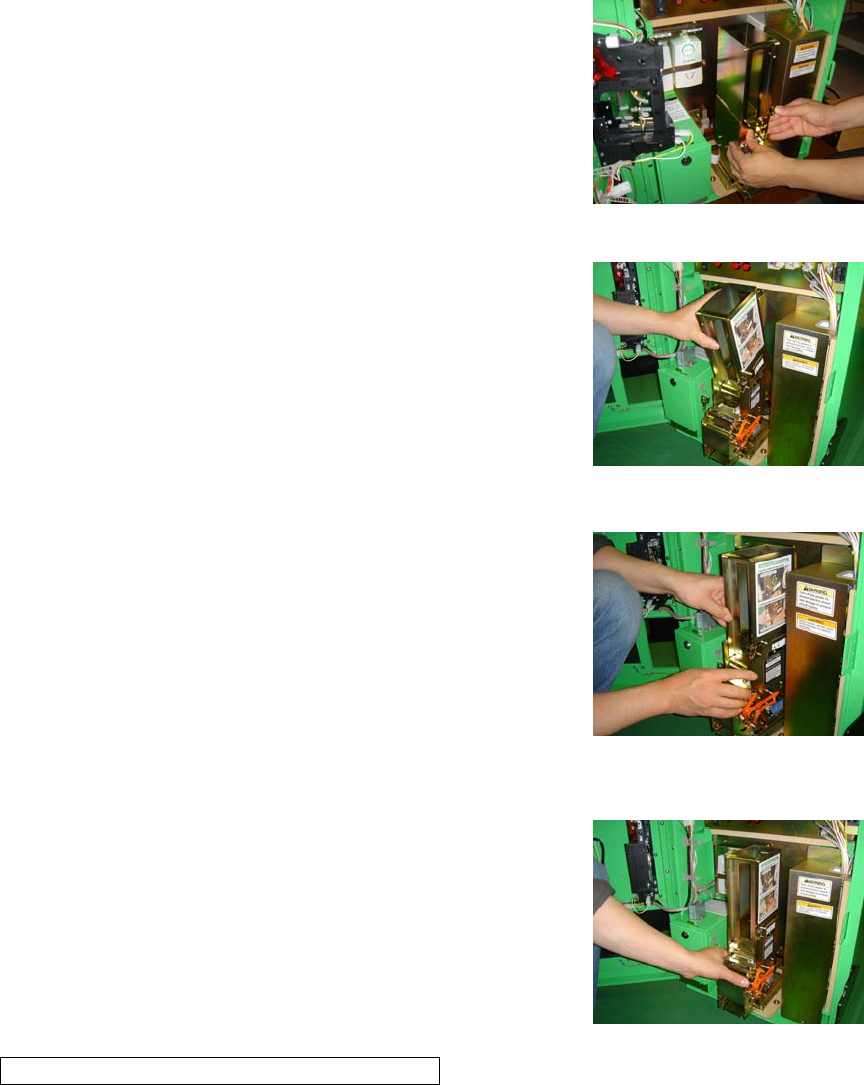
7-3 REFILLING CARDS
When the card stock runs out while the game is operating, a warning
screen will be displayed.
If this screen is displayed, be sure to promptly refill the cards.
PHOTO 7-2a Warning Screen when Out of Cards
HOW TO REFILL CARDS
1. Open the service door and turn off the power switch in the
maintenance switch section.
PHOTO 7-2b
1) POWER SWITCH
2) CARD DISPENSER
2. While pushing the lever, raise it to open up the dispenser.
FIG. 7-2a
1) LOCK LEVER
PHOTO 7-2c
PHOTO 7-2d
3. Take out the card weight. This part is covered in an
air-wrap bag at the time of shipping.
PHOTO 7-2e

「Mushiking#1-eng.doc」 最終印刷日時:2010/01/14 14:16:00
25/27
4. Take the wrapping off the new cards and gently riffle through them.
・Load the cards with the front faced down.
・Cards come in packs of 200.
PHOTO 7-2f
5. Refill the cards. Do not load more than 600 cards.
6. Reposition the weight and close the refill door.
7. Turn the power back on and close the service door.
PHOTO 7-2g
(P. 22)
7-4 DEALING WITH JAMMED CARDS
If a card jam occurs while the game is operating, a warning screen
will be displayed. If this screen is displayed, be sure to remove the
jammed card immediately.
PHOTO 7-3a Jammed Card Warning Screen
HOW TO REMOVE A JAMMED CARD
1. Open the service door and turn off the power switch in the maintenance switch section .
2. Hold down the lock lever on the bottom section of the card dispenser
and pull out the card dispenser.
FIG. 7-3a
1) CARTRIDGE
2) LOCK LEVER
3) CARD DISPENSER UNIT
PHOTO 7-3b
「Mushiking#1-eng.doc」 最終印刷日時:2010/01/14 14:16:00
26/27
3. Push firmly on the front bottom of the cartridge while holding down
the lock lever on the right. The cartridge will slide back and stop.
PHOTO 7-3c
4. Lift up and release the cartridge. In some cases the bottom-most card
will be stuck but proceed to lift up the cartridge. Afterwards, remove
the jammed card.
PHOTO 7-3d
5. Reposition the cartridge. Align the cartridge with the △ symbol by pushing firmly from above. Then pull
the cartridge forward with both hands as shown in the picture.
Reinstalling the cartridge improperly will result in card dispenser
malfunctions. Be sure to consult the diagram below and proceed
carefully.
1) Align the △ symbol with position 1, and push firmly from above.
2) Pull forward so that the △ symbol aligns with position 2.
PHOTO 7-3e
(P. 22)
6. Return the card dispenser to the back.
7. Turn the power back on and close the service door.
PHOTO 7-3f
CARTRIDGE REINSTALLATION WARNING
As shown in the diagram, be sure that the cartridge is not slanted off center and that the cartridge tabs are
locked securely into the card dispenser.
1) Side View
2) Top View
「Mushiking#1-eng.doc」 最終印刷日時:2010/01/14 14:16:00
27/27
3) Incorrect
4) Correct
(P. 25)
8. PRECAUTIONS WHEN MOVING THE MACHINE
[!] WARNING
● When moving the machine, be sure to pull out the plug from the power supply.
Moving the machine with the plug still inserted can cause the power cord to be
damaged, resulting in a fire and/or electric shock.
● When moving the machine on the floor, remove the hold brackets and retract
the adjusters, and ensure that the casters make contact with the floor. Pay
careful attention so that the casters do not run over power cords and earth wires.
Damaging the power cords can cause an electric shock and/or short circuit.
● When the casters are in contact with the floor, it is possible that the cabinet
can move under its own weight if placed on an uneven area. Please be careful.
● When lifting the cabinet, be sure to hold the handles and the bottom part.
Lifting the cabinet by holding other portions may damage parts and installation
portions due to the empty weight of the cabinet, and may cause personal injury.
[!] CAUTION
Do not push the monitor cover or molded parts. This may cause damage to the
components, and the pieces may in turn cause injury.
Do not apply pressure to the cabinet’s molded parts when moving the cabinet. There is a risk of breaking
components and/or causing personal injury. When moving, be sure to use the handles at the upper back end
of the cabinet.
FIG. 8
1) MONITOR COVER
2) HANDLES
3) Do not apply pressure to the monitor cover or other molded parts.

「Mushiking#2-eng.doc」 最終印刷日時:2010/01/14 14:18:00
1/17
“MUSHIKING” (Owner’s Manual – 2/3) = 2004/05/19
(P. 27)
9. GAME DESCRIPTION
The following explanations apply only if the product is functioning correctly. If anything differs from
below, then a problem may have occurred. Immediately look into the cause
of the problem and fix it to ensure proper operation.
To draw maximum attention during standby mode, the monitor constantly
displays the advertisement (waiting-for-players) screen.
This screen, which includes the Mushiking story and game instructions
(with sound and BGM), loops repeatedly until coins are inserted. The option
of whether or not to play sound during the advertisement screen can be
configured in Test Mode settings.
PHOTO 9a
1) Advertisement screen display
2) Advertisement screen sound
GAME OUTLINE
・A Mushiking Card is dispensed at the beginning of play. When the player scans a Mushiking Card (using
the Card Reader), that beetle appears in the game.
・Mushiking Cards are comprised of two types, “Beetle Cards” and “Skill Cards”. One “Beetle Card” and
up to three “Skill Cards” can be scanned per play. Furthermore, the strength of the beetle will vary
depending on the combination of the two card types.
・Both available game types, single-player mode (“One player game”) and two-player versus mode (“Play
against a friend”), involve battling against another beetle,
where the first beetle to eliminate all of the opponent’s
health is the winner.
・During the countdown to battle, a rock-scissors-paper
game determines who will attack.
・The rock (“HIT”), scissors (“PINCH”), and paper
(“THROW”), attacks have varying attack power among the
different beetles, thus giving an element of strategic
planning to the rock-scissors-paper game.
HOW TO PLAY: Game Controls
(1) Insert coins.
(2) A Mushiking Card is dispensed.(※)
(3) The game starts on-screen.
1
2
「Mushiking#2-eng.doc」 最終印刷日時:2010/01/14 14:18:00
2/17
(4) Scan Mushiking Cards.
(5) Play a rock-scissors-paper game using the Skill Buttons.
※Note: Mushiking Cards are dispensed randomly. The player cannot
choose between Beetle Cards and Skill Cards.
PHOTO 9b
(P. 28)
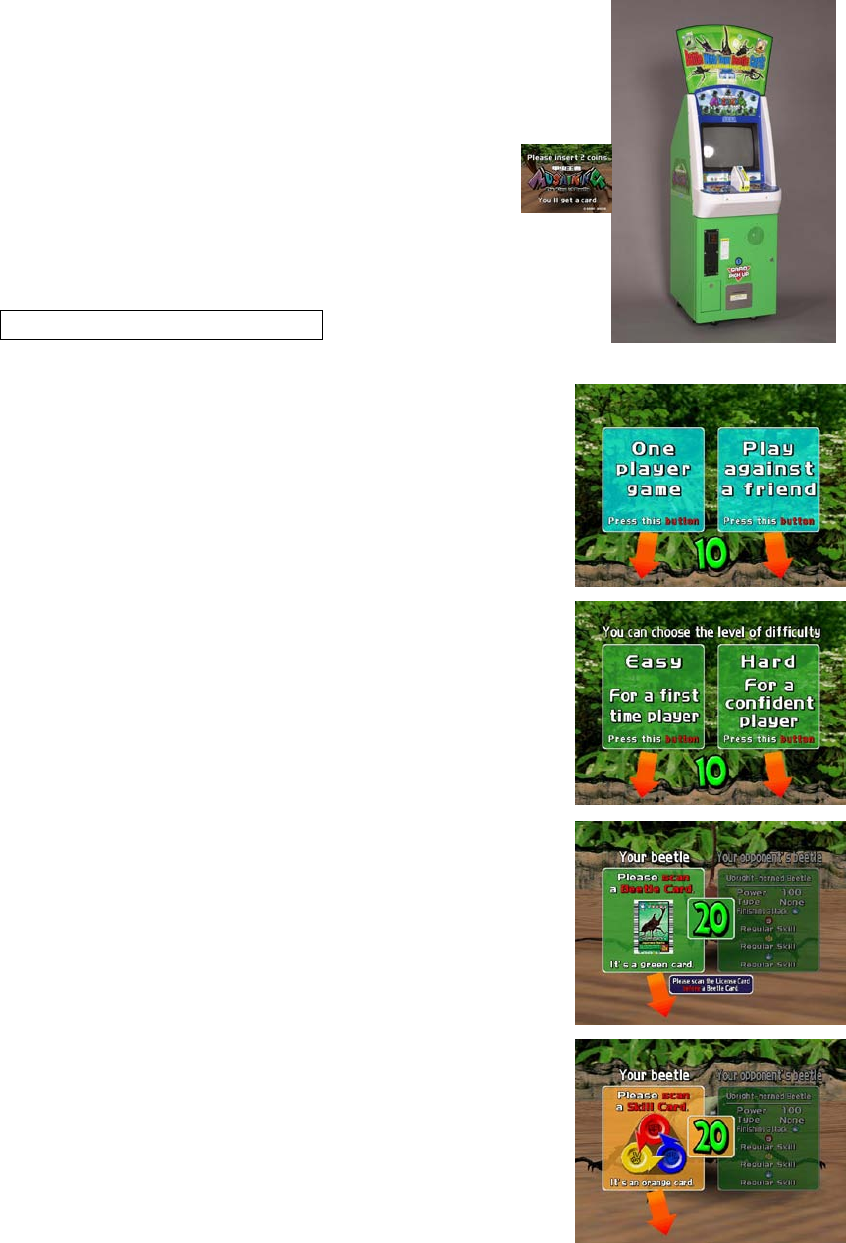
HOW TO PLAY: Screen Flow
(1) Insert coins to dispense cards.
(2) Taking the cards starts the game. Use the corresponding input
button to choose either a single-player or a two-player versus game.
(Screen 1)
Screen 1
(3) Choosing single-player lets the player choose a difficulty level.
Use the corresponding input button to choose “Easy” or “Hard”.
(Screen 2)
Screen 2
(4) The screen prompts players to scan a “Beetle Card” (using the
Card Reader), allowing them to scan the desired beetle. (Screen 3)
Note: If a “Beetle Card” is not scanned, a substitute beetle will
appear in battle and the game will proceed.
Screen 3
(5) The screen prompts players to scan “Skill Cards”, allowing them
to scan desired techniques. (Screen 4)
Note: The game will proceed even if “Skill Cards” are not scanned.
Screen 4

「Mushiking#2-eng.doc」 最終印刷日時:2010/01/14 14:18:00
3/17
(6) After completing all card scanning, the degree to which the beetle
has been powered up (enhanced attack power) by the applied card
combination is displayed. (Screen 5)
Screen 5
(7) Before starting the battle, players choose whether or not to receive
game instructions. (Screen 6)
Screen 6
(8) The battle begins. The player duels with the opponent’s beetle in a
rock-scissors-paper game by pressing a hand-gesture input button (rock,
paper, or scissors) within the battle countdown. (Screen 7)
Note: In single-player mode, a helper character (forest fairy) appears
with hints to help the player win.
Screen 7
(9) The winner of the rock-scissors-paper game attacks the opponent
with the chosen attack technique. The movement and attack power vary
depending on the attack technique. (Screen 8)
Winning with Rock → Attack with a HIT technique.
Winning with Scissors → Attack with a PINCH technique.
Winning with Paper → Attack with a THROW technique.
Screen 8
(10) The attacked beetle will lose health. After repeatedly exchanging
attacks, the first beetle to eliminate all of its opponent’s health is the
winner. (Screen 9)
Screen 9
「Mushiking#2-eng.doc」 最終印刷日時:2010/01/14 14:18:00
4/17
(11) Game Over
・In single-player mode, players can clear the game if they defeat the four opponent beetles from levels 1
to 4. On the other hand, if they are defeated by an opponent beetle during the course of play, this will result
in “Game Over”. There is no option to “Continue”. (Screen 10)
Screen 10
・In two-player mode, each player is granted entry of two beetles, and
the winner is the player with the last remaining beetle. (Screen 11)
Screen 11
HOW TO USE MUSHIKING CARDS
・There are two types of Mushiking Cards dispensed, “Beetle Cards” and “Skill
Cards”.
・Using “Beetle Cards” allows use of the card’s beetle in battle.
・Using “Skill Cards” allows the beetle to learn the card’s technique and
increase the beetle’s attack power.
・One of each type of “Skill Card”—Hit, Pinch, and Throw—can be used at the
same time for a total of three cards.
・The amount of increased attack power granted to the beetle depends on the
combination (compatibility) of “Beetle Cards” and “Skill Cards”.
・The greater the “Technique” value of a “Beetle Card”, the more likely it is for
the beetle to perform techniques with a high degree of difficulty. (They are
difficult, but they wield tremendous attack power.)
1) Beetle Card
2) Skill Card
「Mushiking#2-eng.doc」 最終印刷日時:2010/01/14 14:18:00
5/17
(P. 32)
10. EXPLANATION OF TEST AND DATA DISPLAY
By operating the TEST and SERVICE Buttons on the maintenance switch unit, periodically perform tests
and data check. When installing the machine for the first time, collecting cash, or when the machine does
not function correctly, perform a machine check in accordance with the explanations given in this section.
The following shows tests and modes that should be utilized as applicable.
This product's basic system consists of the NAOMI game board. The system enables you to play several
games one after the other just by changing a ROM board case that is to be set on the NAOMI case.
The product, therefore, supports the following 2 test modes:
(1) System test mode for an automatic self-diagnostic test (generally used by every product that contains
the basic system) and for a coin assignment (specifically used by this product) and
(2) Game test mode for testing the input/output control devices and setting the difficulty level (specifically
used by this product).
This manual does not cover the automatic self-diagnostic test. For more information about the system test
mode, see the attached NAOMI Service Manual.
TABLE 10 EXPLANATION OF TEST MODE
------------------------------------------------------------------------------------------------------------------------
ITEMS DESCRIPTION REFERENCE SECTIONS
------------------------------------------------------------------------------------------------------------------------
INSTALLATION OF MACHINE
When the machine is installed, perform the following:
1. Check to ensure each setting is the standard setting at shipment. S/M* & 10-2
2. Check each Input equipment in the INPUT TEST mode. 10-3 (2), (4)
3. Check each Output equipment in the CARD DISPENSER TEST mode. 10-3 (5)
4. Test on-IC-Board IC's in the self-test mode. S/M*
------------------------------------------------------------------------------------------------------------------------
MEMORY TEST
This test is automatically executed by selecting RAM TEST or ROM BOARD TEST in the Menu mode.
S/M*
------------------------------------------------------------------------------------------------------------------------
PERIODIC SERVICING
Periodically perform the following:
1. Run Memory Test. S/M*& 10-2
2. Ascertain each setting. —
3. Test each Input equipment in the INPUT TEST mode. 10-3 (2), (4)
4. Test each Output equipment in the CARD DISPENSER TEST mode. 10-3 (5)
------------------------------------------------------------------------------------------------------------------------
CONTROL SYSTEM
1. Check each Input equipment in the INPUT TEST mode. S/M* & 10-3
2. Adjust or replace each Input equipment. 10-3 (2), (4), (5)
3. If the problem still persists, check each equipment's mechanism movements.

「Mushiking#2-eng.doc」 最終印刷日時:2010/01/14 14:18:00
6/17
Sections 11, 12, 14
------------------------------------------------------------------------------------------------------------------------
MONITOR (CRT)
In the Monitor Adjustment mode, check to see if Monitor adjustments are appropriate.
S/M* & Section 15
------------------------------------------------------------------------------------------------------------------------
IC BOARD
Memory Test. S/M*
------------------------------------------------------------------------------------------------------------------------
S/M*: NAOMI Service Manual
(P. 33)
10-1 MAINTENANCE SWITCH UNIT AND COIN METER
[!] WARNING
Never touch places other than those specified. Touching places not specified
can cause electric shock and short circuit accidents.
(STOP) IMPORTANT
● Adjust the sound to an optimal level, taking into consideration the
environmental requirements of the installation location.
● Removing the Coin Meter circuitry renders the game inoperable.
Maintenance Switch Unit
Open the service door, and the maintenance switch unit shown will appear.
The function of each switch is as follows:
(1) SOUND VOLUME (VOLUME): Sound volume can be adjusted for the speakers.
(2) POWER SWITCH (POWER): Switch ON/OFF the power supply.
(3) DEMAGNETIZER BUTTON (DEMAG):
Eliminates the on-screen color unevenness due to
magnetization of CRT. Use this switch first before performing
the monitor's color adjustment.
(4) TEST BUTTON (TEST): When operating TEST Button, refer to the following pages.
(5) SERVICE BUTTON (SERVICE): Gives credits without registering on the coin meter.

「Mushiking#2-eng.doc」 最終印刷日時:2010/01/14 14:18:00
7/17
FIG. 10a
1) Power switch off.
2) SPEAKER VOLUME
3) POWER SWITCH
4) DEMAGNETIZER BUTTON
5) TEST BUTTON
6) SERVICE BUTTON
Coin Meter
The Coin Meter counts the number of coins inserted into the coin slot.
Open the Cashbox Door by using the key to have the Coin Meter appear underneath the Cashbox.
FIG. 10b
1) CASH BOX
FIG. 10c
1) COIN METER
(P. 34)
10-2 SYSTEM TEST MODE
(STOP) IMPORTANT
● The settings changed in Test Mode are stored when Test Mode is ended using
EXIT in the menu mode. If the power is turned off before Test Mode is finished, the
setting changes do not take effect.
● Executing BACKUP DATA CLEAR in System Test Mode does not clear the
bookkeeping data in Game Test Mode.
● Entering Test Mode clears fractional number of coins less than one credit and
bonus added data.
System Test Mode can be used to check IC Board functioning, adjust the monitor, and change coin settings.
Refer to the NAOMI Service Manual for details. However, be sure to employ the settings outlined below
for this product.
●CABINET TYPE: 1 PLAYER (S)
●MONITOR TYPE: HORIZONTAL
●COIN CHUTE TYPE: COMMON

「Mushiking#2-eng.doc」 最終印刷日時:2010/01/14 14:18:00
8/17
(P. 35)
10-3 GAME TEST MODE
(1) GAME TEST MENU
SYSTEM TEST MENU Screen
GAME TEST MENU Screen
Select GAME TEST MODE from the System Test Menu screen to
display the Game Test Menu screen as follows.
Use the SERVICE Button to move the cursor to the desired test
item. Press the TEST Button to enter the selected item.
After selecting an item, read the explanations below [(2) ~ (8)]
regarding operation.
After making changes, be sure to select EXIT and press the TEST Button in order to enable the new
settings.
Select EXIT and press the TEST Button to end the Game Test Mode and return to the System Test Menu
screen. Select EXIT and press the TEST Button again to end System Test Mode and return to the game
screen.
(2) INPUT TEST
Select INPUT TEST to display the following screen and check the status of input devices.
This test should be run periodically to ensure that each input device is functioning correctly.
INPUT TEST Screen
The input buttons are functioning correctly if each respective display changes from “OFF” to “ON” when
pressing the input buttons.
Press the SERVICE and TEST Buttons simultaneously to return to the Game Test Menu screen.

「Mushiking#2-eng.doc」 最終印刷日時:2010/01/14 14:18:00
9/17
(P. 36)
(3) CRT TEST
Select CRT TEST to display the following screen and check the status of the CRT (monitor).
This test should be run periodically to check the monitor condition.
CRT TEST Screen <1/3>
CRT TEST Screen <2/3>
CRT TEST Screen <3/3>
Pressing the TEST Button will display the “Color Bar”, “All Black”, and “All White” screens in order.
Press the TEST Button again to return to the Game Test Menu screen.
Refer to Section 15, “MONITOR”, for more information on CRT adjustment.
(4) BARCODE READER TEST
Select BARCODE READER TEST to display the following screen and check the status of the barcode
reader. This test should be run periodically to check the condition of the barcode reader.
1) READER TEST Screen
2) Screen showing a “Beetle Card” scan
3) Screen showing a “Skill Card” scan
Scan a “Beetle Card” and a “Skill Card”. If scanned correctly, a message will be displayed on the screen
under STATUS.
A failed scan, or scanning cards other than Beetle or Skill cards will result in “------“ to be displayed.
Move the cursor to EXIT and press the TEST Button to return to the Game Test Menu screen.
(5) CARD DISPENSER TEST

「Mushiking#2-eng.doc」 最終印刷日時:2010/01/14 14:18:00
10/17
Select CARD DISPENSER TEST to display the following screen and check the status of the card dispenser.
This test should be run periodically to check the condition of the card dispenser.
CARD DISPENSER TEST Screen
Move the cursor to CARD DISPENSER and press the TEST Button.
Different STATUS messages will be displayed depending on the operation status of the Card Dispenser.
“OK”: It is possible to dispense the card.
“CARD JAMMED”: A card is jammed.
“CARD EMPTY”: There are no cards in the dispenser.
“------”: There is either no Card Dispenser attached, the dispenser is in the middle of
dispensing, or something not listed above has occurred.
Move the cursor to EXIT and press the TEST Button to return to the Game Test Menu screen.
(6) MANAGEMENT CHIP STATUS
Select MANAGEMENT CHIP STATUS to display the following screen and check the status of the
management chips.
MANAGEMENT CHIP STATUS Screen
If the Management Chip is read correctly, “READ SUCCESS” will be displayed to the right of “CHIP *”.
<Other Possible Messages>

「Mushiking#2-eng.doc」 最終印刷日時:2010/01/14 14:18:00
11/17
“READER NOT READY”: There is no Card Reader interface board.
“NOW ACCESS”: In the middle of reading data.
“READ ERROR”: The read failed.
“UNKNOWN CHIP FORMAT”: The chip code, etc. is wrong.
THE REST: The number of times remaining on the Management Chip.
***/*** = Initial Number/Remaining Number
FIRST SET DATE: Displays the Management Chip’s initial date of installation.
Move the cursor to EXIT and press the TEST Button to return to the Game Test Menu screen.
(7) BOOKKEEPING
Select BOOKKEEPING to display the following operating data.
BOOKKEEPING MENU Screen
Use the SERVICE Button to move the cursor to the desired test item. Press the TEST Button to enter the
selected item. After selecting an item, read the explanations below [(A) ~ (E)] regarding operation.
Move the cursor to EXIT and press the TEST Button to return to the Game Test Menu screen.
(A) PLAY COUNT
Select PLAY COUNT to see the following screen and view the number of plays.
PLAY COUNT Screen
TOTAL COUNT: Total number of plays.

「Mushiking#2-eng.doc」 最終印刷日時:2010/01/14 14:18:00
12/17
1PLAY COUNT: Total number of single-player plays.
2PLAY COUNT: Total number of two-player plays.
1P EASY COUNT: Number of single-player EASY Mode plays.
1P HARD COUNT: Number of single-player HARD Mode plays.
TODAY 1PLAY: Number of single-player plays on the current day.
TODAY 2PLAY: Number of two-player plays on the current day.
1P EASY LEVEL CLEAR: Number of single-player EASY Mode game completions.
1P HARD LEVEL CLEAR: Number of single-player HARD Mode game completions.
Move the cursor to EXIT and press the TEST Button to return to the Bookkeeping Menu screen.
(p. 38)
(B) TIME HISTOGRAM
Select TIME HISTOGRAM to see the following screen and check the play count for any given day and
time.
TIME HISTOGRAM Screen
Select CONTINUE with the SERVICE Button and press the TEST Button to advance to the next screen.
One week of data [7 days (Pages)] are saved, constantly overwriting the oldest data first.
Move the cursor to EXIT and press the TEST Button to return to the Bookkeeping Menu screen.
「Mushiking#2-eng.doc」 最終印刷日時:2010/01/14 14:18:00
13/17
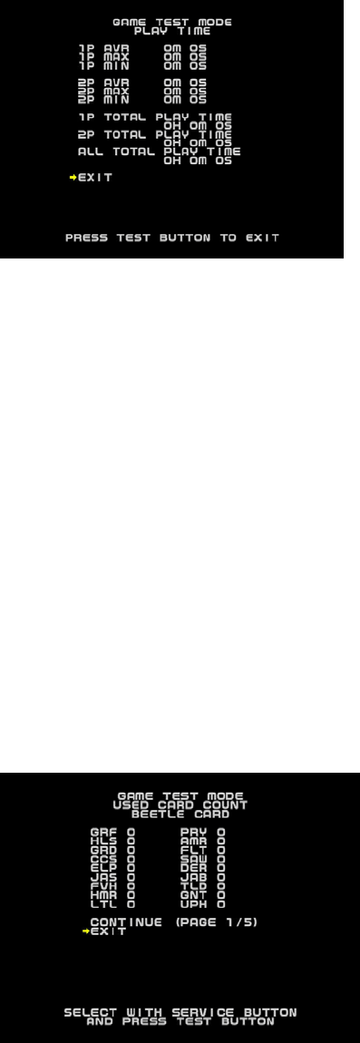
(C) PLAY TIME
Select PLAY TIME to see the following screen and view duration of play.
PLAY TIME Screen
1P AVR: Average single-player play time.
1P MAX: Longest single-player play time.
1P MIN: Shortest single-player play time.
2P AVR: Average two-player play time.
2P MAX: Longest two-player play time.
2P MIN: Shortest two-player play time.
1P TOTAL PLAY TIME: Total single-player play time.
2P TOTAL PLAY TIME: Total two-player play time.
ALL TOTAL PLAY TIME: Total combined play time.
Move the cursor to EXIT and press the TEST Button to return to the Bookkeeping Menu screen.
(D) USED CARD DATA
Select USED CARD DATA to see the following screen and view the number of times each card has been
scanned for use in the game.
USED CARD DATA Screen

「Mushiking#2-eng.doc」 最終印刷日時:2010/01/14 14:18:00
14/17
Select CONTINUE with the SERVICE Button and press the TEST Button to cycle through the pages (1/5,
2/5, …, 5/5 and back to 1/5).
Move the cursor to EXIT and press the TEST Button to return to the Bookkeeping Menu screen.
(p. 39)
Table showing names and cards used in USED CARD DATA.
Table 10-3a
--------------------------------------------------------------------------------------------------------
Name Beetle Card Japanese Name
--------------------------------------------------------------------------------------------------------
GRF Giraffe Stag-beetle ギラファノコギリクワガタ
HLS Hercules Beetle ヘルクレスオオカブト
GRD Grand Stag-beetle グランディスオオクワガタ
CCS Caucasus Beetle コーカサスオオカブト
ELP Elephant Beetle エレファスゾウカブト
JAS Japanese Stag-beetle オオクワガタ
FVH Five Horned Beetle ゴホンヅノカブト
HMR Humorous Stag-beetle メンガタクワガタ
LTL Little Stag-beetle コクワガタ
PRY Parry Stag-beetle セアカフタマタクワガタ
AMR Armor Stag-beetle ミヤマクワガタ
FLT Flat Stag-beetle ヒラタクワガタ
SAW Saw tooth Stag-beetle ノコギリクワガタ
DER Deer Stag-beetle
エレファスホソアカクワガ
タ
JAB Japanese Beetle カブトムシ
TLD Thailand Five Horned Beetle タイゴホンヅノカブト
GNT Grant White Beetle グラントシロカブト
UPH Upright-horned Beetle ノコギリタテヅノカブト
ACT Actaeon Beetle アクティオンゾウカブト
PWN Palawan Stag-beetle パラワンオオヒラクワガタ
RCR Rhinoceros Beetle メンガタカブト
SPS Specious Stag-beetle スペキオシスシカクワガタ
NEP Neptune Beetle ネプチューンオオカブト

「Mushiking#2-eng.doc」 最終印刷日時:2010/01/14 14:18:00
15/17
ATL Atlas Beetle アトラスオオカブト
FLH Flat Horned Beetle ヒルトゥスヘラヅノカブト
RUS Rusty Beetle サビイロカブト
YEL Yellow-winged Stag-beetle ラコダールツヤクワガタ
CHI Chilean Stag-beetle コガシラクワガタ
TRD Tarandus Stag-beetle タランドゥスツヤクワガタ
GLD Golden Stag-beetle オウゴンオニクワガタ
Table 10-3a
--------------------------------------------------------------------------------------------------------
Name Skill Card Japanese Name
--------------------------------------------------------------------------------------------------------
BANG Banging Smash ガンガンスマッシュ
DRGN Dragon Attack ドラゴンアタック
DANG Dangun ダンガン
SMSH Rolling Smash ローリングスマッシュ
BULL Bull Lock ブルロック
CRCH Rolling Clutch Hold
ローリングクラッチホール
ド
KING Kingfisher Hug カワセミハッグ
CUTR Running Cutter ランニングカッター
DRIV Rolling Driver ローリングドライバー
SSTH Sidescrew Throw サイドスクリュースロー
TRND Tornado Throw トルネードスロー
BOMB Sidelock Bomb サイドロックボム
DSHA Daisharin ダイシャリン
SLEP Crushing Sleeper Hold デビルスリーパー
MGUN Machine Gun Punches ヒャクレツケン
Table 10-3a
--------------------------------------------------------------------------------------------------------
Name Super Skill Card Japanese Name
--------------------------------------------------------------------------------------------------------

「Mushiking#2-eng.doc」 最終印刷日時:2010/01/14 14:18:00
16/17
Table 10-3a
--------------------------------------------------------------------------------------------------------
Name Special Skill Card Japanese Name
--------------------------------------------------------------------------------------------------------
FINS
H Finishing Attack Stopper 必殺ふうじ
LAST
PW Last Resort 最後の力
TIEB
RK The Tie Breaker あいこやぶり
CONF
U Confusion 必殺よこく
AGIT
A Agitation あせらせ
CHLI
NG Counter Attack Healing はんげきかいふく
HLIN
G Healing かいふく
(P. 41)
(E) CARD DISPENSER DATA
Select CARD DISPENSER DATA to see the following screen and view each Card Dispenser status
category.
CARD DISPENSER DATA Screen
DANG Super Dangun スーパーダンガン
SMSH Super Rolling Smash
スーパーローリングスマッシ
ュ
KING Super Kingfisher Hug スーパーカワセミハッグ
CUTR Super Running Cutter スーパーランニングカッター
TRND Super Tornado Throw スーパートルネードスロー
BOMB Super Sidelock Bomb スーパーサイドロックボム
DSHA Super Daisharin スーパーダイシャリン
「Mushiking#2-eng.doc」 最終印刷日時:2010/01/14 14:18:00
17/17
CARD PAY OUT COUNT: The number of cards dispensed.
CARD JAMMED COUNT: The number of jammed cards.
CARD EMPTY COUT: The number of “CARD EMPTY” occurrences.
The number of cards dispensed during Test Mode (Card Dispenser Test) is not included in the count.
Move the cursor to EXIT and press the TEST Button to return to the Bookkeeping Menu screen.
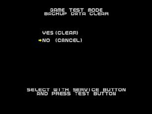
(8) BACKUP DATA CLEAR
Select BACKUP DATA CLEAR to clear the contents of BOOKKEEPING data in the Game Test Mode.
BACKUP DATA CLEAR Screen
To clear data, use the SERVICE Button to move the cursor to YES (CLEAR) and then press the TEST
Button.
During Data Clear, “COMPLETED” will be blinked to the right of YES. When Data Clear is complete, the
“COMPLETED” display will disappear.
Press the TEST Button again to return to the Game Test Menu screen.
Move the cursor to NO (CANCEL) and press the TEST Button to return to the Game Test Menu screen
without clearing the data.
「Mushiking#3-eng.doc」 最終印刷日時:2010/01/14 14:19:00
1/17
“MUSHIKING” (Owner’s Manual - 3/3) = 2004/05/18
(P. 42)
11. CARD DISPENSER
[!] WARNING
● When working with the machine, be sure to turn the power off. Working with
the power on can cause an electric shock or a short circuit.
● Be careful not to damage the wires. Damaged wires may cause electric
shock, short circuit, or present a risk of fire.
● Do not touch undesignated places. Touching these places can cause electric
shock or short circuit.
● This work should be performed by the site maintenance individual or another
skilled professional. Performing work by non-technical personnel can cause
severe accidents such as electric shock.
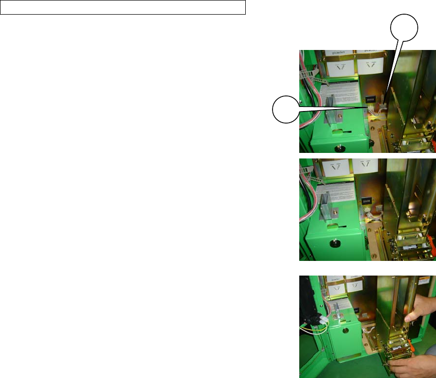
HOW TO REMOVE THE CARD DISPENSER
1. Turn off the main AC unit power switch and open the service door.
2. Unfasten the cord clamp and connecter on the cable connected to the
card dispenser, and pull the card dispenser forward while pushing down
on the lock lever on the lower section of the card dispenser.
PHOTO 11a
1) CORD CLAMP
2) CONNECTOR
PHOTO 11b
3. When it cannot be pulled forward any further, lift up on the card
dispenser and detach it from the rail.
PHOTO 11c
1
2
「Mushiking#3-eng.doc」 最終印刷日時:2010/01/14 14:19:00
2/17
(P. 43)
12. CARD READER (CONTROL PANEL)
[!] CAUTION
● When cleaning the card reader, always use the designated Cleaning Card.
● Do not use chemical detergents such as “glass cleaner” available on the
market or solvents such as thinner, etc.
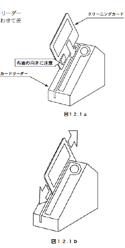
12-1 HOW TO CLEAN THE CARD READER
1. Insert the Cleaning Card, aligning the cloth side with the red light in
the Card Reader groove.
FIG. 12-1a
1) CLEANING CARD
2) CARD READER
3) Insert with the cloth side facing the correct direction.
2. Slowly slide the Cleaning Card up and down to clean off any accumulated dirt.
After cleaning, refer to "10-3 Game Test Mode, (4) Barcode Reader Test" to test
the functionality.
(P. 40)
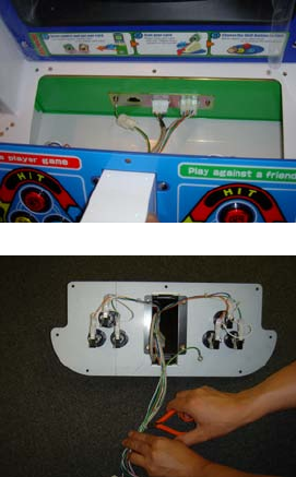
12-2 HOW TO REMOVE THE CARD READER
[!] WARNING
● When working with the machine, be sure to turn the power off. Working with
the power on can cause an electric shock or a short circuit.
● Be careful not to damage the wires. Damaged wires may cause electric
shock, short circuit, or present a risk of fire.
● Do not touch undesignated places. Touching these places can cause electric
shock or short circuit.
● This work should be performed by the site maintenance individual or another
skilled professional. Performing work by non-technical personnel can cause
severe accidents such as electric shock.
「Mushiking#3-eng.doc」 最終印刷日時:2010/01/14 14:19:00
3/17
1. Turn off the main AC unit power switch.
2. Remove the 8 truss screws on the control panel.
FIG. 12-2
1) TRUSS SCREW (8), chrome / M4×12
3. Being careful not to damage the cord, unplug the connector from the
control panel and pull it out of the cabinet.
PHOTO 12-2a
1) CONNECTOR
4. Remove the cord clamp and use nippers to cut the 2 tie belts loose.
PHOTO 12-2b
1) CORD CLAMP
2) Cut with nippers.
5. Unfasten the 4 carriage bolts and 4 flange nuts holding the card reader bracket in place and remove the
card reader from the control panel.
PHOTO 12-2c
1) CARD READER BRACKET
2) CARRIAGE BOLT (4), chrome / M4 x12
3) FLANGE NUT (4) / M4
6. Remove the card reader cover and detach the card reader from the card reader bracket.
1) CARD READER COVER
(P. 46)
13. POWER & I/O BOARD UNIT
[!] WARNING
● When working with the machine, be sure to turn the power off. Working with
the power on can cause an electric shock or a short circuit.
● Be careful not to damage the wires. Damaged wires may cause electric

「Mushiking#3-eng.doc」 最終印刷日時:2010/01/14 14:19:00
4/17
shock, short circuit, or present a risk of fire.
● Do not touch undesignated places. Touching these places can cause electric
shock or short circuit.
● This work should be performed by the site maintenance individual or another
skilled professional. Performing work by non-technical personnel can cause
severe accidents such as electric shock.
13-1 HOW TO REMOVE THE POWER & I/O BOARD UNIT
1. Turn off the main AC unit power switch.
2. Remove the 2 tamperproof screws and detach the back door.
PHOTO 13-1a
1) BACK DOOR
2) TAMPERPROOF SCREW (2), chrome / M4×8
3. Unplug all the connectors plugged into the Power & I/O Board unit.
PHOTO 13-1b
PHOTO 13-1c
1) Front 9 points
2) Rear 3 points
4. Remove the 2 wing bolts and pull out the board.
PHOTO 13-1d
1) SCREW (2) / M4 x 20, w/flat & spring washers + flat washer
(4.4 – 16 x 1.6)
(P. 47)
13-2 COMPOSITION OF THE POWER & I/O BOARD UNIT
PHOTO 13-2
1) MAINTENANCE SWITCH SECTION
2) SERIAL INTERFACE BOARD
1

「Mushiking#3-eng.doc」 最終印刷日時:2010/01/14 14:19:00
5/17
3) AUDIO POWER AMPLIFIER
4) POWER UNIT
5) I/O CONTROL BOARD
【要切抜き】
1
2
3
4
1

「Mushiking#3-eng.doc」 最終印刷日時:2010/01/14 14:19:00
6/17
(P. 48)
14. COIN SELECTOR
REMOVING THE COIN SELECTOR
Loosen the plastic-head screw to raise the lever and open the coin
selector cover and then remove the coin selector.
REMOVING A JAMMED COIN
When the coin return button fails to refund coins, open the coin
chute door and open the selector gate. Once the jammed coin is
removed, insert a standard coin to ensure that the selector is
working properly.
FIG. 14a
CLEANING THE COIN SELECTOR
(STOP) IMPORTANT
● Remove and clean smears using a soft cloth dipped in water or diluted
chemical detergent and then wrung dry.
● Never apply machine oil, etc. to the coin selector.
● After cleaning the coin selector, properly insert a standard coin to ensure that
the selector functions correctly.
The coin selector should be cleaned once every 3 months. When cleaning, follow the procedures below:
1. Turn off the main AC unit power switch and open the coin chute door.
2. Open the gate and remove dust using a soft brush (made of wool, etc.).
3. Remove and clean smears by using a soft cloth dipped in water or diluted chemical detergent and then
wrung dry.
4. Remove the cradle. When detaching the retaining ring (E ring), be extra careful not to bend the rotational
axis.
5. Use a soft cloth to wipe any dirt/debris off the rotational axis and bearings.
6. After wiping as described in the previous step, use a dry cloth, etc. to dry the coin selector completely.
COIN INSERTION TEST
Once every month, when performing the Coin Switch Test, check the following points:
□ Does the Coin Meter count properly?
□ Do coins drop into the Cashbox correctly?
□ Are coins rejected when inserted while holding down the Reject Button?
LEVER
COIN SELECTOR COVER
「Mushiking#3-eng.doc」 最終印刷日時:2010/01/14 14:19:00
7/17
FIG. 14b
FIG. 14c
1) GATE
2) CRADLE
(P. 49)
15. MONITOR
15-1 CAUTIONS/WARNINGS REGARDING SAFETY FOR
HANDLING THE MONITOR
Before handling the monitor, be sure to read the following points and comply with the caution/warning
instructions given below. Note the caution/warning symbols and letters used in the instructions.
[!] WARNING
Indicates that handling the monitors improperly by disregarding this warning may
potentially cause a hazardous situation, which could result in death or serious
injury.
[○]
Indicates that access to a specific part of the equipment is forbidden.
[!] CAUTION
Indicates that handling the monitors improperly by disregarding this warning may
potentially cause a hazardous situation, which could result in death or serious
injury.
[●]
Indicates the instruction to disconnect or unplug a power connector.
[!] WARNING
● When performing such work as installing and removing the monitor, inserting
and disconnecting the external connectors to and from the monitor interior and
the monitor itself, be sure to disconnect the power connector (plug) beforehand.
Proceeding without doing so can cause electric shock or malfunctioning.
「Mushiking#3-eng.doc」 最終印刷日時:2010/01/14 14:19:00
8/17
● Use of the monitor by converting it without permission is not allowed. SEGA
shall not be liable for any malfunctioning and accidents caused by such a
conversion.
[!] WARNING
● Primary side and Secondary side
The monitor's circuit, which is divided into the Primary side and Secondary side, is
electrically isolated. Do not touch the Primary side, or touch both the primary side and
the secondary side simultaneously. Failing to observe this instruction can cause electric
shock, leading to serious danger. When making monitor adjustments, use a non-
conductive driver and make them without touching any part other than the Adjustment V.
R. and knob. Also, be sure not to cause a short circuit to the Primary side and Secondary
side. If a short circuit occurs, it can cause electric shock or malfunctioning, which poses
a serious risk of danger.
1) SECONDARY SIDE (Chassis, CRT, etc.)
2) PRIMARY SIDE
● High Voltage
Some of the parts inside the monitor are subject to high voltage in excess of 20,000 volts
and pose a serious threat. Therefore, do not touch the monitor interior. Should soldering &
paper wastes, etc. be mixed in the monitor interior, turn the power off so as not to cause
malfunctioning or a fire hazard.
1) DEMAGNETIZER COIL
2) ANODE CAP
3) ANODE LEAD Approx. 29 kV
4) FOCUS LEAD (black) Approx. 10 kV
5) PRIMARY SIDE
6) MAIN BOARD
7) FBT Approx. 29 kV
8) SECONDARY SIDE (Chassis, Metal Plate, CRT, etc.)
9) Disconnect or unplug.
10) REAR PART
11) DEMAGNETIZER COIL
12) NECK PCB
13) Approx. 10 kV
● Connecting the CRT and PCB
When combining the CRT and PCB, use the specified part No. to maintain the
「Mushiking#3-eng.doc」 最終印刷日時:2010/01/14 14:19:00
9/17
factory settings. The anode of the CRT itself will charge as time elapses,
generating high voltage that is very dangerous. The monitor should be used with
the Chassis, CRT, and PCB assembled. When repair, etc. is required at the time of
malfunctioning, be sure to send it in an assembled state. If it is disassembled, the
charged high voltage can be released, causing a very hazardous situation.
Therefore, under no circumstances should it be disassembled.
[!] CAUTION
● Static Electricity
Touching the CRT surface sometimes causes a slight shock. This is because the
CRT surfaces are subject to static and will not adversely affect the human body.
● Installation and Removal
Ensure that the Demagnetizer Coil, FBT (Fly-Back Transformer), Anode Lead, and
Focus Lead are not positioned close to the sheet metal work's sharp edges, etc.
and avoid damaging the insulated portions so as not to cause electric shock
and malfunctioning. (For the name of parts, refer to the figures above.)
(P. 46)
15-2 CLEANING THE CRT SURFACES AND THE MONITOR
COVER
[!] CAUTION
Observe the following points to prevent damage when cleaning accessory
surfaces.
● Remove smears using a dry, soft cloth (flannel, etc.). Do not use coarse gauze
or other harsh materials.
● For smear removing solvent, alcohol (ethanol) is recommended. When using
chemical detergent, be sure to follow the instructions below:
● Soak a soft cloth in a neutral household detergent diluted with water. Wring
the cloth well, and then clean down the surface.
● Do not use bleach or detergent that contains abrasive agents.
● Do not use alkaline chemical detergents such as “glass cleaner” available on
the market or solvents such as thinner, etc.
● Do not scrape or scratch surfaces using brushes, scouring pads, or other hard
cleaning utensils.

「Mushiking#3-eng.doc」 最終印刷日時:2010/01/14 14:19:00
10/17
Clean the CRT surface and the monitor cover once a week. Apply antistat after cleaning.
1. Turn off the main AC unit power switch.
2. Remove the 7 truss screws and detach the monitor cover.
3. The monitor (CRT) will be exposed. Use an untreated soft cloth to wipe off both the CRT surface and the
monitor cover.
4. After cleaning, spray antistat onto the CRT and the monitor side of the monitor cover.
FIG. 15-2
1) TRUSS SCREW (3), chrome / M4 x 14; (reverse side of monitor cover) M4 NUT/WASHER STOPPER
2) TRUSS SCREW (4), chrome / M4 x 12
3) MONITOR COVER
(P. 52)
15-3 MONITOR ADJUSTMENT
[!] WARNING
● Monitor adjustments have been made at the time of shipment. Therefore, do
not make further adjustments without a justifiable reason. Adjusting the monitor
containing high-tension parts is dangerous. Also, an improper adjustment can
cause deviated synchronization and image fault, resulting in malfunctioning.
● When making monitor adjustments, use a resin regulating rod. Using bare
hands or conductive tools can cause electrocution.
● Be sure to perform appropriate adjustments of the monitor. When operating
this machine, do not leave the monitor's flickering or deviation unchecked.
Failure to observe this can worsen the players' or the customers' physical
conditions.
● Do not touch undesignated places. They can cause electric shock or short
circuit.
The monitor regulation board is located on the lower part of the monitor.
DESCRIPTION OF ADJUSTMENT KNOBS
FIG. 15-3a

「Mushiking#3-eng.doc」 最終印刷日時:2010/01/14 14:19:00
11/17
(1) R. GAIN: Adjusts each VR to get a suitable contrast and white balance.
(2) G. GAIN:
(3) B. GAIN:
(4) BRIGHT: Adjusts screen brightness.
(5) H POSI: Adjusts horizontal positioning of screen.
(6) H SIZE: Adjusts horizontal screen dimension.
(7) H HOLD: Adjusts horizontal scrolling of screen.
(8) V POSI: Adjusts vertical positioning of screen.
(9) V SIZE: Adjusts vertical screen dimension.
(10) V HOLD: Adjusts vertical scrolling of screen.
(P. 48)
HOW TO CONFIRM ADJUSMENTS
1. Enter TEST MODE and select GAME TEST MODE by positioning the cursor and pressing the TEST
Button.
2. Position the cursor with CRT TEST and press the TEST Button to display the CRT TEST screen.
FIG. 15-3b SYSTEM TEST MODE Screen
PHOTO 15-3a GAME TEST MENU Screen
PHOTO 15-3b CRT TEST Screen
1) The white frame is visible all around the screen.
2) The black portion of the image is not entirely visible around the
screen.
3) The 31st color gradation is set to be faintly visible. (The 32nd
4) The top 2 gradations are set at the same level. (No gradation
difference.)
gradation for each color is black.)

「Mushiking#3-eng.doc」 最終印刷日時:2010/01/14 14:19:00
12/17
(P. 54)
16. PERIODIC INSPECTION
The items listed below require periodic check and maintenance to retain the performance of this machine
and to ensure safe business operation.
[!] WARNING
● Be sure to check once a year to see whether Power Cords are damaged, the
plug is securely inserted, dust has accumulated between the Socket Outlet and
the Power Plug, etc. Using the product with accumulated dust can cause fire and
electric shock.
● Never use a water jet, etc. to clean inside and outside the cabinet. If the
machine gets wet for any reason, do not use it until it has completely dried.
● Periodically, around once a year, get in touch with the place of contact
herein stated or the Distributor, etc. where the product was purchased from,
regarding internal cleaning. Using the product with accumulated dust in the
interior can cause a fire or accident. Note that professional interior cleaning will
require a fee.
TABLE 16 PERIODIC INSPECTION TABLE
ITEMS DESCRIPTION PERIOD REFERENCE
CABINET Checking Adjusters/Hold Brackets grounding
Daily - before opening hours 3
MONITOR Screen Cleaning Biweekly 15
Check adjustments. Monthly 15
GAME BOARD Check settings. Monthly 10
CARD READER Head Cleaning Monthly 12
SPEAKERS/SOUND Sound Test, Check sound volume adjustment.
Monthly 10
COIN SELECTOR Coin Insertion Test Monthly 14
Cleaning Tri-monthly 14
POWER SUPPLY PLUG Inspection and Cleaning Annually See above.
INTERIOR Cleaning Annually See above.
CABINET SURFACES Cleaning As necessary Next Page
CLEANING THE CABINET SURFACES
「Mushiking#3-eng.doc」 最終印刷日時:2010/01/14 14:19:00
13/17
When the cabinet surfaces become dirty, remove stains with a soft cloth soaked in water or diluted (with
water) chemical detergent and then wrung dry. To avoid damaging the finish, do not use such solvents as
thinner, benzene, etc. (other than ethyl alcohol) or abrasives (bleaching agent and chemical dust-cloth).
Some general-purpose household, kitchen, and furniture cleaning products may contain strong solvents that
degrade plastic components, coatings, and print. Before using any cleaning product, read the product's
cautionary notes carefully and test the product first on a small area that is not highly visible.
(P. 55)
17. TROUBLESHOOTING
[!] WARNING
● In order to prevent electric shock and short circuit, be sure to turn power off
before working on the machine.
● Be careful not to damage wiring. Damaged wiring may cause electric shock
or short circuit.
● After fixing the problems regarding the Circuit Protector, reinstate the Circuit
Protector. Depending on the cause of the problem, using the Circuit Protector
without addressing the malfunction can generate heat and can present a fire
hazard.
● In the event that a problem cannot be resolved by employing the procedures
listed in this manual, be sure to request service from the office shown on this
manual or the dealer from whom the product was originally purchased. Attempts
to employ procedures other than those specified in this manual can cause
electrical shock, shorting, or fire.
(STOP) IMPORTANT
If a problem occurs, first check to make sure that the wiring connectors are
properly connected.
TABLE 17a TROUBLESHOOTING TABLE
PROBLEMS CAUSE COUNTERMEASURES
-------------------------------------------------------------------------------------------------------------------
Turning on the power switch fails to power on the machine.
--------------------------------------------------------------------------------------------------------
The power is not ON. Firmly insert the power plug into the outlet.
--------------------------------------------------------------------------------------------------------
Either the main switch or the power switch is turned off.
Turn on both the main switch and the power switch.
「Mushiking#3-eng.doc」 最終印刷日時:2010/01/14 14:19:00
14/17
--------------------------------------------------------------------------------------------------------
Incorrect power source/voltage. Make sure that the power supply/voltage is correct.
--------------------------------------------------------------------------------------------------------
The Circuit Protector malfunctions due to a power surge.
After eliminating the cause of the power surge, restore the
Circuit Protector of the AC Unit. (See next page.)
-------------------------------------------------------------------------------------------------------------------
Sound is not emitted.
--------------------------------------------------------------------------------------------------------
Sound volume adjustment is not correct.
Adjust the switch unit’s sound adjustment volume control.
--------------------------------------------------------------------------------------------------------
Sound-related circuit malfunction.
Perform SOUND TEST.
-------------------------------------------------------------------------------------------------------------------
Cards are not dispensed.
--------------------------------------------------------------------------------------------------------
Cards are empty. Refill cards.
--------------------------------------------------------------------------------------------------------
Card jam. Remove the jammed card(s).
--------------------------------------------------------------------------------------------------------
The connector is not connected properly.
Ensure proper connection.
--------------------------------------------------------------------------------------------------------
Card dispenser malfunction. Exchange the card dispenser.
-------------------------------------------------------------------------------------------------------------------
Cannot scan (read) cards.
--------------------------------------------------------------------------------------------------------
Card reader card slot is dirty. Use the attached cleaning card to clean the card slot.
--------------------------------------------------------------------------------------------------------
The connector is not connected properly.
Ensure proper connection.
--------------------------------------------------------------------------------------------------------
Card reader malfunction. Exchange the card reader.
-------------------------------------------------------------------------------------------------------------------
Cannot enter TEST MODE.
--------------------------------------------------------------------------------------------------------
Switch malfunction. Exchange the switch.
--------------------------------------------------------------------------------------------------------
Game Board abnormality. Exchange the Game Board.
--------------------------------------------------------------------------------------------------------
The operation used to change to TEST MODE is incorrect.
Ensure correct operation.
-------------------------------------------------------------------------------------------------------------------
Monitor display is abnormal.
--------------------------------------------------------------------------------------------------------
Game Board and monitor connection failure.
Ensure proper connection (of connector).
--------------------------------------------------------------------------------------------------------
Monitor malfunction. Exchange the monitor.
--------------------------------------------------------------------------------------------------------
Game Board malfunction. Exchange the Game Board.
-------------------------------------------------------------------------------------------------------------------
There is no response from control panel buttons.
--------------------------------------------------------------------------------------------------------
Button failure. Exchange the button(s).

「Mushiking#3-eng.doc」 最終印刷日時:2010/01/14 14:19:00
15/17
--------------------------------------------------------------------------------------------------------
The connector is not connected properly.
Ensure proper connection.
--------------------------------------------------------------------------------------------------------
Not set to game mode. Change setting to game mode.
-------------------------------------------------------------------------------------------------------------------
CIRCUIT PROTECTOR
The Circuit Protector uses a bimetal to break the circuit. Due to the heat, the machine cannot be restarted
until it cools. Wait at least 1 minute before restarting. (Press the button in.)
1) CIRCUIT PROTECTOR
(P. 57)
18. GAME BOARD
[!] WARNING
● In order to prevent electric shock and short circuit, be sure to turn power off
before working on the machine.
● Be careful not to damage wiring. Damaged wiring may cause electric shock
or short circuit.
● Do not expose the Game Board, etc. for no reason. Failure to observe this can
cause electric shock or malfunctioning.
[!] CAUTION
● There is no need to handle the Game Board for this machine since all setting
changes are done in TEST MODE. Failure to use the Game Board or any other IC
board as shipped can cause electric shock or malfunctioning.
● The chip components on IC boards can be damaged by electrostatic
discharge from the human body. Before handling an IC board, always neutralize
any static charge in the body by touching a grounded metal surface.
18-1 REMOVING THE GAME BOARD
This machine uses the NAOMI Board. When submitting for exchange or repair, remove the ASSY MAIN
BOARD from the cabinet and detach the NAOMI board according to the following procedures.
1. Turn off the main AC unit power switch and open the service door.
1
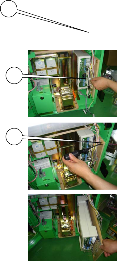
「Mushiking#3-eng.doc」 最終印刷日時:2010/01/14 14:19:00
16/17
2. Loosen the 2 truss screws and detach the NAOMI cover.
PHOTO 18-1a
1) NAOMI COVER
2) TRUSS SCREW (2), chrome / M4×8
3. Unplug all the connectors joined to the NAOMI board.
PHOTO 18-1b
1) CONNECTOR (total 9)
4. Remove the 1 wing bolt and pull out the ASSY MAIN BD.
PHOTO 18-1c
1) SCREW (2) / M4 x 20, w/flat & spring washers + flat washer (4.4
– 16 x 1.6)
PHOTO 18-1d
5. Remove the 4 screws and detach the NAOMI board from the base.
FIG. 18-1
1) SCREW (4) / M4×12, w/flat & spring washers
When submitting for exchange or repair, wrap the NAOMI Board (with the ROM Board still mounted) in
packing materials and submit in a carton box. (See Section 5.)
(P. 59)
2
1
1

「Mushiking#3-eng.doc」 最終印刷日時:2010/01/14 14:19:00
17/17
18-2 COMPOSITION OF THE GAME BOARD
(STOP) IMPORTANT
Use the Filter Board DIP SW only with the advised settings. Use with different
settings may cause the screen to display improperly or other malfunctions.
ASSY CASE NAO MKG 2K3 2ND USA (840-0150D-01): USA
ASSY CASE NAO MKG 2K3 2ND EXP (840-0150D-02): OTHERS
ASSY CASE NAO MKG 2K3 2ND KOR (840-0150D-03): KOREA
ASSY CASE NAO MKG 2K3 2ND AUS (840-0150D-04): AUSTRALIA
FIG. 18-2a
1) TRUSS SCREW (4), chrome / M3 x 30
2) ROM CASE NAO MKG 2K3 2ND
3) DIP SW
ENG / 840-0150C
4)
ASSY CASE NAO CRX MAIN SER USA (840-0002A-11): USA
ASSY CASE NAO CRX MAIN SER EXP (840-0002A-12): OTHERS
ASSY CASE NAO CRX MAIN SER KOR (840-0002A-13): KOREA
ASSY CASE NAO CRX MAIN SER AUS (840-0002A-14): AUSTRALIA
DIP SW Setting
Use this product with the DIP SW settings shown in the figure below.
FIG. 18-2b
(P. 60)
19. DESIGN-RELATED PARTS
For the Warning Display Stickers, refer to Section 1.
