Arcade Outrun 2 Sp Twin Manual OUTRUN2_TWIN UK REV_0 User
420-6796-02UK-OutRun2 420-6796-02UK-OutRun2
2013-11-21
User Manual: Arcade Outrun 2 Sp Twin Manual
Open the PDF directly: View PDF ![]() .
.
Page Count: 142 [warning: Documents this large are best viewed by clicking the View PDF Link!]

420-6796-02UK REV 0
SERVICE MANUAL
TWIN TYPE
Before using this product, read this SERVICE MANUAL carefully to understand the contents stated herein.
After reading this manual, be sure to keep it available nearby the product or somewhere convenient in order to
be able to refer to it whenever necessary.
Manufactured in the UK by
2
CONTENTS
1. BEFORE USING THIS PRODUCT..................................................................................................5
1.1. Inspections Immediately After Transporting The Product To The Location .......................................6
2. INTRODUCTION TO THIS SERVICE MANUAL ................................................................................8
3. INSTALLATION AND SERVICE INSTRUCTIONS .............................................................................9
3.1. Handling and Installation Precautions..........................................................................................9
3.2. Coin Handling ......................................................................................................................... 11
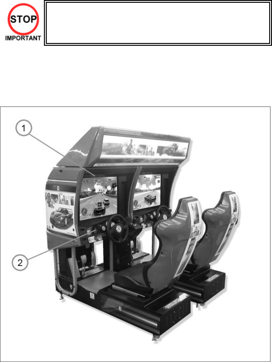
3.3. Name of Parts......................................................................................................................... 12
3.4. Accessories ........................................................................................................................... 13
3.5. Shipping the Game Board........................................................................................................ 14
3.6. Shipping the GD-ROM Drive ..................................................................................................... 16
3.7. Assembly Instructions ............................................................................................................. 17
3.7.1. Applying the Play Instructions ........................................................................................... 18
3.7.2. Assembling the Cockpit .................................................................................................... 19
3.7.3. Securing In Place (Leg Adjuster Adjustment) ...................................................................... 20
3.7.4. Billboard Installation.......................................................................................................... 22
3.7.5. Installing The AC Covers (Wire Covers ).............................................................................. 23
3.7.6. Coin Handling Installation .................................................................................................. 24
3.7.6.1. Wiring Connections.................................................................................................... 25
3.7.7. Communication Cables ..................................................................................................... 26
3.7.8. Connection To The Power Supply....................................................................................... 27
3.7.9. Assembly Check.............................................................................................................. 29
3.7.9.1. CRT Test .................................................................................................................. 29
3.7.9.2. Memory Test............................................................................................................. 30
3.7.9.3. Input Test.................................................................................................................. 31
3.7.9.4. Output Test ............................................................................................................... 32
3.7.9.5. Sound Test ............................................................................................................... 32
3.7.10. Moving The Machine...................................................................................................... 33
3.8. Fuses .................................................................................................................................... 34
3.9. Maintenance........................................................................................................................... 35
3.9.1. Handle Mecha.................................................................................................................. 36
3.9.1.1. Removing the Handle Mecha....................................................................................... 36
3.9.1.2. Replacing and Adjusting The Handle Mecha’s V.R. ....................................................... 36
3.9.1.3. Adjusting the VR....................................................................................................... 37
3.9.1.4. Replacing the VR....................................................................................................... 37
3.9.1.5. Greasing ................................................................................................................... 38
3.9.2. Accelerator & Brake......................................................................................................... 39
3.9.2.1. Removing the Accelerator & Brake.............................................................................. 39
3.9.2.2. Adjusting the V.R. ..................................................................................................... 40
3.9.2.3. Replacing the V.R...................................................................................................... 41
3.9.2.4. Greasing ................................................................................................................... 41
3.10. Shift Lever ........................................................................................................................... 42
3.11. Replacement of Fluorescent Lamp and Other Lamps .............................................................. 43
3.11.1. Fluorescent Lamp Replacement ..................................................................................... 43
3.12. Cleaning the Cabinet Surfaces .............................................................................................. 44
3.13. Seat (Greasing to Seat Rail Portion)...................................................................................... 44
3.14. Troubleshooting ................................................................................................................... 45
3.14.1. Troubleshooting (When No Error Message Is Shown)........................................................ 45
3.15. Gameboard......................................................................................................................... 48
3.15.1. Removing the Board ...................................................................................................... 48
3.15.2. Removing The GD-ROM Drive......................................................................................... 49
3.15.3. Removing The Game Board............................................................................................ 51
3.15.4. Composition of the Game Board..................................................................................... 52
3.15.4.1. Replacing The Main Board Battery .............................................................................. 53
3.15.4.2. Replacing The Media Board Battery Pack.................................................................... 54
3.15.5. Shipping The Game Board ............................................................................................. 57
3.15.6. Shipping The Media Board ............................................................................................. 59
3.15.7. Shipping The GD-ROM Drive .......................................................................................... 60
3.15.8. Machine Set Up............................................................................................................ 61
3.15.8.1. Network Play ............................................................................................................ 62
3
3.16. Periodic Check and Inspection.............................................................................................. 67
4. HOW TO PLAY .......................................................................................................................... 68
4.1. Basic Controls ........................................................................................................................ 68
4.2. Game Outline ......................................................................................................................... 68
4.3. Game Flow............................................................................................................................. 69
4.3.1. Versus Mode Entry........................................................................................................... 69
4.3.2. Car Selection ................................................................................................................... 69
4.3.3. Transmission Selection..................................................................................................... 71
4.3.4. Mode Selection................................................................................................................ 71
4.3.4.1. OutRun Mode............................................................................................................ 71
4.3.4.2. Heart Attack Mode..................................................................................................... 72
4.3.4.3. Time Attack Mode ..................................................................................................... 74
4.4. Versus Play ............................................................................................................................ 76
4.4.1. Versus Mode Game Play .................................................................................................. 76
4.4.2. Special Versus Mode Commands ...................................................................................... 76
4.4.2.1. No Handicap Mode .................................................................................................... 76
4.4.2.2. Player Only Mode...................................................................................................... 76
4.5. Gameplay Techniques and Secret Commands ........................................................................... 77
4.5.1. How to Drift ...................................................................................................................... 77
4.5.2. Mid-game Quit Command.................................................................................................. 77
4.6. Character Introductions............................................................................................................ 78
5. MAINTENANCE INSTRUCTIONS.................................................................................................79
5.1. Explanation of Test and Data Display........................................................................................ 79
5.1.1. VTS Assembly................................................................................................................. 80
5.2. System Test Mode.................................................................................................................. 81
5.2.1. RAM Test ........................................................................................................................ 82
5.2.2. JVS Test ......................................................................................................................... 82
5.2.3. Sound Test ...................................................................................................................... 83
5.2.4. C.R.T Test ....................................................................................................................... 83
5.2.5. System Assignments ....................................................................................................... 84
5.2.5.1. Coin Assignments ..................................................................................................... 84
5.2.5.2. Coin/Credit Setting (Coin Chute Common Type)............................................................ 85
5.2.5.3. Coin/Credit Setting (Coin Chute Individual Type)............................................................ 86
5.2.5.4. Manual Setting .......................................................................................................... 87
5.2.5.5. Sequence Setting ...................................................................................................... 88
5.2.5.6. Bookkeeping............................................................................................................. 89
5.2.5.7. Backup Data Clear..................................................................................................... 89
5.2.5.8. ROM BD Test............................................................................................................ 90
5.2.5.9. Clock Setting ............................................................................................................ 90
5.3. Game Test Mode .................................................................................................................... 91
5.3.1. Input Test ........................................................................................................................ 92
5.3.2. Output Test...................................................................................................................... 93
5.3.3. Drive Board Test ............................................................................................................... 94
5.3.4. Game Assignments.......................................................................................................... 95
5.3.5. Bookkeeping.................................................................................................................... 97
5.3.6. Backup Data Clear ........................................................................................................... 99
6. COIN MECH INSTALLATION AND CREDIT BOARD SET UP ........................................................100
6.1. Introduction...........................................................................................................................100
6.1.1. Price of Play Settings UK ...............................................................................................103
6.1.2. Price Of Play Settings Euro ............................................................................................104
6.1.3. Price Of Play Settings Austria-Czech-Denmark-Norway -Israel-France2...............................105
7. DESIGN RELATED PARTS.......................................................................................................106
8. PARTS LIST ............................................................................................................................107
8.1. Assembly Structure...............................................................................................................107
8.2. ORT-00001UK TOP ASSY OUTRUN2 TWIN............................................................................108
8.3. ORT-10001UK ASSY COCKPIT 1P .........................................................................................110
8.4. DUT-1120UK ASSY SUB MAIN BASE ....................................................................................113
8.5. ORT-1550UK ASSY MONITOR COVER L 2P ..........................................................................114
8.6. APC-1560 ASSY SPEAKER L...............................................................................................115
8.7. ORT-1555UK ASSY MONITOR COVER R 2P..........................................................................116
4
8.8. APC-1565 ASSY SPEAKER R..............................................................................................117
8.9. ORT-2000UK ASSY CONTROL PANEL..................................................................................118
8.10. SPG-2500 ASSY HANDLE MECHA ....................................................................................120
8.11. ORT-2100UK -ASSY SW PLATE .........................................................................................122
8.12. ORT-1100UK ASSY PEDAL BASE ORT..............................................................................123
8.13. SPG-2200 ASSY BRAKE & ACCELL..................................................................................124
8.14. ORT-1600UK ASSY SEAT TWIN 1P ...................................................................................126
8.15. ORT-4500UK ASSY MAIN BD ............................................................................................128
8.16. ORT-4600UK ASSY ELEC BD............................................................................................129
8.17. FRI-1510UK ASSY BASE LID R .........................................................................................131
8.18. ORT-INST-TW ASSY INSTALLATION KIT ORT TWIN ............................................................132
8.19. ORT-0200UK ASSY BILLBOARD ........................................................................................133
8.20. FRI-0300UK ASSY COINCHUTE TOWER FRI......................................................................134
8.21. ORT-0500UK ASSY WIRE COVER ORT TWIN ....................................................................135
8.22. ORT-0400UK ASSY AC BRKT MAIN...................................................................................136
8.23. ORT-0700UK ASSY AC BRKT SUB ....................................................................................137
8.24. ORT-4560UK ASSY LAN COM2 .........................................................................................138
9. APPENDIX A - ELECTRICAL SCHEMATIC .................................................................................139
9.1. Wire Colours.........................................................................................................................139
9.2. Electrical Schematic .............................................................................................................139

5
1. BEFORE USING THIS PRODUCT
To ensure the safe usage, be sure to read the following before using the product. The following instructions are
intended for the use of QUALIFIED SERVICE PERSONNEL ONLY.
If any activity is carried out on the product, this should be done only after carefully reading and sufficiently
understanding the instructions.
Only qualified service personnel should carry out maintenance on the product.
Depending on the potential risk, terms such as” WARNING!” “CAUTION” and “IMPORTANT!” are used where an
explanation is given that requires special attention. SEGA is not responsible for injury or damage caused by use in a
manner contrary to the instructions given in this document.
In order to prevent accidents warning stickers and printed instructions are applied in the places where a potentially
hazardous situation relating to the product could arise. Be sure to comply with these warnings.
Indicates that mishandling the product by disregarding this warning will cause a potentially
hazardous situation that can result in death or serious injury.
Indicates that mishandling the product by disregarding this caution will cause a potentially
hazardous situation that can result in personal injury and or material damage.
This is cautionary information that should be complied with when handling the product.
Indicates that mishandling the product by disregarding this will cause a potentially
hazardous situation that may not result in personal injury but could damage the product.
Be sure to turn off the power and disconnect from the mains supply before working on the machine.
Ensure that the correct fuses are fitted to the machine. Details of these are enclosed in the Service Manual.
Ensure that only qualified Service Engineers perform any maintenance work on the machine.
Specification changes, removal of equipment, conversion and/or additions not designated by SEGA are not permitted
and will invalidate this product’s CE conformity.
Warning labels or safety covers for personal protection etc, are component parts of the product. A potential hazard
will be created if the machine is operated while any parts have been removed. Do not operate the product if any
doors, lids or protective covers become damaged or lost. SEGA is not liable in any whatsoever for any injury and/or
damage caused by specification changes not designated by SEGA.
Before installing the product, check for the Electrical Specification Sticker, SEGA products have a sticker on which the
electrical specifications are detailed. Ensure that the product is compatible with the power supply voltage and
frequency requirements of the location in which the machine is to be installed.
Install and operate the machine only in places where appropriate lighting is available, allowing warning stickers to
be clearly read.
To ensure maximum safety for customers and operators, stickers and printed instructions describing potentially
hazardous situations are applied to potentially hazardous locations. Ensure that the product’s operating location has
sufficient lighting to allow any warnings to be read. If any sticker or printed warning is removed or defaced, do not
operate the machine until an identical item has replaced it.
Exercise great care when handling the monitor (applies only to product with monitor). Some of the monitor (TV) parts
are subject to high-tension voltage. Even after turning the power off some components are liable to high-tension
voltage. Only qualified service engineers should perform monitor repair and replacement.
In cases where commercially available monitors and printers are used, only the items relating to this product are
contained in this manual. Some commercially available equipment will have functions and reactions not referred to
in this manual. This manual should be read in conjunction with the specific manufacturer’s manual for such
equipment.
Descriptions contained herein may be subject to change without prior notification.
The contents described herein are fully prepared with due care. However, should any question arise or errors be
found please contact SEGA AMUSEMENTS EUROPE LTD.
Descriptions contained herein may be subject to change without prior notification.

6
The contents described herein are fully prepared with due care. However, should any question arise or errors
be found please contact SEGA.
1.1. Inspections Immediately After Transporting The Product To The
Location
• Only QUALIFIED SERVICE PERSONNEL should carry out inspection.
Normally, at the time of shipment, SEGA products are in a state to allowing usage immediately after
transporting to the location. Nevertheless, an irregular situation may arise during transportation preventing this.
Before turning on the power, check the following points to ensure that the product has been transported
safely.
• Are then any dented parts or defects (cuts, etc.) on the external surfaces of the product?
• Are castors and leg adjusters present and undamaged?
• Do the power supply voltage and frequency requirements meet with the local supply?
• Are all wiring connectors correctly and securely connected? Unless connected in the correct direction,
connector connections cannot be made successfully. Do not insert connectors forcibly.
• Are all IC’s of each IC BD firmly inserted?
• Does the power cord have any cuts or dents?
• Do fuses meet the specified rating?
• Are such units suc h as monitors, control equipment, IC BD, etc. firmly secured?
• Are all earth wires connected?
• Are all accessories available?
• Can all doors and lids be opened with the accessory keys and/or tools?
7
CONCERNING THE STICKER DISPLAY CONCERNING WARNING STICKERS
SEGA product has stickers describing the product
manufacture number (Serial Number) and electrical
specification. If you require service assistance you
will require the Serial Number. Identical machines
may have different parts fitted internally. Only by
quoting the Serial Number will the correct parts be
identified.
SEGA product has warning displays on
stickers, labels or printed instructions
adhered/attached to or incorporated in the
places where hazardous situations can arise.
The warning displays are intended for the
accident prevention of customers and service
personnel.
SPECIFICATIONS
Installation Space (cm):
164 x 170
Height (cm):
187
Weight (kg):
510
Power consumption (max):
Rated Voltage (V.AC): 220-240 VAC
Rated Current (A): 3 Amps.
Note: Descriptions in this manual are subject to change without prior notice.
8
2. INTRODUCTION TO THIS SERVICE MANUAL
SEGA ENTERPRISES LTD. supported by its experience in electronic high technology of VLSI’s,
microprocessors etc. and with a wealth of experience, has for more than 30 years been supplying various
innovative and popular games to the world market. This Service Manual is intended to provide detailed
descriptions together with all the necessary information covering the general operation of electronic
assemblies, electro-mechanicals, servicing controls, spare parts, etc. as regards this new SEGA product.
This manual is intended for those who have knowledge of electricity and technical expertise especially in IC’s,
CRT’s, microprocessors etc. Carefully read this manual to acquire sufficient knowledge before working on the
machine. Should there be any malfunction, non-technical personnel should under no circumstances touch the
internal systems. Should such a situation arise contact our head office.
SEGA AMUSEMENTS EUROPE LTD./ SEGA SERVICE CENTRE
Suite 3a
Oaks House
12 - 22 West Street
Epsom
Surrey
United Kingdom
KT18 7RG
9
3. INSTALLATION AND SERVICE INSTRUCTIONS
• Only QUALIFIED SERVICE PERSONNEL should carry out installation and
commissioning.
3.1. Handling and Installation Precautions
When installing or inspecting the machine, be very careful of the following points and pay attention to ensure
that the player can enjoy the game safely.
The game must NOT be installed under the following conditions:
• Outside, the game is designed for indoor use only.
• In areas directly exposed to sunlight, high humidity, dust, excessive heat, or extreme cold.
• In locations that would present an obstacle in the case of an emergency i.e. near fire equipment or
emergency exits.
• On unstable surfaces or surfaces subject to vibration.
• Where liquids, other than routine cleaning, may come into contact with the game.
Important:
• Only Qualified Service Personnel should install this machine.
• Be sure to switch the supply power OFF and remove the mains supply plug from the machine before any
work is carried out on the machine.
• Do not attempt to repair the PCB’s (Printed Circuit Boards) yourself. This will void the warranty. The PCB’s
contain static sensitive devices that could be damaged.
• Always return a faulty part to your distributor with adequate packaging and protection.
• When removing the plug from the mains always grasp the plug not the cable.
• Do not use a fuse that does not meet the specified rating.
• Make sure all connections are secure before applying power.
10
Installation Space

11
• Ensure that the mains lead is not damaged. If the mains lead is damaged in any
way there could be a danger of electric shock or a fire hazard.
•
Ensure that the power supply is fitted with circuit protection. Using the power supply
without circuit protection is a fire hazard.
3.2. Coin Handling
Standard Sega machines are fitted with a SR3 coin mechanism, however, as a service to our customers Sega
machines can be supplied with no coin mechanism or door allowing the customer to fit a coin handling option
from the approved list. Fit only the coin handling arrangements detailed below and follow the instructions
provided in Section 3.7.6. Failure to fit the coin handling options detailed or failure to follow the installation
instructions will render the machine, under the CE marking directive, void.
Approved coin handling options:
• Coin controls SR3
• Generic mechanical
• Mars (MS111B1 and ME115)
• SECI RM4-G20
12
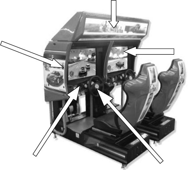
3.3. Name of Parts
Width (cm) Length (cm) Height (cm) Weight (kg)
COCKPIT 82 164.5 152 228
COIN CHUTE TOWER 30.5 51.5 570 15
BILLBOARD 160.9 61.7 35.4 36
When Assembled 163.2 170 186.4 507 approx
13
3.4. Accessories
The machine is supplied with an installation kit. Please ensure the following parts are supplied:
ITEM PART NO. QTY DESCRIPTION
1 ORT-0200UK 1 ASSY BILLBOARD
2 FRI-0300UK 1 ASSY COINCHUTE TOWER FRI
3 ORT-0500UK 1 ASSY WIRE COVER ORT TWIN
4 DYN-0013 1 JOINT PIPE
5 DYN-0006XUK 1 AC COVER B
6 SRT-0018UK 1 AC COVER C
7 DYN-0019UK 1 AC COVER D
8 RAL-XXXX-14UK 1 TIE BRACKET RALLY
9 SPG-0008 2 BILLBOARD HOLDER
10 422-0922UK 1 PLAY INSTR SH ORT TWIN MULTI
11 422-0923UK 1 SUB INSTR SH ORT TWIN MULTI
13 PK0344 1 INST KIT BOX ORT TWIN
18 220-5753 1 VOL CONT B-5K OHM (TOCOS)
19 PK0343 0.5 PALLET INST KIT
101 440-CS0186UK 2 STICKER C EPILEPSY MULTI
201 030-000825-SB 20 M8X25 BLT W/S BLK
202 068-852216-0B 20 M8 WSHR 22OD FLT BLK
203 000-P00412-WB 15 M4X12 MSCR PAN W/FS BLK
204 050-F00400 3 M4 NUT FLG SER PAS
401 420-5827 1 SERVICE MANUAL SANWA 31K
402 420-6796-02UK 1 SERVICE MANUAL ORT TWIN
403 OS1019 2 SELF SEAL BAG 9X12.3/4
404 540-0006-01 1 WRENCH M4 TMP PRF
405 540-0007-01 1 WRENCH M5 TMP PRF
406 540-0009-01 1 WRENCH M8 TMP PRF
407 220-5484 1 VOL CONT B-5K OHM
408 SAECE -xxx 1 DECLARATION OF CONFORMITY
409 514-5078-5000 2 FUSE 5X20 CERAMIC SB 5000mA
411 420-6620UK 1 SERVICE MANUAL GD ROM SYSTEM
416 509-5704 1 SW MICRO TYPE (OMRON K3L13)
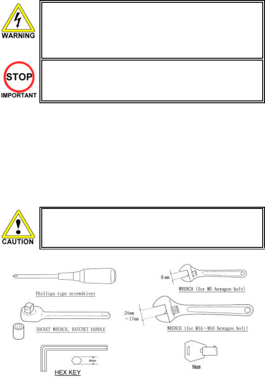
Item 404-406 - Tamper-proof TORX wrench.

14
3.5. Shipping the Game Board
Replacement or repair of the Game Board (Chihiro) for this product should be undertaken at
the appropriate repair centre. Be sure to follow the specifications below when requesting
repairs/sending the board to the repair centre. Not following the specifications may result in
the board not being accepted or in extra charges being made.
• Put the game board in the carton box as is. Do not carry out any disassembly or part
removal other than that specified.
• Follow the procedure and instructions regarding direction below when placing the Game
Board in the carton box.
• When packing the game board with the Media Board attached, do not remove the Key
Chip.
• When packing the game board with the Media Board detached, be sure to include the
AVIP Cable.
• When packing, attach the accessory stickers in the specified places on the Game Board
and carton box.
INSTRUCTIONS
1. Wrap the Chihiro Board in a plastic bag.
2. Place it on top of the bottom surface cushioning material. Turn the Filter Board to face the side with
the three honeycomb buffers. Packing it in the opposite direction may cause damage to the Filter
Board.
3. Insert corrugated cardboard into the space between the lateral honeycomb buffers of the bottom
surface cushioning material and stow the AVIP cable inside.
4. Place the Chihiro Board wrapped in the bottom surface cushioning material into the carton box. Use
the handles on the bottom surface cushioning material.
5. Place the upper surface cushioning material on top of the Chihiro Board. Be sure to align it in the right
direction, as it will not fit otherwise.
6. Close the top of the carton box and seal it tightly with adhesive tape.
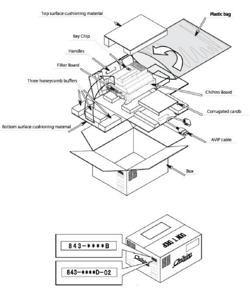
15
16
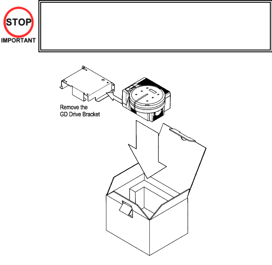
3.6. Shipping the GD-ROM Drive
• When returning the GD-ROM DRIVE for repair or replacement, be sure to package it in
the original card transit box - THERE ARE NO USER-SERVICEABLE PARTS INSIDE.
• Ensure the GD-ROM Disk is removed and the GD-ROM Drive Lid is replaced on the unit,
with fixing screw, before packaging. Also, remove the GD-ROM Drive Bracket and store
with the four screws for reuse.
• Failure to return the GD-ROM DRIVE in this manner may invalidate the warranty.
17
3.7. Assembly Instructions
• Perform the assembly by following the procedure herein stated. Failure to comply
with the instructions, for example, inserting the plug into an outlet at a stage not
mentioned in this manual can cause an electric shock
• Assembling should be performed as per this manual. Since this is a complex
machine, erroneous assembling can cause damage to the machine, or malfunction
to occur.
• Do not attempt to complete this work alone, a minimum of 2 people are required.
• Only QUALIFIED SERVICE PERSONNEL should carry out assembly.
When carrying out the assembly work, follow the procedure in the following 7 item sequence
STEP 1 ASSEMBLING THE COCKPIT
STEP 2 SECURING IN PLACE (LEG ADJUSTER ADJUSTMENT)
STEP 3 BILLBOARD INSTALLATION
STEP 4 INSTALLING THE AC COVERS (WIRE COVERS)
STEP 5 COIN HANDLING INSTALLATION
STEP 6 CONNECTION TO POWER SUPPLY
STEP 7 ASSEMBLY CHECK
Note that the parts contained within the installation kit are required for the assembly work.
• Fit all fixings loosely first as detailed in step 1, then position all components before
finally tightening fixings at step 6.
18
3.7.1. Applying the Play Instructions
• Only QUALIFIED SERVICE PERSONNEL should carry out this operation.
Supplied in the installation kit are 4 sets of play instructions in 5 languages. Select the language of your
choice and apply in the following areas:
1. 422-0922UK: Instructions (on Monitor Mask)
2. 422-0923UK: Instructions (on Control Panel)
19
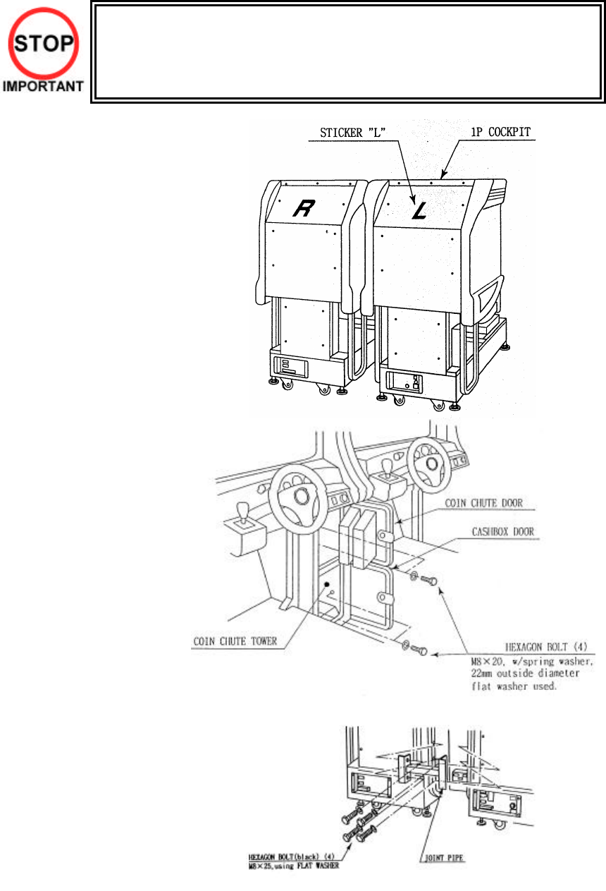
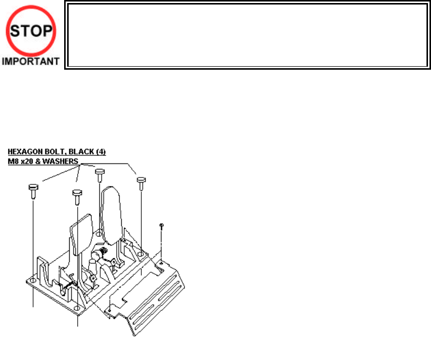
3.7.2. Assembling the Cockpit
• Only QUALIFIED SERVICE PERSONNEL should carry out this operation.
1. Place the two cockpits
side by side. Position the
1P cabinet, which has the
IEC inlet at the left hand
side when viewed facing
the monitor. STICKER L is
attached to the back of the
1P cabinet and STICKER
R on the back of the 2P
cabinet
2. Install the coin chute tower
in between both cabinets.
Open the coin chute door
and the cash door and
secure with the 4 hexagon
bolts from inside the
doors. At this time, make
sure the bolts are only
loosely fitted.
Note: Door may open in opposite way to that shown above
3. Install the joint pipe on the
rear-side of both cabinets
by securing with 4
hexagon bolts, at this time
loosely.
20
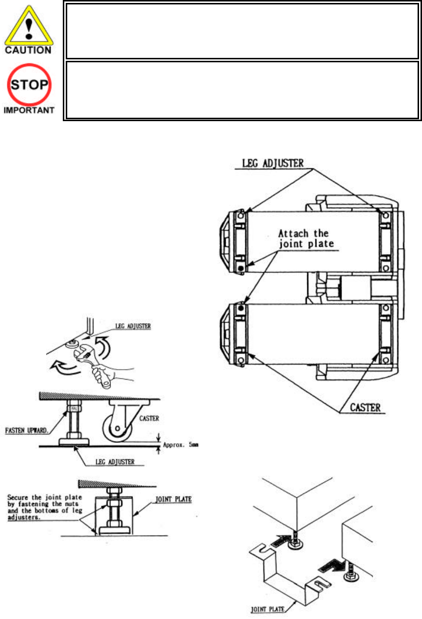
3.7.3. Securing In Place (Leg Adjuster Adjustment)
• Make sure all of the leg adjusters are in contact with the floor. If they are not the
machines may move and cause injury. This operation requires 2 people.
• Only QUALIFIED SERVICE PERSONNEL should carry out this operation.
This machine has eight castors and eight leg adjusters. When the installation position is decided, unscrew
the leg adjusters so that they raise each caster a minimum of 5mm from the floor. Make sure the machine is
level.
1. Move the machine to the installation position.
When installing against or close to a wall, be
sure to allow an adequate space to allow the
player access to the machine.
2. Make the leg adjusters contact the floor.
Adjust using a spanner as shown below so
that a minimum of 5mm exists between the
casters and the floor. Make additional
adjustment so that the machine is level.
3. Slide the joint plate onto the shafts of the
indicated leg adjusters. Tighten the lock nut on
all eight leg adjusters. This will secure the joint
plate.
After securing the leg adjuster bolts, fully tighten all bolts temporarily attached in STEP 1 above.
21
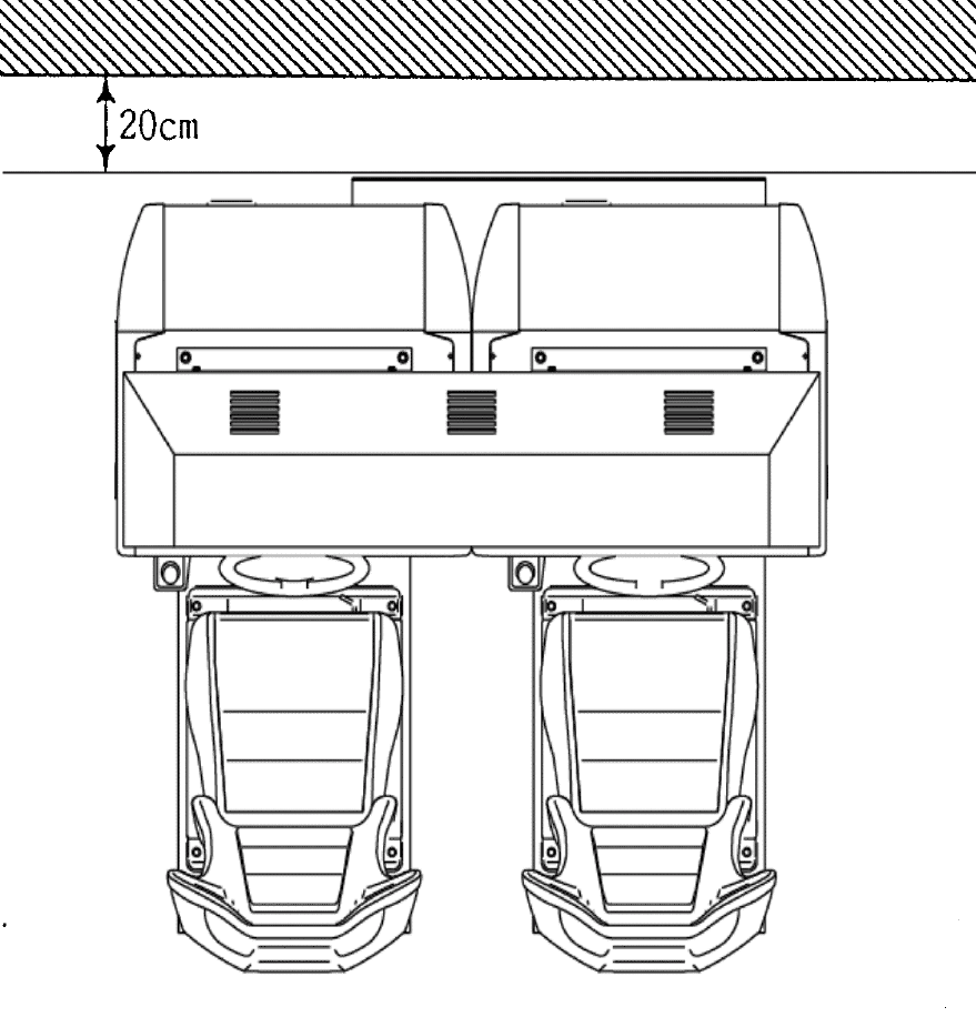
Ensure adequate ventilation is maintained as detailed below
22
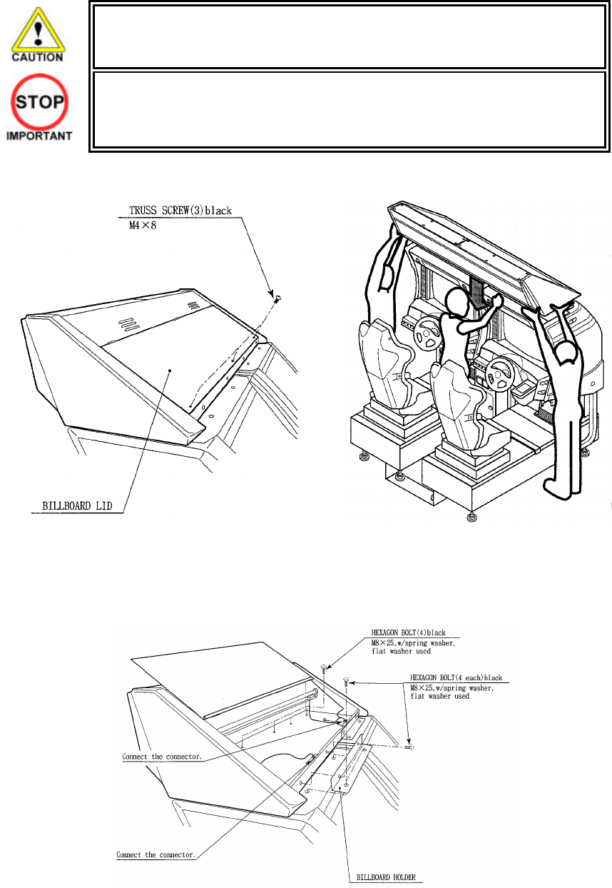
3.7.4. Billboard Installation
• One person alone cannot perform the installation of the billboard assembly. Seek
assistance before attempting this operation
• Only QUALIFIED SERVICE PERSONNEL should carry out this operation.
1. Install the billboard base over the two cockpits.
2. Mount the billboard by fitting it onto the billboard base.
3. Install the billboard holders using 2 hexagon bolts each to secure them to the cabinets.
4. Connect the wire connectors from the billboard box to the connectors on the cabinets and install the
connector covers using two screws for each.
23
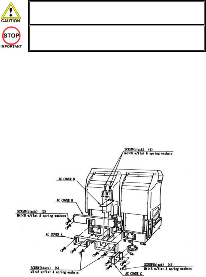
3.7.5. Installing The AC Covers (Wire Covers )
• Be sure that the machine is not connected to the mains supply before attempting
this operation.
• Only QUALIFIED SERVICE PERSONNEL should carry out this operation.
The AC Wire Covers are used for protecting the interconnecting wiring and the fibre optic cables. When
carrying out this operation be very careful so as not to trap any wire between the covers. Pay attention when
handling the fibre optic cables as excessive bending may cause damage.
1. Attach AC Cover A to the rear of the cabinet using 5 screws.
2. Make all the wiring connections between the two cockpits and the Coin Chute Tower. The wiring
connectors are colour coded and cannot be fitted into the wrong size connectors. Do not force any
connectors together.
3. Connect the earth wires between the two AC Brkts, the AC Covers and the Coin Chute Tower.
4. Insert the fibre optic cables into the fibre optic connectors. Ensure that the “RX” connection on the 1P
cockpit is connected to the “TX” connector on the 2P cockpit. The other fibre optic connects the “TX”
connector of the 1P cockpit to the “RX” connector of the 2P cockpit.
5. Insert AC Cover B into AC Cover A from above and secure us ing 2 screws. Be sure not to trap any
cables.
6. Secure AC Cover C and AC Cover D using 4 screws each.
24
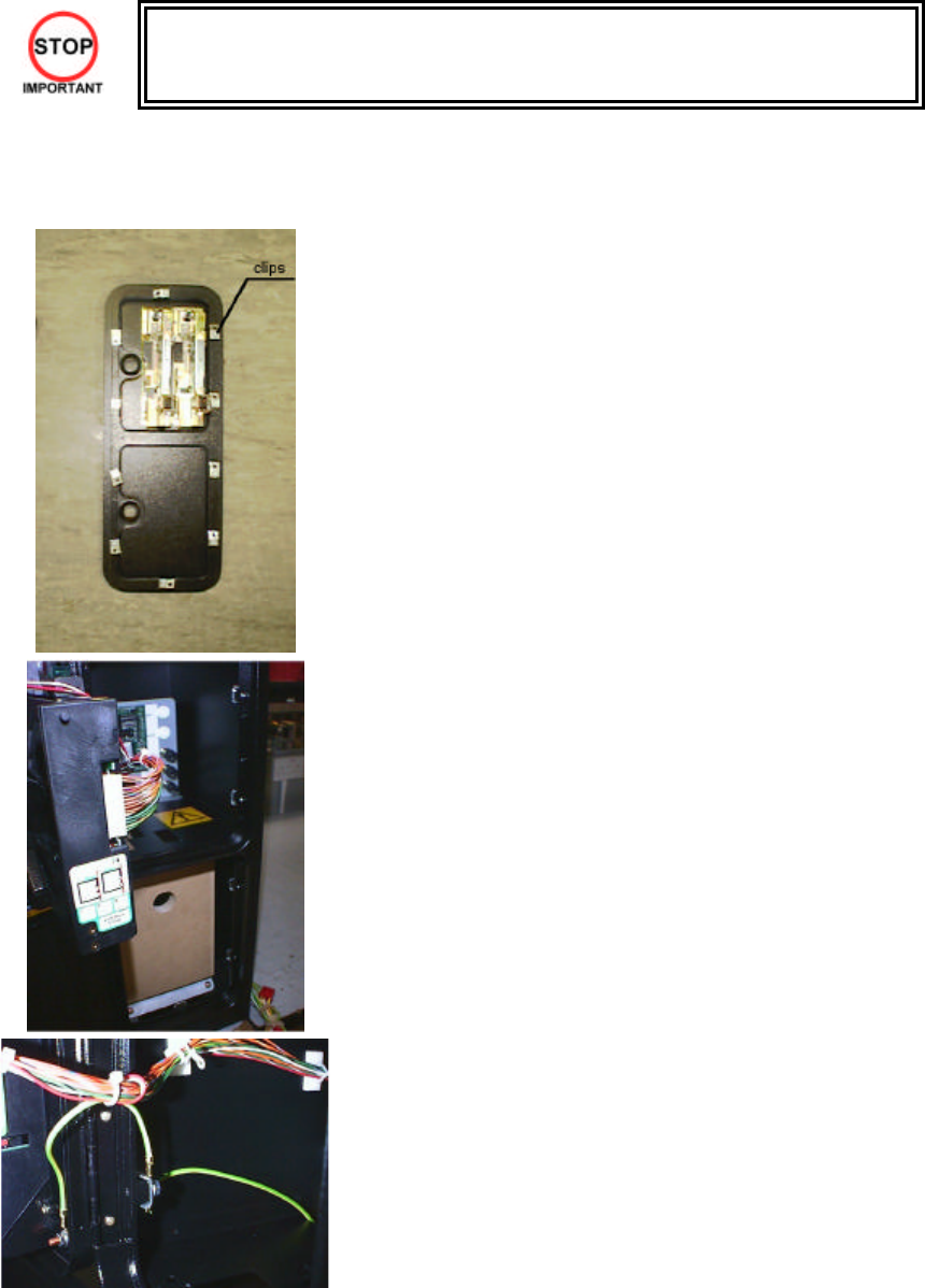
3.7.6. Coin Handling Installation
• Only QUALIFIED SERVICE PERSONNEL should carry out this operation.
When fitting the coin mechanism to the door please refer to the specific manufacturers installation instructions
for that coin mechanism. To fit the door to the machine, follow the procedure below.
• Loosen all of the bolts on the frame, which secure the clips.
• Turn all clips in towards the door.
• Position the door into the aperture in the machine.
• Turn the clips around so that they will hold the door in the
machine.
• Tighten all of the bolts.
• Ensure that the door is earthed to the frame and the frame is
earthed to either the VTS bracket or the coin chute tower.
25
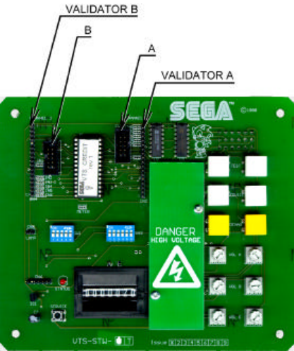
3.7.6.1.Wiring Connections.
COIN MECH LOOM INSTALLATION
C220B LM1006IDC
LM1006LAMP-0.1
• Attach the lamp holder to the bracket on the coin return
button.
• Attach one 15-way connector to the C220 coin mech.
• Attach the other 15-way connector to Validator A on the
credit board.
• Attach the 2-way connector to ‘LAMP’ on the VTS board.
GENERIC
MECHANICALS LM1008
LM1008-LAMP
• Fit the two lamp holders behind the coin return buttons.
• Attach the blue cable and orange cable to one mech’s
microswitch switch.
• Attach the blue/green cable and orange/green cable to
the other mech’s microswitch.
• Attach the 2-way mate and lok plug to the 2-way mate
and lok cap provided.
• Attach one 15-way connector to Validator A and the other
to Validator B on the credit board
MARS MS111B1
MARS ME115
LM1007
LM1008-LAMP
• Fit the lamp holder to the bracket behind the coin return
button.
• Fit one of the 13-way connectors to the coin mech.
• Fit the other 13-way connector to Validator A on the
credit board. Note the 13-way connector is keyed and
this key must coincide with the key on the credit board.
SECI, C120,
SR3 OWN LOOM AND
LM1006LAMP-0.1 • Attach the lamp holder to the bracket on the coin return
button.
• Attach the 2- connector to ‘LAMP’ on the VTS board.
• Attach the validator’s own loom to position A on the credit
board
VTS credit board assembly
26
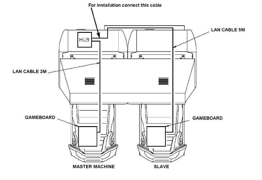
3.7.7. Communication Cables
The master (left) machine’s LAN cable will come pre-connected to hub.
Connect the slave machine’s LAN cable (bundled up at the back in a loop) across via the AC cover to the hub
of the master machine and connect to one of the hub’s ports.
For machine set-up refer to section 3.15.8.1.
27
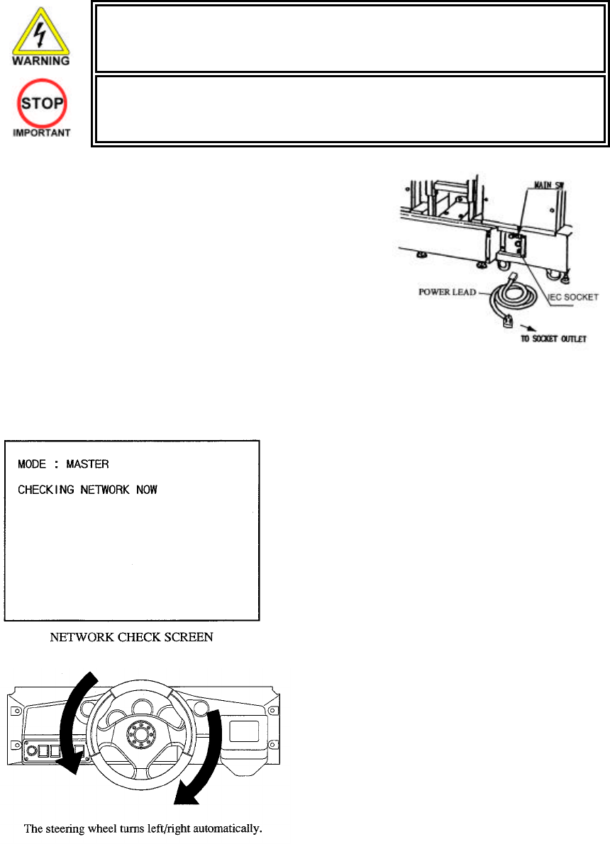
3.7.8. Connection To The Power Supply
• This operation may only be carried out once the machine has been completely
assembled.
• Only QUALIFIED SERVICE PERSONNEL should carry out this operation.
The AC Unit is located on the rear of the 1P cockpit. Using the
power lead supplied connect this to the mains socket at the wall.
1. Turn the mains switch on.
2. Turn the switch on the AC bracket on
3. The machine will start up and go through an initialisation
procedure where the steering wheel turns left and right.
4. DO NOT TOUCH THE MACHINE DURING INITIALISATION. If
the wheel is touched during this time, it could upset the motor
settings and affect the feedback performance during
gameplay.
5. The gameboard will now be checked for approximately one
minute.
6. The network check then start s. After this the attract mode will
appear. If after 30 seconds or so, the network check has not
finished, check the IR communication connections.
28
Fluorescent lamps are always lit
Steering wheels turn both
directions
Control Panel
Sound is
emitted On screen
images are
output
29
3.7.9. Assembly Check
In the Test Mode, ascertain that the assembly has been made correctly and IC BD is satisfactory (see
section 5.2.1).
In the test mode perform the following test:
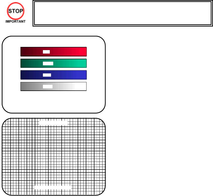
3.7.9.1.CRT Test
• Only QUALIFIED SERVICE PERSONNEL should carry out this operation.
C.R.T TEST
PAGE 1/2
C.R.T. TEST 1/2
PRESS TEST BUTTON TO CONTINUE
RED
GREEN
BLUE
WHITE
In the TEST mode select CRT test to check the
screen is satisfactory.
Although the projector has been set up at the factory
before shipment, check to see if the screen needs
adjustment.
C.R.T. TEST 2/2
PRESS TEST BUTTON TO EXIT

30
3.7.9.2.Memory Test
Selecting RAM TEST or MEDIA BOARD TEST from
the menu screen in System Test mode will cause the
machine to automatically perform a test of memory
on the game boards. If GOOD is displayed next to
the number of each memory segment, the game
boards are working properly.
Select SYSTEM INFORMATION to display
information on the main game board and the media
board. If the information is displayed correctly, this
indicates that the game boards are functioning
properly.
RAM TEST
AUX MEMORY GOOD
TEST BUTTON TO EXIT
MEDIA BOARD TEST 1/2
DIMM BOARD(TYPE 3)
VERSION ****
STATUS GOOD
CHECKING 100%
DIMM TEST
DIMM0 - GOOD
DIMM1 - NONE
GD-ROM - GOOD
PRESS TEST BUTTON TO EXIT
MEDIA BOARD TEST 2/2
NETWORK BOARD
VERSION ****
STATUS GOOD
CHECKING 100%
NETWORK BOARD TEST
RAM CHECK _ GOOD
-- COMPLETED --
PRESS TEST BUTTON TO EXIT
SYSTEM INFORMATION
MAIN BOARD
REGION ****
BOOT VERSION ****
FIRM VERSION ****
FPGA VERSION ****
SERIAL NO. ***************
MEDIA BOARD
DIMM BOARD(TYPE 3) + GDROM
MEMORY SIZE 512MB
FIRM VERSION ****
SERIAL NO. ***************
NETWORK BOARD
FIRM VERSION *****
PRESS TEST BUTTON TO EXIT
31
3.7.9.3.Input Test
Select INPUT TEST from the menu screen in either System Test mode or Game Test mode.
Test the STEERING, GAS (ACCEL) and BRAKE controls to ensure that they are functioning properly and that
the parameters change smoothly as each input device is operated.
Display N, UP and DOWN using the GEAR POSITION. N displays that there is no control input. Verify that
both UP and DOWN display in sync with the position of the shift knob.
Press the START, CHANGE VIEW, SERVICE and TEST Buttons. If functioning correctly, each indicator will
switch from OFF to ON.
Press the SERVICE and TEST Buttons simultaneously to return to the Game Test Menu screen.
JVS TEST
INPUT TEST
NODE 1/1
SYSTEM 00
PLAYER 1 1 0000
PLAYER 2 2 0000
COIN 1 1 0000
COIN 2 2 0000
ANALOG 1 0000
ANALOG 2 0000
ANALOG 3 0000
ANALOG 4 0000
ANALOG 5 0000
ANALOG 6 0000
ANALOG 7 0000
ANALOG 8 0000
32
3.7.9.4.Output Test
Select OUTPUT TEST to display the following screen and check the status of each lamp.
This test should be used periodically to check that the lamps are functioning correctly.
On this screen the cursor will switch automatically between items, lighting up the respective lamps.
• START BUTTON : Lights up the START button.
• VIEW CHANGE BUTTON: Lights up the View Change button.
Press the TEST Button to return to the Game Test Menu screen.
3.7.9.5.Sound Test
In the system test mode, selecting SOUND TEST
causes the screen (on which sound related BD and
wiring connections are tested) to be displayed.
Check if the sound is satisfactorily emitted from each
speaker and the sound volume is appropriate.
SOUND TEST
OUTPUT TYPE STEREO
RIGHT SPEAKER OFF
LEFT SPEAKER OFF
àEXIT
SELECT WITH SERVICE BUTTON
AND PRESS TEST BUTTON
33
3.7.10. Moving The Machine
• When moving the machine, be sure to remove the plug from the power supply. Moving the
machine with the plug inserted can cause the power cord to be damaged, resulting in a
fire or electric shock.
• When moving the machine, retract the leg adjusters fully and ensure the casters make
contact with the floor. During movement pay careful attention so that the casters or leg
adjusters do not damage any other cabling laid on the floor. Such damage could result in
a fire or electric shock.
• Don’t push the cockpit cabinets from the side, as they may topple and cause damage.
• Don’t put excessive pressure on the glass or plastic components as damage or personal
injury may result if there is a breakage.
• Only QUALIFIED SERVICE PERSONNEL should carry out this operation.
Disassemble the cabinet into its components if
transporting up or down step level changes!
Do not push an individual cockpit from the side!
34
3.8. Fuses
• Never touch places other than those specified. Touching places other than those
specified can cause electric shock and short circuit. Disconnect the machine from
the supply before attempting the replacement of any fuse.
• Only QUALIFIED SERVICE PERSONNEL should replace FUSES.
There are a number of fuses used on this machine to protect the user and the machine from damage. Only
replace the fuse once you have remove the cause of its failure. Detailed below is a list of the fuses used, their
location and if relevant PCB reference:
PART NUMBER LOCATION TYPE & DETAILS QTY PER COCKPIT
514-5078-10000 IEC INLET (EP1302) 5X20 HRC SB 10000 mA 1 (PER TWIN)
514-5078-6300 838-11856CE-02 5X20 HRC SB 6300 mA 1
514-5078-6300 838-13578(F1) 5X20 HRC SB 6300 mA 1
514-5080-15000 838-14174(F1) 32X6.35 HRC SB 15000 mA 1
514-5078-2500 838-14174(F2) 5X20 HRC SB 2500 mA 1
There are also fuses located on the Monitor PCB. Refer to the relevant Monitor manual supplied to reference
these fuses.
RATED VOLTAGE: 220-240 VAC
RATED CURRENT: 3 Amps.
35
3.9. Maintenance
• Only Qualified Service Personnel must carry out maintenance.
• Ensure that the mains power is switch OFF and disconnected before attempting any
work.
• The CONTROL PANEL ASSEMBLY is heavy and may cause injury or damage to the
machine if dropped. Use an assistant when removing and replacing it.
• In order to prevent an electric shock and short circuit, be sure to turn power off before
performing work by touching the interior parts of the product.
• Be careful not to damage the wires. Damaged wires may cause electric shock or short
circuit or present a fire risk.
• Do not touch undesignated places. Touching places not designated can cause electric
shock or short circuit.
• This work should be performed by the site maintenance individual or other skilled
professional. Performing work by non-technical personnel can cause electric shock
hazard.
• Do not perform work other than those specified in this Manual in order to prevent
accidents during performing work and operation after performing work. Performing work
not specified in this Manual may require special training for this product. If performing
work other than those stated in this manual is required for repair, contact the offices
herein stated in this manual or where you purchased the product from and ask for repair
or inquire how to repair.
• Be very careful when soldering. Handling a soldering iron carelessly may result in a fire or
a burn.
• Be extremely careful when heating the heat-shrinkable tube. Failure to do so may result
in a fire or burns.
• Do not drop parts when removing them. Dropping parts may damage them or cause
sudden accidents.
• To prevent accidents, more than one person must perform these operations.
• Exercise extreme caution when handling the internal parts of the Control Panel. Watch
out for damage, warping and loss. The loss of just one piece may result in damage to or
lead to faulty operation of the entire unit.
• When securing the plastic-made parts, do not excessively fasten screws and nuts.
Failure to observe this may damage the parts and cause injury due to fragments resulting
from damage.
• Be sure to perform volume's move value setting in the Volume Setting in the Test Mode
after replacing or adjusting the Volume. (See 5.3.1)
36
3.9.1. Handle Mecha
In the TEST MODE, if the steering wheel V.R. variations are not within the allowable limit, the V.R. installation
position requires adjustment or the V.R. needs replacement. Also be sure to apply grease every 3 months.
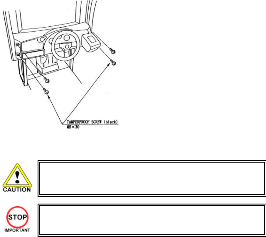
3.9.1.1.Removing the Handle Mecha
1. Turn the POWER switch OFF
2. Remove a total of 4 tamperproof screws from
the Control Panel
3. Wiring connectors are connected inside the
Control Panel. Carefully withdraw the control
panel in a manner so as not to damage the
wiring.
4. Disconnect the wiring connectors and earth
harness.
3.9.1.2.Replacing and Adjusting The Handle Mecha’s V.R.
• Never touch places other than those specified. Touching places other than those
specified can cause electric shock and short circuit.
• After the replacement or adjustment of the V.R. be sure to set the Centre of Steer in the
DRIVE BOARD TEST.
37
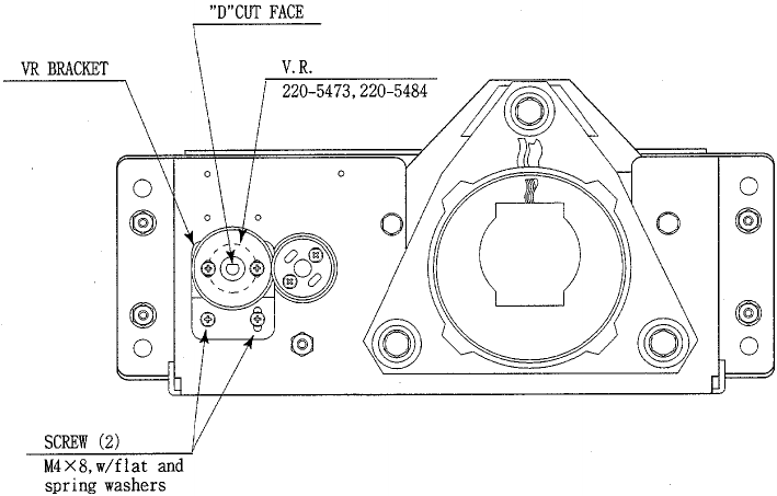
3.9.1.3.Adjusting the VR
Remove the CONTROL PANEL as detailed above. Locate the V.R. on the rear surface of the HANDLE
MECHA.
1. Using a screwdriver, loosen the 2 machine screws which secure the V.R. Bracket. Move the V.R.
Bracket so as to disengage the gears.
2. Gently rotate the V.R. until its value is within the range of the centring position. Position the steering
wheel in the centre position.
3. Mesh the gears together. Make sure that a correct amount of backlash is maintained between the gears.
4. If the V.R. value is still not correct make fine adjustments by loosening the 2 machine screws on the
V.R. gear. Rotate the gear holder until the correct value is obtained.
5. The value should be adjusted such that with the steering wheel in the centre position the value read
during INPUT TEST shall be 80H±10H.
6. Re-set the centre of steer as described in the game test mode (output test).
3.9.1.4.Replacing the VR
1. Remove the CONTROL PANEL as detailed above. Locate the V.R. on the rear surface of the HANDLE
MECHA
2. Using a screwdriver, remove the 2 machine screws which secure the V.R. Bracket. Remove the V.R.
Bracket so as to disengage the gears.
3. Loosen the hexagon drive grub screws in the collar and gently slide off the V.R.
4. Reassemble is the reverse procedure of steps 1 and 2 above.
5. When complete you must readjust the V.R. in accordance with the paragraph above.
38
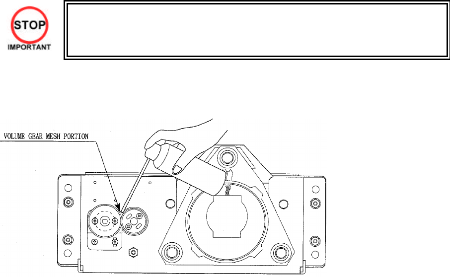
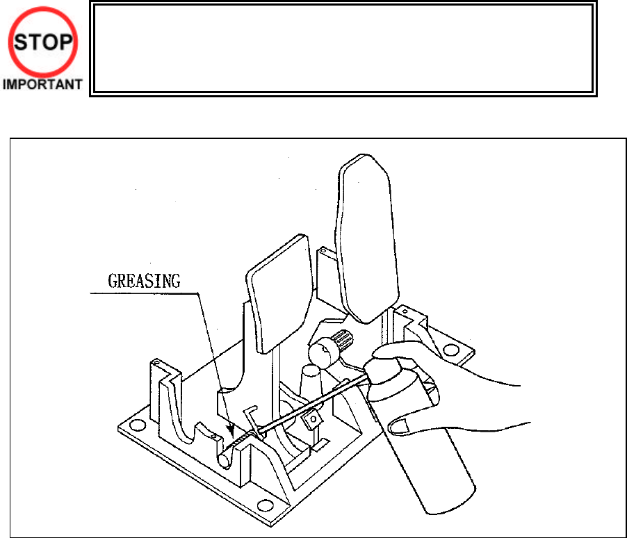
3.9.1.5.Greasing
• Be sure to use a good quality, synthetic lubricant. Using a mineral-based lubricant will
cause damage to the plastic parts.
• Do not apply lubricant to parts other than those specified. Doing so may cause damage
or deterioration of parts.
Apply lubricant to gear mesh portions once every 3 months.
39
3.9.2. Accelerator & Brake
• Only Qualified Service Personnel must carry out maintenance. Ensure that the
mains power is switched OFF and disconnected before attempting any work.
In the TEST MODE, if the brake or accelerator V.R. variations are not within the allowable limit, the V.R.
installation position requires adjustment or the V.R. needs replacement. Also be sure to apply grease to all
moving parts every 3 months.
3.9.2.1.Removing the Accelerator & Brake.
1. Turn the POWER switch OFF
2. Remove a total of 4 screws securing the
covers over the ACCELERATOR & BRAKE
3. Fine adjustment of the V.R. values is
accomplished with just these covers removed.
4. Coarse adjustment requires the
ACCELERATOR & BRAKE mounting bolts to
be removed. If this is necessary, remove the
bolts from the unit, but do not remove the unit
from the machine. Take extreme care when
operating the unit in this condition as damage
to other components can occur.
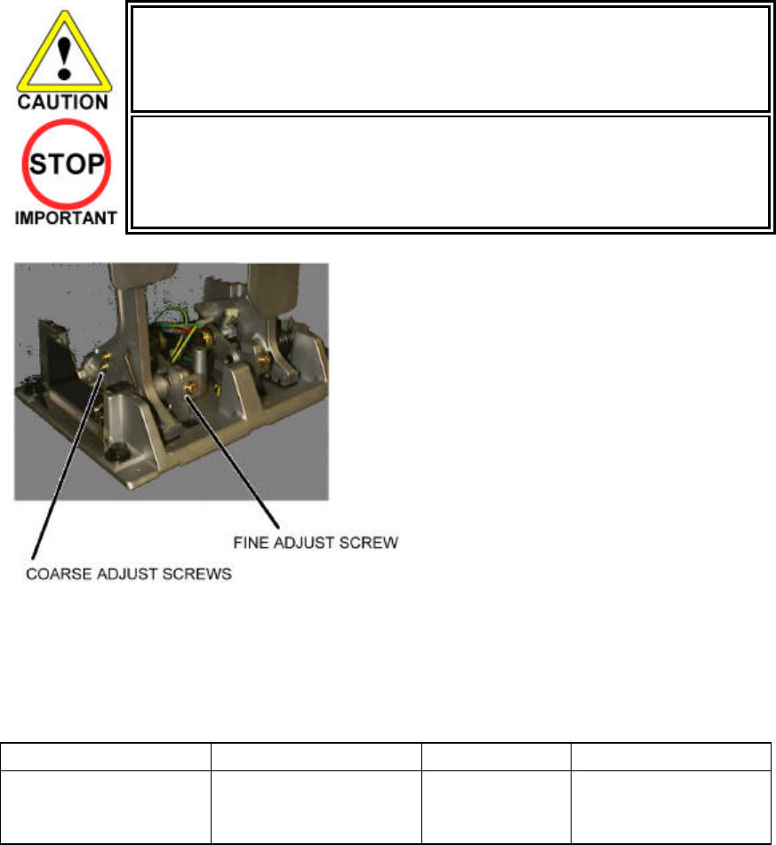
40
3.9.2.2.Adjusting the V.R.
• Never touch places other than those specified. Touching places other than those
specified can cause electric shock and short circuit.
• After the replacement or adjustment of the V.R. be sure to set the values in the
INPUT TEST.
1. Remove the cover panels as detailed above.
2. Fine Adjustment - By using a screwdriver loosen
the 2 machine screws that secure the V.R. arm.
Move the V.R. arm to adjust the V.R. value within
the relaxed range.
3. Coarse Adjustment - Remove the four hexagon
bolts detailed above and remove the side covers
of the Accelerator & Brake.
4. Loosen the two machine screws holding the V.R.
rack
5. Move the V.R. rack away so as to disengage the
V.R.
6. Gently rotate the V.R. until its value is within the
range of the centring position.
7. Mesh the gears together. Make sure that a
correct amount of backlash is maintained.
8. If the V.R. value is still not correct make fine
adjustments as detailed above.
The required values are:
GAS PEDAL: Under 30H ⇒ Over C0H
BRAKE PEDAL: Under 30H
(THE PEDAL RELEASED)
⇒ Over C0H
(THE PEDAL
PRESSED)
41
3.9.2.3.Replacing the V.R.
1. Loosen and withdraw the V.R. rack as detailed above.
2. Using a hexagon key loosen the two grub screws holding the V.R. gear onto the V.R.
3. Remove the V.R. gear
4. Using a spanner remove the nut holding the V.R. in position.
5. Gently remove the V.R. and its wire harness.
6. Refit is the reverse of removal.
7. When complete you must readjust the V.R. in accordance with the paragraph above.
3.9.2.4.Greasing
• Be sure to use a good quality, synthetic lubricant. Using a mineral-based lubricant
will cause damage to the plastic parts.
• Do not apply lubricant to parts other than those specified. Doing so may cause
damage or deterioration of parts.
Apply lubricant to gear mesh portions once every 3 months.
42
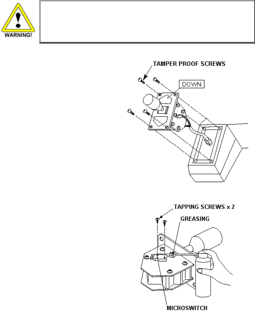
3.10. Shift Lever
In the Test Mode, if the SHIFT LEVER's SW can not be inputted satisfactorily, replace the Switch. Apply
greasing to the Mechanism's sliding portion once every 3 months.
When performing the above work, remove the Shift Lever Unit.
• Before starting to work, ensure that the Power SW is OFF. Failure to observe this
can cause electric shock and short circuit hazards.
• Use care so as not to damage wirings. Damaged wiring can cause electric shock
and short circuit hazards.
REMOVING THE SHIFT LEVER
A) Turn the Power SW off.
B) Remove the 4 Tamperproof Screws to lift the
Shift Lever Unit.
C) Disconnect the Connector to remove the
Shift Lever Unit.
D) When reinstalling, follow the procedure
opposite as when removing. At this time,
ensure that "DOWN" display appears on the
upper part as shown.
E) After reinstalling, be sure to check INPUT
TEST in the test mode. (TEST.)
SWITCH REPLACEMENT
A) Disconnect the wiring Connector of the
Switch to be replaced.
B)
Remove the 2 Tapping Screws to replace the
Microswitch.
GREASING
Apply greasing once in 3 months to the specified
portions.
For spray grease, use NOK KLUBER L 60 or
Grease Mate (Part No. 090-0066).
43
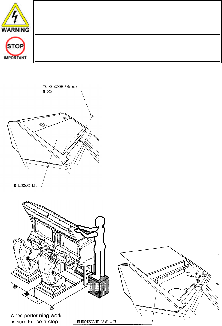
3.11. Replacement of Fluorescent Lamp and Other Lamps
• Never touch places other than those specified. Touching places other than those
specified can cause electric shock and short circuit. Disconnect the machine from
the supply before attempting the replacement of any lamp.
• Prepare a secure step when working on the upper parts of the machine.
• Only QUALIFIED SERVICE PERSONNEL should replace lamps.
3.11.1.Fluorescent Lamp Replacement
1. Turn the POWER switch OFF.
2. Take out the 3 screws and open the Billboard lid.
3. Remove the end caps from the fluorescent tube.
4. Pull the tube out of the clips with a twisting action.
44
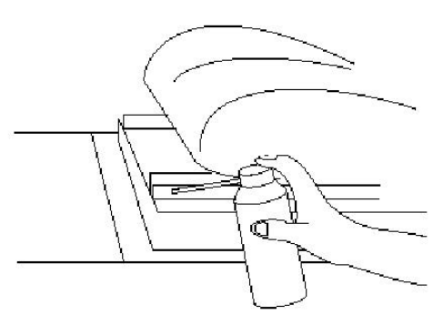
3.12. Cleaning the Cabinet Surfaces
When the cabinet surfaces are badly soiled, remove stains with a soft cloth dipped in water or diluted
(with water) chemical detergent and squeezed dry. To avoid damaging surface finish, do not use such
solvents as thinner, benzine, etc. other than ethyl alcohol, or abrasives, bleaching agent and chemical
dustcloth.
3.13. Seat (Greasing to Seat Rail Portion)
Move the Seat to the rearmost position and
apply spray greasing to the portion shown
at the right once every 3 months by using
NOK KLUBER L60 or GREASE MATE
SEGA PART No. 090-0066.
After greasing, move the Seat a few times
forward and backward so as to allow the
grease to be applied all over uniformly. Be
sure to wipe grease which attaches to the
surfaces of the PROTECT RUBBER on the
Seat Rail, or any excess grease.
45
3.14. Troubleshooting
• Only QUALIFIED SERVICE PERSONNEL should carry out these procedures.
3.14.1.Troubleshooting (When No Error Message Is Shown)
• In order to prevent electric shock and short circuit, be sure to turn power off before
performing work.
• Be careful so as not to damage wirings. Damaged wiring can cause electric shock or
short circuit.
• After removing the cause of the functioning of the Circuit Protector, reinstate the
Circuit Protector. Depending on the cause of the functioning, using the Circuit
Protector as is without removing the cause can cause generation of heat and fire
hazard.
• In the event that a problem cannot be resolved by employing the procedures listed in
this Manual, be sure to request service from the office shown on this Manual or the
dealer from whom the product was originally purchased. Attempts to employ
procedures other than those specified in this Manual can cause electrical shock,
shorting, or fire.
• In the event of a problem that is not described here, be sure to contact the office
shown on this Manual or the dealer from whom the product was originally purchased.
Careless attempts at repair can result in electrical shock, shorting, or fire.
If a problem occurs, first check to make sure that the wiring connectors are properly connected.
PROBLEM CAUSE COUNTER MEASURES
The power is not ON. Firmly insert the plug into the outlet.
Incorrect power source/voltage. Make sure that the power
supply/voltage are correct.
When the main SW is
turned ON, the machine is
not activated.
The fuse of the connect board was blown out
due to momentary overcurrent.
After eliminating the cause of overload,
replace the specified rating fuse.
Connector connection fault. Check connector connections
between the Cabinet and the FL box.
Fluorescent lamp inside
FL box doesn't light up.
Fluorescent lamp and Glow lamp need
replacement. Replace the fluorescent lamp and the
glow lamp (See Section 3.7.9)

46
PROBLEM CAUSE COUNTER MEASURES
Sound volume adjustment is not
correct. Adjust the Switch Unit's sound adjustment
volume . (See Section 5.1.1)
Faulty connections for various
connectors. Check the connections for the game board,
amp, speakers and Volume connectors.
Sound is not emitted.
Malfunctioning BD, Amp. and
Speaker. Perform SOUND TEST. (See 5.2.3)
Faulty connections for the visual
signal connector or the monitor power
connector.
Check the connections for the monitor and
game board connectors.
Sounds are emitted and
the lamps are lit, but the
screen is black.
Broken monitor. Contact the company from whom the unit
was purchased.
Irregular/uneven colors on
the monitor screen. Magnetization of the CRT. Press the Degauss. switch on the VTS
Assembly (See Section 5.1.1.)
Faulty connection for the visual signal
connector.
Check the visual signal connector connection
and make sure it is secured properly.
Colors on the monitor
screen are strange.
Screen adjustment is not appropriate.
M
ake adjustment appropriately. (See Monitor
Manual)
The on-screen image
sways and/or shrinks. The power source and voltage are no
correct. Make sure that the power supply and voltage
are correct.
Check the connection for the I/O Board and
Cabinet connector.
Does not accept input from
any switch or volume. Faulty connector connections.
Check the power for the I/O Board.
Faulty connector connections. Check the connections for the connectors in
the Control Panel and between the Control
Panel and the Cabinet.
Does not accept input from
the Shift Lever.
Broken Microswitch. Replace the Microswitch
Incomplete power on check. Power on and verify that the power on check
completes properly. (See 3.7.8)
Deviation of the volume value. Adjust the volume value in the Test Mode.
Volume gear engagement fault. Adjust the engagement of the gear. (See
Section 3.9.1.3)
Volume malfunctioning. Replace the volume. (See 3.9.1.4)
STEERING (Servomotor)
response is incorrect.
Detached wires. Check for faulty wire connections around
moving parts.
When replacing wires, secure them so that
they do not touch any moving parts.

47
PROBLEM CAUSE COUNTER MEASURES
Failure of power-on checking
procedure. Reconnect the power and complete a
power-on checking procedure. (See
Section 3.7.8)
Faulty connector connections. Check the connections for the connectors
between the Game Board and Servodriver
and between the Servodriver and the
Servomotor.
Thermal element in the Servodriver
is operating. Occurs when the internal temperature
reaches 70°C (158°F) and corrects
automatically when the unit cools.
No response from Steering
(Servomotor).
Momentary overload caus ed a fuse
on the Servodriver to blow. Contact the company from whom the unit
was purchased.
Steering (Servomotor) is
week in its force feedback. Aging of the force feedback
mechanism. Reset in the Test Mode. ( See 5.3.1)
Incorrect volume setting. Adjust the volume value in the Test Mode.
(See 3.9.2.2)
Faulty Volume attachment or adjust
gear alignment. Adjust the volume attachment and verify in
Test Mode. (See Section 3.9.2.2)
Faulty connector connection. Check the connections for the Accel and
Brake connectors and the connectors
between the Accel, Brake and Cabinet.
Unsatisfactory Accel and
Brake operation.
Failure of the volume. Replace the volume. (See 3.9.2.3)
Start button and Change
View button input does not
work and they do not flash.
Faulty connector connections. Check the connections for the connectors
between the I/O Board, the Cabinet and
the Control Panel and those inside the
Control Panel.
Unverified settings or operation. The Start button only flashes when Free
Play is set. Check the operation in Test
Mode.
(See Section 5.3.1)
Start button and Change
View button input works, but
they do not flash.
The lamp is burnt out. Replace the lamp.
Network play is wrongly set. Reset correctly. (See Section 3.15.8)
Communication cables are wrongly
connected.
Communication cables are
disconnected.
Reconnect the cables.
(See Sections 3.7.7 & 3.15.8)
Failure of the network play.
Damage of communication cables.
Reconnect cables correctly. (See Section
3.15.8)
Replace the cables. Contact the company
from whom the unit was purchased.
48
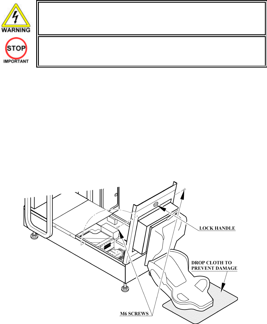
3.15. Gameboard
• Turn off the mains power and remove the power cord before opening the machine.
• The GAME BOARD should not require any work to be carried out upon it. All settings
and tests can be achieved without access to the GAME BOARD.
• All work to be carried out by QUALIFIED SERVICE PERSONNEL
3.15.1.Removing the Board
To return the game board for servicing, take out the board using the following procedure.
1. Turn the main switch OFF.
2. Unlock the base and remove the 2 M6 bolts.
3. Tip the seat carefully backwards as shown. Be careful not to damage the seat back when resting it on the
floor. Use a protective mat under the seat back to protect it on hard floors.
4. Disconnect all connectors from the game board, remove the four screws securing the game board to the
wooden base, and lift it out. Do not attempt to service the game board. THERE ARE NO USER
SERVICEABLE PARTS INSIDE! Return the game board to the Service Department inside the special
packaging provided.
Note.
Triforce game board is shown
however a Chihiro board is fitted.
49
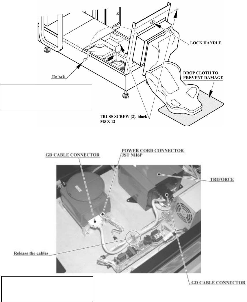
3.15.2.Removing The GD-ROM Drive
1. Turn the power off.
2. Remove 1 truss screw from each side of Base Lid R.
3. Unlock the base with the Master Key.
4. Turn the Lock Handle on Base Lid R to unlock the lid.
5. Lower the seat towards the backrest. Slowly lower the backrest until it touches the floor to prevent
damage to the seat part. Put a drop cloth on the floor to prevent damaging the surface of the seat
part.
6. Remove the GD cable connector and the power cord connector from the GD-ROM drive.
Note:
Triforce game board is shown,
however a Chihiro is fitted.
Note:
Triforce game board is shown,
however a Chihiro is fitted.
50
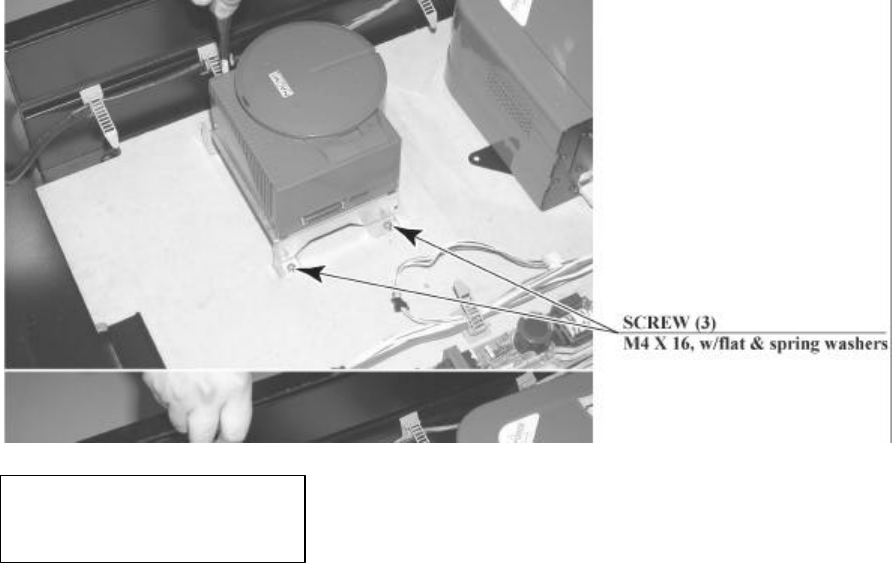
7. Remove the 4 screws to remove the GD-ROM drive.
Note:
Triforce game board is shown,
however a Chihiro is fitted.
51
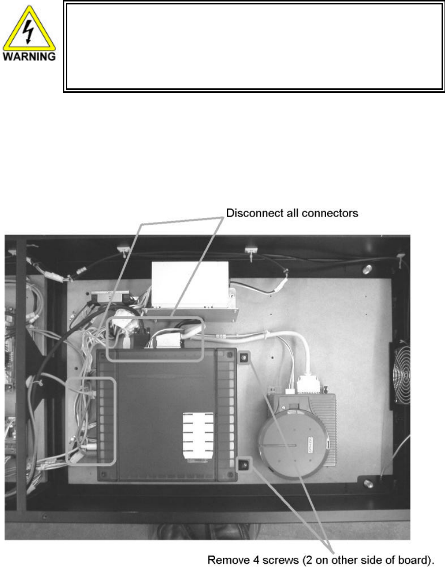
3.15.3.Removing The Game Board
• When returning the game board for replacement or repair, make sure that the connectors
are attached correctly. Incorrect connections can lead to accidents such as electric
shock, short circuits, and/or fire.
• When plugging in connectors, pay close attention to the direction of the connection. The
connectors are designed to be connected in a specific direction. Attempting to plug in a
connector by applying excessive force may damage the connector or its terminal clasp,
possibly resulting in electric shock, short circuits, and/or fire.
1. Follow the above described action 1 to 5.
2. Remove all the connectors from the game board.
3. Remove the 4 screws that fix the game board.
52
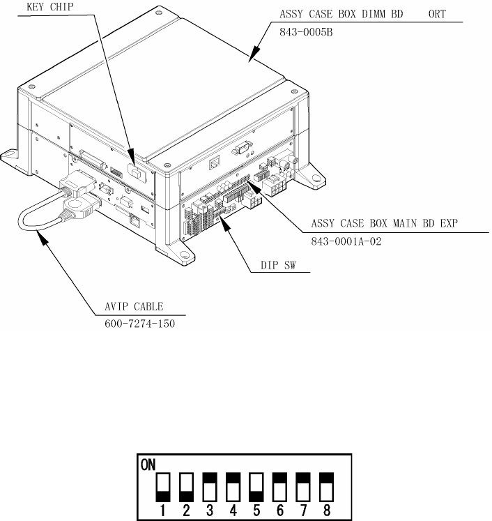
3.15.4.Composition of the Game Board
Once the Chihiro Board has the Key Chip inserted, it is this product's specialized Game Board.
ASSY CASE BOX ORT EXP 843-0005D-02
DIP SW SETTING
Use this product with the DIP SW settings shown in the figure below.
53
3.15.4.1.Replacing The Main Board Battery
• To prevent overheating, explosion, or fire:
• Do not recharge, disassemble, heat, incinerate, or short the battery.
• Do not allow the battery to com e into direct contact with metallic objects or
other batteries.
• To preserve or to dispose of the battery, wrap it in tape or other insulating
material.
• Follow local regulations when disposing of the battery.
Improper disposal can damage the environment.
• To avoid risk of malfunction and damage:
• Make sure the positive and negative ends are aligned correctly.
• Use only batteries approved for use with this unit.
• If an error appears indicating that the battery power is very low within the first year
of use, it is usually an indication of a problem or abnormality with something other
than the battery. Be sure to inspect the board that the battery is connected to.
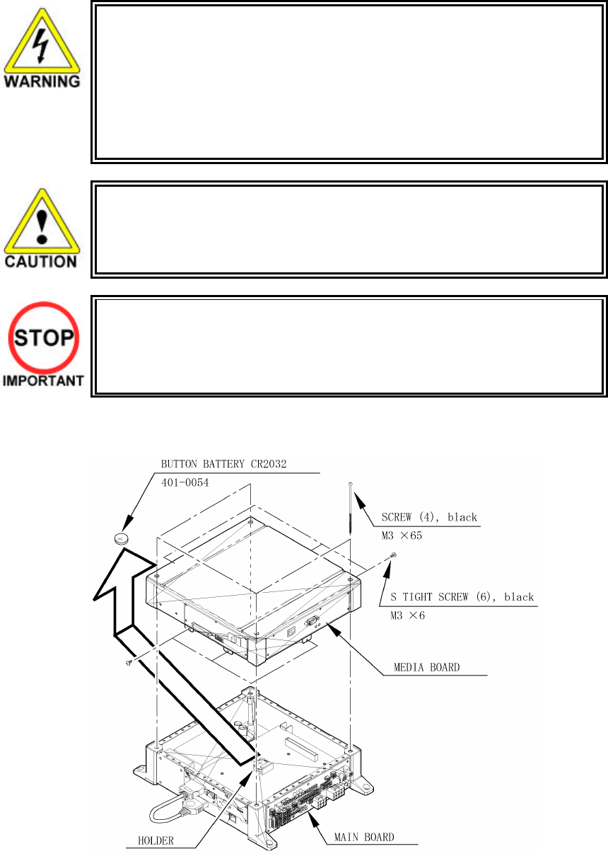
There is a Media Board Button Battery underneath the Media Board.
• Carefully remove the battery from its holder.
• Insert a new battery into the holder with the "+" terminal facing up.

54
3.15.4.2.Replacing The Media Board Battery Pack
Prohibitions and Cautions to Handle the Battery Pack
• Be careful when handling the battery pack.
• We bear no responsibility for problems caused by handling clearly contrary to the content of this
manual.
• Do not disassemble the battery pack and the batteries.
• If you should fail to observe this instruction, the internal wires and/or protective
devices may be damaged; as a result the safety system may not function when
discharging and recharging, eventually causing an overheating, fire and explosion. If
you should disassemble the batteries, the generated gases may harm your throat
and the negative plate may overheat and make a fire.
• Do not make an external short circuit of the battery pack and the batteries.
If you should fail to observe this instruction, the batteries may overheat, make a
fire, and explode.
• Do not fire the battery pack and the batteries.
If you should fail to observe this instruction, the batteries may make a fire and
explode.
• Do not leave the battery pack and the batteries nearby the heat source (fire or
heater) or under the intense direct sunlight and flaming sun.
If you should fail to observe this instruction, the batteries may reduce the service
life and in the worst case may overheat, make a fire, and explode.
• Do not leave the battery pack and the batteries in water or seawater. Also do not
apply water or seawater onto the battery pack and the batteries. If you should fail to
observe this instruction, the internal wires and/or protective devices may be
damaged; as a result the safety system may not function when discharging and
recharging, eventually causing an overheating, fire and explosion. Also water may
be electrolyzed into oxygen and hydrogen, and eventually the battery's sealed
section may be corroded and the internal liquid may leak.
• Do not solder on the battery pack's terminals.
If you should fail to observe this instruction, the a
rmor may be heated and melted or
the internal wires may be damaged, eventually causing an overheating, fire and
explosion. Also, when the battery's temperature reaches to 100•Ž or more, the
battery may leak its internal liquid due to destruction of its plastic parts (gasket,
separator, etc.), or may overheat, make a fire, or explode due to internal short-
circuit.
• Do not insert or connect the battery in a reversal polarity.
If you should fail to observe this instruction, the battery may be externally short-
circuited and eventually overheat, make a fire, or explode, depending on the device
you connect with.

55
• Do not tightly seal the battery pack when installing it onto an external device.
• Flammable gas is generated from the battery when its safety mechanism has
functioned. If you should fail to observe the above-described instruction, sparks
from motors, switches, etc. may cause the gas to fire. Therefore, install the battery
pack so that the gas can be quickly released from the external device.
• Do not use the battery pack for the device/usage other than this game system.
If you should fail to observe this instruction, the battery and/or the device may be
damaged due to non-applicable specifications.
• Do not strike a nail in, hammer, step on, or apply any other forms of pressures and
shocks on, the battery.
If you should fail to observe this instruction, the battery may be deformed. As a
result, the battery may burst at its sealed sections to leak the internal liquid, or
may be short-circuited internally to overheat, make a fire, and explode.
• Do not use a battery charger because any battery charger is not usable for this
battery pack.
If you should fail to observe this instruction, the gas may be suddenly generated in
the battery and eventually the battery may overheat, make a fire or explode.
• If the battery in use or in keeping shows an abnormal indication (deformation,
change of color, bursting of the armor cover, etc.), immediately stop using or
keeping it. If it leaks and smells abnormally, immediately keep it away from fire and
put it in a safety box.
• If the liquid leaks from the battery and gets in your eyes, do not rub your eyes but
immediately wash them with clean water (city water etc.); and consult a medical
doctor for a treatment. If you should fail to observe this instruction, the liquid may
harm your eyes.
• The battery pack armor (a polyvinyl chloride tube) may be damaged or deformed by
external force or heat. When transporting the battery pack or replacing it with a new
one, therefore, be careful not to drop or excessively shock it. Do not continue to
use any damaged or deformed battery pack. If you should fail to observe this
instruction, the battery may overheat, make a fore, or explode.
• The battery pack contains a printed circuit board (PCB) for protective circuitry. It
may be destroyed by the static electricity. When handling or servicing the battery
pack, therefore, take preventive measures against the static electricity.
• If your battery pack has shown destruction of a protective circuitry PCB, do not
continue to use it. If you should fail to observe this instruction, the battery may
overheat, make a fore, or explode.
• When wiring the battery pack to a device, be careful not to apply excessive force
onto the connectors and lead wires. The battery may overheat, make a fire, or
explode if the connectors and lead wires are damaged.
• When discarding the battery pack at a disposal specialist, be sure to cover the
terminals with tape or some other covering and avoid damage when packing.
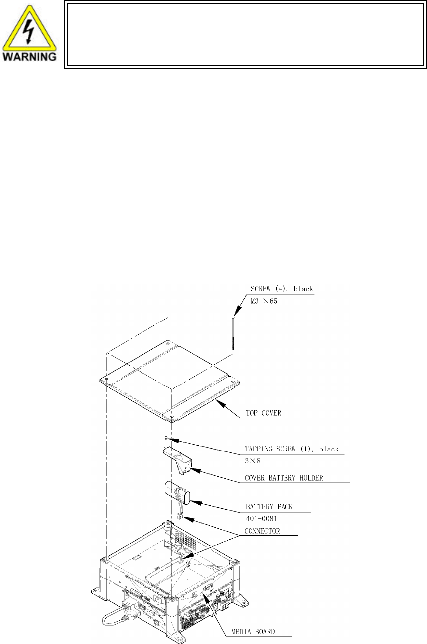
56
• Do not do away with the used battery packs carelessly because they may
contaminate the environment. Be sure to dispose of the used battery packs in
accordance with the laws/regulations of your country.
If the GD-ROM read time becomes excessively long, it is likely that the Media Board battery pack life if
running low.
No battery pack charger is available.
Follow the procedure to replace the battery pack:
1. Remove 4 screws from the upper face of the board.
2. Remove the top cover.
3. Remove 1 tapping screw and remove the cover battery holder.
4. Disconnect the connector at the end of the wire coming out of the battery pack. Remove by pressing
the projection on the connector and pulling.
5. Securely connect the new battery pack.
6. Attach the cover battery holder and top cover.
Submit the used battery packs to an industrial waste disposal plant. Thus they must be disposed according
to the local laws and the regulations in your country.

57
3.15.5.Shipping The Game Board
Replacement or repair of the Game Board (Chihiro) for this product should be undertaken at
the appropriate repair centre. Be sure to follow the specifications below when requesting
repairs/sending the board to the repair centre. Not following the specifications may result in
the board not being accepted or in extra charges being made.
• Put the game board in the carton box as is. Do not carry out any disassembly or part
removal other than that specified.
• Follow the procedure and instructions regarding direction below when placing the Game
Board in the carton box.
• When packing the game board with the Media Board attached, do not remove the Key
Chip.
• When packing the game board with the Media Board detached, be sure to include the
AVIP Cable.
• When packing, attach the accessory stickers in the specified places on the Game Board
and carton box.
INSTRUCTIONS
1. Wrap the Chihiro Board in a plastic bag.
2. Place it on top of the bottom surface cushioning material. Turn the Filter Board to face the side with the
three honeycomb buffers. Packing it in the opposite direction may cause damage to the Filter Board.
3. Insert corrugated cardboard into the space between the lateral honeycomb buffers of the bottom surface
cushioning material and stow the AVIP cable inside.
4. Place the Chihiro Board wrapped in the bottom surface cushioning material into the carton box. Use the
handles on the bottom surface cushioning material.
5. Place the upper surface cushioning material on top of the Chihiro Board. Be sure to align it in the right
direction, as it will not fit otherwise.
6. Close the top of the carton box and seal it tightly with adhesive tape.

58
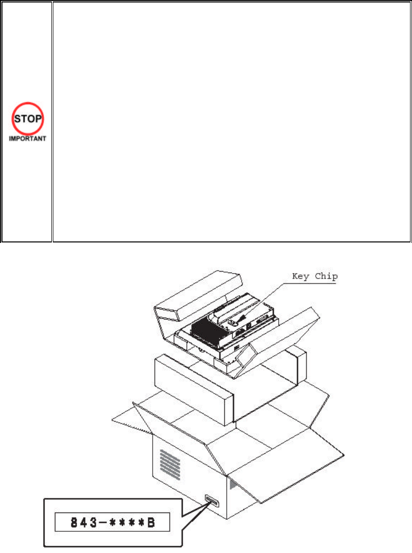
59
3.15.6. Shipping The Media Board
When sending the Media Board for repairs, follow the specifications below and request
repairs or send the Board to your retailer/the repair centre.
Not following the specifications may result in the board not being accepted or in extra
charges being made. Also, mistaken handling can damage or result in loss of parts.
• Be sure to use the special purpose carton box included with this product.
• Do not remove the Key Chip. Send the board with the Key Chip attached.
• Undo the 10 screws holding the Media Board to the Main Board and pack the
Media Board. Do not carry out any disassembly or part removal other than that
specified in this manual.
• Pack the Media Board in the special purpose carton box as shown in the
explanatory diagram.
• The packing material in the carton box has a shock absorbing function. Be sure to
use it when packing. Do not bend or fold the material in a direction other than that
shown on the diagram.
• Do not pack any wires, cables, or screws together with the Board.
• Be sure to attach the special purpose carton box accessory sticker
"843-ããããB."
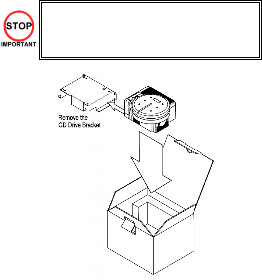
60
3.15.7.Shipping The GD-ROM Drive
• When returning the GD-ROM DRIVE for repair or replacement, be sure to package
it in the original card transit box - THERE ARE NO USER-SERVICEABLE PARTS
INSIDE.
• Ensure the GD-ROM Disk is removed and the GD-ROM Drive Lid is replaced on the
unit, with fixing screw, before packaging. Also, remove the GD-ROM Drive Bracket
and store with the four screws for reuse.
• Failure to return the GD-ROM DRIVE in this manner may invalidate the warranty.
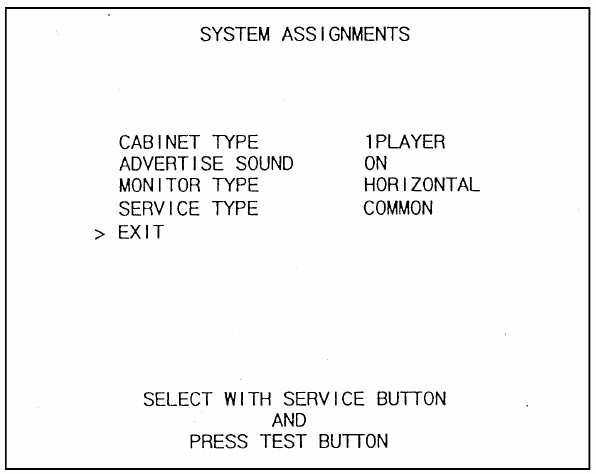
61
3.15.8.Machine Set Up
During linked play, if the test mode is not finished within three minutes on all linked machines, the NETWORK
CHECK cannot be performed, causing a NETWORK ERROR.
First, set up each linked machine to meet the requirements of communication play. If the settings are
incorrect, communication play is not possible.
62
3.15.8.1.Network Play
Up to 4 machines can be linked for network play. Properly connected network cables and correct network play
settings are required for network play.
3.15.8.1.1.Precautions Regarding Network Play Setup
• Before starting to work, ensure that the Power SW is OFF. Failure to observe this
can cause electric shock or short circuit.
• Use care so as not to damage wirings. Damaged wiring can cause electric shock or
short circuit.
• Do not touch undesignated places. Touching places not designated can cause
electric shock or short circuit.
• This work should be performed by the site maintenance individual or other skilled
professional. Performing work by non-technical personnel can cause electric shock
hazard.
• When linking a number of machines, be sure to supply sufficient power for the
corresponding number of machines. Be sure to secure per machine current as stated
in this manual. Failure to observe this can cause a fire and an electric shock
accident.
• Due to the length of the network cable, the distance in between the machines is
limited. However, to avoid accidents, be sure to secure space in excess of 70 cm
between the machines.
• To perform work safely and avoid serious accident such as the cabinet's falling down,
do not perform work in places where step-like grade differences, a ditch, or slope
exist.
• To perform work safely, be sure to secure the space corresponding to number of
machines to be linked. Failure to observe this can cause accident.
• To avoid accidents, use a cable cover that will not cause patrons to trip when laying
network cables in areas of heavy foot traffic.
• To prevent accidents and acts of vandalism, cover the network cables with the
strongest cover possible.
• Network play is not possible between game machines with different cabinet types.
When connecting several games machines together, make sure that a sufficient amount of electrical power is
available for each machine. Plan on providing 15A for each machine in 100-120V locations, and 7A in 220-
240V locations.
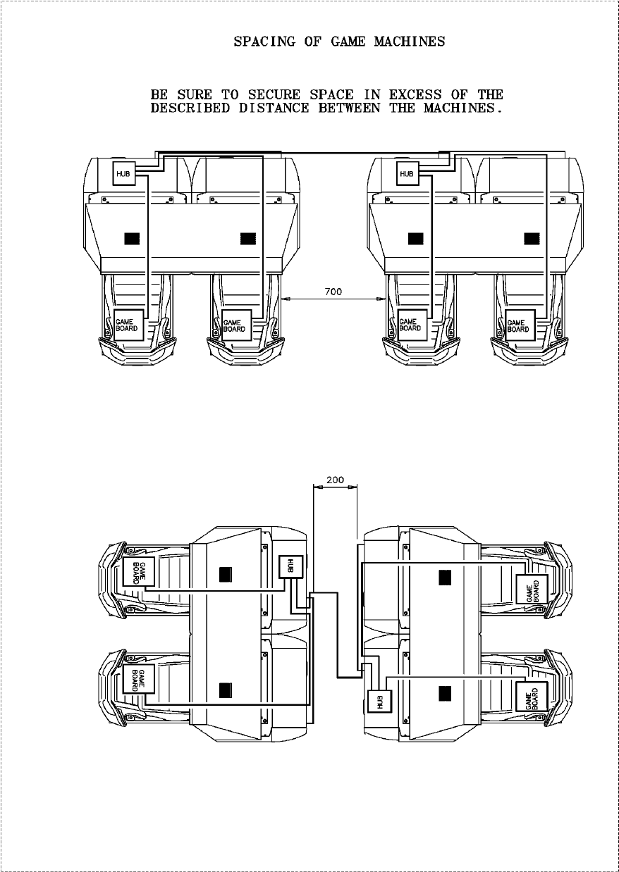
63
3.15.8.1.1.1.Spacing of Game Machines
Leave at least 70 cm of space between game machines.
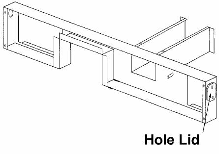
64
3.15.8.1.2.Connecting Network Cables
To enable network play, the hubs inside each of the game machines involved must be connected with network
(LAN) cables. Connect the hub inside one of the machines to the hub in the other machine using LAN cables.
There is no need to connect the other machines to each other in any other way.
Do not connect LAN cables between twin machines when they are not used for network play.
1. Turn off the power and unplug the power cord from the outlet. Place the power cord so as not to
damage it while working.
2. Using the illustration on the previous as reference, move the machines so that they are lined up.
Leave enough space on the front lid side of the machine to perform the rest of the operations in this
procedure.
3. Remove the lower back lids of machines denoted ‘L’ on back.
4. Remove the front covers on both machines.
5. Take off the required hole lids at the ends of the AC covers (see diagram above).
6. Route a spare LAN cable through both machines connecting both hubs.
Any of the ports 2 or above can be used to connect to any of the other gam e machines.
7. Replace all lids and covers.
8. Once the machines have been linked for network play, line them up. Leave as much space as
possible between the machines.
9. Secure all adjustors on each machine. (See Section 3.7.3)
10. Connect the power cord and grounding wire for each machine. (See 3.7.8)

65
3.15.8.1.3.Network Play Settings
Each of the linked machines must be set up for network play. If the machines are not set up correctly,
network play will not be possible.
3.15.8.1.3.1.How To Set Up A Machine For Network Play
1. Turn off the power on each machine to be used in network play.
2. Enter Test mode on each machine. (See Section 5.1)
3. Select GAME TEST MODE and press the TEST Button. The machine will enter Game Test mode and
the screen will display the Game Test menu. (See Section 5.3)
4. Select NETWORK SETTINGS from the Game Test menu and press the TEST Button. The Network
Settings screen will appear. Network settings are carried out on this screen.
5. Set the LINK NUM setting on the Network Settings screen to the number of game machines linked for
network play.
6. Set up the GROUP setting on the Network Settings screen. The GROUP setting is used to divide the
machines linked for network play into groups. For example, a network of 4 machines could be divided
into 2 groups of 2 machines.
7. Set the NUMBER setting on the Network Settings screen so that each machine within a group has a
different number. Make sure that one machine in each group is set to "1".
8. Exit Test mode on each machine. Be sure to choose EXIT from the System Test Menu to exit Test
mode properly.
9. Once each machine has exited Test mode and gone through initialization, it will begin a network test.
During the network test, the monitor will display a network test screen.
10. If there are no problems with network play settings or cable connections, the machine will enter
Advertising mode.
11. If the advertising screen appears after the network test is finished, network settings are complete.
12. The network test should last roughly 20 to 30 seconds. If the network test screen fails to disappear,
the problem is most likely due to one of the following: incorrect settings, an improperly connected
LAN cable, a faulty LAN cable connection, or a severed wire.
NETWORK SETTING
LINK NUM 2(2•`4)
GROUP A(A•`Z)
NUMBER 2(1•`4)
-> EXIT
SELECT WITH SERVICE BUTTON
AND PRESS TEST BUTTON

66
3.15.8.1.4.General Precautions Regarding Network Play
• When setting up machines for network play, settings such as the game's difficulty level
will be derived from the machine whose "NUMBER" is set to "1". If settings on machine
"1" are changed, the other machines will have their settings changed accordingly. On
machines other than "1", settings derived from machine "1" will not be displayed on
screen and cannot be changed.
• Should a network connection fail during network play, gameplay will be suspended and
the Network Error Screen will be displayed.
• If one of the units attached for network play enters Test Mode, the other unit will display
the same Test Mode Screen.
• Even when units are connected for network play, each seat, each game may be given
different cost settings. Incorrect cost settings may cause budget balancing problems.
Note that when 2 or more machines are linked together for network play, some functions are different than for
stand-alone machines.
Whenever Test mode is used on a machine linked for network play, all machines connected to the network
will display the network test screen. When patrons are engaged in network play, do not enter Test mode on
any of the machines in the network, even if the machine is not in use.
However, machines whose GROUP setting is different from that of the machine entering Test mode will not be
affected.
67
3.16. Periodic Check and Inspection
The items listed below require periodic check and maintenance to retain the performance of the machine and
ensure safe operation:
• Be sure to check annually to see if the power cords are damaged. The plug is
securely inserted and that there is no dust in the interior of the machine or between
the socket and the power cord. Using the product in an unclean condition may
cause a fire or electric shock.
• Periodic checks should only be carried out by QUALIFIED SERVICE
PERSONNEL.
DESCRIPTION WHAT TO CHECK INTERVAL
HANDLE MECHA Check the V.R. value
Check adjust gear engagement
Greasing of gears
Monthly
Every 3 months
Every 3 months
ACCELERATOR & BRAKE Check the V.R. value
Check adjust gear engagement
Greasing of gears
Monthly
Every 3 months
Every 3 months
SHIFT LEVER Check SW
Greasing
Monthly
Every 3 months
MONITOR / PROJECTOR Clean screen (do not use water jet)
Check adjustment
Weekly
Monthly
SEAT Rail greasing Monthly
GAME BD Memory Test
Game Assignments
Monthly
Monthly
INTERIOR Clean (do not use water jet) Annually
POWER SUPPLY CORD Check condition Annually
CABINET SURFACE Clean (do not use water jet) As required
CONTROL PANEL Lamp operation
Check switch operation
Monthly
Monthly
COIN MECHANISM Check SW (If Fitted) Monthly

68
4. HOW TO PLAY
4.1. Basic Controls
Insert a coin and press the Start / Credit Button to begin a game.
Choose your car, background music, and other options. View choices with the Steering Wheel, and enter your
selection with the Gas pedal.
During game play, use the Gas pedal to accelerate your car, and the Brake pedal to stop.
The Gear Shifter can be used to shift up and shift down when using Manual transmission.
You can switch between three different view settings with the View Change Button.
4.2. Game Outline
This is a driving game.
The player controls a car (Ferrari), listening to great music and enjoying roadside scenery in the company of a
gorgeous female passenger, all while racing towards the goal before time is up.
The time limit is extended at each checkpoint.
The game ends when the player runs out of time or reaches the goal.
Each game stage ends with a fork in the road where the player must decide the route using the car during the
race. There are a total of fifteen stages, and five separate goal areas.
The three single player game modes are OutRun Mode, Heart Attack Mode, and Time Attack Mode.
The game’s Versus Mode accommodates play for up to four players.
Route Guide with Stage Names
5A
Tulip Garden
4A
Cloudy Highland
3A
Castle Wall 5B
Metropolis
2
A
Deep Lake
4B Industrial Complex
1
A
Palm Beach 3B
Coniferous
Forest
5C
Ancient Ruins
2B
Alpine 4C Snow Mountain
3C
Desert 5D
Imperial Avenue
4D Ghost Forest
5E Cape Way
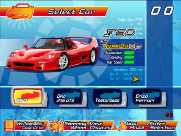
69
4.3. Game Flow
4.3.1. Versus Mode Entry
After inserting coins and pressing the Start Button, Versus Mode Entry prompts will be displayed for potential
players at other game cabinets. Pressing the Start Button within the Versus Mode Entry period will start
Versus Mode.
Closing Versus Mode Entry
To close Versus Mode entry, press the View Change Button and the Brake pedal at the same time before
other players join. (Press the Brake pedal while holding down the View Change Button.)
Versus Mode entry time can also be run down to 0 by holding the Start Button, thus closing Versus Mode
entry.
By closing Versus Mode entry in either of the above ways, the Single Player mode will commence, provided
no players have already joined.
4.3.2. Car Selection
You can select the car model. In Single Player mode you can also change the car colour. Press the Brake
pedal and Shifter together to change the car colour. (Press up or down on the shifter while holding down the
Brake pedal.) These instructions will not be displayed on the screen.
Moving the Shifter up or down while holding down the Brake pedal will bring up a two-character car colour code
just above the ‘Gas Pedal: Enter Selection’ indicator in the lower right corner of the screen. The colour codes
are represented as follows: RE:red, YE:yellow, BK:black, WH:white, SL:silver, GR:green, LB:light blue,
BU:blue.

70
Changing the car model in the middle of colour selection will automatically return the colour to the selected
model’s default colour, after which model and colour selection will again be possible.
The selected car will then be displayed in the chosen colour at the start of the game.
The available colours vary from car to car. The colours available for each car are indicated by a ‘Yes’ in the
chart below, and likewise, only these colours will be shown during selection.
Colour Chart
Car Type Black
Blue Green
Light Blue
Red Silve
r Whit
e Yellow
F50 Yes Yes Yes Yes Yes Yes Yes Yes
360 Spider Yes Yes Yes Yes Yes Yes Yes Yes
Dino 246 GTS Yes No No Yes Yes Yes Yes Yes
365 GTS/4 Daytona Yes No No Yes Yes Yes Yes Yes
Testarossa Yes No No No Yes Yes No Yes
288 GTO Yes No No Yes Yes No Yes Yes
Enzo Ferrari Yes No No No Yes Yes No Yes
F40 Yes Yes Yes Yes Yes Yes Yes Yes
Player-selectable cars and their characteristics are shown below.
The colour shown in parenthesis is the default colour.
F50 (RE), 360 Spider (RE)
(For INTERMEDIATE Player)
Acceleration :******
Handling :********
Top Speed :********
Dino 246 GTS (YE), 365 GTS/4 Daytona (BK)
(For NOVICE Player)
Acceleration :********
Handling :********
Top Speed :******
Testarossa (RE), 288 GTO (RE)
(For INTERMEDIATE Player)
Acceleration :***********
Handling :******
Top Speed :******
Enzo Ferrari (RE), F40 (RE)
(For PROFESSIONAL Player)
Acceleration :******
Handling :*****
Top Speed :***********
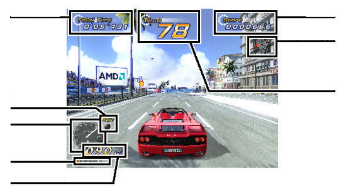
71
4.3.3. Transmission Selection
You can choose between Automatic transmission and Manual transmission.
When Manual transmission is selected, the number of gears varies with the car model.
• 6-speed: F50, 360 Spider, Enzo Ferrari
• 5-speed: Dino 246 GTS, 365 GTS/4 Daytona, Testarossa, 288 GTO, F40
4.3.4. Mode Selection
In Single Player, you will choose a game mode.
4.3.4.1.OutRun Mode
1) Total Time
2) Time Counter
3) Score
4) Route Map
5) Tachometer
6) Shift Up Indicator
7) Speed Meter
8) Shift Indicator
This is the pure driving mode, enjoyed with a young lady by your side.
You select branching paths and try to reach the goal within the time limit.
The game ending varies depending on which goal is reached.
‚
„
ƒ
‡
ˆ
…
†
•
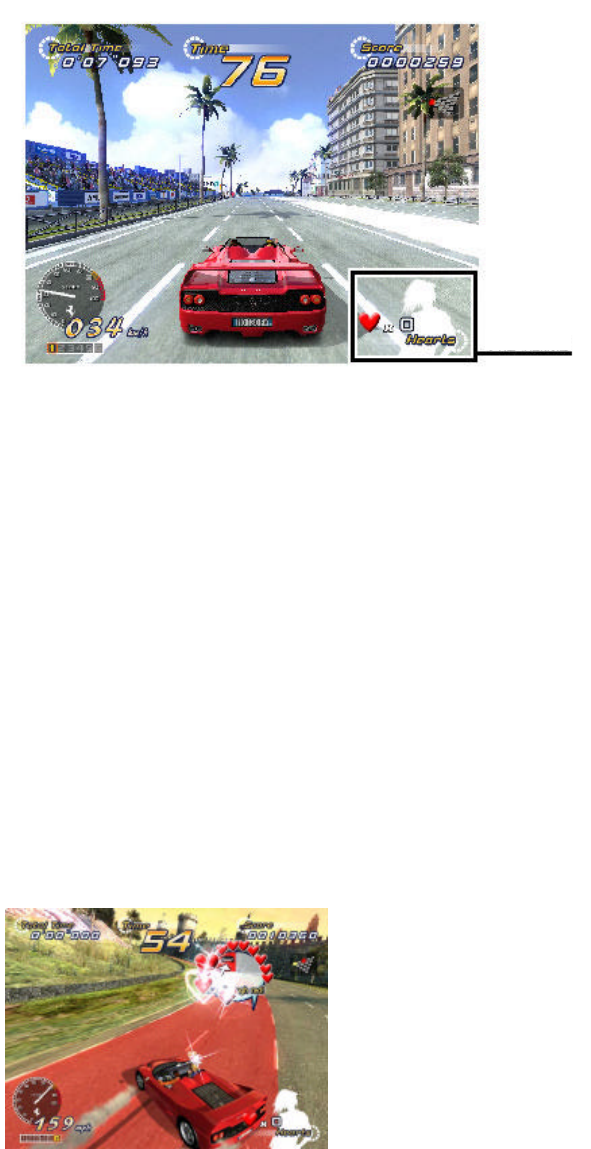
72
4.3.4.2.Heart Attack Mode
1) Lady’s Heart Meter
This is the mode where you raise the Lady’s Heart Meter by fulfilling her requests.
Collect as many of the hearts showing her feelings as possible.
You must pursue her request for the duration of the indicated track section.
The Lady’s Requests
• ’Drift more!’
Try drifting continuously throughout the track section.
• ’Keep passing cars!’
Pass as many cars as possible throughout the track section.
• ’Don’t crash!’
Avoid hitting any other cars, walls, or obstacles throughout the track section.
• ’Run through red/blue!’
Drive on the indicated colour section of the roadway.
•

73
• ’Hit the blue cones!’
There are twenty blue cones placed on the roadway—try to hit as many as you can.
• ’Cut the line!’
Drive through the yellow heart lines between cars on the roadway. Lines cut once will not come back.
• ’Catch the Heart!’
There are Hearts floating around on the roadway. Try your best to drive through the Hearts. Hearts
collected once will not come back.
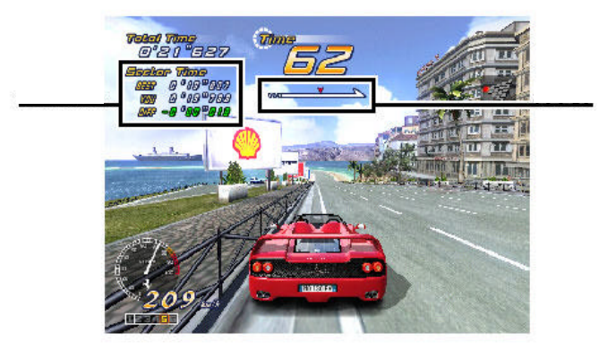
74
Special Requests
Satisfying certain conditions will open up Special Requests.
Ending
The game ending will change depending on your performance assessment.
4.3.4.3.Time Attack Mode
1) Sector Time
2) Position
This mode is a test of time in reaching the goal.
Player driving data is recorded for goal time, route best time, and slowest time. The player can then compete
against his own time in subsequent plays.
When there is no player data recorded, a default data car will appear.
Ending
The game ending will change depending on your goal time.
Internet Ranking Password
If your time qualifies, you’ll be given an Internet Ranking password. Using this password, you can participate
in the Internet Ranking system.
Goal Choice
You can choose from five different destination goal points.
(This option is only available in the Time Attack Mode.)
Route Choice
After choosing a goal, you can decide on a specific route for that particular goal.
•
‚
75
(This option is only available in the Time Attack Mode.)
There is one exception, however—Goal A, ‘Tulip Garden’, and Goal E, ‘Cape Way’ each have only one route
so the Route Choice option will not be available.
Goal B, ‘Metropolis’, and Goal D, ‘Imperial Avenue’ each have four possible routes, while Goal C, ‘Ancient
Ruins’ has six possible routes to choose from.
BGM Selection
There are seven different in-game songs to select from. In Versus Mode, each player can listen to his or her
own individual selection.
• SPLASH WAVE (from original OutRun)
• MAGICAL SOUND SHOWER (from original OutRun)
• PASSING BREEZE (from original OutRun)
• Risky Ride (new)
• Shiny World (new)
• Night Flight (new, includes lyrics)
• Life was bore (new, includes lyrics)

76
4.4. Versus Play
4.4.1. Versus Mode Game Play
The car colours for versus mode are fixed for each player. 1P: Red, 2P: Yellow, 3P: White/Silver (depending
on car model), 4P: Black
The position order on the starting grid is determined by the order of Versus Mode entry (decided by who
presses the Start Button first).
The course is decided as the route taken by whoever first reaches a given course branch.
4.4.2. Special Versus Mode Commands
The ‘No Handicap’ and ‘Player Only’ modes are selectable with special commands entered at the game’s
selection screen.
4.4.2.1.No Handicap Mode
In the usual Versus Mode, the player in second place during a race can catch up easier with computer
assistance, but this assistance isn’t available in the No Handicap mode.
To activate No Handicap mode, all participants in the Versus Mode competition must press the Brake pedal
together with the Shifter up. (Push the shifter up while holding down the Brake pedal.) An icon will be
displayed on the right side of the selection screen when this mode is activated.
4.4.2.2.Player Only Mode
In Player Only mode, no cars besides the player-
controlled cars will appear in the race.
To activate Player Only mode, all participants in the
Versus Mode competition must press the Brake
pedal together with the Shifter down. (Push the shifter
down while holding down the Brake pedal.) An icon
will be displayed on the right side of the selection
screen when this mode is activated.

77
4.5. Gameplay Techniques and Secret Commands
4.5.1. How to Drift
After letting go of the Gas pedal, immediately press the Brake pedal. Then, quickly steer sharply into the turn
and press the Gas pedal.
In the case of Manual transmission, shift down one gear just before the turn, then immediately steer sharply
into the turn.
4.5.2. Mid-game Quit Command
You can quit in the middle of a game. This command is only possible in the Single Player mode.
To activate the mid-game quit command, stop the car and press the Brake pedal, View Change button, and
Shifter up. (While holding down the Brake pedal, continue to hold down the View Change button, and finally
press the Shifter up.)
After inputting the command, the player is prompted, ‘Do you really want to quit this game? Yes/No’.
Choosing ‘Yes’ will finish the game, and ‘No’ will return the player to the game.
78
There are three conditions under which this command cannot be executed:
• The player is near the starting grid.
• The remaining time is under 8 seconds.
• ’No’ has already been chosen once.
4.6. Character Introductions
Three major characters appear in the game.
1. Driver
Name: Alberto
Personal Info: Although easy-going on the outside, he’s a real go-getter.
He has a very distinguished driving sense. He’s also quite rich.
2. OutRun Mode Lady
Name: Jennifer
Personal Info: She’s a filthy rich ‘princess’, always selfishly seeking the next thrill. She’s involved with
Alberto, his Ferrari a present from her. She has a sharp eye for driving techniques.
3. Heart Attack Lady
Name: Clarissa
Personal Info: She’s peppy and unmistakably sexy. A driving fan, with a weakness for thrill rides.
She’s very demanding, but her sweet character makes her hard to dislike.
79
5. MAINTENANCE INSTRUCTIONS
5.1. Explanation of Test and Data Display
Use the switches on the VTS to enter the TEST MODE. This will allow you to carry out post installation and
periodic checks and adjustments. The following section details the function of each of the tests:
• Be very careful about entering TEST MODE. If the machine you wish to test is
linked to other machines, exiting test on your machine will cause a network check
to be carried out. This will disable all other machines linked to it.
ITEM DESCRIPTION / REFERENCE INTERVAL
INSTALLATION
OF THE
MACHINE
When the machine is installed perform the following checks:
Check to see that each setting is as per the standard settings input at
the time of shipment.
In the INPUT TEST mode, check each switch and VR. Section 5.3.1
In the OUTPUT TEST mode, check each of the lamps. Section 5.3.2
In the MEMORY TEST mode check all of the IC’s on the IC BD.
Section 5.2.1
Monthly
MEMORY On the TEST MENU screen choosing the MEMORY TEST allows self
test to be performed. In this test RAM & ROM are tested. Monthly
PERIODIC
CHECKS Periodically perform the following
MEMORY TEST. Section 5.2.1.
Ascertain each setting:
In the INPUT TEST mode, test the control devices. Section 5.3.1
In the OUTPUT TEST mode, check each of the lamps. Section 5.3.2
Monthly
CONTROL
SYSTEM In the INPUT TEST mode, check each switch and VR. Section 5.3.1
Adjust or replace each switch and VR. Section 3.9
Monthly
MONITOR In the CRT TEST mode, check to ensure the monitor is adjusted
correctly. Section 5.2.4
Clean screen (switch off machine and remove the plug)
Monthly
Weekly
IC BOARD MEMORY TEST
In the SOUND TEST mode, check the sound related ROMs. 5.2.3
Monthly
DATA CHECK Check such data as held in the bookkeeping screens, relating to
number and length of plays. Section 5.3.5 Monthly
EXTERIOR
MAINTENANCE Clean surfaces
Lubricate seat sliders
Monthly
COIN
MECHANISM Check switch operation (if fitted) Monthly
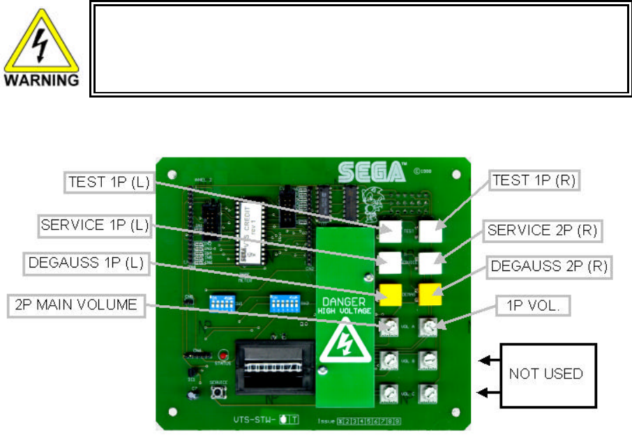
80
5.1.1. VTS Assembly
• Do not touch places other than those specified. Touching places not specified could
cause an electric shock or short circuit.
Opening the Coin Chute door will reveal the VTS Assembly shown above. The function of each switch is as
follows. The controls on the left affect the 1P cockpit, those on the right the 2P
TEST BUTTON
(TEST SW)
Used to enter TEST mode. Also has function
during TEST mode. Refer to the later section
detailing TEST mode.
SERVICE BUTTON
(SERVICE SW)
Gives credits without registering on the coin
counter. Also used during TEST mode.
DEMAG Demagnetises (degausses) the CRT to remove
colour unevenness.
VOLUME MAIN Adjusts the volume of the left and right main
speakers.
VOLUME WOOFER Adjusts the volume of the woofer.
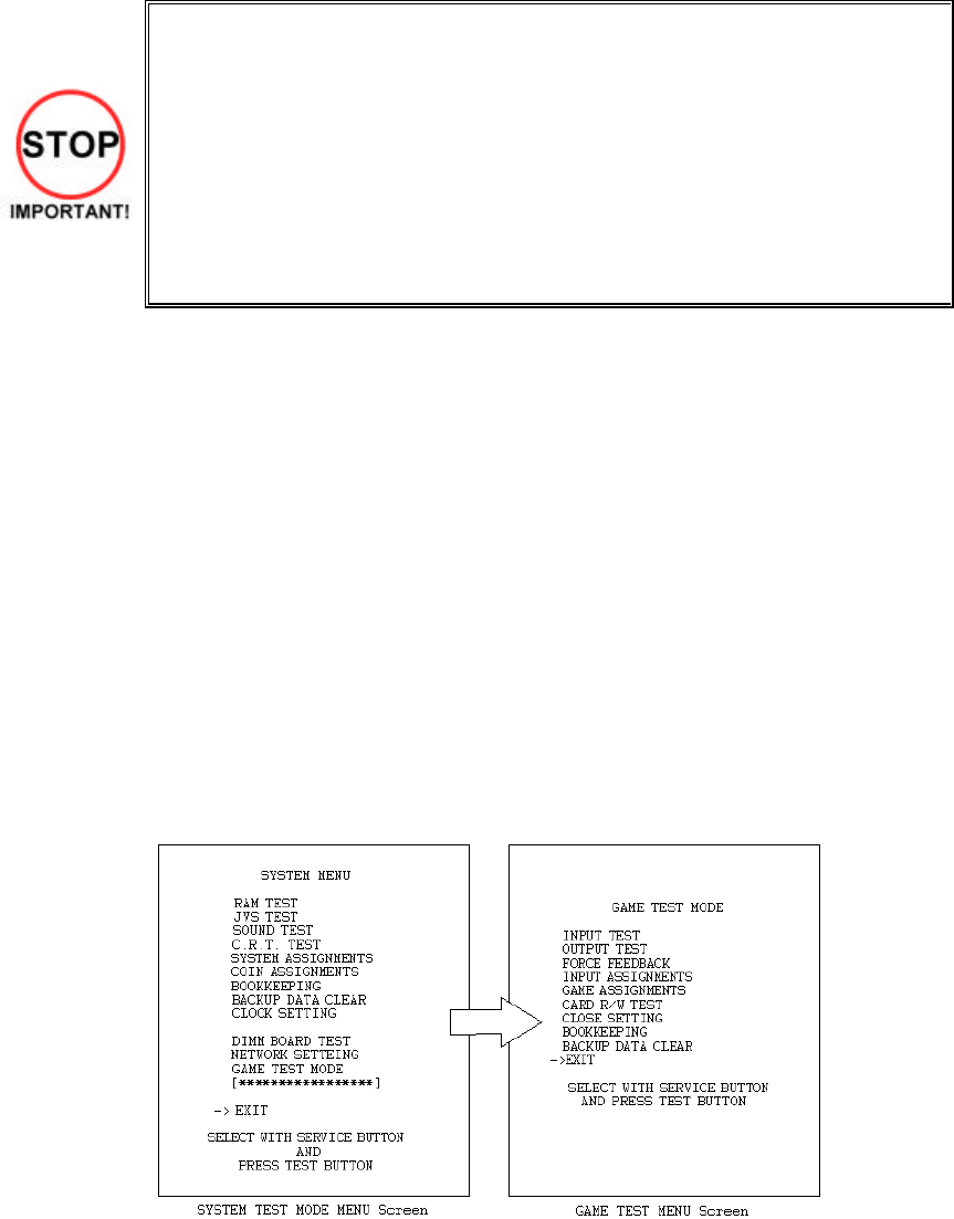
81
5.2. System Test Mode
• The contents of settings changed in the TEST mode are stored when the test
mode is finished from EXIT in the menu mode. If the power is turned off before the
TEST mode is finished, the contents of setting change become ineffective.
• Executing "BACKUP DATA CLEAR" in the SYSTEM TEST MODE does not clear
the BOOKKEEPING data in the GAME TEST mode.
• Entering the TEST mode clears fractional number of coins less than one credit
and BONUS ADDER data.
• Perform setting as per specified in this manual for operation. If setting not
specified is performed for operation, proper function of this product may not be
obtained.
In the SYSTEM TEST MODE, IC BD functioning can be checked, the monitor adjusted, and the coin setting
performed.
Refer to NAOMI NETWORK SYSTEM SERIVCE MANUAL for the details. Note that the setting of the following
items need to be performed in accordance with the instruction given.
CABINET TYPE : 1 PLAYER(S)
MONITOR TYPE : HORIZONTAL
SERVICE TYPE : COMMON
COIN CHUTE TYPE : COMMON
NETWORK TYPE : NONE
The SEQUENCE SETTING items of COIN/CREDIT SETTING are as follows.
SEQUENCE SETTING
SEQUENCE 1: Number of credits required for starting the game.
SEQUENCE 2: Number of credits required for continuing the play.
SEQUENCE 3: Number of credits required for dedicated CARD purchase.
SEQUENCE 4 -8: NOT USED
Press the TEST BUTTON to bring up the screen shown to the left.
Press the SERVICE BUTTON to move downwards through the list. The arrow shows the current selection.
Press the TEST BUTTON to activate the selected test.
To finish TEST MODE, move the arrow to EXIT and press the TEST.
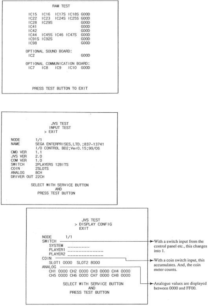
82
5.2.1. RAM Test
The memory test mode is for automatically
checking the on-board memory IC functioning.
“GOOD” is displayed for normal IC’s and “BAD “ for
abnormal IC’s
• When the test is completed, if the results are
as shown on the left then the Game Board is
satisfactory.
• The test should take approximately thirty
seconds to complete. If the test exceeds this
time the board may have malfunctioned.
• After finishing the test press the TEST BUTTON
or START BUTTON to exit.
5.2.2. JVS Test
• In this test, functioning of the I/O Board
connected to the Game Board is displayed, and
INPUT TEST can be performed. Select EXIT to
return to the MENU screen, or select INPUT
TEST to display the second screen.
Select EXIT to return to the MENU screen.
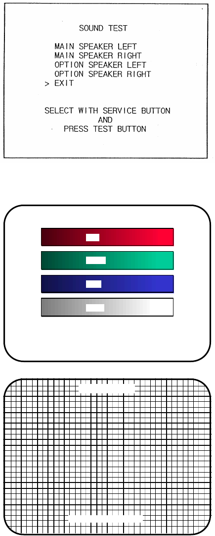
83
5.2.3. Sound Test
Select the sound test to check the status of the amplifiers, soundboards, and speakers.
Press the SERVICE button or view change button to move the arrow to the desired test item.
Press TEST button to output the sound.
• Select the sound source with SERVICE.
• On pressing TEST, the test sound is emitted from
the selected source.
Select EXIT to return to MENU screen.
5.2.4. C.R.T Test
C.R.T TEST
PAGE 1/2
C.R.T. TEST 1/2
PRESS TEST BUTTON TO CONTINUE
RED
GREEN
BLUE
WHITE
Selecting CRT test allows the projector adjustment to
be checked for colour and distortion.
Press the test or start button to have the second CRT
test screen appear.
C.R.T. TEST 2/2
PRESS TEST BUTTON TO EXIT
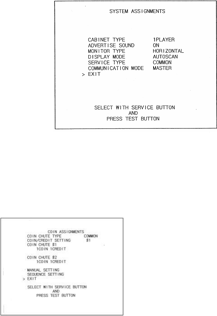
84
5.2.5. System Assignments
Allows system options to be set. Select required setting with SERVICE button, confirm with TEST button.
Default settings are indicated in parentheses.
• CABINET TYPE specifies Control Panel and number of Coin Chutes. The number of players displayed in
BOOKKEEPING varies in accordance with the value displayed here. (1PLAYER)
• ADVERTISE SOUND allows the sound emission to be turned (ON) or OFF during ADVERTISE MODE.
• MONITOR TYPE changes the orientation of the image on the screen (HORIZONTAL)
• SERVICE TYPE sets the functioning of the SERVICE button, should several SERVICE buttons exist.
INDIVIDUAL: Service credit is applied to the machine on which the SERVICE button is pressed.
(COMMON): Service credit is applied to all machines when SERVICE button is pressed.
5.2.5.1.Coin Assignments
Select the coin assignments mode to set the coin
to credit ratios.
This can be any of the pre-set values or can be
done manually.

85
5.2.5.2.Coin/Credit Setting (Coin Chute Common Type)
SETTING FUNCTIONING OF COIN CHUTE #1 FUNCTIONING OF COIN CHUTE #2
SETTING #1 1 COIN 1 CREDIT 1 COIN 1 CREDIT
SETTING #2 1 COIN 2 CREDITS 1 COIN 1 CREDIT
SETTING #3 1 COIN 3 CREDIT 1 COIN 1 CREDIT
SETTING #4 1 COIN 4 CREDITS 1 COIN 1 CREDIT
SETTING #5 1 COIN 5 CREDITS 1 COIN 1 CREDIT
SETTING #6 1 COIN 2 CREDITS 1 COIN 2 CREDITS
SETTING #7 1 COIN 5 CREDITS 1 COIN 2 CREDITS
SETTING #8 1 COIN 3 CREDITS 1 COIN 3 CREDITS
SETTING #9 1 COIN 4 CREDITS 1 COIN 4 CREDITS
SETTING #10 1 COIN 5 CREDITS 1 COIN 5 CREDITS
SETTING #11 1 COIN 6 CREDITS 1 COIN 6 CREDITS
SETTING #12 2 COINS 1 CREDIT 2 COINS 1 CREDIT
SETTING #13 1 COIN 1 CREDIT 2 COINS 1 CREDIT
SETTING #14 1 COIN 2 CREDITS 2 COINS 1 CREDIT
SETTING #15 1 COIN
2 COINS 1 CREDIT
3 CREDITS 1 COIN
2 COINS 1 CREDIT
3 CREDITS
SETTING #16 1 COIN 3 CREDITS 1 COIN
2 COINS 1 CREDIT
3 CREDITS
SETTING #17 3 COINS 1 CREDIT 3 COINS 1 CREDIT
SETTING #18 4 COINS 1 CREDIT 4 COINS 1 CREDIT
SETTING #19 1 COIN
2 COINS
3 COINS
4 COINS
1 CREDIT
2 CREDITS
3 CREDITS
5 CREDITS
1 COIN
2 COINS
3 COINS
4 COINS
1 CREDIT
2 CREDITS
3 CREDITS
5 CREDITS
SETTING #20 1 COIN 5 CREDITS 1 COIN
2 COINS
3 COINS
4 COINS
1 CREDIT
2 CREDITS
3 CREDITS
5 CREDITS
SETTING #21 5 COINS 1 CREDIT 5 COINS 1 CREDIT
SETTING #22 1 COIN 2 CREDITS 3 COINS
5 COINS 1 CREDIT
2 CREDITS
SETTING #23 2 COINS
4 COINS
5 COINS
1 CREDIT
2 CREDITS
3 CREDITS
2 COINS
4 COINS
5 COINS
1 CREDIT
2 CREDITS
3 CREDITS
SETTING #24 1 COIN 3 CREDITS 2 COINS
4 COINS
5 COINS
1 CREDIT
2 CREDITS
3 CREDITS
SETTING #25 1 COIN
2 COINS
3 COINS
4 COINS
5 COINS
1 CREDIT
2 CREDITS
3 CREDITS
4 CREDITS
6 CREDITS
1 COIN
2 COINS
3 COINS
4 COINS
5 COINS
1 CREDIT
2 CREDITS
3 CREDITS
4 CREDITS
6 CREDITS
SETTING #26 1 COIN 6 CREDITS 1 COIN
2 COINS
3 COINS
4 COINS
5 COINS
1 CREDIT
2 CREDITS
3 CREDITS
4 CREDITS
6 CREDITS
SETTING #27 FREE PLAY FREE PLAY

86
5.2.5.3.Coin/Credit Setting (Coin Chute Individual Type)
SETTING FUNCTIONING OF COIN CHUTE #1
SETTING #1 1 COIN 1 CREDIT
SETTING #6 1 COIN 2 CREDITS
SETTING #8 1 COIN 3 CREDITS
SETTING #9 1 COIN 4 CREDITS
SETTING #10 1 COIN 5 CREDITS
SETTING #11 1 COIN 6 CREDITS
SETTING #12 2 COINS 1 CREDIT
SETTING #15 1 COIN
2 COINS 1 CREDIT
3 CREDITS
SETTING #17 3 COINS 1 CREDIT
SETTING #18 4 COINS 1 CREDIT
SETTING #19 1 COIN
2 COINS
3 COIN S
4 COINS
1 CREDIT
2 CREDITS
3 CREDITS
5 CREDITS
SETTING #21 5 COINS 1 CREDIT
SETTING #22 3 COINS
5 COINS 1 CREDITS
2 CREDITS
SETTING #23 2 COINS
4 COINS
5 COINS
1 CREDIT
2 CREDITS
3 CREDITS
SETTING #25 1 COIN
2 COINS
3 COINS
4 COINS
5 COINS
1 CREDIT
2 CREDITS
3 CREDITS
4 CREDITS
6 CREDITS
SETTING #27 FREE PLAY
87
5.2.5.4.Manual Setting
Select manual setting to manually set the coin to
credit ratios.
The available combinations are detailed below.
MANUAL SETTING
COIN TO CREDIT 1 COIN 1 CREDIT
2 COINS 1 CREDIT
3 COINS 1 CREDIT
4 COINS 1 CREDIT
5 COINS 1 CREDIT
6 COINS 1 CREDIT
7 COINS 1 CREDIT
8 COINS 1 CREDIT
9 COINS 1 CREDIT
BONUS ADDER NO BONUS ADDER
2 COINS GIVE 1 EXTRA COIN
3 COINS GIVE 1 EXTRA COIN
4 COINS GIVE 1 EXTRA COIN
5 COINS GIVE 1 EXTRA COIN
6 COINS GIVE 1 EXTRA COIN
7 COINS GIVE 1 EXTRA COIN
8 COINS GIVE 1 EXTRA COIN
9 COINS GIVE 1 EXTRA COIN
COIN CHUTE MULTIPLIER 1 COIN COUNTS AS 1 COIN
1 COIN COUNTS AS 2 COINS
1 COIN COUNTS AS 3 COINS
1 COIN COUNTS AS 4 COINS
1 COIN COUNTS AS 5 COINS
1 COIN COUNTS AS 6 COINS
1 COIN COUNTS AS 7 COINS
1 COIN COUNTS AS 8 COINS
1 COIN COUNTS AS 9 COINS
88
5.2.5.5.Sequence Setting
Selecting SEQUENCE SETTING allows the number of credits required to start the game to be set. Each
sequence can be set between 1 and 5. Select EXIT to return to the first screen.
89
5.2.5.6. Bookkeeping
This mode consists of 2 pages that allow the data
relating to credit and game play time to be checked.
In page 1 mode press SERVICE to proceed to page
2, in page 2 mode press TEST to return to the test
menu.
• Total time is displayed as XXH XXM XXS and no
date will be displayed after exceeding 24 hours.
• The displays for number of coin and number of
service vary depending on the CABINET TYPE set
in SYSTEM ASSIGNMENTS. Number of credit
displays 1 if COIN CHUTE TYPE is set to
COMMON in COIN ASSIGNMENTS. If COIN
CHUTE TYPE is set to INDIVIDUAL, the
applicable number in CABINET TYPE setting will
be displayed.
• On the second screen, each sequence displays
the frequency of functioning.
5.2.5.7.Backup Data Clear
Clears the contents of bookkeeping. When clearing,
bring the arrow to “YES (CLEAR)” and press the test
button. When the data has been cleared
“COMPLETED” will be displayed. Bring the arrow to
“NO (CANCEL)” and press the test button to return to
the menu mode.
Note that this does not clear the contents of
BOOKKEEPING in GAME TEST MODE. For this,
use the BACKUP DATA CLEAR in GAME TEST
MODE.
90
5.2.5.8.ROM BD Test
In this test, Game Board ROM is checked. If GOOD is displayed, it is satisfactory. The IC number, TYPE,
BYTE and WORD refer to the checksum of each unit. Press TEST to exit.
On above screen, IC35 and IC36 (program ROMs) do not display GOOD or BAD. Press TEST Button to EXIT.
5.2.5.9. Clock Setting
YEAR, MONTH, DAY, HOUR and MINUTE are set for SEGA NAOMI BOARD. Select the desired item with
SERVICE button and press TEST to increase the value. Select EXIT to return to MENU mode.
91
5.3. Game Test Mode
[IMPORTANT]
When changing the game configuration, changes will not be enabled until the Game Test Mode has
been completed. Be sure to exit the Game Test Mode properly after configuration changes.
Select GAME TEST MODE from the System Menu screen to display the Game Test Menu screen as follows.
Use the SERVICE Button to move the cursor to the desired test item. Press the TEST Button to enter the
selected item.
NOTE: In Upright cabinet types, the DRIVE BOARD TEST is not necessary and the option will not be
displayed.
After selecting an item, read the explanations below regarding operation.
After the test is complete, move the cursor to EXIT and press the TEST Button to return to the System Menu
screen.
92
5.3.1. Input Test
Select INPUT TEST to display the following screen and check the status of input devices.
This test should be used periodically to check that each input device is functioning correctly.
Test the STEERING, GAS (ACCEL) and BRAKE controls to ensure that they are func tioning properly and that
the parameters change smoothly as each input device is operated.
Display N, UP and DOWN using the GEAR POSITION. N displays that there is no control input. Verify that
both UP and DOWN display in sync with the position of the shift knob.
Press the START, CHANGE VIEW, SERVICE and TEST Buttons. If functioning correctly, each indicator will
switch from OFF to ON.
Press the SERVICE and TEST Buttons simultaneously to return to the Game Test Menu screen.
93
5.3.2. Output Test
Select OUTPUT TEST to display the following screen and check the status of each lamp.
This test should be used periodically to check that the lamps are functioning correctly.
On this screen the cursor will switch automatically between items, lighting up the respective lamps.
• START BUTTON : Lights up the START button.
• VIEW CHANGE BUTTON: Lights up the View Change button.
Press the TEST Button to return to the Game Test Menu screen.
94
5.3.3. Drive Board Test
Select DRIVE BOARD TEST to display the following screen and check the status of steering motor.
Use the SERVICE Button to select the desired test item. Press the TEST Button to activate the selected
item.
NOTE: This test will not be displayed in Upright cabinet types.
• STOP MOTOR: Halts motor activity.
• ROLL RIGHT: Rotates steering wheel completely to the right.
• ROLL LEFT: Rotates steering wheel completely to the left.
• CENTER OF STEER: Steering wheel motor’s center of control is displayed.
RIGHT: Moves center of control position to the right.
LEFT: Moves center of control position to the left.
• MOTOR POWER: Sets the steering resistance.
There are four levels to choose from, 100% (strong resistance), 90%,
80%, and 60% (weak resistance). (80% is the default setting)
After changing the settings, select EXIT and press the TEST Button to return to the Game Test Menu screen.
95
5.3.4. Game Assignments
Select GAME ASSIGNMENTS to display the current game settings and make changes.
Changes to settings are not enabled until Test Mode is exited. After changing settings, be sure to exit Test
Mode.
NOTE: When adjusting network play settings, DIFFICULTY, ADVERTISE SOUND, LANGUAGE,
SPEEDOMETER, and QUICK START items will be decided by the cabinet with LINK_ID “1”. Changes made
to the game display or settings during game play do not affect the Game Test Menu settings.
Perform the following settings for each item.
? DIFFICULTY: The game difficulty setting. There are 5 difficulty levels with VERY EASY being the easiest
setting and VERY HARD being the most difficult setting. (Default Setting: NORMAL)
? CABINET TYPE: The game cabinet type setting. Choose from either STANDARD or UPRIGHT.
? ADVERTISE SOUND: The setting to turn the advertising sound ON/OFF. (Default Setting: ON)
? LANGUAGE: The game language setting. Choose from either JAPANESE or ENGLISH. (With JAPAN as
the Country Setting, the default LANGUAGE setting is JAPANESE. ENGLISH is set as the default for a
Country Setting of USA or EXPORT.)
? SPEEDOMETER: The speed display setting. During game play, KILO will be displayed as “km/h”, and
MILE as “mph”. Choose one of these options. (With JAPAN or EXPORT as the Country Setting, the default
SPEEDOMETER setting is KILO (km/h). MILE (mph) is set as the default for a Country Setting of USA.)
? QUICK START: Choose OFF or ON. The ON setting takes the player directly to the game selection screen
after entering credits into the machine. (Default Setting: OFF)
? LINK_ID: The setting which determines the Player Number of each cabinet. It assigns unique numbers for
cabinets in a single group. Do not assign two or more cabinets the same number. For network play, it is
necessary to complete the LINK_ID, TOTAL MACHINE, and GROUP settings for each cabinet. (Default
Setting: 1, Maximum: 4)
96
? TOTAL MACHINE : The number of network connected game cabinets. (Sets the number of competing
cabinets in Versus Mode.) Setting this to “1” limits possible play modes to Single Player mode only. (Default
Setting: 1, Maximum: 4)
? GROUP: Used for dividing networked cabinets into groups. For example, to split up a group of four
networked machines into two groups of two cabinets, set two cabinets to “1” and the other two cabinets to “2”.
Generally, setting all cabinets to “1” is recommended.
After changing the settings, select EXIT and press the TEST Button to return to the Game Test Menu screen.
<Network Versus Mode Cabinet Settings>
Cases for four cabinets (A, B, C, and D) connected via network cable.
4-Cabinet Versus
CABINET A B C D
LINK_ID 1 2 3 4
TOTAL MACHINE 4 4 4 4
GROUP 1 1 1 1
Status Four cabinets can compete.
3-Cabinet Versus
CABINET A B C D
LINK_ID 1 1 2 3
TOTAL MACHINE 1 3 3 3
GROUP 1 2 2 2
Status Single play only. Three cabinets can compete.
2-Cabinet Versus
CABINET A B C D
LINK_ID 1 2 1 2
TOTAL MACHINE 2 2 2 2
GROUP 1 1 2 2
Status Two cabinets can compete. Two cabinets can compete.
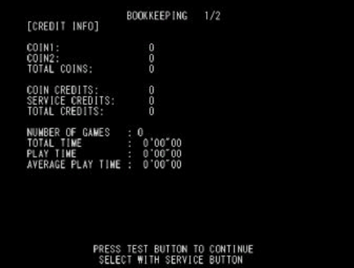
97
5.3.5. Bookkeeping
Selecting BOOKKEEPING will display the following screen. All up-to-date operation data will be displayed on
two BOOKKEEPING screens.
Use the TEST Button to cycle between the first screen (BOOKKEEPING 1/2) and the second screen
(BOOKKEEPING 2/2).
? COIN CHUTE #1: The number of coins inserted into Coin Slot 1.
? COIN CHUTE #2: The number of coins inserted into Coin Slot 2.
? TOTAL COINS: The total number of coins inserted into the coin slots.
? COIN CREDITS: The number of credits for the coins inserted.
? SERVICE CREDITS: The number of credits input by the SERVICE Button.
? TOTAL CREDITS: Total credits from coins and the SERVICE Button.
? NUMBER OF GAMES: The total number of games played.
? TOTAL TIME: The amount of time the unit has been in operation.
? PLAY TIME: Total playing time.
? AVERAGE PLAY TIME: Total play time divided by the total number of games played.
Press the TEST Button to move to screen 2/2 of BOOKKEEPING.
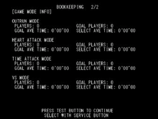
98
This shows the number of plays and the respective play times. This histogram should be referred to when
setting the Game Difficulty.
Press the TEST Button to return to the Game Test Menu screen.
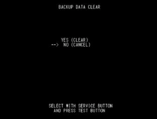
99
5.3.6. Backup Data Clear
Select BACKUP DATA CLEAR to clear the contents of BOOKKEEPING, ranking data and coin/credit data.
To clear data, use the SERVICE Button to move the cursor to YES (CLEAR) and then press the TEST Button.
When the data has been cleared, the message “COMPLETED” will be displayed.
Press the TEST Button again to return to the Game Test Menu screen.
Move the cursor to NO (CANCEL) and press the TEST Button to return to the Game Test Menu screen
without clearing the data.
Note that this operation does not affect GAME ASSIGNMENTS or GUN ADJUSTMENT settings.
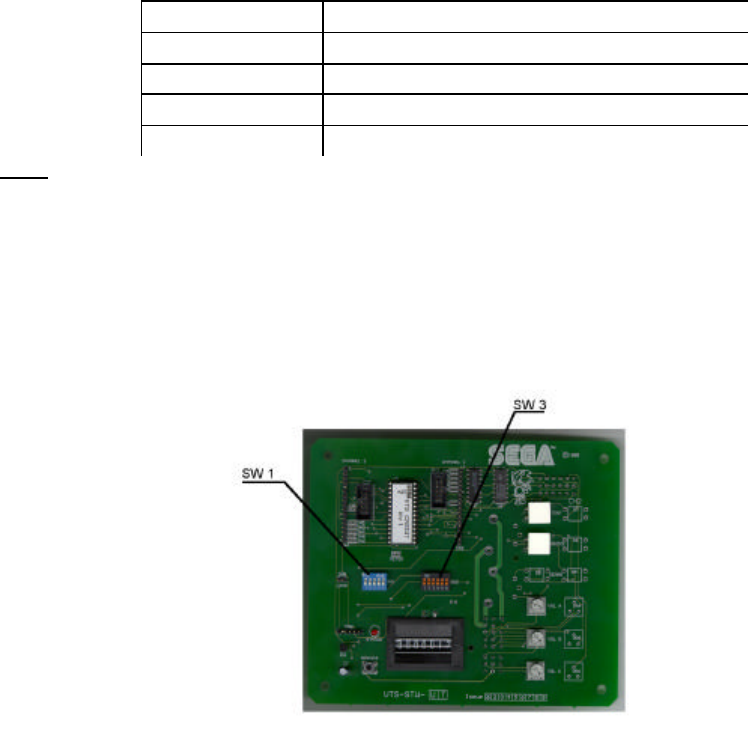
100
6. COIN MECH INSTALLATION AND CREDIT BOARD SET UP
6.1. Introduction
Game credits between the Coin Mechanism and the game board for this machine are controlled by a VTS
board. This electronic circuit allows the price of play to be set for a range of different countries. These
functions are set on Dual In Line (DIL) PCB mounted switches.
SW1 is used to set the currency (or coin ratio) and SW3 the price of play. Refer to the Tables on the following
pages for the correct settings for your environment.
The VTS board pictured below is mounted in the Coin Chute Tower.
The VTS board is connected to the coin validator and lamps via a dedicated wiring harness depending upon
the coin validator used:
Wiring Harness Validator
LM1006 Coin Controls (15 way connector)
LM1007 Mars (13 way connector)
LM1008 Mechanical See note 2
N/A NRI See note 1
Notes
1. If NRI mechanisms are to be used, these should be ordered with the highest denomination coin on coin
path #1 and the lowest denomination on coin path #4. The VTS board should be then be set up for either
the UK or Switzerland settings. A minimum connecting lead length of 600mm is required.
2. Mechanical coin mechanisms may be connected in parallel allowing two identical mechanisms to be fitted.
The VTS Board
101
Credit Board Mode Settings Switch 3
Country
Setting Switch 3 Setting Coin Validator Programming C120/SR3 Only
SW1
SW2
SW3
SW4
SW5
SW6
COIN1
COIN2
COIN3 COIN4 COIN5 COIN6
COIN7
COIN8 COIN9
COIN10
COIN11
COIN12
UK Coin Controls
C220 Parallel
OFF
OFF
OFF
OFF
£1 50p new
20p 10p - 50p old
- -
UK Coin Controls
C220 Binary ON OFF
OFF
OFF
£1 50p new
20p 10p - 50p old
- £2
UK Coin Controls
C220 Binary OFF
ON OFF
OFF
£1 50p new
20p 10p - £2 - 50p
old
UK Coin Controls
SR3 Parallel ON ON OFF
OFF
£1 50p new
20p 10p - £2 - 50p
old
- - - -
UK
Euro
Coin Controls
SR3 Parallel OFF
OFF
ON OFF
£2
€2
£1
€1
50p new
50¢
20p
20¢
10p
10¢
- - - 50p old
- - -
UK Mars ME/MS
111 Parallel ON OFF
ON OFF
£1 £2 20p 10p 50p new
50p old
UK NRI Parallel OFF
ON ON OFF
10p 20p 50p £1 £2 -
Belgium
Parallel ON ON ON OFF
- 50BFr 20BFr 5BFr
Holland
Parallel OFF
OFF
OFF
ON - 5NLG 2.5NLG 1NLG
Austria
SR3 Parallel ON OFF
OFF
ON 20Sch 10Sch 5Sch 1Sch
Spain Coin Controls
C220 Binary OFF
ON OFF
ON 500Pta
200Pta
100Pta 50Pta 25Pta 200Pt
old
50Pta
old
25Pta
old
Spain SR3/NRI
Parallel ON ON OFF
ON 500Pta
200Pta
100Pta 50Pta 25Pta - - 200Pta
- 50Pta
old
25Pta
old
-
Spain Coin Controls
C220 Parallel
OFF
OFF
ON ON 100Pta
50Pta
new
- 25Pta
new
- 50Pta
old
- 25Pta
old
Portugal
Euro
Parallel ON OFF
ON ON 200Es
€1
100Es
50¢
50Es - - - - -
TBA OFF
TBA Please Note
The credit board automatically sets the validator for parallel and binary
operation through an output on pin 8 of the 17 way pinstrip. For the
feature to work it is necessary for the validator interconnecting cable to
include at wire at this position
ON
TBA
Channels OFF
Direct Mode
ON 2 channel Mode
Note: These switch settings are under constant review and may change due to world currency updates.
• Set SW 1 according to the option settings found in the relevant Price of Play Settings Table on the following pages.
• For Germany (DM), France (Fr
) & Switzerland (SFr), use the appropriate existing setting shown above (from another country) that matches the coin ratios programmed into your coin mech.
102
• Set SW 3 on the VTS /Excel board as shown in the table above corresponding to the country required.

103
6.1.1. Price of Play Settings UK
Price
Bonus DIL Switch 1
Switch 1
Switch 2
Switch 3
Switch 4
Switch 5
1 10p No Bonus OFF OFF OFF OFF OFF
2 10p 6 = 50p ON OFF OFF OFF OFF
3 20p No Bonus OFF ON OFF OFF OFF
4 20p 3 = 50p 6 = £1 12 =£2 ON ON OFF OFF OFF
5 30p No Bonus OFF OFF ON OFF OFF
6 30p 1.66 = 50p
4 = £1 8 = £2 ON OFF ON OFF OFF
7 30p 2 = 50p 4 = £1 OFF ON ON OFF OFF
8 30p AMLD * 3 = £1 6 = £2 ON ON ON OFF OFF
9 40p No Bonus OFF OFF OFF ON OFF
10 40p 1.25 = 50p
3 = £1 6 = £2 ON OFF OFF ON OFF
11 50p No Bonus OFF ON OFF ON OFF
12 50p 3 = £1 6 = £2 ON ON OFF ON OFF
13 50p 2 = £1 5 = £2 OFF OFF ON ON OFF
14 60p No Bonus ON OFF ON ON OFF
15 60p 2 = £1 4 = £2 OFF ON ON ON OFF
16 80p No Bonus ON ON ON ON OFF
17 80p 1.25 = £1 2 = £1.50
2.5 = £2
OFF OFF OFF OFF ON
18 £1 No Bonus ON OFF OFF OFF ON
19 £1 3 = £2 OFF ON OFF OFF ON
20 £1 2 = £2 5 = £4 ON ON OFF OFF ON
21 £1.50 No Bonus OFF OFF ON OFF ON
22 £1.50 2 = £2 ON OFF ON OFF ON
23 £2 No Bonus OFF ON ON OFF ON
24 £2 3 = £5 ON ON ON OFF ON
25 £3 No Bonus OFF OFF OFF ON ON
26 £3 2 = £5 ON OFF OFF ON ON
27 £5 No Bonus OFF ON OFF ON ON
28 £5 3 = £10 ON ON OFF ON ON
29 £7.50 No Bonus OFF OFF ON ON ON
30 £7.50 2 = £10 ON OFF ON ON ON
31 £10 No Bonus OFF ON ON ON ON
32 Free Play ON ON ON ON ON

104
6.1.2. Price Of Play Settings Euro
Price
Bonus DIL Switch 1
Switch 1
Switch 2
Switch 3
Switch 4
Switch 5
1 10¢ No Bonus OFF OFF OFF OFF OFF
2 10¢ 6 = 50¢ ON OFF OFF OFF OFF
3 20¢ No Bonus OFF ON OFF OFF OFF
4 20¢ 3 = 50¢ 6 = €1 12 =€2 ON ON OFF OFF OFF
5 30¢ No Bonus OFF OFF ON OFF OFF
6 30¢ 1.66 = 50¢
4 = €1 8 = €2 ON OFF ON OFF OFF
7 30¢ 2 = 50¢ 4 = €1 OFF ON ON OFF OFF
8 30¢ AMLD * 3 = €1 6 = €2 ON ON ON OFF OFF
9 40¢ No Bonus OFF OFF OFF ON OFF
10 40¢ 1.25 = 50¢
3 = €1 6 = €2 ON OFF OFF ON OFF
11 50¢ No Bonus OFF ON OFF ON OFF
12 50¢ 3 = €1 6 = €2 ON ON OFF ON OFF
13 50¢ 2 = €1 5 = €2 OFF OFF ON ON OFF
14 60¢ No Bonus ON OFF ON ON OFF
15 60¢ 2 = €1 4 = €2 OFF ON ON ON OFF
16 80¢ No Bonus ON ON ON ON OFF
17 80¢ 1.25 = £1 2 = €1.50 2.5 = €2 OFF OFF OFF OFF ON
18 €1 No Bonus ON OFF OFF OFF ON
19 €1 3 = €2 OFF ON OFF OFF ON
20 €1 2 = €2 5 = €4 ON ON OFF OFF ON
21 €1.50 No Bonus OFF OFF ON OFF ON
22 €1.50 2 = €2 ON OFF ON OFF ON
23 €2 No Bonus OFF ON ON OFF ON
24 €2 3 = €5 ON ON ON OFF ON
25 €3 No Bonus OFF OFF OFF ON ON
26 €3 2 = €5 ON OFF OFF ON ON
27 €5 No Bonus OFF ON OFF ON ON
28 €5 3 = €10 ON ON OFF ON ON
29 €7.50 No Bonus OFF OFF ON ON ON
30 €7.50 2 = €10 ON OFF ON ON ON
31 €10 No Bonus OFF ON ON ON ON
32 Free Play ON ON ON ON ON

105
6.1.3. Price Of Play Settings Austria-Czech-Denmark-Norway-Israel-France2
Price Bonus Switch 1
Switch 1
Switch 2
Switch 3
Switch 4
Switch 5
1 1 No Bonus OFF OFF OFF OFF OFF
2 1 11 = 10 ON OFF OFF OFF OFF
3 1 6 = 5 OFF ON OFF OFF OFF
4 2 No Bonus ON ON OFF OFF OFF
5 2 6 = 10 OFF OFF ON OFF OFF
6 2 3 = 5 ON OFF ON OFF OFF
7 3 No Bonus OFF ON ON OFF OFF
8 3 4 = 10 ON ON ON OFF OFF
9 3 2 = 5 OFF OFF OFF ON OFF
10 4 No Bonus ON OFF OFF ON OFF
11 4 3 = 10 OFF ON OFF ON OFF
12 5 No Bonus ON ON OFF ON OFF
13 5 3 = 10 OFF OFF ON ON OFF
14 6 No Bonus ON OFF ON ON OFF
15 6 4 = 20 OFF ON ON ON OFF
16 8 No Bonus ON ON ON ON OFF
17 10 No Bonus OFF OFF OFF OFF ON
18 10 3 = 20 ON OFF OFF OFF ON
19 20 No Bonus OFF ON OFF OFF ON
20 20 3 = 50 ON ON OFF OFF ON
21 30 No Bonus OFF OFF ON OFF ON
22 30 2 = 50 ON OFF ON OFF ON
23 50 No Bonus OFF ON ON OFF ON
24 50 3 = 100 ON ON ON OFF ON
32 Free Play ON ON ON ON ON
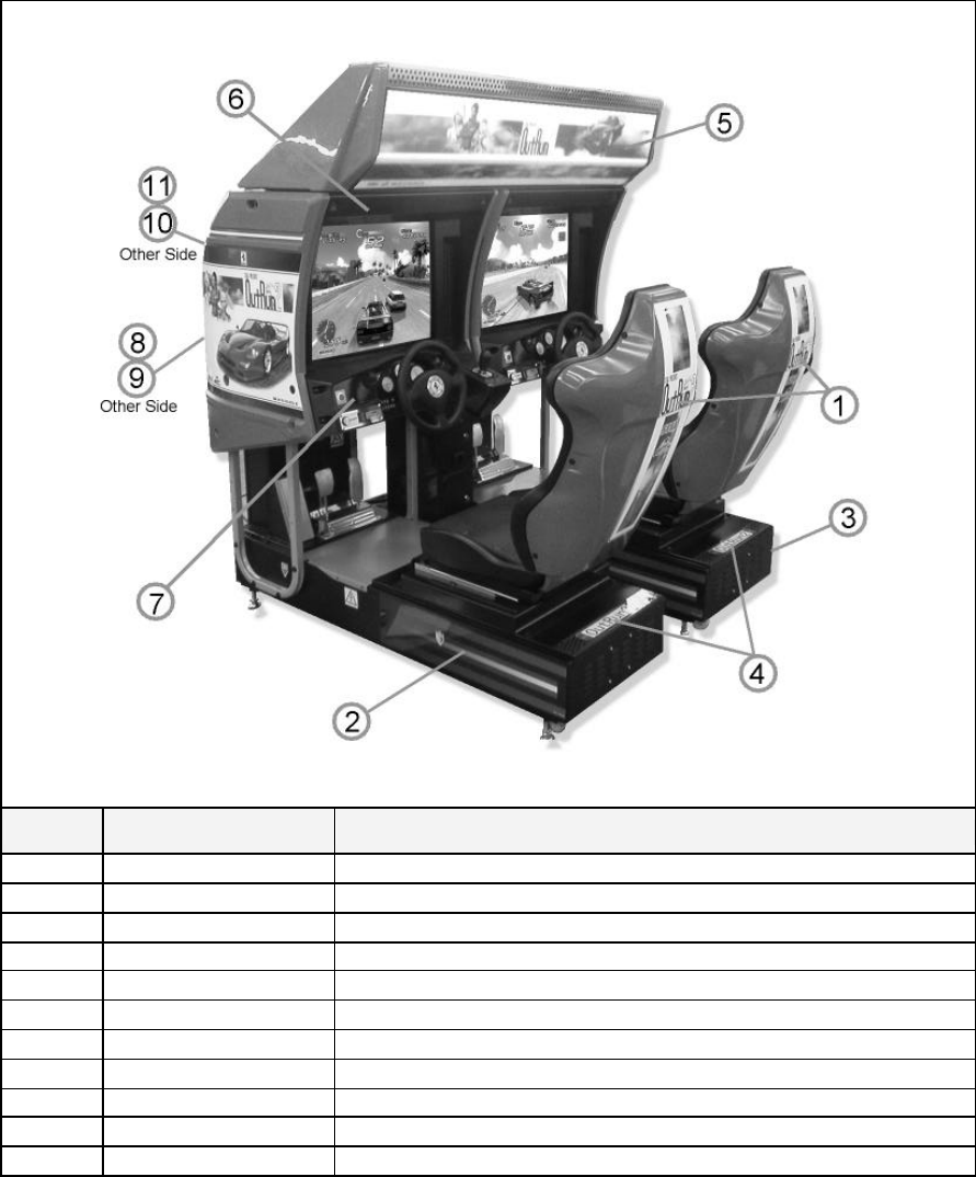
106
7. DESIGN RELATED PARTS
ITEM PART NO, DESCRIPTION
1 ORT-1603-BUK STICKER SEAT BACK
2 ORT-1502UK STICKER BASE L
3 ORT-1503UK STICKER BASE R
4 ORT-1504UK STICKER BASE LID
5 ORT-0215UK BILLBOARD PLATE ORT TWIN
6 422-0922UK PLAY INSTR SH ORT TWIN MULTI
7 422-0923UK SUB INSTR SH ORT TWIN MULTI
8 ORT-1551-AUK STICKER COVER PANEL L
9 ORT-1556-AUK STICKER COVER PANEL R
10 ORT-1551-BUK STICKER LINE L
11 ORT-1556-BUK STICKER LINE R
107
8. PARTS LIST
8.1. Assembly Structure
ORT-00001UK TOP ASSY OUTRUN 2 TWIN
ORT-10001UK (x2) ASSY COCKPIT 1P
DUT-1120UK ASSY SUB MAIN BASE
ORT-1550UK ASSY MONITOR COVER L 2P
APC-1560 ASSY SPEAKER L
ORT-1550UK ASSY MONITOR COVER R 2P
APC-1565 ASSY SPEAKER R
ORT-2000UK ASSY CONTROL PANEL
SPG-2500 ASSY HANDLE MECHA
ORT-2100 ASSY SW PLATE
ORT-1100UK ASSY PEDAL BASE ORT
SPG-2200 ASSY BRAKE & ACCELL
ORT-1600UK ASSY SEAT TWIN 1P
ORT-4500UK ASSY MAIN BD
ORT-4600UK ASSYELEC BD
FRI 1510UK ASSY BASE LID R
ORT-INST-TW ASSY INSTALLATION KIT ORT TWIN
ORT-0200UK ASSY BILLBOARD
FRI-0300UK ASSY COINCHUTE TOWER FRI
ORT-0500UK ASSY WIRE COVER ORT TWIN
ORT-0400UK ASSY AC BRKT MAIN
ORT-0700UK ASSY AC BRKT SUB
ORT-4560UKASSY LAN COM2
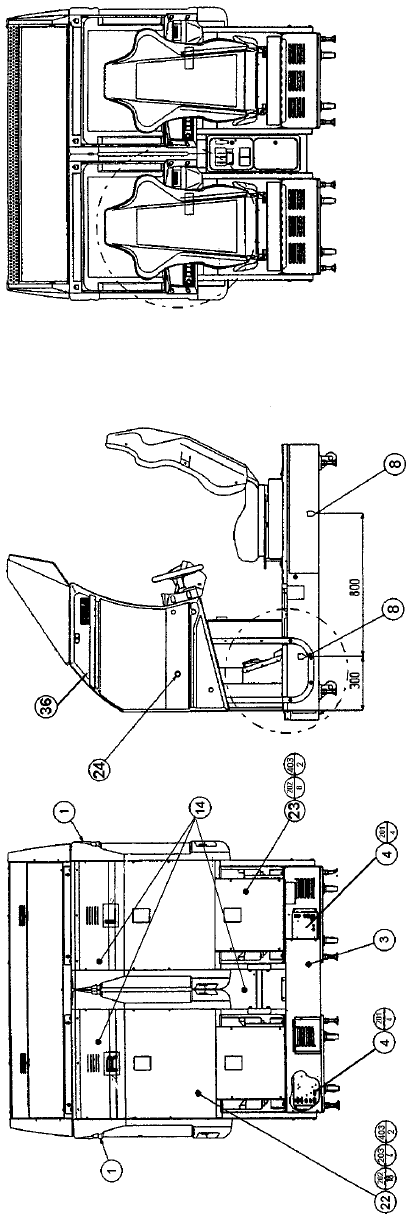
108
8.2. ORT-00001UK TOP ASSY OUTRUN2 TWIN

109
ITEM
PART NO. QTY
DESCRIPTION COMPONENT REF.
1 ORT-10001UK 2 ASSY COCKPIT 1P
3 ORT-INST-TW 1 ASSY INSTALLATION KIT ORT TWIN
4 ORT-0400UK 1 ASSY AC BRKT MAIN
5 ORT-0700UK 1 ASSY AC BRKT SUB
8 421-7020UK 4 STICKER CAUTION FORK
9 LB1102 6 STICKER DANGEROUS VOLTAGE BACK LIDS-4, REAR FLOOR-2
10 ORT-4560UK 1 ASSY LAN COM2 PUT IN LEFT HAND UNIT
12 421-7987-ORT-T 1 STICKER ELEC SPEC ORT TW MAIN CA BI, LHS OF MAIN
BASE
14 421-7988-91UK 3 STICKER SERIAL NUMBER UK 1P-1,2P-2,CCT INSIDE TOP
DOOR
15 421-8543UK 1 STICKER CABINET L UK 1P
16 421-8544UK 1 STICKER CABINET R UK 2P
18 SGM-3863 2 POLY COVER 1800X950X1700
19 SPG-0005 24 BLIND CAP 1P-LHS-12, 2P -RHS -12
22 INY -0004 2 BACK LID INY
23 DYN-0008XUK 2 BACK LID B UK
24 ORT-1551-AUK 1 STICKER COVER PANEL L
25 ORT-1556-AUK 1 STICKER COVER PANEL R
27 LB1046 1 LABEL TESTED FOR ELEC. SAFETY
28 RAL-XXXX-13UK 2 LOCK COVER UK (R.FLOORS)-2
36 ORT-1551-BUK 1 STICKER LINE L
37 ORT-1556-BUK 1 STICKER LINE R
101 601-8956-01 1 EARTH OUTLET WK3001W LEFT UNIT
102 440034 3 FERRITE-TDK-ZCAT-3035-1330
201 000-P00412-WB 8 M4X12 MSCR PAN W/FS BLK (4)-4,(5)-4
202 000-P00408-WB 26 M4X8 MSCR PAN W/FS BLK (22)-18,(23)-8
203 010-P00412 4 M4X12 S-TITE PAN PAS (22)-4
204 008-T00408-0C 16 M4X8 TMP PRF TH CRM (28)-8,(F.FLOORS)-8
205 029-B00620-0B 4 M6X20 SKT BH BLK (R.FLOORS)-4
206 060-S00600-0B 4 M6 WSHR SPR BLK (R.FLOORS)-4
207 060-F00600-0B 4 M6 WSHR FORM A FLT BLK (R.FLOORS)-4
212 050-F00400 2 M4 NUT FLG SER PAS (10)-2
213 068-441616 2 M4 WSHR 16OD FLT PAS (10)-2
214 012-P03512-F 2 N6X1/2" S/TAP FLG PAS (101)-2
303 ORT-64001UK 1 WH POWER HUB
401 PK0342 2 SLEEVE COCKPIT ORT TWIN
402 PK0034 2 PALLET WOODEN RALLY
403 PK0342-LID 2 LID ORT TWIN
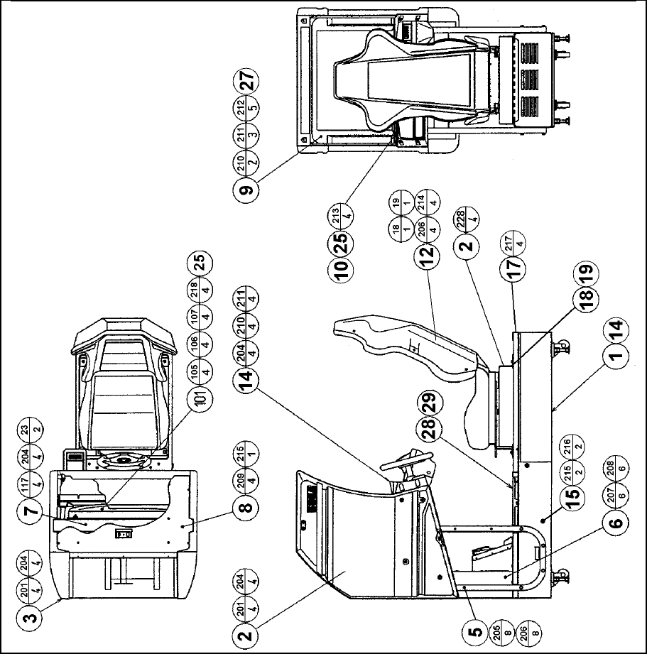
110
8.3. ORT-10001UK ASSY COCKPIT 1P

111
ITEM
PART NO. QTY
DESCRIPTION COMPONENT REF.
1 DUT-1120UK 1 ASSY SUB MAIN BASE
2 ORT-1550UK 1 ASSY MONITOR COVER L 2P
3 ORT-1555UK 1 ASSY MONITOR COVER R 2P
4 ORT-2000UK 1 ASSY CONTROL PANEL
5 POD-1023UK 1 MONITOR STAND
6 ORT-1100UK 1 ASSY PEDAL BASE ORT
7 POD-1021UK 1 MONITOR SUPPORT
8 DUT-1008UK 1 ROOF LID DUT
9 POD-1022 1 MONITOR MASK
10 SPG-1005 1 MASK HOLDER
12 ORT-1600UK 1 ASSY SEAT TWIN 1P
14 ORT-4500UK 1 ASSY MAIN BD
15 ORT-4600UK 1 ASSY ELEC BD
17 FRI-1510UK 1 ASSY BASE LID R
18 RAL-2007 1 RUBBER HOLDER R TWIN (12)-1
19 RAL-2008 1 RUBBER HOLDER L TWIN (12)-1
20 ORT-1502UK 1 STICKER BASE L
21 ORT-1503UK 1 STICKER BASE R
22 ORT-1504UK 1 STICKER BASE LID (17)-1
23 POD-1026UK 4 CRT SPACER (POD) (5)-2,(7)-2
24 DUT-2031UK 1 FRONT FLOOR UK DUT FIX DOWN AT NEXT LEVEL UP
25 SRT-1009UK 1 MONITOR SPASHGUARD SRT TW FIX TO (10)
26 SRT-2031UK 0.9 NEOPRENE RUBBER STRIP 10X3mm (24)-0.5,(1)-0.4 4X10cm STRIPS
27 OS1004 0.705
DRAFT EXCLDR 4 X7MM BLK x 10M (9)-705mm ON FRONT LIP
30 440-WS0220UK 1 WARNING STICKER TRAP HAZARD NEXT TO STEERING GEARS
101 200-5949 1 ASSY CLR DSPL 29 TYPE 31K UK
105 280-5112 4 BUSH FOR TV (101)-4
106 280-5113 4 COLLAR FOR TV (101)-4
107 068-652516 4 M6 WSHR 25OD FLT PAS (101)-4
108 280-L00716-OS 3 STANDOFF 7OD 4ID 16L (101)-3 REMOTE BD
109 601-6231-C100 2 EDGING NEW TYPE TOP OF WIRE COVER -2
110 601-6231-D100 2 EDGING NEW TYPE INSIDE OF PEDAL BASE -2
111 260-0011-02 1 AXIAL FLOW FAN AC100V 50-60Hz
112
113 FN1012 2 MESH GUARD METAL 120mm FAN (111)-2
114 OS1195 8 RIVET SNAP MOSS SR1811 (113)-8
115 280-A00900-A 20 ROUTER TWIST D9 ADH
116 280-A00748-PM 4 ROUTER TWIST D7 SO4.8PA MONITOR STAND HORIZONTAL
BAR
117 280-A02048-PM 12 ROUTER TWIST D20 SO4.8PA WIRE COVER BOX 2X4 CORNER
DROP
201 030-000840-SB 12 M8X40 BLT W/S BLK (2)-4,(3)-4,(7)-4
202 008-B00825-0B 6 M8X25 TMP PRF BH BLK (4)-6
203 060-S00800-0B 6 M8 WSHR SPR BLK (4)-6
204 060-F00800-0B 18 M8 WSHR FORM A FLT BLK (2)-4,(3)-4,(4)-6,(7)-4
205 030-000850-SB 8 M8X50 BLT W/S BLK (5)-8
206 068-852216-0B 12 M8 WSHR 22OD FLT BLK (5)-8,(12)-4
207 030-000616-SB 6 M6X16 BLT W/S BLK (6)-6
208 068-651616-0B 6 M6 WSHR 16OD FLT BLK (6)-6
209 000-P00408-WB 6 M4X8 MSCR PAN W/FS BLK (8)-4,(6)-2

112
Cont.
ITEM
PART NO. QTY
DESCRIPTION COMPONENT REF.
210 000-T00530-0B 2 M5X30 MSCR TH BLK (9)-2
211 000-T00512-0B 3 M5X12 MSCR TH BLK (9)-3
212 068-552016-0B 5 M5 WSHR 20OD FLT BLK (9)-5
213 000-F00512 4 M5X12 MSCR CSK PAS (10)-4
214 030-000820-SB 4 M8X20 BLT W/S BLK (12)-4
215 032-000425 4 M4X25 W/BLT PAS (14)-2,(15)-2
216 068-441616 4 M4 WSHR 16OD FLT PAS (14)-2,(15)-2
217 008-T00512-0B 4 M5X12 TMP PRF TH BLK (17)-4
218 050-F00600 4 M6 NUT FLG SER PAS (101)-4
219 000-P00320 3 M3X20 MSCR PAN PAS (101)-3 REMOTE BD
220 012-HB0512 8 N10X1/2" S/TAP HEX B PAS (111)-8
221 060-F00500 8 M5 WSHR FORM A FLT PAS (111)-8
301 TOF-60100UK 1 WH EXT VIEW BUTTON A
306 600-6373-77-91 1 WIRE HARNESS PLAYER SEL EXT B
307 TOF-60101UK 1 WH EXT FRONT SP B
308 FRI-61042UK 1 WIRE HARN EXT VR B
309 NCR-61011UK 1 WIRE HARN VIEW BUTTON B
310 600-7009-2500 1 ASSY RGB CA D-SUB 15P 2500MM
312 FRI-61041UK 1 WIRE HARN EXT MOTOR B
316 POD-61012UK 1 WIRE HARN 100V EXT COCKPIT
317 TOF-60015UK 1 WH EXT ENCODER B
318 NCR-61008UK 1 WH EXT FRONT SP A
319 POD-61026UK 1 WIRE HARN EXT AC UNIT
320 TOF-60103UK 1 WH VTS EXT
323 600-9020-44K 1 WIRE HARN EARTH 200mm M4/M4 K MON STAND TO WIRE COVER
BOX
324 600-9100-44K 2 WIRE HARN EARTH 1000mm M4/M4 K MON STAND TO MON SUPPORT
& C.PNL
325 600-9020-44K 1 WIRE HARN EARTH 200mm M4/M4 K MON SUPPORT TO ROOF LID
326 600-9060-46K 1 WIRE HARN EARTH 600mm M4/M6 K MON STAND TO LH BOT OF 101
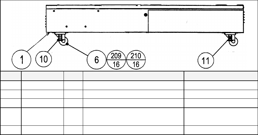
113
8.4. DUT-1120UK ASSY SUB MAIN BASE
ITEM
PART NO. QTY
DESCRIPTION COMPONENT REF.
1 DUT-1121UK 1 MAIN BASE
6 MA1007 4 CASTOR SWIVEL 63mm NYLON
10 601-5699UK-01 2 LEG ADJ M16X100 1L/NUT
11 601-5699UK-03 2 LEG ADJ M16X100 3 L/NUT
209 030-000816 16 M8X16 BLT PAS
210 060-S00800 16 M8 WSHR SPR PAS
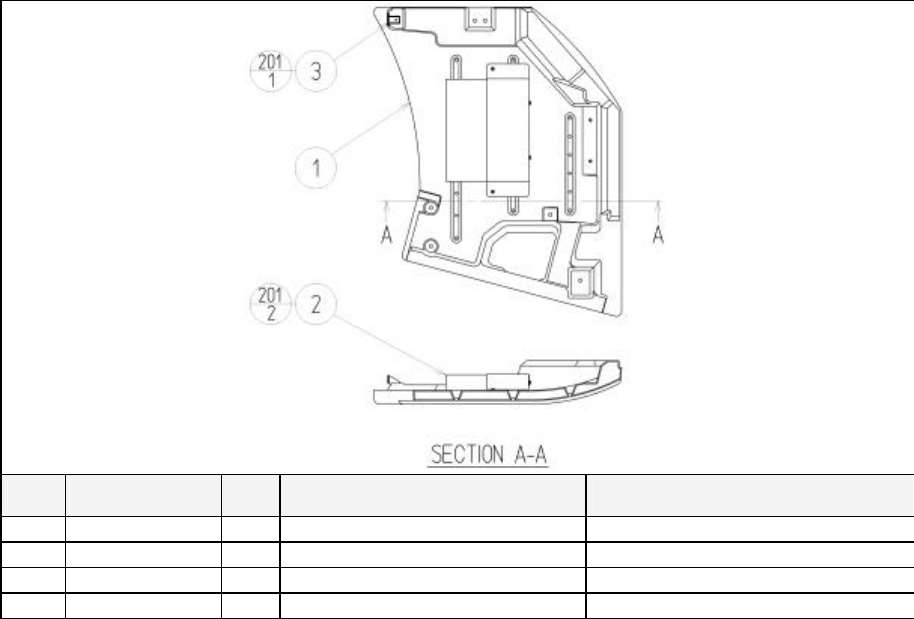
114
8.5. ORT-1550UK ASSY MONITOR COVER L 2P
ITEM
PART NO. QTY
DESCRIPTION COMPONENT REF.
1 FRI-1035X-A 1 COVER PANEL L BLANK
2 APC-1560 1 ASSY SPEAKER L
3 DYN-1032UK 1 MASK BRKT
201 000-P00408-W 3 M4X8 MSCR PAN W/FS PAS (2)-2,(3)-1
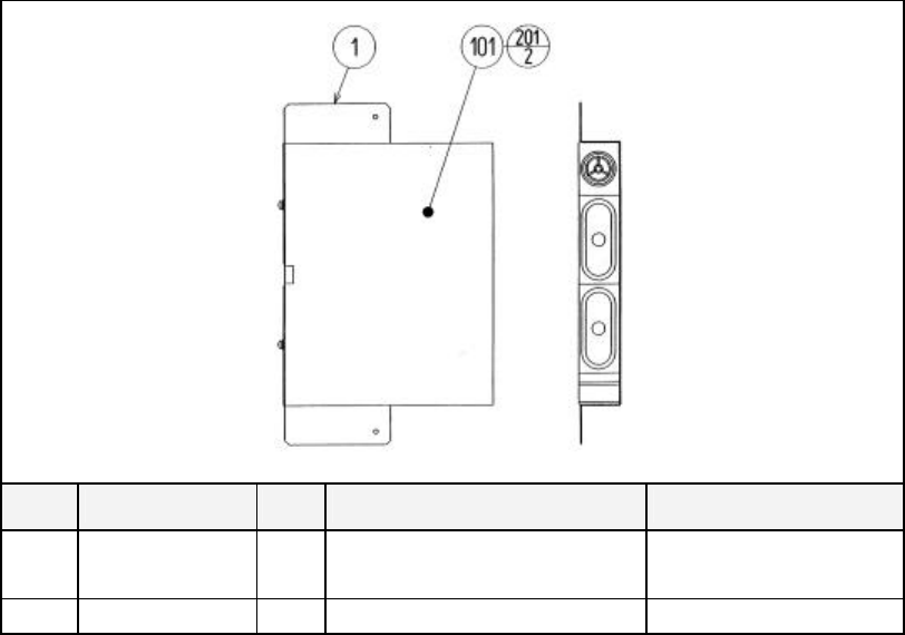
115
8.6. APC-1560 ASSY SPEAKER L
ITEM
PART NO. QTY
DESCRIPTION COMPONENT REF.
1 APC-1561 1 SPEAKER BRKT
101 130-5156 1 SPEAKER BOX 8OHM 20W TWEETER @ TOP
201 000-P00512-W 2 M SCR PH W/FS M5X12 (101)-2
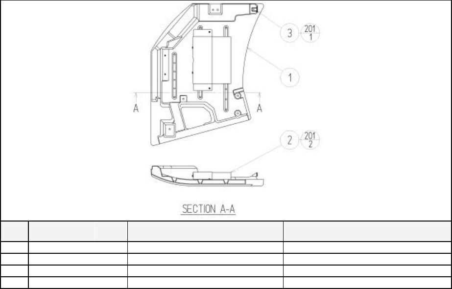
116
8.7. ORT-1555UK ASSY MONITOR COVER R 2P
ITEM
PART NO. QTY DESCRIPTION COMPONENT REF.
1 FRI-1036X-A 1 COVER PANEL R BLANK
2 APC-1565 1 ASSY SPEAKER R
3 DYN-1032UK 1 MASK BRKT
201 000-P00408-W 3 M4X8 MSCR PAN W/FS PAS (2)-2,(3)-1
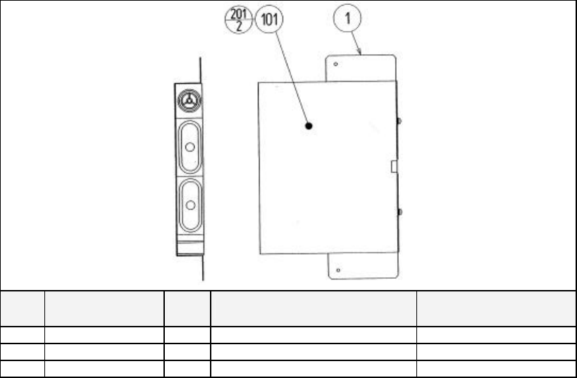
117
8.8. APC-1565 ASSY SPEAKER R
ITEM
PART NO. QTY DESCRIPTION COMPONENT REF.
1 APC-1561 1 SPEAKER BRKT
101 130-5156 1 SPEAKER BOX 8OHM 20W TWEETER @ TOP
201 000-P00512-W 2 M SCR PH W/FS M5X12 (101)-2
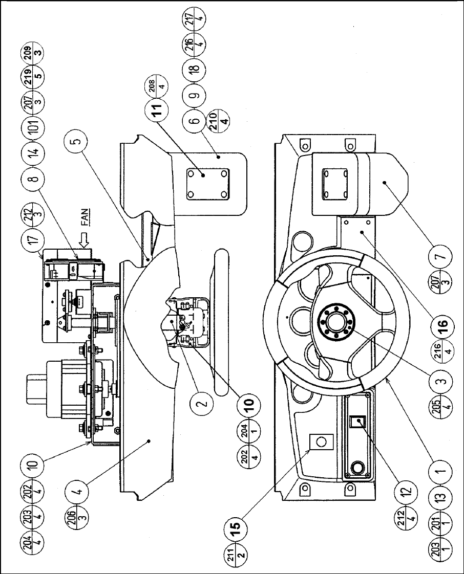
118
8.9. ORT-2000UK ASSY CONTROL PANEL

119
ITEM PART NO. QTY DESCRIPTION COMPONENT REF.
1 SPG-2001 1 STEERING WHEEL
2 DYN-1209X 1 HANDLE COLLAR
3 FRI-2002 1 STEERING EMBLEM FRI
4 JBA-2001 1 CONTROL PANEL COVER
5 FRI-1202UK 1 CONTROL PANEL BRKT TWIN
6 INY-1204 1 SHIFT COVER INY
7 DYN-1223X 1 SHIFT COVER B
8 SRT-1203UK 1 FAN BRKT UK
9 LMN-1202 1 SHIFT BASE
10 SPG-2500 1 ASSY HANDLE MECHA
11 610-0408-91 1 UP/DOWN SHIFTER AL
12 ORT-2100 1 ASSY SW PLATE
13 SPG-2039 1 SPACER RING (1)-1
14 FN1012 1 MESH GUARD METAL 120mm FAN
15 117-5164UK 1 PLATE START 37x42 UK
16 DYN-0010UK 1 DENOMI PLATE
101 260-0011-02 1 AXIAL FLOW FAN AC100V 50-60HZ AIRFLOW TOWARDS
102 280-A01200-A 4 ROUTER TWIST D12 ADH
103 280-A02000-A 1 ROUTER TWIST D20 ADH
104 280-A02048-PM 2 ROUTER TWIST D20 SO4.8 PAN LG
107 OS1195 5 RIVET SNAP MOSS SR1811 (14)-5
108 509-5440 1 PUSH BTN SW IT GRN W/L DC 14V (15)-1
201 020-000820 1 M8X20 BLT PAS (1)-1 (USE ANAEROBIC
202 060-F00800 4 M8 WSHR FORM A FLT PAS (10)-4
203 060-S00800 5 M8 WSHR SPR PAS (1)-1,(10)-4
204 050-U00800 4 M8 NUT NYLOK PAS (10)-4
205 FAS-200013 4 M4X16 SKT CAP CRM (3)-4
206 000-T00416-0B 3 M4X16 MSCR TH BLK (4)-3
207 000-P00412-W 6 M4X12 MSCR PAN W/FS PAS (7)-3,(8)-2,(FAN EARTH)-
208 008-T00516-0B 4 M5X16 TMP PRF TH BLK (11)-4
209 000-P00312-W 3 M3X12 MSCR PAN W/FS PAS (101)-3
210 030-000820-S 4 M8X20 BLT W/S PAS (9)-4
211 050-F00300 2 M3 NUT FLG SER PAS (15)-2
212 000-T00412-0C 4 M4X12 MSCR TH CRM (12)-4
215 050-F00400 1 M4 NUT FLG SER PAS EARTHS - 2
216 000-T00412-0B 4 M4X12 MSCR TH BLK (16)-4
301 600-6873-043 1 WIRE HARN VIEW BUTTON
302 TOF-60018UK 1 WH EXT SHIFTER
303 CKT-62037UK 1 WIRE HARN ENCODER EXT 2
304 CKT-62036UK 1 WIRE HARN SERVO OUTPUT EXT 2
305 ORT-61047UK 1 WIRE HARN CONT PNL FAN
306 TOF-60016UK 1 WH EXT VOLUME C
308 TOT-61078UK 1 WH PLAYER SELECT SW
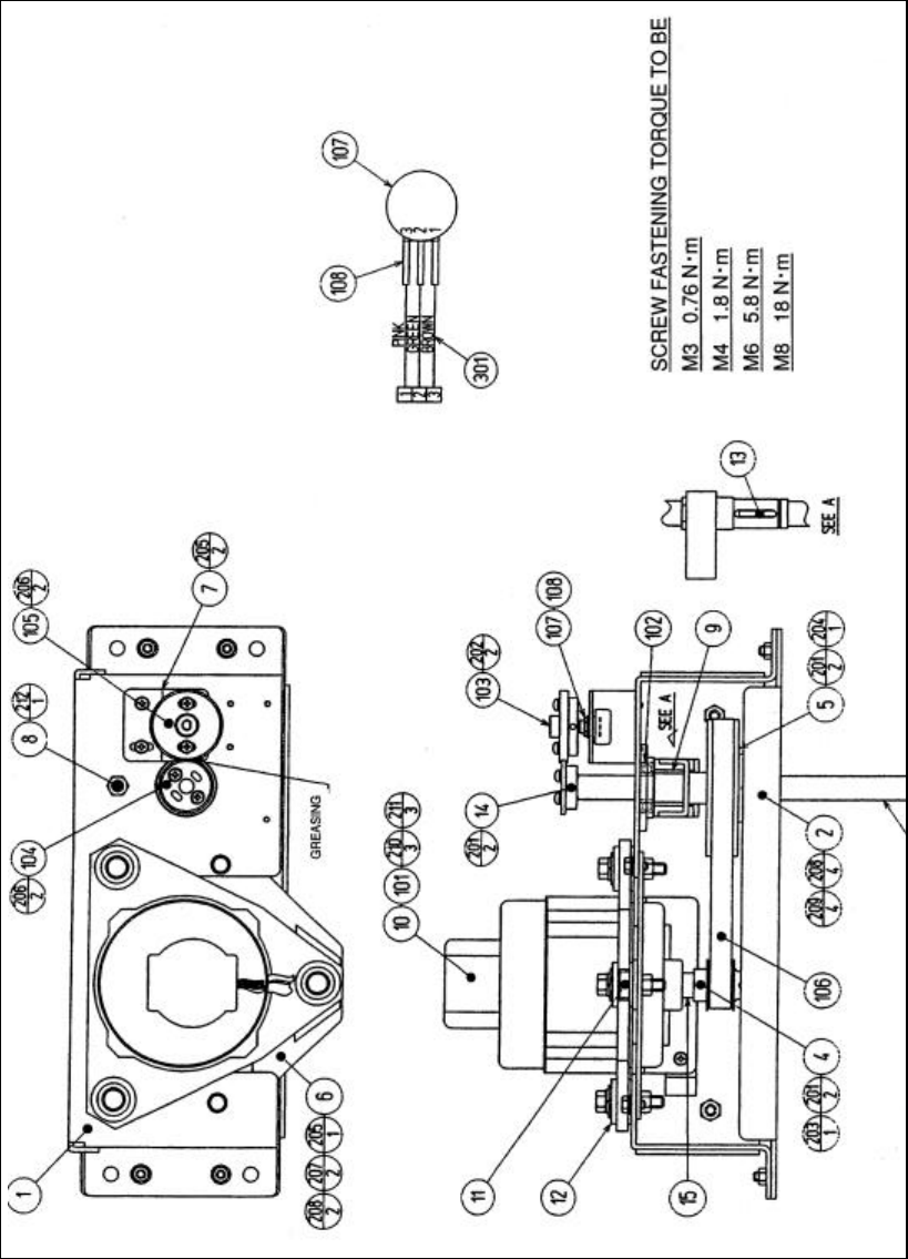
120
8.10. SPG-2500 ASSY HANDLE MECHA

121
ITEM PART NO. QTY DESCRIPTION COMPONENT REF.
1 SPG-2500 1 HANDLE BASE
2 SPG-2500 1 BASE LID
3 SPG-2500 1 HANDLE SHAFT
4 SPG-2500 1 PULLEY 20 S5M
5 SPG-2500 1 PULLEY 60 S5M
6 SPG-2500 1 MOTOR BRKT
7 SPG-2500 1 VR BRKT
8 SPG-2500 1 STOPPER BOLT
9 SPG-2500 1 STOPPER RUBBER
10 SPG-2500 1 KEY 4X4X40
11 SPG-2500 3 MOTOR SPACER
12 SPG-2500 3 MOTOR COLLAR
13 SPG-2500 1 STOPPER KEY
14 SPG-2500 1 ADJUST RING
15 SPG-2500 1 MOTOR SHAFT COLLAR
101 SPG-2500 1 SERVO MOTOR 500W NEW
102 SPG-2500 2 BEARING 17 (NSK 6003ZZ)
103 SPG-2500 1 GEAR HOLDER
104 SPG-2500 1 GEAR 48
105 SPG-2500 1 GEAR 64
106 SPG-2500 1 TIMING BELT (150 S5M 475)
107 SPG-2500 1 VOL CONT B-5K OHM
108 SPG-2500 3 SUMITUBE F F 20MM
201 SPG-2500 6 SET SCR HEX SKT CUP P M4X8
202 SPG-2500 2 SET SCR HEX SKT CUP P M3X8
203 SPG-2500 1 STP RING BLK OZ S12
204 SPG-2500 1 STP RING BLK OZ S20
205 SPG-2500 3 M SCR PH W/FS M4X8
206 SPG-2500 4 M SCR PH W/FS M4X12
207 SPG-2500 2 HEX BLT W/S M6X12
208 SPG-2500 6 FLT WSHR M6
209 SPG-2500 4 U NUT M6
210 SPG-2500 3 HEX BLT W/S M8X40
211 SPG-2500 3 FLT WSHR 8.5-22 X1.6
212 SPG-2500 1 U NUT M8
301 SPG-2500 1 WIRE HARN ASSY HANDLE MECHA VR
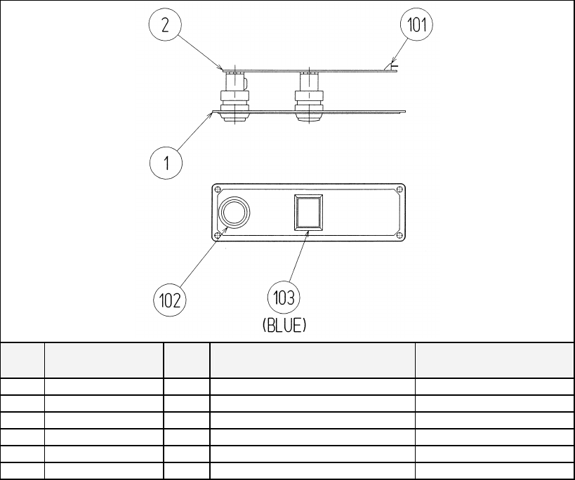
122
8.11. ORT-2100UK-ASSY SW PLATE
ITEM
PART NO. QTY DESCRIPTION COMPONENT REF.
1 ORT-2101 1 BUTTON PLATE
2 ORT-2102 1 STICKER START/VIEW
3 171-6478B 1 PC BD LIGHTING SWX5
101 212-5205-12 1 CONN JST M 12P RTA
102 509-5560-Y 1 PB SW W/L 6V 1L Y LW1L-15VY
103 509-5561-R 1 PB SW W/L 6V 5L R LW5L-15VR
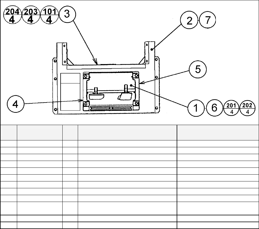
123
8.12. ORT-1100UK ASSY PEDAL BASE ORT
ITEM
PART NO. QTY
DESCRIPTION COMPONENT REF.
1 SPG-2200 1 ASSY BRAKE & ACCELL
2 TOF-1501UK 1 PEDAL BASE
3 FZR -1021UK 1 WIRE COVER BOX
4 SPG-2222UK 1 ANTI FINGER TRAP PLATE LEFT
5 SPG-2223UK 1 ANTI FINGER TRAP PLATE RIGHT
6 SPG-2224UK 1 PEDAL GASKET
7 SRT-2031UK 0.52
NEOPRENE RUBBER STRIP 10 (2)-520mm X1 INSIDE FLANGE
101 280-A01200-A 6 ROUTER TWIST D12 ADH WIRE COVER BOX
201 068-852216-0B 4 M8 WSHR 22OD FLT BLK (1)-4
202 030-000820-SB 4 M8X20 BLT W/S BLK (1)-4
203 000-P00408-WB 4 M4X8 MSCR PAN W/FS BLK (3)-4
204 050-F00400 3 M4 NUT FLG SER PAS (3)-3 EARTHS
301 600-9050-44K 1 WIRE HARN EARTH 500mm M4/M4 K WIRE COVER TO MAIN BASE
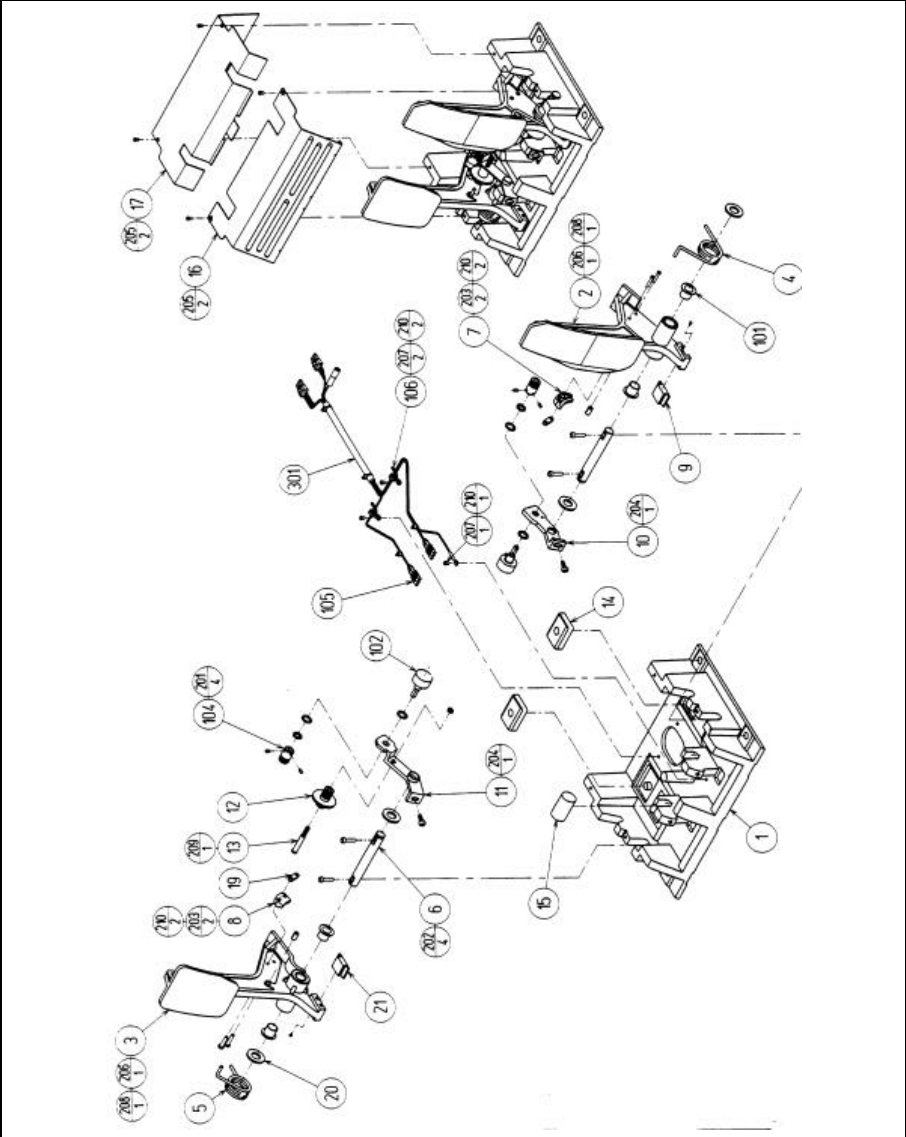
124
8.13. SPG-2200 ASSY BRAKE & ACCELL

125
ITEM
PART NO. QTY
DESCRIPTION COMPONENT REF.
1 SPG-2201 1 BASE
2 SPG-2202 1 ACCEL PEDAL
3 SPG-2203 1 BRAKE PEDAL
4 SPG-2204 1 ACCEL SPRING
5 SPG-2205 1 BRAKE SPRING
6 SPG-2206 2 SHAFT
7 SPG-2207 1 ACCEL
8 SPG-2208 1 BRAKE GEAR
9 SPG-2209 1 NEUTRAL STOPPER
10 SPG-2210 1 VR PLATE ACCEL
11 SPG-2211 1 VR PLATE BRAKE
12 SPG-2212 1 AMPL GEAR
13 SPG-2213 1 GEAR SHAFT
14 SPG-2214 2 STOPPER
15 SPG-2215 1 RUBBER CUSHION
16 SPG-2216 1 COVER
17 SPG-2217 1 VR COVER
19 SPG-2219 2 GEAR STAY
20 SPG-2220 4 WSHR
21 SPG-2221 1 NEUTRAL STOPPR D
101 100-5263 4 BEARING 12 (OILES 80F-1212)
102 220-5484 2 VOL CONT B-5K OHM
104 601-7944 2 GEAR 15
105 310-5029-F15 6 SUNITUBE F F15MM
106 280-0419 2 HARNESS LUG
201 028-A00304-P 4 SET SCR HEX SKT CUP P M3X4
202 020-000516-OZ 4 HEX SKT H CAP SCR BLK OZ M5X16
203 000-P00420 4 M SCR PH M4X20
204 000-P00508-W 2 M SCR PH W/FS M5X8
205 000-T00408-OC 4 M SCR TH CRM M4X8
206 FAS-450005 2 SPR PIN BLK OZ 6X10
207 000-P00405 3 M SCR PH M4X5
208 FAS-000001 2 M SCR TH CRM M3X6
209 050-H00500 1 HEX NUT M5
210 060-F00400 7 FLT WSHR M4
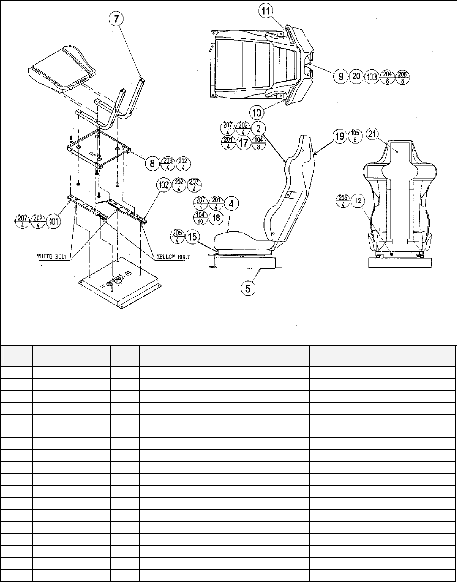
126
8.14. ORT-1600UK ASSY SEAT TWIN 1P
ITEM
PART NO. QTY
DESCRIPTION COMPONENT REF.
2 SPG-2401-AUK 1 UPPER SEAT BLANK
4 SPG-2402-AUK 1 LOWER SEAT BLANK
5 STC-1603 1 SEAT BASE
7 STC-1604 2 SEAT FRAME
8 STC-1606 1 SEAT MOUNT TRAY
9 STC-1607 2 SP MOUNT BRKT
10 STC-1608 1 SPEAKER NET L
11 STC-1609 1 SPEAKER NET R
12 STC-1610 1 SAFETY GUARD
14 STC-1612 2 PROTECT RUBBER
15 STC-1613 1 SAFETY GUARD F
16 OS1004 0.8 DRAFT EXCLDR 4 X7MM BLK x 10M (103)-0.8M
17 SPG-2401-BUK 1 UPPER SEAT INSERT (2)-1
18 SPG-2402-BUK 1 LOWER SEAT INSERT (4)-1
19 ORT-1601-AUK 1 SEAT REAR COVER BLANK
20 SRT-2409 2 SHOULDER PAD INBETWEEN SPKR NETS &
21 ORT-1603-BUK 1 STICKER SEAT BACK
101 601-9059-91 1 SEAT RAIL L

127
Cont.
ITEM
PART NO. QTY
DESCRIPTION COMPONENT REF.
102 601-9060-91 1 SEAT RAIL R
103 130-5186-91 2 DUMMY SPEAKER
104 280-K02529-WX 18 DRIVE FASTENER 25FH 24L 7.9DIA (17)-8,(18)-10
105 280-5297 6 SCRIVET 8 1K31 (19)-6
201 030-000850-S 8 M8X50 BLT W/S PAS (2)-4,(4)-4
202 068-852216 20 M8 WSHR 22OD FLT PAS (2,4,8,101,102)-4EA
203 030-000816-S 4 M8X16 BLT W/S PAS (8)-4
204 000-P00410-W 8 M4X10 MSCR PAN W/FS PAS (9)-8
205 000-T00408-0B 8 M4X8 MSCR TH BLK (12)-4,(15)-4
206 012-P03512-F 8 N6X1/2" S/TAP FLG PAS (103)-8
207 050-U00800 8 M8 NUT NYLOK PAS (101)-4,(102)-4
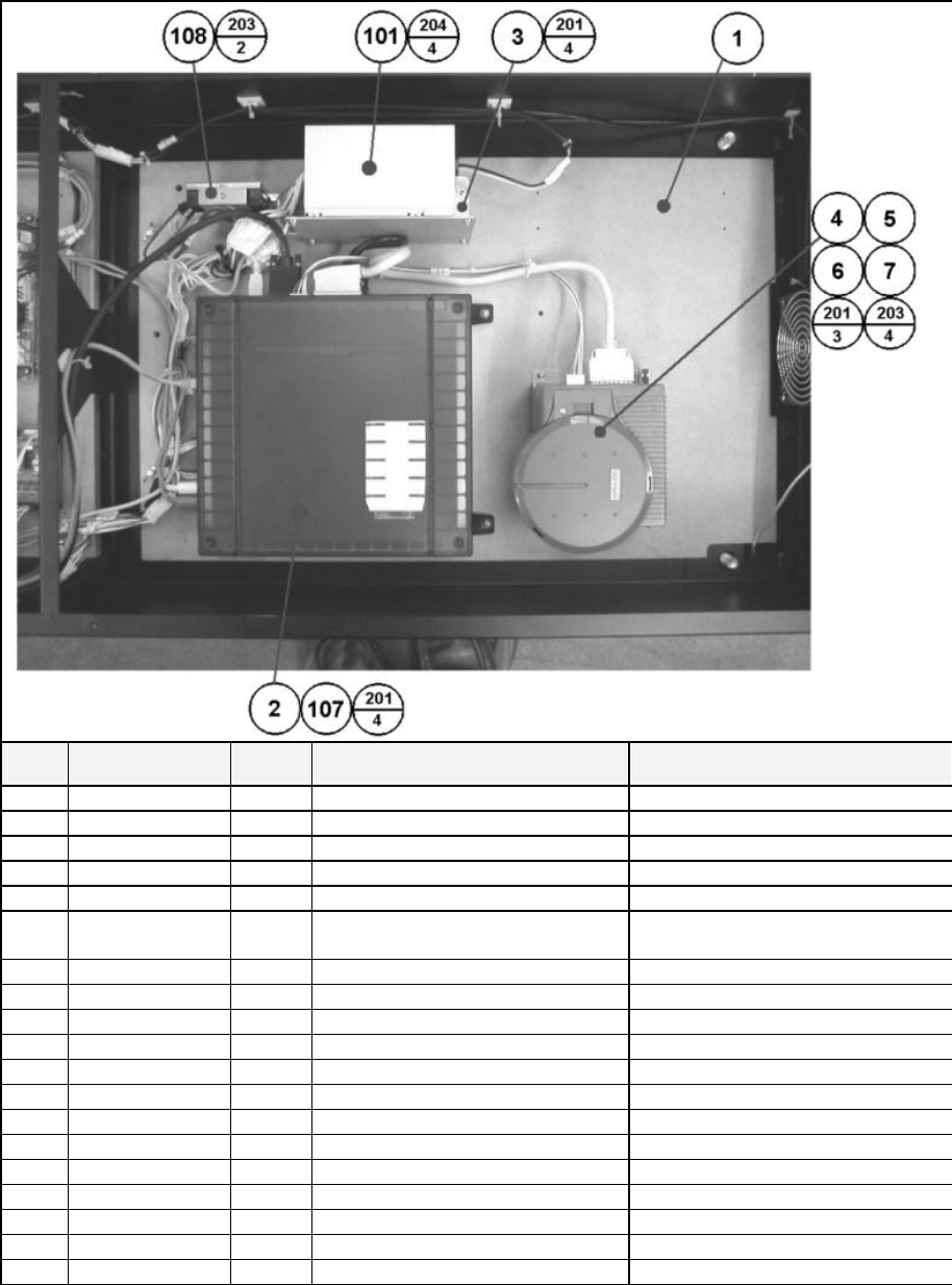
128
8.15. ORT-4500UK ASSY MAIN BD
ITEM
PART NO. QTY DESCRIPTION COMPONENT REF.
1 ORT-4501UK 1 MAIN BD BASE
2 843-0005D-02 1 ASSY CASE BOX ORT EXP
3 APC-4002 1 SW REG BRKT
4 105-5435 1 GD DRIVE BRKT STD
5 LB1111 1 STICKER PLEASE RECYCLE
6 610-0617 1 GD-ROM DRIVE UNIT NAOMI SHIP BOX WITH MACHINE
7 610-0652-0004 1 GD SOFT ORT
8 KEY CHIP
101 400-5443 1 SW REGU FOR CHIHIRO
104 354081 4 TWIST LOK BHKL-450-4
105 354083 4 (A)TWIST N LOK BHKL-750-4
106 280-A00964-WX 6
ROUTER TWIST D09 SO6.4 WOOD
107 LB1101 1 STICKER WARNING BATTERY GAME BD
108 610-0674 1 POWER PROTECT UNIT FOR
201 000-P00416-W 11 M4X16 MSCR PAN W/FS PAS (2)-4,(4)-3,(3)-4
203 012-P00410-F 6 N8X3/8" S/TAP FLG PAS (6)-4,(108)-2
204 000-P00408-W 4 M4X8 MSCR PAN W/FS PAS (101)-4
307 600-7247-500 1 CABLE SCSI ST-L TYPE2 500MM
308 ORT-60101UK 1 WH POWER PROTECT UNIT
309 HDT-60100UK 1 WH POWER GD ROM
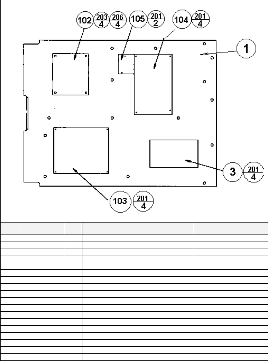
129
8.16. ORT-4600UK ASSY ELEC BD
ITEM
PART NO. QTY
DESCRIPTION COMPONENT REF.
1 TOF-4601UK 1 WOODEN BASE ELEC
3 837-13551-92 1 I/O CONTROL BD FOR JVS
102 560-5394UK 1 TRANSFORMER DUT TW
103 838-13578 1 PWR AMP 2CH & MIXER
104 838-14174 1 SERVO MOTOR DRIVE BD MIDI
105 838-11856CE-02 1 CONNECT BD W/FUSE 6.3A CE
107 354081 11 TWIST LOK BHKL-450-4 HOLES IN BASE
108 354083 10 (A)TWIST N LOK BHKL-750-4 HOLES IN BASE
109 280-A00964-WX 12 ROUTER TWIST D09 SO6.4 WOOD X HOLES IN BASE
201 012-P00325 14 N4X1" S/TAP PAN PAS (3)-4,(103)-4,(104)-4,(105)-2
203 000-P00416-W 4 M4X16 MSCR PH W/FS PAS (102)-4
206 068-441616 4 M4 WSHR 16OD FLT PAS (102)-4
301 600-7141-100 1 CABLE JVS TYPE A-B 100CM
302 600-6985-006UK 1 WIRE HARN 100V OUT
303 FRI-61003UK 1 WIRE HARN CONN BD B
305 FRI-61027UK 1 WIRE HARN EXT AC100V A
306 TOF-60104UK 1 PWR AMP 14V AC IN
307 NCR-61002UK 1 WH AMP VR

130
Cont.
ITEM
PART NO. QTY
DESCRIPTION COMPONENT REF.
309 NCR-61004UK 1 WH AMP SP F
310 ORT-60001UK 1 WH CONN BD OUT A HUB
311 TOF-60007UK 1 WH MIDI
312 TOF-60008UK 1 WH ELEC BD I/O PWR
313 TOF-60009UK 1 WH I/O BD
314 TOF-60105UK 1 WH I/O BRD A/D
315 POD-61057UK 1 WH EARTH AC UNIT
316 FRI-61030UK 1 WIRE HARN EXT MOTOR A
317 TOF-60011UK 1 WH EXT ENCODER A
318 TOF-60021UK 1 WH EXT AC100V B
319 TOF-60006UK 1 WH MAIN BD SOUND
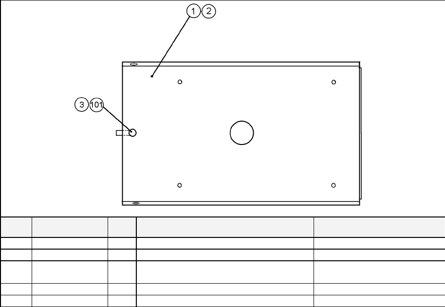
131
8.17. FRI-1510UK ASSY BASE LID R
ITEM
PART NO. QTY
DESCRIPTION COMPONENT REF.
1 DUT-1511UK 1 BASE LID R
2 DUT-1511-CUK 1 GASKET STRIP (1)-1
3 DUT-1511-DUK 1 LOCK TONGUE DUT (101)-1
101 220-5575UK 1 LOCK
201 050-F00400 1 M4 NUT FLG (301)-1
301 600-9020-44K 1 WIRE HARN EARTH 200mm M4/M4 K R.FLOOR TO MAIN BASE

132
8.18. ORT-INST-TW ASSY INSTALLATION KIT ORT TWIN
ITEM
PART NO. QTY
DESCRIPTION COMPONENT REF.
1 ORT-0200UK 1 ASSY BILLBOARD
2 FRI-0300UK 1 ASSY COINCHUTE TOWER FRI
3 ORT-0500UK 1 ASSY WIRE COVER ORT TWIN
4 DYN-0013 1 JOINT PIPE
5 DYN-0006XUK 1 AC COVER B
6 SRT-0018UK 1 AC COVER C
7 DYN-0019UK 1 AC COVER D
8 RAL-XXXX-14UK 1 TIE BRACKET RALLY
9 SPG-0008 2 BILLBOARD HOLDER
10 422-0922UK 1 PLAY INSTR SH ORT TWIN MULTI
11 422-0923UK 1 SUB INSTR SH ORT TWIN MULTI
13 PK0344 1 INST KIT BOX ORT TWIN
18 220-5753 1 VOL CONT B-5K OHM (TOCOS) spare
19 PK0343 0.5 PALLET INST KIT
101 440-CS0186UK 2 STICKER C EPILEPSY MULTI
201 030-000825-SB 20 M8X25 BLT W/S BLK (1,2,4)-4EA,(9)-8
202 068-852216-0B 20 M8 WSHR 22OD FLT BLK (1,2,4)-4EA,(9)-8
203 000-P00412-WB 15 M4X12 MSCR PAN W/FS BLK (3)-5,(5)-4,(6)-2,(7)-4
204 050-F00400 3 M4 NUT FLG SER PAS (AC UNITS)-1EA, (2)-1
401 420-5827 1 SERVICE MANUAL SANWA 31K
402 420-6796-02UK 1 SERVICE MANUAL ORT TWIN
403 OS1019 2 SELF SEAL BAG 9X12.3/4
404 540-0006-01 1 WRENCH M4 TMP PRF
405 540-0007-01 1 WRENCH M5 TMP PRF
406 540-0009-01 1 WRENCH M8 TMP PRF
407 220-5484 1 VOL CONT B-5K OHM
408 SAECE-xxx 1 DECLARATION OF CONFORMITY DECLARATION OF
409 514-5078-5000 2 FUSE 5X20 CERAMIC SB 5000mA
411 420-6620UK 1 SERVICE MANUAL GD ROM SYSTEM
416 509-5704 1 SW MICRO TYPE (OMRON K3L13)
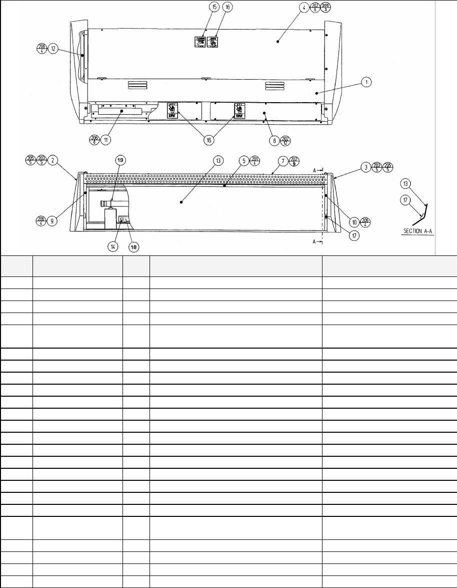
133
8.19. ORT-0200UK ASSY BILLBOARD
ITEM
PART NO. QTY
DESCRIPTION COMPONENT REF.
1 FRI-0201UK 1 BILLBOARD BOX
2 FRI-0202 1 SIDE COVER L
3 FRI-0203 1 SIDE COVER R
4 FRI-0204UK 1 BILLBOARD LID
5 FRI-0205 1 UPPER SASH
7 ORT-0207UK 1 UPPER COVER
8 FRI-0208 2 UPPER LID
9 FRI-0209 1 SASH SIDE L
10 FRI-0210 1 SIDE SASH R
12 VOT-0208 2 SIDE COVER BRKT
13 ORT-0215UK 1 BILLBOARD PLATE ORT TWIN
14 421-7501-10 1 STICKER FL 40W
15 LB1104 1 STICKER CAUTION, HOT SURFACE ON BACK LID
16 LB1102 3 STICKER DANGEROUS VOLTAGE BACK LID-1, UPPER LID-1EA
17 FRI-0211 2 CUSHION SPONGE 40
18 390-5695-40-CUK 1 FL TRAY 110V 40W (T12)
19 390-5695-40-BUK 1 FL TUBE 40W 4' DIA 1.5" T12
20 280-A00900-A 7 ROUTER TWIST D9 ADH
202 000-T00408-0B 27 M4X8 MSCR TH BLK (4)-6,(7)-9,(8)-12
203 000-T00412-0B 10 M4X12 MSCR TH BLK (2)-5,(3)-5
205 068-441616-0B 13 M4 WSHR 16OD FLT BLK (2)-5,(3)-5,(4)-3
206 000-P00408-W 12 M4X8 MSCR PAN W/FS PAS (9)-4,(10)-4,(12)-4
207 050-F00400 5 M4 NUT FLG SER PAS (101)-2,(EARTHS)-3
210 000-P00408 2 M4X8 MSCR PAN PAS (102)-2
302 600-7064-031UK 1 WIRE HARN FL
303 600-9020-44K 1 WIRE HARN EARTH 200mm M4/M4 K B/BD BOX- B/BD LID
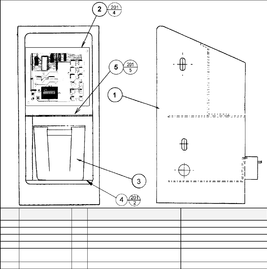
134
8.20. FRI-0300UK ASSY COINCHUTE TOWER FRI
ITEM
PART NO. QTY
DESCRIPTION COMPONENT REF.
1 ECA-0301UK 1 COIN CHUTE TOWER ECA
2 VTS-FRI-T 1 VTS BOARD FRI TWIN
3 PP1087 1 BOX CASH FOR MINI DOOR
4 SRT-0302UK 1 CCT FLOOR TWIN
5 DUT-0302UK 1 COIN PATH PLATE FIX TO TOP OF VAULT ROOF
201 000-P00410-W 11 M4X10 MSCR POSI PAN W/FS (2)-4,(4)-2,(5)-5
301 FRI-61056UK 1 WIRE HARN VTS BOARD
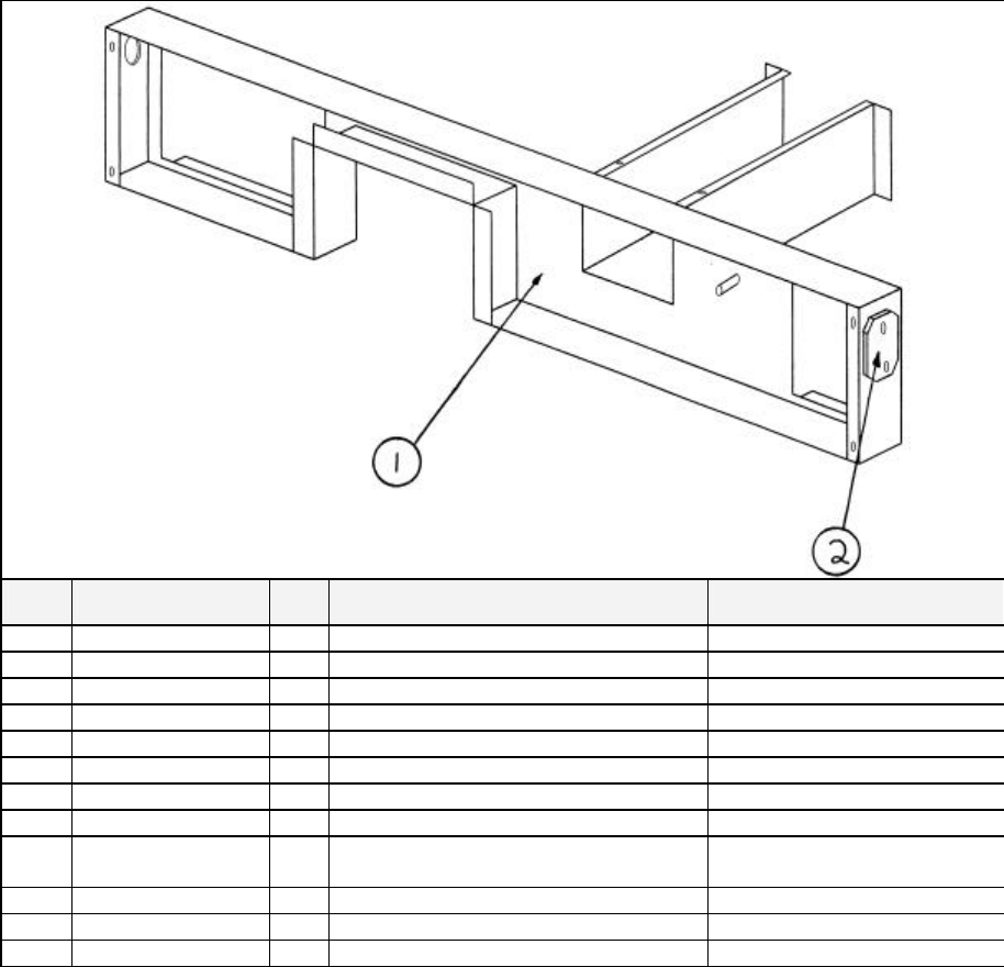
135
8.21. ORT-0500UK ASSY WIRE COVER ORT TWIN
ITEM
PART NO. QTY
DESCRIPTION COMPONENT REF.
1 DYN-0005UK 1 AC COVER A
2 DYN-0009UK 2 HOLE LID (1)-2
101 600-7269-0500 2 ASSY LAN CABLE 0500CM
201 000-P00308-WB 4 M3X8 MSCR PAN W/FS BLK (2)-4
202 050-F00400 1 M4 NUT FLG SER PAS EARTH - 1
203 280-A02000-A 5 ROUTER TWIST D20 ADH (1)-5
301 600-6817-104 1 WIRE HARN EXT AC (SPG)
302 600-6817-102 1 WIRE HARN EXT TOWER L (SPG)
303 600-6817-103 1 WIRE HARN EXT TOWER R (SPG)
304 600-6373-76 1 WIRE HARNESS PLAYER SEL EXT A
305 600-9075-44K 1 WIRE HARN EARTH 750mm M4/M4 K SUB AC-AC COVER
306 600-9030-44K 1 WIRE HARN EARTH 300mm M4/M4 K MAIN AC-AC COVER
307 600-9040-45K 1 WIRE HARN EARTH 400mm M4/M5 K AC COVER - CCT
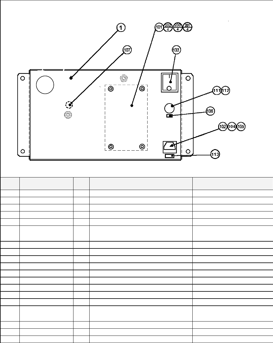
136
8.22. ORT-0400UK ASSY AC BRKT MAIN
ITEM
PART NO. QTY
DESCRIPTION COMPONENT REF.
1 ORT-0401UK 1 AC BRKT UK
101 EP1379 1 FILTER EMI 10A ARCOTRONICS
102 EP1302 1 EUROSOCKET FUSED 1OA 250Vac
103 EP1303 1 SWITCH ROCKER DPST 10A 250Vac
104 514-5078-10000 1 FUSE 5X20 CERAMIC SB 10000mA IEC INLET
105 310-5029-D508 5 HEAT SHRINK SLEEVING 50.8DIA OVER ITEM 102(50MM OVER
SOCKET)
106 421-6595-5000-T 1 STICKER FUSE 5000mA TYPE T FUSE HOLDER
107 LB1096 1 STICKER PROTECTIVE EARTH EARTH POINT INSIDE
111 EP1334 1 FUSE HOLDER 20mm 10A 240Vac
112 514-5078-5000 1 FUSE 5X20 CERAMIC SB 5000mA
113 421-6595-10000T 1 STICKER FUSE 10000mA TYPE T IEC INLET
114 360168 1 SNAP-BUSHING-HEYCO-400 2182
201 060-S00300 4 M3 WSHR SPR PAS (101)-4
202 060-F00300 4 M3 WSHR FORM A FLT PAS (101)-4
203 000-P00310 4 M3X10 MSCR PAN PAS (101)-4
204 050-F00400 3 M4 NUT FLG SER PAS (INSIDE EARTH)-2,(OUTSIDE)-
1
301 600-6873-001UK 1 WIRE HARN XFMR IN
303 600-9030-44K 1 WIRE HARN EARTH 300mm M4/M4 K AC BRKT TO MAIN BASE
304 600-9040-45K 1 WIRE HARN EARTH 400mm M4/M5 K AC BRKT - XFMR
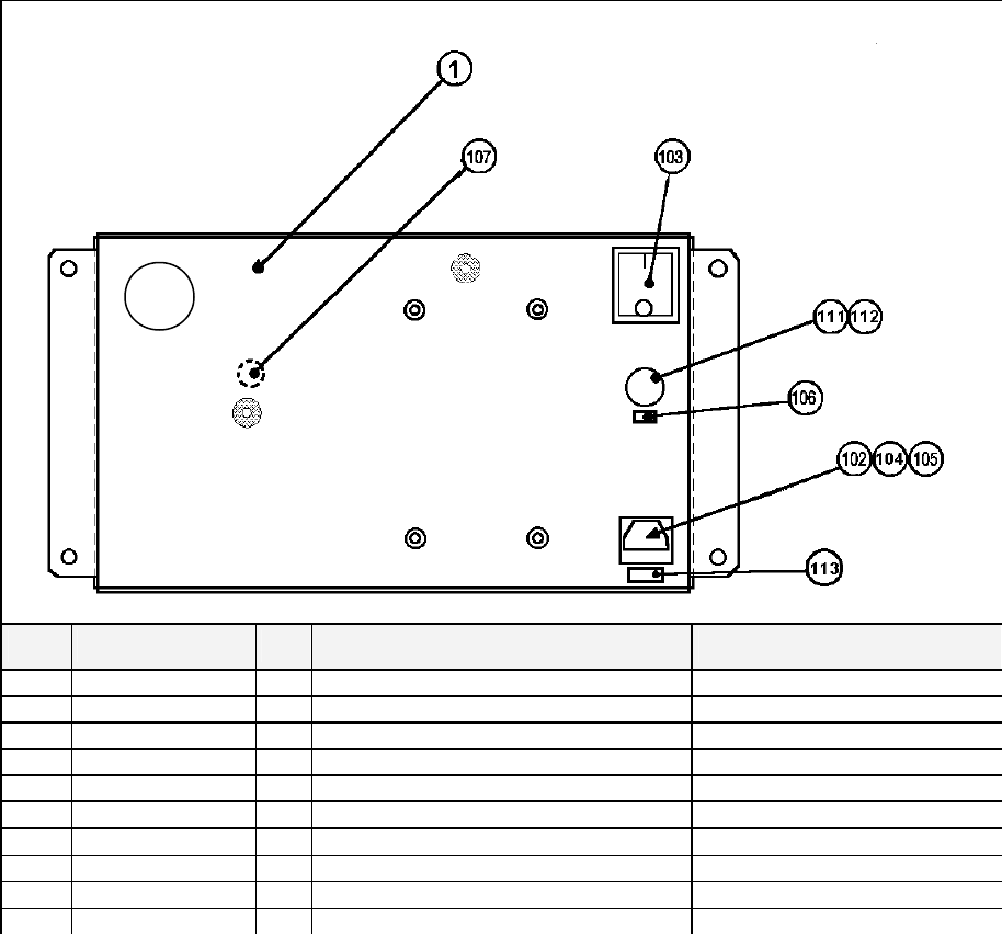
137
8.23. ORT-0700UK ASSY AC BRKT SUB
ITEM
PART NO. QTY
DESCRIPTION COMPONENT REF.
1 ORT-0401UK 1 AC BRKT UK
106 421-6595-5000-T 1 STICKER FUSE 5000mA TYPE T FUSE HOLDER
107 LB1096 1 STICKER PROTECTIVE EARTH EARTH POINT INSIDE
111 EP1334 1 FUSE HOLDER 20mm 10A 240Vac
112 514-5078-5000 1 FUSE 5X20 CERAMIC SB 5000mA
114 360168 1 SNAP-BUSHING-HEYCO-400 2182
204 050-F00400 3 M4 NUT FLG SER PAS (INSIDE EARTH)-2,(OUTSIDE)-1
303 600-9030-44K 1 WIRE HARN EARTH 300mm M4/M4 K AC BRKT TO MAIN BASE
304 600-9040-45K 1 WIRE HARN EARTH 400mm M4/M5 K AC BRKT - XFMR
305 600-6999-201UK 1 WIRE HARN SUB AC BRKT
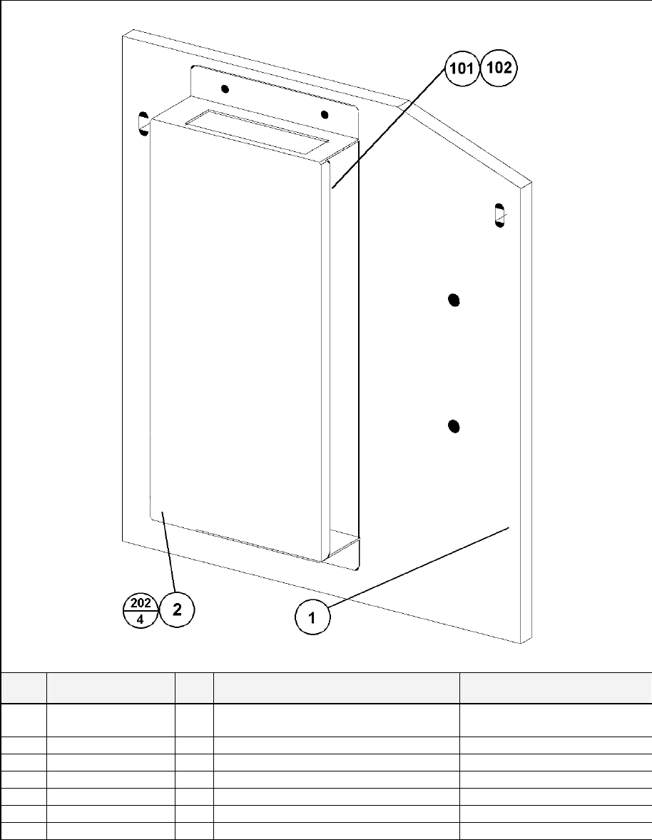
138
8.24. ORT-4560UK ASSY LAN COM2
ITEM
PART NO. QTY
DESCRIPTION COMPONENT REF.
1 ORT-4561UK 1 WOODEN BASE DRIVE TWIN
2 ORT-1005 1 HUB HOLDER
3 VOF-1001 1 BASE HOLDER BRKT
101 601-11351 1 SW HUB MELCO LSW10/100-8HW LEFT UNIT
102 290190 24 TAPE-FOAM-20MM X 4.50MM -101
201 050-F00400 2 M4 NUT FLG SER PAS (3)-2
202 012-P03512-F 4 N6X1/2" S/TAP FLG PAS (2)-4
301 600-7269-0200 1 ASSY LAN CABLE 0200CM

139
9. APPENDIX A - ELECTRICAL SCHEMATIC
9.1. Wire Colours
THE WIRE COLOUR CODE IS AS FOLLOWS:
A PINK
B SKY BLUE
C BROWN
D PURPLE
E LIGHT GREEN
Wires other than those of any of the colours listed above will be displayed by 2 alphanumeric characters:
1 RED
2 BLUE
3 YELLOW
4 GREEN
5 WHITE
7 ORANGE
8 BLACK
9 GREY
If the right hand side numeral of the code is 0, then the wire will be of a single colour shown by the left hand
side numeral (see the list above).
Note 1: If the right hand side alphanumeric is not 0, that particular wire has a spiral colour code. The left hand
side character shows the base colour and the right hand side one, the spiral colour.
[Example] 51------------- WHITE/RED = WHITE wire with RED stripes
Note 2: The character following the wire colour code indicates the size of the wire.
K: AWG18, UL1015
L: AWG20, UL1007
None AWG22, UL1007
9.2. Electrical Schematic
The following pages contain the electrical schematic for this machine.

140
Schematic 1 here

141
Schematic 2 here

142
Schematic 3 here
